

Page 1

Nokia Customer Care
Service Manual
RM-178; RM-106; RM-199 (Nokia 6125; Nokia
6136)
Mobile Terminal
Part No: 9250239 (Issue 1)
COMPANY CONFIDENTIAL
Copyright © 2006 Nokia. All rights reserved.
Page 2
RM-178; RM-106; RM-199
Nokia Customer Care Amendment Record Sheet
Amendment Record Sheet
Amendment No Date Inserted By Comments
Issue 1 04/2006 J-PH
Page ii COMPANY CONFIDENTIAL Issue 1
Copyright © 2006 Nokia. All rights reserved.
Page 3

RM-178; RM-106; RM-199
Copyright Nokia Customer Care
Copyright
Copyright © 2006 Nokia. All rights reserved.
Reproduction, transfer, distribution or storage of part or all of the contents in this document in any form
without the prior written permission of Nokia is prohibited.
Nokia, Nokia Connecting People, and Nokia X and Y are trademarks or registered trademarks of Nokia
Corporation. Other product and company names mentioned herein may be trademarks or tradenames of
their respective owners.
Nokia operates a policy of continuous development. Nokia reserves the right to make changes and
improvements to any of the products described in this document without prior notice.
Under no circumstances shall Nokia be responsible for any loss of data or income or any special, incidental,
consequential or indirect damages howsoever caused.
The contents of this document are provided "as is". Except as required by applicable law, no warranties of
any kind, either express or implied, including, but not limited to, the implied warranties of merchantability
and fitness for a particular purpose, are made in relation to the accuracy, reliability or contents of this
document. Nokia reserves the right to revise this document or withdraw it at any time without prior notice.
The availability of particular products may vary by region.
IMPORTANT
This document is intended for use by qualified service personnel only.
Issue 1 COMPANY CONFIDENTIAL Page iii
Copyright © 2006 Nokia. All rights reserved.
Page 4

RM-178; RM-106; RM-199
Nokia Customer Care Warnings and cautions
Warnings and cautions
Warnings
• IF THE DEVICE CAN BE INSTALLED IN A VEHICLE, CARE MUST BE TAKEN ON INSTALLATION IN VEHICLES FITTED
WITH ELECTRONIC ENGINE MANAGEMENT SYSTEMS AND ANTI-SKID BRAKING SYSTEMS. UNDER CERTAIN FAULT
CONDITIONS, EMITTED RF ENERGY CAN AFFECT THEIR OPERATION. IF NECESSARY, CONSULT THE VEHICLE DEALER/
MANUFACTURER TO DETERMINE THE IMMUNITY OF VEHICLE ELECTRONIC SYSTEMS TO RF ENERGY.
• THE PRODUCT MUST NOT BE OPERATED IN AREAS LIKELY TO CONTAIN POTENTIALLY EXPLOSIVE ATMOSPHERES,
FOR EXAMPLE, PETROL STATIONS (SERVICE STATIONS), BLASTING AREAS ETC.
• OPERATION OF ANY RADIO TRANSMITTING EQUIPMENT, INCLUDING CELLULAR TELEPHONES, MAY INTERFERE
WITH THE FUNCTIONALITY OF INADEQUATELY PROTECTED MEDICAL DEVICES. CONSULT A PHYSICIAN OR THE
MANUFACTURER OF THE MEDICAL DEVICE IF YOU HAVE ANY QUESTIONS. OTHER ELECTRONIC EQUIPMENT MAY
ALSO BE SUBJECT TO INTERFERENCE.
• BEFORE MAKING ANY TEST CONNECTIONS, MAKE SURE YOU HAVE SWITCHED OFF ALL EQUIPMENT.
Cautions
• Servicing and alignment must be undertaken by qualified personnel only.
• Ensure all work is carried out at an anti-static workstation and that an anti-static wrist strap is worn.
• Ensure solder, wire, or foreign matter does not enter the telephone as damage may result.
• Use only approved components as specified in the parts list.
• Ensure all components, modules, screws and insulators are correctly re-fitted after servicing and
alignment.
• Ensure all cables and wires are repositioned correctly.
• Never test a mobile phone WCDMA transmitter with full Tx power, if there is no possibility to perform the
measurements in a good performance RF-shielded room. Even low power WCDMA transmitters may disturb
nearby WCDMA networks and cause problems to 3G cellular phone communication in a wide area.
• During testing never activate the GSM or WCDMA transmitter without a proper antenna load, otherwise
GSM or WCDMA PA may be damaged.
Page iv COMPANY CONFIDENTIAL Issue 1
Copyright © 2006 Nokia. All rights reserved.
Page 5

RM-178; RM-106; RM-199
ESD protection Nokia Customer Care
ESD protection
Nokia requires that service points have sufficient ESD protection (against static electricity) when servicing
the phone.
Any product of which the covers are removed must be handled with ESD protection. The SIM card can be
replaced without ESD protection if the product is otherwise ready for use.
To replace the covers ESD protection must be applied.
All electronic parts of the product are susceptible to ESD. Resistors, too, can be damaged by static electricity
discharge.
All ESD sensitive parts must be packed in metallized protective bags during shipping and handling outside
any ESD Protected Area (EPA).
Every repair action involving opening the product or handling the product components must be done under
ESD protection.
ESD protected spare part packages MUST NOT be opened/closed out of an ESD Protected Area.
For more information and local requirements about ESD protection and ESD Protected Area, contact your local
Nokia After Market Services representative.
Issue 1 COMPANY CONFIDENTIAL Page v
Copyright © 2006 Nokia. All rights reserved.
Page 6

RM-178; RM-106; RM-199
Nokia Customer Care Care and maintenance
Care and maintenance
This product is of superior design and craftsmanship and should be treated with care. The suggestions below
will help you to fulfil any warranty obligations and to enjoy this product for many years.
• Keep the phone and all its parts and accessories out of the reach of small children.
• Keep the phone dry. Precipitation, humidity and all types of liquids or moisture can contain minerals that
will corrode electronic circuits.
• Do not use or store the phone in dusty, dirty areas. Its moving parts can be damaged.
• Do not store the phone in hot areas. High temperatures can shorten the life of electronic devices, damage
batteries, and warp or melt certain plastics.
• Do not store the phone in cold areas. When it warms up (to its normal temperature), moisture can form
inside, which may damage electronic circuit boards.
• Do not drop, knock or shake the phone. Rough handling can break internal circuit boards.
• Do not use harsh chemicals, cleaning solvents, or strong detergents to clean the phone.
• Do not paint the phone. Paint can clog the moving parts and prevent proper operation.
• Use only the supplied or an approved replacement antenna. Unauthorised antennas, modifications or
attachments could damage the phone and may violate regulations governing radio devices.
All of the above suggestions apply equally to the product, battery, charger or any accessory.
Page vi COMPANY CONFIDENTIAL Issue 1
Copyright © 2006 Nokia. All rights reserved.
Page 7

RM-178; RM-106; RM-199
Company Policy Nokia Customer Care
Company Policy
Our policy is of continuous development; details of all technical modifications will be included with service
bulletins.
While every endeavour has been made to ensure the accuracy of this document, some errors may exist. If
any errors are found by the reader, NOKIA MOBILE PHONES Business Group should be notified in writing/email.
Please state:
• Title of the Document + Issue Number/Date of publication
• Latest Amendment Number (if applicable)
• Page(s) and/or Figure(s) in error
Please send to:
NOKIA CORPORATION
Nokia Mobile Phones Business Group
Nokia Customer Care
PO Box 86
FIN-24101 SALO
Finland
E-mail: Service.Manuals@nokia.com
Issue 1 COMPANY CONFIDENTIAL Page vii
Copyright © 2006 Nokia. All rights reserved.
Page 8

RM-178; RM-106; RM-199
Nokia Customer Care Battery information
Battery information
Note: A new battery's full performance is achieved only after two or three complete charge and
discharge cycles!
The battery can be charged and discharged hundreds of times but it will eventually wear out. When the
operating time (talk-time and standby time) is noticeably shorter than normal, it is time to buy a new battery.
Use only batteries approved by the phone manufacturer and recharge the battery only with the chargers
approved by the manufacturer. Unplug the charger when not in use. Do not leave the battery connected to
a charger for longer than a week, since overcharging may shorten its lifetime. If left unused a fully charged
battery will discharge itself over time.
Temperature extremes can affect the ability of your battery to charge.
For good operation times with Ni-Cd/NiMh batteries, discharge the battery from time to time by leaving the
product switched on until it turns itself off (or by using the battery discharge facility of any approved accessory
available for the product). Do not attempt to discharge the battery by any other means.
Use the battery only for its intended purpose.
Never use any charger or battery which is damaged.
Do not short-circuit the battery. Accidental short-circuiting can occur when a metallic object (coin, clip or
pen) causes direct connection of the + and - terminals of the battery (metal strips on the battery) for example
when you carry a spare battery in your pocket or purse. Short-circuiting the terminals may damage the battery
or the connecting object.
Leaving the battery in hot or cold places, such as in a closed car in summer or winter conditions, will reduce
the capacity and lifetime of the battery. Always try to keep the battery between 15°C and 25°C (59°F and 77°
F). A phone with a hot or cold battery may temporarily not work, even when the battery is fully charged.
Batteries' performance is particularly limited in temperatures well below freezing.
Do not dispose of batteries in a fire!
Dispose of batteries according to local regulations (e.g. recycling). Do not dispose as household waste.
Page viii COMPANY CONFIDENTIAL Issue 1
Copyright © 2006 Nokia. All rights reserved.
Page 9

RM-178; RM-106; RM-199
Nokia 6125; Nokia 6136 Service Manual Structure Nokia Customer Care
Nokia 6125; Nokia 6136 Service Manual Structure
1 General Information
2 Parts Lists and Component Layouts
3 Service Software Instructions
4 Service Tools and Service Concepts
5 Disassembly / Reassembly Instructions
6 BB Troubleshooting and Manual Tuning Guide
7 RF Troubleshooting and Manual Tuning Guide
8 System Module
9 Schematics
Glossary
Issue 1 COMPANY CONFIDENTIAL Page ix
Copyright © 2006 Nokia. All rights reserved.
Page 10

RM-178; RM-106; RM-199
Nokia Customer Care Nokia 6125; Nokia 6136 Service Manual Structure
(This page left intentionally blank.)
Page x COMPANY CONFIDENTIAL Issue 1
Copyright © 2006 Nokia. All rights reserved.
Page 11
Nokia Customer Care
1 — General Information
Issue 1 COMPANY CONFIDENTIAL Page 1 –1
Copyright © 2006 Nokia. All rights reserved.
Page 12

RM-178; RM-106; RM-199
Nokia Customer Care General Information
(This page left intentionally blank.)
Page 1 –2 COMPANY CONFIDENTIAL Issue 1
Copyright © 2006 Nokia. All rights reserved.
Page 13

RM-178; RM-106; RM-199
General Information Nokia Customer Care
Table of Contents
RM-178/106 product selection..............................................................................................................................1–5
RM-178/106 product features and sales package...............................................................................................1–6
Product and module list........................................................................................................................................1–7
Mobile enhancements............................................................................................................................................1–8
Technical specifications.........................................................................................................................................1–9
Transceiver general specifications..................................................................................................................1–9
Main RF characteristics for GSM850/900/1800/1900 (quadband) and EDGE phones.................................1–9
Battery endurance...........................................................................................................................................1–10
Environmental conditions..............................................................................................................................1–10
List of Tables
Table 1 RM-178.......................................................................................................................................................1–7
Table 2 Audio..........................................................................................................................................................1–8
Table 3 Car...............................................................................................................................................................1–8
Table 4 Data............................................................................................................................................................1–8
Table 5 Imaging......................................................................................................................................................1–8
Table 6 Messaging..................................................................................................................................................1–9
Table 7 Power.........................................................................................................................................................1–9
List of Figures
Figure 1 View of RM-178........................................................................................................................................1–5
Figure 2 View of RM-106........................................................................................................................................1–6
Issue 1 COMPANY CONFIDENTIAL Page 1 –3
Copyright © 2006 Nokia. All rights reserved.
Page 14

RM-178; RM-106; RM-199
Nokia Customer Care General Information
(This page left intentionally blank.)
Page 1 –4 COMPANY CONFIDENTIAL Issue 1
Copyright © 2006 Nokia. All rights reserved.
Page 15
RM-178; RM-106; RM-199
General Information Nokia Customer Care
RM-178/106 product selection
Nokia RM-178/106 support 850/900/1800/1900 MHz bands. RM-178/106 will support EGPRS packet data
connection (EDGE) in all these bands. Supported multislot class for both GPRS and EGPRS is MSC 10. RM-178/106
is based on G3.1S, RAP GSM engine.
According to GSM standard 05.05 it responds to class 4 (max. 2W) in EGSM 900, class 1 (1W) in GSM 1800 and
class 1 in GSM 1900. It also supports Bluetooth 1.2 standard. The handset has a full phase 2 Type Approval
and it complies with the GSM Type Approval. RM-178/106 also has a full CE approval and FCC approval.
Phone has 1.3 megapixel camera with integrated flash and with digital zoom up to 8x. Phone displays used
as viewfinders: the larger display for normal pictures; the small external display for self-portraits. Main display
resolution is 128x160 and supports 262, 144 colours. External mini display resolution is 96x65 and supports
65,536 colours.
RM-178/106 have stereo FM radio and music player and supports microSD card with hotswap possibility
The MMS implementation follows the OMA MMS 1.2, AMR and SMIL.
WAP 2.0 compatible XHTML browser over HTTP/TCP/IP stack communicates with a gateway in network.
The supported UI is S40, i.e. RM-178/106 software is based on ISA platform.
Figure 1 View of RM-178
Issue 1 COMPANY CONFIDENTIAL Page 1 –5
Copyright © 2006 Nokia. All rights reserved.
Page 16
RM-178; RM-106; RM-199
Nokia Customer Care General Information
Figure 2 View of RM-106
RM-178/106 product features and sales package
Imaging
• 1.3MPix camera (resolution 1280 x 1024 pixels) with dedicated camera button, and 8x smooth zoom
• Phone displays used as viewfinders: use the larger display to take normal pictures; use the small external
display for self-portraits
• Standard, night, and sequential shot modes; self-timer
• Gallery for storing and editing images
• Three image-quality options: high, normal, basic
• Integrated video recorder: 3GPP spec (H.263 video and AMR audio packed in .3gp format)
• Video resolution: QCIF (176 x 144 Pixel), 15 frames per second
• Video capture time: Up to 5 min
Bearers & transport
• Quadband EGSM 900, GSM 850/1800/1900 supporting EDGE (rel. 99)
• Automatic switching between bands
Software platform
• SW platform: Nokia Series 40
Connectivity
• WLAN 802.11 b/g 2.4 Ghz for UMA, with automatic switching between WLAN and cellular networks
Page 1 –6 COMPANY CONFIDENTIAL Issue 1
Copyright © 2006 Nokia. All rights reserved.
Page 17
RM-178; RM-106; RM-199
General Information Nokia Customer Care
Note: RM-106 only.
• USB 2.0 full-speed
• Bluetooth 2.0
Note: RM-178 only.
• Pop-Port™ connector with ACI
• IrDA (1 Mbit/s)
• Support for SIM Access Profile (SAP)
• Remote or local synchronization with a PC or other compatible device
Productivity
• PIM (Calendar & Contacts)
• Internet browser
• Video streaming (3GPP)
• Logs (last calls , timers and history list)
• Audio messaging
•
JavaTM MIDP 2.0, CLDC 1.13D API, PIM API, File access API
• MP3
• Data Transfer
• Settings Wizard/Access Point Configurator
Sales package
• Transceiver RM-178/106
• BL-4C
• AC Charger
• All-in-one User Guide (warranty card + accessory info + getting started sheet + invitational module for Club
Nokia )
• CD-ROM
• Stereo Headset HS-23
Product and module list
Table 1 RM-178
Module name Type code Notes
Upper Module 1PJ Connectors for display, UI PWB,
HWA camera, IHF and earpiece.
Lower Module 1VA Main PWB with components.
Coaxial Cable NKAW The cable between the upper and
lower module.
Issue 1 COMPANY CONFIDENTIAL Page 1 –7
Copyright © 2006 Nokia. All rights reserved.
Page 18
RM-178; RM-106; RM-199
Nokia Customer Care General Information
Mobile enhancements
Table 2 Audio
Enhancement Type
Boom mono headset HDB-4
Mono headset HS-5
Classic stereo headset HS-23
Loopset LPS-4
Wireless headset HDW-3
HS-4W
HS-11W
Wireless clip-on headset HS-21W
Wireless stereo headset HS-12W
Music stand MD-1
Table 3 Car
Enhancement Type
Nokia car kit phone N616
Headrest handsfree BHF-3
Basic handsfree HF-3
Advanced car kit (sales pack) (EURO 1) CK-7W
Car kit CK-10
Plug-in car handsfree HF-6W
Mobile holder CR-44
Table 4 Data
Enhancement Type
Connectivity cable CA-53
PC suite
Table 5 Imaging
Enhancement Type
Nokia image album PD-1
Nokia remote camera PT-6
Page 1 –8 COMPANY CONFIDENTIAL Issue 1
Copyright © 2006 Nokia. All rights reserved.
Page 19
RM-178; RM-106; RM-199
General Information Nokia Customer Care
Table 6 Messaging
Enhancement Type
Nokia digital pen (Eur/US) SU-1B
Bluetooth QWERTY keypad (Scandinavian EURO 1) SU-8W
Table 7 Power
Enhancement Type
Compact charger AC-3
Battery Li-on BL-5C
Travel charger AC-4
Retractable charger AC-1
Charger adapter AC-44
Mobile charger DC-4
Technical specifications
Transceiver general specifications
Unit Dimensions (L x W x T) Weight (g)
Transceiver with BL-4C
battery
90x46x23.6mm 98 85
Volume (cm3)
Main RF characteristics for GSM850/900/1800/1900 (quadband) and EDGE phones
Parameter Unit
Cellular system GSM850, EGSM900, GSM1800/1900 and EDGE
Rx frequency band GSM850: 869 - 890 MHz
EGSM900: 925 - 960 MHz
GSM1800: 1805 - 1880 MHz
GSM1900: 1930 - 1990 MHz
Tx frequency band GSM850: 824 - 849 MHz
EGSM900: 880 - 915 MHz
GSM1800: 1710 - 1785 MHz
GSM1900: 1850 - 1910 MHz
Output power GSM850: +5 … +33dBm/3.2mW … 2W
GSM900: +5 … +33dBm/3.2mW … 2W
GSM1800: +0 … +30dBm/1.0mW … 1W
GSM1900: +0 … +30dBm/1.0mW … 1W
Issue 1 COMPANY CONFIDENTIAL Page 1 –9
Copyright © 2006 Nokia. All rights reserved.
Page 20
RM-178; RM-106; RM-199
Nokia Customer Care General Information
Parameter Unit
EDGE output power
Number of RF channels GSM850: 124
Channel spacing 200 kHz
Number of Tx power levels GSM850: 15
Number of EDGE Tx power levels GSM850 EDGE: 12
EDGE850: +5 … +29dBm/3.2mW … 2W
EDGE900: +5 … +29dBm/3.2mW … 2W
EDGE1800: +0 … +26dBm/1.0mW … 1W
EDGE1900:+0 … +26dBm/1.0mW … 1W
GSM900: 194
GSM1800: 374
GSM1900: 299
GSM900: 15
GSM1800: 16
GSM1900: 16
GSM850 EDGE: 12
GSM850 EDGE: 14
GSM850 EDGE: 14
Battery endurance
Battery Capacity (mAh) Talk time Stand-by
BL-4C 820mAh up to 2-5 hrs up to 160-280 hrs
Charging times
AC-3
Up to 2 hrs 20 mins
Environmental conditions
Environmental condition Ambient temperature Notes
Normal operation
Reduced performance
-15oC...+55oC
-25oC...-15oC
+55oC...+70oC
Specifications fulfilled
Operational for shorts periods
only
Intermittent operation
Page 1 –10 COMPANY CONFIDENTIAL Issue 1
-40oC...-15oC
+70oC...+85 oC
Copyright © 2006 Nokia. All rights reserved.
Operation not guaranteed but an
attempt to operate does not
damage the phone.
Page 21
RM-178; RM-106; RM-199
General Information Nokia Customer Care
Environmental condition Ambient temperature Notes
No operation or storage
Charging allowed
Long term storage conditions
<-40oC...>+85oC
-25oC...+50oC
0oC...+85oC
No storage or operation: an
attempt may damage the phone.
Issue 1 COMPANY CONFIDENTIAL Page 1 –11
Copyright © 2006 Nokia. All rights reserved.
Page 22

RM-178; RM-106; RM-199
Nokia Customer Care General Information
(This page left intentionally blank.)
Page 1 –12 COMPANY CONFIDENTIAL Issue 1
Copyright © 2006 Nokia. All rights reserved.
Page 23

Nokia Customer Care
2 — Parts Lists and Component
Layouts
Issue 1 COMPANY CONFIDENTIAL Page 2 –1
Copyright © 2006 Nokia. All rights reserved.
Page 24

RM-178; RM-106; RM-199
Nokia Customer Care Parts Lists and Component Layouts
(This page left intentionally blank.)
Page 2 –2 COMPANY CONFIDENTIAL Issue 1
Copyright © 2006 Nokia. All rights reserved.
Page 25

RM-178; RM-106; RM-199
Parts Lists and Component Layouts Nokia Customer Care
Table of Contents
Exploded view.........................................................................................................................................................2–5
Exploded view....................................................................................................................................................2–5
Mechanical spare parts overview....................................................................................................................2–6
Parts lists.................................................................................................................................................................2–7
Mechanical spare parts list...............................................................................................................................2–7
RM-178 component parts list...........................................................................................................................2–8
Component layouts..............................................................................................................................................2–40
Component layout - top 1VA_02bb................................................................................................................2–40
Component layout - bottom 1VA_02bb.........................................................................................................2–41
List of Figures
Figure 3 Exploded view of RM-178.......................................................................................................................2–5
Figure 4 RM-178 mechanical spare parts overview............................................................................................2–6
Issue 1 COMPANY CONFIDENTIAL Page 2 –3
Copyright © 2006 Nokia. All rights reserved.
Page 26

RM-178; RM-106; RM-199
Nokia Customer Care Parts Lists and Component Layouts
(This page left intentionally blank.)
Page 2 –4 COMPANY CONFIDENTIAL Issue 1
Copyright © 2006 Nokia. All rights reserved.
Page 27
RM-178; RM-106; RM-199
Parts Lists and Component Layouts Nokia Customer Care
Exploded view
Exploded view
Issue 1 COMPANY CONFIDENTIAL Page 2 –5
Copyright © 2006 Nokia. All rights reserved.
Figure 3 Exploded view of RM-178
Page 28
RM-178; RM-106; RM-199
Nokia Customer Care Parts Lists and Component Layouts
Mechanical spare parts overview
Figure 4 RM-178 mechanical spare parts overview
Page 2 –6 COMPANY CONFIDENTIAL Issue 1
Copyright © 2006 Nokia. All rights reserved.
Page 29
RM-178; RM-106; RM-199
Parts Lists and Component Layouts Nokia Customer Care
Parts lists
Mechanical spare parts list
Note: For Nokia product codes, please refer to the latest Service Bulletins on the Partner Website (PWS).
To ensure you are always using the latest codes, please check the PWS on a daily basis.
ITEM/CIRCUIT REF. PART NAME
A0 A-COVER UPPER ASSY (A1+A4)
A1 A-COVER UPPER ASSY(I001 - I007)
I001 A-COVER
I002 MAGNET
I003 GROUND EXTENSION
I101 HINGE MODULE
I004 SUEZ LCD GASKET
I005 EARPIECE+SPRING
I006 KIRK SPEAKER GASKET
I007 SUEZ LCD CONNECTOR PORON
I008 LCD AM 128x160 262K CO Suez
A2 UI MODULE (UPPER BLOCK)(I009 - I012)
I009 SUEZ LCD BACK ADHESIVE
I010 PWB RIGID 1PJ
I011 IHF FRAME GASKET
I012 NAXOS LCD BACK ADHESIVE
I013 LCD PM 98x70 RGB CSTN COG Naxos
I014 CAMERA MODULE CCP2 1.3 Mpix FS13
A3 B-UPPER ASSY(I015 - I019)
I015 B-UPPER
I016 IHF SPEAKER
I017 DONAU GASKET
I018 NAXOS LCD GASKET
I019 COAX CABLE CONNECTOR PORON
I102 A-COVER UPPER BEZEL
I103 SCREW 1.8X5.0 DIN8015 TORX PLUS BLACK
I104 ANTENNA CAP
A4 A-COVER ASSY(I201 - I206)
Issue 1 COMPANY CONFIDENTIAL Page 2 –7
Copyright © 2006 Nokia. All rights reserved.
Page 30
RM-178; RM-106; RM-199
Nokia Customer Care Parts Lists and Component Layouts
ITEM/CIRCUIT REF. PART NAME
I201 MICRO COAX CABLE ASSY
I202 A-COVER LOWER
I203 A-LOWER NET
I204 VOLUME KEY
I205 IR WINDOW
I206 CAMERA KEY
I207 KEYMAT
A5 1VA ENGINE MODULE ASSY(I208 - I213)
I208 DOME SHEET
I209 FM RADIO-FRAME
I210 ENGINE MODULE
I211 RF-SHIELD LID
I212 RAP-WLAN SHIELD LID
I213 RETU-TAHVO SHIELD LID
I214 TYPE LABEL
A6 C-COVER ASSY(I215 - I222)
I215 C-COVER
I216 VIBRA MOTOR
I217 MEMORY CARD DOOR
I218 CLAPTON EMC MICROPHONE
I219 CONN CHR DIA 2.0MM
I220 C-SHIELD FOAM
I221 SIM LID
I222 C-COVER SHIELD
I223 ANTENNA
I224 SCREW M1.6X6.7
I225 BATTERY COVER
RM-178 component parts list
Component parts list (1 VA-02bb)
Page 2 –8 COMPANY CONFIDENTIAL Issue 1
Copyright © 2006 Nokia. All rights reserved.
Page 31

RM-178; RM-106; RM-199
Parts Lists and Component Layouts Nokia Customer Care
Item Side Grid Description and value
RAPSHIELD_0
40_01278
A2000 Top I 5
A2102 Top E 7 PWB_1QD
A2400 Top N 6
A6100 Bottom R 5
A7000 Top C 5
5
SHIELD_0
40_01300
2
SHIELD_0
40_00855
8
SHIELD_0
40_013089RF SHIELD
WLAN
SHIELD
ASSEMBLY ~ ~
PWB 1QD
10X4.6X1.
5 ~ ~
RETU-
TAHVO
AHIELD
ASSEMBLY ~ ~
FM RADIO
ASSY
040-0085
58 P2348 ~ ~
ASSEMBLY ~ ~
CRYSTAL_
3.3X1.6_H
B2200 Top P 6
C2000 Top N 8 0402C
C2001 Top N 8
C2002 Bottom R 4 0603C
C2003 Bottom R 4 0402C
C2004 Bottom R 4 0402C
0.9
0603C_H0
.95
CRYSTAL
32.768KH
Z
+-30PPM
12.5PF
Chipcap
5% NP0 27p 50V
CHIPCAP
X5R 470N
K 25V
0603 470n 25V
CHIPCAP
X5R 2U2 K
6V3 0603 2u2 6V3
CHIPCAP
X7R 33N K
10V 0402 33n 10V
CHIPCAP
X7R 33N K
10V 0402 33n 10V
32.768kH
z ~
Chipcap
X7R 10%
C2005 Bottom R 3 0402C
C2006 Bottom R 3 0402C
Issue 1 COMPANY CONFIDENTIAL Page 2 –9
Copyright © 2006 Nokia. All rights reserved.
16V 0402 10n 16V
Chipcap
X7R 10%
16V 0402 10n 16V
Page 32

RM-178; RM-106; RM-199
Nokia Customer Care Parts Lists and Component Layouts
Item Side Grid Description and value
Chipcap
X7R 10%
C2007 Top Q 2 0402C
C2008 Top Q 3 0402C
C2009 Top Q 3 0402C
C2010 Top Q 3 0402C
C2011 Bottom R 3 0402C
C2012 Bottom R 3 0402C
16V 0402 10n 16V
Chipcap
X7R 10%
16V 0402 10n 16V
Chipcap
X7R 10%
16V 0402 10n 16V
Chipcap
X7R 10%
16V 0402 10n 16V
Chipcap
5% NP0 10p 50V
Chipcap
5% NP0 10p 50V
C2013 Bottom R 3 0402C
C2014 Bottom R 3 0402C
C2015 Top Q 4 0402C
C2071 Top G 3 0402C
C2072 Top P 2 0402C
TANT_C_6.
2X3.4_H1.
C2073 Top E 5
C2074 Top E 2 0402C
C2100 Top Q 2 0402C
7
Chipcap
5% NP0 10p 50V
Chipcap
5% NP0 10p 50V
Chipcap
5% X7R 270p 50V
Chipcap
5% NP0 27p 50V
Chipcap
5% NP0 27p 50V
CHIPTCAP
150U M
10V
6X3.2X1.5 150u_10V 10V
Chipcap
5% NP0 10p 50V
CHIPCAP
X7R 33N K
10V 0402 33n 10V
CHIPCAP
X7R 33N K
C2101 Top Q 2 0402C
C2102 Top Q 2 0603C
C2103 Top E 8 0402C
Page 2 –10 COMPANY CONFIDENTIAL Issue 1
Copyright © 2006 Nokia. All rights reserved.
10V 0402 33n 10V
CHIPCAP
X5R 2U2 K
6V3 0603 2u2 6V3
Chipcap
5% NP0 10p 50V
Page 33

RM-178; RM-106; RM-199
Parts Lists and Component Layouts Nokia Customer Care
Item Side Grid Description and value
Chipcap
C2104 Top E 8 0402C
C2200 Top O 5 0603C
C2201 Top P 7 0603C
C2202 Top P 8 0402C
C2203 Top P 6 0402C
C2204 Top P 6 0402C
5% NP0 10p 50V
CHIPCAP
X5R 1U K
6V3 0603 1u0 6.3V
CHIPCAP
X5R 1U K
6V3 0603 1u0 6.3V
Chipcap
X7R 10%
50V 0402 1n0 50V
Chipcap
X7R 10%
50V 0402 1n0 50V
Chipcap
X7R 10%
50V 0402 1n0 50V
C2205 Top P 5 0402C
C2206 Top P 6 0402C
C2207 Top P 7 0402C
C2208 Top Q 6 0402C
C2209 Top Q 6 0402C
C2210 Top N 7 0603C
C2211 Top N 7 0805C
C2212 Top N 6 0402C
Chipcap
X7R 10%
50V 0402 1n0 50V
Chipcap
X7R 10%
50V 0402 1n0 50V
Chipcap
X7R 10%
50V 0402 1n0 50V
Chipcap
5% NP0 27p 50V
Chipcap
5% NP0 22p 50V
CHIPCAP
X5R 1U K
16V 0603 1u0 16V
CHIPCAP
X5R 4U7 K
10V 0805 4u7 10V
CHIPCAP
X5R 1U5 K
4V 0402 1u5 4V
CHIPCAP
X5R 1U5 K
C2213 Top O 7 0402C
Issue 1 COMPANY CONFIDENTIAL Page 2 –11
Copyright © 2006 Nokia. All rights reserved.
4V 0402 1u5 4V
Page 34

RM-178; RM-106; RM-199
Nokia Customer Care Parts Lists and Component Layouts
Item Side Grid Description and value
CHIPCAP
X5R 1U5 K
C2214 Top O 7 0402C
C2215 Top O 7 0402C
C2216 Top O 7 0402C
C2217 Top P 7 0402C
C2218 Top P 6 0402C
C2219 Top P 7 0402C
4V 0402 1u5 4V
CHIPCAP
X5R 1U5 K
4V 0402 1u5 4V
CHIPCAP
X5R 1U5 K
4V 0402 1u5 4V
CHIPCAP
X5R 1U5 K
4V 0402 1u5 4V
Chipcap
X7R 10%
50V 0402 1n0 50V
CHIPCAP
X5R 1U5 K
4V 0402 1u5 4V
C2220 Top N 6 0402C
C2221 Top N 8 0603C
C2222 Top N 7 0603C
C2223 Top O 5 0402C
C2224 Top P 5 0402C
C2225 Top P 7 0603C
C2226 Top O 7 0603C
CHIPCAP
X5R 1U5 K
4V 0402 1u5 4V
CHIPCAP
X5R 1U K
6V3 0603 1u0 6.3V
CHIPCAP
X5R 1U K
6V3 0603 1u0 6.3V
Chipcap
X7R 10%
16V 0402 10n 16V
Chipcap
X7R 10%
16V 0402 10n 16V
CHIPCAP
X5R 1U K
6V3 0603 1u0 6.3V
CHIPCAP
X5R 1U K
6V3 0603 1u0 6.3V
CHIPCAP
X5R 1U K
C2227 Top N 6 0603C
Page 2 –12 COMPANY CONFIDENTIAL Issue 1
Copyright © 2006 Nokia. All rights reserved.
6V3 0603 1u0 6.3V
Page 35

RM-178; RM-106; RM-199
Parts Lists and Component Layouts Nokia Customer Care
Item Side Grid Description and value
CHIPCAP
X5R 1U K
C2228 Top O 7 0603C
C2229 Top N 6 0402C
C2230 Top P 7 0603C
C2231 Top N 5 0805C
C2232 Top O 7 0603C
C2270 Top O 5 0402C
6V3 0603 1u0 6.3V
Chipcap
X7R 10%
50V 0402 1n0 50V
CHIPCAP
X5R 1U K
6V3 0603 1u0 6.3V
CHIPCAP
X5R 10U M
6V3 0805 10U 6V3
CHIPCAP
X5R 1U K
6V3 0603 1u0 6.3V
Chipcap
X7R 10%
50V 0402 1n0 50V
C2271 Top O 5 0402C
C2272 Top O 5 0402C
C2273 Top N 6 0402C
C2274 Top N 6 0402C
C2275 Top N 5 0402C
C2281 Top O 8 0603C
C2300 Top M 5 0402C
C2301 Top L 5 0805C
Chipcap
X7R 10%
50V 0402 1n0 50V
Chipcap
X7R 10%
50V 0402 1n0 50V
Chipcap
X7R 10%
50V 0402 1n0 50V
Chipcap
5% NP0 27p 50V
Chipcap
5% NP0 27p 50V
CHIPCAP
X5R 1U K
6V3 0603 1u0 6.3V
Chipcap
X7R 10%
16V 0402 10n 16V
CHIPCAP
X5R 22U M
6V3 0805 22u 6V3
CHIPCAP
X5R 22U M
C2302 Top N 5 0805C
Issue 1 COMPANY CONFIDENTIAL Page 2 –13
Copyright © 2006 Nokia. All rights reserved.
6V3 0805 22u 6V3
Page 36

RM-178; RM-106; RM-199
Nokia Customer Care Parts Lists and Component Layouts
Item Side Grid Description and value
CHIPCAP
X5R 1U K
C2303 Top L 7 0603C
C2304 Top N 6 0402C
C2305 Top L 8 0603C
C2306 Top M 4 0603C
C2307 Top L 6 0603C
C2309 Top L 5 0805C
6V3 0603 1u0 6.3V
Chipcap
X7R 10%
16V 0402 10n 16V
CHIPCAP
X5R 1U K
6V3 0603 1u0 6.3V
CHIPCAP
X5R 1U K
6V3 0603 1u0 6.3V
CHIPCAP
X5R 1U K
6V3 0603 1u0 6.3V
CHIPCAP
X5R 22U M
6V3 0805 22u 6V3
C2310 Top L 6 0603C
C2312 Top L 6 0603C
C2313 Top L 7 0603C
C2314 Top M 7 0805C
C2315 Top N 8 0805C
C2316 Top N 8 0402C
C2317 Top N 8 0402C
C2400 Top N 4 0402C
CHIPCAP
X5R 10UF
6V3 0603 10u 4V
CHIPCAP
X5R 1U K
6V3 0603 1u0 6.3V
CHIPCAP
X5R 1U K
6V3 0603 1u0 6.3V
CHIPCAP
X5R 4U7 M
25V 0805 4u7 25V
CHIPCAP
X5R 4U7 M
25V 0805 4u7 25V
Chipcap
5% NP0 56p 50V
Chipcap
5% NP0 27p 50V
Chipcap
5% NP0 22p 50V
Chipcap
C2401 Top N 4 0402C
C2402 Bottom D 8 0402C
Page 2 –14 COMPANY CONFIDENTIAL Issue 1
Copyright © 2006 Nokia. All rights reserved.
5% NP0 22p 50V
Chipcap
X7R 10%
16V 0402 10n 16V
Page 37

RM-178; RM-106; RM-199
Parts Lists and Component Layouts Nokia Customer Care
Item Side Grid Description and value
Chipcap
C2403 Bottom C 4 0402C
C2404 Bottom C 5 0402C
C2406 Bottom C 4 0603C
C2407 Bottom C 4 0603C
C2408 Bottom C 5 0603C
C2410 Bottom D 4 0402C
5% X7R 1n0 50V
Chipcap
5% X7R 1n0 50V
CHIPCAP
X5R 1U K
6V3 0603 1u0 6.3V
CHIPCAP
X5R 1U K
6V3 0603 1u0 6.3V
CHIPCAP
X5R 1U K
6V3 0603 1u0 6.3V
Chipcap
5% NP0 22p 50V
C2411 Bottom D 3 0402C
C2412 Top N 6 0402C
C2413 Bottom D 8 0402C
C2414 Top F 4 0402C
C2600 Top K 8 0805C
C2601 Top L 8 0402C
C2602 Top L 8 0402C
C2700 Top Q 3 0402C
Chipcap
5% NP0 22p 50V
Chipcap
5% NP0 27p 50V
Chipcap
X7R 10%
16V 0402 10n 16V
Chipcap
5% NP0 22p 50V
CHIPCAP
X5R 4U7 M
25V 0805 4u7 25V
Chipcap
5% NP0 22p 50V
CHIPCAP
X5R 100N
K 10V
0402 100n 10V
CHIPCAP
X5R 100N
K 10V
0402 100n 10V
CHIPCAP
X5R 100N
0402C_H0
C2800 Top H 8
Issue 1 COMPANY CONFIDENTIAL Page 2 –15
Copyright © 2006 Nokia. All rights reserved.
.6
M 16V
0402 100n 16V
Page 38

RM-178; RM-106; RM-199
Nokia Customer Care Parts Lists and Component Layouts
Item Side Grid Description and value
CHIPCAP
X5R 100N
C2801 Top F 7
C2802 Top H 8
C2803 Top H 8
C2804 Top F 7
0402C_H0
.6
0402C_H0
.6
0402C_H0
.6
0402C_H0
.6
M 16V
0402 100n 16V
CHIPCAP
X5R 100N
M 16V
0402 100n 16V
CHIPCAP
X5R 100N
M 16V
0402 100n 16V
CHIPCAP
X5R 100N
M 16V
0402 100n 16V
0402C_H0
C2805 Top F 7
C2806 Top F 8
C2807 Top I 5 0603C
C2808 Top G 8
C2809 Top G 8
C2810 Top I 8
.6
0402C_H0
.6
0402C_H0
.6
0402C_H0
.6
0402C_H0
.6
CHIPCAP
X5R 100N
M 16V
0402 100n 16V
CHIPCAP
X5R 100N
M 16V
0402 100n 16V
CHIPCAP
X5R 1U K
6V3 0603 1u0 6.3V
CHIPCAP
X5R 100N
M 16V
0402 100n 16V
CHIPCAP
X5R 100N
M 16V
0402 100n 16V
CHIPCAP
X5R 100N
M 16V
0402 100n 16V
CHIPCAP
X5R 100N
0402C_H0
C2811 Top F 5
Page 2 –16 COMPANY CONFIDENTIAL Issue 1
Copyright © 2006 Nokia. All rights reserved.
.6
M 16V
0402 100n 16V
Page 39

RM-178; RM-106; RM-199
Parts Lists and Component Layouts Nokia Customer Care
Item Side Grid Description and value
CHIPCAP
X5R 100N
C2812 Top H 8
C2813 Top F 5
C2814 Top G 8
C2816 Top I 5
0402C_H0
.6
0402C_H0
.6
0402C_H0
.6
0402C_H0
.6
M 16V
0402 100n 16V
CHIPCAP
X5R 100N
M 16V
0402 100n 16V
CHIPCAP
X5R 100N
M 16V
0402 100n 16V
CHIPCAP
X5R 100N
M 16V
0402 100n 16V
C2819 Top I 5
C2820 Top F 6
C2821 Top I 7
C2822 Top F 5
C2823 Top I 6
C2824 Top J 5
0402C_H0
.6
0402C_H0
.6
0402C_H0
.6
0402C_H0
.6
0402C_H0
.6
0402C_H0
.6
CHIPCAP
X5R 100N
M 16V
0402 100n 16V
CHIPCAP
X5R 100N
M 16V
0402 100n 16V
CHIPCAP
X5R 100N
M 16V
0402 100n 16V
CHIPCAP
X5R 100N
M 16V
0402 100n 16V
CHIPCAP
X5R 100N
M 16V
0402 100n 16V
CHIPCAP
X5R 100N
M 16V
0402 100n 16V
Chipcap
X7R 10%
C2825 Top F 7 0402C
Issue 1 COMPANY CONFIDENTIAL Page 2 –17
Copyright © 2006 Nokia. All rights reserved.
50V 0402 1n0 50V
Page 40

RM-178; RM-106; RM-199
Nokia Customer Care Parts Lists and Component Layouts
Item Side Grid Description and value
CHIPCAP
X5R 100N
0402C_H0
C2826 Top I 8
C2828 Top I 7 0402C
C2829 Top G 8
C2830 Top H 5
C2831 Top I 7 0402C
.6
0402C_H0
.6
0402C_H0
.6
M 16V
0402 100n 16V
Chipcap
5% NP0 27p 50V
CHIPCAP
X5R 100N
M 16V
0402 100n 16V
CHIPCAP
X5R 100N
M 16V
0402 100n 16V
Chipcap
5% NP0 27p 50V
0402C_H0
C2832 Top G 8
C2833 Top I 6
C3000 Top K 5
C3001 Top J 5 0402C
C3002 Top K 5
C3003 Top I 8 0402C
.6
0402C_H0
.6
0402C_H0
.6
0402C_H0
.6
CHIPCAP
X5R 100N
M 16V
0402 100n 16V
CHIPCAP
X5R 100N
M 16V
0402 100n 16V
CHIPCAP
X5R 100N
M 16V
0402 100n 16V
Chipcap
X7R 10%
16V 0402 10n 16V
CHIPCAP
X5R 100N
M 16V
0402 100n 16V
Chipcap
X7R 10%
16V 0402 10n 16V
CHIPCAP
X5R 100N
0402C_H0
C3004 Top J 8
Page 2 –18 COMPANY CONFIDENTIAL Issue 1
Copyright © 2006 Nokia. All rights reserved.
.6
M 16V
0402 100n 16V
Page 41

RM-178; RM-106; RM-199
Parts Lists and Component Layouts Nokia Customer Care
Item Side Grid Description and value
CHIPCAP
X5R 100N
0402C_H0
C3005 Top J 8
C3006 Top K 8
C3007 Top K 8 0402C
C3008 Top J 8
C3009 Top K 8
.6
0402C_H0
.6
0402C_H0
.6
0402C_H0
.6
M 16V
0402 100n 16V
CHIPCAP
X5R 100N
M 16V
0402 100n 16V
Chipcap
X7R 10%
16V 0402 10n 16V
CHIPCAP
X5R 100N
M 16V
0402 100n 16V
CHIPCAP
X5R 100N
M 16V
0402 100n 16V
C3200 Top L 2 0402C
C3201 Top G 2 0603C
C3202 Top G 3 0402C
C3203 Top H 3 0603C
C3204 Top L 4 0402C
C3205 Top G 3 0402C
C6031 Top I 3 0402C
CHIPCAP
X5R 100N
K 10V
0402 100n 10V
CHIPCAP
X5R 1U K
6V3 0603 1u0 6.3V
Chipcap
X7R 10%
16V 0402 10n 16V
CHIPCAP
X5R 1U K
6V3 0603 1u0 6.3V
CHIPCAP
X5R 100N
K 10V
0402 100n 10V
Chipcap
5% NP0 27p 50V
CHIPCAP
N150 18P
J 50V
0402 18p 50V
Chipcap
C6032 Top J 4 0402C
Issue 1 COMPANY CONFIDENTIAL Page 2 –19
Copyright © 2006 Nokia. All rights reserved.
5% NP0 100p 50V
Page 42

RM-178; RM-106; RM-199
Nokia Customer Care Parts Lists and Component Layouts
Item Side Grid Description and value
Chipcap
X7R 10%
C6033 Top J 4 0402C
C6034 Top J 4 0402C
C6035 Top J 3 0402C
C6036 Top J 3 0402C
C6037 Top J 3 0402C
C6038 Top I 3 0402C
16V 0402 10n 16V
Chipcap
X7R 10%
16V 0402 10n 16V
Chipcap
X7R 10%
16V 0402 10n 16V
Chipcap
X7R 10%
16V 0402 10n 16V
CHIPCAP
X5R 1U5 K
4V 0402 1u5 4V
Chipcap
X7R 10%
16V 0402 10n 16V
C6039 Top I 4 0402C
C6040 Top J 3 0402C
C6051 Top I 3 0402C
C6052 Top I 3 0402C
C6055 Top J 4 0402C
C6157 Bottom Q 4 0402C
C6158 Bottom Q 4 0402C
CHIPCAP
N150 18P
J 50V
0402 18p 50V
CHIPCAP
X5R 1U K
6V3 0402 1u0 6.3V
Chipcap
+-0.25pF
NP0 2p7 50V
Chipcap
+-0.25pF
NP0 2p7 50V
CHIPCAP
X5R 1U K
6V3 0402 1u0 6.3V
Chipcap
X7R 10%
16V 0402 10n 16V
CHIPCAP
X5R 100N
K 10V
0402 100n 10V
CHIPCAP
X7R 33N K
C6159 Bottom R 6 0402C
Page 2 –20 COMPANY CONFIDENTIAL Issue 1
Copyright © 2006 Nokia. All rights reserved.
10V 0402 33n 10V
Page 43

RM-178; RM-106; RM-199
Parts Lists and Component Layouts Nokia Customer Care
Item Side Grid Description and value
CHIPCAP
X7R 33N K
C6162 Bottom R 4 0402C
C6163 Bottom R 6 0402C
C6164 Bottom R 5 0402C
C6165 Bottom R 6 0402C
C6168 Bottom Q 6 0402C
10V 0402 33n 10V
CHIPCAP
X7R 33N K
10V 0402 33n 10V
CHIPCAP
X5R 100N
K 10V
0402 100n 10V
CHIPCAP
X7R 33N K
10V 0402 33n 10V
CHIPCAP
X5R 100N
K 10V
0402 100n 10V
C6170 Bottom Q 5 0402C
C6176 Bottom R 6 0402C
C6178 Bottom Q 6 0402C
C6179 Bottom Q 5 0402C
C6188 Bottom Q 6 0402C
C6189 Bottom R 6 0402C
C6190 Top Q 5 0402C
Chipcap
X7R 10%
16V 0402 10n 16V
Chipcap
5% NP0 100p 50V
Chipcap
5% NP0 27p 50V
Chipcap
5% NP0 47p 50V
CHIPCAP
X5R 100N
K 10V
0402 100n 10V
CHIPCAP
X5R 100N
K 10V
0402 100n 10V
CHIPCAP
X5R 100N
K 10V
0402 100n 10V
CHIPCAP
X5R 100N
K 10V
C6191 Top Q 5 0402C
C7501 Top C 4 0402C
Issue 1 COMPANY CONFIDENTIAL Page 2 –21
Copyright © 2006 Nokia. All rights reserved.
0402 100n 10V
Chipcap
+-0.25pF
NP0 2p7 50V
Page 44
RM-178; RM-106; RM-199
Nokia Customer Care Parts Lists and Component Layouts
Item Side Grid Description and value
Chipcap
C7502 Top D 4 0402C
C7503 Top D 3 0603C
C7504 Top B 4 0603C
C7505 Top D 3 0402C
C7506 Top D 3 0603C
C7507 Top D 3 0402C
5% NP0 10p 50V
CHIPCAP
X5R 1U K
6V3 0603 1u0 6.3V
CHIPCAP
X5R 1U K
6V3 0603 1u0 6.3V
CHIPCAP
X5R 1U K
6V3 0402 1u0 6.3V
CHIPCAP
X5R 1U K
6V3 0603 1u0 6.3V
Chipcap
X7R 10%
16V 0402 10n 16V
C7508 Top D 3 0402C
C7509 Top D 3 0402C
C7510 Top D 4 0402C
C7511 Top C 3 0603C
C7513 Top D 3 0402C
C7515 Top B 3 0402C
C7516 Top C 3 0402C
Chipcap
5% NP0 18p 50V
Chipcap
+-0.25pF
NP0 2p7 50V
Chipcap
5% NP0 27p 50V
CHIPCAP
NP0 2N2 G
16V 0603 2n2 16V
Chipcap
X7R 10%
16V 0402 10n 16V
Chipcap
+-0.25pF
NP0 4p7 50V
CHIPCAP
NP0 470P
J 6V3
0402 470p 6V3
CHIPCAP
X5R 100N
K 10V
C7518 Top D 4 0402C
C7520 Top C 7 0402C
Page 2 –22 COMPANY CONFIDENTIAL Issue 1
Copyright © 2006 Nokia. All rights reserved.
0402 100n 10V
Chipcap
+-0.25pF
NP0 3p3 50V
Page 45

RM-178; RM-106; RM-199
Parts Lists and Component Layouts Nokia Customer Care
Item Side Grid Description and value
Chipcap
+-0.25pF
C7522 Top D 6 0402C
C7524 Top D 6 0402C
C7525 Top D 8 0402C
C7590 Top K 1 0402C
C7592 Top J 1 0402C
TFBGA_10
D2200 Top O 6
8
NP0 1p8 50V
Chipcap
+-0.25pF
NP0 1p8 50V
Chipcap
5% NP0 18p 50V
Chipcap
5% NP0 100p 50V
CHIPCAP
X5R 100N
K 10V
0402 100n 10V
RETU 3.02
TSA1GJWE
TFBGA108 ~ ~
D2800 Top H 6 uBGA_289
FBGA133_
D3000 Top J 6
F2000 Top P 8
F2400 Bottom D 5
G2200 Top G 4
G7500 Top C 3
11.1X10.1
0603_FUS
E_AVX2MATSSM FUSE F
0402_FUS
E_AVX_H0.
5
BATTER_E
ECEP
VCO_DCS0
2733
RAPGSM
V1.1 PA
uBGA289 ~ ~
COMBO
256M NOR
+ 128M
DDR DRAM
FBGA133
2.0A 32V 2A ~
FUSE F
0.75A 32V
0402 0.75A ~
RTC
BACUP
CAPAC
311 SIZE
FOR 2.6V
4UAH 2.6V ~
VCO
3296-398
0MHZ 4-
BAND
MATSUSHITA3296-398
256MNOR
+128MDD
R ~
0MHz ~
Issue 1 COMPANY CONFIDENTIAL Page 2 –23
Copyright © 2006 Nokia. All rights reserved.
Page 46

RM-178; RM-106; RM-199
Nokia Customer Care Parts Lists and Component Layouts
Item Side Grid Description and value
VCTCXO
NKG3176
G7501 Top D 2
L2000 Top O 8 0603_BLM
L2001 Bottom Q 3
L2002 Bottom Q 3
B_H1.0
0405_2_H
1.0
0405_2_H
1.0
38.4MHZ
2.5V 38.4MHz ~
FERR.BEA
D 220R/
100M 2A
0R05
0603
CHIP BEAD
ARRAY
2X1000R
0405
CHIP BEAD
ARRAY
2X1000R
0405
220R/
100MHz ~
2x1000R/
100MHz ~
2x1000R/
100MHz ~
0405_2_H
L2003 Bottom R 3
L2004 Bottom R 3
L2202 Top P 8 0603_BLM
L2203 Top O 8
L2204 Top P 8
1.0
COIL_LK_1
608
FERRITE_0
402
FERRITE_0
402
CHIP BEAD
ARRAY
2X1000R
0405
CHIP COIL
68NH J
Q12/100
MHZ 0603 68nH ~
FERR.BEA
D 220R/
100M 2A
0R05
0603
FERRITE
BEAD 0.6R
600R/
100MHZ
0402
FERRITE
BEAD 0.6R
600R/
100MHZ
0402
2x1000R/
100MHz ~
220R/
100MHz ~
600R/
100MHz ~
600R/
100MHz ~
FERR.BEA
D 220R/
100M 2A
0R05
L2205 Top P 8 0603_BLM
Page 2 –24 COMPANY CONFIDENTIAL Issue 1
Copyright © 2006 Nokia. All rights reserved.
0603
220R/
100MHz ~
Page 47

RM-178; RM-106; RM-199
Parts Lists and Component Layouts Nokia Customer Care
Item Side Grid Description and value
FERRITE
BEAD 0.6R
600R/
FERRITE_0
L2206 Top O 7
L2211 Top N 5 0603_BLM
L2212 Top N 6 0603_BLM
L2270 Top O 5 0603_BLM
402
100MHZ
0402
FERR.BEA
D 220R/
100M 2A
0R05
0603
FERR.BEA
D 220R/
100M 2A
0R05
0603
FERR.BEA
D 220R/
100M 2A
0R05
0603
600R/
100MHz ~
220R/
100MHz ~
220R/
100MHz ~
220R/
100MHz ~
L2271 Top O 5 0603_BLM
L2301 Top L 5 0603_BLM
CHOKE_SE
R400_H1.
L2302 Top M 5
L2304 Top M 7
L2305 Top L 7 0603_BLM
2
CHOKE_SE
R300_H1.
5
FERR.BEA
D 220R/
100M 2A
0R05
0603
FERR.BEA
D 220R/
100M 2A
0R05
0603
INDUCT
WW 10UH
0A65
0R35
4X4X1.2 10uH ~
CHOKE
22U M 0R7
0.35A
3.0x3.0x1
.5 22uH ~
FERRITE
BEAD 0R5
600R/
100MHZ
0603
220R/
100MHz ~
220R/
100MHz ~
600R/
100MHz ~
Issue 1 COMPANY CONFIDENTIAL Page 2 –25
Copyright © 2006 Nokia. All rights reserved.
Page 48

RM-178; RM-106; RM-199
Nokia Customer Care Parts Lists and Component Layouts
Item Side Grid Description and value
FERRITE
BEAD 0R5
600R/
L2306 Top M 4 0603_BLM
FERRITE_0
L2401 Bottom C 3
L2402 Bottom C 4
L2403 Bottom C 5
402
FERRITE_0
402
FERRITE_0
402
100MHZ
0603
FERRITE
BEAD 0.6R
600R/
100MHZ
0402
FERRITE
BEAD 0.6R
600R/
100MHZ
0402
FERRITE
BEAD 0.6R
600R/
100MHZ
0402
600R/
100MHz ~
600R/
100MHz ~
600R/
100MHz ~
600R/
100MHz ~
FERRITE_0
L2404 Bottom D 7
L2405 Bottom C 5
L2406 Bottom D 5 0402L
L2407 Bottom D 5 0402L
L2408 Bottom D 5 0402L
402
FERRITE_0
402
FERRITE
BEAD 0.6R
600R/
100MHZ
0402
FERRITE
BEAD 0.6R
600R/
100MHZ
0402
FERRITE
BEAD 0.6R
33R/
100MHZ
0402
FERRITE
BEAD 0.6R
33R/
100MHZ
0402
FERRITE
BEAD 0.6R
33R/
100MHZ
0402
600R/
100MHz ~
600R/
100MHz ~
33R/
100MHZ ~
33R/
100MHZ ~
33R/
100MHZ ~
Page 2 –26 COMPANY CONFIDENTIAL Issue 1
Copyright © 2006 Nokia. All rights reserved.
Page 49

RM-178; RM-106; RM-199
Parts Lists and Component Layouts Nokia Customer Care
Item Side Grid Description and value
FERRITE
BEAD 0.6R
33R/
L2409 Bottom D 5 0402L
FERRITE_0
L3200 Top L 2
L6030 Top I 3 0402L
L6031 Top I 3 0402L
402
100MHZ
0402
FERRITE
BEAD 0.6R
600R/
100MHZ
0402
CHIP COIL
2N7+-0N3
Q29/800
M 0402 2n7H ~
CHIP COIL
2N7+-0N3
Q29/800
M 0402 2n7H ~
33R/
100MHZ ~
600R/
100MHz ~
L6032 Top J 3 0402L
COIL_060
L6156 Bottom R 5
L6176 Bottom Q 6
L7500 Top C 5 0402L
L7501 Top C 5 0402L
L7502 Top D 4
3CS
COIL_LQW
1608
FERRITE_0
402
CHIP COIL
22N J
Q28/800
M 0402 22nH ~
CHIP COIL
47N G
Q38/200
MHZ 0603 47nH ~
CHIP COIL
120N J
Q32/150
MHZ 0603 120nH ~
CHIP COIL
12N J
Q31/800
M 0402 12nH ~
CHIP COIL
12N J
Q31/800
M 0402 12nH ~
FERRITE
BEAD 0.6R
600R/
100MHZ
0402
600R/
100MHz ~
Issue 1 COMPANY CONFIDENTIAL Page 2 –27
Copyright © 2006 Nokia. All rights reserved.
Page 50

RM-178; RM-106; RM-199
Nokia Customer Care Parts Lists and Component Layouts
Item Side Grid Description and value
CHIP COIL
22N J
Q28/800
L7504 Top C 5 0402L
L7505 Top C 5 0402L
L7515 Top C 3 0402L
M 0402 22nH ~
CHIP COIL
22N J
Q28/800
M 0402 22nH ~
CHIP COIL
15N J
Q30/800
M 0402 15nH ~
TFBGA_84
_6.15X6.1
N2300 Top M 6
N2301 Top M 8
N2302 Top N 7 SOT_666
N2401 Bottom E 8 SH248CSP
N2600 Top M 8
5
USMD8_1.
69X1.69
IRDA_TFB
S_GP2W_CIMIRDA MIR
TAHVO
V5.2 LF
TFBGA84 ~ ~
WHITE
LED
DRIVER
4LEDS
500MW
8BUMP
USMD8 ~ ~
TRX2+RX4
PEMD9
N&P 10K/
47K 0W12
SOT666 ~ ~
HALL IC
SWITCH
SH248CSP
VCC ~ ~
XSMALL ~ ~
VREG &
LEVEL
SHIFT
USMD16_
N3200 Top G 3
N6030 Top J 3
Page 2 –28 COMPANY CONFIDENTIAL Issue 1
Copyright © 2006 Nokia. All rights reserved.
2.03X2.03
CSP_47_3.
85X4.05
LP3928
USMD16 ~ 2.8V
BC4ROM1.0R
DL ~ ~
Page 51

RM-178; RM-106; RM-199
Parts Lists and Component Layouts Nokia Customer Care
Item Side Grid Description and value
FM
RECEIVER
WFBGA34
_2_3.57X3
N6156 Bottom R 5
N7505 Top C 4 TFBGA144
N7520 Top D 7
.57
RF9282E3
.6
TEA5761U
K N3D CSP
(TI) ~ ~
RFIC
AHNE400
A
TRANSCEI
VER
TFBGA144 ~ ~
PA
RF9282E6
.3 GSM/
EDGE
850/900/
1800/190
0 ~ ~
R2000 Bottom Q 4 0402R
uBGA11_2
R2001 Bottom Q 4
R2002 Top Q 3 0402R
R2003 Top Q 3 0402R
R2004 Top Q 2 0402R
R2005 Top Q 3 0402R
.15X1.65
Resistor
5%
63mW 220R ~
ASIP MIC
W/ESD
RES+CAP
+ZDI
BGA11 ~ ~
Resistor
5%
63mW 10R ~
Resistor
5%
63mW 10R ~
Resistor
5%
63mW 10R ~
Resistor
5%
63mW 10R ~
ASIP
4XESD
**PB-
FREE**
R2006 Bottom Q 3 uBGA5
Issue 1 COMPANY CONFIDENTIAL Page 2 –29
Copyright © 2006 Nokia. All rights reserved.
BGA5 ~ ~
Page 52

RM-178; RM-106; RM-199
Nokia Customer Care Parts Lists and Component Layouts
Item Side Grid Description and value
ASIP SILIC
USB OTG /
uBGA11_1
R2007 Top Q 4
R2008 Top Q 4 0404_RP
R2009 Top Q 4 0402R
R2070 Top P 2
.6X2.15
0402_NTH
5
ESD
BGA11 ~ ~
RES
NETWORK
0W06
220K/
120K J
0404
Resistor
5%
63mW 220R ~
NTC RES
47K J
B=4050
+-3%
0402 47k ~
220k/
120k ~
R2071 Top G 3 0402_VAR
FLIP_CHIP
_8_1.7X1.
R2100 Top Q 2
R2101 Top P 2 0402R
R2200 Top P 8 0402R
R2201 Top P 7 0402R
7
CHIP
VARISTOR
VWM14V
VC50V
0402 14V/50V ~
ASIP
SINGLE
ENDED
MICROPH
ONE
INTERF
BGA8 ~ ~
Resistor
5%
63mW 220R ~
Resistor
5%
63mW 100k ~
Resistor
5%
63mW 120k ~
Resistor
5%
R2202 Top P 5 0402R
R2203 Top P 5 0402R
Page 2 –30 COMPANY CONFIDENTIAL Issue 1
Copyright © 2006 Nokia. All rights reserved.
63mW 1k0 ~
Resistor
5%
63mW 1k0 ~
Page 53
RM-178; RM-106; RM-199
Parts Lists and Component Layouts Nokia Customer Care
Item Side Grid Description and value
Resistor
5%
R2204 Top P 5 0402R
R2205 Top P 5 0402R
R2206 Top P 5 0402R
R2207 Top P 5 0402R
R2208 Top P 5 0402R
R2209 Top P 5 0402R
63mW 1k0 ~
Resistor
5%
63mW 1k0 ~
Resistor
5%
63mW 1k0 ~
Resistor
5%
63mW 1k0 ~
Resistor
5%
63mW 1k0 ~
Resistor
5%
63mW 1k0 ~
R2212 Top O 5 0402R
R2213 Top P 7 0402R
R2214 Top P 8 0402R
R2216 Top Q 7 0402R
R2301 Top N 7 0402R
R2307 Top L 4 0402R
R2400 Top O 4 0402R
Resistor
5%
63mW 470R ~
Resistor
5%
63mW 4k7 ~
Resistor
5%
63mW 4k7 ~
CHIPRES
0W06
2M2 J
0402 2M2 ~
Resistor
5%
63mW 100k ~
Resistor
5%
63mW 100R ~
Resistor
5%
63mW 10R ~
Resistor
5%
R2401 Top O 4 0402R
Issue 1 COMPANY CONFIDENTIAL Page 2 –31
Copyright © 2006 Nokia. All rights reserved.
63mW 10R ~
Page 54

RM-178; RM-106; RM-199
Nokia Customer Care Parts Lists and Component Layouts
Item Side Grid Description and value
Resistor
5%
R2402 Bottom D 8 0402R
R2403 Top N 6 0402R
R2404 Top G 1 0402_VAR
R2405 Top F 5 0402R
R2406 Bottom O 6 0402_VAR
63mW 100k ~
Resistor
5%
63mW 4k7 ~
CHIP
VARISTOR
VWM14V
VC50V
0402 14V/50V ~
Resistor
5%
63mW 47R ~
CHIP
VARISTOR
VWM14V
VC50V
0402 14V/50V ~
R2407 Bottom O 3 0402_VAR
R2410 Bottom Q 1 0402R
0805R_TH
R2600 Top K 8
R2700 Top Q 4
R2701 Bottom D 3 0402R
R2702 Bottom D 3 0402R
ERM1
uBGA8_1.
47X1.47
CHIP
VARISTOR
VWM14V
VC50V
0402 14V/50V ~
Resistor
5%
63mW 120R ~
CHIPRES
0W125
4R7 J
0805 4R7 ~
ASIP SIM
INTERFAC
E **LOW
CAP**BGA
8 ~ ~
Resistor
5%
63mW 1k0 ~
Resistor
5%
63mW 1k0 ~
Resistor
5%
R2803 Top I 8 0402R
Page 2 –32 COMPANY CONFIDENTIAL Issue 1
Copyright © 2006 Nokia. All rights reserved.
63mW 100R ~
Page 55
RM-178; RM-106; RM-199
Parts Lists and Component Layouts Nokia Customer Care
Item Side Grid Description and value
Resistor
5%
R2804 Top H 8 0402R
R2806 Top F 6 0402R
R3000 Top J 5 0402R
R3002 Top H 8 0402R
R3003 Top I 8 0402R
R3004 Top K 7 0402R
63mW 100R ~
Resistor
5%
63mW 68k ~
Resistor
5%
63mW 4k7 ~
Resistor
5%
63mW 10R ~
Resistor
5%
63mW 4k7 ~
Resistor
5%
63mW 4k7 ~
uBGA11_1
R3200 Top L 1
R3201 Top G 4 0402R
R3202 Top G 3 0402R
R3203 Top K 5 0402R
R3204 Top L 4 0402R
R3205 Top G 3 0402R
.62X2.12
ASIP
EMIF04-
MMC02F2
**PB-
FREE** ~ ~
Resistor
5%
63mW 100k ~
Resistor
5%
63mW 22k ~
Resistor
5%
63mW 100k ~
Resistor
5%
63mW 2k2 ~
CHIPRES
0W06 33R
F 100PPM
0402 33R ~
CHIPRES
0W06 33R
F 100PPM
R3206 Top G 4 0402R
Issue 1 COMPANY CONFIDENTIAL Page 2 –33
Copyright © 2006 Nokia. All rights reserved.
0402 33R ~
Page 56

RM-178; RM-106; RM-199
Nokia Customer Care Parts Lists and Component Layouts
Item Side Grid Description and value
Resistor
5%
R6030 Top J 4 0402R
R6031 Top I 3 0402R
R6032 Top J 3 0402R
R6034 Top I 4 0402R
R6156 Bottom R 5 0402R
R6157 Bottom Q 6 0402R
63mW 10k ~
Resistor
5%
63mW 10k ~
CHIPRES
0W06 2R2
J 0402 2R2 ~
Resistor
5%
63mW 10k ~
Resistor
5%
63mW 10R ~
Resistor
5%
63mW 10R ~
R6159 Bottom Q 5 0402R
R6160 Bottom Q 5 0402R
R6300 Top I 3 0402R
R7501 Top C 3 0402R
R7502 Top B 4 0402R
R7503 Top D 4 0402R
R7505 Top C 3 0402R
Resistor
5%
63mW 10k ~
Resistor
5%
63mW 100k ~
Resistor
5%
63mW 100k ~
Resistor
5%
63mW 2k2 ~
CHIPRES
0W06 10K
F 0402 10k ~
Resistor
5%
63mW 4k7 ~
CHIPRES
0W06 8K2
F 0402 8k2 ~
Resistor
5%
R7506 Top D 3 0402R
Page 2 –34 COMPANY CONFIDENTIAL Issue 1
Copyright © 2006 Nokia. All rights reserved.
63mW 10R ~
Page 57

RM-178; RM-106; RM-199
Parts Lists and Component Layouts Nokia Customer Care
Item Side Grid Description and value
Resistor
5%
R7507 Top B 4 0402R
R7508 Top D 3 0402R
R7509 Top D 3 0402R
R7510 Top D 7 0402R
R7522 Top D 7 0402R
R7590 Top K 1 0402R
63mW 10R ~
Resistor
5%
63mW 10R ~
Resistor
5%
63mW 22k ~
Resistor
5%
63mW 15R ~
CHIPRES
0W06 27K
F 0402 27k ~
Resistor
5%
63mW 22k ~
R7591 Top K 1 0402R
R7592 Top K 2 0402R
R7593 Top J 1 0402R
SWITCH_E
VQ5P701
S2416 Top E 8
S2417 Top H 8
S3200 Top O 1
K
SWITCH_E
VQ5P701
K
SWITCH_S
PVM1102
01
Resistor
5%
63mW 68k ~
Resistor
5%
63mW 1k5 ~
Chipres
0W06
jumper
0402 0R ~
SM SW
TACT SPST
12V SIDE
KEY 3N ~ ~
SM SW
TACT SPST
12V SIDE
KEY 3N ~ ~
SWITCH
SPST NO
5V 1MA ~ ~
TRANSF
BALUN
3800
TRANS_LD
T7501 Top C 2
Issue 1 COMPANY CONFIDENTIAL Page 2 –35
Copyright © 2006 Nokia. All rights reserved.
B15
+-550MHZ
0805 ~ ~
Page 58

RM-178; RM-106; RM-199
Nokia Customer Care Parts Lists and Component Layouts
Item Side Grid Description and value
TRANSF
BALUN
1800
T7520 Top C 7
TRANS_LD
B15
+-100mh
z 2x1.25 ~ ~
BGA4_1.0
V2000 Top O 8
V2302 Top L 4 SOD323F
V2400 Bottom O 6
V2401 Bottom I 6
V2402 Bottom I 3
V2403 Bottom O 3
1X1.07
LED_LWV1
8G
LED_LWV1
8G
LED_LWV1
8G
LED_LWV1
8G
ASIP TVS
BGA4 ~ ~
SCH DI
30V 2A
SOD323F ~ ~
LED BLUE
11-53MCD
5MA
90DEG
0603 ~ ~
LED BLUE
11-53MCD
5MA
90DEG
0603 ~ ~
LED BLUE
11-53MCD
5MA
90DEG
0603 ~ ~
LED BLUE
11-53MCD
5MA
90DEG
0603 ~ ~
Tr NPN
12V 35mA
V7590 Top K 1 SOT323
SYSCON_M
Q202_NK_
X2000 Top R 4
X2060 Bottom B 5
Page 2 –36 COMPANY CONFIDENTIAL Issue 1
Copyright © 2006 Nokia. All rights reserved.
14R3
TRACEABI
LITY_PAD
SOT323 ~ ~
SM
SYSTEM
CONNECT
OR 14POL ~ ~
MODULE
ID
COMPONE
NT
2.8X1.8X0
.3 ~ ~
Page 59

RM-178; RM-106; RM-199
Parts Lists and Component Layouts Nokia Customer Care
Item Side Grid Description and value
SM
BATTERY
X2070 Top F 3
X2400 Bottom D 4
X2401 Top G 1
X2701 Top P 3
LYNX_BAT
T_CONN_H
7.0
CON_DF30
FC_50DS_
0.4V
SWITCH_E
VQP4003
M
SIM_CONN
_4701920
01
CONN
3POL SPR
12V 2A ~ ~
CONN BTB
2X25F
P0.4 30V
0.3A ~ ~
SWITCH
TACT SPST
15V 20MA
HARD
KNOB ~ ~
SM SIM
CONN
6POL
P2.54 ~ ~
X3200 Top M 2
X7505 Top B 8
Z2000 Top Q 5
Z2001 Top Q 4
Z2003 Top Q 5
MOLEX_50
0873_080
1
RF_SWITC
H_MS_156
FERRITE_0
402
FERRITE_0
402
FERRITE_0
402
CONN
TRF/
MICROSD
12POL
P0.5 10V ~ ~
SM CONN
RF JACK
50R 2W
6GHZ ~ ~
FERRITE
BEAD 0.6R
600R/
100MHZ
0402
FERRITE
BEAD 0.6R
600R/
100MHZ
0402
FERRITE
BEAD 0.6R
600R/
100MHZ
0402
600R/
100MHz ~
600R/
100MHz ~
600R/
100MHz ~
Issue 1 COMPANY CONFIDENTIAL Page 2 –37
Copyright © 2006 Nokia. All rights reserved.
Page 60

RM-178; RM-106; RM-199
Nokia Customer Care Parts Lists and Component Layouts
Item Side Grid Description and value
ASIP 10CH ESD
EMI
Z2400 Bottom D 6
Z2403 Bottom B 4
Z2404 Bottom C 3
Z6030 Top I 3
uBGA25_2
.47X2.47
uBGA25_2
.47X2.47
uBGA25_2
.47X2.47
EZFVQ42N
M61S
FILTER
BGA25 ~ ~
ASIP 10CH ESD
EMI
FILTER
BGA25 ~ ~
ASIP 10CH ESD
EMI
FILTER
BGA25 ~ ~
LTCC FILT
2441.75
+-41.75M
HZ 2.5X2
2441.75M
Hz ~
Z6302 Top E 1
Z7501 Top C 6
Z7503 Top D 5
Z7504 Top C 6
ANTENNA
_NAN68_P
C0400C
FILTER_2.
1X1.7_10
P_H0.65
MODULE_S
P_LMZ_13
7
FILTER_2.
1X1.7_10
P_H0.65
ANTENNA
INT WLAN
P2636 (3PAD) ~ ~
DUAL RX
SAW
FILTER
1800/190
0MHZ
2016
TX SAW
MODULE
GSM
850/900
MHZ
4.5X3.2
DUAL RX
SAW
FILTER
850/900
MHZ 2016
1800/190
0MHz ~
850/900
MHz ~
850/900
MHz ~
FERRITE
BEAD
0R01
28R/
FERRITE_F
Z7520 Top B 6
Page 2 –38 COMPANY CONFIDENTIAL Issue 1
Copyright © 2006 Nokia. All rights reserved.
BMJ1608
100MHZ
0603
28R/
100MHz ~
Page 61

RM-178; RM-106; RM-199
Parts Lists and Component Layouts Nokia Customer Care
Item Side Grid Description and value
CER FILT
LFL18169
9TC1
Z7521 Top C 7
FILTER_LF
TC10N
2400-248
0MHZ 1.6
2400-248
3MHz ~
Issue 1 COMPANY CONFIDENTIAL Page 2 –39
Copyright © 2006 Nokia. All rights reserved.
Page 62

RM-178; RM-106; RM-199
Nokia Customer Care Parts Lists and Component Layouts
Component layouts
Component layout - top 1VA_02bb
Page 2 –40 COMPANY CONFIDENTIAL Issue 1
Copyright © 2006 Nokia. All rights reserved.
Page 63

RM-178; RM-106; RM-199
Parts Lists and Component Layouts Nokia Customer Care
Component layout - bottom 1VA_02bb
Issue 1 COMPANY CONFIDENTIAL Page 2 –41
Copyright © 2006 Nokia. All rights reserved.
Page 64

RM-178; RM-106; RM-199
Nokia Customer Care Parts Lists and Component Layouts
(This page left intentionally blank.)
Page 2 –42 COMPANY CONFIDENTIAL Issue 1
Copyright © 2006 Nokia. All rights reserved.
Page 65

Nokia Customer Care
3 — Service Software
Instructions
Issue 1 COMPANY CONFIDENTIAL Page 3 –1
Copyright © 2006 Nokia. All rights reserved.
Page 66

RM-178; RM-106; RM-199
Nokia Customer Care Service Software Instructions
(This page left intentionally blank.)
Page 3 –2 COMPANY CONFIDENTIAL Issue 1
Copyright © 2006 Nokia. All rights reserved.
Page 67

RM-178; RM-106; RM-199
Service Software Instructions Nokia Customer Care
Table of Contents
Phoenix installation steps in brief........................................................................................................................3–5
Installing Phoenix...................................................................................................................................................3–6
Updating Phoenix installation..............................................................................................................................3–8
Uninstalling Phoenix..............................................................................................................................................3–9
Repairing Phoenix installation...........................................................................................................................3–11
Phone data package overview............................................................................................................................3–11
Installing phone data package...........................................................................................................................3–12
Uninstalling phone data package.......................................................................................................................3–15
Configuring users in Phoenix..............................................................................................................................3–17
Managing connections in Phoenix......................................................................................................................3–17
Installing flash support files for FPS-10.............................................................................................................3–19
Updating FPS-10 flash prommer software........................................................................................................3–22
List of Figures
Figure 5 Dongle not found.....................................................................................................................................3–6
Figure 6 Disclaimer text.........................................................................................................................................3–7
Figure 7 InstallShield Wizard Complete...............................................................................................................3–8
Figure 8 Installation interrupted..........................................................................................................................3–9
Figure 9 Remove program...................................................................................................................................3–10
Figure 10 Finish uninstallation...........................................................................................................................3–10
Figure 11 Repair program...................................................................................................................................3–11
Figure 12 Data package setup information.......................................................................................................3–13
Figure 13 Data package destination folder.......................................................................................................3–14
Figure 14 InstallShield Wizard Complete...........................................................................................................3–15
Figure 15 Uninstalling phone data package......................................................................................................3–16
Figure 16 Finishing data package uninstallation..............................................................................................3–16
Figure 17 Phoenix login.......................................................................................................................................3–17
Figure 18 New user configured..........................................................................................................................3–17
Figure 19 Select mode: Manual...........................................................................................................................3–18
Figure 20 Connections list...................................................................................................................................3–19
Figure 21 Connection information.....................................................................................................................3–19
Figure 22 Product support module information (example from RM-1)..........................................................3–19
Figure 23 Flash update welcome dialog............................................................................................................3–20
Figure 24 Flash installation interrupted............................................................................................................3–20
Figure 25 Flash destination folder......................................................................................................................3–21
Figure 26 Finish flash update..............................................................................................................................3–22
Figure 27 Prommer SW update finished............................................................................................................3–23
Figure 28 Prommer maintenance window........................................................................................................3–23
Figure 29 Flash directory window......................................................................................................................3–24
Issue 1 COMPANY CONFIDENTIAL Page 3 –3
Copyright © 2006 Nokia. All rights reserved.
Page 68

RM-178; RM-106; RM-199
Nokia Customer Care Service Software Instructions
(This page left intentionally blank.)
Page 3 –4 COMPANY CONFIDENTIAL Issue 1
Copyright © 2006 Nokia. All rights reserved.
Page 69

RM-178; RM-106; RM-199
Service Software Instructions Nokia Customer Care
Phoenix
installation steps in brief
Prerequisites
Recommended hardware requirements:
• Computer processor: Pentium 700 MHz or higher
• RAM 256 MB
• Disk space 100-300 MB
Supported operating systems:
•
Windows 2000
•
Windows XP
Service Pack 3 or higher
Service Pack 1 or higher
Context
Phoenix
is a service software for reprogramming, testing and tuning phones.
Phoenix
• Service software support for all phone models included in the package
• Flash update package files for programming devices
• All needed drivers for:
The phone model specific data package includes all changing product specific data:
• Product software binary files
• Files for type label printing
• Validation file for the faultlog repair data reporting system
• All product specific configuration files for
To use
installation contains:
• PKD-1 (DK2) dongle
• DKU-2 USB cable
Note: Separate installation packages for flash update files and drivers are also available, but it is
not necessary to use them unless there are updates between
separate update packages are used, they should be used after
installed.
Note:
Uninstallation should be made from the
Phoenix
Phoenix
, you need to:
and phone data packages should only be used as complete installation packages.
Phoenix
software components
Windows
Control Panel.
Phoenix
Phoenix
service software releases. If
and data packages have been
Steps
1. Connect a PKD-1 (DK2) dongle to the computer parallel port.
2. Install
3. Install the phone-specific data package.
4. Configure users.
5. Manage connection settings (depends on the tools you are using).
• Update FPS-10 software
• Activate SX-4 smart card, if you need tuning and testing functions.
Issue 1 COMPANY CONFIDENTIAL Page 3 –5
Phoenix
Note: There is no need to activate FPS-10.
Note: When FPS-10 is used only for product software updates, SX-4 smart card is not needed.
.
Copyright © 2006 Nokia. All rights reserved.
Page 70

RM-178; RM-106; RM-199
Nokia Customer Care Service Software Instructions
Results
Phoenix
is ready to be used with FPS-10 flash prommer and other service tools.
Installing
Phoenix
Prerequisites
• Check that a dongle is attached to the parallel port of your computer.
• Download the
computer (in
• Close all other programs.
• Depending on your operating system, administrator rights may be required to install
• If uninstalling or rebooting is needed at any point, you will be prompted by the InstallShield program.
Phoenix
C:\TEMP
installation package (for example,
, for instance).
phoenix_service_sw_2004_39_x_xx.exe
Phoenix
) to your
.
Context
At some point during the installation procedure, you may get the following message:
Figure 5 Dongle not found
This may be a result of a defective or too old PKD-1 dongle.
Check the COM/parallel ports used. After correcting the problem, you can restart the installation.
For more detailed information, please refer to
Tip: Each feature in
program. Press the F1 key or the feature’s Help button to activate a Help file.
Phoenix
has its own Help function, which can be activated while running the
Phoenix
Help files.
Steps
1. To start the installation, run the application file (for example,
2. In the
Welcome
dialogue, click Next.
phoenix_service_sw_2004_39_x_xx.exe
).
Page 3 –6 COMPANY CONFIDENTIAL Issue 1
Copyright © 2006 Nokia. All rights reserved.
Page 71

RM-178; RM-106; RM-199
Service Software Instructions Nokia Customer Care
3. Read the disclaimer text carefully and click Yes.
Figure 6 Disclaimer text
4. Choose the destination folder.
The default folder
C:\ProgramFiles\Nokia\Phoenix
is recommended.
5. To continue, click Next.
To choose another location, click Browse (not recommended).
6. Wait for the components to be copied.
The progress of the installation is shown in the
Setup Status
window.
7. Wait for the drivers to be installed and updated.
The process may take several minutes to complete.
If the operating system does not require rebooting, the PC components are registered right away.
If the operating system requires restarting your computer, the Install Shield Wizard will notifies about it.
Select Yes... to reboot the PC immediately or No... to reboot the PC manually afterwards.
After the reboot, all components are registered.
Note:
Phoenix
does not work, if the components have not been registered.
Issue 1 COMPANY CONFIDENTIAL Page 3 –7
Copyright © 2006 Nokia. All rights reserved.
Page 72

RM-178; RM-106; RM-199
Nokia Customer Care Service Software Instructions
8. To end the installation, click Finish.
Figure 7 InstallShield Wizard Complete
Next actions
After the installation,
• installing phone model specific data package for
• configuring users and connections
FPS-10 flash prommer can be used after updating their flash update package files.
Updating
Phoenix
Phoenix
can be used after:
Phoenix
installation
Context
• If you already have the
software when new versions are released.
• To update
• When you are updating, for example, from version a14_2004_16_4_47 to a15_2004_24_7_55, the update
will take place automatically without uninstallation.
• Always use the latest available versions of both
can be found in the phone model specific Technical Bulletins and phone data package
(shown during installation).
• If you try to update
to a15_2004_24_7_55), you are asked if you want to uninstall the existing version. In this case you can
choose between a total uninstallation or a repair installation in a similar way when choosing to uninstall
the application from the
Phoenix
Phoenix
, you need to follow the same steps as when installing it for the first time.
Phoenix
Windows
service software installed on your computer, you need to update the
Phoenix
with the same version you already have (for example, a15_2004_24_7_55
Control Panel.
and the phone-specific data package. Instructions
readme.txt
files
• If you try to install an older version (for example, downgrade from a15_2004_24_7_55 to
a14_2004_16_4_47), installation will be interrupted.
Page 3 –8 COMPANY CONFIDENTIAL Issue 1
Copyright © 2006 Nokia. All rights reserved.
Page 73

RM-178; RM-106; RM-199
Service Software Instructions Nokia Customer Care
Figure 8 Installation interrupted
• Always follow the instructions on the screen.
Steps
1. Download the installation package to your computer hard disk.
2. Close all other programs.
3. Run the application file (for example,
phoenix_service_sw_2004_39_x_xx.exe
).
Results
A new
Phoenix
version is installed and driver versions are checked and updated.
Uninstalling
Phoenix
Context
You can uninstall
Phoenix
service software manually from the
Windows
Control Panel.
Steps
1. Open the Windows Control Panel, and choose Add/Remove Programs.
Issue 1 COMPANY CONFIDENTIAL Page 3 –9
Copyright © 2006 Nokia. All rights reserved.
Page 74

RM-178; RM-106; RM-199
Nokia Customer Care Service Software Instructions
2. To uninstall
Phoenix
, choose Phoenix Service Software→Change/Remove→Remove .
Figure 9 Remove program
The progress of the uninstallation is shown.
3. If the operating system does not require rebooting, click Finish to complete.
Figure 10 Finish uninstallation
Page 3 –10 COMPANY CONFIDENTIAL Issue 1
Copyright © 2006 Nokia. All rights reserved.
Page 75

RM-178; RM-106; RM-199
Service Software Instructions Nokia Customer Care
If the operating system requires rebooting, InstallShield Wizard will notify you. Select Yes... to reboot the
PC immediately and No... to reboot the PC manually afterwards.
Repairing
Phoenix
installation
Context
If you experience any problems with the service software or suspect that files have been lost, use the repair
function before completely reinstalling
Note: The original installation package (for example,
must be found on your PC when you run the repair setup.
Phoenix
.
phoenix_service_sw_a15_2004_24_7_55.exe
Steps
1. Open Windows Control Panel→Add/Remove Programs .
2. Choose Phoenix Service Software→Change/Remove .
3. In the following view, select Repair.
)
Figure 11 Repair program
Phoenix
The procedure is the same as when updating
4. To complete the repair, click Finish.
reinstalls components and registers them.
Phoenix
.
Phone data package overview
Each product has its own data package (DP). The product data package contains all product-specific data files
to make the Phoenix service software and tools usable with a certain phone model.
The phone data package contains the following:
• Product software binary files
Issue 1 COMPANY CONFIDENTIAL Page 3 –11
Copyright © 2006 Nokia. All rights reserved.
Page 76

RM-178; RM-106; RM-199
Nokia Customer Care Service Software Instructions
• Files for type label printing
• Validation file for the fault log repair data reporting system
• All product-specific configuration files for Phoenix software components
Data files are stored in C:\Program Files\Nokia\Phoenix (default).
Installing phone data package
Prerequisites
• A phone-specific data package contains all data required for the
to be used with a certain phone model.
• Check that a dongle is attached to the parallel port of your computer.
• Install
Phoenix
service software.
Phoenix
service software and service tools
• Download the installation package (for example,
in C:\TEMP).
• Close all other programs.
(XX-XX = type designator of the product)
If you already have
released.
Note: Often
version of
available versions of both. Instructions can be found in phone-specific Technical Bulletins and
readme.txt
Phoenix
Phoenix
Phoenix
files of data packages.
installed on your computer, you will need to update it when a new version is
and the phone-specific data package come in pairs, meaning that a certain
can only be used with a certain version of a data package. Always use the latest
XX-XX_dp_EA_v_1_0.exe
Steps
1. To start the installation, run the application file (for example,
Wait for the installation files to be extracted.
) to your computer (for example,
XX-XX_dp_EA_ v_1_0.exe
),
Page 3 –12 COMPANY CONFIDENTIAL Issue 1
Copyright © 2006 Nokia. All rights reserved.
Page 77
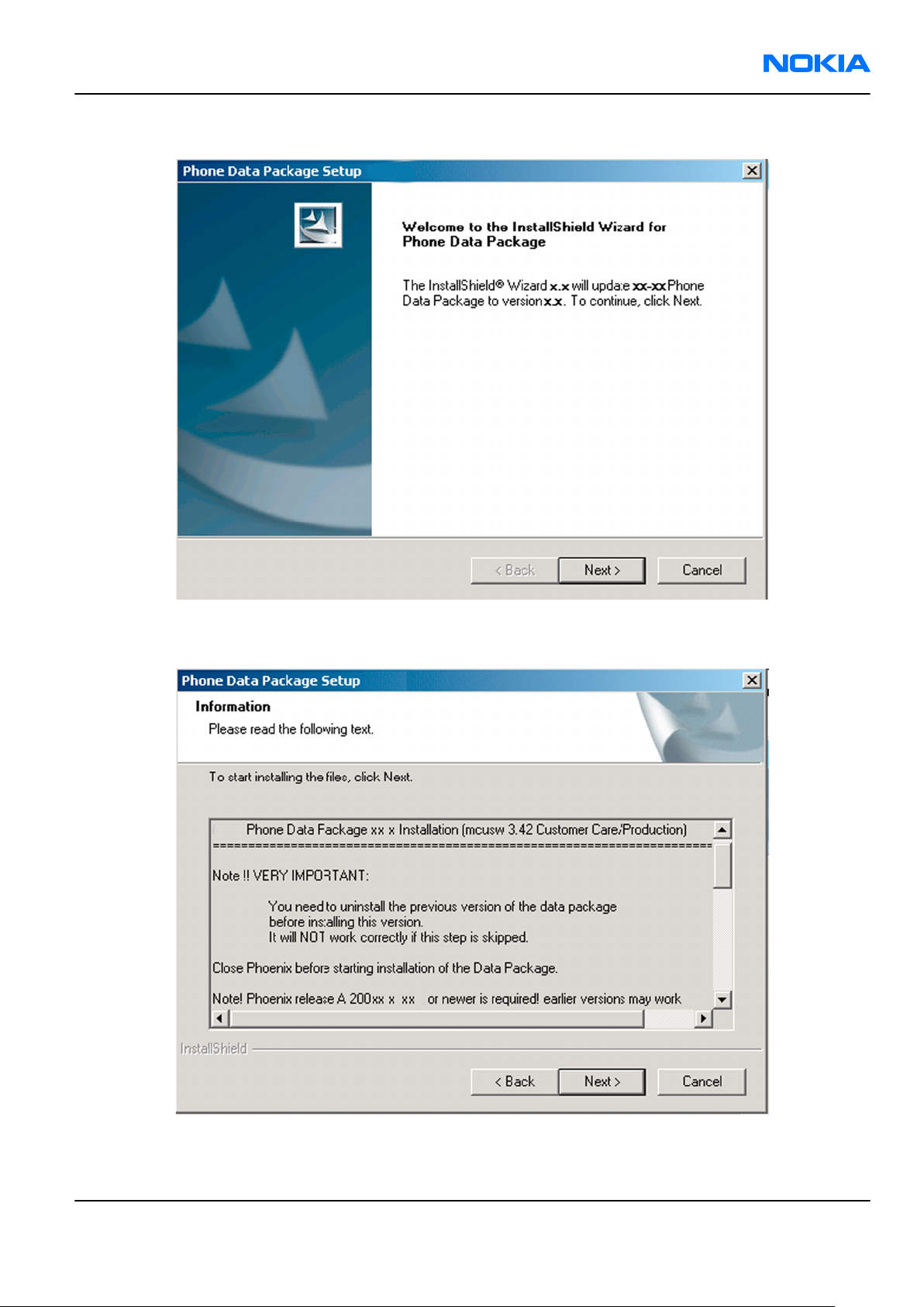
RM-178; RM-106; RM-199
Service Software Instructions Nokia Customer Care
2. Click Next.
3. In the following view you can see the contents of the data package. Read the text carefully. There is
information about the
Phoenix
version required with this data package.
Figure 12 Data package setup information
4. To continue, click Next.
Issue 1 COMPANY CONFIDENTIAL Page 3 –13
Copyright © 2006 Nokia. All rights reserved.
Page 78

RM-178; RM-106; RM-199
Nokia Customer Care Service Software Instructions
5. Choose the destination folder, and click Next to continue.
Figure 13 Data package destination folder
The InstallShield Wizard checks where
6. To start copying the files, click Next.
Phoenix
is installed, and the directory is shown.
Page 3 –14 COMPANY CONFIDENTIAL Issue 1
Copyright © 2006 Nokia. All rights reserved.
Page 79

RM-178; RM-106; RM-199
Service Software Instructions Nokia Customer Care
Phone model specific files are installed. Please wait.
7. To complete the installation, click Finish.
Figure 14 InstallShield Wizard Complete
Next actions
Phoenix
• Configuring users
• Managing connections
FPS-10 can be used after updating their flash update package files.
can be used for flashing phones and printing type labels after:
Uninstalling phone data package
Context
There is no need to uninstall an older version of a data package, unless instructions to do so are given in
the
readme.txt
Please read all related documents carefully.
file of the data package and bulletins related to the release.
Steps
1. Locate the data package installation file (e.g.
2. To start the uninstallation procedure, double-click the data package installation file.
XX-XX_dp_EA_v_1_0.exe
) from your computer.
Issue 1 COMPANY CONFIDENTIAL Page 3 –15
Copyright © 2006 Nokia. All rights reserved.
Page 80

RM-178; RM-106; RM-199
Nokia Customer Care Service Software Instructions
3. To uninstall the data package, click OK or to interrupt the uninstallation, click Cancel.
Figure 15 Uninstalling phone data package
4. When the data package is uninstalled, click Finish.
Figure 16 Finishing data package uninstallation
Alternative steps
• You can also uninstall the data package manually from
Control Panel→Add/Remove Programs→xx-xx* Phone Data Package . (*= type designator of the
phone).
Page 3 –16 COMPANY CONFIDENTIAL Issue 1
Copyright © 2006 Nokia. All rights reserved.
Page 81

RM-178; RM-106; RM-199
Service Software Instructions Nokia Customer Care
Configuring users in
Phoenix
Steps
1. Start
2. To add a new user, or to edit existing ones, click Maintain.
3. To add a new user, click New.
4. Type in the name and initials of the user, and click OK.
5. Select the desired user from the
Phoenix
If the user ID is already configured, select s/he from the
The user is added to the user name list.
service software, and log in.
Figure 17 Phoenix login
User name
drop-down list, and click OK.
User name
drop-down list, and click OK.
Figure 18 New user configured
Managing connections in
Phoenix
Context
With the Manage Connections feature you can edit and delete existing connections or create new ones.
Note: After choosing the desired connection, and connecting the phone to a PC for the first time,
allow the PC to install the USB device drivers first. Please note that this may take some time to
complete.
If there are problems after the driver installation, check that the USB connection is active from
the Windows Control Panel. If the problem persists, contact the local PC support.
Steps
1. Start
2. Choose File→Manage Connections... .
Issue 1 COMPANY CONFIDENTIAL Page 3 –17
Phoenix
, and log in.
Copyright © 2006 Nokia. All rights reserved.
Page 82

RM-178; RM-106; RM-199
Nokia Customer Care Service Software Instructions
3. To add a new connection, click Add.
4. Select Manual mode, and click Next to continue.
If you want to create the connection using the Connection Wizard, connect the tools and a phone to your
PC. The wizard will automatically try to configure the correct connection.
Figure 19 Select mode: Manual
i For an FPS-10 flash prommer with a USB Connection, choose the following connection settings:
• Media: FPS-10 USB
• DEVICE_INDEX: 0
• SERIAL_NUM: See Serial No from the label attached to the bottom of FPS-10
• ACTIVE_MEDIA: USB
ii For an FPS-10 flash prommer with a LAN connection, choose the following connection settings:
• Media: FPS-10 TCP/IP
• NET_SERV_NAME: Click Scan.... Choose your own FPS-10 device based on the correct MAC address.
See Serial No from the label attached to the bottom of your FPS-10.
• PORT_NUM: Use the default value, and click Next.
• PROTOCOL_FAMILY: Use the default value, and click Next.
• SOCKET TYPE: Use the default value, and click Next.
• TX_BUFFER_SIZE: Use the default value, and click Next.
• RX_BUFFER_SIZE: Use the default value, and click Next.
iii For an FPS-8 flash prommer, choose the following connection settings:
• Media: FPS-8
• PORT_NUM: COM Port where FPS-8 is connected
• COMBOX_DEF_MEDIA: FBUS
Page 3 –18 COMPANY CONFIDENTIAL Issue 1
Copyright © 2006 Nokia. All rights reserved.
Page 83

RM-178; RM-106; RM-199
Service Software Instructions Nokia Customer Care
iv For a plain USB connection, choose the following connection settings:
Note: First connect the DKU-2 USB cable between the PC USB port and phone.
• Media: USB
5. To complete the configuration, click Finish.
6. Click the connection you want to activate. Use the up/down arrows located on the right hand side to move
it on top of the list, then click Apply.
Figure 20 Connections list
The connection is activated, and it can be used after closing the
The connection information is shown at the right hand bottom corner of the screen.
Figure 21 Connection information
7. To use the connection, connect the phone to your PC with correct service tools. Make sure the phone is
switched on, and then choose File→Scan Product .
Manage Connection
window.
Results
The product support module information appears in the status bar:
Figure 22 Product support module information (example from RM-1)
Installing flash support files for FPS-10
Prerequisites
Note: You need to install flash support files for FPS-10 only, if you don’t have the latest Phoenix
available or the flash support files have changed after the latest Phoenix release.
• Flash support files are installed automatically, when you install Phoenix. Use Phoenix packages later than
June 2005.
• Normally it is enough to install Phoenix and the phone-specific data package because the Phoenix
installation always includes the latest flash update package files for FPS-10.
• A separate installation package for flash support files is available, and the files can be updated according
to this instruction, if updates appear between new Phoenix / data package releases
Context
If you are not using a separate installation package, you can skip this section and continue with "Updating
FPS-10 flash prommer software" (page 3–22) after installing a new phone data package.
Issue 1 COMPANY CONFIDENTIAL Page 3 –19
Copyright © 2006 Nokia. All rights reserved.
Page 84
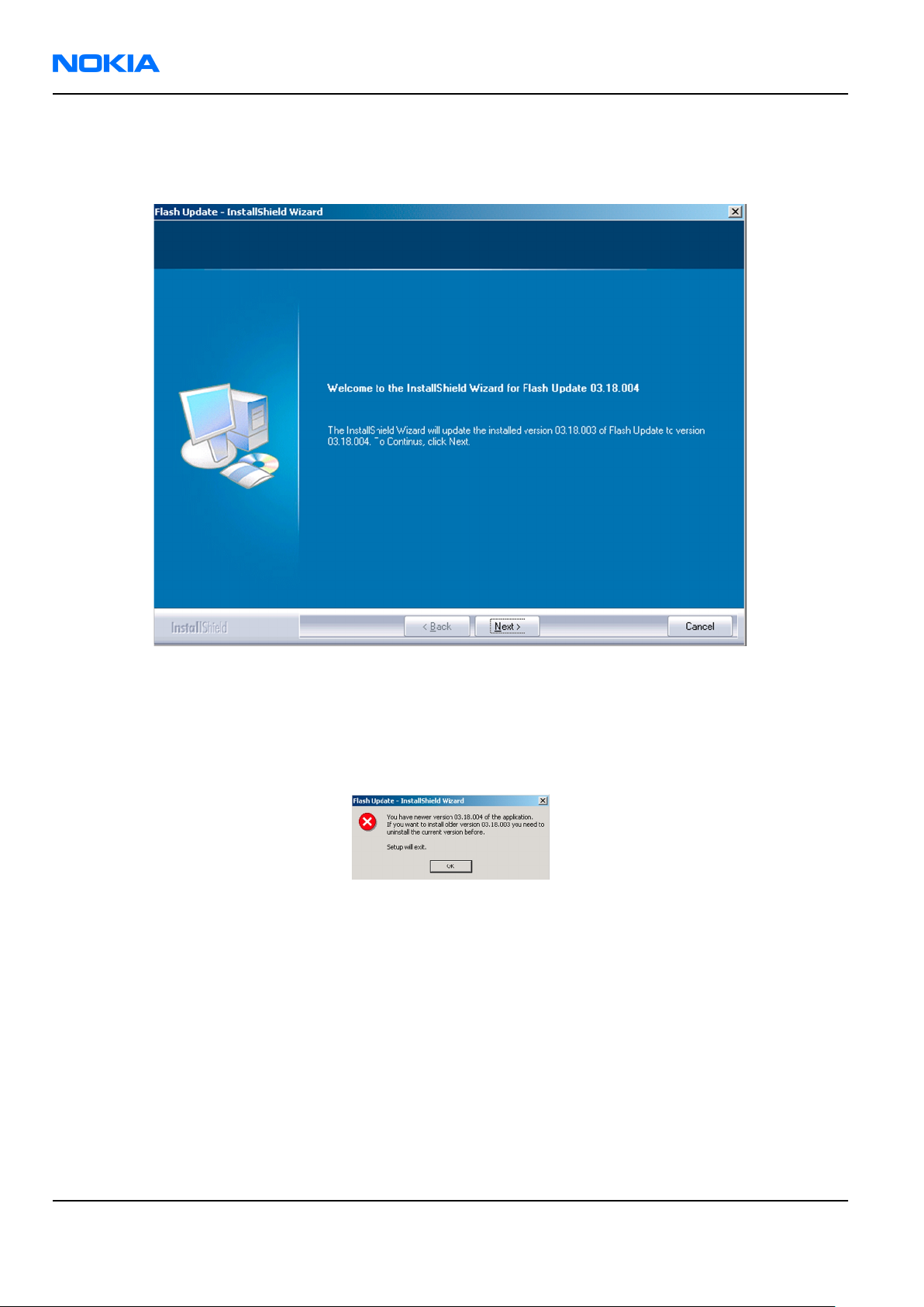
RM-178; RM-106; RM-199
Nokia Customer Care Service Software Instructions
Steps
1. To begin installation, double- click
flash_update_x_yy.exe
.
Figure 23 Flash update welcome dialog
If the same version of Flash Update package already exists, and you want to reinstall it, the previous
package is first uninstalled. Restart installation again after that.
2. If you try to downgrade the existing version to older ones, the setup will be aborted. If you really want
to downgrade, uninstall newer files manually from Control Panel and then rerun the installation again.
Figure 24 Flash installation interrupted
If an older version exists on your PC and it needs to be updated, click Next to continue installation.
Page 3 –20 COMPANY CONFIDENTIAL Issue 1
Copyright © 2006 Nokia. All rights reserved.
Page 85

RM-178; RM-106; RM-199
Service Software Instructions Nokia Customer Care
3. It is highly recommended to install the files to the default destination folder
\Phoenix
. Click Next to continue.
C:\Program Files\Nokia
Figure 25 Flash destination folder
When installing the flash update files for the first time you may choose another location by selecting
Browse. However, this is not recommended.
Issue 1 COMPANY CONFIDENTIAL Page 3 –21
Copyright © 2006 Nokia. All rights reserved.
Page 86
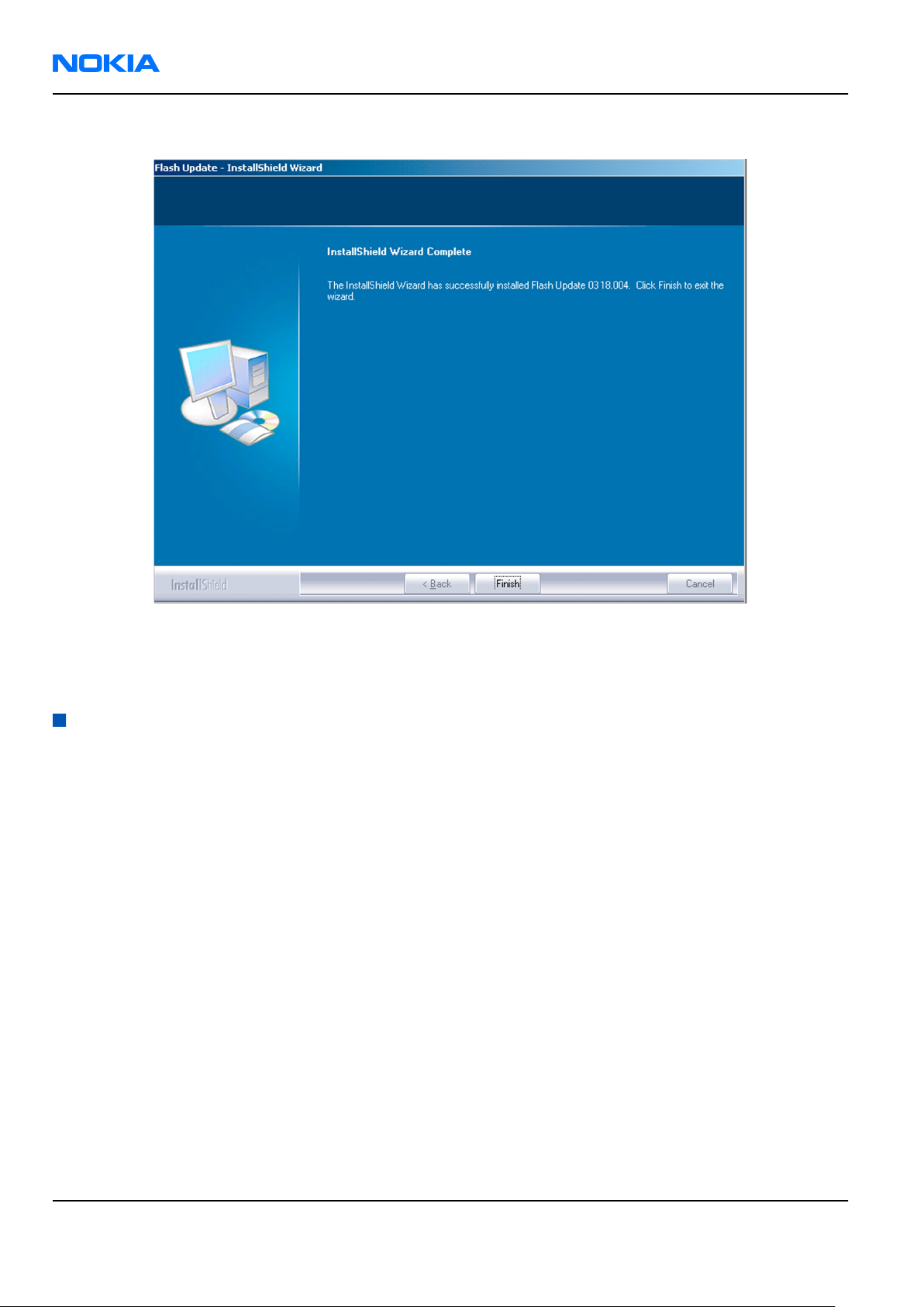
RM-178; RM-106; RM-199
Nokia Customer Care Service Software Instructions
4. To complete the installation procedure, click Finish .
Figure 26 Finish flash update
Next actions
FPS-10 flash prommers must be updated using Phoenix!
Updating FPS-10 flash prommer software
Steps
1. Start
2. Choose Flashing→Prommer maintenance .
3. When the new flash update package is installed to the computer you will be asked to update the files to
4. Alternatively you can update the FPS-10 flash prommer software by clicking the Update button.
Phoenix Service Software
your Prommer. To update the files, click Yes. Click OK if the computer informs you about an unsafe removal
of the device.
and log in, manage connection correctly for your flash prommer.
Page 3 –22 COMPANY CONFIDENTIAL Issue 1
Copyright © 2006 Nokia. All rights reserved.
Page 87

RM-178; RM-106; RM-199
Service Software Instructions Nokia Customer Care
5. Wait until you are notified that update has been successful; the procedure will take a couple of minutes.
Click OK to close the
Update Done
window.
Figure 27 Prommer SW update finished
6. If you are using the FPS-10 flash prommer, check that it is detected from the progress info. Check also the
status leds in the FPS-10. The MODE2 led (green), VBAT and POWER leds (red) should be lit. If you are using
LAN connection, the LAN led (yellow) should be blinking.
7. Check that your FPS-10 flash prommer has enough memory. Flashing the SU-18 with FPS-10 needs at least
128 MB of SRAM memory in the prommer.
Figure 28 Prommer maintenance window
Issue 1 COMPANY CONFIDENTIAL Page 3 –23
Copyright © 2006 Nokia. All rights reserved.
Page 88

RM-178; RM-106; RM-199
Nokia Customer Care Service Software Instructions
Alternative steps
• You can update FPS-10 SW by clicking the Update button and selecting the appropriate fpsxupd.ini file
in
C:\Program Files\Nokia\Phoenix\Flash
• All files can be loaded separately to the prommer used. To do this, click the right mouse button in the
Flash box files
window and select the file type to be loaded.
.
Figure 29 Flash directory window
More information can be found in Phoenix Help.
Page 3 –24 COMPANY CONFIDENTIAL Issue 1
Copyright © 2006 Nokia. All rights reserved.
Page 89

Nokia Customer Care
4 — Service Tools and Service
Concepts
Issue 1 COMPANY CONFIDENTIAL Page 4 –1
Copyright © 2006 Nokia. All rights reserved.
Page 90

RM-178; RM-106; RM-199
Nokia Customer Care Service Tools and Service Concepts
(This page left intentionally blank.)
Page 4 –2 COMPANY CONFIDENTIAL Issue 1
Copyright © 2006 Nokia. All rights reserved.
Page 91

RM-178; RM-106; RM-199
Service Tools and Service Concepts Nokia Customer Care
Table of Contents
Service tools............................................................................................................................................................4–5
AC-33...................................................................................................................................................................4–5
CA-28DS...............................................................................................................................................................4–5
CA-31D................................................................................................................................................................4–5
CA-35S.................................................................................................................................................................4–5
CA-41PS...............................................................................................................................................................4–6
CA-53...................................................................................................................................................................4–6
CA-58RS...............................................................................................................................................................4–6
CA-5S...................................................................................................................................................................4–7
CU-4.....................................................................................................................................................................4–8
DAU-9S................................................................................................................................................................4–9
DKU-2..................................................................................................................................................................4–9
FLC-2....................................................................................................................................................................4–9
FLS-4S...............................................................................................................................................................4–10
FPS-10...............................................................................................................................................................4–10
FS-10.................................................................................................................................................................4–10
JBT-9.................................................................................................................................................................4–11
MJ-77.................................................................................................................................................................4–11
PCS-1.................................................................................................................................................................4–11
PKD-1................................................................................................................................................................4–12
RJ-76.................................................................................................................................................................4–12
RJ-84.................................................................................................................................................................4–12
RJ-93.................................................................................................................................................................4–12
SA-87.................................................................................................................................................................4–13
SA-94.................................................................................................................................................................4–14
SPS-1.................................................................................................................................................................4–14
SRT-6.................................................................................................................................................................4–14
SS-34.................................................................................................................................................................4–14
SS-45.................................................................................................................................................................4–15
SS-46.................................................................................................................................................................4–15
SS-62.................................................................................................................................................................4–15
SS-84.................................................................................................................................................................4–15
ST-40.................................................................................................................................................................4–15
SX-4...................................................................................................................................................................4–16
XCS-4.................................................................................................................................................................4–16
XRF-1.................................................................................................................................................................4–16
Service concepts...................................................................................................................................................4–17
Flash concept with FPS-10..............................................................................................................................4–17
Flash concept with FPS-10 (USB)....................................................................................................................4–18
MJ-77 module jig concept...............................................................................................................................4–19
POS (Point of Sale) flash concept...................................................................................................................4–20
Service concept for RF testing and RF/BB tuning.........................................................................................4–21
CU-4 flash concept with FPS-10......................................................................................................................4–22
RF testing concept with RF coupler...............................................................................................................4–23
List of Tables
Table 8 Attenuation values....................................................................................................................................4–6
Issue 1 COMPANY CONFIDENTIAL Page 4 –3
Copyright © 2006 Nokia. All rights reserved.
Page 92

RM-178; RM-106; RM-199
Nokia Customer Care Service Tools and Service Concepts
List of Figures
Figure 30 Basic flash concept with FPS-10.........................................................................................................4–17
Figure 31 Flash concept with FPS-10..................................................................................................................4–18
Figure 32 MJ-77 module jig service concept......................................................................................................4–19
Figure 33 POS flash concept................................................................................................................................4–20
Figure 34 Service concept for RF testing and RF/BB tuning.............................................................................4–21
Figure 35 CU-4 flash concept with FPS-10..........................................................................................................4–22
Figure 36 RF testing concept with RF coupler...................................................................................................4–23
Page 4 –4 COMPANY CONFIDENTIAL Issue 1
Copyright © 2006 Nokia. All rights reserved.
Page 93

RM-178; RM-106; RM-199
Service Tools and Service Concepts Nokia Customer Care
Service tools
The table below gives a short overview of service tools that can be used for testing, error analysis and repair
of product RM-178; RM-106; RM-199, refer to various concepts.
AC-33 Power supply Universal power supply for FPS-10; included in the FPS-10 sales
package.
CA-28DS Service data cable The CA-28DS service cable is used to connect FLS-4S to the POS flash
adapter for supplying a controlled operating voltage and data
connection.
Note: Old XCS-1 cable can be used as well.
CA-31D USB cable The CA-31D USB cable is used to connect FPS-10 or FPS-11 to a PC. It is
included in the FPS-10 and FPS-11 sales packages.
CA-35S Power cable CA-35S is a power cable for connecting, for example, the FPS-10 flash
prommer to the Point-Of-Sales (POS) flash adapter.
Issue 1 COMPANY CONFIDENTIAL Page 4 –5
Copyright © 2006 Nokia. All rights reserved.
Page 94
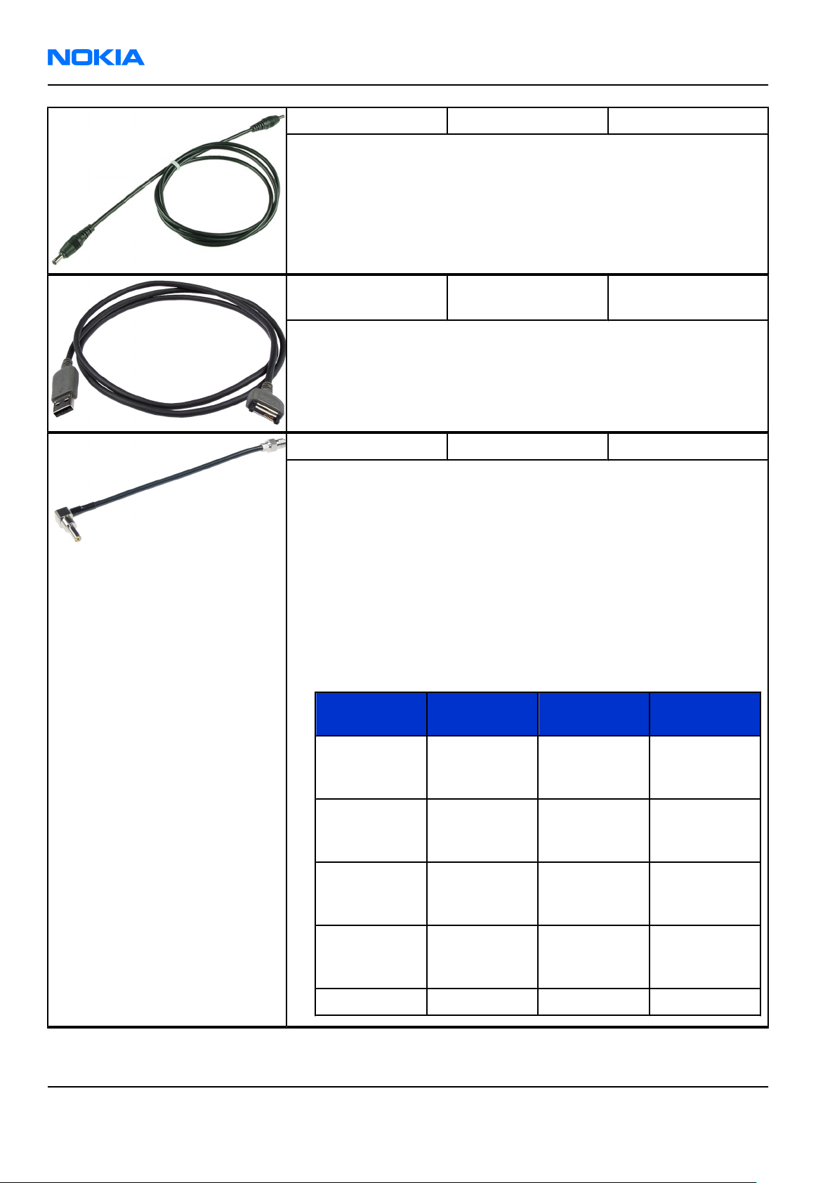
RM-178; RM-106; RM-199
Nokia Customer Care Service Tools and Service Concepts
CA-41PS Power cable Power cable for connection of e.g. the JBV-1 docking station to the
FPS-10 prommer box.
CA-53 USB connectivity
cable
USB to system connector cable.
CA-58RS RF tuning cable RF tuning cable for use with a flash adapter.
CA-58RS RF cable extends adapter features to allow RF function tests
and RF tuning in GSM bands.
Features include:
• easy to use together with flash adapter or even stand alone
• most accurate RF connection to phone module under test
• most accurate RF connection to phone module under test
• low attenuation and small “ripple” over the width of each GSM band
Note: The RF cable must be used for RF tuning.
•
Band Tuning
GSM900 Rx: 942.4
Table 8 Attenuation values
AttenuationRxAttenuation
channel
0.25 dB 0.25 dB
Tx
MHz,Tx: 897.4
MHz
GSM1800 Rx: 1842.8
0.37 dB 0.35 dB
MHz,Tx:
1747.8 MHz
GSM1900 Rx: 1950
0.4 dB 0.38 dB
MHz,Tx: 1880
MHz
WCDMA2100 Rx: 2140
0.4 dB 0.4 dB
MHz,Tx: 1960
MHz
WLAN 2442 MHz 0.42 dB 0.42 dB
Page 4 –6 COMPANY CONFIDENTIAL Issue 1
Copyright © 2006 Nokia. All rights reserved.
Page 95

RM-178; RM-106; RM-199
Service Tools and Service Concepts Nokia Customer Care
CA-5S DC cable The DC cable CA-5S is used to connect JBV-1 to the phone charger jack
for ADC/VCHAR/ICHAR calibration
Note: Old SCB-3 can be used as well.
Issue 1 COMPANY CONFIDENTIAL Page 4 –7
Copyright © 2006 Nokia. All rights reserved.
Page 96

RM-178; RM-106; RM-199
Nokia Customer Care Service Tools and Service Concepts
CU-4 Control unit CU-4 is a general service tool used with a module jig and/or a flash
adapter. It requires an external 12 V power supply.
The unit has the following features:
• software controlled via USB
• EM calibration function
• Forwards FBUS/Flashbus traffic to/from terminal
• Forwards USB traffic to/from terminal
• software controlled BSI values
• regulated VBATT voltage
• 2 x USB2.0 connector (Hub)
• FBUS and USB connections supported
When using CU-4, note the special order of connecting cables and
other service equipment:
Instructions
1 Connect a service tool (jig, flash adapter) to CU-4.
2 Connect CU-4 to your PC with a USB cable.
3 Connect supply voltage (12 V)
4 Connect an FBUS cable (if necessary).
5 Start Phoenix service software.
Note: Phoenix enables CU-4 regulators via USB when it is
started.
Reconnecting the power supply requires a Phoenix restart.
Page 4 –8 COMPANY CONFIDENTIAL Issue 1
Copyright © 2006 Nokia. All rights reserved.
Page 97

RM-178; RM-106; RM-199
Service Tools and Service Concepts Nokia Customer Care
DAU-9S MBUS cable The MBUS cable DAU-9S has a modular connector and is used, for
example, between the PC's serial port and module jigs, flash adapters
or docking station adapters.
Note: Docking station adapters valid for DCT4 products.
DKU-2 USB connectivity
cable
USB to system connector cable.
FLC-2 DC cable FLC-2 is used with a flash adapter to supply a controlled operating
voltage.
Issue 1 COMPANY CONFIDENTIAL Page 4 –9
Copyright © 2006 Nokia. All rights reserved.
Page 98

RM-178; RM-106; RM-199
Nokia Customer Care Service Tools and Service Concepts
FLS-4S Flash device FLS-4S is a dongle and flash device incorporated into one package,
developed specifically for POS use.
FPS-10 Flash prommer FPS-10 interfaces with:
• PC
• Control unit
• Flash adapter
• Smart card
FPS-10 flash prommer features:
• Flash functionality for BB5 and DCT-4 terminals
• Smart Card reader for SX-2 or SX-4
• USB traffic forwarding
• USB to FBUS/Flashbus conversion
• LAN to FBUS/Flashbus and USB conversion
• Vusb output switchable by PC command
FPS-10 sales package includes:
• FPS-10 prommer
• Power Supply with 5 country specific cords
• USB cable
FS-10 product specific
adapter
Flash adapter FS-10 is used for phone testing and flashing. FS-10 is
used with the generic flash adapter base and control Unit CU-4 or
interface adapter.
When flashing or system testing the phone, the adapter is attached to
replace the phone own battery. All functions (as well as the calibration
voltages, current and the protections for over voltages, over current
and voltage polarity), are performed by CU-4.
Page 4 –10 COMPANY CONFIDENTIAL Issue 1
Copyright © 2006 Nokia. All rights reserved.
Page 99

RM-178; RM-106; RM-199
Service Tools and Service Concepts Nokia Customer Care
JBT-9 Bluetooth test and
interface box (sales
package)
The JBT-9 test box is a generic service device used to perform
Bluetooth bit error rate (BER) testing, and establishing cordless FBUS
connection via Bluetooth. An ACP-8x charger is needed for BER testing
and an AXS-4 cable in case of cordless interface usage testing .
Sales package includes:
• JBT-9 test box
• Installation and warranty information
MJ-77 Module jig
MJ-77 is meant for component level troubleshooting.
The jig includes an RF interface for GSM and Bluetooth. In addition, it
has the following features:
• Provides mechanical interface with Engine module
• Provides galvanic connection to all needed test pads in module
• Multiplexing between USB and FBUS media, controlled by Vusb
• UI test interface
• Duplicated SIM connector
• Audio components: IHF, MIC, earpiece
• Connector for control unit
•
Access for Pop-PortTM system connector
Note: In the picture CU-4 is connected to MJ-77 . CU-4 is not
part of the MJ-77 sales package and has to be ordered
separately.
PCS-1 Power cable The PCS-1 power cable (DC) is used with a docking station, a module
jig or a control unit to supply a controlled operating voltage.
Issue 1 COMPANY CONFIDENTIAL Page 4 –11
Copyright © 2006 Nokia. All rights reserved.
Page 100
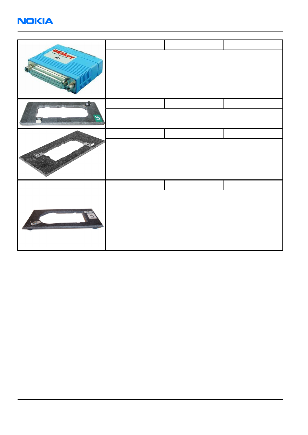
RM-178; RM-106; RM-199
Nokia Customer Care Service Tools and Service Concepts
PKD-1 SW security device SW security device is a piece of hardware enabling the use of the
service software when connected to the parallel (LPT) port of the PC.
Without the device, it is not possible to use the service software.
Printer or any such device can be connected to the PC through the
device if needed.
RJ-76 Soldering jig RJ-76 is a soldering jig used for soldering and as a rework jig for the
engine module.
RJ-84 Soldering jig
RJ-93 Rework jig RJ-93 is used as a rework jig for the engine module.
This stencil takes the front end module (FEM) or power amplifier (PA)
module for spreading the soldering paste to the component. Must be
used together with the ST-40 stencil.
Page 4 –12 COMPANY CONFIDENTIAL Issue 1
Copyright © 2006 Nokia. All rights reserved.
 Loading...