

Page 1

6090 DIN/ISO Installation Kit
Installation Guide
9359286
Issue 1
Nokia is a registered trademark of Nokia Corporation, Finnland.
© 1999 Nokia Mobile Phones. All rights reserved.
Nokia Mobile Phones operates a policy of continuous development.
Therefore, we reserve the right to make changes and improvements to
any of the products described in this guide without prior notice.
Page 2

Introduction
This installation guide has been prepared to provide the basic information required to install the 6090 DIN/ISO Installation Kit (see ISO 7736
Road Vehicles Car Radio Front Installation). The information contained in
this guide may differ from your actual work, as different types and models of vehicles will require different installation techniques. The information given is for general guidance only.
Under the terms of the warranty, this car kit must be installed by a qualified service technician and only genuine Nokia parts may be used. The
consumer should never attempt to install this car kit without professional assistance, as the installation requires special tools and skills.
Please refer to the NME-3 User‘s Guide for instructions on the telephone‘s operation, care and maintenance, including important safety information.
For your safety
1. Ensure that the vehicle‘s battery is disconnected before you start the
installation procedure and that it remains disconnected during the
procedure.
2. Do not smoke or use open flames when working near the vehicle‘s fuel
system.
3. Ensure that the vehicle‘s electrical cables, hydraulic lines, fuel lines
and safety equipment are not damaged during installation.
4. Ensure that normal control and operation of the vehicle is not impaired by the installation, particularly the brakes and steering.
5. Electronic and other sophisticated systems (e.g. speed control, ABS
anti-lock brake, fuel injection, navigation and air-bag systems) are relatively immune to malfunction caused by nearby radio transmissions.
However, should you experience false operation of these systems or
are in any doubt whatsoever as to their functionality, please consult
the vehicle‘s dealer.
6. The Installation Kit is suitable for use only in vehicles with an 11 - 12V
supply and negative grounding. Use with other supply voltages or alternative polarity will damage the equipment.
7. The phone should not be left switched on for extended periods without
running the vehicle‘s engine. Failure to comply could drain the vehicle‘s battery.
Page 3
Unpacking
Carefully unpack the equipment and make sure that the following items
are present:
1. Transceiver unit (not part of this kit)
Remove the plastic cover of the Transceiver Kit!
2. DIN/ISO console
3. DIN/ISO bracket
4. DIN/ISO slot front cover
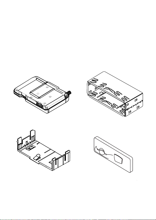
Transceiver NME-3 DIN/ISO console
DIN/ISO bracket DIN/ISO slot front cover
Page 4

Component Parts
Transceiver NME-3
The transceiver unit is supplied separately and includes all those accessories needed to complete the installation. See the installation instruc-
tions in the 6090 User‘s Guide for details of transceiver and cable
installation.
Note: The plastic cover of the transceiver must be removed before it is
installed in the DIN/ISO slot.
DIN/ISO console
The DIN/ISO console is made of steel and is to be installed in the car‘s
DIN/ISO slot.
Note: The rectangular cut-outs indicate the bottom of the console.
DIN/ISO bracket
The plastic DIN/ISO bracket slots into the DIN/ISO console and provides
a secure mounting for the transceiver unit.
DIN/ISO slot front cover
The plastic DIN/ISO slot front cover snaps into place on the front of the
DIN/ISO bracket and includes the soft plastic data cover.
Page 5

Installation
Installing the 6090 DIN/ISO Installation Kit
1. Remove the plastic cover from the transceiver unit.
2. Remove the cover from the ISO slot in the dashboard.
3. Route the connecting cables behind the dashboard (see the installa-
tion instructions in the 6090 User‘s Guide for further details).
4. Insert the DIN/ISO console into the ISO slot, and secure by bending the
locking tabs. Note that the spare slots are in the base of the frame. Ensure that the frame is firmly placed.
Note: Do not re-install the console. Always use a new part.
Page 6

5. Slide the bracket into the console until it clicks into place.
6. Attach the connecting cables to the transceiver unit through the open
slot. Slide the transceiver module into the bracket until it clicks into
place.
Page 7

7. Place the front panel onto the bracket. Push firmly until the four locking studs click into place.
8. Insert the SIM card and optional data cable.
Page 8

Removing the transceiver
The transceiver can be removed by first removing the front panel from
the bracket. The transceiver can then be released from the bracket by inserting a thin tool (e.g. credit card) between the transceiver base and the
bracket to release the locking tab (see diagrams 5 and 6).
Testing
Once installed, the equipment should be tested to ensure that it is oper-
able and that the position of the units does not impact the driver‘s ability to control and operate the vehicle in any way.
Use the transceiver to make a call when the vehicle is parked with the
engine running. During the call, switch off the engine. Ensure that the
phone is operational with the engine running and with the engine
switched off.
For operating information, refer to the User‘s Guide supplied with the
transceiver.
Operation
When initiating or receiving a call, stop the vehicle for the duration of
the call.
Warning! Do not use data equipment while the vehicle is moving.
Do not leave data equipment unsecured while driving.
 Loading...