

Page 1

PAMS Technical Documentation
NME–3 Series Transceiver
Service Software
Instructions
Issue 1
10/99
Page 2

NME–3
PAMS
Service Software Instructions
Technical Documentation
CONTENTS
Introduction 3. . . . . . . . . . . . . . . . . . . . . . . . . . . . . . . . . . . . . . . . . . . . . . . . . . . . . .
General 3. . . . . . . . . . . . . . . . . . . . . . . . . . . . . . . . . . . . . . . . . . . . . . . . . . . . . . . .
Software Environment of the Support Modules 3. . . . . . . . . . . . . . . . . . . .
Required Servicing Equipment 4. . . . . . . . . . . . . . . . . . . . . . . . . . . . . . . . . .
Installation 5. . . . . . . . . . . . . . . . . . . . . . . . . . . . . . . . . . . . . . . . . . . . . . . . . . . . . .
Mechanical Connections 5. . . . . . . . . . . . . . . . . . . . . . . . . . . . . . . . . . . . . . . . .
Installing the Software on PC Hard Disk 5. . . . . . . . . . . . . . . . . . . . . . . . . . . .
Equipment & Setup for Test / Repair 6. . . . . . . . . . . . . . . . . . . . . . . . . . . . . . .
Test Repair Setup –Block Diagram 7. . . . . . . . . . . . . . . . . . . . . . . . . . . . . .
Equipment & Flash Update Setup 8. . . . . . . . . . . . . . . . . . . . . . . . . . . . . . . . .
Flash Update Setup –Block Diagram 9. . . . . . . . . . . . . . . . . . . . . . . . . . . . .
Tuning Steps 10. . . . . . . . . . . . . . . . . . . . . . . . . . . . . . . . . . . . . . . . . . . . . . . . . . . .
1. RX Calibration (AGC + AFC) 10. . . . . . . . . . . . . . . . . . . . . . . . . . . . . . . . .
2. Alignment of Transmitter Power Levels 11. . . . . . . . . . . . . . . . . . . . . . . .
3. I/Q Modulator Alignments 13. . . . . . . . . . . . . . . . . . . . . . . . . . . . . . . . . . . .
4. A/D Calibration 15. . . . . . . . . . . . . . . . . . . . . . . . . . . . . . . . . . . . . . . . . . . . .
Common User Interface 16. . . . . . . . . . . . . . . . . . . . . . . . . . . . . . . . . . . . . . . . . . .
NME–3 Features (RU and HS) 17. . . . . . . . . . . . . . . . . . . . . . . . . . . . . . . . . . . .
Menu bar 17. . . . . . . . . . . . . . . . . . . . . . . . . . . . . . . . . . . . . . . . . . . . . . . . . . . . . .
Product 17. . . . . . . . . . . . . . . . . . . . . . . . . . . . . . . . . . . . . . . . . . . . . . . . . . . . . .
Configure 19. . . . . . . . . . . . . . . . . . . . . . . . . . . . . . . . . . . . . . . . . . . . . . . . . . . . . .
Tuning 20. . . . . . . . . . . . . . . . . . . . . . . . . . . . . . . . . . . . . . . . . . . . . . . . . . . . . . .
A/D Calibration 26. . . . . . . . . . . . . . . . . . . . . . . . . . . . . . . . . . . . . . . . . . . . . . . .
Testing 27. . . . . . . . . . . . . . . . . . . . . . . . . . . . . . . . . . . . . . . . . . . . . . . . . . . . . . .
Logic Controls 38. . . . . . . . . . . . . . . . . . . . . . . . . . . . . . . . . . . . . . . . . . . . . . . . . .
RS232 interface 40. . . . . . . . . . . . . . . . . . . . . . . . . . . . . . . . . . . . . . . . . . . . . . .
HS Test 42. . . . . . . . . . . . . . . . . . . . . . . . . . . . . . . . . . . . . . . . . . . . . . . . . . . . . .
Software 47. . . . . . . . . . . . . . . . . . . . . . . . . . . . . . . . . . . . . . . . . . . . . . . . . . . . .
Dealer 58. . . . . . . . . . . . . . . . . . . . . . . . . . . . . . . . . . . . . . . . . . . . . . . . . . . . . . .
View 68. . . . . . . . . . . . . . . . . . . . . . . . . . . . . . . . . . . . . . . . . . . . . . . . . . . . . . . . .
Help 70. . . . . . . . . . . . . . . . . . . . . . . . . . . . . . . . . . . . . . . . . . . . . . . . . . . . . . . . .
Appendix 1, Vocabulary 71. . . . . . . . . . . . . . . . . . . . . . . . . . . . . . . . . . . . . . . . . . .
Page 2
Issue 1 10/99
Page 3

PAMS
NME–3
Technical Documentation
Service Software Instructions
Introduction
General
T o run the After Sales SW , a parallel port software protection device (PKD–1) has to be
connected. The user can use WinT esla functions in modules for testing NME–3 mobile
stations (MS). The test functions send test messages from PC to MS and receive results
and show them in the PC display. The messages can be sent via M2BUS.
Note: if this software is to be run on laptops, the power saving feature MUST be switched
off.
Hardware requirements for Windows 3.1x
The recommended minimum hardware standard to run Service Software is any computer which is 386 33 MHz or greater with at least 4 MB of memory and VGA type display
(640 x 480). This assumes that only the WinTesla with After Sales Support Modules is
active, i.e. other Windows packages are not running in the background.
Hardware requirements for Windows 95
The recommended minimum hardware standard to run Service Software is any computer which has Pentium processor, memory 8 MB and meets HW requirements recommended by Microsoft.
Software Environment of the Support Modules
The Service Software user interface is intended for the following environments: Microsoft Windows 3.1x (enhanced mode) and Windows 95 environment running in enhanced mode. Support for Microsoft NT may be added, if required. Detailed information
about Windows and application usage can be found from the Microsoft Windows Version 3.1 Users Guide chapter one (Windows Basics) and chapter two (Application Basics).
As an ordinary Windows application, the main idea in the user interface is that selections
are made with menus, push buttons and shortcut keys. Selections can be done by using
keyboard and/or mouse. There is always a status bar displayed at the bottom of the
main window which contains information about current actions.
Issue 1 10/99
Page 3
Page 4

NME–3
PAMS
Service Software Instructions
Technical Documentation
Required Servicing Equipment
– Computer: At least IBM 80386 or compatible with one unused serial
port (COM1 or COM2)*), one parallel port (LPT1), hard disk recom-
mended
– Operating System: DOS Version 3.2 or later
– If PCLStart in use: DOS 6.22 and IBM 80486 or compatible
– Display: Any 80–character text display
– Service software version for 3.5” disk (product code: )
– Software protection key PKD–1 (product code: 0750018)
Detailed equipment is shown on
*)
Note: A number of PC’s of an older generation use the Intel, National Semiconductor, or United
Microelectronics IC 8250 as the serial port UART. This is a comparatively inefficient circuit for current
purposes and does not necessarily support the M2BUS adapter at 9600 baud. The newer UART’s
NS16450 and NS16550AF of National Semiconductor offer solutions for these problems.
Equipment Setup
pages
Page 4
Issue 1 10/99
Page 5

PAMS
NME–3
Technical Documentation
Service Software Instructions
Installation
Mechanical Connections
Caution: Make sure that you have switched off the PC and the printer
before making connections.
Caution: Do not connect the PKD–1 key to the serial port. You may
damage your PKD–1 !
The software controls the phone via a separate adapter connected to the serial port of
the PC, and to the telephone’s M2BUS (DAU–9S).
Attach the dongle PKD–1 to the parallel port 1 (25–pin female D–connector) of the PC.
When connecting PKD–1 to the parallel port, be sure that you insert the computer side
of the PKD–1 to the PC (male side). If you use a printer on parallel port 1, install the
PKD–1 between the PC and your printer cable.
The PKD–1 should not affect devices working with it. If some errors occur (errors in
printing are possible) please try printing without the PKD–1. If printing is OK without the
PKD–1 please contact your dealer . We will offer you a new PKD–1 in exchange for your
old one.
Installing the Software on PC Hard Disk
The program is delivered on a diskette and is copy protected with a dongle PKD–1. It
must be present in parallel port when using Service software.
The program can also be installed on the hard disk, which is recommendable to obtain
a maximum data access rate.
Keep the original diskette safe to enable upgrading of the program !
If you plan to use PCL Start service software, you must install it before installing Service
software, see PCL Start installation instructions.
To install the new Service software program, follow the steps below:
1. insert the new Service software diskette
into drive A: of your computer
2. start Windows, and open File Manager
log into drive a:
type
A:
and press <Enter>
3. start SETUP.EXE and
install Service software to drive C:
Issue 1 10/99
type C: and press <Enter>
Page 5
Page 6
NME–3
PAMS
Service Software Instructions
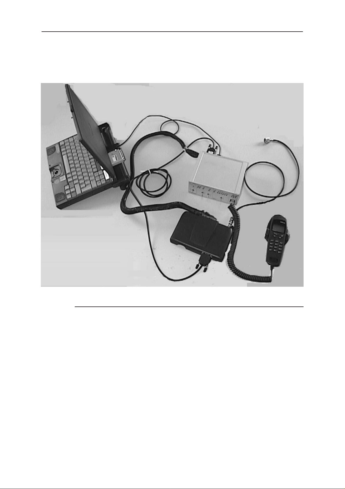
Equipment & Setup for Test / Repair
7
2
1
6
Technical Documentation
3
8
5
9
Item: Description Product code:
1
2 PKD–1 Software protection key 0750018
3 JBD–2 Test / repair box 0770171
4
5 SCD–2A Repair Place Cable 0730171
6 AXS–4 D9 – D9 Cable 0730090
7 DAU 9S MBUS Cable 0730108
8 RF Cable 4626009
9
PC
Handset
Radio Unit
–
–
–
4
Page 6
Issue 1 10/99
Page 7
PAMS
NME–3
Technical Documentation
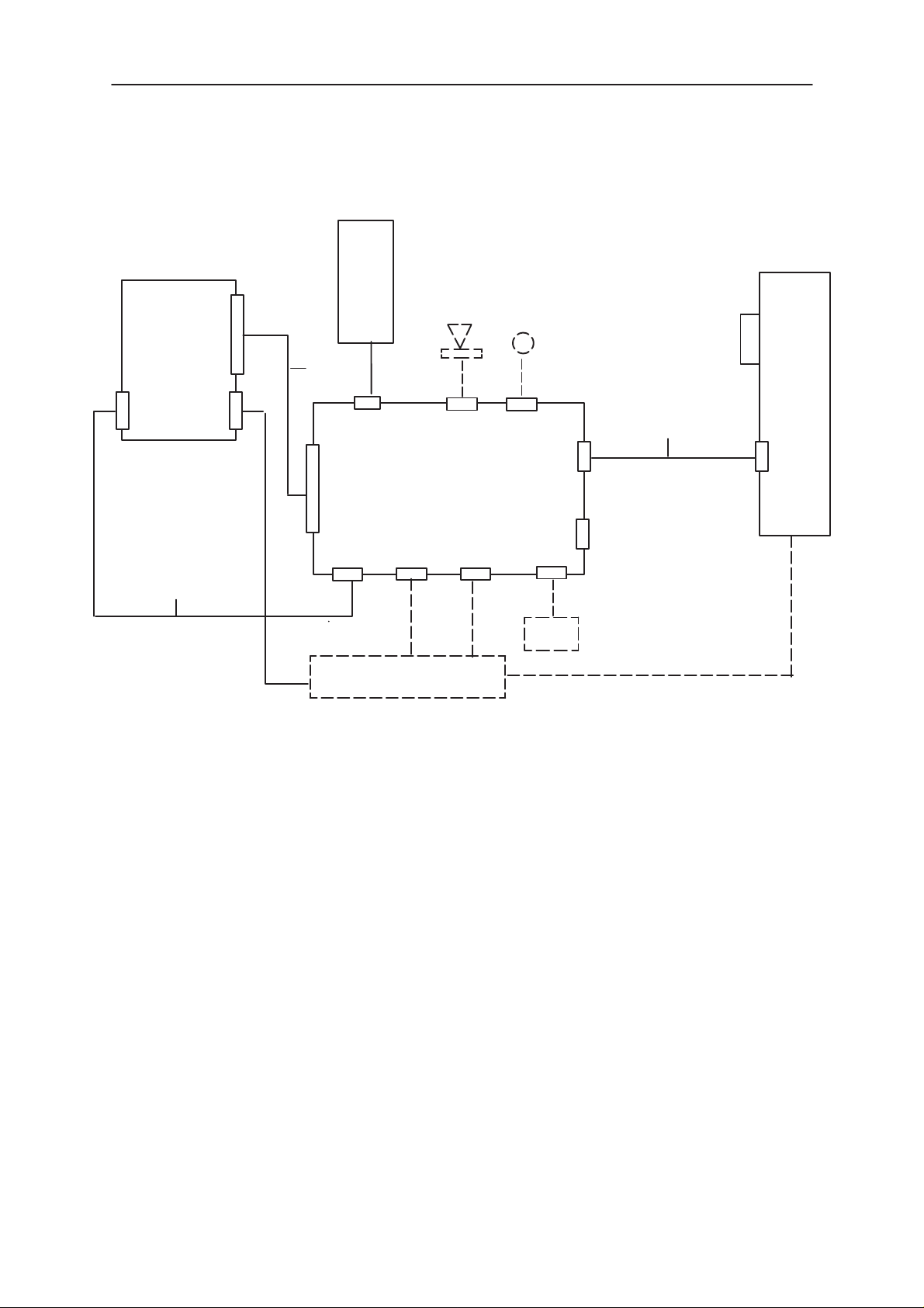
Test Repair Setup –Block Diagram
H/SET
SYSTEM
CONNECTOR
RADIO UNIT
RS232
RF
SCD–2
PHONE
CONNECTOR
HS
JBD–2
EAR MIC
Service Software Instructions
PKD–1
PC
DAU–9S
SERIAL
GPIB
AXS–4
RS232 AIN AOUT
POWER SUPPL Y
CMD
NOTE: ITEMS IN BROKEN LINES NOT SHOWN IN PHOTO
Issue 1 10/99
Page 7
Page 8
NME–3
PAMS
Service Software Instructions
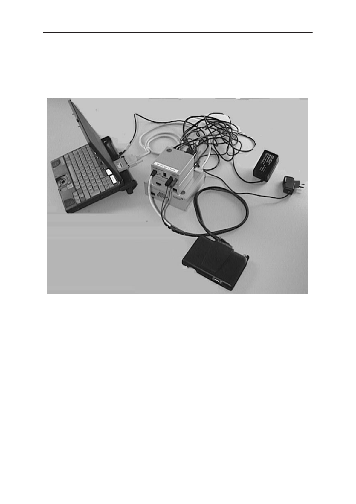
Equipment & Flash Update Setup
10
1
2
3
4
5
Technical Documentation
7
6
9
8
Item: Description: Product code:
1
2 PKD–1 Software protection key 0750018
3 FLA_7 Flash Loading Adapter 0770119
4 TDF–4 Flash Security Box 0770106
5 FPS–4S Flash Prommer 0085095
6 ACH–6 Power Supply (Euro) 0270381
7 AC Charger ACL–3E 0680015
8
9 SCD–5 Flash Update Cable 0730170
10 Printer Cable 0730029
* AXS–4 D9 – D9 Cable 0730090
* SCF–7 Power Cable (FLA–7 to FPS–4S) 0730141
* AXS–5 D15 – D15 Cable 0730091
PC
Radio Unit
–
–
Page 8
(* hidden items)
Issue 1 10/99
Page 9
PAMS
NME–3
Technical Documentation
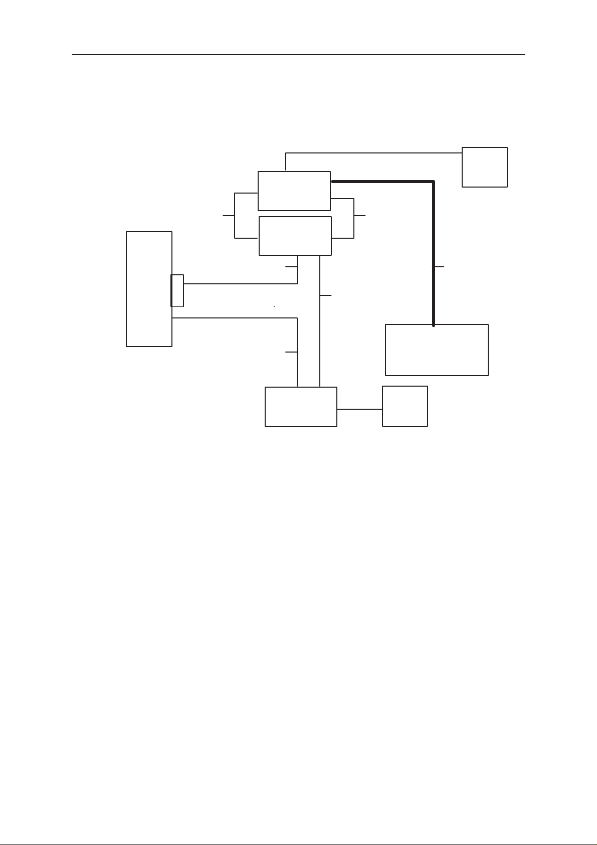
Flash Update Setup –Block Diagram
FLA–7
SCF–7
FPS–4S
PRINTER CABLE
PC
PKD–1 AXS–4
AXS–4
Service Software Instructions
ACL–3E
AXS–5
SCD–5
NME–3 RU
TDF–4
ACH–6
Issue 1 10/99
Page 9
Page 10

NME–3
PAMS
Service Software Instructions
Tuning Steps
1. RX Calibration (AGC + AFC)
Procedure
Follow the steps described in chapter ”Service Software Instructions”
section ”RX calibration... command”.
Software reports the following:
AFC init value
AFC slope
PSW slope
AGC DAC values and the corresponding voltages for each gain step (0 57 dB)
Technical Documentation
Limits for the reported values
If everything went well the reported values should approximately be the
following:
Parameter Low limit High limit
AFC init value –80 80
AFC slope 135 230
PSW slope 250 350
AGC 0 dB 440 740
AGC 57 dB 60 360
Difference between the two neighbour
AGC steps
10 20
Troubleshooting
If the calibration does not succeed the software normally reports ”Unable
to read data from phone” or ”Failed to set high reference” or ”Failed to set
low reference”.
Page 10
In this case check first the basic functionality of the receiver chain: RF
generator frequency set as in the calibration and level for example to the
high reference value.
Then go to the RSSI reading menu (under RF controls). If the reading is
very low there is something broken in the receiver and must be found by
measuring voltages and signal levels at different places (information of
these can be found elsewhere in this manual).
Issue 1 10/99
Page 11

PAMS
NME–3
Technical Documentation
If the RSSI reading seems to be within 5 - 10 dB the same as the RF input
level check that the VCTCXO (G650) frequency is close enough the
wanted frequency. This is most easiest done by measuring the UHF VCO
(G550) frequency because the absolute value of the deviation is biggest
there. In the GSM mid channel the UHF–VCO frequency should be 1018
MHz. If the deviation is bigger than about +/–20 kHz it is probable that the
VCTCXO is not operating correctly.
If both of these (RSSI reading and the frequency) seem to be correct and
calibration still fails the most probable reason is that there is a little lack of
gain somewhere or the AGC gain control slope in N600 is out of the limits.
This can be verified by changing the generator reference levels from the
demanded ones in the calibration procedure in 1 dB steps up and down. If
the calibration goes through with some reference levels the corrective
action is most probably changing N500 or N600.
Service Software Instructions
2. Alignment of Transmitter Power Levels
Equipment:
– Pulsed power meter or spectrum analyzer and 10 dB attenuator.
– MSJ–13 voltage source within 9–15VDCV.
The following settings for the spectrum analyzer are recommended when
aligning the power levels: zero span, resolution and video bandwidths 1
MHz, input attenuation 40 dB, sweep time 1 ms, video triggering.
Procedure:
Follow the instructions given in chapter ”Service Software Instructions”
section ”TX power... command”.
For GSM the alignment channel is 60 (902 MHz)
Issue 1 10/99
Page 11
Page 12
NME–3
Á
Á
Á
Á
Á
Á
PAMS
Service Software Instructions
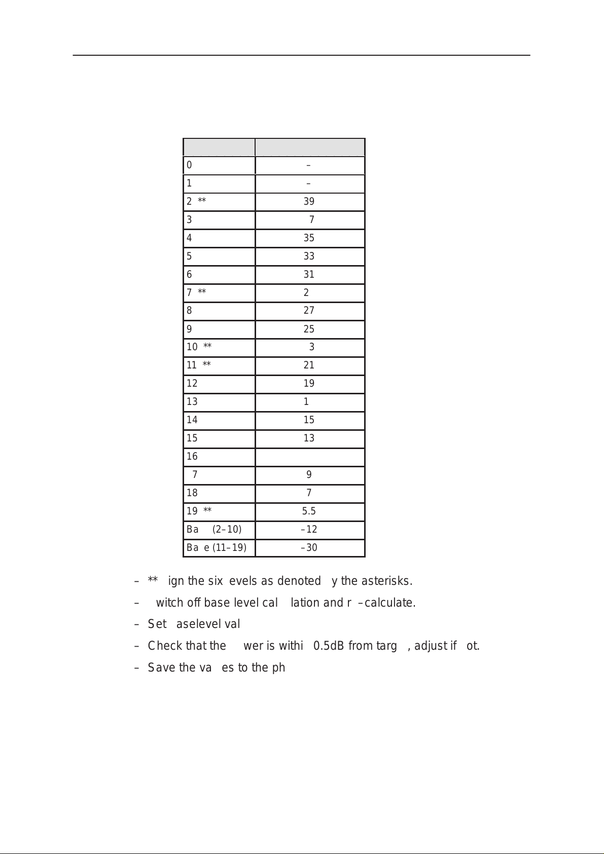
Targets in dBm:
Power level GSM
0
1
2 **
3
4
5
ÁÁÁÁ
6
7 **
8
9
10 **
–
–
39
37
35
ББББББ
33
31
29
27
25
23
Technical Documentation
11 **
ÁÁÁÁ
12
13
14
15
16 **
17
ÁÁÁÁ
18
19 **
Base (2–10)
Base (11–19)
ББББББ
ББББББ
21
19
17
15
13
11
9
7
5.5
–12
–30
– **Align the six levels as denoted by the asterisks.
– Switch off base level calculation and re–calculate.
– Set baselevel values.
– Check that the power is within 0.5dB from target, adjust if not.
Page 12
– Save the values to the phone.
Issue 1 10/99
Page 13

PAMS
NME–3
Technical Documentation
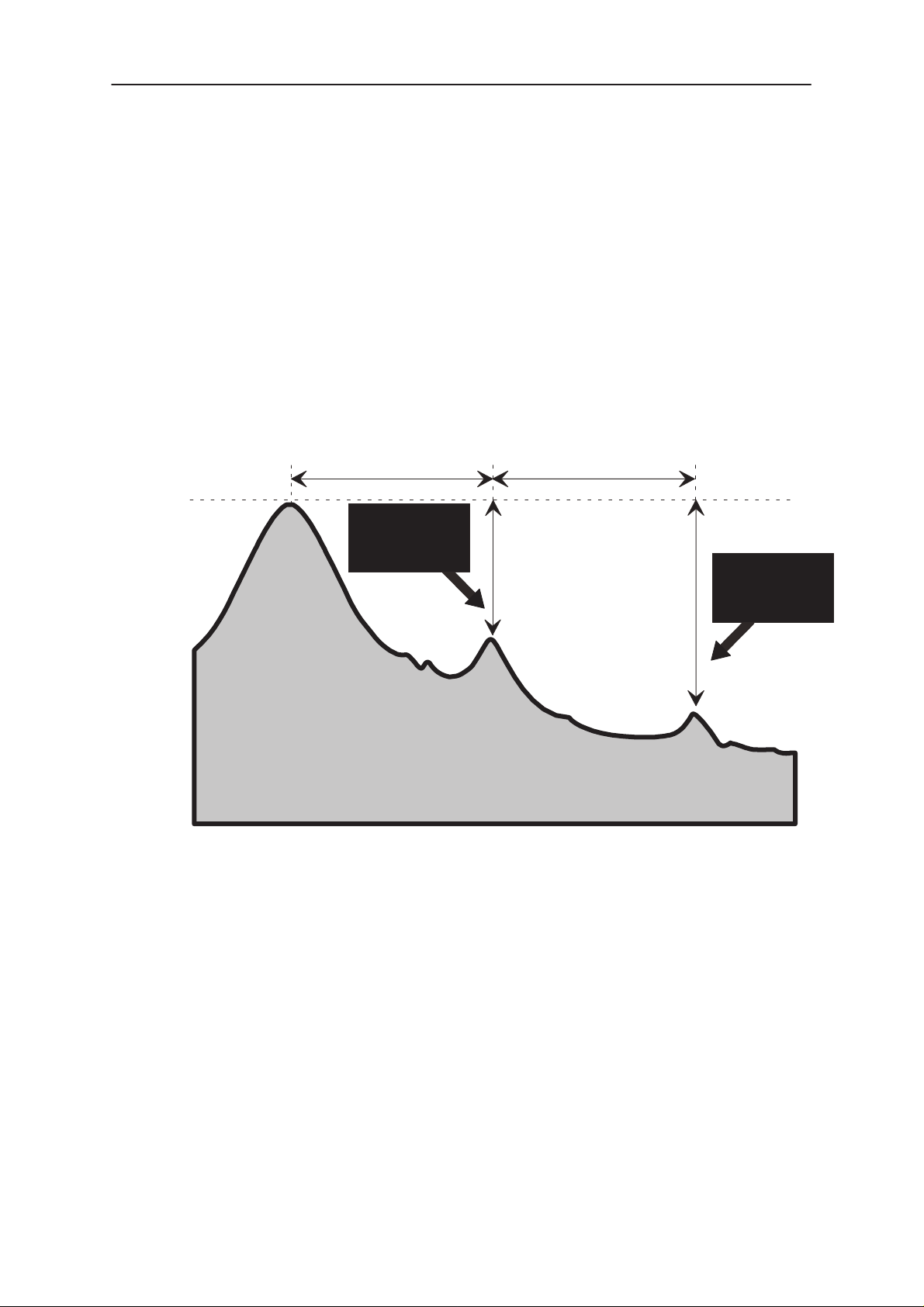
3. I/Q Modulator Alignments
Procedure:
Connect the spectrum analyzer to the phone antenna connector. The
recommended spectrum analyzer settings are: span 200 kHz, resolution
BW 10 kHz, video BW 1 kHz, sweep 500 ms, input attenuation 30 dB.
– From
– Go to
MHz).
– Select the ”TX I DC offset” option and adjust the level of the centre fre-
quency (CHF) to minimum.
– Select the ”TX Q DC offset” option and adjust the level of the CHF
again to minimum.
– After finding both minima change ”TX I DC offset” by step or two from
the current value to both directions to see, whether better minimum
can be found for CHF.
RF controls
TX I/Q tuning
menu make sure that TX data type is 1.
menu. The alignment channel for GSM is 60 (902
Service Software Instructions
– Select the ”Amplitude Difference” option and adjust the level of the un-
wanted sideband CHF + 67.71 kHz to minimum.
– Select the ”Phase Difference” option and dajust the level of CHF +
67.71 kHz again to minimum.
– After all the minima have been found press ”OK” button to store the
values to phone EEPROM.
Targets:
The level of the centre frequency CHF should be at least 30 dB down to
the wanted sideband CHF - 67.71 kHz.
The level of the unwanted sideband CHF + 67.71 kHz should be at least
35 dB down to the wanted sideband CHF - 67.71 kHz.
Issue 1 10/99
Page 13
Page 14
NME–3
PAMS
Service Software Instructions
Alignment Verification
– Go to
Product ––> Initialize ––> Normal mode
a SW reset for the phone. Which in turn is needed to get the aligned
I/Q values in use.
– Go to
RF controls
level 10, TX data type 1.
– Check the levels of CHF and CHF + 67.71 kHz. Both the levels
should be at least 30 dB down to the wanted sideband CHF - 67.71
kHz. If both or either of the specifications is not met adjust the required
values (I and Q DC offsets for CHF and amplitude and phase for CHF
+ 67.71kHz) to meet the specifications.
Technical Documentation
. This is needed to give
menu and start transmission on channel 60, power
–67.71 kHz +67.71 kHz
D.C. offset
tunings:
Set this value
to minimum
CHF
> 30 dB
> 35 dB
Amplitude &
phase difference:
Set this value
to minimum
Page 14
Issue 1 10/99
Page 15

PAMS
NME–3
Technical Documentation
4. A/D Calibration
Equipment
– Refer to repair place setup.
Procedure
– Connect phone to repair place.
– Start up WinTesla.
– Choose tuning menu and then A/D Calibration
– Press
– Check that CCont Voltage result is OK.
Run.
Service Software Instructions
Issue 1 10/99
Page 15
Page 16
NME–3
PAMS
Service Software Instructions
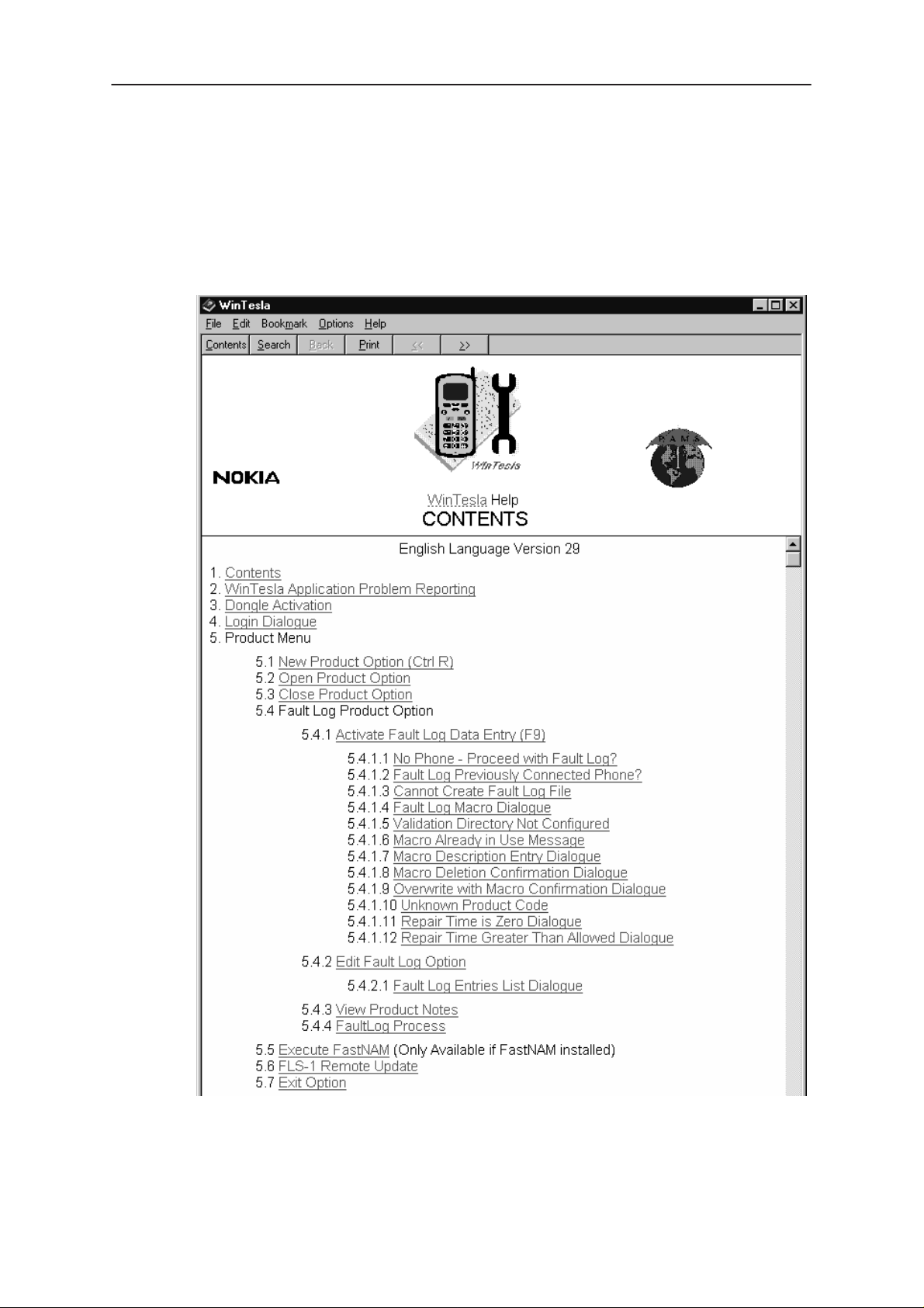
Common User Interface
All WinTesla files share a common interface which are detailed in the
WinTesla help files once the software is installed. A typical example is
shown in the figure below.
Technical Documentation
Page 16
Issue 1 10/99
Page 17
PAMS
NME–3
Technical Documentation
Service Software Instructions
NME–3 Features (RU and HS)
Menu bar
After Sales SW’s menus follow the menu structure specified in WinTesla User Interface
Specification. This specification will describe functionality that differs from WinTesla
specification.
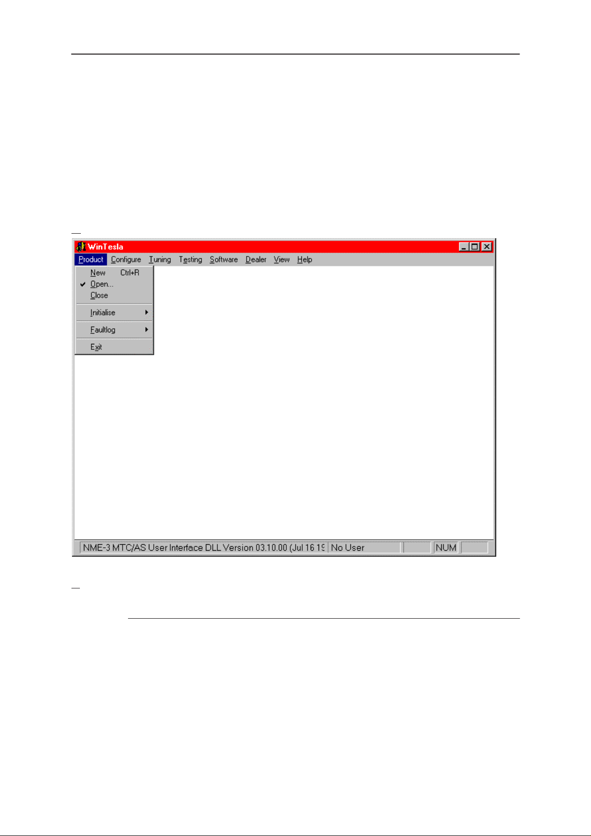
Product
New command
Activation Status Bar Text
Alt, P, N Rescan a new phone
Ctrl+R
If phone is changed (with same phone type only serial number is changed) phone will be
initialised to local mode. If phone is changed to different phone type the current DLLs
are unloaded and new ones are loaded for that phone.
If the Quick/RF Info view is open, window will be automatically updated.
If Phone Information view is open, it will be automatically updated.
NOTE: When different type of phone is changed user should select Product/New, so that
application recognises phone type change and loads correct menu.
Issue 1 10/99
Page 17
Page 18

NME–3
PAMS
Service Software Instructions
Open... command
Activation Status Bar Text
Alt, P, O Force load phone specific functionality
Phone is set to local mode.
I
nitialise... command
Activation Status Bar Text
Alt, P, I
Opens a submenu
N
ormal Mode
Activation Status Bar Text
Technical Documentation
Alt, P,I, N Initialises phone to normal mode
F5
When normal mode has been activated or program has been started, self–test results
will be asked from MCU. If any fault was found in the tests, an error message is shown. If
normal mode has been set successfully (no self test error has been found), and paging
listening has been started, the used AFC value is requested from MS.
Initialisation routine checks phone’s cellular type and if unsupported phone is detected,
application unloads the DLLs.
The After Sales SW sets automatically the MS state to normal mode when needed.
If phone identification view is open, window will be automatically updated. Also if RF In-
formation Window is open it will be updated to quick info view.
NOTE: When phone is changed to but phone type does not change, user may select
Product/Initialise/Normal Mode instead of Product/New.
Local Mode
Activation Status Bar Text
Alt, P,I, L Initialises phone to local mode
Shift+F5
Selection will change the MS state to
ing menus, the After Sales SW software will change automatically the MS state to local.
The After Sales SW sets automatically the MS state to normal mode when needed.
Also if quick info view is open it will be updated to RF Information view.
Page 18
local
. When user selects item from T esting or T un-
Issue 1 10/99
Page 19
PAMS
NME–3
Technical Documentation
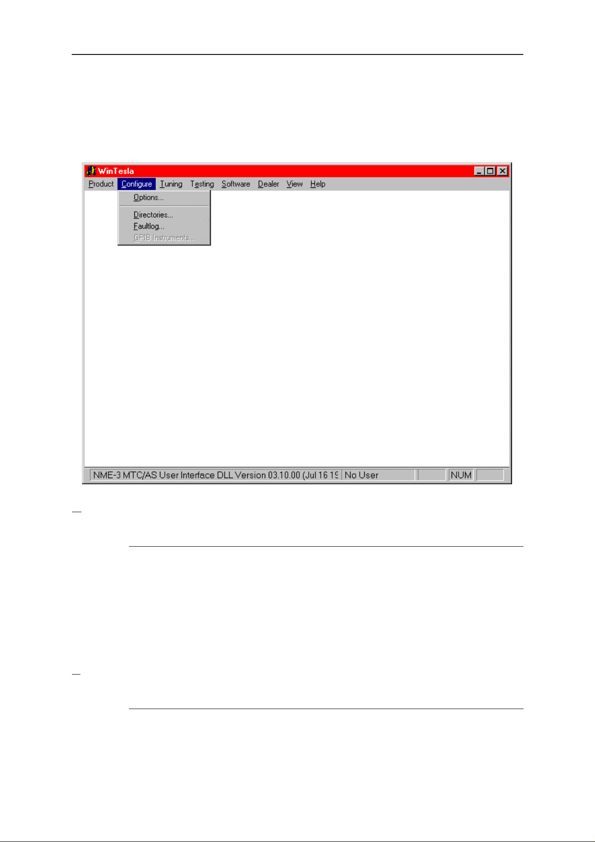
Configure
Service Software Instructions
Options
Activation Status Bar Text
Alt, C,O
Opens the ”General Configuration” menu, where language, user ID, com
port,....... can be selected.
irectories
D
Activation Status Bar Text
Alt, C,D
Opens the ”Directory Settings” menu, where the used directories can be
modified.
Issue 1 10/99
Page 19
Page 20
NME–3
PAMS
Service Software Instructions
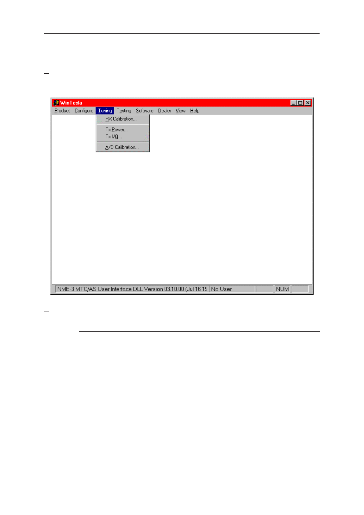
Tuning
The tuning menu offers functions for ME adjustments.
Technical Documentation
RX Calibration... command
Activation Status Bar Text
Alt, T,R Open RX Calibration dialog box
Starts RX calibration.
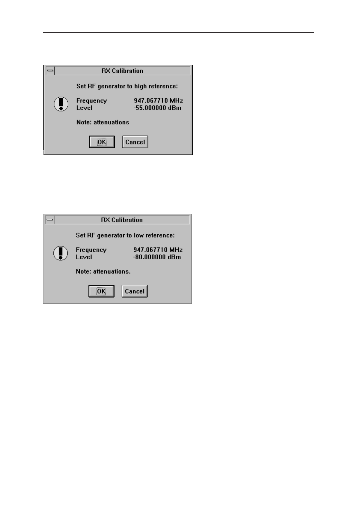
The next automatic selections are made when this tuning function is activated:
• Phone is set to local mode
• Update RF information window
The measurement is started automatically when RX calibration is entered. The measurement is done in five steps:
1. User is requested to put signal generator to high input level (read from .INI file).
Page 20
Issue 1 10/99
Page 21
PAMS
NME–3
Technical Documentation
2. Measurement with high input level is executed
3. User is requested to put signal generator to low input level (read from .INI file).
Service Software Instructions
4. Measurement with low input level is executed
Issue 1 10/99
Page 21
Page 22
NME–3
PAMS
Service Software Instructions
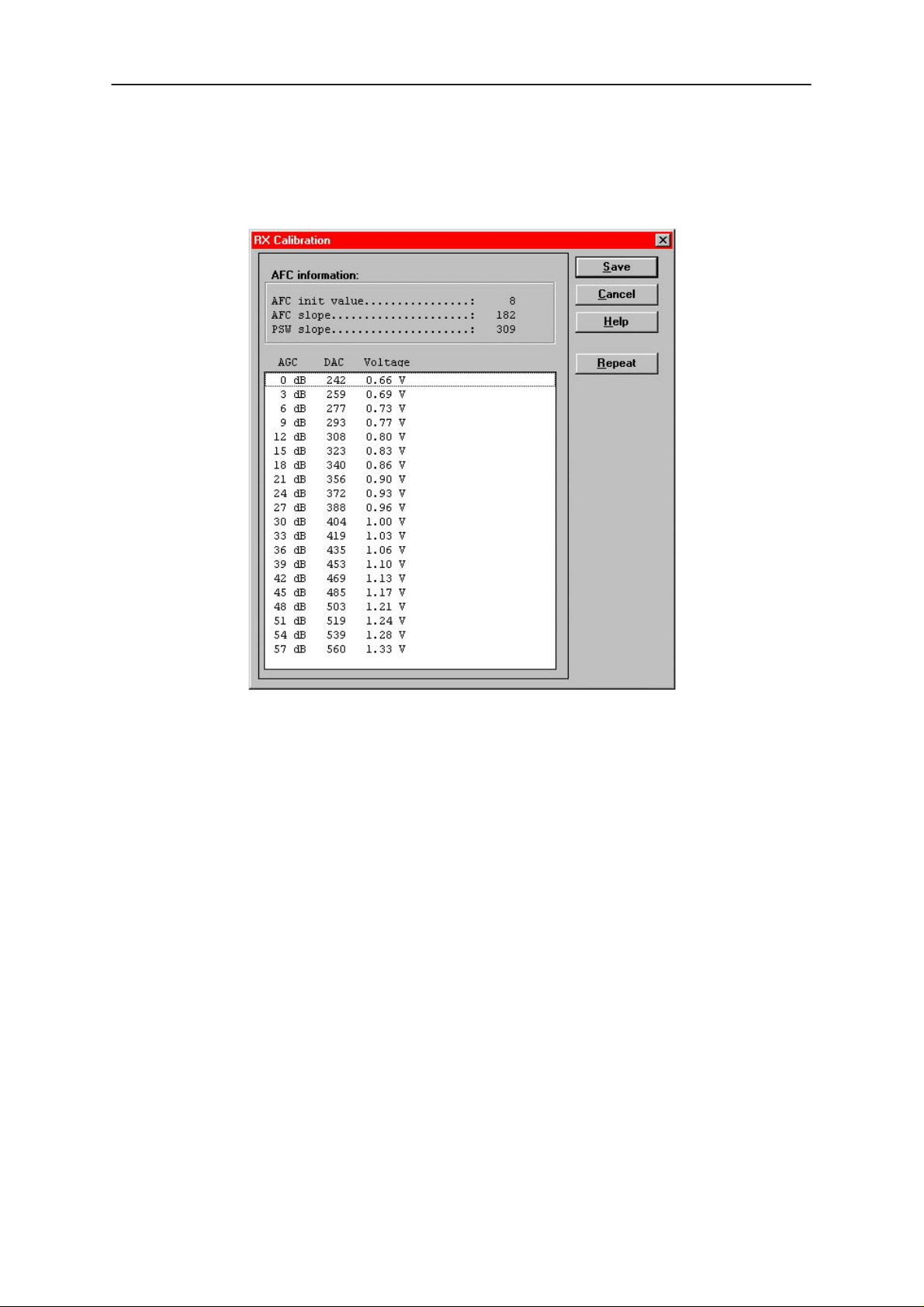
5. The RX Calibration dialog will be updated when previous steps are done.
Technical Documentation
Dialog mode: modal
RX Calibration dialog has the following items:
AFC information box:
Shows AFC init value, AFC slope and PSW slope values.
AGC List box (ALT+A):
AGC, DAC, Voltage.
Repeat button (ALT+R):
The measurement can be started again by pressing this button.
Save button (ALT+S):
Dialog is closed and tuning
Cancel button (ESC):
Dialog is closed and tuning
When calibration is ended, the DAC value checking is made and if it is not succeeded,
error message is shown.
When exit is made, the next selections are set to the values which were selected before
this adjustment.
is saved
to phone.
is not saved
to phone.
Page 22
Issue 1 10/99
Page 23

PAMS
NME–3
Technical Documentation
Tx Power... command
Activation Status Bar Text
Alt, T,P Open TX Power Tuning dialog box
Starts TX power tuning.
Service Software Instructions
Issue 1 10/99
Page 23
Page 24

NME–3
PAMS
Service Software Instructions
The TX Power Tuning dialog will be activated automatically after value selection.
Technical Documentation
Dialog mode: modal
TX Power Tuning dialog has following items:
Power Level & Coefficients list box (ALT+L):
The power is presented in GSM or values. The base power is selected automatically
when the dialog is opened. The test value is not saved to the EEPROM. The test value
can be changed during tuning as other power coefficients and the program remembers
its value when tuning function is activated later again.
If there is more power levels in the phone that can fit into window the window is scrollable. When phone is initialised the program asks the number of power levels used in the
phone.
Only six power coefficients are needed to tune (left justified Coefficients) and the rest of
them are calculated.
The tuning position is highlighted and can be tuned with +/– keys or left/right cursor
keys.
Calculate button (ALT+A):
The calculation is activated with this button. The power coefficients which are calculated
from the tuned coefficients are displayed on the different columns than the others. All
values can be tuned if needed.
Save button (ENTER):
Dialog is closed and tuned values are
Page 24
saved
to phone.
Issue 1 10/99
Page 25

PAMS
NME–3
Technical Documentation
Cancel button (ESC):
Dialog is closed and tuning
When selections are used, the power value checking is made and if it is not succeeded,
error message is shown. The test checks that all power coefficients are in descending
order (same order than power levels).
If the power tuning function is ended and EEPROM values are not received or EEPROM
fault is noticed, an error message is shown.
When all power coefficients have such values that they don’t cause any error messages, save can be made. The last used tuning power is in use after exit.
The next automatic selection is made when this tuning function is ended:
Operation Mode = RX pulsed
Tx I/Q
Activation Status Bar Text
... command
is not saved
to phone.
Service Software Instructions
Alt, T,Q Open TX I/Q Tuning dialog box
This function is used for tuning TX I and Q branch DC offset, amplitude difference and
phase difference.
The function opens same Start Tuning dialog as with TX Power Tuning.
The next automatic selections are made when this function is activated:
Operation Mode = TX pulsed
Update RF Information window
The TX I/Q Tuning dialog is opened.
Dialog mode: modal
TX I/Q Tuning has following items:
Tune TX I
The DC Offset is shown as percents (%) from the ± maximum value. 0% means that
there is no DC. The value range is –100%...100%. The value is rounded to the nearest
integer value.
Tune TX Q
Issue 1 10/99
DC Offset scroll bar (ALT+I):
DC Offset scroll bar (ALT+Q):
Page 25
Page 26

NME–3
PAMS
Service Software Instructions
The operation of this function is the same as one above, except with this selection the Q
branch DC Offset is tuned. The value range is –100%...100%. The value is rounded to
the nearest integer value.
Tune A
When this selection is made user can increase or decrease the amplitude difference
within 0.1 dB steps. The value range is –1...1.
Tune P
When this selection is made user can increase or decrease the phase difference within
0.5° steps. The current phase difference is shown on the tuning window with numbers
and bar figure. The value range is 85...95.
Save button (ENTER):
Dialog is closed and tuning
Cancel button (ESC):
Dialog is closed and tuning
After each value change the new value is sent to the phone.
mplitude Difference scroll bar (ALT+A):
hase Difference scroll bar (ALT+P):
is saved
is not saved
to phone.
to phone.
Technical Documentation
The next automatic selection is made when TX I / Q tuning function is ended:
Operation Mode = RX pulsed
Update RF Information window
A/D Calibration
The A/D converter of CCONT Voltage is calibrated. First select the A/D
converter for calibration, then edit the appropriate calibration voltage. By
pressing the RUN button the calibration procedure is started and the result
is shown in the text box.
Page 26
Issue 1 10/99
Page 27

PAMS
NME–3
Technical Documentation
Testing
The Testing sub menu offers functions for ME testing.
Audio Loops
Service Software Instructions
RF Controls... command
Activation Status Bar Text
Alt, E,F Open RF Controls dialog box
This function is used for RF testing.
Command opens RF Controls dialog, which contains data for testing and adjustments.
Issue 1 10/99
Page 27
Page 28

NME–3
PAMS
Service Software Instructions
Technical Documentation
Dialog mode: modal
RF Controls dialog has following items:
Active Unit group:
RX radio button (ALT+R):
RX
When
– AGC is controlled
– RX continuous mode channel is activated
The RX value is always given as default.
Note! Function is activated immediately, Apply is not needed.
TX radio button (ALT+T):
When
is selected, the next functions are made:
Data transmission is deactivated
TX power is deactivated
If operation mode is continuous,
RF Information window is updated
TX
is selected, the next functions are made:
Data transmission is activated
If operation mode is continuous,
– Operation mode is set to burst
RF Information window is updated
Continuous mode radio button is disabled.
Note! Function is activated immediately, Apply is not needed.
Operation Mode group:
Continuous radio button (ALT+C):
Page 28
Issue 1 10/99
Page 29

PAMS
NME–3
Technical Documentation
When
selection
Note! Function is activated immediately, Apply is not needed.
Burst radio button (ALT+B):
When
thesiser control sequence
Channel selections
power is connected
continuous
burst
selection is used,
selection is used,
synthesiser is set to constant frequency
synthesiser channel number is as given with Continuous Mode Channel
transmitter power is not connected
if Active Unit is RX, AGC is controlled
synthesiser is controlled by using receiving/transmission/measuring syn-
synthesiser channel numbers are as given with Channel/Monitoring
if Active Unit is TX, data (selected with TX Data T ype) is sent and the TX
Service Software Instructions
Note! Function is activated immediately, Apply is not needed.
ata Type drop list (ALT+D):
TX D
Power Level edit box (ALT+X):
TX
With this value is possible to change the transmission power. The user can give the
needed power value or select the test value, which is tuned with TX power tuning function. The test value is found at the end of the list.
OFF
TX Power have value
power is tuned with test value (smallest value) the TX Power has value
nel edit box (ALT+N):
Chan
User can enter here channel number that is used for both transmission and receiving.
The frequency of the selected channel is shown after selection.
Monitoring Channel edit box (ALT+M):
This field selects neighbour monitoring channel. The frequency of the selected channel
is shown after selection.
ntinuous Mode Channel edit box (ALT+O):
Co
To this edit box user can type continuous mode channel which may have all channel
numbers.
and is disabled (
greyed
) when active unit is RX. When the TX
TEST
.
The used frequency depends on the Active Unit. If Active Unit is RX, then RX frequency
is used, else TX frequency . The frequency of the selected channel is shown after selection.
AGC A
This selection allows user to edit AGC absolute value (value from A/D converter).
When AGC Absolute value is changed the AGC dB value will be calculated depending
on the AGC Absolute value.
Issue 1 10/99
bsolute edit box (ALT+A):
Page 29
Page 30

NME–3
PAMS
Service Software Instructions
Front End On check box:
This selection allows user to change whether the Front End amplifier is On or Off.
AGC edit box (ALT+F):
This selection allows user to edit AGC absolute value (value from A/D converter).
AGC value is shown only when its value is controlled by PC. When Active Unit has value
RX and Operation Mode is continuous, AGC is controlled by PC except when next adjustment functions are activated:
RSSI Calibration
AFC Diagram
Apply button (ALT+A):
Accepts entered values and validates them. After validation application sends corre-
sponding messages to ME. Closes dialog and updates Info Window.
Note! Active Unit and Operation mode are not send with because they are activated im-
mediately .
Set Defaults button (ALT+S):
Technical Documentation
Sets current values as default Rf Controls values.
Get Defaults button (ALT+E):
Gets default Rf Controls values as current values.
The next automatic selection is made when Quick testing function is ended:
Active Unit = RX
Update RF Information window
The next table shows the dialog’s properties on different situations:
ACTIVE UNIT = TX:
TX Data Type: Updated
AGC values: Greyed
Monitoring Channel: Greyed
OPERATION MODE = BURST:
TX Power Level: Updated
Continuous Mode Channel: Greyed
Channel: Updated
ACTIVE UNIT = RX:
TX Data Type: Greyed
Page 30
TX Power Level: OFF, Greyed
OPERATION MODE = BURST:
AGC values: Greyed
Continuous Mode Channel: Greyed
Channel: Updated
Monitoring Channel: Updated
OPERATION MODE = CONT:
Issue 1 10/99
Page 31

PAMS
NME–3
Technical Documentation
AGC values: Updated
Continuous Mode Channel: Updated
Channel: Greyed
Monitoring Channel: Greyed
R
SSI Reading... command
Activation Status Bar Text
Alt, E,R read continuously RSSI value
Command opens RSSI Reading dialog:
Service Software Instructions
Dialog mode: modal
RSSI value is read continuously until user presses ESC–key or Close button to cancel
reading.
RSSI Reading dialog has following items:
Close (ENTER) button:
Closes the RSSI Reading dialog. Does not send anything to
phone.
H
elp button:
Context sensitive help.
Issue 1 10/99
Page 31
Page 32

NME–3
PAMS
Service Software Instructions
Self Tests... command
Activation Status Bar Text
Alt, E,S Open MCU Self–tests dialog box
Command is used for reading self test results and running self tests.
When the selection is made, the test result is read from ME. The test result will be shown
to the user within MCU Self–test dialog.
Technical Documentation
Dialog mode: modal
MCU Self–test dialog has following items:
Tests list box (ALT+T):
The field ”(p)” in the screen example means that the test is also run in power up. The field
“/s)” means that this test is selectable one.
Test states are updated according to results received from the phone. Possible test
states will be one of the next:
Passed
Failed
No response
Not executed
Not valid
RUNNING....
Page 32
Issue 1 10/99
Page 33

PAMS
NME–3
Technical Documentation
Note power–off test have no values, because if test has been passed, power has been
turned off. If power–off test fails a special error message window is shown. If no
response is received to power off test message in a few seconds, the user is informed by
special info window, where user is asked to turn the power on and then press the return
key.
Service Software Instructions
Note also that power–off test (if passed) turns power off and power should be reconnected by using the phones keypad after the successful test. After the power has been
connected to phone, the normal start–up routines are made and the self–test results are
shown in the MCU self–tests menu (i.e. all other than power–up self–tests are in
executed
state after the power–up routines).
Not
Run button (ALT+R):
User can select desired test from list and hit Run button. When user selects test to be
run the text
RUNNING...
is shown in test state field and test is run. When results are
received the test state field is updated according to the result.
If no response was received in the defined time, a
the test state is changed to
No response
. Phone is set to local mode if it is not already
error message box
will be shown and
there.
Run A
User can run all listed tests. The text
ll button (ALT+A):
RUNNING...
is shown in test state field and test is
run. When results are received the test state field is updated according to the result.
When state field is updated application moves to next test and repeats previous cycle.
Phone is set to local mode if it is not already there.
Supported Self Tests
1 MCU ROM Checksum................
2 MCU RAM Interface...............
3 MCU RAM Component...............
4 MCU EEPROM Interface............
5 MCU EEPROM Component............
6 RTC Battery.....................
7 CCONT Interface.................
8 A/D Converter...................
9 SW Reset........................
A Power Off.......................
B Security Data...................
C EEPROM Tune Checksum............
D PPM Checksum....................
E MCU Download DSP................
F DSP Alive.......................
G COBBA Serial.......................
H COBBA Parallel.....................
I EEPROM Sec Checksum................
J PPM Validity....................
K Warranty State....................
Issue 1 10/99
Page 33
Page 34

NME–3
PAMS
Service Software Instructions
ADC Readings... command
Backlight Voltage and CCONT Voltage are scanned and the results are
shown in the text box.
The event of this dialog is timer controlled.
Backlight Voltage is a VDA signal, which can be controlled by the JBD2
testbox.
Activation Status Bar Text
Alt, E,A Open ADC Readings dialog box.
Command is used to read and show A/D values from phone.
Command opens ADC Readings dialog.
Technical Documentation
Dialog mode: modal
ADC Readings dialog has static text field where measurements are updated to window
every one second.
ADC Readings dialog has following items:
Close (ENTER) button:
Closes the ADC Readings dialog. Does not send anything to phone.
Help button:
Context sensitive help.
Page 34
Issue 1 10/99
Page 35

PAMS
NME–3
Technical Documentation
Audio... command
Activation Status Bar Text
Alt, E,U
Opens a submenu which contains following options:
Internal Audio Loops
This dialog allows the activation of two audio loops: HS microphone to HS earphone and
HF microphone to HF speaker in parallel to line out, and finally the deactivation of these
loops.
Service Software Instructions
Issue 1 10/99
Page 35
Page 36

NME–3
PAMS
Service Software Instructions
Call Simulation... command
Activation Status Bar Text
Alt, E,C Open Call Simulation dialog box
Command is used for making call simulation. Function opens Call Simulation dialog.
Technical Documentation
Dialog mode: modal
Call Simulation dialog has following items:
TX Power Level edit box (ALT+T):
All power levels can be selected. This updates same parameter as TX Power Level in
the RF Controls dialog. Note that TEST value cannot be selected. If TEST value was in
use when Call simulation menu selected, power level is changed to smallest value.
Channel edit box (ALT+C):
This tells the normal operating RF channel number. Normal GSM channel numbers can
be selected. Same channel is used both for transmission and receiving. This updates
same parameter as Channel in the RF–Controls dialog.
Channel 1
Channels for monitoring are specified with these six selections. All GSM channel num-
bers can be used. If more than one selection has same number, the monitoring channel
list (neighbour list) will have less than 6 selected channels. The minimum number of
monitoring channels is one (all channels have same value). The monitoring channel
can also have same value as normal operating channel.
The first monitoring channel updates same parameter as Monitoring Channel in the
RF–Controls dialog.
Apply button (ALT+A):
,2,3,4,5,6 edit box (ALT+1,2,...):
Validates and sends entered data to ME.
Set Defaults button (ALT+S):
Sets current values as default Call Simulation values.
Get Defaults button (ALT+G):
Gets default Call Simulation values as current values.
Page 36
Issue 1 10/99
Page 37

PAMS
NME–3
Technical Documentation
Noise Sensitivity... command
Activation Status Bar Text
Alt, E,N Opens Noise sensitivity dialog box
Command is used for noise sensitivity measurement.
The next automatic selections are made when this tuning function is activated:
– Operation mode = RX cont
– AGC = 81 dB
Before function opens Noise Sensitivity dialog application prompts:
Service Software Instructions
Then application opens Noise Sensitivity dialog:
Dialog mode: modal
Noise Sensitivity dialog has following items:
Measurements group:
Clipping distance is the difference to the signal clipping value. SNR is measured in AD
converter.
Issue 1 10/99
Page 37
Page 38

NME–3
PAMS
Service Software Instructions
The last value on the display is signal power difference between I and Q branch. The
numbers are shown in 0.1dB accuracy. The error messages, ”OUT OF RANGE”, are
shown only if the SNR and/or amplitude difference values are not acceptable.
Signal/Noise radiobutton (ALT+S/ALT+N):
When buttons are pressed, the RX I and Q burst data is asked, text ”SIGNAL MEASUR-
ING...” or ”NOISE MEASURING...” will come to the measurement group window. The
power level value should be –92 dBm during signal measurement.
When signal data is received, distance to clipping signal level is shown as dBs on the
display . When either signal or noise measurement results are received ”MEASURING”
text is removed and measurements are updated to screen. When both measurements
(signal and noise) are done at least once, the signal to noise relation and difference are
also shown on the display.
When exit is made, the next selections are set to the values which were selected before
this adjustment.
– Operation mode
– AGC value
Technical Documentation
Logic Controls
Page 38
Issue 1 10/99
Page 39

PAMS
NME–3
Technical Documentation
Read
IGNITION SENSE and UNDERVOLTAGE are scanned and the results are
shown in the text box.
The event of this dialog is timer controlled.
Write
Service Software Instructions
In this dialog box two signals can be switched on/off.
Car Radio Mute and Antenna Motor Control are VDA signals, which can
be measured manually or by using the LEDs of the JBD2 testbox.
Issue 1 10/99
Page 39
Page 40

NME–3
PAMS
Service Software Instructions
RS232 interface
Two Submenus are present.
Technical Documentation
Loopback
Page 40
For this test the operator has to use the JBD2 testbox to activate the
relays for the Loopback circuit.
Use AXS–4 (D9–D9) cable to connect the phone to the testbox.
Issue 1 10/99
Page 41

PAMS
NME–3
Technical Documentation
Modem Lines
The four output modem lines can be set from the UI radiobuttons. The
operator, using measuring instruments must verify the result. The two
modem–input lines are scanned and the results are shown in the text box.
The event for this text box is timer controlled. The input lines can be
connected with RS232 logic high/low signals.
Service Software Instructions
Issue 1 10/99
Page 41
Page 42

NME–3
PAMS
Service Software Instructions
HS Test
Technical Documentation
Self Tests...... Command
LCD Test...... Command
Activation Status Bar Text Menu
ALT+E, U Open LCD Test dialog. HS alone
ALT+E, H, U “ RU & HS
Command is used for making display tests and opens LCD Test dialog.
Page 42
Issue 1 10/99
Page 43

PAMS
NME–3
Technical Documentation
Display Tests dialog has following items:
1. Test Pattern radio button (ALT+1):
In test display 1 all indicators are displayed and the display is filled with
chessboard letters.
2. Test Pattern radio button (ALT+2):
In test display 2 none of the indicators are displayed and the display is
filled with inverse chessboard letters.
3. Full Display radio button (ALT+3):
In test display 3 the whole display is filled.
4. Clear Display radio button (ALT+4):
In test display 4 the whole display is cleared.
5. Border radio button (ALT+5):
Service Software Instructions
In test display 5 the whole display is cleared, only a one pitch border line
around the display
is active.
Close button:
Closes the dialog and clears the handset LCD display
Issue 1 10/99
Page 43
Page 44

NME–3
PAMS
Service Software Instructions
Keypad... command
Activation Status Bar Text Menu
ALT+E, K Open Keypad Test dialog. HS alone
ALT+E, H, K “ RU & HS
This function is used to test the keypad.
After selection, the following dialog is opened:
Technical Documentation
Page 44
After opening the dialog the keypad testmode is started automatically.
This means that the keypad events are not longer routed to the UI.
Instead they are collected in a buffer.
The test is performed in an auto scan mode.
The scan interval is 250milliseconds.
There is no fixed sequence for the key pressing order.
Keypad Test dialog has following items:
HS layout with key status
Every key of the Handset is present as a Check Button or a Radio Button.
At the test begin the buttons are not active. After pressing the keys of the
HS the status of the display buttons can have 3 different states.
Possible status values are:
Issue 1 10/99
Page 45

PAMS
NME–3
Technical Documentation
– not pressed –> button is not active
– pressed –> button is active
– not released , the key press is active for more than 2 seconds, –> button is
red.
– if the key is released afterwards, this key enters the status not pressed again,
to force a new test of this key.
When all keys are pressed and the test is pass, the dialog box closes
automatically afterwards.
Cancel button:
Closes the dialog and finishes the keypad test mode.
Pressing of the Power button can not be detected from HCI and WinTesla
test program.
Light Test
Service Software Instructions
Activation Status Bar Text Menu
ALT+E, I Open Light Test dialog. HS alone
ALT+E, H, I “ RU & HS
This test is used to verify the LED Light of the HS.
The LCD and Keypad light can be switched and dimmed separately.
LCD Light – Box :
1. Light off
The LCD light is switched off, by activating this Radio button.
2. Light 75%
The LCD light is dimmed to 75%, by activating this Radio button.
3. Light 100%
The LCD light is dimmed to 100%, by activating this Radio button.
Issue 1 10/99
Page 45
Page 46

NME–3
PAMS
Service Software Instructions
Keypad Light – Box :
1. Light off
The Keypad light is switched off, by activating this Radio button.
2. Light 75%
The Keypad light is dimmed to 75%, by activating this Radio button.
3. Light 100%
The Keypad light is dimmed to 100%, by activating this Radio button.
Close button:
Closes the dialog and clears the handset light.
During LCD Light test the intensity of the light can be checked easily by
the service stuff.
Only the keypad light cannot check during daylight.
Technical Documentation
A possible method to verify the control of the keypad light is to measure
the current consumption of the Handset. The increase of current is around
30mA from Light off to Light 100%.
SIM Switch and HOOK Test
Activation Status Bar Text Menu
ALT+E, M SIM switch and HOOK Test dialog. HS alone
ALT+E, H, M “ RU & HS
During this test a timer–controlled scan is running.
In this scan the status of the SIM switch and the status of the HOOK
sensor is reported to
the WinTesla test program.
Page 46
Issue 1 10/99
Page 47

PAMS
NME–3
Technical Documentation
SIM status and HOOK status is reported in the EDIT BOX.
Possible for SIM : closed / open.
Possible for HOOK : active / not active.
Close button:
Closes the dialog and clears the handset light.
Software
Service Software Instructions
Issue 1 10/99
Page 47
Page 48

NME–3
PAMS
Service Software Instructions
Product Profile... command
Activation Status Bar Text
Alt, S,P Open Product Profile settings dialog box.
Function is used for making product profile settings.
When command is activated the product profile information is read from EEPROM and
Product Profile dialog is opened.
Technical Documentation
Dialog mode: modal
Product Profile dialog has following items:
Se
ttings list box (ALT+E):
A list where user can select desired setting.
User can toggle setting with following Options drop list or by double clicking desired
setting in list box.
Options drop list (ALT+O):
List allows user to set options to each settings which are listed in Settings list box.
Save(OK) button (ENTER)
Selections are accepted and saved to EEPROM.
Cancel button (ESC)
Selections are ignored and control is returned back to main menu.
Page 48
Issue 1 10/99
Page 49

PAMS
NME–3
Technical Documentation
Start Up Self–tests... command
Activation Status Bar Text
Alt, S,S Open MCU start Up self–tests dialog box.
Function is used for changing the state of the EEPROM selectable tests in MCU Start
Up Self–tests dialog.
Service Software Instructions
Dialog mode: modal
MCU Start Up Self–tests dialog has following items:
Tests list box (ALT+T):
When dialog is opened, the previous values will be read from the MCU EEPROM and
shown on the list box.
Status group:
When radio button On is selected, the test will be run every time when automatic start up
self–tests are activated (e.g. in power up).
Save button (ENTER)
Selections are accepted and saved to EEPROM. A power up routine is made to phone.
Cancel button (ESC)
Selections are ignored and control is returned back to main menu.
Selectable Start–Up self tests:
1. PPM Validity
3. A/D Converter
Issue 1 10/99
Page 49
Page 50

NME–3
PAMS
Service Software Instructions
Set Factory Values... command
Activation Status Bar Text
Alt, S,V Set factory values
Application does not ask confirmation. Next kind of text will be shown to user:
“Setting UI and SCM Factory values...”
Technical Documentation
Dialog mode: modal
Default Factory Values dialog has following items:
Settings list box:
Contains the selectable factory values.
Set button:
Sets the selected factory value to phone. Before setting software asks confirmation:
Cancel button:
Closes the Default Factory Values dialog.
Page 50
Issue 1 10/99
Page 51

PAMS
NME–3
Technical Documentation
Phone Identity... command
Activation Status Bar Text
Alt, S,I Open Phone Identity dialog box for editing
Function is used to edit phone identity. With this dialog IMEI or SIM locks may be
changed in following manner:
– current phone information is read from phone
– user edits User Name (and IMEI and Product Code, if they were not read correctly
from phone)
– dialog information is saved to file, which is sent to secure place where actual program-
ming information may be constructed
– programming information is got from secure place in an other file, which is loaded to
dialog
– program checks input values and if they are correct programming information is writ-
ten to phone
Service Software Instructions
Function opens Phone Identity dialog.
Dialog mode: modal
Phone Identity dialog has following items:
User Name edit box (ALT+U):
Field where user can enter user identification.
IMEI edit box (ALT+I):
Field where user can enter IMEI value. Field can contain up to
40 digits.This field is automatically filled, if ME is connected to
the PC when dialog is loaded.
Issue 1 10/99
Page 51
Page 52

NME–3
PAMS
Service Software Instructions
Product Code edit box (ALT+P):
Field where user can enter Product Code value. This field is
automatically filled, if ME is connected to the PC when dialog is
loaded.
MS Id edit box (ALT+M):
Field where user can enter MS Id corresponding programming
data. This field is automatically filled, if ME is connected to the
PC when dialog is loaded.
Pr
oduct Id edit box (ALT+R):
Field where user can enter Product Id. This field is automatically filled, if ME is connected to the PC when dialog is loaded.
Dongle Serial nr. edit box (ALT+N):
Field where user can enter Product Id. This field is automatically filled, if ME is connected to the PC when dialog is loaded.
Da
ta edit box (ALT+A):
Technical Documentation
Field where user can enter Data entry. This field is automatically filled, when file is loaded or data is saved.
IMEI radio button:
File and ME operations contains only IMEI data.
SIM Lock radio button:
File and ME operations contains only SIM Lock data.
IM
EI Programming Data edit box (ALT+I):
IMEI programming data is read from file or entered by user to
this field.
SIM Lock Programming D
Close button (ESC):
Help button
ata edit box (ALT+D):
SIM Lock programming data is read from file or entered by
user to this field.
Cancels all edits and does not save values to phone.
Opens a help text.
Write button (ALT+W):
Read button (ALT+R):
Page 52
Writes programming data to phone. Actions are selected with
Action Selection radio button.
Reads identification data from phone and shows it in dialog
controls. Needed data is selected by Action Selection radio
button.
Issue 1 10/99
Page 53

PAMS
NME–3
Technical Documentation
Service Software Instructions
Save File... button (ALT+S):
Writes a file containing data needed by security place application to create needed programming data. File is selected with
File Save As dialog.
Load File... button (ALT+L):
Reads a file containing data needed to program selected data.
File is selected with File Open dialog.
Warranty State... command
Activation Status Bar Text
Alt, S,W Open Warranty State dialog box
This command is used to set the warranty state of a phone. When selected application
opens Warranty State dialog box.
Dialog mode: modal
Repair Date edit box:
When Warranty State is USE and PKD–1CS or PKD–1NS
dongle is connected user can edit repair date. Otherwise field
is read only. Format is MMYY, where MM stands for month digits and YY stands for year digits.
Issue 1 10/99
Page 53
Page 54

NME–3
PAMS
Service Software Instructions
Warranty Date edit box:
When state is DEFECTIVE and PKD–1CS or PKD–1NS dongle
is connected user can edit warranty date. When warranty date
is saved warranty state will be EXCHANGE. Format is MMYY,
where MM stands for month digits and YY stands for year digits.
OK button (ENTER):
Closes the dialog box and
This button is enabled only when phone is Repair Date or Warranty Date is changed.
Cancel button (ESC):
Closes the dialog box and
the phone.
Production Data Edit... command
Activation Status Bar Text
Technical Documentation
saves the edited date to the phone.
does not
save the warranty state to
Alt, S,D Open Production Data Edit dialog box
This command is used for programming HW version to phone. Function opens the fol-
lowing Production Data Edit dialog box.
Dialog mode: modal
Production Data dialog has the following items:
Production Code edit box:
User can edit production code.
Order Number edit box (read only):
Displays order number. Order number “???????” is accepted,
but not written to phone.
Production Ser. No edit box (read only):
Displays production serial number.
Manufacture Month edit box (read only):
Page 54
Issue 1 10/99
Page 55

PAMS
NME–3
Technical Documentation
Displays manufacturing month.
HW Version edit box:
User can edit HW version.
OK button (ENTER):
Closes the dialog box and
Cancel button (ESC):
Closes the dialog box and
lash Phone... command
F
Service Software Instructions
writes HW version to ME.
does not
write HW version to ME.
Activation Status Bar Text
Alt, S,F Open Flash Phone dialog box.
This command is used for flashing new software into the phone. Function opens the
following Flash dialog box. When flashing is started, waiting windows is showed which
tells the user approximated flashing time. Flashing files are delivered in product and
market area specific flash packages. These packages should be unpacked to product
specific subdirectory of WinT esla directory e.g.
packages and
then contain product specific INI–file e.g. NME–3.INI in which different market areas
and files are described.
C:\WINTESLA\NME–3
for NME–3 flash packages. This directory will
C:\WINTESLA\NME–3
Issue 1 10/99
for NME–3 flash
Page 55
Page 56

NME–3
PAMS
Service Software Instructions
Note: This is a screen sample, actual information may differ.
Dialog mode: modal
Flash dialog box has following items:
Flash Image edit field (read only):
Displays path of image file to be flashed.
PPM Image edit field (read only):
Displays path of PPM package file to be flashed.
PPM Version edit field (read only):
MCU SW version string of the PPM package.
Market Area drop down list box (ALT+M):
User can select correct market area for phone. With this selection correct image and PPM files are loaded to edit fields. Usually this is the correct way to select files to be flashed.
PPM File Versions edit field (read only):
Technical Documentation
Lists the file versions of PPM package.
Fl
ash button (ALT+L):
Starts flashing of selected file to phone. Before flashing asks,
does user want to save all user settings to file (and load them
after flashing). If reading user settings to ME or writing them to
ME failed, Restore Default User Settings dialog is opened and
user can restore default settings to phone. See Restore
Defaults... command.
Load I
mage button (ALT+I):
Opens Open File dialog, with which user can select an image
file to be flashed to ME. If user selects OK button, the name of
selected file is copied to Flash Image edit field. Usually you
should use Market Area list box to select Image file.
Load Ppm button (ALT+P):
Opens Open File dialog, with which user can select a PPM
package file to be flashed to ME. If user selects OK button, the
name of selected file is copied to PPM Image edit field. Usually
you should use Market Area list box to select PPM file.
LPT Port list box:
User
User can select parallel port to be used when flashed.
HW dep. files check box (disabled):
Close button (ESC):
Closes the dialog box and
does not
start flashing.
During flashing status dialog is showed. After phone is flashed current time in PC is set
to phone and user is asked to check that the time is correct.
Page 56
Issue 1 10/99
Page 57

PAMS
NME–3
Technical Documentation
Quick Flash... command
This menu entry is used to flash the MCU and PPM image files, to write
the FLASH AUTHORITY ID and UI/DEV factory default values.
This dialog allows a selection of items to be flashed. Image files are
selected automatically from first available market area in
\nme–3\nme–3.ini.
Service Software Instructions
This dialog indicates the beginning of the flash procedure and displays the
actual flash status. It appears on the screen until the end of quick flash
procedure.
Issue 1 10/99
Page 57
Page 58

NME–3
PAMS
Service Software Instructions
Technical Documentation
Dealer
The dealer sub menu offers functions for ME settings for dealers.
User Settings... command
Activation Status Bar Text
Alt, D,U Open User Setting dialog box
This command is used to edit some user settings. When this command is selected user
is asked to read settings from the phone. After answering that dialog following User Set-
tings and Values dialog is displayed.
Page 58
Issue 1 10/99
Page 59

PAMS
NME–3
Technical Documentation
Note: This is a screen example. All controls not visible for all phone types.
Dialog mode: modal
User Settings dialog box has following items:
Security ID edit box:
User can change security code in ME.
Service Software Instructions
Save File....button (ALT+S)
User can save user settings to file.
Load File....button (ALT+L)
User can load user settings from file.
OK button (ENTER):
Writes user settings to phone.
Cancel button (ESC):
Closes the dialog box
Short C
ode Memory... command
Activation Status Bar Text
Alt, S,C Open Edit SCM dialog box.
This command is used for reading, storing and modifying the SIM/ME SCM values. Before dialog is opened number of memory places is read from phone. If phone does not
have SCM in ME Memory selection is disabled and SIM is used as default. If SIM is
selected user may be asked to insert PIN and/or wait for SIM to wake up.
Function opens the following Edit SCM dialog:
Issue 1 10/99
Page 59
Page 60

NME–3
PAMS
Service Software Instructions
Technical Documentation
Dialog mode: modal
Edit SCM dialog has the following items:
Loc static text:
Displays current location.
Na
me edit box (ALT+A):
Edit the Name.
Number edit box (ALT+N):
Edit the Number.
Group edit box:
Edit the Group number.
M list box (ALT+C):
SC
List for available names and numbers.
Write MS / Write SIM button (ALT+W):
Write SCM values to phone or SIM and checks the validity of
names and numbers.
Read MS / Read SIM button (ALT+R):
Read SCM values from phone or SIM.
Save File... button (ALT+S):
Opens a default Windows File Save As dialog and asks filename where to save SCM values.
Page 60
Issue 1 10/99
Page 61

PAMS
NME–3
Technical Documentation
Load File... button (ALT+L):
Opens a default Windows File Open dialog and asks filename
where from load SCM values. Checks the validity of names
and numbers.
Memory group box:
When memory is selected SCM list box size is adjusted to correspond memory size. Adjusting is done either adding empty
entries to the end or removing entries from the list box.
SIM radio button:
MS radio button:
Service Software Instructions
Selects dialog to edit SIM memory. Note PIN code must
be set before editing SIM. During SIM selection user may
be asked to insert PIN code and/or wait for SIM to wake
up.
Selects dialog to edit phone memory. This is default when
dialog is opened.
When all values are sent and responses received, waiting window is removed and Edit
SCM is back in control. The waiting state can be broken with Cancel (ESC) button. If
writing to the ME is broken, only part of the SCM entries in the ME may be changed.
SCM & User Settings... command
Activation Status Bar Text
Alt, D,M Open SCM & User settings dialog box.
This command is used to get SCM and user settings from phone to file and vice versa.
Following information is loaded/saved with this dialog: all user settings, text wake up
message, SCM, alarms, calendar items and CLI logos and groups. Only values of supported features are saved or loaded.
When data is written or read phone waiting dialog is showed to user.
Issue 1 10/99
Page 61
Page 62

NME–3
PAMS
Service Software Instructions
Dialog mode: modal
SCM & User Settings dialog box has following items:
File Name edit field (ALT+F):
User can edit file name or select file with Open File dialog.
When dialog is opened, it contains name of the previously
saved or loaded file.
Technical Documentation
Write Phone button (ALT+W):
Loads settings from file and writes them to phone.
Read Phone button (ALT+R):
Reads settings from phone and writes them to file.
Select File button (ALT+S):
Opens Open File dialog, with which user can select the file,
that contains the data to be loaded to ME or file to which data
is saved from ME. If user selects OK button, the name of selected file is copied to File Name edit field.
Close button (ESC):
Closes the dialog box.
Page 62
Issue 1 10/99
Page 63

PAMS
NME–3
Technical Documentation
Service Software Instructions
Restore User Defaults... command
Activation Status Bar Text
Alt, D,R Open Restore Default User Settings.
This command is used to restore Default User Settings, if they have degenerated. Dialog may be opened from menu, or is opened automatically , when loading or saving user
settings fails or is skipped during flashing (see Flash Phone... command). The dialog
is also opened after full factory set.
Default settings are loaded from files in product specific subdirectory of WinT esla directory e.g. for NME–3 this directory could be
c:\wintesla\nme–3
. Into these directories
user should unpack all flash packages. Market areas and corresponding files are described in INI–file in product specific subdirectory e.g. for NME–3 this file would be
c:\wintesla\nme–3\nme–3.ini
. INI–file is common to all flash packages, but market
areas are added to Market Area list, when new flash packages are unpacked to product
specific subdirectory.
Selecting Restore User Defaults opens following Restore Default User Settings dialog.
Note: This is a screen example. Actually enabled settings may differ.
Dialog mode: modal
Restore Default User Settings dialog box has following items:
Default Settings static text:
User can check one or more check boxes to restore corresponding defaults from file to ME. Check boxes are disabled/
enabled according to settings available in selected Market
Area.
Issue 1 10/99
Page 63
Page 64

NME–3
PAMS
Service Software Instructions
Graphical Welcome Message check box (ALT+G):
When checked user selects to restore default graphical welcome message.
C
LI Logos check box (ALT+C):
When checked user selects to restore default CLI logos.
P
roduct Profiles check box (ALT+P):
When checked user selects to restore default product profiles.
U
ser Settings check box (ALT+U):
When checked user selects to restore default user settings.
O
perator Logo check box (ALT+O):
When checked user selects to restore default operator logo.
D
ealer Welcome Note check box (ALT+D):
When checked user selects to restore default dealer welcome
note.
Technical Documentation
V
oice Mailbox check box (ALT+V):
When checked user selects to restore default voice mailbox
number
arket Area drop list (ALT+M):
M
User selects market area of the phone.
W
rite Phone button (ALT+W):
Loads settings from files and writes them to phone.
Close button (ESC):
Closes the dialog box.
Set UI/DEV Default V
Activation Status Bar Text
Alt, D,V Reset phone to UI and SCM factory settings
After selection application asks confirmation: “Are you sure you want to set UI/DEV to
factory settings?”. If Yes is answered, default settings are resetted to phone.
alues... command
Page 64
Issue 1 10/99
Page 65

PAMS
NME–3
Technical Documentation
Post–programmable Memory... command
Activation Status Bar Text
Alt, D,P Open Post–programmable Memory dialog box.
This command is used to load PPM from file to phone. Application checks version numbers of PPM package and ME, when file is loaded.
Service Software Instructions
NOTE: This is a screen sample, actual information may differ.
Dialog mode: modal
Post–programmable Memory dialog box has following items:
ME PPM Version edit field (read only):
MCU SW version string of the phone.
PPM Image edit field (read only):
Displays path of PPM package file to be flashed.
Market Area drop down list box (ALT+M):
User can select correct market area for phone. With this selection PPM file is loaded to edit field. Usually this is the correct
way to select files to be flashed.
PPM Version edit field (read only):
MCU SW version string of the PPM package.
Issue 1 10/99
Page 65
Page 66

NME–3
PAMS
Service Software Instructions
PPM File Versions edit field (read only):
Lists the file versions of PPM package.
Fl
ash button (ALT+L):
Starts flashing of selected file to phone. Before flashing dialog
asks, does user want to save SCM & User settings to file (and
load them after flashing).
Load P
LPT Port list box:
HW dep. files check box (disabled):
Close button (ESC):
pm button (ALT+P):
Opens Open File dialog, with which user can select a PPM
package file to be flashed to ME. If user selects OK button, the
name of selected file is copied to PPM Image edit field. Usually
user should use Market Area to select correct PPM package.
User can select parallel port to be used when flashed.
Technical Documentation
Closes the dialog box and
does not
start flashing.
Page 66
Issue 1 10/99
Page 67

PAMS
NME–3
Technical Documentation
Operators Settings... command
Activation Status Bar Text
Alt, D,O Open Operator Settings dialog.
This command is used to set operator settings This selection opens following Operator
Settinngs dialog.
Dialog mode: modal
Service Software Instructions
Operator Settings dialog box has following items:
Settings group:
Country Code edit box (ALT+C):
User can edit country code.
Nerwork Code edit box (ALT+N):
User can edit network code.
Operator Name edit box (ALT+O):
User can edit operator name.
Save button (ALT+S):
Saves settings to phone and closes dialog..
Cancel button (ESC):
Closes the dialog box and do not save settings to phone.
Issue 1 10/99
Page 67
Page 68

NME–3
PAMS
Service Software Instructions
View
Technical Documentation
Quick/RF Info... command
Activation Status Bar Text
Alt, V,Q, R View Quick/RF information.
If phone is in
Page 68
normal
mode following Quick Info is shown:
Issue 1 10/99
Page 69

PAMS
NME–3
Technical Documentation
If phone is in local mode following RF Information is shown. Information is shown in a
modeless dialog which may be left open during other operations. It is also updated when
ever needed.
Service Software Instructions
Phone Identity... command
Activation Status Bar Text
Alt, V,P View Phone Identity.
Command opens Phone Identity Information dialog, which shows identification information. Information is shown in a modeless dialog which may be left open during other operations. It is also updated when ever needed.
Issue 1 10/99
Page 69
Page 70

NME–3
PAMS
Service Software Instructions
Help
Technical Documentation
Page 70
Issue 1 10/99
Page 71

PAMS
NME–3
Technical Documentation
Service Software Instructions
Appendix 1, Vocabulary
Abreviation Description
ASIC Custom circuit which for instance controls
communication between MCU and DSP
JBU–5 Service box
CLF Common Look and Feel
CLI Calling Line Identification
COBBA Common Base Band Analog
DATA DATA interface module
DAU–9S/P MBUS/FBUS cable
DLL Dynamic Link Library
DSP Digital Signal Processor which controls radio
interface and speech coding/decoding
EEPROM Memory for adjustment parameters (Electrically
Erasable and Programmable Read Only Memory)
FBUS Fast serial bus
IMEI International Mobile Equipment Identification code
IR Infra Red transmitter
M2BUS Serial communication bus which can be connected
to accessory devices and test PC
MCU Master Control Unit processor
MDI MCU DSP Interface; message interface via ASIC
registers
ME Mobile Equipment
MODAL A modal dialog box requires the user to complete
(dialog box) interaction within a dialog box, and close it before
continuing with any further interaction outside the
window.
MODELESS A modeless dialog box allows the user to interact
(dialog Box) with other windows and applications.
MS Mobile Station
Issue 1 10/99
Page 71
Page 72

NME–3
PAMS
Service Software Instructions
[This page intentionally left blank]
Technical Documentation
Page 72
Issue 1 10/99
Page 73

PAMS
NME–3
Technical Documentation
PC IBM PS/AT or compatible personal computer
PCI Phone Controlling Interface SW for PC
PKD–1/1NS/1CS Hardware protection key (DESKEY DK2) for
protecting service software from illegal copying.
The software will not work without this key !
RF Radio Frequency parts
RTC Real Time Clock
SW Software
TDF–4 Flash security box
UI User Interface
Service Software Instructions
Issue 1 10/99
Page 73
 Loading...