

Page 1

Programme’s After Market Services
NME–3 Series Transceivers
Mechanical Parts
Assembly Instructions
Issue 1 10/99
Page 2

NME–3
PAMS
Mechanical Parts Assembly Instructions
Technical Documentation
CONTENTS
Handset – Mechanical Parts list 3. . . . . . . . . . . . . . . . . . . . . . . . . . . . . . . . . . . .
Handset – Assembly Instructions 4. . . . . . . . . . . . . . . . . . . . . . . . . . . . . . . . . . .
Radio Unit – Mechanical Parts List 9. . . . . . . . . . . . . . . . . . . . . . . . . . . . . . . . .
Radio Unit – Assembly Instructions 10. . . . . . . . . . . . . . . . . . . . . . . . . . . . . . . . .
Cradle –Mechanical Parts List 13. . . . . . . . . . . . . . . . . . . . . . . . . . . . . . . . . . . . .
Page No
Page 2
Issue 1 10/99
Page 3
PAMS
NME–3
Technical Documentation
Mechanical Parts Assembly Instructions
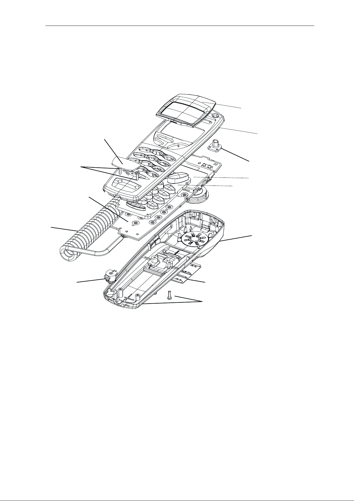
Handset – Mechanical Parts list
7
13
11
1
2
6
8
5
10
9
4
12
Item Part Description NMP – code
1 WINDOW 945 6568
2 A – COVER ASSY 9456610
3 B – COVER ASSY 9490099
4 SIM – DOOR ASSY 9490101
5 KEYMAT MODULE 979 4021
6 POWER KEY 979 0309
7 OEM LOGO (blank) 9430167
8 LCD MODULE 4850109
9 MIC BOOT ASSY 514 0115
10 CURLY CORD 978 0223
11 PCB ASSY 9854369
12 SCREW 629 0011
13 TYPE LABEL ROLL 937 0403
3
Issue 1 10/99
Page 3
Page 4
NME–3
PAMS
Mechanical Parts Assembly Instructions
Handset – Assembly Instructions
NOTE: WEAR GLOVES DURING THE
ENTIRE ASSEMBLY PROCESS
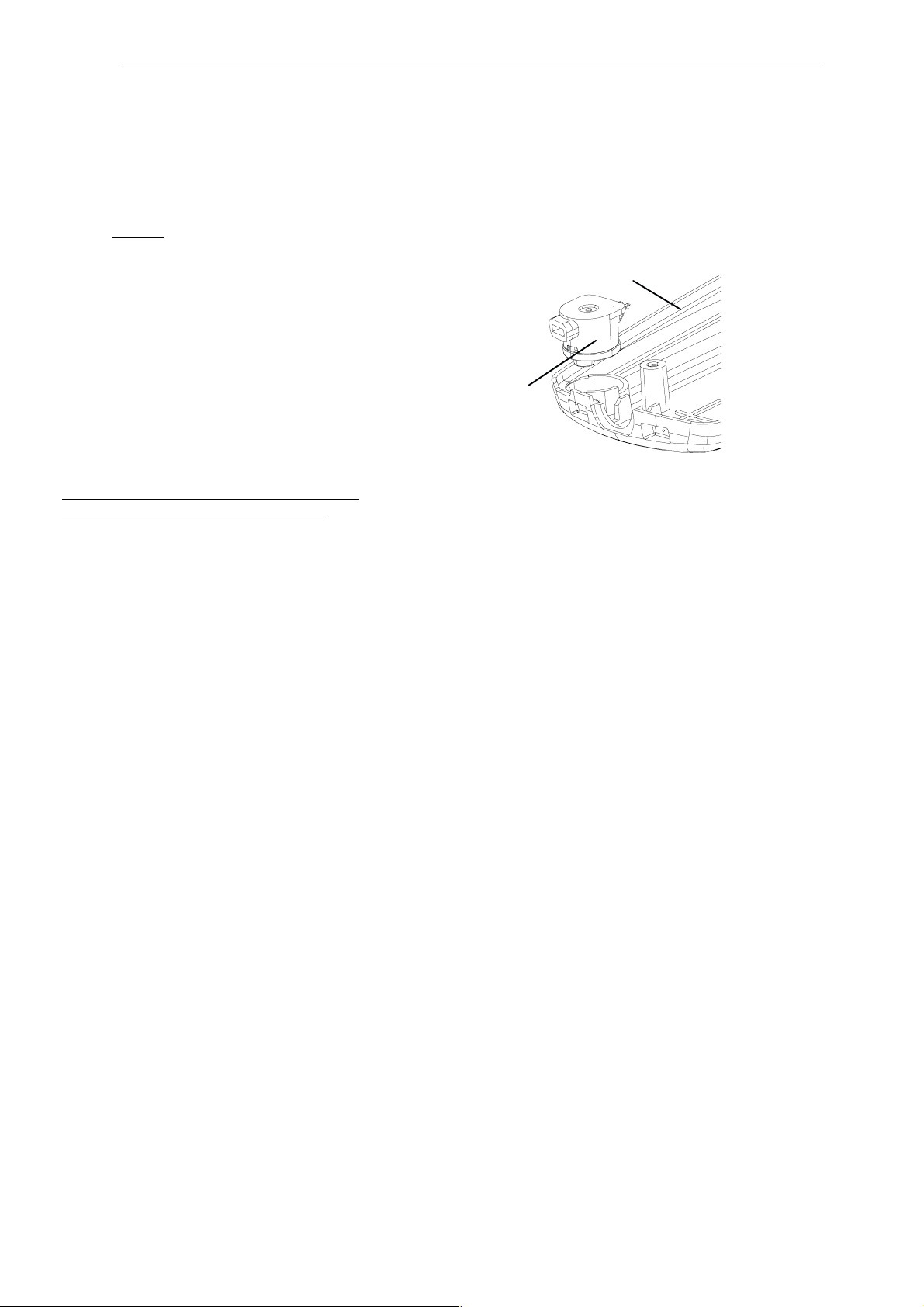
B – COVER SUB ASSEMBLY
• B – cover (3) and A – cover to assembly jig
• Press mic. Boot assy (9) into B–cover (3)
NOTE: SPEAKER ASSY IS UL TRASONIC
WELDED TO THE B–COVER
Technical Documentation
3
9
Page 4
Issue 1 10/99
Page 5
PAMS
NME–3
Technical Documentation
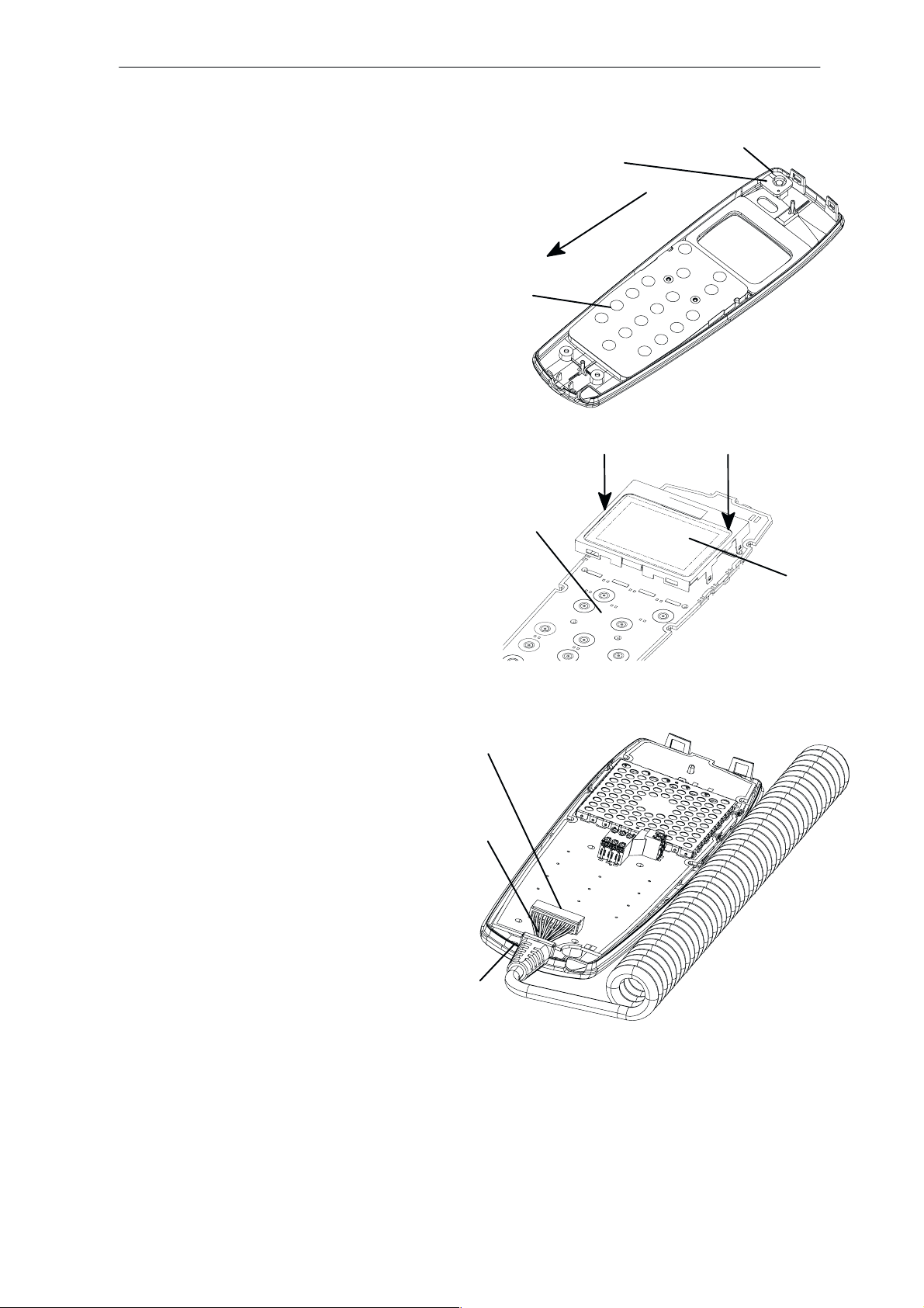
A – COVER PRE ASSEMBLY
• Power key (6) to A – cover
(ensure, that both coding pins fit into
the power key)
• Keymat (5) to A – cover
(do not touch contact area)
• Clean contact pads of keymat module with compressed air in the direction of the arrow
PCB SUB ASSEMBL Y
• Check the LCD module version (Minna or
Dude)
• Check that there is no rest at the PCB larger
ca.0.2mm
Mechanical Parts Assembly Instructions
6
CODING PINS
5
FF
12
• Fit LCD module (8) to the PCB assy (12)
• Check that all five LCD frame snappers fit
accurately into the PCB
• The curly cord (10) plugs into the PCB assy.
connector (12) – clamp it into place
• LCD protection foil off
• Clean PCB contact pads and LCD with com-
pressed air
• PCB (12) to A – cover (2)
• Strain relief of curly cord (10) to
A – cover, ensure it is fitted the right way
• The curly cord to the right side curls upwards
• Clean contact areas compressed air
8
12
10
2
Issue 1 10/99
Page 5
Page 6

NME–3
PAMS
Mechanical Parts Assembly Instructions
FINAL ASSEMBL Y
• Fit the bottom side of the B – cover (3) to the A –
cover (2)
• Press B – cover to A – cover until it snaps home
firmly.
• 2 screws (13) trough B – cover
into A – cover domes
(400 rpm, 30Ncm)
Technical Documentation
2
3
13
Page 6
Issue 1 10/99
Page 7

PAMS
NME–3
Technical Documentation
• Turn unit over to the keymat side
• 2 screws (13) trough A – cover
into B – cover domes
(400 rpm, 30Ncm)
• Verify that A – and B – cover are properly closed by
checking that the gap between them is constant all
arround the Handset
• Clean window with compressed air
• Pull window adhesive protection foil off the A – cover
and ensure, that the adhesive foil does not lift at the
finger lift side.
• Press window (1) to A – cover, top side first
Mechanical Parts Assembly Instructions
13
GAP
1
• Press the window down till it clips home
• Press down the window to ensure fixation to B –
cover
• Attach protection foil to mounted window
Issue 1 10/99
Page 7
Page 8

NME–3
PAMS
Mechanical Parts Assembly Instructions
• Fit SIM – door (4) to the B – cover (till it firmly snap)
• Place type label to B – cover
• Pull OEM – logo (7) from the roll and stick it to the A
– cover
Technical Documentation
4
7
• Ensure that the logo fits completely in the recess
area
• Pack Handset into a plastic bag and bulk package
Page 8
Issue 1 10/99
Page 9

PAMS
NME–3
Technical Documentation
Mechanical Parts Assembly Instructions
Radio Unit – Mechanical Parts List
9
5
2
6
7
3
1
4
8
Item Part Description NMP Code
1 BOTTOM ENCLOSURE 9537041
2 TOP SHIELD ASSY 9490057
3 TOP ENCLOSURE ASSY 9490056
4 SIM GUIDANCE 9450588
5 SCREWS M3x8 (5 off) 6290091
6 SCREWS M3x8 (7 off) 6290091
7 SEALING LABEL 9380933
8 NME–3 TYPE LABEL 9370402
9 GM8B RF/BASEBAND MODULE 0201346
Issue 1 10/99
Page 9
Page 10

NME–3
PAMS
Mechanical Parts Assembly Instructions
Radio Unit – Assembly Instructions
PCB Complete
Guiding Pin
Guiding Pin
Bottom Enclosure
Level 0
Technical Documentation
Operation:
Mount PCB in Bottom Enclosure
To check:
1. check that cutting rest is not bigger than 0.2mm
2. PCB positioned by guiding pins (press down until peak of guiding pin
aligns upper surface of PCB
3. Do not touch components
3
2
1
Screw M3x8
Bottom Enclosure
Level 1
Operation:
Fasten PCB with with 3 screws in the numbered order : 1–3
(torque : 63 Ncm, speed 400–1200rpm)
Page 10
Issue 1 10/99
Page 11

PAMS
NME–3
Technical Documentation
Level 2
Mechanical Parts Assembly Instructions
4
5
Screw M3x8
Bottom Enclosure
Operation:
Fasten PCB and PA with 2 screws in the numbered order : 4+5
(torque : 63 Ncm; speed 400–1200 rpm)
9
12
6
8
10
Top Shield Assy
7
11
Bottom Enclosure
Level 3
Operation:
1. Mount Top Shield assembly
2. Fasten 7 screws in the numbered order: 6–12
3. (torque: 63 Ncm; speed 400–1200 rpm)
4. Clean inside with compression air
5. Check guiding pins
6. Check gasket pins
Issue 1 10/99
Page 11
Page 12

NME–3
PAMS
Mechanical Parts Assembly Instructions
rotate into snaps
Technical Documentation
Top Enclosure Assy
Sealing Label
assemble ribs
3 recesses
SIM Guidance
Type Label
Level 4
Operation: (in Order)
1. Assemble SIM Guidance to Bottom Enclosure by jig.
2. Add the sealing label
3. Assembling Top Enclosure
recesses marked above. Rotate Top Enclosure until it snaps on the other side).
Add the type label making sure that the label lies in the recess area.)
( assemble ribs on inside of Top Enclosure to the 3
Level 5
To check:
existence of Data Cover
to put RU in plastic bag
Page 12
Data Cover
Issue 1 10/99
Page 13

PAMS
NME–3
Technical Documentation
Mechanical Parts Assembly Instructions
Cradle –Mechanical Parts List
Item Part Description NMP Code
1 A COVER 9451519
2 B COVER 9451520
3 PUSH – RIGHT 9451504
4 PUSH – LEFT 9451522
5 SPRING PUSH 6400063
6 SLIDER 9460309
7 SPRING SLIDER 6400109
8 HOOK – RIGHT 9451501
9 HOOK – LEFT 9451521
10 SPRING HOOK – RIGHT 6400105
11 SPRING HOOK – LEFT 6400107
12 MAGNET 6490017
13 SCREW COVER 9451505
14 SCREW T6x8 (2 off) 6293005
15 LABEL 9380535
16 MOUNTING PLA TE 9460310
Issue 1 10/99
Page 13
Page 14

NME–3
PAMS
Mechanical Parts Assembly Instructions
[This page intentionally left blank]
Technical Documentation
Page 14
Issue 1 10/99
 Loading...