

Page 1

Programme’s After Market Services
NME–3 Series Transceivers
Installation instructions
Issue 1 10/99
Page 2

NME–3
PAMS
Installation instructions
Technical Documentation
Contents
Introduction 3. . . . . . . . . . . . . . . . . . . . . . . . . . . . . . . . . . . . . . . . . . . . . . . . . . . . . .
Unpacking 4. . . . . . . . . . . . . . . . . . . . . . . . . . . . . . . . . . . . . . . . . . . . . . . . . . . . . . .
Component Parts 5. . . . . . . . . . . . . . . . . . . . . . . . . . . . . . . . . . . . . . . . . . . . . . . .
Mounting Bracket MBE–2 5. . . . . . . . . . . . . . . . . . . . . . . . . . . . . . . . . . . . . .
Handset Cradle CRD–8 5. . . . . . . . . . . . . . . . . . . . . . . . . . . . . . . . . . . . . . . .
Mounting Plate and Swivel Mounting Plate HHS–1 5. . . . . . . . . . . . . . . . .
System Cable SCM–5 and Vehicle Installation Cable DKS–7 5. . . . . . . .
Handsfree Microphone HFM–15 and Handsfree Speaker HFS–10 6. . .
External Mobile Antenna (not supplied) 6. . . . . . . . . . . . . . . . . . . . . . . . . . .
Installation 6. . . . . . . . . . . . . . . . . . . . . . . . . . . . . . . . . . . . . . . . . . . . . . . . . . . . . .
Power Distribution 8. . . . . . . . . . . . . . . . . . . . . . . . . . . . . . . . . . . . . . . . . . . . .
Car Radio Muting (XCRM) 9. . . . . . . . . . . . . . . . . . . . . . . . . . . . . . . . . . . . . .
Page No
Ignition Sense (IGNS) 10. . . . . . . . . . . . . . . . . . . . . . . . . . . . . . . . . . . . . . . . . .
Power Antenna Control (ANTC) 11. . . . . . . . . . . . . . . . . . . . . . . . . . . . . . . . .
Testing 11. . . . . . . . . . . . . . . . . . . . . . . . . . . . . . . . . . . . . . . . . . . . . . . . . . . . . . . . . .
List of Figures
Figure 1. Equipment listing diagram 4. . . . . . . . . . . . . . . . . . . . . . . . . . . . . . . .
Figure 2. Reducer 9. . . . . . . . . . . . . . . . . . . . . . . . . . . . . . . . . . . . . . . . . . . . . . . .
Figure 3. Connection – Radio Muting 10. . . . . . . . . . . . . . . . . . . . . . . . . . . . . . .
Figure 4. Connection – Power Antenna Control 11. . . . . . . . . . . . . . . . . . . . . .
Page 2
Issue 1 10/99
Page 3

PAMS
NME–3
Technical Documentation
Introduction
This installation guide has been prepared to provide the basic information
necessary to install mobile phone. This guide is not intended to be definitive, because different types and models of vehicle will require different
installation work. The information given is for general guidance only.
The terms of warranty demand that this mobile phone be installed by an
experienced installation facility. An end user should never attempt to install
this mobile phone without professional assistance as the installation requires special tools and knowledge.
Please refer to the phone’s user guide for instructions on the phone’s operation, care and maintenance, including important safety information.
Note: Read the warnings below before beginning the installation procedure.
WARNINGS
1. ENSURE THAT THE VEHICLE BATTERY IS DISCONNECTED
BEFORE YOU START THE INSTALLATION PROCEDURE, AND
THAT IT REMAINS DISCONNECTED DURING THE PROCEDURE.
Installation instructions
2. DO NOT SMOKE OR USE OPEN FLAMES WHEN WORKING
NEAR THE VEHICLE’S FUEL SYSTEM.
3. ENSURE THAT ELECTRICAL CABLES, HYDRAULIC LINES
AND FUEL LINES ARE NOT DAMAGED DURING INSTALLATION.
4. ENSURE THAT NORMAL CONTROL AND OPERATION OF THE
VEHICLE IS NOT IMPAIRED BY THE INSTALLATION, PARTICULARLY THE BRAKES AND STEERING.
5. ALTHOUGH ELECTRONIC SPEED CONTROL, ABS ANTI–LOCK
BRAKE AND FUEL INJECTION SYSTEMS ARE RELATIVELY IMMUNE TO MALFUNCTION CAUSED BY NEARBY RADIO
TRANSMISSIONS, SHOULD YOU EXPERIENCE FALSE OPERATION OF THESE SYSTEMS OR BE IN ANY DOUBT WHATSOEVER AS TO THEIR FUNCTIONALITY, PLEASE CONSULT THE VEHICLE DEALER.
6. THE MOBILE PHONE IS SUITABLE FOR USE ONLY IN VEHICLES WITH A 11..16 V NEGATIVE GROUNDING. USE ON
OTHER SUPPLY VOLTAGES OR ALTERNATIVE POLARITY
WILL DAMAGE THE EQUIPMENT.
7. THE PHONE SHOULD NOT BE LEFT SWITCHED ON FOR EX-
Issue 1 10/99
TENDED PERIODS WITHOUT RUNNING THE VEHICLE’S ENGINE. FAILURE TO COMPLY COULD DRAIN THE VEHICLE’S
BATTERY.
Page 3
Page 4
NME–3
PAMS
Installation instructions
Unpacking
Carefully unpack the equipment and ensure that the following items are
present.
Technical Documentation
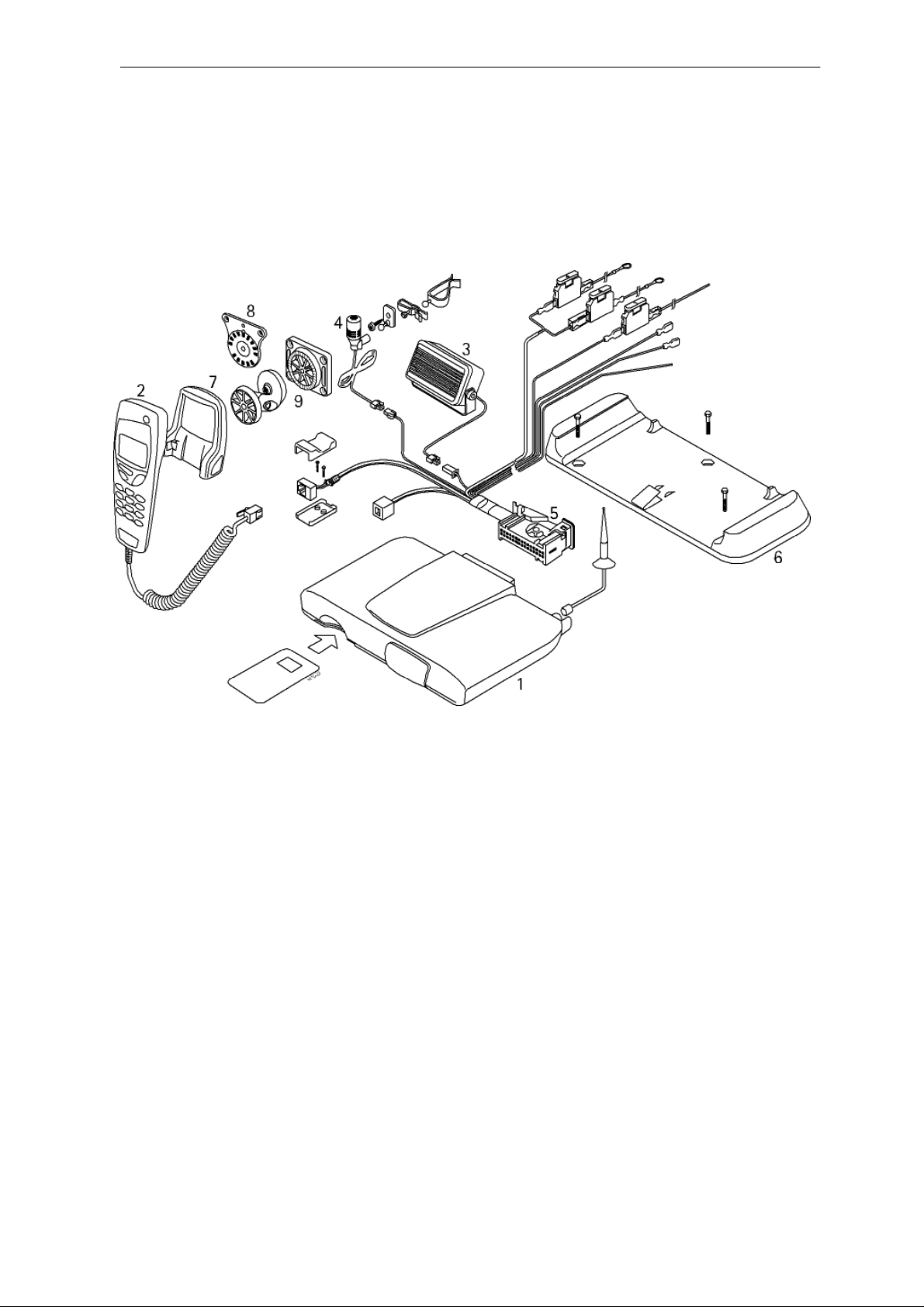
Figure 1. Equipment listing diagram
Item/Product Name: Type: Remarks: Code:
1. Transceiver NME–3 0600128
2. Handset RTE–2HJ 0640102
3. Handsfree speaker HFS–10 (Molex type conn) 0692006
4. Handsfree microphone HFM–15 (Molex type conn) 0630236
5. System cable +bracket SCM–5K 0730173
6. Mounting bracketcomplet MBE–2 (w/3 screws) 9457320
7. Handset cradle CRD–8 0650028
8. Mounting plate CRD–8 –––– 9460310
9. Swivel mount HHS–9 (w/5 screws) 0620037
Page 4
Issue 1 10/99
Page 5

PAMS
NME–3
Technical Documentation
Component Parts
Mounting Bracket MBE–2
The mounting bracket MBE–2 shall be installed using three screws. The
bracket itself can to a certain degree compensate for unevenness of the
mounting surface. However, should additional spacers be required, two
different types are supplied with the bracket.
The transceiver may be installed in the bracket in two ways: either by sliding the transceiver into the bracket or by vertically inserting the transceiver
from the top.
Handset Cradle CRD–8
The cradle CRD–8 acts as a holder for the handset. The cradle is attached to the vehicle interior using the mounting plate or swivel mount
HHS–9.
Installation instructions
Mounting Plate and Swivel Mounting Plate HHS–1
This is a fixed position mounting plate; HHS–1 is a swivel mounting plate
which allows adjustable fixing of the CRD–8 cradle. Both mounting plates
are interchangeable.
System Cable SCM–5 and Vehicle Installation Cable DKS–7
The system cable connects the phone to the vehicle supply and accessories.
The power wires red (+) and black (–) shall be routed to the battery itself
(alternatively to the main distribution point of the vehicles fuse box) both +
and – must be fuse protected (3 A).
The blue ignition sense (IGNS) wire is connected to +12 V voltage controlled by the vehicle’s ignition key via 1A fuse. The ignition sense can utilize voltages up to 24 V, see section ”Ignition Sense”
The yellow wire is used for car radio muting (XCRM). The line goes down
to 0 volts during a call. The maximum sink current is 100 mA, hence the
actual muting operation may have to by done using an auxiliary relay, or a
muting unit provided by the manufacturer, see ”Car Radio Muting”.
The orange wire is used for motor antenna (ANTC). The voltage in this
output is +12 V whenever the phone is on. The maximum sink current is
180 mA, so the actual motor antenna operation may have to be done by
using an auxiliary relay, see ”Power Antenna Control”.
The RJ45 handset connector is non–assembled. Locate the correct position, fasten the bottom shell with two screws, place the connector and
cable and click the top on.
Issue 1 10/99
Page 5
Page 6

NME–3
PAMS
Installation instructions
Technical Documentation
Handsfree Microphone HFM–15 and Handsfree Speaker HFS–10
The safest and easiest way to have call while driving is use the handsfree
option. The system consist of two components, the microphone HFM–15
and loudspeaker HFS–10.
The microphone needs to be as close to the drivers mouth as possible
and attached to a surface that is mechanically quiet. The microphone connects to the system cable MIC molex connector but avoids the fan output
area in order to maintain the quality of audio.
The loudspeaker should be mounted at least 3 ft/1 m away from the
handsfree microphone to avoid acoustic feedback. The loudspeaker connects to the system cable SPEAKER molex connector.
External Mobile Antenna (not supplied)
The phone is designed to operate with a high quality external antenna.
However, due to many different types of antennas being available, an antenna is NOT included as part of car kits. Please, consult the dealer to find
out which is the most suitable antenna type for your installation.
Installation
There are some important aspects that require special attention in positioning mobile phone accessories.
The positioning of the handset holder is the most important factor when
trying to achieve the most comfortable position for the user. The location
of the holder should be selected so that the visibility of the handset’s display is good under all lighting conditions, but not so that the driver’s attention is easily distracted. The holder should be located so that the driver
can easily reach the keypad. Under no circumstances should the holder
prevent the driver from controlling or operating the vehicle in any way or
observing traffic.
The phone mounting bracket may be installed in a variety of places including:
. centre console below dash on either left or right side
. any available shelf above or below dash
. vacant DIN slot (consumes only half the height of a DIN slot)
. under seats
. trunk
Page 6
Ensure the location does not subject the phone to moisture or mechanical
pressure or where there isn’t adequate amount of air for cooling (under
the carpet, etc.).
Issue 1 10/99
Page 7

PAMS
NME–3
Technical Documentation
The handsfree microphone can be installed on the driver’s sunvisor or the
A–pillar. Ensure the microphone is as close to the driver’s mouth as possible, and attached to a surface that is mechanically quiet. The microphone should be mounted at least 3 ft/1 m away from the handsfree unit
speaker to avoid acoustic feedback. The loudspeaker isn’t so sensitive for
vibrations, thus it can be located more freely. The main idea is to optimize
two requirements: The driver should hear the signal from the loudspeaker
without any special efforts, but attenuation between loudspeaker and microphone should be as high as possible, i.e. they must ”look” in other
directions in order to minimize the acoustic feedback.
Ensure cables are routed as far away as possible from the vehicle’s electronic systems (refer to WARNINGS). Also ensure cables are not subjected to undue mechanical stress e.g. under seats or against sharp
edges.
The most important component of the installation is the antenna. The
location of the antenna as well the quality of the antenna and its installation have a considerable influence to the overall performance of the whole
system. Therefore it is necessary to emphasize some aspects, which too
often have caused unnecessary service work.
Installation instructions
The best place for the antenna is the rooftop. The overall performance of
a rooftop antenna is clearly superior to any other antenna type or location.
The Antenna shall be mounted in a position such that no part of human
body will normally rest too close to any part of the antenna unless there is
an intervening metallic screen, for example, the metallic roof.
• highest place in the car
• proper ground place
• omni–directional radiation pattern
• minimum risk for disturbances
• user safety
After drilling the hole for the antenna remember to clean the hole from the
drilling swarf, so that surface is even. This is needed in order to ensure
proper and reliable connection between the ground plane and the antenna. After cleaning it is advised to apply some rust–proofing compound to
the hole.
Mount the base of the antenna tightly in position. Consult the antennas
manual for determining the maximum bending angle before attempting
any bending operation.
To avoid drilling a hole in the vehicle’s bodywork, a glass–mounted antenna can be chosen and located on the rear window of the vehicle.
Issue 1 10/99
Page 7
Page 8

NME–3
PAMS
Installation instructions
Try to route the antenna cable so that possible sources of disturbances
are avoided, as well anti–skid brake systems. The shorter the antenna
cable, the smaller the attenuation, and the better the performance of the
antenna. The antenna coupler should always be connected to the antenna
via a non–radiating cable (e.g. coax).
Most of the antennas today have adapted the mini–crimp connector system which eliminates the need for special crimping tools and connectors.
If however the purchased antenna has traditional connectors, use only
proper connectors and tools. The phone uses mini a UHF female type antenna connector for reasons of reliability and attenuation.
All installations should take into account any special requirements of the
customer. However, should the customer require an installation that is illegal or unsafe these facts must be pointed out to the customer and a policy
of non–compliance adopted.
Power Distribution
The main supply for mobile phone is obtained from the vehicle battery, the
supply voltage may vary between 11,8 and 16 volts. Both the positive voltage and the grounding are taken directly from the battery, unless the vehicle has other main voltage than +12 V. This minimizes the risk of disturbances from or to the telephone as well as guarantees loss–free power
distribution.
Technical Documentation
The connections to the battery should be carried out with care. Both the
negative and positive leads have 3A fuses, which must always be used. If
a fuse blows, replace it only with the same type and size fuse.
The power cables should be routed so that possible sources of disturbances are avoided. Also ABS–sensors and like should be avoided as far
as possible.
If the vehicle has +24 V electrical system (trucks, all–terrain vehicles ,
etc.), an external voltage reducer must be used. Since the properties of
the reducer are critical, it is recommended to use a reducer supplied by
the manufacturer. This reducer has good protections against transients
produced by vehicles electrical system and it is also capable of maintaining stabile output during rapid changes in load current.
Page 8
Issue 1 10/99
Page 9

PAMS
NME–3
Technical Documentation
Some vehicles have a main switch (e.g. gas trucks), which separates the
vehicles chassis from the negative lead of the battery. Do under no circumstances pass this switch, i.e. the grounding of the reducer must be
taken from the body of the vehicle, NOT
Installation instructions
Figure 2. Reducer
directly from the battery.
WARNING : DO NOT INSTALL REDUCER
– To engine compartment
– Where there isn’t adequate amount of air for cooling (under the
carpet, etc.)
– Where there is risk of moisture (condensed water, etc.)
Car Radio Muting (XCRM)
The phone offers a feature that can mute the car radio automatically during a conversation. This feature is convenient and provides for safer
handsfree operation. The car radio muting feature based on grounded
line, so it means that in standby, the yellow wire (XCRM) is not grounded
and car radio works normally, but during a call, line is grounded and car
radio is muted. The maximum load that this line can handle is 100 mA.
Note: an auxiliary relay or muting unit must be used when the car radio doesn’t have a
mute feature available.
Issue 1 10/99
Page 9
Page 10

NME–3
Installation Instructions
When a relay is used, connect of series with the car radio main supply. A
100 mA fuse should be used to protect the XCRM output in event of a
short circuit. Some radios have separate supplies for amplifiers and motors, and another for memory backup purposes. Very often these radios
also have a secret code system, which activates itself if a break in the
memory supply is detected. Be careful when installing the relay not to
break the memory supply (usually marked ACC or +MEM), but to install
the relay in the main supply feed.
PAMS
Technical Documentation
CAR
RADIO
To XCRM line
(yellow wire)
Another possibility is to use a special muting unit (SR59), which mutes the
radio by connecting load resistors to the speaker lines of the car radio.
Four loudspeakers can be muted and the maximum permitted power is 20
watts per channel. The muting unit can also be used as a relay to cut the
main supply feed of the car radio.
Ignition Sense (IGNS)
The ignition sense feature prevents the transceiver from draining the car
battery by executing an auto power off 45 sec.– 24 houres after the ignition key has been turned off (unless the Auto Power Off feature is deactivated).
87A
30
87
85
Figure 3. Connection – Radio Muting
86
Fuse 100 mA
not supplied)
12 V d.c.
Supply for
car radio
12 V d.c.
The blue wire of the power cable is used for the ignition sense feature.
The use of IGNITION SENSE is recommended to prevent accidental
draining of the car’s battery. The wire is connected via a 1 A fuse to a 12
volt potential that is controlled by the ignition key. Do not connect it directly
to the high voltage sections of the ignition circuit. If the feature is not
used, just leave the wire unconnected, and protect the end of the cable
with insulating tape.
Page 10 Amendment 11 / 99
Page 11

PAMS
NME–3
Technical Documentation
Power Antenna Control (ANTC)
The orange wire of the system cable (ANTC) may be used to control different devices on and off. The voltage in this output is +12 V whenever the
phone is on. If the phone is turned off, the voltage disappears. The maximum output current is 180 mA, therefore for example motorized antenna
must be controlled via a relay, see picture below.
Bosch P/N 0–332–204–150 12
V, 30 A. SPDT
Supply for de
From ANTC line
vice
(orange wire)
Fuse 180 mA
(
not supplied)
Installation instructions
CONTROLLED
DEVICE, e.g.
MOTOR AN TENNA
Testing
Once installed, the equipment should be tested to ensure that it is operating satisfactorily and that the position of the units does not impair on the
driver’s ability to control and operate the vehicle in any way.
Use the phone to make a call when the vehicle is parked with the engine
running. During the call, switch off the engine. Ensure that the phone is
operational with the engine running and with the engine switched off. For
operating information refer to the ’User Guide’ supplied with the phone.
Figure 4. Connection – Power Antenna Control
Issue 1 10/99
Page 11
Page 12

NME–3
PAMS
Installation instructions
Technical Documentation
[This page intentionally left blank]
Page 12
Issue 1 10/99
 Loading...