

Page 1

Programmes After Market Services (P.A.M.S.)
Technical Documentation
NME–2A SeriesTransceivers
Service Software
Instructions
Original 08/97
Page 2

NME–2A
P.A.M.S.
Service Software Instructions
AMENDMENT RECORD SHEET
Amendment
Number
Date Inserted By Comments
08/97 Original
Technical Documentation
Page 2
Original 08/97
Page 3

P.A.M.S.
NME–2A
Technical Documentation
Service Software Instructions
Contents
General 5. . . . . . . . . . . . . . . . . . . . . . . . . . . . . . . . . . . . . . . . . . . . . . . . . . . . . . . . .
Required Servicing Equipment 5. . . . . . . . . . . . . . . . . . . . . . . . . . . . . . . . . . . . .
Mechanical Connections 6. . . . . . . . . . . . . . . . . . . . . . . . . . . . . . . . . . . . . . . . . .
Starting 8. . . . . . . . . . . . . . . . . . . . . . . . . . . . . . . . . . . . . . . . . . . . . . . . . . . . . . . . .
PCLocals Menu Structure, Main Menu 9. . . . . . . . . . . . . . . . . . . . . . . . . . .
PCLocals Menu Structure, Testing and Adjustment Menu 10. . . . . . . . . . .
PCLocals Menu Structure, ME Short Code Memory 11. . . . . . . . . . . . . . . .
Using Menus 12. . . . . . . . . . . . . . . . . . . . . . . . . . . . . . . . . . . . . . . . . . . . . . . . . . . .
Help Functions 12. . . . . . . . . . . . . . . . . . . . . . . . . . . . . . . . . . . . . . . . . . . . . . . .
Text Editing Windows 13. . . . . . . . . . . . . . . . . . . . . . . . . . . . . . . . . . . . . . . . . .
PCLocals Menu Commands 15. . . . . . . . . . . . . . . . . . . . . . . . . . . . . . . . . . . .
Page No
1 – PC Setup 16. . . . . . . . . . . . . . . . . . . . . . . . . . . . . . . . . . . . . . . . . . . . . .
2 – Initialize Phone 18. . . . . . . . . . . . . . . . . . . . . . . . . . . . . . . . . . . . . . . . .
3 – Testing and Adjustments 18. . . . . . . . . . . . . . . . . . . . . . . . . . . . . . . . .
3.1 – RF Controls 19. . . . . . . . . . . . . . . . . . . . . . . . . . . . . . . . . . . . . . . . . .
3.2 – Adjustments 22. . . . . . . . . . . . . . . . . . . . . . . . . . . . . . . . . . . . . . . . . .
3.3 – Call Simulation 32. . . . . . . . . . . . . . . . . . . . . . . . . . . . . . . . . . . . . . .
3.4 – Internal Audio Loop 33. . . . . . . . . . . . . . . . . . . . . . . . . . . . . . . . . . . .
3.5 – External Audio Loop 34. . . . . . . . . . . . . . . . . . . . . . . . . . . . . . . . . . .
3.6 – Logic Controls 35. . . . . . . . . . . . . . . . . . . . . . . . . . . . . . . . . . . . . . . .
3.7 – MCU Selftests 36. . . . . . . . . . . . . . . . . . . . . . . . . . . . . . . . . . . . . . . .
3.8 – Set MCU Start–up Self–tests 37. . . . . . . . . . . . . . . . . . . . . . . . . . .
4 – ME Memory Functions 38. . . . . . . . . . . . . . . . . . . . . . . . . . . . . . . . . . .
4.1 – ME Short Code Memory 39. . . . . . . . . . . . . . . . . . . . . . . . . . . . . . . .
4.2 – User Settings and Values 41. . . . . . . . . . . . . . . . . . . . . . . . . . . . . . .
4.3 – Write HW Version 43. . . . . . . . . . . . . . . . . . . . . . . . . . . . . . . . . . . . .
4.4 – Product Profile Settings 43. . . . . . . . . . . . . . . . . . . . . . . . . . . . . . . .
4.5 – IMEI Edit 44. . . . . . . . . . . . . . . . . . . . . . . . . . . . . . . . . . . . . . . . . . . . .
4.6 – IMEI Transfer 44. . . . . . . . . . . . . . . . . . . . . . . . . . . . . . . . . . . . . . . . .
4.7 – Set UI and SCM factory Values 45. . . . . . . . . . . . . . . . . . . . . . . . .
4.8 – Set Factory Values 45. . . . . . . . . . . . . . . . . . . . . . . . . . . . . . . . . . . .
4.9 – Microphone Setting 45. . . . . . . . . . . . . . . . . . . . . . . . . . . . . . . . . . . .
5 – Power–up Selftests 46. . . . . . . . . . . . . . . . . . . . . . . . . . . . . . . . . . . . .
6 – SW and HW Versions 47. . . . . . . . . . . . . . . . . . . . . . . . . . . . . . . . . . .
7 – Phone Mode 49. . . . . . . . . . . . . . . . . . . . . . . . . . . . . . . . . . . . . . . . . . .
Original 08/97
Page 3
Page 4

NME–2A
P.A.M.S.
Service Software Instructions
Q – Quit 49. . . . . . . . . . . . . . . . . . . . . . . . . . . . . . . . . . . . . . . . . . . . . . . . . . .
Appendix I 50. . . . . . . . . . . . . . . . . . . . . . . . . . . . . . . . . . . . . . . . . . . . . . . . . . . .
Installing PCLocals service software on PC hard disk 50. . . . . . . . . . .
Appendix II 51. . . . . . . . . . . . . . . . . . . . . . . . . . . . . . . . . . . . . . . . . . . . . . . . . . .
Starting options for PCLocals service software 51. . . . . . . . . . . . . . . . .
Technical Documentation
List of Figures
Figure 1. Connection Diagram 6. . . . . . . . . . . . . . . . . . . . . . . . . . . . . . . . . . . .
Page No
Page 4
Original 08/97
Page 5

P.A.M.S.
NME–2A
Technical Documentation
General
The Service Software ”PCLocals” is specially designed to facilitate the
servicing of GSM cellular telephones.
The software can be used to control the phone according to the user’s
wish merely by entering commands via the keyboard of a PC/AT
connected to the phone.
This section refers to GSM PCLocals Version 1.0. To receive a free
upgrade, please follow the de–install instructions in Appendix I and send
the disk to Nokia Mobile Phones.
Required Servicing Equipment
– Computer: IBM PC/AT or compatible with one unused serial port
(COM1 or COM2)*), one parallel port (LPT1), hard disk recommended
– Operating System: DOS Version 3.2 or later
Service Software Instructions
– Display: Any 80–character text display
– PCLocals program, 3.5” disk (product code: 0774028)
5.25” disk (product code: 0774031)
– Software protection key PKD–1 (product code: 0750018)
– M2BUS adapter DAU–2 (product code: 0750006)
– Modular cable XCM–1 (product code: 4626131)
– RS–232 adapter, 9–to–25 pins (product code: 4626170)
– Service cable SCS–1 (product code: 0770010)
– Service box JBS–7 (product code: 0770015)
– Power connector PCS–1 (product code: 0730012)
– Audio cable ADS–1 (product code: 0730011)
– Mini UHF – BNC cable
*) Note:
Original 08/97
A number of PC’s of an older generation use the Intel, National
Semiconductor, or United Microelectronics IC 8250 as the serial port UART.
This is a comparatively inefficient circuit for current purposes and does not
necessarily support the M2BUS adapter at 9600 baud. The newer UART’s
NS16450 and NS16550AF of National Semiconductor offer solutions for
these problems.
Page 5
Page 6
NME–2A
P.A.M.S.
Service Software Instructions
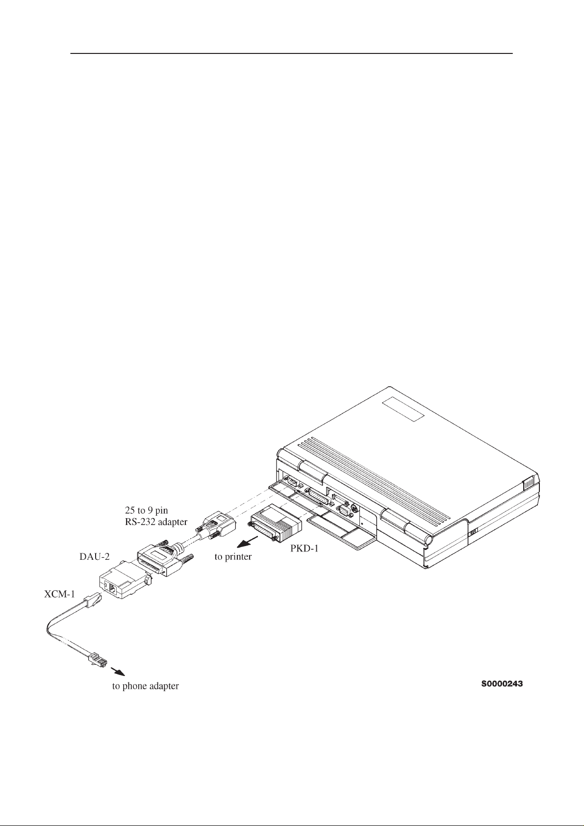
Mechanical Connections
Caution: Make sure that you have switched off the PC and the printer
before making connections !
Caution: Do not connect the PKD–1 key to the serial port. You may
damage your PKD–1 !
The software controls the phone via a separate adapter connected to the
serial port of the PC and to the telephone’s M2BUS (DAU–2 and XCM–1).
Attach the protection key PKD–1 to parallel port one (25–pin female
D–connector) of the PC. When connecting the PKD–1 to the parallel port
be sure that you insert the PC end of the PKD–1 to the PC (male side). If
you use a printer on parallel port one, place the PKD–1 between the PC
and your printer cable.
The PKD–1 should not effect devices working with it. If some errors occur
(errors in printing are possible) please try printing without the PKD–1. If
printing is OK without the PKD–1 please contact your dealer. We will offer
you a new PKD–1 in exchange for your old one.
Technical Documentation
Page 6
Figure 1. Connection Diagram
NOTE: When using a laptop to run PCLocals ensure the Powersave
function of the laptop is switched OFF.
Original 08/97
Page 7

P.A.M.S.
NME–2A
Technical Documentation
Connect the M2BUS adapter (DAU–2, item 11) to the serial port (25–pin
male D–connector). In case your PC (as AT types in general) has a 9–pin
serial port use the special connector adapter cable provided (item 8).
Attach one end of the SCS–1 service modular cable to the DAU–2
PC/M2BUS adapter and the other end to the phone data connector.
The RF cable should be connected between the RF connector of the
phone and the RF connector of the test equipment.
For audio testing connect the service cable, ADS–1, as follows:
– Connect a modular cable XCM–1 to system cable handset connector.
– Attach T–adapter to other end of the modular cable.
– Connect handset and audio cable ADS–1 into T–adapter.
– Attach EAR line of audio cable to AF INPUT of test equipment
– Attach MIC line of the audio cable to MOD GEN OUTPUT of test
equipment
Service Software Instructions
Original 08/97
Page 7
Page 8

NME–2A
P.A.M.S.
Service Software Instructions
Starting
Start the phone by pressing the power on button of the handset. Switch
PC power on.
To start the program on diskette, proceed as follows:
1. insert PCLocals diskette
into drive A: of your PC
2. log into drive A:
3. start NME2SERV.BAT and
run PCLocals
To start the program on hard disk (if installed), proceed as follows:
1. log into drive C:
Technical Documentation
type A: and press Enter
type NME2SERV
and press Enter
type C: and press Enter
2. start NME2SERV.BAT and
run PCLocals
type NME2SERV
and press Enter
Note: See installation instructions in Appendix I.
Note: For more information on PCLocals starting options, see
Appendix II.
The PCLocals software version can be seen on the screen. Press
the phone begins to scan the GSM channel. If the phone cannot find the
Esc
correct reference channel, press
to seeing the main menu.
Enter
;
Page 8
Original 08/97
Page 9

P.A.M.S.
NME–2A
Technical Documentation
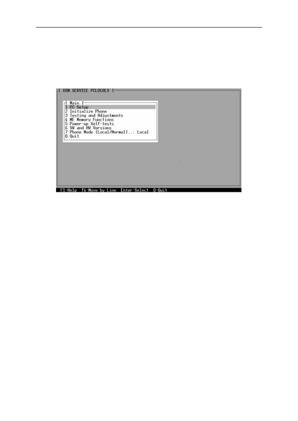
PCLocals Menu Structure, Main Menu
MAIN
1 PC Setup
2 Initialize Phone
3 Testing and Adjustment
4 ME Memory Functions
5 Power–up Self–tests
6 SW and HW Versions
7 Phone Mode (Local/Normal)..:Local
Q Quit
Service Software Instructions
PC Setup
1 Load New Setup
2 Save Current Setup
Testing and Adjustments
1 RF Controls
2 Adjustments
3 Call Simulation
4 Internal Audio Loop
5 External Audio Loop
6 Logic Controls
7 Run MCU Selftests
8 Set MCU Start–Up Self–tests
ME Memory Functions
1 ME Short Code Memory
2 User Settings and V alues
3 Product Profile Settings
4 Write HW Version
5 IMEI Edit
6 IMEI Transfer
7 Set UI and SCM Factory Values
8 Set Factory Values
9 Microphone setting
Power–up Selftests
MCU Internal Test......................: OK
MCU RAM BUS Test.................: OK
MCU IMEI Test...........................: OK
MCU ROM BUS Test:................: OK
MCU ROM DATA Test...............: OK
MCU ASIC BUS Test.................: OK
MCU ASIC Timer & IRQX Test.: OK
MCU ASIC Timer & NMI Test....: OK
MCU Audio Codec Test.............: OK
MCU DSP Code Download.......: OK
MCU EEPROM Checksum Test: OK
MCU Tests.................................: OK
Original 08/97
SW and HW Versions
MCU Internal SW Version.: 1.15 03–02–95 NM–2 (c) NMP.
MCU External SW Version: 1.87b 12–06–95 NME–2X (c) NMP.
DSP Internal SW Version..: ROM4 (LY)
DSP External SW Version.: G4.65CR
ASIC Version.....................: G–2
HW Version.......................: 0187
Production Number............: 12345
Warranty Information..........: 0405
Page 9
Page 10

NME–2A
P.A.M.S.
Service Software Instructions
Technical Documentation
PCLocals Menu Structure, Testing and Adjustment Menu
RF Controls
1 Actie Unit (TX/RX)............................: RX
2 TX Power Level................................: 15
3 Operation Mode (Burst/Continuous).: Burst
4 TX Data Type (0/1/Random).............: 1
5 Continuous Mode Channel...............: 60
6 Channel............................................: 60
7 Monitoring Channel...........................: 1
8 AGC..................................................: 81 dB
Adjustments
1 Continuous Mode Channel...........: 60
2 TX Power Tuning
3 TX I/Q Tuning
4 RSSI Calibration
5 AFC Diagram
6 Noise Sensitivity
Testing and Adjustments
1 RF Controls
2 Adjustments
3 Call Simulation
4 Internal Audio Loop
5 External Audio Loop
6 Logic Controls
7 Run MCU Selftests
8 Set MCU Start–up Self–tests
Call Simulation
1 TX Power Level........: 10
2 Channel....................: 60
3 Monitoring Channel 1: 1
4 Monitoring Channel 2: 1
5 Monitoring Channel 3: 1
6 Monitoring Channel 4: 1
7 Monitoring Channel 5: 1
8 Monitoring Channel 6: 1
Internal Audio Loop
1 Input (Int/Ext)......: Int
2 Output (Int/Ext)...: Int
3 Loop (On/Off).....: Off
External Audio Loop
1 Interface (HS/HF)....: HS
2 Make a Measurement
Logic Controls
1 LCD Test Display (1/2)............: 1
2 Car Radio Mute.......................: UNMUTED
Page 10
Set MCU Start–up Self–tests
1 ASIC BUS tests.................:Off
2 ASIC Timer & IRQX Test....:Off
3 ASIC Timer & NMI Test......: Off
4 Audio Codec Test...............: Off
Original 08/97
Page 11

P.A.M.S.
NME–2A
Technical Documentation
Service Software Instructions
PCLocals Menu Structure, ME Short Code Memory
ME Short Code Memory
Number: Name:
1:
2:
3:
4:
5:
6:
7:
8:
9:
10:
ME Memory Functions
1 ME Short Code Memory
2 User Settings and V alues
3 Product Profile Settings
4 Write HW Version
5 IMEI Edit
6 IMEI Transfer
7 Set UI and SCM Factory Values
8 Set Factory Values
9 Microphone Setting
User Setting and Values
1 Read from ME
2 Write to ME
3 Save to File
4 Read from file
5 Security ID
6 Master Code
7 Wake Up Message
Product Profile Settings
1 Italian Language........(On/Off): Off
2 Hungarian Language..(On/Off): Off
Original 08/97
Page 11
Page 12

NME–2A
P.A.M.S.
Service Software Instructions
Using Menus
All menu selections have a separate selection character in the first
column. This character is a number, a letter or a special ASCII character
(e.g., + or –). Menus have a fixed constant display structure, i.e. the texts
cannot be scrolled.
You can select a function from a menu in two different ways. The first way
is to press the key on the PC keyboard corresponding to the first character
of the line. The other way is to move the cursor from line to line using
arrow keys and make the selection with the
When you have made your selection the new menu or window will appear
on the PC screen. Every menu and window carries a name on the
topmost line. The name is the same as the selection in the previous menu
or window. When the new menu is activated the old one will disappear.
When a window is activated the selectable keys are seen in the window.
Windows may have a scrolling or a constant display.
Technical Documentation
Enter
key.
Common control key symbols are always seen on the help line (line 25)
and the keys may be used always when seen on the last line.
With a window or menu active the
out the window or menu and bring the previous menu or window to the
display. The
menu. When editing data the
edition the
Help Functions
The last line (line 25) will always list the special keys which can be used.
The help key
When the help key is used a new window will appear on the screen. The
new window contains a text that describes the function over which the
cursor was when the help key was used. The
back to the menu and the help window will disappear.
Esc
key is pressed to quit selection, put
Esc
key doesn’t have any effect when it is used with the main
Esc
key can be used as interrupt key. During
Enter
key is used as exit key.
F1
can be used anytime when the menu is on the display.
Esc
key will move the cursor
Page 12
Original 08/97
Page 13

P.A.M.S.
NME–2A
Technical Documentation
Text Editing Windows
When you have made a selection which needs some additional
information, the basic text editing window is activated.
The text editing window may have one or more editing lines. The length of
the line varies depending on the function. When the window is activated
the text which was previously in that window (default text) reappears on
the screen.
The following key selections are possible:
Key Function
Enter
Esc
Selects the text in the window; the editing window is turned off.
The selected text will be the default text of the selection.
Interrupts editing; the previous menu is shown and the default
text won’t be updated.
Service Software Instructions
Ins
← Arrow keys (right shift and left shift) move the cursor. The
Home
End
BS
Toggles the editing mode between insert and overstrike modes.
The last line of the screen tells the current editing mode. When
editing ends the editing mode is retained and same mode
is used again when editing text.
cursor moves as if the lines were positioned one after another.
For instance right shift causes the cursor to move from the last
column of the first line to the first column of the second line. If
the right shift is used and the cursor is at the last position of
the last line, the cursor is not moved. Similarly, the cursor does
not move with the left shift key when it is at the first position of
the first line.
Moves the cursor to the start of the text.
Moves the cursor to the end of the text.
The backspace key has two different meanings depending on
the editing mode;
• When the overstrike mode is activated the
moves the cursor back and changes the character under the
cursor into a space. If the cursor is at the first position of the
first line nothing happens.
Backspace
key
Original 08/97
• When the insert mode is activated the
the cursor back and deletes the character under the cursor so
that all characters after the deleted character are moved one
position back. If the cursor is at the first position of the first line
nothing happens.
Backspace
key moves
Page 13
Page 14

NME–2A
P.A.M.S.
Service Software Instructions
Del
F1
F4
Has also two different meanings depending on the editing
mode;
• When the overstrike mode is activated the
the character under the cursor into a space and moves the
cursor for ward. If the cursor is at the last editing position of the
last line nothing happens.
• When the insert mode is activated the
character under the cursor so that all characters after the
removedcharacter are moved one position back. If the cursor
is at the last editing position of the last line nothing happens.
Function key number 1 activates the help window.
Clears text in the editing window.
Technical Documentation
Del
key changes
Del
key removes the
Page 14
Original 08/97
Page 15
P.A.M.S.
NME–2A
Technical Documentation
PCLocals Menu Commands
When you start the PCLocals program, the main menu can be seen on the
screen. There are eight main functions;
Service Software Instructions
The phone should be in the local mode for the third and fourth functions.
(After the program has started the phone automatically assumes the GSM
mode). You can change phone mode by choosing function ”7 – Phone
mode”.
The number identifier of each title refers to a main– and a sub–menu item.
E.g., in
”3 – Testing and adjustment” of the main menu. The second number (1)
refers to the first block ”1 – RF control” of the testing and adjustment
menu. The third number (2) refers to the second block ”2 – TX power
level” of the RF control menu.
3.1.2 TX Power Level;
the first number (3) refers to the third block
Original 08/97
Page 15
Page 16

NME–2A
P.A.M.S.
Service Software Instructions
1 – PC Setup
Technical Documentation
When save setup is selected the basic text window is made and the
program asks setup file name. Enter the file name or use the default
with the
mentioned menus or windows) and parameters:
– Command line parameter value for COM port selection
– RF Controls menu
– Call Simulation
• All selections which are not same as in the RF Controls menu
– Tuning parameters (PC default values; no effect on EEPROM
• TX power coefficients
• Power connection diagram
– Run MCU Self–tests
• All selections
Next selections are not saved to setup file:
– Values which are asked from MS
Enter
key. The saved information includes all next selections (on
• All selections
values)
.
Save
Page 16
• AFC value
– Main Menu
• Phone Mode (Start value = Normal)
Original 08/97
Page 17

P.A.M.S.
NME–2A
Technical Documentation
– PC Setup menu
• Default name for setup file
(Start value = NME_2.CON)
– Internal audio loop:
• input (Start value = Int)
• output (Start value = Int)
• loop (Start value = Off)
– External audio loop:
• interface (Start value = HS)
– Logic controls
• Car Radio Mute, CRM (Start value = Unmuted)
• LCD Test Display (Start value = 1)
Load function generates same kind of basic text window as save function
and asks setup file name. When the name has been give and
has been used the file is loaded and all previously told selections and
parameters are replaced with the values taken from the file. This has
same effect as command line parameter –f.
Service Software Instructions
Enter
key
Both save file and load file function has default name which is previously
used name. For instance if setup was saved to file CONF.CON and load
Enter
function is activated the default value is CONF.CON. If only
pressed default value is used. If
interrupted. If invalid DOS filename is used or there isn’t load file with
given name error message will come to the display.
If phone mode had Local value before setup file loading, the mode is
changed to Normal in the phone by special Normal mode message and all
functions caused by the change are done. If mode was Normal before
new setup, all needed setup file settings are sent to MS as in the previous
case, but phone mode change command is not sent to MS. Note next
exception: If phone mode is Normal and interface is M2BUS and
communication port is different in the setup file than the value before file
loading, then also Normal phone mode message has to be sent to MS.
Every time when phone mode change message from Local to Normal is
received by MS it makes reset to the whole MS.
Esc
key is used the function will be
key is
Original 08/97
Page 17
Page 18

NME–2A
P.A.M.S.
Service Software Instructions
2 – Initialize Phone
With this function you can initialize the phone to accept M2BUS
commands from the PC. This function should be used right after the
phone is connected to the PC and powered up.
The initialization function performs the following sub–functions:
– MBUS registration
– Test mode message sent to the phone
– Phone mode set to GSM
– AFC value removed from info window
3 – Testing and Adjustments
Technical Documentation
Page 18
When testing and adjustment menu is selected, the phone mode must be
set to the ”Local” value. If the local mode is not set, the error message is
shown.
Caused by the test interface slowness when M2BUS is used there may be
some delay between the user interface updating and the register controls
in the hardware.
Original 08/97
Page 19

P.A.M.S.
NME–2A
Technical Documentation
3.1 – RF Controls
Service Software Instructions
RF Control Information Window
When RF controls menu is activated, the information window will be
generated and it is updated when information is changed. This window is
removed when exit is made from RF controls menu. The shown window
type is used when burst operation mode is selected.
The text in the window has same meaning as in the selection menus. TX
Power have value OFF or transmission power as GSM value. When the
TX power is tuned with test value (smallest value) the TX Power has value
TEST.
AGC value is shown only when its value is controlled by PC. When Active
Unit has value RX and Operation Mode is continuous, AGC is controlled
by PC except when next adjustment functions are activated:
– RSSI Calibration
Original 08/97
Page 19
Page 20

NME–2A
P.A.M.S.
Service Software Instructions
The next table shows the information window display on different
situations:
Active Unit = TX Operation mode =
TX Data Type:
AGC Values:
TX Power Level:
Continuos Mode Channel:
Channel:
Monitoring Channel:
Active Unit = RX Operation mode =
TX Data Type:
AGC Values:
TX Power Level:
Continuos Mode Channel:
Channel:
Monitoring Channel:
BURST
Updated
Removed
Updated
Removed
Updated
Removed
BURST
Removed
OFF
Removed
Removed
Updated
Updated
Technical Documentation
Operation mode =
CONT.
Updated
Removed
OFF
Updated
Removed
Removed
Operation mode =
CONT.
Removed
OFF
Updated
Updated
Removed
Removed
3.1.1 – Active Unit
Either receiving or transmission tests can be selected. When TX is
selected, the next functions are made:
– Data transmission is activated
– If operation mode is continuous,
– Continuous mode TX channel is activated
– If operation mode is burst,
– TX power is activated
– TX channel is activated
– Information window is updated
When RX is selected, the next functions are made:
– Data transmission is deactivated
– TX power is deactivated
– If operation mode is continuous,
– AGC is controlled
– Continuous mode RX channel is activated
– If operation mode is burst,
– RX and monitoring channel are activated
– Information window is updated
3.1.2 – TX Power Level
With this function is possible to change the transmission power. When the
selection is made, the basic text editing window will come to the screen.
The user can give the needed GSM power value (2...15) or select the test
value, which is tuned with TX power tuning function. The test value
selection is made by writing ”test” with small or capital letters.
Page 20
Original 08/97
Page 21

P.A.M.S.
NME–2A
Technical Documentation
3.1.3 – Operation Mode
When burst selection is used,
– synthesizer is controlled by using GSM receiving/transmission
/measuring synthesizer control sequence
– synthesizer channel numbers are as given with Channel/Monitoring
Channel selections
– if Active Unit is TX, data (selected with TX Data Type) is
sent and the TX power is connected
When continuous selection is used,
– synthesizer is set to constant frequency
– synthesizer channel number is as given with Continuous Mode
Channel selection
– if Active Unit is TX, data (selected with TX Data Type) is sent
– transmitter power is not connected
– if Active Unit is RX, AGC is controlled
Service Software Instructions
3.1.4 – TX Data Type
This function changes the transmission data type. Every time when
selection is made the next value in the list is shown (i.e. 0/1/Random).
After random data selection 0 is used. If operating mode is continuous, TX
data type random causes different data sending than in burst mode.
3.1.5 – Continuous Mode Channel
Basic text editing window is used for giving continuous mode channel
number. Continuous mode may have all GSM channel numbers (GSM:
1...124). The used frequency depends on the active unit. If active unit is
RX, then RX frequency is used, else TX frequency.
3.1.6 – Channel; Monitoring Channel
Basic text editing windows are used for giving burst mode channel
numbers. ”Channel” selection numbers are used for both transmission
and receiving. ”Monitoring channel” is selected separately for neighbor
monitoring channel. All GSM channel numbers (in GSM phone: 1...124)
are valid.
3.1.7 – AGC
After this selection new window will be made and AGC value can be
edited in the basic text editing window. The AGC can have values (GSM:
0...93 dB) by 3 dB steps. If the number is not divisible evenly by 3 the
number is rounded to the next bigger number divisible by 3. Only the
number is edited (not letters dB).
Original 08/97
Page 21
Page 22

NME–2A
P.A.M.S.
Service Software Instructions
3.2 – Adjustments
Technical Documentation
All adjustments which have EEPROM saving selection have the next kind
of behaving with
When adjustment function is activated and
will ask whether the values should be saved to the EEPROM or not. If
key is used, adjustment values are saved to the EEPROM. If N or
is used the adjustment can be continued. If any other key is used nothing
happens.
Esc
When
whether the values should be saved to the EEPROM or not. If
used, adjustment values are saved to the EEPROM and exit from the
function is done. If
nothing is saved to the EEPROM. If
be continued. If any other key is used nothing happens. When exit is
made from the adjustment menu, the used adjustment values are used
with the normal DSP control commands in the local mode (i.e power
connection diagram and power levels).
3.2.1 – Continuous Mode Channel
Continuous mode channel number can be selected from Adjustments
menu. The real frequency (transmission or receiving frequency area)
depends on the Active Unit selection and the selected tuning function.
Active Unit defects to the frequency when no selection is made from the
Adjustments menu. Note that this is same selection as in the RF Controls
menu.
key is used during adjustment function, the program will ask
F2
and
Esc
keys.
F2
key is used, the program
N
key is used exit is done from the function and
Esc
key is used the adjustment can
Esc
Y
key is
Y
key
Page 22
Original 08/97
Page 23

P.A.M.S.
NME–2A
Technical Documentation
3.2.2 – TX Power Tuning (See updated version of PC Locals)
The next question is made to the user:
Values from EEPROM? (YES/NO) _
The user is also informed that TX power will be connected to lowest value
if he does not break the selection with
If
Y
key is used, tuning values from EEPROM are loaded. If N key is
Esc
given, the values which PC program normally uses when DSP is
Esc
controlled are used. If
key is used the selection is interrupted and the
previous menu is shown on the screen. If any other key is used nothing
happens. PC program values are tuning settings which are used for DSP
control in the local mode.
Service Software Instructions
key.
The test power is selected automatically when the function is started. The
power is presented in GSM values (2...15) the test power is selected
automatically when the function is started. The test value is always same
when the function is started first time after PCLocals start–up. The test
value is not saved to the EEPROM. The test value can be changed during
tuning as other power coefficients and the program remembers its value
when tuning function is activated later again.
There is one selection which is used for power coefficient calculation. Only
three power levels are needed to tune (DA Step at power level 15 and
coefficients at level 10 and 2), the rest are calculated with F3.
The calculation is activated with
calculated from the tuned coefficients are displayed on the different
columns than the others. All values can be tuned if needed.
Original 08/97
F3
key. The power coefficients which are
Page 23
Page 24

NME–2A
P.A.M.S.
Service Software Instructions
The next automatic selections are made when this tuning function is
activated:
– if transmission data is neither 0 nor 1 then continuous 1
data is selected
– Active Unit = TX
– the biggest power level is selected
– Operation mode = Burst
– Channel = 60
The cursor is shown on the tuning position. Next value is selected with
arrow keys.
+
and – keys will cause power changing by 0.25 dB steps (D/A converter
control value ratio is 1.0292). When these keys are used the coefficient
value is updated on the tuning window.
When save or exit selection is used, the power value checking is made
and if it is not succeeded, error message is shown. The test checks if all
power coefficient values are in the same order of magnitude as power
levels in the table.
Technical Documentation
When TX Power Tuning is ended and if the power values are not
acceptable, the error message is displayed and the user is asked to
continue or break the tuning. The next answers and responses are in use:
Key Response
N
or
Esc
Y
other key –
If the power tuning function is ended and EEPROM values are not
received or EEPROM fault is noticed, an error message is shown. Error
message asks to check M2BUS interface or set factory values. When any
key is pressed, adjustment menu is selected and PC values are used as
power coefficients, even though they have wrong values.
The tuning is continued
The tuning is ended without EEPROM writing and
power coefficients are asked from EEPROM (this is
also informed to a user)
Page 24
Original 08/97
Page 25

P.A.M.S.
NME–2A
Technical Documentation
3.2.3 – TX Power Tuning (HW version 5.0 onwards)
From HW version 5.0 onwards a new way of compensating off–set values
on the transmitter control line has been implemented; this consists of a
D/A converter injecting an inverse offset voltage to cancel out initial offset.
The program automatically detects the HW version and shows controls for
the D/A converter if the HW version is 5.0 or higher.
In this case the screen will be as shown below.
Service Software Instructions
At level 15 the actual step of the D/A is displayed. The count can range
from 0 to 63. The D/A converter can be controlled when positioning the
bar at power level 15.
Having the bar positioned at any other level causes the program to display
the D/A converter step only.
Original 08/97
Page 25
Page 26

NME–2A
P.A.M.S.
Service Software Instructions
With the bar positioned at level 15, the following screen is shown.
Technical Documentation
Now F9 and F10 are used to control the D/A converter and subsequently
the feeding voltage (to cancel out the initial offset) is displayed.
Tuning for HW vesion 5.0 differs from the earlier versions as such:
The output power at level 15 MUST be tuned using the D/A converter; the
rest of the tuning remains the same.
If the TX Power Tuning is ended and power coefficients are acceptable,
the PC SW behaves as follows;
Key Response
Y
N
controls
Esc
other key –
When all power coefficients have such values that they don’t cause any
error messages, exit can be made. The last used tuning power is in use
after exit.
The coefficients are written to EEPROM and tuning is
ended
The tuning is ended without EEPROM writing but
the tuned coefficient values are used when RF
are used
The tuning is continued
Page 26
The next automatic selection is made when this tuning function is ended:
– Active Unit = RX
Original 08/97
Page 27

P.A.M.S.
NME–2A
Technical Documentation
3.2.4 – TX I/Q Tuning
This function is used for tuning TX I and Q branch DC offset, amplitude
difference and phase difference.
The function causes the same question about values (from EEPROM or
PC) as power tuning.
The next automatic selections are made when this function is activated:
– Active Unit = TX
– Operation Mode = Burst
– TX Power Level = 10 (GSM)
– If TX Data Type= RANDOM => TX Data Type= 1
– Channel = 60 (GSM)
The next menu is displayed after the answer.
Service Software Instructions
When one of the selection is made the menu will disappear from the
display and the control will be on the tuning window.
On the right top hand corner of the tuning window is shown what tuning is
activated. User can tune the current value with the plus
keys.
Tune TX I DC Offset
The DC Offset is shown as percentage (%) from the maximum value. 0 %
means that there is no DC. The value range is –100 %...100 %. The value
is rounded to the nearest integer value. When this tuning is active the text
”I DC OFFSET TUNING” will be on the top right hand corner of the
display.
Original 08/97
+
and minus
–
Page 27
Page 28

NME–2A
P.A.M.S.
Service Software Instructions
Tune TX Q DC Offset
The operation of this function is the same as one above, except with this
selection the Q branch DC Offset is tuned. When this tuning is active the
text ”Q DC OFFSET TUNING” will be on the top right hand corner of the
display.
Tune TX I and Q DC Offset
The operation of this function is the same as one above, except with this
selection the both I and Q branch DC Offset is tuned. When plus
minus
direction. If another value is in the limit value it does not change, but the
other value will change. When this tuning is active the text ”I AND Q DC
OFFSET TUNING” will be on the top right hand corner of the display.
–
–key has pressed the both values are changed to the same
Tune Amplitude Difference
When this selection is made user can increase or decrease the amplitude
difference within 0.1 dB steps. The current amplitude difference is shown
on the tuning window with numbers and bar figure. When this tuning is
active the text ”AMPLITUDE DIFFERENCE TUNING” will be on the top
right hand corner of the display.
Technical Documentation
+
or
Tune Phase Difference
When this selection is made user can increase or decrease the phase
difference within 0.5 steps. The current phase difference is shown on the
tuning window with numbers and bar figure. When this tuning is active the
text ”PHASE DIFFERENCE TUNING” will be on the top right hand corner
of the display.
After each value change the new value are send to the phone.
The next automatic selection is made when TX I / Q tuning function is
ended:
– Active Unit = RX
Page 28
Original 08/97
Page 29

P.A.M.S.
NME–2A
Technical Documentation
3.2.5 – RSSI Calibration
When function is activated the selected channel is checked. If none of the
receiving channel numbers from 50 to 70 in GSM mode is selected then
error message is shown and the user is asked to change the channel to
the valid receiving channel area.
The next automatic selections are made when this tuning function is
activated:
– Active Unit = RX
– Operation Mode = Continuous
The next window will be seen when the tuning function is selected. The
positions of the measurement result values have empty places before
measurement response message is received.
Service Software Instructions
RSSI offset value and AGC compensation terms have the 0.1 dB
precision.
The RSSI offset value and AGC compensation terms are read again when
previous values are received and results are shown on the screen.
If none measurement result is received when
Esc
key is used, the
information message is shown. The user can remove the information
message with Y, N or
Y
key.
The measurement will continue if
Esc
key. The measurement will be broken by using
N
or
Esc
key is used. Any other key
doesn’t cause any effect.
When at least one measurement is done and
must answer to the values saving question. If
Esc
key is used, the user
Esc
key is used, the
measurement is continued.
When exit is made, the next selections are set to the values which were
selected before this adjustment.
– Active Unit
– Operation Mode
Original 08/97
Page 29
Page 30

NME–2A
P.A.M.S.
Service Software Instructions
3.2.6 – AFC Diagram
The next automatic selections are made when this tuning function is
activated:
– Active Unit = RX
– Operation mode = Continuous
The next window will come to the display after function activation.
Technical Documentation
The value range of the error values is between –22 kHz and +22 kHz with
the precision 0.1 kHz. The rounding is made to the closest value.
Esc
If the measurement is not ready when
message is shown. The user can remove the information message with
N
or
Esc
key. The measurement will be broken by using Y key. The
N
or
measurement will continue if
Esc
key is used, the information
Y
key is used. Any other key doesn’t
cause any effect.
When exit is made, the next selections are set to the values which were
selected before this adjustment.
– Active Unit
– Operation mode
Also AFC is set to the previous value when exited from this function.
,
Page 30
Original 08/97
Page 31

P.A.M.S.
NME–2A
Technical Documentation
3.2.7 – Noise Sensitivity
This function is used for making Signal to Noise measurement.
The next automatic selections are made when this tuning function is
activated:
– Active Unit = RX
– Operation mode = Continuous
– AGC = 93 dB in GSM
When this selection is made the next window comes to the display.
Service Software Instructions
Clipping Distance 30dB
SNR (AD converter) 16.5dB OUT OF RANGE
Sensitivity –98.2dBm OUT OF RANGE
Si – Sq 1.2dB OUT OF RANGE
Clipping distance is the difference to the signal clipping value. SNR is
measured in A/D converter.
Clipping distance = clipping level (66) – signal value + comp_factor1 SNR
= signal value – noise value + comp_factor1
Sensitivity = –92 dBm + 8 dB + comp_factor2 – SNR
The last value on the display is signal power difference between I and Q
branch. The numbers are shown in 0.1 dB accuracy. The error messages,
”OUT OF RANGE”, are shown only if the SNR and/or amplitude difference
values are not acceptable
(SNR <= 18 dB + comp_factor2 – 0.5 dB(=accuracy) ;
Sensitivity >= –102 dBm + 0.5 dB ; |Si – Sq| > 1dB).
Original 08/97
Page 31
Page 32

NME–2A
P.A.M.S.
Service Software Instructions
F2
When
”SIGNAL MEASURING” or ”NOISE MEASURING” will come to the
measurement window and the next help line will come to the last line. The
power level value should be –92 dBm during signal measurement.
Only
measurement routine in the PC and returns the program to the state
before
When signal data is received, distance to clipping signal level is shown as
dBs on the display. When either signal or noise measurement results are
received ”MEASURING” text is removed and the first mentioned help line
is on the display. When both measurements (signal and noise) are done at
least once, the signal to noise relation and difference are also shown on
the display.
When exit is made, the next selections are set to the values which were
selected before this adjustment.
or F3 key is pressed, the RX I and Q burst data is asked, text
Esc
key is accepted during measurement.
F2
or F3 pressing. Normally
Esc
is not needed.
Technical Documentation
Esc
breaks the
– Active Unit
– Operation mode
– AGC value
Compensation factors:
comp_factor1 = 4.64 dB (Compensation factor for 67.71 kHz signal,
because ASIC filter attenuates 67.71 kHz signal 4.64 dB)
comp_factor2 = 2.27 dB (Compensation factor for real and calculated
noise bandwidth difference. Real noise bandwidth is
80 kHz and calculated bandwidth is 135 kHz)
3.3 – Call Simulation
Page 32
Original 08/97
Page 33

P.A.M.S.
NME–2A
Technical Documentation
3.3.1 – TX Power Level
All power levels (2...15) can be selected. This updates same parameter as
TX Power Level in the RF Controls menu. Note that TEST value cannot
be selected. If TEST value was in use when Call simulation menu
selected, power level is changed to smallest value (15).
3.3.2 – Channel
This tells the normal operating RF channel number. Normal GSM channel
numbers can be selected. Same channel is used both for transmission
and receiving. This updates same parameter as Channel in the RF
Controls menu.
3.3.3 – 3.3.8 – Monitoring Channels
Channels for monitoring are specified with these six selections. All GSM
channel numbers can be used. If more than one selection has same
number, the monitoring channel list (neighbor list) will have less than 6
selected channels. The minimum number of monitoring channels is one
(all channels have same value). The monitoring channel can also have
same value as normal operating channel. The first monitoring channel
updates same parameter as Monitoring Channel in the RF Controls menu.
Service Software Instructions
3.4 – Internal Audio Loop
Test interface input and output (Internal/External) is possible to select. The
third selection connects and disconnects the test loop. The sent audio
signal level has constant value which depends on the selected interfaces.
When
(Loop=Off).
Original 08/97
Esc
key is used, the internal loop is automatically ended
Page 33
Page 34

NME–2A
P.A.M.S.
Service Software Instructions
3.5 – External Audio Loop
Technical Documentation
The first item selects the interface (Internal/External).
The sent audio signal level has constant value which depends on the
interface. The frequency is changed, the received signal strength is
measured and if too big difference to expected values is noticed, error
message is displayed. Three different frequencies are used.
When Make a Measurement is selected, the received signal strength is
displayed (square root of the received value) on the separate window. If
any of the shown signal values differs more than ±3 dB from the below
presented reference values, the OUT OF RANGE message will be shown.
Frequency HS interface ref./accepted
value
300
1000
3000
25 / 15...35
32 / 22...42
32 / 22...42
HF interface ref./accepted
value
63 / 53...73
68 / 58...78
68 / 58...78
Received level data fields have no value before measurement results are
received. Below is the separate window where results are shown:
FREQUENCY/Hz 300 1000 3000
RECEIVED LEVEL 120 122 179 OUT OF RANGE
Page 34
Received level value has scale from 0 to 256.
Original 08/97
Page 35

P.A.M.S.
NME–2A
Technical Documentation
3.6 – Logic Controls
After this selection new window is shown:
Service Software Instructions
3.6.1 – LCD Test Display
The LCD display is changed by using the number or
different test displays can be selected. When Logic Controls menu is
selected, the display is controlled to the state shown in the menu.
– In test display 1 half of indicators are displayed and the display is filled
with chessboard letters.
– In test display 2 other half of the indicators are displayed and the
display is filled with inverse chessboard letters.
3.6.2 – Car Radio Mute
This function can be used to select car radio mute (CRM) option on or off.
Enter
key. Two
Original 08/97
Page 35
Page 36

NME–2A
P.A.M.S.
Service Software Instructions
3.7 – MCU Selftests
When this selection is used, user is informed that if he gives
MCU will be controlled to the special test mode; reset will be made and
MCU SW will be run only inside MCU ROM code (minimum mode). Also
the test results (about those tests that have been executed after last
power up) will be asked from phone.
selection.
IMEI test cannot be executed with this menu.
When the selection is made, the test result is waited and special waiting
window is shown. The test result will be shown to the user after each
menu selection. If no response was received in the defined time, an error
message is shown and ”no response” text will be shown in the menu.
Note that power–off test (if passed) turns power off and power should be
reconnected by using the phones keypad after the successful test. After
the power has been connected to phone, the normal start–up routines are
made and the self–test results are shown in the MCU self–tests menu (i.e.
all other than power–up self–tests are in NOT EXECUTED state after the
power–up routines).
N
and
Technical Documentation
Esc
keys will cancel the
Y
answer the
Test results will be one of the next: no response, OK, NOT EXECUTED,
FAILED. Note that power–off test have no values, because if test has
been passed, power has been turned off. If power–off test fails a special
error message window is shown. If no response is received to power off
test message in a few seconds, the user is informed by special info
window, where user is asked to turn the power on and then press the
return key.
Page 36
Original 08/97
Page 37

P.A.M.S.
NME–2A
Technical Documentation
3.8 – Set MCU Start–up Self–tests
Service Software Instructions
This menu is used for changing the state of the EEPROM selectable tests.
When selection is ”On”, the test will be run every time when automatic
start–up self–tests are activated (e.g. in power–up).
When menu is selected, the previous values will be read from the MCU
Esc
EEPROM and shown on the screen. When
confirm the EEPROM values saving. Error handling is done as in other
functions which read and save EEPROM values.
is used, user is asked to
Original 08/97
Page 37
Page 38

NME–2A
P.A.M.S.
Service Software Instructions
4 – ME Memory Functions
Technical Documentation
The user interface of the phone is disabled (keypad cannot be used,
display is not updated and tones are not generated) when this selection is
made. When this menu is exited, user interface is enabled again.
When program should save values to ME memory in any selection, it asks
Y
for confirmation. If
Esc
key is used, the values are not saved to the memory. If any other key
is used, nothing happens.
key is used, values are saved to the memory. If N or
Page 38
Original 08/97
Page 39

P.A.M.S.
NME–2A
Technical Documentation
4.1 – ME Short Code Memory
With this function you can process the short code memory. Short code
memory data is read only from the phone’s internal EEPROM (not from
SIM card memory). After activating the short code memory function, you
will see a new window appearing on the screen.
First you select whether to read the codes from EEPROM (PC function
key F3) or from a file F5.
Service Software Instructions
Short codes from the selected source are then displayed on the screen,
ten at a time. Memory position numbers are on the left side of the window.
The phone number field has 32 and the name field 20 character positions.
You can move among the codes with arrow up and down and page up and
End
down keys until the desired memory item is highlighted. With
choose the last and with
When the
and the selected item can be edited. When the number editing ends and
the
Enter
key is used, only changes in the edited field are removed.
Keys
names (memory positions 1 to 98) to/from the EEPROM of the phone.
When an attempt is made to write values to EEPROM or read them from
EEPROM, a request is made to confirm the selection. When values are
read from the EEPROM, they are cleared from the screen and shown
again when received from the phone.
The information window is shown during writing and reading. The window
tells the approximate time taken read/write values. When all values have
been read (responses received) or written, the waiting window is removed
and a short code window is shown.
Enter
key is pressed the basic text editing window is displayed
key is pressed, the name is displayed can be edited. If the
F2
and F3 are used for writing/reading all phone numbers and
Home
the first memory item.
you can
Esc
Original 08/97
Page 39
Page 40

NME–2A
P.A.M.S.
Service Software Instructions
The waiting state can be interrupted with the
EEPROM is interrupted, only part of the values in the EEPROM may be
updated. If reading is interrupted, part of the values (values received
before interrupt command) may appear on the display and go to PC
memory.
All values can be saved to file and read from file with the
respectively. The file name is asked when the function is selected. The
previous file name is the default value. Both save and read functions have
a common default file name. After start up no default file name is used.
When the clear function (the
are cleared from the screen. Before this, confirmation is asked. If you want
to clear the whole EEPROM area, you must use the
When either phone number or name editing is tried to end the session, the
characters are checked. If wrong characters are found, an error message
is shown and editing is not stopped. The edited wrong value is shown so
you can correct it.
Technical Documentation
Esc
key. If writing to the
F4
and F5 keys
F6
key) is used, all number and name fields
F2
key after F6 key.
Accepted characters in the number field are:
• all numbers 0..9; hexadecimal values: 30H..39H
• * (asterisk); hexadecimal value: 2AH
• # (hash); hexadecimal value: 23H
• p, P; hexadecimal value: 70H, 50H
• w, W; hexadecimal value: 77H, 57H
• + (plus); hexadecimal value: 2BH
Characters are converted between the phone and the PC character code
when the values are received from EEPROM and before being set to
EEPROM. Some DOS versions or code page selections in the PC may
cause differences between the PC display and the phone display. The PC
codes are taken from the multilingual code page, number 850, as
specified for MS–DOS 5.0. Below is a list of characters that can be edited
in the name field. Both capital and small letters can be edited.
Key Alpha mode characters
1 2 3 4 5 6 7 8 9 10 11 12 13 14
1 – ? ! , . : ” ’ & $ £ ( ) 1
2 A B C Å Ä Ç 2
3 D E F È É 3
4 G H I 4
5 J K L 5
6 M N Ñ 6
7 P R S ß 7
8 T U V Ü 8
9 W X Y 9
0 Q Z O Ö Ø 0
# space
Page 40
Original 08/97
Page 41

P.A.M.S.
NME–2A
Technical Documentation
4.2 – User Settings and Values
After this selection new window is shown:
Service Software Instructions
4.2.1 – Read from ME
When this selection is used, Security Code, Lock Code and Wakeup
message values from the memory of ME are read to PC if the user gives
positive answer to a confirmation question. Information window, which tells
how long time it will approximately take to read values will be shown.
When all values are received, waiting window is removed and User
Settings and Values menu is shown. The waiting state can be broken with
Esc
key. If
User Settings and Values menu is shown.
If the ME data is corrupted when reading, an error message is shown. The
message is removed when any key is pressed.
4.2.2 – Write to ME
The program asks if the user settings and values should be saved to the
ME or not. If
used, the User Settings and Values menu will come to the screen and
nothing is saved. If any other key is used, nothing happens.
Information window is shown during writing. The window tells how long
time it will approximately take to write values. When all values are sent
and responses received, waiting window is removed and User Settings
and Values menu is shown. The waiting state can be broken with
If writing to the ME is broken, only part of the values in the ME may be
changed.
Esc
is used, all user data is deleted in the PC memory and
Y
key is used, all data is saved to the ME. If N or
Esc
key is
Esc
key.
Original 08/97
Page 41
Page 42

NME–2A
P.A.M.S.
Service Software Instructions
4.2.3 – Save to File
The basic text window is shown and the program asks the file name. The
user settings and values are saved when the
4.2.4 – Read from File
The user data is read from given file to PC memory. The file name is given
as with save to file selection.
Both save to file and read from file function has default name which is
previously used name. For instance if user data was saved to file
USERA.DAT and read function is activated the default value is
USERA.DAT. If only
is used, the function will be interrupted. If illegal DOS filename is used or
there isn’t load file with given name error message will come to the
display.
Note that file name handling works in the same way with setup file.
Enter
Technical Documentation
Enter
key is pressed.
key is pressed default value is used. If
Esc
key
4.2.5 – Security ID
The security code is put to the text editing window, when this function is
activated. The code can be edited in the window. Note that code is saved
to the ME memory together with other user settings and values. Only
digits are accepted for Security code.
4.2.6 – Master Code
Master code comes to the text window and it can not be edited.
4.2.7 – Wake Up Message
Wake up message comes to the text editing window and it can also be
edited. When the editing complete, the characters are checked. If wrong
characters are noticed, the error message is shown and editing is not
ended. The wake up message name can have same characters as short
code memory name. The maximum length is 16 characters.
Page 42
Original 08/97
Page 43

P.A.M.S.
NME–2A
Technical Documentation
4.3 – Write HW Version
When HW version is selected, the current version is read from the phone
and shown in the text editing window. When the new version editing is
ended by using
4.4 – Product Profile Settings
When Product Profile Settings selection is activated the Product Profile
information is read from EEPROM. If the information is not received within
2 seconds an error message is shown and the ME Memory Functions
menu is displayed. Otherwise the Product Profile Settings menu is
displayed, where the user can select needed features.
Enter
Service Software Instructions
key, the version is saved to the phone.
The menu items will be added when new features will be added to Product
Profile.
Esc
When
values should be saved to the EEPROM or not. If
are saved to the EEPROM and the ME Memory Functions menu is shown.
If N key is used the ME Memory Functions menu is shown and nothing is
saved to the EEPROM. If
menu is shown and the values can be changed. If any other key is used
nothing happens.
key is used in this menu, the program will ask whether the
Y
key is used, values
Esc
key is used the Product Profile Setting
Original 08/97
Page 43
Page 44

NME–2A
P.A.M.S.
Service Software Instructions
4.5 – IMEI Edit
With this function you can read the IMEI from the phone, edit the IMEI
code and write to the EEPROM. Normally this function is needed when
IMEI transfer can’t be done.
Caution: Be very careful with this function. Don’t try to program the IMEI
if you are not absolutely sure of how to define the correct IMEI code.
To edit IMEI its password must be known.
When you choose this selection, the old IMEI is requested from the
EEPROM. If the IMEI is not received within few seconds, an error
message is shown. After any key press the error window will disappear
and the previous menu ”EEPROM functions” will be displayed.
The software will produce the text editing window and the received IMEI
will be shown in the window. If the IMEI or EEPROM check sum value was
incorrect, an error message will be shown. After error acknowledges the
editing window will be shown without data. A fifteen–digit IMEI password
must be known before editing. To get the IMEI password you must take
the old IMEI–number from the back cover of the phone and call to the
NMP After Sales Finland, or European Service Center, Düsseldorf. Now
type the wanted IMEI–number and after this, the password (total 30
digits). Then press
number and password are entered as one long number. Writing must be
accepted as with other EEPROM writing functions. If no response
message from the MCU to the IMEI writing function is received within few
seconds, an error message will be shown and the IMEI text editing
window will appear when any key is pressed.
Technical Documentation
Enter
and data is written to the EEPROM; the IMEI
4.6 – IMEI Transfer
The purpose of this function is to transfer the IMEI code from an old
system board to a new system board. This function is used when you are
changing the system board.
When you make the selection, program asks to confirm the function with
key. Pressing the N or
is used, nothing happens.
After pressing
IMEI code is received by PC, information comes to the screen and the
IMEI code is destroyed in the EEPROM. After clearing the IMEI number,
the old system board is unusable.
The IMEI is situated in the PC at this moment. If you quit the PCLocals
program, the IMEI data will be lost.
Now you can switch the phone power off and exchange the system
boards and switch the phone power on again. A ”Selftest failed”
–message will appear in the phones display.
Esc
keys the selection is cancelled. If any other key
Y
key the IMEI is read from EEPROM to PC. When the
Y
Page 44
Original 08/97
Page 45

P.A.M.S.
NME–2A
Technical Documentation
Enter
After pressing the
board. The IMEI data in the PC will be cleared and cannot be used again.
For resetting the phone you must select the ”Initialize phone” option from
the ”Main menu”. If the phone does not show the ”Selftest
failed”–message, the transfer was successful. In case of the ”Selftest
failed”–message, you must contact technical support of local importers.
4.7 – Set UI and SCM factory Values
This function sets the UI parameters to factory default values and clears
the short code memory.
Phone mode must be in Local mode when this menu is selected.
4.8 – Set Factory Values
The selection sets all except IMEI factory values (including UI and SCM).
Even though no memory patch message is sent to mobile, the user is
asked to confirm the functions with
key the IMEI will be transferred to the new system
Y
key.
Service Software Instructions
4.9 – Microphone Setting
This function can be used to select external (HF) microphone type.
The VDA microphone has as build in preamplifier (approx 40 dB).
The selected microphone type will be stored into EEPROM if the user
press
Original 08/97
Y
key to store, when he leaves the menu or if he press F2.
Page 45
Page 46

NME–2A
P.A.M.S.
Service Software Instructions
5 – Power–up Selftests
This selection generates two windows:
Technical Documentation
When the window is activated, all test result fields have value no
response. When responses are received, the values will be updated.
Esc
When
is the list of DSP processor test faults. Only one fault value is indicated in
the DSP processor selftest message. MCU test results are indicated one
by one on the separate lines.
– RAM BUS Fault
– ASIC BUS Fault
– RFI BUS Fault
– Download Error
MCU test results will be one of the following: No Response, OK, NOT
EXECUTED, FAILED
When
are from the first failed MCU BUS test. When none of MCU BUS tests has
been failed, user is informed by the special message on the screen after
pressing of the
Esc
key removes BUS test window and returns previous described test
result window. The window includes also the name of the failed BUS test.
key is used, the previous menu will come to the screen. Below
F8
key is pressed, the next window will be shown. The test results
F8
key, and the below told test data cannot be displayed.
Page 46
Original 08/97
Page 47

P.A.M.S.
NME–2A
Technical Documentation
Address Written/Read Address Written/Read Address
Written/Read
zzzzz xxxxxxxx XX/ zzzzz xxxxxxxx XX/ zzzzz xxxxxxxx
XX/
yyyyyyyy YY yyyyyyyy YY yyyyyyyy YY
zzzzz xxxxxxxx XX/ zzzzz xxxxxxxx XX/ zzzzz xxxxxxxx
XX/
yyyyyyyy YY yyyyyyyy YY yyyyyyyy YY
zzzzz xxxxxxxx XX/ zzzzz xxxxxxxx XX/ zzzzz xxxxxxxx
XX/
yyyyyyyy YY yyyyyyyy YY yyyyyyyy YY
zzzzz xxxxxxxx XX/ zzzzz xxxxxxxx XX/ zzzzz xxxxxxxx
XX/
yyyyyyyy YY yyyyyyyy YY yyyyyyyy YY
zzzzz xxxxxxxx XX/ zzzzz xxxxxxxx XX/ zzzzz xxxxxxxx
XX/
yyyyyyyy YY yyyyyyyy YY yyyyyyyy YY
zzzzz xxxxxxxx XX/ zzzzz xxxxxxxx XX/ zzzzz xxxxxxxx
XX/
yyyyyyyy YY yyyyyyyy YY yyyyyyyy YY
Service Software Instructions
zzzzz = hexadecimal address
xxxxxxxx = binary written data
yyyyyyyy = binary read data
XX = hexadecimal written data
YY = hexadecimal read data
6 – SW and HW Versions
When versions selection is used a new window will be generated.
Original 08/97
Page 47
Page 48

NME–2A
P.A.M.S.
Service Software Instructions
The window has next information:
MCU Internal SW Version: XX.YY dd–mm–yy ZZ–Z (c) NMP.
MCU External SW Version: XX.YY dd–mm–yy ZZZ–ZZZ (c)
NMP.
DSP Internal SW Version: ROMx (Lj)
DSP External SW Version: sx.zzz
DATA Device SW Version: XX.YY dd–mm–yy ZZZ–Z (c) NMP.
ASIC Version: AAA
HW Version: BBBB
Production number: BBBBBBBB
Warranty information: mmyy
The next symbols are used:
Symbol Meaning
XX.YY SW version e.g. 04.00
dd–mm–yy Day–month–year e.g. 05–10–1991
ZZ–Z Product type e.g. NM–1
ZZZ–Z Product type e.g. NME–2
ZZZ–ZZZ Product type e.g. NME–2X
AAA three ASCII characters (+ NULL)
BBBB four digits version number
x the mask ROM version number and the first digit of
j the same letter as printed on the chip
s ’G’ for GSM
zzz the running version number of the external memory
Technical Documentation
the external memory program (should be the same;
otherwise the DSP might not work properly)
in the format ”DSP1616 S20 Lj”
program
Page 48
If some SW version is not received spaces are shown in that version
Esc
number place. The function is broken with
In later versions the date information may appear to the DSP external SW
version. In the beginning it is not available, because suitable tools for
automatic updating are not yet available.
key.
Original 08/97
Page 49

P.A.M.S.
NME–2A
Technical Documentation
7 – Phone Mode
With this function you can change the phone state (GSM or local mode).
When GSM is selected the normal start up functions take place in the
phone and the phone is in normal operating mode.
When you are selecting the GSM mode, the phone tries to synchronize
into the base station and the waiting window appears into the screen. If
the phone gets the connection, the waiting window will be removed (you
do not need press the
from the phone. This value is used when selecting local mode.
If the phone does not connect the base station, the middle value of the
AFC is used in the local mode.
When the local mode is selected the phone is deactivated to enable e.g.
special RF tuning, adjustment values are requested from the phone and
used to control hardware and the AFC value is stored in the AFC control
register.
Service Software Instructions
Esc
key) and the AFC value witch used can be read
Q – Quit
With this selection you can terminate (quit) the program.
Original 08/97
Page 49
Page 50

NME–2A
P.A.M.S.
Service Software Instructions
Appendix I
Installing PCLocals service software on PC hard disk
The program is delivered on a diskette and is protected with a protection
key PKD–1, which must be attached to the parallel port when the
PCLocals service software is being used.
The program can also be installed on the hard disk, which is
recommendable to obtain maximum data access rate.
Do not lose your original diskette. It will be needed when upgrading the
program !
If you are planning to use PCL–Start service software, you must install it
before installing the PCLocals. See PCL–Start installation instructions.
To install the PCLocals software, proceed as follows:
Technical Documentation
1. insert the new PCLocals diskette
into drive A: of your PC
2. log into drive A:
3. start INSTALL.EXE and
install PCLocals into drive C:
type A: and press Enter
type INSTALL C:
and press Enter
Page 50
Original 08/97
Page 51

P.A.M.S.
NME–2A
Technical Documentation
Appendix II
Starting options for PCLocals service software
The program is started by entering the following command:
NME2SERV [–serial port] [–video mode] [–text mode] [–file name]
where:
[–serial port] = the communication port used for M2BUS
(COM1 or COM2). –c1 or –c2
[–video mode] = video control method (BIOS video or HW
video). –vb or –vh (default) Note: If
PCLocals screen updating is slow, try
change this option.
[–text mode] = screen text mode (CO80, MONO, BW80
or last mode). –tco80, –tmono, –tbw80 or
–tlast (default)
Service Software Instructions
[–file name] = name of the configuration file. –ffilename
(default filename is –fNME_2.CON)
Example 1; The program is to be used to test the NME–2 phone.
NME2SERV
Example 2; The program is used to test the NME–2 phone, using a PC
with black–and–white display. In addition, use of BIOS controls is
desirable to avoid compatibility problems.
NME2SERV –TBW80 –VB
Enter
Enter
Original 08/97
Page 51
Page 52

NME–2A
P.A.M.S.
Service Software Instructions
Technical Documentation
This page intentionally left blank.
Page 52
Original 08/97
 Loading...