

Page 1

Nokia Customer Care
5 - Disassembly/
Reassembly Instructions
Issue 1 04/2005 COMPANY CONFIDENTIAL
Copyright © 2005 Nokia. All Rights Reserved.
Page 2

RM-94
Nokia Customer Care 5 - Disassembly/Reassembly Instructions
This page has been intentionally left blank.
2 COMPANY CONFIDENTIAL Issue 1 04/2005
Copyright © 2005 Nokia. All Rights Reserved.
Page 3

RM-94
5 - Disassembly/Reassembly Instructions Nokia Customer Care
Table of Contents
Page No
Disassembly Instructions................................................................................... 5
General requirements ............................................................................................................................... 5
Detailed disassembly instructions......................................................................................................... 6
Reassembly ......................................................................................................... 9
Dome Sheet Placement .................................................................................... 10
Cleaning........................................................................................................... 10
Placing the dome sheet to the light guide........................................................ 10
Placing the light guide assembly onto the PWB .............................................. 12
Component Replacement Hints....................................................................... 13
Power switch (S2419)...................................................................................... 14
Helgo RF-chip (N7500).................................................................................... 14
Hardware accelerator (D1470)......................................................................... 15
UPP (D2800).................................................................................................... 15
Flash (D3000) .................................................................................................. 16
SIM card reader (X2700) ................................................................................. 16
System connector (X2002) .............................................................................. 17
UEM (D2200)................................................................................................... 17
Battery connector (X2000)............................................................................... 18
Bluetooth transceiver ....................................................................................... 19
Label placement............................................................................................... 20
Issue 1 04/2005 COMPANY CONFIDENTIAL 3
Copyright © 2005 Nokia. All Rights Reserved.
Page 4

RM-94
Nokia Customer Care 5 - Disassembly/Reassembly Instructions
This page has been intentionally left blank.
4 COMPANY CONFIDENTIAL Issue 1 04/2005
Copyright © 2005 Nokia. All Rights Reserved.
Page 5

RM-94
5 - Disassembly/Reassembly Instructions Nokia Customer Care
Disassembly Instructions
■ General requirements
Use the correct ESD protection before handling the RM-94 product.
Use gloves to handle the RM-94 product.
Required tools:
• torx 6 screwdriver, for disassembly
• torx 6 torque-driver, set to 28Ncm torque for reassembly
• slotted screwdriver
• tweezers
• SRT-6 opening tool
• DC-plug
Note: When shielding lids are removed from the shielding frames of the PWB, new lids
must be used in order to close the shielding properly. It is not allowed to re-use the removed ones.
Issue 1 04/2005 COMPANY CONFIDENTIAL 5
Copyright © 2005 Nokia. All Rights Reserved.
Page 6
RM-94
Nokia Customer Care 5 - Disassembly/Reassembly Instructions
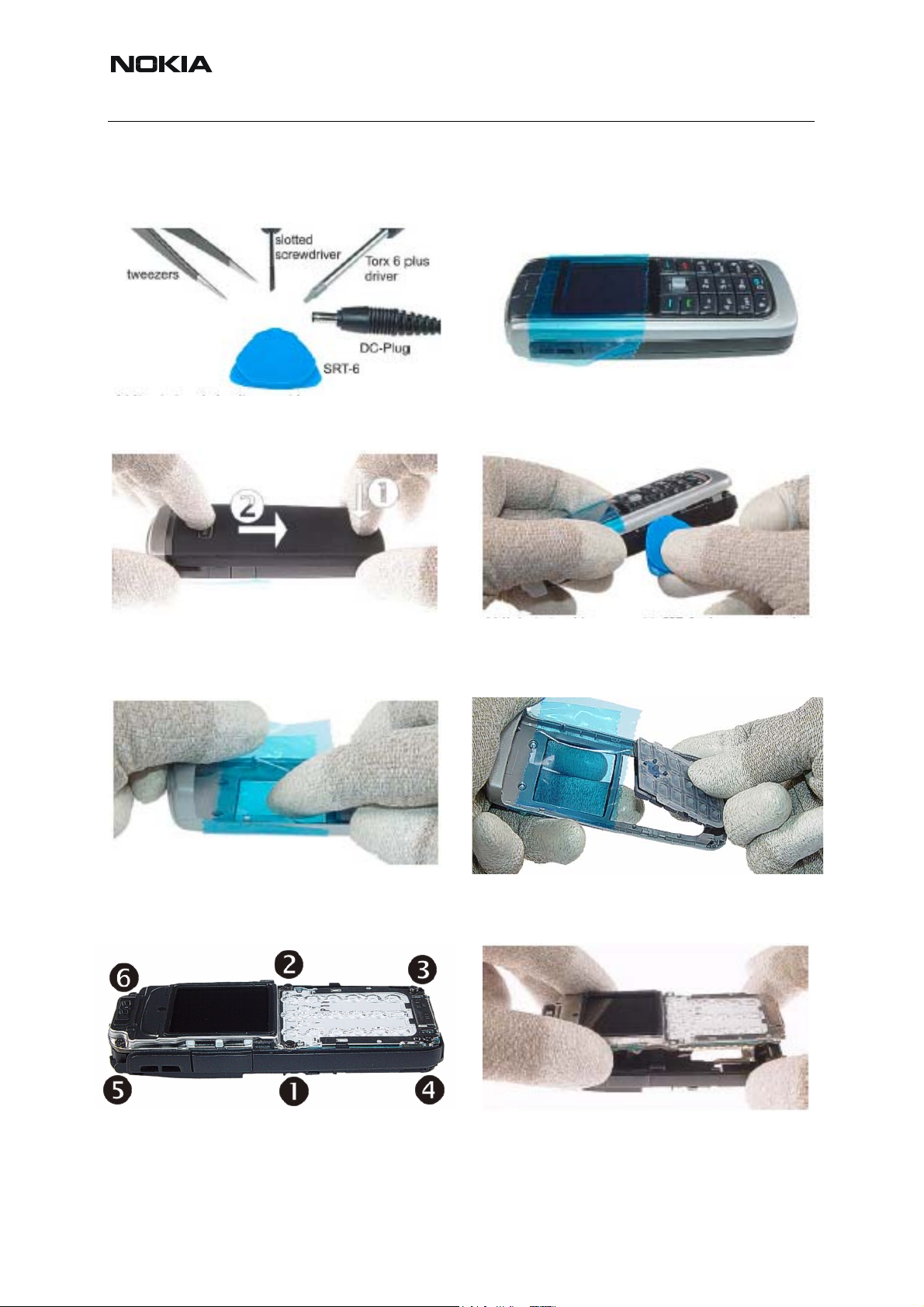
■ Detailed disassembly instructions
Needed tools for disassembly. Protect the window with a plastic film.
Remove the C-cover and protect the camera
window.
Also protect the inner side of the window with a
protective film.
Unlock the side snaps with SRT-6 when opening the A-cover.
Remove the keymat.
®
Unscrew the six Torx Plus
size 6 screws. For
assembly, the reverse order and a Torx Plus
Take the engine module from the B-cover.
®
driver with a torque of 28Ncm has to be used.
6 COMPANY CONFIDENTIAL Issue 1 04/2005
Copyright © 2005 Nokia. All Rights Reserved.
Page 7

RM-94
5 - Disassembly/Reassembly Instructions Nokia Customer Care
Carefully open the LCD connector. Do not
damage the LCD connector.
Lever out the LDC module from the UI shield. Protect the LCD module with a protective film.
Remove the UI shield assy with the LCD module.
Separate the light guide assy from the engine
module. Do not use the SRT -6 on the right side
to avoid damaging underneath components.
Remove the DC-jack with a DC-plug.
Issue 1 04/2005 COMPANY CONFIDENTIAL 7
Copyright © 2005 Nokia. All Rights Reserved.
Now, take away the light guide assy.
Remove the microphone with tweezers.
Page 8

RM-94
Nokia Customer Care 5 - Disassembly/Reassembly Instructions
Lever out the vibra motor.
Remove the volume key.
Remove the PDC key.
Remove the Bluetooth antenna with tweezers.
First unlock this side of the IHF lid with SRT-6.
Release the IHF speaker carefully with a slotted screwdriver. Always use a new speaker
adhesive when assembling.
8 COMPANY CONFIDENTIAL Issue 1 04/2005
Copyright © 2005 Nokia. All Rights Reserved.
Note that the IHF net stays in place during disassembly.
Page 9

RM-94
5 - Disassembly/Reassembly Instructions Nokia Customer Care
Note: It is not possible to disassemble the power actuator without damaging it. The power actuator is the same material as B-cover.
Note: If a new B-cover is used, a torque setting of 28Ncm and speed in the range of 400 - 600
rpm is required to cut the new thread.
Caution: The display connector is fragile. Movement of the display module/UI shield assembly
can damage the solder joints of connector on the display module or phone PWB. Ensure it is
held in place during unscrewing and screwing.
Reassembly
Reassembly should be in reverse order to disassembly unless otherwise stated.
Issue 1 04/2005 COMPANY CONFIDENTIAL 9
Copyright © 2005 Nokia. All Rights Reserved.
Page 10

RM-94
Nokia Customer Care 5 - Disassembly/Reassembly Instructions
Dome Sheet Placement
Since the dome sheet has to be removed before every soldering process a new dome sheet
needs to be placed between the PWM and light guide.
Note: In some regions the light guide assembly (which includes the ligh t guide, the meta l frame
and the domesheet) will be replaced as one part (this is the preferred procedure). The description below is needed, when the domesheet needs to be replaced separately, which is not the
preferred procedure.
■ Cleaning
The PWB needs to be cleaned and all remaining material from the old dome sheet needs to be
removed. In some regions there is the possibility to exchange the dome sheet separately (no t
together with the light guide assembly), then the light guide needs to be cleaned as well.
■ Placing the dome sheet to the light guide
The dome sheet is delivered on transparency foil. First step is to remove th e dome sheet from
the foil, where you need to ensure that the complete dome sheet is lifted and the protecting foil
on the other side of the dome sheet still sticks on the dome sheet. Please see picture below:
Protecting foil will
stick on dome sheet
All dome sheet parts
are lifted.
(Nothing sticks on
the bottom foil.)
10 COMPANY CONFIDENTIAL Issue 1 04/2005
Copyright © 2005 Nokia. All Rights Reserved.
Page 11

RM-94
5 - Disassembly/Reassembly Instructions Nokia Customer Care
Place the dome sheet onto the cleaned light guide and press them firmly together.
Take care, that the holes of the domesheet align exactly with the holes on the light-guide.
Issue 1 04/2005 COMPANY CONFIDENTIAL 11
Copyright © 2005 Nokia. All Rights Reserved.
Page 12

RM-94
Nokia Customer Care 5 - Disassembly/Reassembly Instructions
■ Placing the light guide assembly onto the PWB
In some regions there is the possibility to order the light guide assembly including the dome
sheet. In any case the protecting foil needs to be carefully removed from the dome sheet.
Then place the assembly to the PWB and press it firmly together.
Note: It is very important to press the light guide assembly and the PWB properly together at any
point. If some points are not pressed properly together dust and humidity will sneak between
PWB and dome sheet and will cause corrosion, which lead usability problems and to a defect
which might lead to a total loss of the phone.
Now you can be continue with the assembly procedure.
12 COMPANY CONFIDENTIAL Issue 1 04/2005
Copyright © 2005 Nokia. All Rights Reserved.
Page 13

RM-94
5 - Disassembly/Reassembly Instructions Nokia Customer Care
Component Replacement Hints
When exchanging components, all components must be placed properly. There is an extra
challenge when:
• Components are manually replaced
• Lead free process is applicable (which is the case for all RM-94 devices)
Therefore, the following replacement support and check possibilities have been implemented:
Figure 1: PWB overview
Issue 1 04/2005 COMPANY CONFIDENTIAL 13
Copyright © 2005 Nokia. All Rights Reserved.
Page 14

RM-94
Nokia Customer Care 5 - Disassembly/Reassembly Instructions
■ Power switch (S2419)
The power switch replacement has a direct influence to the phone usability and failure rates.
Improper placement can cause difficulties to switch the phone on / off or increase the switch’ s
sensitivity when dropping the phone (peeling of the switch or its pads). For proper p lacement,
the line behind the switch needs to fit properly (as shown in the picture below , it must be centric
and just visible) even after soldering to get proper functionality of the switch.
■ Helgo RF-chip (N7500)
There are also corner marks introduced in order to help checking the placement after rework.
The placement shall be done with proper equipment. The corner marks indicate proper placement after the soldering process. If the componen t is n ot place d pr operly th e re-work p rocess
must be repeated until the component fits properly.
14 COMPANY CONFIDENTIAL Issue 1 04/2005
Copyright © 2005 Nokia. All Rights Reserved.
Page 15

RM-94
5 - Disassembly/Reassembly Instructions Nokia Customer Care
■ Hardware accelerator (D1470)
There are also corner marks introduced in order to enable checking placement after rework
process.
■ UPP (D2800)
There are also corner marks introduced in order to help checking placemen t after rework process.
Issue 1 04/2005 COMPANY CONFIDENTIAL 15
Copyright © 2005 Nokia. All Rights Reserved.
Page 16

RM-94
Nokia Customer Care 5 - Disassembly/Reassembly Instructions
■ Flash (D3000)
There are some corner marks introduced.
■ SIM card reader (X2700)
There are some corner marks introduced.
16 COMPANY CONFIDENTIAL Issue 1 04/2005
Copyright © 2005 Nokia. All Rights Reserved.
Page 17

RM-94
5 - Disassembly/Reassembly Instructions Nokia Customer Care
■ System connector (X2002)
There are also some marks introduced (bars) in order to help placing the system connector and
checking placement after rework. The placement bars need to be visible (they can be partly
hidden by the connector), but the connector must equally hide them in order to be parallel to
the PWB. In addition, the connectors must meet their pads properly as well.
■ UEM (D2200)
There are also corner marks introduced in order to help checking placement after rework.
Issue 1 04/2005 COMPANY CONFIDENTIAL 17
Copyright © 2005 Nokia. All Rights Reserved.
Page 18

RM-94
Nokia Customer Care 5 - Disassembly/Reassembly Instructions
■ Battery connector (X2000)
There are also some corner marks introduced in order to support placement of the connector
and checking placement after rework.
18 COMPANY CONFIDENTIAL Issue 1 04/2005
Copyright © 2005 Nokia. All Rights Reserved.
Page 19

RM-94
5 - Disassembly/Reassembly Instructions Nokia Customer Care
■ Bluetooth transceiver
There are also some corner marks introduced in order to help checking placement after rework.
Issue 1 04/2005 COMPANY CONFIDENTIAL 19
Copyright © 2005 Nokia. All Rights Reserved.
Page 20

RM-94
l
A
Nokia Customer Care 5 - Disassembly/Reassembly Instructions
■ Label placement
Different countries require different labels. This guide explains where it is possible to place
these labels.
In the figure below, there are numbered shaded areas (1 - 5) where labels can be placed. On
the right hand side there are numbers and labels. The numbers refer to the place where the
label is allowed to be placed.
The T aiwan-specific label is met alized and it is very critical to place it properly , so that the phone
performance is not affected. For this reason it is allowed to place it on the named areas 2, 3
and 4, but not within the areas 1 and 5. The Chinese label, which is not metalized, has designated area 1.
5
2
11
Nokia Corporation
MADE BY NOKIA
168
1
1,2,3,4
5
.
1
4
5
2,3,4
1,2,3,4
Nokia Corporation
168
3
MADE BY NOKIA
China 12 x 30 not metal
Singapore 6x12 not meta
Malaysia 10 x 15 metal
(on top of Nokia label)
Taiwan 6 x 13 metal
T&T 6,2 x 25 not metal
Type Label
32,5 x 13 metal
20 COMPANY CONFIDENTIAL Issue 1 04/2005
Copyright © 2005 Nokia. All Rights Reserved.
 Loading...