

Page 1

Nokia Customer Care
6015/6015i/6016i/6019i (RH-55),
6012 (RM-20) Series Transceivers
Troubleshooting — Antenna
Issue 1 - Revision 002 09/2004 Company Confidential ©2004 Nokia Corporation
Page 2

6015/6015i/6016i/6019i (RH-55), 6012 (RM-20)
Troubleshooting — Antenna Nokia Customer Care
Contents Page
Introduction ..................................................................................................................................................... 3
Visual Quality Requirements ....................................................................................................................3
Whip Antenna............................................................................................................................................ 3
Internal Antenna ..........................................................................................................................................4
Failures and Corrective Measures.............................................................................................................. 5
Antenna Position into D-cover ............................................................................................................. 5
Internal Antenna ..........................................................................................................................................6
Damaged RF Feed or Ground Pins........................................................................................................ 7
Damaged IHF Speaker Pogo Pins.......................................................................................................... 7
Wrong Internal Antenna Installed ....................................................................................................... 7
Obstructed IHF Speaker, RF Feed, and Ground Pads....................................................................... 9
Broken or Missing Bottom Antenna Clip ........................................................................................ 10
Obstructed Whip Stopper.................................................................................................................... 10
Grounding of Display Frame ............................................................................................................... 11
Misinstalled Whip.................................................................................................................................. 12
Damaged Whips ..................................................................................................................................... 13
Detuning Circuit for Bottom Antenna Clip..................................................................................... 13
Testing the CDMA Antenna ...................................................................................................................... 14
Calibration Factors ................................................................................................................................ 14
Calibration Factor for PCS1900 Frequency .................................................................................... 14
Measurement Procedure for Cell800/PCS1900 Phones.............................................................. 14
Testing GPS Antenna (6015i/6016i/6019i) .......................................................................................... 15
Calibration Factor for GPS .................................................................................................................. 15
Measurement Procedure for GPS Antenna..................................................................................... 15
Page 2 ©2004 Nokia Corporation Company Confidential Issue 1 - Revision 002 09/2004
Page 3
6015/6015i/6016i/6019i (RH-55), 6012 (RM-20)
Nokia Customer Care Troubleshooting — Antenna
Introduction
The 6015/6015i/6016i/6019i, and 6012 incorporate a dual-band, internal/whip antenna
combination. This antenna arrangement is used for both AMPS/CELL and PCS frequency
bands. The whip is capacitively coupled to the internal antenna when extended. The
internal antenna assembly consists of a Planar Inverted-F Antenna (PIFA) used for the
cellular engine and an Inverted-F antenna (IFA) used for the GPS engine, which is placed
on the side of internal antenna body.
The GPS antenna is only active on models that support the GPS engine (i.e., 6015/6015i/
6016i/6019i).
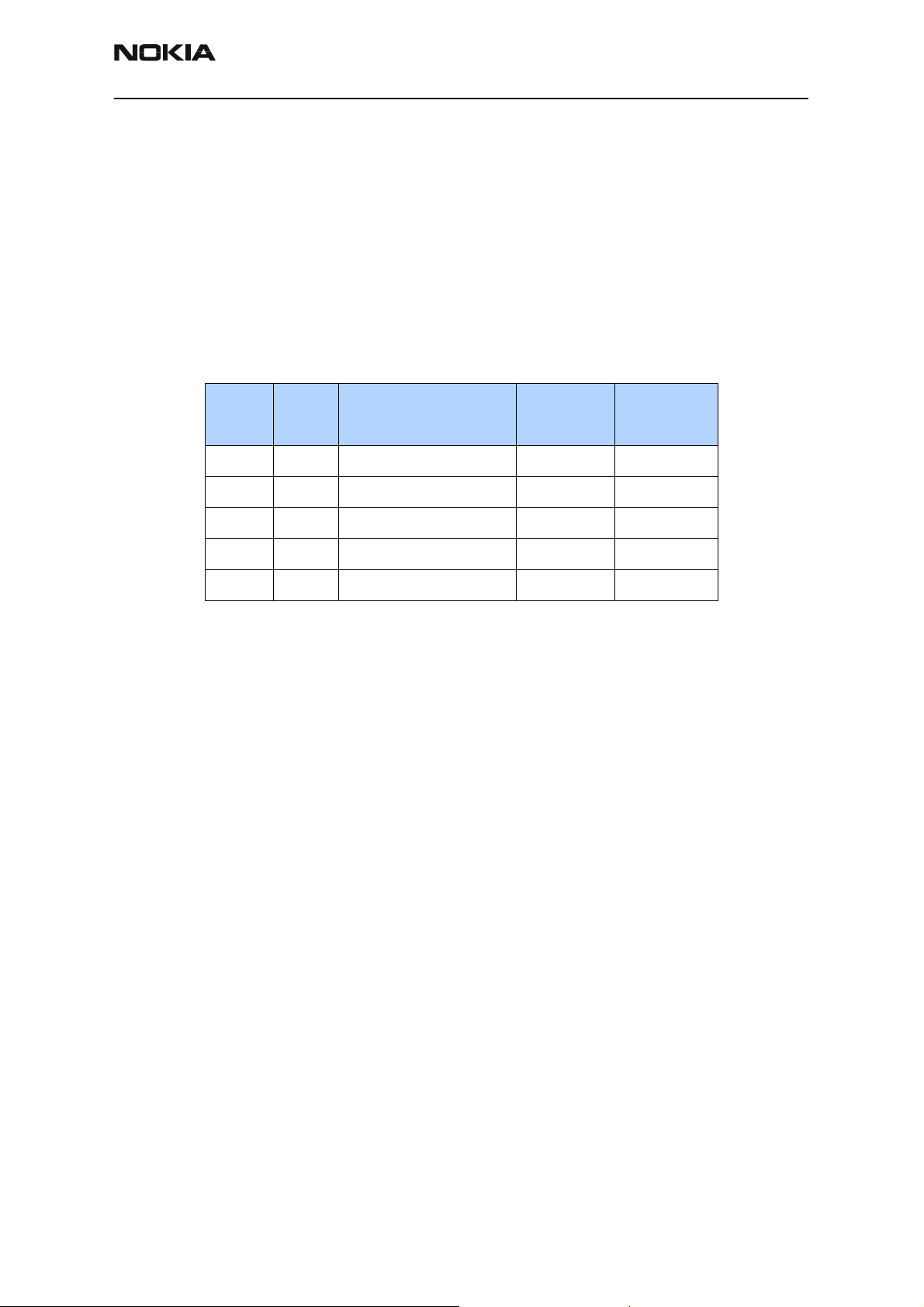
Model Type Technology
6012 RM-20 Analog and CDMA IS2000 800 No
6015 RH-55 Analog and CDMA IS2000 800/1900 No
6015i RH-55 Analog and CDMA IS2000 800/1900 Yes
6016i RH-55 Analog and CDMA IS2000 800/1900 Yes
6019i RH-55 Analog and CDMA IS2000 800/1900 Yes
Visual Quality Requirements
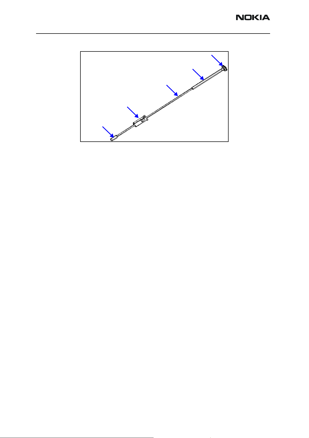
Whip Antenna
Check the following minimum visual quality requirements of the whip assembly:
• No physical cracks, bends, or mechanical defects
• No oil, corrosion, dirt, or particles
• Whip can be fully retracted and/or stowed without interference
• When fully retracted, antenna bottom stopper locks into antenna plug
Frequency
(MHz)
Active GPS
• Antenna wire and/or cap is not missing, cracked, or bent
• Color of antenna (cap, plug, wire and straw) is a very dark grey
• Wire straw is present with no visible defects
Issue 1 - Revision 002 09/2004 ©2004 Nokia Corporation Company Confidential Page 3
Page 4
6015/6015i/6016i/6019i (RH-55), 6012 (RM-20)
Troubleshooting — Antenna Nokia Customer Care
Cap
Telescopic tube
Wire
Plug
Bottom stopper
Figure 1: Whip assembly
Internal Antenna
Following are the minimum acceptable visual quality requirements of the internal
antenna assembly:
• Gloves must be used when handling antennas. Do not touch the antenna radiator
with bare hands.
• No visual cracks or mechanical defects.
• No oil, dirt, or particles are present on the parts.
• Radiator must be aligned with the plastic housing.
• GPS antenna contacts must be inside the plastic housing.
• Radiator must be flat with no warping.
• All pins must be at the same level.
Page 4 ©2004 Nokia Corporation Company Confidential Issue 1 - Revision 002 09/2004
Page 5
6015/6015i/6016i/6019i (RH-55), 6012 (RM-20)
Nokia Customer Care Troubleshooting — Antenna
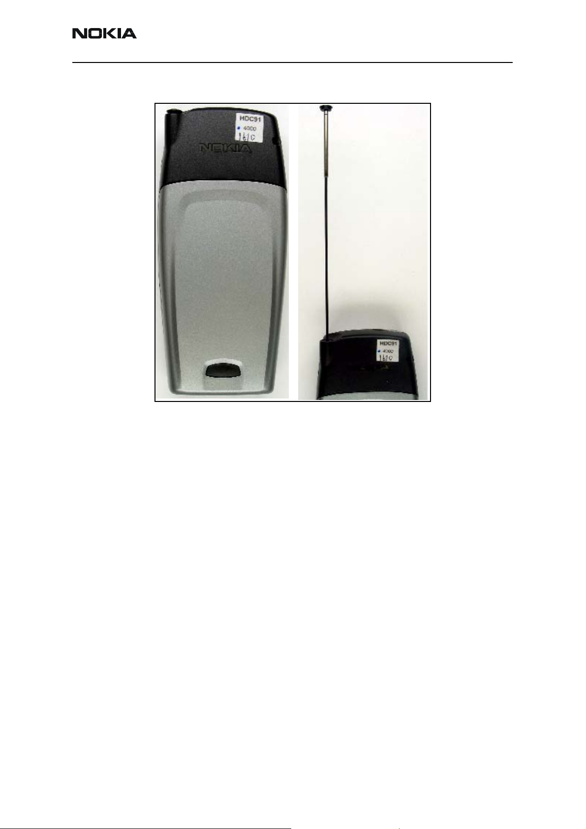
Failures and Corrective Measures
Figure 2: Back view with the whip retracted (left) and whip extended (right)
Note in Figure 2 that when the whip is properly installed, the cap clicks into the D-cover
when the whip is fully retracted.
Antenna Position into D-cover
The internal antenna and whip are assembled into the D-cover as shown in Figure 3. The
whip must be inserted prior to inserting the internal antenna.
If no internal antenna is installed, the antenna gain will be degraded by more than
25 dB.
Issue 1 - Revision 002 09/2004 ©2004 Nokia Corporation Company Confidential Page 5
Page 6

6015/6015i/6016i/6019i (RH-55), 6012 (RM-20)
Troubleshooting — Antenna Nokia Customer Care
Internal antenna
Whip antenna
Figure 3: D-cover assembly
• If the internal antenna is missing, install one. If the radiator looks obviously
damaged, then replace the internal antenna.
• If the whip is missing, then remove the internal antenna, install a whip, and
reinstall the internal antenna.
Internal Antenna
The internal antenna has a metal sheet (main antenna radiator) and a metal strip
(GPS antenna radiator) attached to a plastic carrier. An IHF mini speaker is integrated
inside the plastic.
Main antenna
radiator (PIFA)
GPS antenna
radiator (IFA)
Figure 4: Internal antenna
Note: The GPS antenna is only functional on the models supporting the GPS engine.
Page 6 ©2004 Nokia Corporation Company Confidential Issue 1 - Revision 002 09/2004
Page 7

6015/6015i/6016i/6019i (RH-55), 6012 (RM-20)
Nokia Customer Care Troubleshooting — Antenna
Damaged RF Feed or Ground Pins
The main antenna and the GPS antenna have pins (spring clips) that should properly
touch the PWB. If the RF feed pin of the main antenna does not touch the PWB, the
antenna gain will degrade by more than 25 dB and the GPS antenna will be detuned. If
the ground pin of the main antenna does not touch the PWB, the antenna gain may
degrade about 5 to 10 dB and the GPS antenna will be detuned.
If the RF feed pin of the GPS antenna does not touch the PWB, then the GPS antenna
gain will degrade by more than 20 dB. If the ground pin of the GPS antenna does not
touch the PWB, the GPS antenna gain may degrade more than 5 dB.
RF feed pin of
GPS antenna
Ground pin of
GPS antenna
Figure 5: Back view of the internal antenna
• If either the RF feed pin or ground pin are broken or bent such that either pin will
not touch the PWB, then replace the internal antenna.
• If the springs for the RF or ground pin appear damaged, then replace the internal
antenna.
Damaged IHF Speaker Pogo Pins
In Figure 5, the two pogo pins on the back of the internal antenna should properly touch
the PWB. If not, the PCS gain of the internal antenna could degrade about 2 dB and
there will be no audio from the speaker.
Ground pin of
main antenna
IHF mini speaker pogo pins
RF feed pin of
main antenna
Wrong Internal Antenna Installed
The internal antenna is mechanically similar to the internal antenna for the 2285, 2270,
2275 (RH-3 series) and the 2280 (RH-17) phones. There are three important differences
between the internal antennas:
• Only the internal antenna for the 6015/6015i/6016i/6019i, and 6012 phones
includes an IHF speaker.
• The slot pattern is very different among all three antennas.
• The radiators for the 2285, 2270, 2275 (RH-3 series) and the 2280 (RH-17)
phones are marked with an “F” and an “H” respectively.
Issue 1 - Revision 002 09/2004 ©2004 Nokia Corporation Company Confidential Page 7
Page 8

6015/6015i/6016i/6019i (RH-55), 6012 (RM-20)
Troubleshooting — Antenna Nokia Customer Care
Figure 6: Top view of the 6015/6015i/6016i/6019i, and 6012 internal antenna
Figure 7 shows the antennas for the 2285, 2270, 2275 and the 2280 phones. Ensure that
these antennas are not installed.
Figure 7: Top views of internal antenna for the 2285, 2270, 2275 (left)
and the 2280 (right) phones
Installing the 2285, 2270, 2275 or 2280 antenna in the 6015/6015i/6016i/6019i, and
6012 phones is not compliant with Nokia’s FCC submission because the 2285, 2270,
2275 (RH-3 series) antenna uses a single-band antenna (no PCS) and it does not have a
GPS antenna. The 2280 (RH-17) antenna is not tuned correctly for the 6015/6015i/
6016i/6019i, and 6012 mechanics.
• If the wrong antenna is installed, install the correct one.
• If the slot in the radiator has a significantly different shape, then install the
correct internal antenna. Be aware that the shape of the slot can vary slightly.
The length of the horizontal slot and the opening of the vertical slot can vary by
few millimeters because the antennas are tuned for each batch of plastic frames.
• If there is any other obvious damage to the radiator (dents, corrosion), replace
the antenna.
• If the pin gets stuck or has excessive friction in the plastic tube/guiding feature,
then the spring will not work properly, and you should replace the antenna.
Page 8 ©2004 Nokia Corporation Company Confidential Issue 1 - Revision 002 09/2004
Page 9

6015/6015i/6016i/6019i (RH-55), 6012 (RM-20)
Nokia Customer Care Troubleshooting — Antenna
Obstructed IHF Speaker, RF Feed, and Ground Pads
RF feed pad for
GPS antenna
IHF speaker
pads
Ground pad
for main
antenna
RF feed pad
for main
antenna
Figure 8: PWB layout of IHF speaker, RF feed, and ground pads, as well as the bottom antenna clip
Ground pad for
GPS antenna
Bottom antenna clip
If any of the RF feed or ground pins are obstructed, removed, or covered, then the RF pin
will not touch the PWB and the antenna performance will degrade. If any of the IHF
speaker pads are obstructed, removed, or covered, the speaker’s pogo pin will not touch
the PWB and the antenna performance at PCS could degrade. See the "Damaged IHF
Speaker Pogo Pins" section for antenna performance degradation if any pogo pin does
not touch the PWB.
• If corrosion is present or the pad is missing, then you should replace the PWB and
the phone.
• If a pad is obstructed or covered, then clear and/or clean the pad.
Issue 1 - Revision 002 09/2004 ©2004 Nokia Corporation Company Confidential Page 9
Page 10

6015/6015i/6016i/6019i (RH-55), 6012 (RM-20)
Troubleshooting — Antenna Nokia Customer Care
Broken or Missing Bottom Antenna Clip
If the bottom antenna clip does not contact the whip stopper when the whip is fully
retracted, the internal antenna gain will degrade by about 4-5dB at Cell band and
3-10dB at PCS band.
• If the antenna clip is installed backwards, is damaged, or is missing, then install a
new bottom antenna clip in the correct position.
Obstructed Whip Stopper
If the whip stopper does not properly contact the bottom antenna clip, then the internal
antenna gain will degrade by about 4-5dB at Cell band and 3-10dB at PCS band when
the whip is retracted.
Figure 9: Bottom antenna clip
Whip stopper contacts the
bottom antenna clip
Figure 10: Whip stopper as shown when the whip is fully retracted
Page 10 ©2004 Nokia Corporation Company Confidential Issue 1 - Revision 002 09/2004
Page 11

6015/6015i/6016i/6019i (RH-55), 6012 (RM-20)
Nokia Customer Care Troubleshooting — Antenna
• If the whip stopper is corroded or blocked by the whip straw, replace the whip
assembly.
• If the whip stopper is obstructed or dirty, remove the obstruction and/or dirt.
Grounding of Display Frame
Note that the display frame is grounded to the PWB through the two ground clips. The
grounding of the display frame impacts the radiation performance of the phone.
Display frame
ground clips
Figure 11: Back view of display assembly
• If the clips are not touching the PWB, are corroded, or are obstructed, replace the
display frame.
The following figures show the contact between the display frame ground clips and the
PWB in greater detail.
Figure 12: Contacts of display frame clips with side plating of the PWB
Issue 1 - Revision 002 09/2004 ©2004 Nokia Corporation Company Confidential Page 11
Page 12

6015/6015i/6016i/6019i (RH-55), 6012 (RM-20)
Troubleshooting — Antenna Nokia Customer Care
Figure 13: View of display ground clip in assembled phone with A-cover removed
Misinstalled Whip
The whip is locked into the D-cover when the internal antenna frame is installed. There is
a feature in the plastic frame of the internal antenna that interlocks with the locking
feature of the whip. The whip plug has the locking feature, and also has a key that is
designed to make it difficult to install the whip plug with the wrong rotation. If the whip
plug is installed with the wrong rotation, then the whip will not be visible as seen
through the locking feature
Locking feature
Figure 14: Locking feature for whip
• If the whip cannot be removed, replace the D-cover assembly. Otherwise, replace
the whip antenna.
Page 12 ©2004 Nokia Corporation Company Confidential Issue 1 - Revision 002 09/2004
Page 13

6015/6015i/6016i/6019i (RH-55), 6012 (RM-20)
Nokia Customer Care Troubleshooting — Antenna
Damaged Whips
Figure 15 shows what the whip should look like when it is retracted and extended. If the
whip is damaged, replace it.
Figure 15: Whip stand-alone in retracted and extended positions
Detuning Circuit for Bottom Antenna Clip
Figure 9 on page 10 shows the bottom antenna clip. The detuning circuit is right next to
the bottom antenna clip. If the detuning circuit is not installed properly, then the
internal antenna gain will degrade by about 4-5dB at Cell band and 3-10dB at PCS band.
The GPS antenna gain will be degraded by more than 2 dB with the whip in the retracted
position. The detuning circuit consists of a 1.2nH coil inductor and an 8.2 pF capacitor.
• If either the inductor or capacitor is missing, install one.
Issue 1 - Revision 002 09/2004 ©2004 Nokia Corporation Company Confidential Page 13
Page 14

6015/6015i/6016i/6019i (RH-55), 6012 (RM-20)
Troubleshooting — Antenna Nokia Customer Care
Testing the CDMA Antenna
Calibration Factors
Define the AMS RF coupler CPL-8 calibration numbers using the test adapter MJF-28.
Obtain the calibration numbers by utilizing a phone with known RF and antenna
performance. Each test adapter should only require a single calibration on PCS1900 and
GPS bands at used test frequencies. Additional calibrations should only be needed if the
test adapter is substantially modified (reassembled, changed parts, dropped, etc.).
Calibration Factor for PCS1900 Frequency
Use a call box to turn on the transmitter of the phone with a known output power and
antenna performance at the maximum output power (all bits up). Measure the
transmitted power on the RF connector and through a coupler at CDMA PCS channel
1175. Use the difference between the transmitted and received powers as the calibration
number (path loss on Cell band including coupler, cable, and attenuator path losses) for
the coupler on Cell band.
The nominal value for power measured at the RF connector is 23 dBm. The coupler path
loss is normally ~17…18 dB at the PCS band. If a 10 dB attenuator and a cable with
~1 dB loss is used, the total path loss is 28 to 29 dB and the measured power should be
from -5 to -6 dBm [23 dBm - (28…29 dB)]. However, path loss has to be measured
separately for every coupler because path losses vary depending on the setup, cables, and
attenuator.
Measurement Procedure for Cell800/PCS1900 Phones
1. Place the phone with the display up in the test adapter (MJF-28) with its whip
retracted.
2. Turn on the phone's transmitter at the PCS band on CDMA mode channel 1175 at
maximum output power (nominal 23 dBm at RF connector).
3. Measure the RF power with a CPL-8 coupler. This represents the internal antenna
to RF coupler measurement.
4. Turn the phone's transmitter off.
The CDMA antenna test fails if the measured power is outside the test limits.
Table 1: CDMA Measurement Test Limits
Min Measured Power + Coupler,
Cable and Attenuator Path Loss
20,0 dBm 23 dBm 26,0 dBm
Page 14 ©2004 Nokia Corporation Company Confidential Issue 1 - Revision 002 09/2004
Nominal
Max Measured Power + Coupler,
Cable and Attenuator Path Loss
Page 15

6015/6015i/6016i/6019i (RH-55), 6012 (RM-20)
Nokia Customer Care Troubleshooting — Antenna
Testing GPS Antenna (6015i/6016i/6019i)
Calibration Factor for GPS
In GPS test mode 3, the GPS receiver is fed with a CW signal. The GPS receiver should
report C/No ratio of 35 dBHz with a -110 dBm signal level on the RF connector
(-110 dBm + cable loss) at signal generator output. The reported C/No figure is recorded
with the signal fed to the RF connector. The C/No value is read with a coupler engaged.
Increase the GPS signal level until the same C/No value is recorded. Use the difference
between the CW signal levels at the generator as the calibration number (path loss on
GPS band including coupler, cable, and attenuator losses).
The nominal coupler path loss at GPS band is 14 to 17 dB. If you use a 10 dB attenuator
and cable with 1 dB loss, the total path loss is 25 to 28 dB. The signal level at generator
output must be -85 to -82 dBm [-110 dBm -(-25 dB to -28 dB)]. However, the path loss
has to be measured separately for every coupler because the path losses vary depending
on the setup, cables, and attenuator.
Measurement Procedure for GPS Antenna
1. Place the phone in the test adapter (MJF-28) with the display up and the whip
retracted.
2. Turn on the CW signal generator [with power -110 dBm + coupler, cable, and
attenuator path loss at GPS band] fed to the RF coupler.
3. Read the reported C/No figure with the test mode 3 three to four times to see if
it is stable.
The GPS antenna test fails if the C/No value is outside the test limits.
Table 2: GPS Antenna Measurement Test Limits
Min Nominal Max
31,0 dBHz 35,0 dBHz 38,5 dBHz
Issue 1 - Revision 002 09/2004 ©2004 Nokia Corporation Company Confidential Page 15
Page 16

6015/6015i/6016i/6019i (RH-55), 6012 (RM-20)
Troubleshooting — Antenna Nokia Customer Care
This page intentionally left blank.
Page 16 ©2004 Nokia Corporation Company Confidential Issue 1 - Revision 002 09/2004
 Loading...