

Page 1

PAMS Technical Documentation
NSC/W–1/3 Series Transceivers
Disassembly &
Troubleshooting
Instructions
Original 09/98
Page 2

NSC/W–1/3
PAMS
Disassembly & Troubleshooting Instructions
AMENDMENT RECORD SHEET
Amendment
Number
Date Inserted By Comments
05/98 Original
Issue2 09/98
O Juntunen
Technical Documentation
P.4 5. screw added
p.5 IR removed
Troubleshooting revised
IC data added
Page 2
Original 09/98
Page 3

PAMS
NSC/W–1/3
Technical Documentation
Disassembly & Troubleshooting Instructions
CONTENTS
Disassembly 4. . . . . . . . . . . . . . . . . . . . . . . . . . . . . . . . . . . . . . . . .
Introduction 6. . . . . . . . . . . . . . . . . . . . . . . . . . . . . . . . . . . . . . . . . .
Abbreviations in RF–fault finding charts 6. . . . . . . . . . . . . . .
Interface signals between RF and BB/DSP 7. . . . . . . . . . . .
Trouble Shooting 11. . . . . . . . . . . . . . . . . . . . . . . . . . . . . . . . . . . . .
Phone is totally dead 11. . . . . . . . . . . . . . . . . . . . . . . . . . . . . . . . . .
The phone doesn’t register to the network 12. . . . . . . . . . . . . . .
Flash programming doesn’t work 13. . . . . . . . . . . . . . . . . . . . . . .
Power doesn’t stay on, or phone is jammed 15. . . . . . . . . . . . . .
Display Information: Contact Service 17. . . . . . . . . . . . . . . . . . . .
Audio failure 18. . . . . . . . . . . . . . . . . . . . . . . . . . . . . . . . . . . . . . . . .
Charging failure 20. . . . . . . . . . . . . . . . . . . . . . . . . . . . . . . . . . . . . .
Receiver Fault AMPS 21. . . . . . . . . . . . . . . . . . . . . . . . . . . . . . . . .
General Instructions 21. . . . . . . . . . . . . . . . . . . . . . . . . . . . . . . .
Path of the received signal 21. . . . . . . . . . . . . . . . . . . . . . . . . .
Receiver Fault AMPS 22. . . . . . . . . . . . . . . . . . . . . . . . . . . . . . . . .
Receiver Fault TDMA800 24. . . . . . . . . . . . . . . . . . . . . . . . . . .
Receiver Fault TDMA1900 (only for dualbander) 26. . . . . . .
Transmitter Fault – General 28. . . . . . . . . . . . . . . . . . . . . . . . . . . .
Path of the transmitted signal 28. . . . . . . . . . . . . . . . . . . . . . . .
Transmitter Fault AMPS 29. . . . . . . . . . . . . . . . . . . . . . . . . . . . .
Transmitter Fault TDMA800 31. . . . . . . . . . . . . . . . . . . . . . . . .
Transmitter Fault TDMA1900 32. . . . . . . . . . . . . . . . . . . . . . . .
Power Control Loop 34. . . . . . . . . . . . . . . . . . . . . . . . . . . . . . . .
Synthesizers 35. . . . . . . . . . . . . . . . . . . . . . . . . . . . . . . . . . . . . . . . .
19.44 MHz reference oscillator 35. . . . . . . . . . . . . . . . . . . . . .
58.32 MHz 3–multiplier 35. . . . . . . . . . . . . . . . . . . . . . . . . . . . .
19.44 MHz oscillator and 3–multiplier troubleshooting 36. .
VHF VCO 36. . . . . . . . . . . . . . . . . . . . . . . . . . . . . . . . . . . . . . . . . . .
VHF VCO troubleshooting 37. . . . . . . . . . . . . . . . . . . . . . . . . . .
AMPS & TDMA UHF SYNTHESIZER 38. . . . . . . . . . . . . . . . .
1GHz UHFsynthesizer troubleshooting 38. . . . . . . . . . . . . . . .
TDMA1900 UHF Synthesizer 2 GHz (DUALBANDER) 39. .
2 GHz UHF synthesizer troubleshooting 39. . . . . . . . . . . . . . .
About RF ASICs and MMIC PA 40. . . . . . . . . . . . . . . . . . . . . .
General information 40. . . . . . . . . . . . . . . . . . . . . . . . . . . . . . . .
PLUSSA ASIC 40. . . . . . . . . . . . . . . . . . . . . . . . . . . . . . . . . . . . .
Receiver front ends 42. . . . . . . . . . . . . . . . . . . . . . . . . . . . . . . . .
MMIC Power Amplifiers 42. . . . . . . . . . . . . . . . . . . . . . . . . . . . .
PENTA regulator 43. . . . . . . . . . . . . . . . . . . . . . . . . . . . . . . . . . .
TDMA1900 UPCONVERTER 44. . . . . . . . . . . . . . . . . . . . . . . .
TDMA1900 PLL 44. . . . . . . . . . . . . . . . . . . . . . . . . . . . . . . . . . . .
Page No
Original 09/98
Page 3
Page 4

NSC/W–1/3
PAMS
Disassembly & Troubleshooting Instructions
Disassembly
NOTE: Do not attempt antenna removal white the covers are on. The antenna can be removed only when the phone covers are off
Remove battery
Technical Documentation
Remove dust cap by finger nail
Remove back cover
screws (4pcs phase1,
5 pcs phase 2).
NOTE!
When assembling the
B cover screws, use
17 Ncm torque.
Turn around.
Remove UI module
screws (2 pcs)
Carefully remove A–cover, keymat, powerkeymat
and speaker will follow.
Note snap fixings !
Page 4
Original 09/98
Page 5

PAMS
NSC/W–1/3
Technical Documentation
Remove UI–module
and frame
Disassembly & Troubleshooting Instructions
Remove engine module
screw (1 pc). Phase 1
version does not have
the screw, phase 2 has.
To remove antenna :
push in snap at antenna
base with screwdriver tip
while pushing antenna
out of B cover.
Remove engine
module
Original 09/98
Remove
microphone
Page 5
Page 6

NSC/W–1/3
PAMS
Disassembly & Troubleshooting Instructions
Introduction
RF–measurements must be done using a spectrum analyzer and an high–
frequency probe. (Local and reference frequencies and RF power levels in
the intermediate stages of the chain) Oscilloscope is used to measure DC–
voltages and low frequency signals. Multimeter is also a useful measurement equipment in fault finding.
The external RF connector must be used when reasonable to improve the
reliability of the measurement results.
The RF–section is mainly built around the PLUSSA IC (N750). The RF block
has separate external filters, UHF synthesizer , Power Amplifier , TX Driver,
frontend and upconverter circuit for both frequency bands. In the
TDMA1900 mode the external regulator is used to provide supply voltage for
RF parts.
Before changing single ASICs or components, please check the following :
1. The soldering and connections of pins of the ASICS are OK
2. Supply voltages and control signals are OK
3.Signals of the synthesizers are coming to ASICS. This to prevent the unnecessary changing of the ASICS.
Technical Documentation
NOTE! Grounding of the P A–IC is directly underneath so it is hard to check.
The P A–module is static discharge sensitive! So ESD protection must be
used when dealing with P A–IC (ground straps and ESD soldering tools). The
P A is also a moisture sensitive components and it is important to follow additional information about handling the component.
There are still lots of discrete components (resistors, inductors and capacitors) troubleshooting of which comprises just checking that the component
is soldered or it is not missing from PCB.
Abbreviations in RF–fault finding charts
TP Test Point
BB Baseband
f: Frequency of signal (measured with spectrum analyzer)
LO Local Oscillator
P: Power of signal in desibels (dB)
(measured with spectrum analyzer)
PA Power Amplifier
PCB Printed Circuit Board
PLL Phase Locked Loop
RF Radio Frequency
RX Receiver
T: Time between pulses
TX Transmitter
UHF Ultra High Frequency
V: Voltage of signal (measured with oscilloscope)
VCO Voltage controlled oscillator
VHF Very High Frequency
AF: Audio Frequency
Page 6
Original 09/98
Page 7

PAMS
ÁÁÁ
ÁÁÁ
Á
Á
Á
Á
Á
Á
Á
Á
Á
Á
Á
Á
Á
Á
Á
ÁÁÁ
Á
Á
Á
Á
Á
Á
Á
Á
Á
ÁÁÁ
Á
Á
Á
Á
Á
Á
Á
Á
Á
Á
Á
Á
Á
Á
Á
Á
Á
Á
Á
Á
Á
Á
Á
Á
Á
Á
Á
Á
Á
Á
Á
Á
Á
Á
Á
Á
Á
Á
Á
Á
Á
Á
Á
Á
Á
Á
Á
Á
Á
Á
Á
Á
Á
Á
Á
Á
Á
Á
Á
Á
Á
Á
Á
Á
Á
Á
Á
Á
Á
Á
Á
Á
Á
Á
Á
Á
Á
Á
Á
Á
Á
Á
Á
Á
Á
Á
Á
Á
Á
Á
Á
Á
Á
Á
Á
Á
Á
Á
Á
Á
Á
Á
Á
Á
Á
Á
Á
Á
Á
Á
Á
Á
Á
Á
Á
Á
Á
Á
Á
Á
Á
Á
Á
Á
Á
Á
Á
Á
Á
Á
Á
Á
Á
Á
Á
Á
Á
Á
Á
Á
Á
Á
Á
Á
Á
Á
Á
Á
Á
Á
Á
Á
Á
Á
Á
Á
Á
Á
Á
Á
Á
Á
Á
Á
Á
Á
Á
Á
Á
Á
Á
Á
Á
Á
Á
Á
Á
Á
Á
Á
Á
Á
Á
Á
Á
Á
Á
Á
NSC/W–1/3
Technical Documentation
Disassembly & Troubleshooting Instructions
Interface signals between RF and BB/DSP
Signal
name
VBAT
ÁÁÁ
NOTE!
ÁÁÁ
Not char-
ÁÁÁ
ger
VREF
ÁÁÁ
ÁÁÁ
RFTEMP
ÁÁÁ
ÁÁÁ
ÁÁÁ
AFC
ÁÁÁ
AGC1
AGC2
ÁÁÁ
ÁÁÁ
ÁÁÁ
ÁÁÁ
BAND
ÁÁÁ
MODE
ÁÁÁ
IF2AP/
ÁÁÁ
IF2AN
ÁÁÁ
IF2DP /
ÁÁÁ
IF2DN
ÁÁÁ
SENA1
ÁÁÁ
From
Battery
ÁÁ
ÁÁ
ÁÁ
CCONT
ÁÁ
ÁÁ
RF
ÁÁ
ÁÁ
ÁÁ
COBBA_D
ÁÁ
Cobba_D
MAD
ÁÁ
ÁÁ
ÁÁ
ÁÁ
COBBA_D
ÁÁ
MAD
ÁÁ
PLUSSA
ÁÁ
ÁÁ
PLUSSA
ÁÁ
ÁÁ
MAD
ÁÁ
To
RF
ÁÁÁ
ÁÁÁ
ÁÁÁ
PLUSSA
ÁÁÁ
ÁÁÁ
CCONT
ÁÁÁ
ÁÁÁ
ÁÁÁ
VCTCXO
c
ÁÁÁ
PLUSSA
RX LNA
ÁÁÁ
ÁÁÁ
ÁÁÁ
ÁÁÁ
VHF VCO
ÁÁÁ
1Ghz PA
ÁÁÁ
COB-
ÁÁÁ
BA_D
ÁÁÁ
COB-
ÁÁÁ
BA_D
ÁÁÁ
PLUSSA
ÁÁÁ
Parameter
Voltage
БББББ
БББББ
БББББ
Voltage
БББББ
БББББ
Voltage
БББББ
БББББ
БББББ
Voltage
БББББ
Voltage
Voltage
БББББ
БББББ
БББББ
БББББ
Voltage
БББББ
Voltage
БББББ
Voltage/Frequency
БББББ
БББББ
Voltage/Frequency
БББББ
БББББ
Logic high ”1”
БББББ
Logic low ”0”
Minimum
3.1
ÁÁ
ÁÁ
ÁÁ
1.478
ÁÁ
ÁÁ
0
ÁÁ
HOT
ÁÁ
ÁÁ
0.05
ÁÁ
0.5
0
ÁÁ
ÁÁ
ÁÁ
ÁÁ
0
ÁÁ
0
ÁÁ
ÁÁ
ÁÁ
ÁÁ
ÁÁ
2.0
ÁÁ
0
Typi-
cal
3.6
1.500
1.4
ROO
M
TEMP
1.1
Á
Á
Á
Á
Á
Á
Á
Á
Á
Maxi-
mum
5.3
ÁÁ
ÁÁ
5.0
ÁÁ
1.523
ÁÁ
ÁÁ
2.7
ÁÁ
COLD
ÁÁ
ÁÁ
2.25
ÁÁ
1.4
2.85
Á
Á
Á
Á
ÁÁ
ÁÁ
ÁÁ
ÁÁ
2.85
ÁÁÁÁ
2.85
ÁÁÁÁ
0.6 /
Á
450
Á
170 /
Á
450
Á
ÁÁÁÁÁÁ
ÁÁ
ÁÁ
1400
ÁÁ
ÁÁ
0.8
Unit
V
Á
Á
Á
V
Á
Á
V
Á
Á
Á
V
Á
V
V
Á
Á
Á
Á
V
Á
V
Á
Vpp /
Á
kHz
Á
mVpp
Á
/ kHz
Á
V
V
Function
Supply volt-
ÁÁÁÁ
age for RF
ÁÁÁÁ
ÁÁÁÁ
Reference
ÁÁÁÁ
voltage for
PLUSSA
ÁÁÁÁ
RF temperature sensor
ÁÁÁÁ
47k NTC to
ÁÁÁÁ
GND
ÁÁÁÁ
Automatic
frequency
ÁÁÁÁ
control
LNA Gain
ÁÁÁÁ
switch
ÁÁÁÁ
“1” min 2.0 V
ÁÁÁÁ
“0” max 0.7
ÁÁÁÁ
V
“0” 2 Ghz
ÁÁÁÁ
“1” 1 GHz
“0” AMPS
ÁÁÁÁ
“1” TDMA
Differential
ÁÁÁÁ
limiter output
to DEMO de-
ÁÁÁÁ
tector
Differential
ÁÁÁÁ
IF2–signal to
RX A/D–con-
ÁÁÁÁ
verter
1 Ghz PLL
ÁÁÁÁ
enable
SDATA
ÁÁÁ
SCLK
ÁÁÁ
RFC
ÁÁÁ
ÁÁÁ
Original 09/98
MAD2
ÁÁ
MAD2
ÁÁ
VCTCXO
ÁÁ
ÁÁ
PLUSSA
ÁÁÁ
PLUSSA
ÁÁÁ
COB-
ÁÁÁ
BA_D
ÁÁÁ
Logic high ”1”
БББББ
Logic low ”0”
Logic high ”1”
БББББ
Logic low ”0”
Voltage/Frequency
БББББ
БББББ
2.0
ÁÁ
0
2.0
ÁÁ
0
0.2
ÁÁ
ÁÁ
ÁÁÁÁÁÁ
0.8
ÁÁÁÁÁÁ
0.8
0.4 /
19.44
Á
Á
1.0
ÁÁ
ÁÁ
V
V
V
V
Vpp /
Á
MHz
Á
Synthesizer
ÁÁÁÁ
data
Synthesizer
ÁÁÁÁ
clock
Clock signal
ÁÁÁÁ
for the logic
circuits
ÁÁÁÁ
Page 7
Page 8

NSC/W–1/3
Á
Á
Á
Á
Á
Á
Á
Á
Á
Á
Á
Á
Á
Á
Á
Á
Á
Á
Á
Á
Á
Á
Á
Á
Á
Á
Á
Á
Á
Á
Á
Á
Á
Á
Á
Á
Á
Á
Á
Á
Á
Á
Á
Á
Á
Á
Á
Á
Á
Á
Á
Á
Á
Á
Á
Á
Á
Á
Á
Á
Á
Á
Á
Á
Á
Á
Á
Á
Á
Á
Á
Á
Á
Á
Á
Á
Á
Á
Á
Á
Á
Á
Á
Á
Á
Á
Á
Á
Á
Á
Á
Á
Á
Á
Á
Á
Á
Á
Á
Á
Á
Á
Á
Á
Á
Á
Á
Á
Á
Á
Á
Á
Á
Á
Á
Á
Á
Á
Á
Á
Á
Á
Á
Á
Á
Á
Á
Á
Á
Á
Á
Á
Á
Á
Á
Á
Á
Á
Á
Á
Á
Á
Á
Á
Á
Á
Á
Á
Á
Á
Á
Á
Á
Á
Á
Á
Á
Á
Á
Á
Á
Á
Á
Á
Á
Á
Á
Á
Á
Á
Á
Á
Á
Á
Á
Á
Á
Á
Á
Á
Á
Á
Á
Á
Á
Á
Á
Á
Á
Á
Á
Á
Á
Á
Á
Á
Á
Á
Á
Á
Á
Á
Á
Á
Á
Á
Á
Á
Á
Á
Á
Á
Á
Á
Á
Á
Á
Á
Á
Á
Á
Á
Á
Á
Á
Á
Á
Á
Á
Á
Á
Á
Á
Á
Á
Á
Á
Á
Á
Á
Á
Á
Á
Á
Á
Á
Á
Á
Á
Á
Á
Á
Á
PAMS
Disassembly & Troubleshooting Instructions
RFCEN
ÁÁÁ
ÁÁÁ
RSSI
ÁÁÁ
ÁÁÁ
TXIP/
TXIN
ÁÁÁ
ÁÁÁ
ÁÁÁ
ÁÁÁÁÁÁÁÁÁÁÁБББББ
TXQP/
ÁÁÁ
TXQN
ÁÁÁ
ÁÁÁ
ÁÁÁ
TXP1
ÁÁÁ
ÁÁÁ
ÁÁÁ
TXC
ÁÁÁ
ÁÁÁ
ÁÁÁ
MAD
ÁÁ
ÁÁ
PLUSSA
ÁÁ
ÁÁ
COBBA
ÁÁ
ÁÁ
ÁÁ
COBBA
ÁÁ
ÁÁ
ÁÁ
ÁÁ
MAD
ÁÁ
ÁÁ
ÁÁ
COBBA
ÁÁ
ÁÁ
ÁÁ
CCONT /
ÁÁÁ
PENTA
regulator
ÁÁÁ
CCONT
ÁÁÁ
ÁÁÁ
PLUSSA
ÁÁÁ
ÁÁÁ
ÁÁÁ
PLUSSA
ÁÁÁ
ÁÁÁ
ÁÁÁ
ÁÁÁ
CCont
ÁÁÁ
ÁÁÁ
ÁÁÁ
PLUSSA
ÁÁÁ
ÁÁÁ
ÁÁÁ
Voltage
БББББ
БББББ
Output level
БББББ
БББББ
Differential voltage
swing (static)
БББББ
БББББ
БББББ
Output level on
each output
Same as TXIP/
БББББ
TXIN
БББББ
БББББ
БББББ
Logic high ”1”
БББББ
БББББ
БББББ
Logic low ”0”
Number of bits
БББББ
БББББ
БББББ
0
ÁÁ
ÁÁ
0.1
ÁÁ
ÁÁ
1.022
ÁÁ
ÁÁ
ÁÁ
0.760
ÁÁ
ÁÁ
ÁÁ
ÁÁ
ÁÁ
2.0
ÁÁ
ÁÁ
ÁÁ
10
ÁÁ
ÁÁ
ÁÁ
Technical Documentation
1.1
0.8
Á
Á
Á
Á
Á
Á
Á
Á
Á
Á
Á
Á
Á
Á
Á
Á
Á
Á
2.85
ÁÁ
ÁÁ
1.5
ÁÁ
ÁÁ
1.18
ÁÁ
ÁÁ
ÁÁ
0.84
ÁÁ
ÁÁ
ÁÁ
ÁÁ
ÁÁ
ÁÁ
ÁÁ
ÁÁ
0.5
ÁÁ
ÁÁ
ÁÁ
V
V
Vpp
V
V
V
bits
Á
Á
Á
Á
Á
Á
Á
Á
Á
Á
Á
Á
Á
Á
Á
Á
Á
Á
“1” min 2.0 V
ÁÁÁÁ
“0” max 0.4
ÁÁÁÁ
V
Analog mode
ÁÁÁÁ
field sternght
indicator
ÁÁÁÁ
Differential
in–phase TX
ÁÁÁÁ
baseband
ÁÁÁÁ
signal for the
RF modula-
ÁÁÁÁ
tor
ÁÁÁÁ
Differential
ÁÁÁÁ
quadrature
phase TX
ÁÁÁÁ
baseband
ÁÁÁÁ
signal for the
RF modula-
ÁÁÁÁ
tor
1 Ghz Trans-
ÁÁÁÁ
mitter power
ÁÁÁÁ
control enable
ÁÁÁÁ
VR7 ON/
OFF
Transmitter
ÁÁÁÁ
power con-
ÁÁÁÁ
trol (ramps &
power levels)
ÁÁÁÁ
ÁÁÁÁÁÁÁÁÁÁÁБББББ
Output voltage
swing
Minimum code out-
ÁÁÁÁÁÁÁÁÁÁÁБББББ
put level
Maximum code out-
ÁÁÁÁÁÁÁÁÁÁÁБББББ
TXF
ÁÁÁ
ÁÁÁ
ÁÁÁ
ÁÁÁ
TXP2
ÁÁÁ
ÁÁÁ
ÁÁÁÁÁÁÁÁÁÁÁБББББ
TXA
ÁÁÁ
ÁÁÁ
Page 8
PLUSSA
ÁÁ
ÁÁ
ÁÁ
ÁÁ
MAD
ÁÁ
ÁÁ
MAD
ÁÁ
ÁÁ
MAD
ÁÁÁ
ÁÁÁ
ÁÁÁ
ÁÁÁ
PENTA
ÁÁÁ
regulator
ÁÁÁ
PLUSSA
ÁÁÁ
ÁÁÁ
put level
Voltage
БББББ
БББББ
БББББ
БББББ
Logic high ”1”
БББББ
БББББ
Logic low ”0”
Logic high ”1”
БББББ
БББББ
2.09
ÁÁ
0.12
ÁÁ
2.27
ÁÁ
0
ÁÁ
ÁÁ
ÁÁ
ÁÁ
2.15
0.15
2.3
Á
Á
Á
Á
Á
Á
Á
2.21
ÁÁ
0.18
ÁÁ
2.33
ÁÁ
2.85
ÁÁ
ÁÁ
ÁÁ
ÁÁ
2.0
ÁÁ
ÁÁ
ÁÁÁÁÁÁÁ
Á
Á
ÁÁ
ÁÁ
0.5
2.5
ÁÁ
ÁÁ
Á
Á
ÁÁ
ÁÁ
V
Á
ÁÁÁÁ
V
Á
ÁÁÁÁ
V
Á
V
Á
Á
Á
Á
V
Á
Á
ÁÁÁÁ
False transmission indi-
ÁÁÁÁ
cator, func-
ÁÁÁÁ
tion controlled via
ÁÁÁÁ
PLUSSA
ÁÁÁÁ
register
2 Ghz Trans-
ÁÁÁÁ
mitter power
control en-
ÁÁÁÁ
able
V
V
Á
Á
Á
VR11 ON/
ÁÁÁÁ
OFF
PWR control
ÁÁÁÁ
loop during
TX burst
ÁÁÁÁ
Original 09/98
Page 9

PAMS
Á
Á
Á
Á
Á
Á
Á
Á
Á
Á
Á
Á
Á
Á
Á
Á
Á
Á
Á
Á
Á
Á
Á
Á
Á
Á
Á
Á
Á
Á
Á
Á
Á
Á
Á
Á
Á
Á
Á
Á
Á
Á
Á
Á
Á
Á
Á
Á
Á
Á
Á
Á
Á
Á
Á
Á
Á
Á
Á
Á
Á
Á
Á
Á
Á
Á
Á
Á
Á
Á
Á
Á
Á
Á
Á
Á
Á
Á
Á
Á
Á
Á
Á
Á
Á
Á
Á
Á
Á
Á
Á
Á
Á
Á
Á
Á
Á
Á
Á
Á
Á
Á
Á
Á
Á
Á
Á
Á
Á
Á
Á
Á
Á
Á
Á
Á
Á
Á
Á
Á
Á
Á
Á
Á
Á
Á
Á
Á
Á
Á
Á
Á
Á
Á
Á
Á
Á
Á
Á
Á
Á
Á
Á
Á
Á
Á
Á
Á
Á
Á
Á
Á
Á
Á
Á
Á
Á
Á
Á
Á
Á
Á
Á
Á
Á
Á
Á
Á
Á
Á
Á
Á
Á
Á
Á
Á
Á
Á
Á
Á
Á
Á
Á
Á
Á
Á
Á
Á
Á
Á
Á
Á
Á
Á
Á
Á
Á
Á
NSC/W–1/3
Technical Documentation
ÁÁÁ
ÁÁÁ
TXLX1
ÁÁÁ
ÁÁÁ
ÁÁÁ
ÁÁÁ
ÁÁÁ
TXLX2
ÁÁÁ
ÁÁÁ
ÁÁÁ
ÁÁÁ
SENA2
ÁÁÁ
ÁÁ
ÁÁ
MAD
ÁÁ
ÁÁ
ÁÁ
ÁÁ
ÁÁ
MAD
ÁÁ
ÁÁ
ÁÁ
ÁÁ
MAD
ÁÁ
ÁÁÁ
ÁÁÁ
RF
ÁÁÁ
TDMA
ÁÁÁ
800
ÁÁÁ
ÁÁÁ
ÁÁÁ
RF TDMA
1900
ÁÁÁ
ÁÁÁ
ÁÁÁ
ÁÁÁ
2 Ghz
ÁÁÁ
UHF PLL
Disassembly & Troubleshooting Instructions
Logic low ”0”
БББББ
БББББ
Logic high ”1”
БББББ
БББББ
БББББ
Logic low ”0”
БББББ
БББББ
Logic high ”1”
БББББ
БББББ
Logic low ”0”
БББББ
БББББ
Logic high ”1”
БББББ
Logic low ”0”
ÁÁ
ÁÁ
2.1
ÁÁ
ÁÁ
ÁÁ
ÁÁ
ÁÁ
2.1
ÁÁ
ÁÁ
ÁÁ
ÁÁ
2.0
ÁÁ
0
Á
Á
Á
Á
Á
Á
Á
0.2
ÁÁ
ÁÁ
ÁÁ
ÁÁ
ÁÁ
0.6
ÁÁ
ÁÁ
V
Á
Á
V
Á
Á
Á
V
Á
Á
V
Á
Á
Á
Á
ÁÁÁÁÁÁ
ÁÁ
ÁÁ
0.6
ÁÁ
ÁÁ
0.8
Á
Á
V
Á
Á
V
V
PWR control
ÁÁÁÁ
loop during
ramp up/
ÁÁÁÁ
down
Low power
ÁÁÁÁ
level mode
ÁÁÁÁ
for power detector
ÁÁÁÁ
High power
level mode
ÁÁÁÁ
for power
ÁÁÁÁ
detector
Low power
level mode
ÁÁÁÁ
for power de-
ÁÁÁÁ
tector
High power
ÁÁÁÁ
detector
mode power
ÁÁÁÁ
detector
2 Ghz PLL
ÁÁÁÁ
enable
RXPWR1
ÁÁÁÁÁÁÁÁÁÁÁБББББ
RXPWR2
ÁÁÁ
MAD
MAD
ÁÁ
CCONT
PENTA
ÁÁÁ
Logic high ”1”
Logic low ”0”
Logic high ”1”
БББББ
Logic low ”0”
RXPWR3
ÁÁÁ
ÁÁÁ
MAD
ÁÁ
ÁÁ
PENTA
ÁÁÁ
ÁÁÁ
Logic high ”1”
БББББ
БББББ
Logic low ”0”
ÁÁÁ
ÁÁÁ
SPWR1
ÁÁÁ
ÁÁ
ÁÁ
COB-
ÁÁ
BA_D
ÁÁÁ
ÁÁÁ
CCONT
ÁÁÁ
БББББ
БББББ
Logic high ”1”
БББББ
Logic low ”0”
SPWR2
ÁÁÁ
ÁÁÁ
COB-
ÁÁ
BA_D
ÁÁ
CCONT
ÁÁÁ
ÁÁÁ
Logic high ”1”
БББББ
БББББ
Logic low ”0”
SPWR3
ÁÁÁ
COBBA_D
ÁÁ
PENTA
ÁÁÁ
Logic high ”1”
БББББ
Logic low ”0”
2.0
0
ÁÁ
2.0
ÁÁ
0
2.0
ÁÁ
ÁÁ
0
ÁÁ
ÁÁ
2.0
ÁÁ
0
2.0
ÁÁ
ÁÁ
0
2.0
ÁÁ
0
V
0.8
ÁÁÁÁ
V
Á
V
ÁÁÁÁÁÁ
Á
Á
Á
Á
0.8
ÁÁ
ÁÁ
0.8
ÁÁ
ÁÁ
V
V
Á
Á
V
Á
Á
V
ÁÁÁÁÁÁ
0.5
V
V
Á
Á
ÁÁ
ÁÁ
0.5
Á
Á
V
V
ÁÁÁÁÁÁ
0.5
V
VR4 ON
VR4 OFF
ÁÁÁÁ
VR8 ON,
1Ghz fron-
ÁÁÁÁ
tend
VR8 OFF
VR9 ON
ÁÁÁÁ
2Ghz fron-
ÁÁÁÁ
tend
VR9 OFF
ÁÁÁÁ
ÁÁÁÁ
VR2 ON ,
ÁÁÁÁ
1Ghz UHF
VR2 OFF
VR3 ON,
ÁÁÁÁ
VHF ON/
OFF
ÁÁÁÁ
VR3 OFF
VR10 ON ,
2Ghz UHF
ÁÁÁÁ
VR10 OFF
TXPWR1
ÁÁÁ
ÁÁÁÁÁÁÁÁÁÁÁБББББ
Original 09/98
MAD
ÁÁ
CCont
ÁÁÁ
Logic high ”1”
БББББ
Logic low ”0”
2.0
ÁÁ
0
ÁÁ
V
ÁÁÁÁÁÁ
0.5
ÁÁÁÁ
V
Á
VR5 ON , TX
pwr control
ÁÁÁÁ
enable
VR5 OFF
ÁÁÁÁ
Page 9
Page 10

NSC/W–1/3
Á
Á
Á
Á
Á
Á
Á
Á
Á
Á
Á
Á
Á
Á
Á
Á
Á
Á
Á
Á
Á
Á
Á
Á
Á
Á
Á
Á
Á
Á
Á
Á
Á
Á
Á
Á
Á
Á
Á
Á
Á
Á
Á
Á
Á
Á
Á
Á
Á
Á
Á
Á
Á
Á
Á
Á
Á
Á
Á
Á
Á
Á
Á
Á
Á
Á
Á
Á
Á
Á
Á
Á
Á
Á
Á
Á
Á
Á
Á
Á
Á
Á
Á
Á
Á
Á
Á
Á
Á
Á
Á
Á
Á
Á
Á
Á
Á
Á
Á
Á
Á
Á
Á
Á
Á
Á
Á
Á
Á
Á
Á
Á
Á
Á
Á
Á
Á
Á
Á
Á
Á
Á
Á
Á
Á
Á
Á
Á
Á
Á
Á
Á
Á
Á
Á
Á
Á
Á
Á
Á
Á
Á
Á
Á
Á
Á
Á
Á
Á
Á
Á
Á
Á
Á
Á
Á
Á
Á
Á
Á
Á
Á
Á
Á
Á
Á
Á
Á
Á
Á
Á
Á
Á
Á
Á
Á
Á
Á
Á
Á
Á
Á
Á
Á
Á
Á
Á
Á
Á
Á
Á
Á
Á
Á
Á
Á
Á
Á
Á
Á
Á
Á
Á
Á
Á
Á
Á
Á
Á
Á
Á
Á
Á
Á
Á
Á
Á
Á
Á
Á
Á
Á
Á
Á
Á
Á
Á
Á
Á
Á
Á
Á
Á
Á
Á
Á
Á
Á
Á
Á
Á
Á
Á
Á
Á
Á
Á
Á
Á
Á
Á
Á
Á
Á
Á
Á
Á
Á
Á
Á
Á
Á
Á
Á
Á
Á
Á
Á
Á
Á
PAMS
Disassembly & Troubleshooting Instructions
TXWR2
ÁÁÁ
ÁÁÁ
TXWR3
ÁÁÁ
ÁÁÁ
ÁÁÁ
VR1
ÁÁÁ
ÁÁÁ
ÁÁÁ
ÁÁÁ
ÁÁÁ
VR2
ÁÁÁ
ÁÁÁ
ÁÁÁ
VR3
ÁÁÁ
ÁÁÁ
ÁÁÁ
VR4
ÁÁÁ
ÁÁÁ
ÁÁÁ
VR5
ÁÁÁ
ÁÁÁ
ÁÁÁ
VR6
ÁÁÁ
ÁÁÁ
ÁÁÁ
ÁÁÁ
ÁÁÁ
VR7
ÁÁÁ
V5V
ÁÁÁ
ÁÁÁ
MAD
ÁÁ
ÁÁ
MAD
ÁÁ
ÁÁ
ÁÁ
CCont
ÁÁ
ÁÁ
ÁÁ
ÁÁ
ÁÁ
CCont
ÁÁ
ÁÁ
ÁÁ
CCont
ÁÁ
ÁÁ
ÁÁ
CCont
ÁÁ
ÁÁ
ÁÁ
CCont
ÁÁ
ÁÁ
ÁÁ
CCont
ÁÁ
ÁÁ
ÁÁ
ÁÁ
ÁÁ
CCont
ÁÁ
CCont
ÁÁ
ÁÁ
PENTA
ÁÁÁ
ÁÁÁ
TDMA800
ÁÁÁ
TX–mixer
ÁÁÁ
ÁÁÁ
RF
ÁÁÁ
ÁÁÁ
ÁÁÁ
ÁÁÁ
ÁÁÁ
RF
ÁÁÁ
ÁÁÁ
ÁÁÁ
RF
ÁÁÁ
ÁÁÁ
ÁÁÁ
RF
ÁÁÁ
ÁÁÁ
ÁÁÁ
RF
ÁÁÁ
ÁÁÁ
ÁÁÁ
RF
ÁÁÁ
ÁÁÁ
ÁÁÁ
ÁÁÁ
ÁÁÁ
RF
ÁÁÁ
PLUSSA
ÁÁÁ
ÁÁÁ
Logic high ”1”
БББББ
БББББ
Logic low ”0”
Logic high ”1”
БББББ
БББББ
БББББ
Logic low ”0”
Voltage
БББББ
БББББ
БББББ
БББББ
БББББ
Voltage
БББББ
БББББ
БББББ
Voltage
БББББ
БББББ
БББББ
Voltage
БББББ
БББББ
БББББ
Voltage
БББББ
БББББ
БББББ
Voltage
БББББ
БББББ
БББББ
БББББ
БББББ
Voltage
БББББ
Voltage
БББББ
БББББ
2.0
ÁÁ
ÁÁ
0
2.0
ÁÁ
ÁÁ
ÁÁ
0
2.7
ÁÁ
ÁÁ
ÁÁ
ÁÁ
ÁÁ
2.7
ÁÁ
ÁÁ
ÁÁ
2.7
ÁÁ
ÁÁ
ÁÁ
2.7
ÁÁ
ÁÁ
ÁÁ
3.1
ÁÁ
ÁÁ
ÁÁ
2.7
ÁÁ
ÁÁ
ÁÁ
ÁÁ
ÁÁ
2.7
ÁÁ
4.8
ÁÁ
ÁÁ
Technical Documentation
V
Á
Á
V
V
Á
Á
Á
V
V
Á
Á
Á
Á
Á
V
Á
Á
Á
V
Á
Á
Á
V
Á
Á
Á
V
Á
Á
Á
V
Á
Á
Á
Á
Á
V
Á
V
Á
Á
2.8
2.8
2.8
2.8
3.6
2.8
2.8
5.0
Á
Á
Á
Á
Á
Á
Á
Á
Á
Á
Á
Á
Á
Á
Á
Á
Á
Á
Á
Á
Á
Á
Á
Á
Á
Á
Á
Á
Á
Á
ÁÁ
ÁÁ
0.5
ÁÁ
ÁÁ
ÁÁ
0.5
2.85
ÁÁ
ÁÁ
ÁÁ
ÁÁ
ÁÁ
2.85
ÁÁ
ÁÁ
ÁÁ
2.85
ÁÁ
ÁÁ
ÁÁ
2.85
ÁÁ
ÁÁ
ÁÁ
5.3
ÁÁ
ÁÁ
ÁÁ
2.85
ÁÁ
ÁÁ
ÁÁ
ÁÁ
ÁÁ
2.85
ÁÁ
5.2
ÁÁ
ÁÁ
VR12 ON ,
ÁÁÁÁ
TDMA1900
TX–mixer
ÁÁÁÁ
enable
VR12 OFF
AMPS &
ÁÁÁÁ
TDMA800
ÁÁÁÁ
TX–mixer
enable
ÁÁÁÁ
TX–mixer
disable
Supply for
ÁÁÁÁ
VCTCXO,
ÁÁÁÁ
Plussa VHF
prescaler
ÁÁÁÁ
and bias, 2
ÁÁÁÁ
Ghz PLL and
ÁÁÁÁ
3x
Supply volt-
age for
ÁÁÁÁ
1GHZ UHF
ÁÁÁÁ
VCO and
prescaler
ÁÁÁÁ
Supply voltage for VHF
ÁÁÁÁ
VCO, LO
ÁÁÁÁ
buffer, 1 Ghz
TX–mixer
ÁÁÁÁ
and TXF
Supply volt-
ÁÁÁÁ
age for
ÁÁÁÁ
PLUSSA IF–
parts and IF–
ÁÁÁÁ
amplifier
Supply volt-
ÁÁÁÁ
age for
modulator,
ÁÁÁÁ
TX pwr con-
ÁÁÁÁ
trol
Supply volt-
ÁÁÁÁ
age for
PLUSSA dig-
ÁÁÁÁ
ital parts and
ÁÁÁÁ
Cobba_D
ÁÁÁÁ
analog supply
ÁÁÁÁ
TX PA bias
and driver
ÁÁÁÁ
supply
Plussa and 2
ÁÁÁÁ
Ghz PLL
chargepump
ÁÁÁÁ
Page 10
Original 09/98
Page 11

PAMS
NSC/W–1/3
Technical Documentation
Trouble Shooting
The following hints should facility finding the cause of the problem when the
circuitry seems to be faulty . This trouble shooting instruction is divided in following section.
1. Phone is totally dead
2. Flash programming doesn‘t work
3. Power doesn‘t stay on or the phone is jammed
4. Display information: Contact Service
5. Phone doesn‘t register to the network or phone doesn‘t make a call.
6. Audio fault.
7. Charging fault
The first thing to do is carry out a through visual check of the module. Ensure
in particular that:
a) there are not any mechanical damages
b) soldered joints are OK
Disassembly & Troubleshooting Instructions
Phone is totally dead
This means that phone doesn’t take current at all when the power switch is
pressed or when the watchdog disable pin (X101 pin 11) is grounded.
Used battery voltage must be higher than 3.0 V. Otherwise the hardware of
CCONT (N150) prevents totally from switching.
Original 09/98
Page 11
Page 12
NSC/W–1/3
PAMS
Disassembly & Troubleshooting Instructions
Technical Documentation
The phone doesn’t register to the network or phone doesn’t make a call
Phone doesn’t register to the network
phone doesn’t make a call
Analog supply voltage VCOBBA is >2.7 V
at pin 7,12 ... of Cobba (N250)
Analog reference voltage Vref is 1.5 V
at pin 9 of Cobba (N250)
RX AMPS: VR1, VR2, VR4/VR8, VR6, V5V
RX DAMPS: VR1, VR2, VR4/8, VR6, V5V
RX TDMA: VR1, VR6, V5V, VR9, VR10, VR12
TX AMPS: VR3, VR5, VR7, TXPWR3
TX DAMPS: VR3, VR5, VR7, VR7_bias, TXPWR3
TX TDMA: VR11
Note; Each VR is to be checked only once!
or
YES
YES
YES
Check
NO
N250
NO Check
R256
NO
MAD D202
CCONT N150
PENTA N702
YES
Synthesizer lines: SEna2 (N880 pin 13 ),
SClk (N880 pin 11)
SData (N880 pin 12)
pulses 0 –> 1 during off burst
YES
NO
MAD
D202
AGC1 (N250 pin 14) 0 ––>2.3 V max during receiving burst
AFC (N250 pin 13) 0 – 1.2 V typ. during receiving burst
YES
Analog data signal IF2AN (N250 pin 8) –> 0.6 Vpp, 0–>2.2 V DC
Analog data signal IF2AP (N250 pin 7) –> 0.6 Vpp, 0–>2.2 V DC
Digital data signal IF2DN (N250 pin 10) –>170 mVpp typ,
0–> 2.7 V DC
Digital data signal IF2DP (N250 pin9) –>170 mVpp typ, 0–>2.7 V DC
Frequency is 450 MHz
YES
DAX signal (N250 pin 62) pulses 1 –> 0 during receiving slot
YES
TX control lines: TxC (N750 pin 11) 0 –> 2.3 Vmax during transmit burst
TXA (N750 pin 2) goes 0–>1 (2.8 V) during modulation
TXLX1 (D202 pin 96) and TXLX2 (D202 pin 98) 0–> 1 (2.8 V)
TXLX are low during PL7 to PL2 and high during PL10 to PL 8
YES
NO
NO
COBBA
N250
NO
Check
N250 if DC is failed
Check
RF part if benefit signal is failed
Check
N250
Check
NO
N250 if TxC is failed
Check
D202 if TXA is failed
Analog data signals: TxIN (N250 pin 21) 0–> 0.8 V DC during transmit slot
Page 12
TxIP (N250 pin 20) 0 –>0.8 V DC during transmit slot
TxQN (N250 pin 19) 0 –>0.8 V DC during transmit slot
TxQP (N250 pin 18) 0 –>0.8 V DC during transmit slot
Used IQ signals are biased to 0.8V DC and AC amplitude is 400 mVpp
max, frequency is 12 kHz max
NO
Check
N250
YES Check
RF part
Original 09/98
Page 13

PAMS
NSC/W–1/3
Technical Documentation
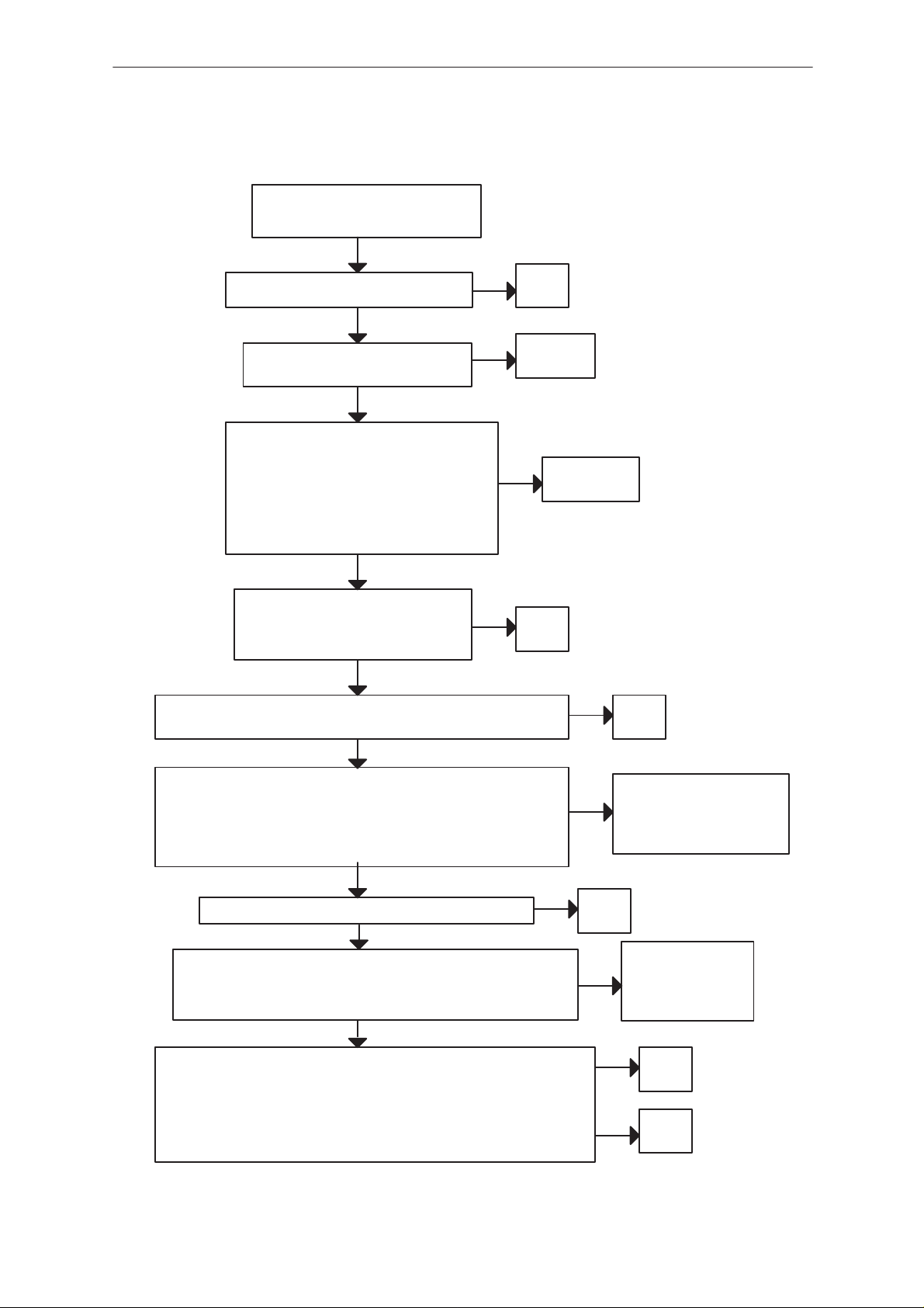
Phone is totally dead
YES
Tp5
VBAT is 3.6 V
YES
Voltage at pin 29 of CCONT (N150)
is 3.6 V
YES
N 150 pin 55 (VBB) 2.8 V(=TP14)
N150 pin 25 (VXO) 2.8 V/TP10)
when PWR switch is pressed
or watchdog disable pin is grounded
YES
See section: Power Doesn’t Stay On
NO Failure in VBAT line
Disassembly & Troubleshooting Instructions
Check X105, X104, Z100
NO
Faulty circuit N150
NO
CCONT (N150) pin 29 0V when
PWR switch is pressed or
watchdog disable pin is (X101)
grounded
Faulty circuit N150
YES
Check R164, X102
NO
Check UI module
Check watchdog disable line to
X101
Flash programming doesn’t work
The flash programming can be done via panel connector X101 or via system
connector X100.
The main differences between these are:
a) FLASH programming voltage is produced different way.
b) Signal routings are different.
In flash programming error cases the flash prommer can give some information about a fault.
The fault information messages could be:
– MCU doesn’t boot
– Serial clock line failure
– Serial data line failure
– External RAM fault
– Algorithm file or alias ID doesn’t find
– MCU flash Vpp error
In cases that the flash programming doesn’t succeed there is a possibility to
check short circuits between the memories and the MCU (MAD1).
This test is useful to do, when the fault information is: MCU doesn’t boot, Serial clock line failure or Serial data line failure.
Original 09/98
Page 13
Page 14

NSC/W–1/3
PAMS
Disassembly & Troubleshooting Instructions
Flash progrmming doesn’t work
YES
If the fault information from the prommer is:
External RAM fault
YES
Check pins of SRAM (D200)
Check control lines of SRAM:
RAMSelX ...
Flash progrmming doesn’t work
YES
If the fault information from the prommer is:
Algorithm file or alias ID doesn’t find, ID is
unknown etc.
YES
Technical Documentation
Check pins of FLASH (D201)
Check control lines and upper data lines (15:8)
of FLASH: ROM1SelX...
Flash progrmming doesn’t work
YES
If the fault information from the prommer is:
MCU flash Vpp error
YES
Vpp > 2.8 V in D201 pin 13)
YES
Check pins of FLASH D201
OK
Faulty component D201
NO
Vpp > 2.8 V in pin 13 of D201
YES
Check UI connector X102
Page 14
Original 09/98
Page 15

PAMS
NSC/W–1/3
Technical Documentation
Disassembly & Troubleshooting Instructions
Power doesn’t stay on, or phone is jammed
If this kind of fault has come after flash programming, there are most probably open pins in ICs.
The soldered joints of ICs: D202 (MAD1), D201 (FLASH), N150 (CCONT),
D200 (SRAM) are useful to check first.
Normally the power will be switched of by CCONT (N150) after 30 seconds,
if the watchdog of the CCONT can not be served by software.
The watchdog updating can be seen by oscilloscope at pin 50 (DataselX) of
CCONT.
In a normal case there is a short pulse from ”1” –> 0 every 8 seconds.
The power off function of CCONT can be prevented by connecting a short
circuit wire from CCONT pin 29 to ground.
Original 09/98
Page 15
Page 16

NSC/W–1/3
PAMS
Disassembly & Troubleshooting Instructions
Power doesn’t stay on or phone is jammed
YES
CCONT watchdog is served?
(pin 50 pulses 1 –> 0)
NO
connect the shortcircuit fire from N150 pin 29 to ground (watchdog)
OK
EEPROM (D203) pin 8 (VBB) 2.8 V
G850 pin 3
YES
check R272
YES
TP 23 19.44 MHz sine
wave 500 mV min
NO
check buffer V850 and
VCXO G850
TP 18 master reset (Purx) = ”1”(2.8 V)
YES
NO
TP 23 (N250) pin 2: 19.44 MHz sine wave
Clock signal: 500 mV Vpp typ.
TP24 (N250) pin 63: 9.72 MHz Square wave
clock signal 2.80 Vpp
YES
Technical Documentation
software is able to run
YES
NO
NO TP 20 sleep clock(SCLK)
check UI module
If power is switched off
after few seconds, check
BSI and BTEM lines
VBAT is correct
YES
3.6 V
square wave 32 kHz
YES
Faulty circuit N150
or over loaded PurX line
N150 is faulty
check sleep
NO
clock circuitry
(B150, R156..)
Open pins or faulty circuit:
D202, D200, D201, N150
R212
Page 16
Original 09/98
Page 17

PAMS
NSC/W–1/3
Technical Documentation
Disassembly & Troubleshooting Instructions
Display Information: Contact Service
This fault means that software is able to run and thus the watchog of CCONT
(N150) can be served.
Selftest functions are run when power is switched on and software is started
to excute from flash.
If any of selftests is failed, contact service information will be shown on display .
Original 09/98
Page 17
Page 18

NSC/W–1/3
PAMS
Disassembly & Troubleshooting Instructions
Audio failure
Uplink (microphone) and downlink (speaker) are broken
YES
Voltage at pin 78 of MAD1 (D202)
is 2.8 V (without external audio devices) HOOK.
YES
Voltage at pin 77 of MAD1 (D202)
is 2.8 V (without external audio devices) HEADSETINT
YES
Frequency at pin 5 of MAD1 (D202)
is 1 MHz, square wave 2.8 Vpp
YES
NO
Check
R260, R270
NO
R268, R265, R260
NO
Technical Documentation
Check
Check
N250 (Cobba)
Frequency at pin 6 of MAD1 (D202)
is 8 kHz, square wave pulses 2.8 Vpp
Uplink (microphone) is broken
YES
Voltage at pin 6 of X100 is 1.8 V
Voltage at pin 7 of X100 is 0.3 V
during a call
YES
DC voltage at pins 38 and 39 of
N250 is 1.4 V during a call
YES
Analog audio signal (few millivolts) at pins 38 and 39
of N250 during a call
YES
Digital PCM data at pin 12 of MAD1 (D202)
during a call
NO
NO
NO
Check
N250 (Cobba)
Check
microphone, X100 and micbias
components V250...
If OK, check that VR1_sw is 2.8 V
during a call
Check
N250 (Cobba)
NO
NO
Check
C256, c285 and PCB
routings
Check
N250 (Cobba)
Page 18
Original 09/98
Page 19

PAMS
NSC/W–1/3
Technical Documentation
Downlink (speaker) is broken
Digital PCM data at pin 50 of Cobba (N250)
during a call
DC voltage at pins 28 and 29 of
N250 is 1.4 V during a call
Analog audio signal (some ten millivolts) at pins 28
and 29 of N250 during a call
YES
YES
YES
Disassembly & Troubleshooting Instructions
NO
NO
N250 (Cobba)
Check
D202 (MAD1)
Check
NO Check
N250 (Cobba)
Original 09/98
Page 19
Page 20

NSC/W–1/3
PAMS
Disassembly & Troubleshooting Instructions
Charging failure
Nothing happens when charger is connected
YES
Voltage level at pin 60 of CCONT (N150)
is higher than 0.4 V when charger is connected
YES
Check N150
Display Information: Not charging
YES
Voltage level at pin 62 of CCONT (N150)
is about 0.8 V when power is connected
BSI resistor value should be 39 k
YES
Technical Documentation
NO
Check
X100, R164, R152,
F150
NO Check
X104, R152, R163
Voltage level at pin 63 of CCONT (N150)
is about 0.5 V when power is connected
BTEMP resistor value should be 47 k
YES
32 Hz square wave frequency at pin 7 of CHAPS (N151)
YES
Voltage levels at pins 5 and 12 of CHAPS (N151)
are same as VB
YES
Voltage levels at pins 5 and 12 of CHAPS (N151)
rises when charger is connected
NO
NO
NO
NO
Check
X104, R163, R161
Check
N150
Check
R153, N151
Check
N151
Page 20
Original 09/98
Page 21

PAMS
NSC/W–1/3
Technical Documentation
Receiver Fault AMPS
General Instructions
Start the WINTESLa software and use it to start the needed RX mode of the
phone. The troubleshooting flow chart is divided into three steps:
– general checking,
– local checking
– RX-chain checking.
Make sure to check all solderings and the presence of all components before
changing an ASIC or filter.
Path of the received signal
Block level listing:
Path of the received signal
Disassembly & Troubleshooting Instructions
Antenna EXT RF
Duplexer
Low Noise Amplifier (LNA)
RX Filter
First Mixer
116.19 MJz filter
IF amplifer
ACG/Buffer
Second mixer
450 kHz fillter
Buffer/limiter
Baseband (FM detector)
The following fault finding charts are for the receiver chain.
Original 09/98
Page 21
Page 22

NSC/W–1/3
PAMS
Disassembly & Troubleshooting Instructions
Receiver Fault AMPS
Apply 879.00 MHz
–116dBm, 8kHz dev 1
kHz sine signal to
external RF–connector
X991.
Connect EXT HS to
audioanalyzator , open
audio
AF: 1 kHz sine signal,
meas SINAD
Check UHF Vcnt
TP31
V: 2.0 ..2.5 V
Check 3 multiplier
output level TP2LU
n750, pin 42
V: >150 mVpp ?
AF: >12dB
N
Y
N
Y
N
N
AMPS
RX Chain OK
Start synthesizer
troubleshooting
Start synthesizer
troubleshooting
Technical Documentation
Apply 879.00MHz
–50dBm sine sign.
to external RF
connector X991
Y
Check input level
at duplex filter (Z910)
input P:
Y
Check input level at
frontend (N701) input
pin7
P:
Y
Check output level at
LNA out
pin10
P:
N
N
N
Change EXT RF
Connector
Change duplex filter or
Change N701
L701
Note!
Check all soldering and components
in antenna circuit before changing
Note!
Check all soldering and discrete
components of frontend.
Note!
AG2 is on
Page 22
Y
Check MXR RF level
pin12
P:
Y
N
Change RX band filter
Note!
Check all solderings
Z701
Original 09/98
Page 23

PAMS
NSC/W–1/3
Technical Documentation
Y
Check MXR IF level,
F= 116.19 MHz
P:
Y
Check input of
IF amplifier
V741
P:
Y
Check IN_a level
N750, pin 49, 50
P:
N
N
N
Disassembly & Troubleshooting Instructions
Check input level
of front end N701
pin 1
f=995.19MHz
Y
Change N701
Change N701
Change Z741
Check Resistors R743
&R744
Note!
Start synthesizer
troubleshooting
Note!
Check all components around of N701
Note!
Check all components around of filter,
Measure IF–amplifier biasvoltage (TP8LU)
, should be about x.x V if not, change
V741
Note !
Check all discrete components and
voltages around of PLUSSA
Y
Check LIMOUT1
output pin 32
V: >300 mVpp
Y
Check COBBA_D IF2A
Input (TP9L)
V:
N
Change PLUSSA
N
Change resistors R788
& R789
Original 09/98
Page 23
Page 24

NSC/W–1/3
PAMS
Disassembly & Troubleshooting Instructions
Receiver Fault TDMA800
Apply 879.00 MHz
–50dBm signal to
external RF–connector
X991.
Check RF level of
COBBA_D pin no 10
Check UHF Vcnt TP31
P:
N
N
V: 2.0...2.5 V
Y
Check 3 multiplier
output level TP2LU
N750, pin 42
Y
N
N
TDMA800
RX–chain OK
Start synthesizer
troubleshooting
Start synthesizer
troubleshooting
Technical Documentation
V: >150 mVpp
Y
Check input level
at duplex filter (Z910)
input
P:
Y
Check input level at
frontend (N701) pin 7
P:
Y
Check output level at
LNA out, pin 10
P:
Y
Check MXR RF level
pin 12
P:
N
N
N
N
Change EXT RF
Connector
Change duplex filter or
Change N701
Change RX band filter
L701
Z701
Note!
Check all soldering and components
in antenna circuit before changing
Note!
Check all soldering and discrete
components of frontend.
Note!
AG2 is on , TP1 1LU
N
Note!
Check all soldering
Page 24
Y
Check all components around of N701
Original 09/98
Page 25

PAMS
NSC/W–1/3
Technical Documentation
Check MXR IF level,
F= 116.19 MHz
pin 14
P:
Y
Check input of
IF amplifier
V741
P:
Y
N
N
Check input level of
front end N701,
pin 1
f=995.19MHz
Y
Change N701
Change Z741
Disassembly & Troubleshooting Instructions
N
Note!
Start synthesizer
troubleshooting
Note!
Check all components around of filter,
Measure IF–amplifier biasvoltage, should
be about x.x V if not change V741 (TP8LU)
Check IN_rx level
N750, pin 51, 52
P:
Y
Check OUTP_rxif level
N750 Pin 29,30
P:
Y
Check COBBA_D IF2D
N250, pin 9, 10
P:
N
Check Resistors R743
&R744
Note !
N
Change PLUSSA
Check all discrete components and
supply voltages of PLUSSA..
Check also AGC1 line. (TP10LU)
N
Change capacitors
C790 & R789
Original 09/98
Page 25
Page 26

NSC/W–1/3
PAMS
Disassembly & Troubleshooting Instructions
Receiver Fault TDMA1900 (only for dualbander)
Apply 1960.02 MHz
–50dBm signal to
external RF–connector
X991.
Check RF level of
COBBA_D pin no 10
P:
N
N
Check UHF Vcnt
TP5U
V: 2.0...2.5V
N880, pin 3
Y
Check 3 multiplier
output level TP2LU
V: >150 mVpp
N750, pin 42
Y
N
N
TDMA1900
RX–chain is OK
Start synthesizer
troubleshooting
Start synthesizer
troubleshooting
Technical Documentation
Y
Check input level
of duplex filter (Z960)
P:
Y
Check input level of
frontend N721
pin 7
P:
Y
Check output level at
LNA out pin 10
P:
Y
Check MXR RF level
pin 12
N
N
N
N
Change EXT RF
Change duplex filter or
Change RX band filter
Connector
L721
Change N721
Z726
Note!
Check all soldering and components
in antenna circuit before changing
Note!
Check all soldering and discrete
components of frontend.
Note!
AG2 is on
N
Note!
Check all soldering
Page 26
P:
Y
Check all components around of N721
Original 09/98
Page 27

PAMS
NSC/W–1/3
Technical Documentation
Check MXR IF level,
F= 116.19 MHz
P:
Y
Check input of
IF amplifier
V741
P:
N
Check input level fo
front end N721, pin 1
f=2076.21 MHz
Change N721
Change N721
N
Change Z741
Disassembly & Troubleshooting Instructions
Note!
Start synthesizer
troubleshooting
Note!
Check all components around of filter,
Measure IF–amplifier biasvoltage, should
be about 1.3 V if not change V741
Check all components
around N721
Y
Check IN_rx level
N750, pin 51, 52
P:
Y
Check OUTP_rxif level
N750, pin 29, 30
P:
Y
Check COBBA_D IF2D
N250, pin 9, 10
P:
N
Check Resistors R743
&R744
Note !
N
Change PLUSSA
Check all discrete components and
supply voltages of PLUSSA .
Check also AGC1 line.
N
Change capacitors
C790 & R789
Original 09/98
Page 27
Page 28

NSC/W–1/3
PAMS
Disassembly & Troubleshooting Instructions
Transmitter Fault – General
Always use a RF–cable connected from an external RF connector to the
analyzer via RF–power attenuator. This is important to protect the analyzer
against excessive RF power and to not let unwanted RF power leak in the
cellular frequencies.
Start the WINTESLA software and select the TX mode for testing (AMPS,
DAMPS, or TDMA 1900). Select mid channel (383 for AMPS, DAMPS or
1000 for TDMA 1900) Select random data for digital mode of operation.
One of the basic test is to monitor current when transmitter is on. If the current consumption does not change when transmitter is turned on, the fault
is in the PA. Also if pressing the PA chip more tightly to PCB does have an
effect on current consumption, the fault is in PA.
In case of a faulty PA the IC can be changed only under correct (ESD)
grounding and using only a hot air blower set to 10m/s and 300 degree centigrade. The new chip must be taken from its vacuum package and the heating
process must be done in less than 30 second. Note that the bottom plate of
the chip must be properly soldered and excessive solder material, if any , has
to be remove.
Technical Documentation
Path of the transmitted signal
Block level listing AMPS, DAMPS Block level listing TDMA 1900
COBBA TX I/Q DA–converters COBBA TX I/Q DA–converters
I/Q modulator and Digital gain step amplifier I/Q modulator and Digital gain step amplifier
IF–BPF IF–BPF
Upconverter Upconverter
TX Driver BPF
BPF TX Driver
PA BPF
Coupler PA
Duplex filter Coupler
Antenna matching circuit Duplex filter
EXT RF connector Antenna matching circuit
Antenna EXT RF Connector
Antenna
Power detection and power control circuit are included in the power control
part of this guide.
Page 28
Start the WINTESLA software and set the phone in Analog mode. Set Channel 383 and Power level 2. Apply the RF cable to Ext RF onnector and connect the cable to the spectrum analyzer input, measure the RF level. Notice
the insertion loss of the cable and the attenuators. Use external attenuator
to avoid overloading the spectrum analyzer.
Original 09/98
Page 29

PAMS
NSC/W–1/3
Technical Documentation
Transmitter Fault AMPS
AMPS, PWL2, CH383
Check current
consumption:
I: >800 mA
N
Press down PA–module
Inreasing current
consumption ?
N
Y
Y
Disassembly & Troubleshooting Instructions
Check Antenna Circuit
and Duplex filter
Replace P A,
check for eventual
delamination
Note!
Check all supply voltages and soldering
Check also N900 pin3 frequency and
input power. Should be > –10 dBm and
f = 997.68 MHz. If not start synth trouble
shooting (tx–local are missing)
Check V APC
V: >2.5 V
N
Check TXC
V: >1.5 V
Y
Start Power control
troubleshooting
Y
N
Check PA input PWR
P: > 0 dBm
N
Check Band passfilter
insertion loss
(max. 4dB)
N
Is TX driver input OK?
P: > –20 dBm
N
Y
Change P A
Y
Check Z901, R907 and
C929
Y
Change N902
Check COBBA
TXCDAC
(Baseband)
Original 09/98
Page 29
Page 30

NSC/W–1/3
PAMS
Disassembly & Troubleshooting Instructions
Check TXIF Z900 Pin7
f: 161.19 MHz
P: >–25 dBm
N
Is Z900 Insertion too
high ?
I.L : max 2 dB
Y
Y
Change N900
upconverter
Change Z900
Technical Documentation
N
Check modulator
output N750 pin62
P: max.–18dBm
Y
Is TX I/Q OK?
V: 0.8 VDC +/– 0.4 V
(symmetrical)
Y
Change N750
N
N
Check R906
Note!
check also I/Q–resistors
Check COBBA
I&Q DACs
(baseband)
Page 30
Original 09/98
Page 31

PAMS
NSC/W–1/3
Technical Documentation
Transmitter Fault TDMA800
The transmitter is the same as in AMPS mode, but the power amplifier is
biased to more linear. Consequently it is essential that the AMPS is free of
any faults.
Is AMPS mode OK ?
Y
Check Vbias PIN16
N903
V: > 2.7 V
Disassembly & Troubleshooting Instructions
N
N
Start AMPS
troubleshooting
Check CCONT
VR7_bias
(baseband)
Y
Start modulator output
tuning. Is one gain step
2 dB in the output
power ?
N
Change N750
Original 09/98
Page 31
Page 32

NSC/W–1/3
PAMS
Disassembly & Troubleshooting Instructions
Transmitter Fault TDMA1900
TDMA1900 and DAMPS modes share a common IF section and antenna circuit. Consequently it is essential that the DAMPS mode is free of any faults.
N
Is TDMA800 mode OK
?
Y
N
Is locals OK ?
Start TDMA800
troubleshooting
Start synth
troubleshooting
Technical Documentation
Note!
Check VHF and UHF locals including
Lo–buffer, measuring point for UHF is
N980 pin5.
Y
Check current
consumption
I: > 450mArms
N
Make press down test
for PA. Inreasing
current consumption ?
N
Y
Check antenna circuit
and Duplex–filter
Short circuit in PA?
Y
Replace PA,
check for
delamination
Page 32
Original 09/98
Page 33

PAMS
NSC/W–1/3
Technical Documentation
Check V APC
V:>2.5 V
N
Check TXC
Typ 1.5V@PL2
Y
N
Y
Check PA input power
P:> 0 dBm
Check Bandpassfilter
insertion loss
Max 4 dB
Disassembly & Troubleshooting Instructions
Y
Change P A
N
Y
Change BPF
N
Start power control
troubleshooting
CHeck COBBA
TXCDAC
(BaseBand)
Check TX–driver input
P:> –20 dBm
N
Check
R981upconverter
output
P:> –20dBm
N
Change N950
Y
Y
Check Z950 and
pii–attenuator
Original 09/98
Check TX–IF
P:> –25 dBm
f: 196.23 MHz
N
Check Z900 Insertion
loss, if less than 2 dB
change N750
Page 33
Page 34

NSC/W–1/3
PAMS
Disassembly & Troubleshooting Instructions
Power Control Loop
Power control section is basically similar for both band except both bands
include a coupler and detector. The power control is actually ef fected in the
PLUSSA IC.
Check V930 and V929
Check Bias circuit
at the diodes
Check PIN diode bias
components
Check BB controls
(BaseBand)
Is V930 voltage drop
about 0.3 ...0.4 V?
N
Is TXLX functionality
OK ?
TXLX is LOW during
PL 7 to PL2
Y
Y
N
Technical Documentation
Note !
See Udet vs. Output power curve
Note !
1. Gain control voltage of driver
is directly proportional to output
power and TXC voltage in AMPS
MODE.
2. Gain coltrol voltage of driver
will remain same (+/– 2dB typ.)
regardless of power level and
TXC voltage in DIGITAL MODE.
3. Udet and TXC will be about
same in each mode.
Is Udet vs, output
Is Udet vs. output
power and TXC
OK?
Typical detected voltage level at different power levels, +32 C:
HD961/HD963
LB:
PL 10 –348 0.36736
UB:
PL 10 –352 0.3584
N
Replace N750:
Check power
controls in
components near
N750
TXC
9 –319 0.43232
8 –283 0.51296
7 –324 0.42112
6 –291 0.49504
5 –243 0.60256
4 –170 0.76608
3 –61 1.01024
2 106 1.38432
TXC
9 –313 0.44576
8 –259 0.56672
7 –291 0.49504
6 –262 0.56
5 –225 0.64288
4 –163 0.78176
3 –46 1.04384
2 74 1.31264
NOTE: DAC VALUES MAY VARY +/– 150 DAC UNITS
1.4
1.2
1
0.8
0.6
0.4
0.2
0
10987 65432
4. TXA is high during modulation (any).
5. TXLX signals will carry about 4mA
in HIGH state.
Series1
Series2
PL
Page 34
Original 09/98
Page 35

PAMS
NSC/W–1/3
Technical Documentation
Synthesizers
There are four oscillators generating the needed frequencies for RF–section. They are
19.44 MHz reference oscillator,
1GHz UHF VCO,frequency range 985.23 ... 1010.2 MHz
2Ghz UHF VCO frequency range 2046.2 ... 2107.2 Mhz
VHF VCO.has two fixed frequencies, 322.38 Mhz for lowband
VHF VCO operating frequency is controlled by the BAND–signal and the
PLL–circuit of the PLUSSA. All locals are locked to a stable reference oscillator.
A practical way to check the synthesizer status is measuring the control voltage of the VCO from the Integrator capacitor. If the voltage is stable and
reasonable, the local oscillators are running correctly.
Disassembly & Troubleshooting Instructions
392.46 for upper band
19.44 MHz reference oscillator
The 19.44 MHz oscillator frequency (G850)is controlled by the COBBA_D.
This signal is fed to the PLUSSA and TDMA1900 PLL circuit. All synthesizers use the divided signal as reference signal for the phase locked loop to
provide a correct LO frequency . The VCTCXO output signal is also used to
generate the 2LO frequency by multipliers.
The baseband clock signals are generated from this signal. The VCTCXO
output signal is buffered and connected to MAD2.
58.32 MHz 3–multiplier
The 3–multiplier is a discrete circuit which is used to generate the second
local frequency for the receiver . The multiplier output signal is connected to
the PLUSSA IN_X2 pin. In the PLUSSA the signal is multiplied by 2 and then
fed to the 2nd mixer.
Original 09/98
Page 35
Page 36

NSC/W–1/3
PAMS
Disassembly & Troubleshooting Instructions
Technical Documentation
19.44 MHz oscillator and 3–multiplier troubleshooting
VCTCXO
OUTPUT :
19.44 MHz
P:>0.8Vpp
Check
AFC–signal from
C850
P: 1.1 V
N
Change G850
Check resistor
R850
Note!
Check all soldering and supply voltages
for VCTCXO and RFC–buffer.
Check also coil L850 & C858.
Check PLUSSA
(N750) pin 21
P: >0.8 Vpp
Check 2G PLL
(N880) pin 15
P: >0.8 Vpp
Check
RFC–buffer
output
P: >0.3 Vpp
Check 3X output
P: >150 mVpp
Change capacitor
C852
Change capacitor
C851
Change capacitor
C853
Change capacitor
C854
Note !
Check all solderings and components of buffer .
Note!
Check all soldering and components of multiplier.
Check also Vce, should be 1 V if not change V840
VHF VCO
The VHF VCO signal is used to generate the transmitter intermediate frequencies. The VHF VCO has two fixed frequencies. The operating frequency is locked in phase locked loop which is controlled by the baseband
Page 36
Original 09/98
Page 37

PAMS
NSC/W–1/3
Technical Documentation
Because the oscillator employs two frequencies it also has two diferent
switching modes. These modes are controlled by the BAND signal. In
AMPS and TDMA800 modes the frequency is 322.38 MHz and the logical
level of the BAND signal is ”HIGH”. In TDMA1900 mode a higher if is needed
and the operating frequency is increased to 392.46 MHz. The BAND signal
is also set to logical level ”zero”
The VHF VCOoutput signal is fed to the PLUSSA LO pin no.8. In the PLUSSA the signal is divided for the phase detector and TX elements. Before being fed to the I/Q–modulator the frequency is divided by 2.
VHF VCO troubleshooting
Is oscillator
locked ?
N
Y
Disassembly & Troubleshooting Instructions
Note!
Change
PLUSSA
Check BAND–signal status
”1” = TDMA800&S
”0” = TDMA1900
Check oscillator
output level
P:
N
Check V800 Vce
pin2
P:
Y
Check V800 Vce
pin5
P:
Y
Check D801
P: opposite of
BAND
Check PLUSSA (N401)
Y
N
pin 54 (SCLK):2.8V
pin 55 (SDA TA):2.8V
pin 56 (SENA1):2.8V
SENA is 0 during SCLK
and SDA TA
Change V800
Change D801
Note!
SENA1 = PLUSSA PLL
SENA2 =
Note!
Check all solderings and
missing components
Note!
Check all components and soldering
2G PLL (N880, pin 13)
Original 09/98
Page 37
Page 38

NSC/W–1/3
PAMS
Disassembly & Troubleshooting Instructions
AMPS & TDMA UHF SYNTHESIZER
The 1GHz UHF VCO (G820) generates the first injection for RX
(869...897MHz) and the final injection for TX (824...849 MHz) . The output
frequency of the module depends on thje DC control voltage supplied by the
PLUSSA.
1GHz UHFsynthesizer troubleshooting
Is Frequency
locked ?
N
What is VCO output
levet ?
P:
N
Change G820
Technical Documentation
Note!
Frequency = 985.23...1010.2
Vcnt = 1.2...3.6 V
Note!
Check all soldering & missing components
Y
Check local input
level of frontend
(N701, pin 1)
Check feedback
input level of
PLUSSA
(N750, pin 21)
Check PLUSSA (N750)
pin 54 (SCLK):2.8V
pin 55 (SDATA):2.8V
pin 56 (SENA1):2.8V
SENA is 0 during SCLK
and SDATA
N
P:
Y
P:
N
Change R821
N
Change C821
Page 38
Original 09/98
Page 39

PAMS
NSC/W–1/3
Technical Documentation
Disassembly & Troubleshooting Instructions
TDMA1900 UHF Synthesizer 2 GHz (ONLY DUALBANDER)
The 2GHz UHF synthesizer generates the needed injection frequencies for
TX and RX chain. The output frequency of the VCO depends on the control
voltage supplied by the PLL circuit.
2 GHz UHF synthesizer troubleshooting
Note!
Is Frequency
locked ?
N
What is VCO output
levet ?
P:
N
Change G820
Frequency = 985.23...1010.2
Vcnt = 1.2...3.6 V
Note!
Check all soldering & missing components
Y
Check local input
level of frontend
(N701, pin 1)
Check feedback
input level of
PLUSSA
(N750, pin 21)
Check PLUSSA (N750)
pin 54 (SCLK):2.8V
pin 55 (SDATA):2.8V
pin 56 (SENA1):2.8V
SENA is 0 during SCLK
and SDATA
N
P:
Y
P:
N
Change R821
N
Change C821
Original 09/98
Page 39
Page 40

NSC/W–1/3
Á
ББББББ
Á
Á
Á
ББББББ
ББББББ
ББББББ
ББББББ
ББББББ
ББББББ
ББББББ
ББББББ
ББББББ
ББББББ
ББББББ
ББББББ
ББББББ
ББББББ
ББББББ
ББББББ
ББББББ
ББББББ
ББББББ
ББББББ
ББББББ
ББББББ
ББББББ
ББББББ
ББББББ
ББББББ
PAMS
Disassembly & Troubleshooting Instructions
About RF ASICs and MMIC PA
General information
The PLUSSA (N750) provides two main functions:
1. RX/TX blocks
2. PLL
The receiver block consists of IF buffers, active mixers, 2–multiplier, AGC
amplifier and limiter.
The transmitter section includes a digital gain step amplifier, a divider , an
I/Q Modulator and control part for the Transmitter Power Control loop.
The PLL section is controled via the serial bus and contains both UHF and
VHF PLL and predividers.
PLUSSA ASIC
Technical Documentation
Pin #
ÁÁ
1
2
3
4
5
6
7
8
9
10
11
12
13
14
15
16
17
18
19
20
21
22
23
24
25
26
27
Pin name
БББББ
TXP_pwc
TXA_pwc
INPi_tx
INMi_tx
INMq_tx
INPq_tx
GND_P1
LO
VP1
VOP
TXC_pwc
DET_pwc
TXI_pwc
opain_pwc
opaout_pwc
OUT_pwc
VCE1
PD
VSE1
DGND
OSC
VDD
GND_P2
U_in
VP2
VSE2
PD2
Nomi-
nal lev-
ÁÁ
el
2.8V
2.8V
0.8V
0.8V
0.8V
0.8V
0
?
2.8V
2.8V
0.5–2V
?
–
–
–
~5V
?
0
0
?
2.8V
0
0dBm
2.8V
0
–
Description
ББББББББББББББББББ
TX power control enable
TX power loop control mode
Positive I–channel input of the TX
Negative I–channel input of the TX
Positive Q–channel input of the TX
Negative Q–channel input of the TX
Ground
VHF VCO signal
VHF prediv supply voltage from CCONT
Positive supply voltage for the 1st opamp in pwrcnrl
Power level control of the TX
Feedback from the peak detector diode
False transmission indicator
Input for the 2nd opamp in the pwr cntrl loop
Opamp output for external feedback
Output voltage for TX–driver
VHF charge pump V5V–signal from BB
VHF charge pump output
Ground for VHF charge pump
Digital ground
19.44 MHz–signal from G850
Positive supply for digital parts
Ground for UHF predivider
UHF VCO signal from G820
Positive supply for UHF predivider
Negative supply for UHF charge pump
UHF charge pump output
Page 40
Original 09/98
Page 41

PAMS
ББББББ
ББББББ
ББББББ
ББББББ
ББББББ
ББББББ
ББББББ
ББББББ
ББББББ
ББББББ
ББББББ
ББББББ
ББББББ
ББББББ
ББББББ
ББББББ
ББББББ
ББББББ
ББББББ
ББББББ
ББББББ
ББББББ
ББББББ
ББББББ
ББББББ
ББББББ
Á
ББББББ
Á
Á
Á
Á
ББББББ
Á
Á
Á
Á
ББББББ
Á
Á
Á
ББББББ
ББББББ
ББББББ
ББББББ
ББББББ
ББББББ
ББББББ
NSC/W–1/3
Technical Documentation
28
29
30
31
32
33
34
35
36
37
38
39
40
41
42
43
44
45
46
47
48
49
50
51
52
53
54
55
ÁÁ
56
ÁÁ
57
ÁÁ
58
59
60
61
62
63
64
VCE2
OUTP_rxif
OUTM_rxif
LIMOUT2
LIMOUT1
RSSI
INM_rxif
INP_rxif
LIMIN2
LIMIN1
LIMD1
UB_a2
VRX_limi
GND_if2
IN_X2
Vcc_x2
OUTP_rx
OUT_rx_a
UB_a1
VRX
GND_if1
INP_a
INN_a
INM_rx
INP_rx
GC_rx
SCLK
SDAT
БББББ
SLE
БББББ
VB2_rx
БББББ
VB_ext
IB
GND
OUTN_tx
OUTP_tx
VTX
LO_out
0.8–2V
0.8–2V
0.8–2V
~5V
?
?
–
–
–
?
?
–
0
–
–
?
–
2.8V
0
–
–
–
–
?
ÁÁ
ÁÁ
0
ÁÁ
1.5V
0
0
?
?
2.8V
Disassembly & Troubleshooting Instructions
V5V–signal for UHF charge pump from BB
Positive output of the receiver output gain stage
Negative output of the receiver output gain stage
Negative output of the limiter amplifier
Positive output of the limiter amplifier
Received signal strenght indicator voltage
Negative input of the receiver output gain stage
Positive input of the receiver output gain stage
AC ground of limiter offset comp feedback
Limiter amplifier input
AC ground of limiter offset comp feedback
Filtering cap for bias of lim amplifier
Positive supply of lim amplifier and RSSI
Ground
Input to x2–frequency multiplier
Positive supply of x2 block
Positive mixer output of the receiver
Positive output of analog mode RX mixer
Filtering cap for bias of analog mode RX
Power supply of the receiver
Ground
Positive input of analog mode rx amplifier
Negative input of analog mode rx amplifier
Negative input of the receiver
Positive input of the receiver
RX gain control signal
Clock for PLL serial programming and digital gain
step amplifier adjusting
Data for PLL serial programming and digital gain
ББББББББББББББББББ
step adjusting
Latch enable for PLL serial programming and digital
ББББББББББББББББББ
gain step adjusting
Connection for filtering capacitor of Bias voltage of
ББББББББББББББББББ
RX&TX
VREF–signal from BB
Internal Bias voltage
Ground
Negative output of the transmitter
Positive output of the transmitter
Positive power supply of the transmitter
Not connected
Original 09/98
Page 41
Page 42

NSC/W–1/3
Á
Á
Á
Á
Á
Á
Á
Á
Á
Á
Á
Á
Á
Á
Á
Á
Á
Á
Á
Á
Á
Á
Á
Á
PAMS
Disassembly & Troubleshooting Instructions
Receiver front ends
Pin #
ÁÁ
ÁÁ
1
2
3
4
5
6
7
8
9
10
11
12
13
14
15
16
Pin name
ÁÁÁ
ÁÁÁ
LO IN
Vdd buf
LO out
GND
Vdd LNA
GND
LNA in
GND
Gain sel
LNA out
GND
Mxr RF
GND
MXR IF
GND
Vdd MXR
Nomi-
ÁÁ
nal lev-
ÁÁ
el
?
2.8V
0
2.8V
0
?
0
0
?
0
?
0
?
БББББББББББББББББ
БББББББББББББББББ
Mixer lo–buffer Vdd and lo–buffer tuning
Technical Documentation
Description
Mixer lo input
Lo–buffer Vdd
Lo–buffer output
ground
LNA Vdd
ground
LNA RF input port
LNA ground
LNA gain select
LNA output port
ground
Mixer RF input port
ground
Mixer IF input port
ground
MMIC Power Amplifiers
Pin #
ÁÁ
ÁÁ
1
2
3
4
5
6
7
8
9
10
11
12
13
14
15
16
Pack-
age
ÁÁ
Base
ÁÁ
Pin name
ÁÁÁ
ÁÁÁ
Vcc
N/C
LTune
Vcc1
GND1
RF IN
N/C
Vreg
N/C
N/C
N/C
RF OUT
RF OUT
2*fo
N/C
Vbias
Ground
ÁÁÁ
ÁÁÁ
Nomi-
ÁÁ
nal lev-
ÁÁ
el
VBAT
VBAT
2.8V
ÁÁ
ÁÁ
БББББББББББББББББ
БББББББББББББББББ
Power supply for bias circuit
–
?
Tuning pin for interstage matching network
Power supply for the 1st stage collector
–
–
Regulated power supply for bias circuit. PA shut
?
?
?
RF output and bias for output stage
RF output and bias for output stage
Second harmonic trap
–
–
Ground connection. The backside of the pack-
age must be connected to the ground plane
БББББББББББББББББ
БББББББББББББББББ
throught a short path
N960
Not connected
Ground
RF input
Not connected
down
Not connected
Not connected
Not connected
Not connected
Bias control 2.8V
Description
Page 42
Original 09/98
Page 43

PAMS
Á
Á
Á
Á
Á
Á
Á
Á
Á
Á
Á
Á
Á
Á
Á
Á
Á
Á
Á
Á
Á
Á
Á
Á
Á
Á
Á
Á
NSC/W–1/3
Technical Documentation
Pin #
ÁÁ
ÁÁ
1
2
3
4
5
6
7
8
9
10
11
12
13
14
15
16
Pack-
age
ÁÁ
Base
ÁÁ
Pin name
ÁÁÁ
ÁÁÁ
N/C
N/C
Vcc/Q2C
Vcc/Q1C
GND
RF IN
GND
Vreg
N/C
Bias
RF OUT
RF OUT
RF OUT
RF OUT
N/C
N/C
Ground
ÁÁÁ
ÁÁÁ
Nomi-
ÁÁ
nal lev-
ÁÁ
el
VBAT
VBAT
2.8V
ÁÁ
ÁÁ
Disassembly & Troubleshooting Instructions
Description
БББББББББББББББББ
БББББББББББББББББ
Power supply for the 2nd stage
Power supply for the 1st stage.
–
?
–
Regulated voltage supply for the bias circuit
?
?
?
RF output and bias for output stage
RF output and bias for output stage
?
–
Ground connection. The backside of the pack-
age must be connected to the ground plane
БББББББББББББББББ
БББББББББББББББББ
RF output matching
Second harmonic trap
throught a short path
N960
Not connected
Not connected
Ground
RF input
Ground
Not connected
Bias ground
Not connected
Not connected
PENTA regulator
Pin #
ÁÁ
ÁÁ
1
2
ÁÁ
3
4
5
6
7
8
9
10
11
12
13
14
15
16
Pin name
ÁÁÁ
ÁÁÁ
Bypass
Common
enable
ÁÁÁ
VR1cntrl
VR2cntrl
VR3cntrl
VR4cntrl
VR5cntrl
GND
VR5
Vcc2
VR4
VR3
VR2
VR1
Vcc1
N/C
Nomi-
ÁÁ
nal lev-
ÁÁ
el
–
?
ÁÁ
2.8V
VBAT
2.8V
2.8V
2.8V
2.8V
VBAT
Description
БББББББББББББББББ
БББББББББББББББББ
Pin for external bypass capacitor
Enable for whole circuit
БББББББББББББББББ
Regulator 1 ON/OFF
Regulator 2 ON/OFF
Regulator 3 ON/OFF
Regulator 4 ON/OFF
Regulator 5 ON/OFF
Ground
Regulator 5 output
VR4 and VR5 common input voltage
Regulator 4 output
Regulator 3 output
Regulator 2 output
Regulator 1 output
VR1, VR2 and VR3 common input voltage
Not connected
Original 09/98
Page 43
Page 44

NSC/W–1/3
Á
Á
Á
Á
Á
Á
Á
Á
Á
Á
Á
Á
Á
Á
Á
Á
PAMS
Disassembly & Troubleshooting Instructions
TDMA1900 UPCONVERTER
Pin #
ÁÁ
ÁÁ
1
2
3
4
5
6
7
8
9
10
11
12
13
14
15
16
Pin name
ÁÁÁ
ÁÁÁ
VDD1
N/C
N/C
GND
LO IN
GND
RF OUT
VDD2
N/C
N/C
GND
VDD3
GND
IF IN
N/C
TX ENA
Nomi-
ÁÁ
nal lev-
ÁÁ
el
2.8V
0
?
0
?
2.8V
–
–
2.8V
0
–
–
БББББББББББББББББ
БББББББББББББББББ
Intermediate frequency input
Technical Documentation
Description
Supply voltage
Not connected
Not connected
Ground
TX local input
Ground
RF output
Supply voltage
Not connected
Not connected
Ground
Supply voltage
Ground
Not connected
TX enable
TDMA1900 PLL
Pin #
ÁÁ
ÁÁ
1
2
3
4
5
6
7
8
9
10
11
12
13
14
15
16
17
18
19
20
Pin name
ÁÁÁ
ÁÁÁ
FAST
CPF
CP
VDD2
Vss3
RFI
Vss2
POL
PON
Vss1
CLK
DATA
E
Vdd1
XTALB
XTALA
GND(CP)
Vcc
Iset
LOCK
Nomi-
ÁÁ
nal lev-
ÁÁ
el
2.8V
2.8V
0
?
0
2.8V
2.8V
0
?
?
?
–
–
–
0
4.8V
–
–
Description
БББББББББББББББББ
БББББББББББББББББ
Enable input for fast chargepump
Fast charge pump output
Normal charge pump output
Power supply voltage
Ground
Main divider input
Ground
polarity select
Power on input
Ground
Programming bus clock input
Programming bus data input
Programming bus enable input
Power supply voltage
Complementary crystal frequency input
Complementary crystal frequency input
Ground for charge pump
Supply voltage for charge pump
charge pump currents setting
Out of lock detector
Page 44
Original 09/98
 Loading...