

Page 1

PAMS Technical Documentation
NSC/W–1/3 Series Transceivers
Tuning Instructions
Original 10/98
Page 2
NSC/W–1/3
PAMS
Tuning Instructions
AMENDMENT RECORD SHEET
Amendment
Number
Date Inserted By Comments
Issue1 05/98 Original
Issue2 10/98
O Juntunen NSC/W–1 data added
Power levels tables added
Easy Flash Concept added
FLE–5 added
Warranty Transfer Instructions added
Repaginated
Technical Documentation
Page 2
Original 10/98
Page 3

PAMS
NSC/W–1/3
Technical Documentation
CONTENTS
Tuning Instructions 4. . . . . . . . . . . . . . . . . . . . . . . . . . . . . . . . . . . . . .
General 4. . . . . . . . . . . . . . . . . . . . . . . . . . . . . . . . . . . . . . . . . . . . .
Required Equipment 5. . . . . . . . . . . . . . . . . . . . . . . . . . . . . . . . . .
Equipment Setup 5. . . . . . . . . . . . . . . . . . . . . . . . . . . . . . . . . . . . .
Equipment Setup for Tuning a Phone
without Removing Covers 6. . . . . . . . . . . . . . . . . . . . . . . . . . . .
Flash Concept for NSC/W-1/3 7. . . . . . . . . . . . . . . . . . . . . . .
Light Flash Concept for NSC/W-1/3 8. . . . . . . . . . . . . . . . . . .
Easy Flash Concept for NSW-1/3 9. . . . . . . . . . . . . . . . . . . .
Tuning With Covers Off – Using Test–frame JBS–19 10. . . .
Tuning With Covers Off – using Light Jig JBT–1 11. . . . . . . .
Warranty Transfer 12. . . . . . . . . . . . . . . . . . . . . . . . . . . . . . . . . .
Warranty Transfer 12. . . . . . . . . . . . . . . . . . . . . . . . . . . . . . . . . . . .
Point of Sale 12. . . . . . . . . . . . . . . . . . . . . . . . . . . . . . . . . . . . . . .
Central of Service 13. . . . . . . . . . . . . . . . . . . . . . . . . . . . . . . . .
Point of Sale 13. . . . . . . . . . . . . . . . . . . . . . . . . . . . . . . . . . . . . . .
Tuning Steps 14. . . . . . . . . . . . . . . . . . . . . . . . . . . . . . . . . . . . . . . . .
1. AFC Tuning (Analog) 14. . . . . . . . . . . . . . . . . . . . . . . . . . . . .
2. VCTCXO Tuning 14. . . . . . . . . . . . . . . . . . . . . . . . . . . . . . . . .
3. Modulator Output ...
LOW BAND / HIGH BAND (only NSW-1/3) 14. . . . . . . . . . .
4. Tx I/Q Modulator Amplitude Balance and
Phase Shift Tuning 15. . . . . . . . . . . . . . . . . . . . . . . . . . . . . . .
5. TX Power... LOW BAND / HIGH BAND 16. . . . . . . . . . . . .
800MHz TX output power 17. . . . . . . . . . . . . . . . . . . . . . . . .
TDMA1900 TX output power 17. . . . . . . . . . . . . . . . . . . . . .
6. RSSI Digital (AGC) ... 18. . . . . . . . . . . . . . . . . . . . . . . . . . . .
7. RSSI Analog ... 18. . . . . . . . . . . . . . . . . . . . . . . . . . . . . . . . . .
8. Rx Audio... 18. . . . . . . . . . . . . . . . . . . . . . . . . . . . . . . . . . . . . .
9. Tx Audio... 19. . . . . . . . . . . . . . . . . . . . . . . . . . . . . . . . . . . . . .
10. Charging... 19. . . . . . . . . . . . . . . . . . . . . . . . . . . . . . . . . . . . .
Tuning Instructions
Original 10/98
Page 3
Page 4

NSC/W–1/3
PAMS
Tuning Instructions
Tuning Instructions
General
All tuning operations of the NSC–1/3 and NSW–1/3 phones are carried
out using the service software. The service software turns the phone into
the locals mode, in which the phone can be outwardly controlled via the
MBUS interface.
Tuning is based on the software communicating with the D/A and A/D
converters of the phone. In some instances the phone processor will also
calculate the required correction parameter.
The tuning values of the phone reside on the EEPROM. The contents of
the EEPROM can be read by the service software and saved as a file.
This is advisable when there is need to retain that information, e.g. in
view of replacement of the circuit. The program also enables writing the
default parameters on the EEPROM, in which case all tuning steps should
be carried out.
Technical Documentation
Note: NSC–1 and –3 do not have upper band componets. NSC–1 and –3
are only 800 Mhz tranceivers.
During tuning, proceed as follows:
– Take care not to damage sensitive measuring instruments with exces-
sive RF power.
– Carry out all tuning steps in the shortest possible time to avoid exces-
sive heating of RF units.
– Perform all tuning steps in the order presented.
– Never try to mask a fault by tuning it out!
Page 4
Original 10/98
Page 5

PAMS
NSC/W–1/3
Technical Documentation
Required Equipment
– PC/AT computer with service software; see separate section for
instructions on installation and use.
– Service accessories; see equipment setup pictures.
– Multimeter or DVM.
– GSM radio telephone test station or separate measuring equipment as
follows:
– RF generator
– pulse power meter
– spectrum analyzer
– attenuator and branching unit
Equipment Setup
Tuning Instructions
Caution: Make sure that you have switched off the PC and the printer
before making connections !
Caution: Do not connect the PKD–1 key to the serial port. You may
damage your PKD–1 !
Attach the protection key PKD–1 to parallel port one (25–pin female
D–connector) of the PC. When connecting the PKD–1 to the parallel port
be sure that you insert the PC end of the PKD–1 to the PC (male side). If
you use a printer on parallel port one, place the PKD–1 between the PC
and your printer cable.
Next connect the M2BUS service cable, DAU–9P, to the serial port
(RS–232) of the computer. Attach one end of the service cable to the PC
serial port and the other end to the service box, JBA–4. For servicing the
phone with the covers in place the service box should always be used.
When the phone covers are removed the jigs should be used.
For audio measurements connect the audio cable, ADS–1, as follows:
– EAR line to AF INPUT of test equipment
– MIC line to MOD GEN OUTPUT of test equipment
Original 10/98
Page 5
Page 6
NSC/W–1/3
PAMS
Tuning Instructions
Technical Documentation
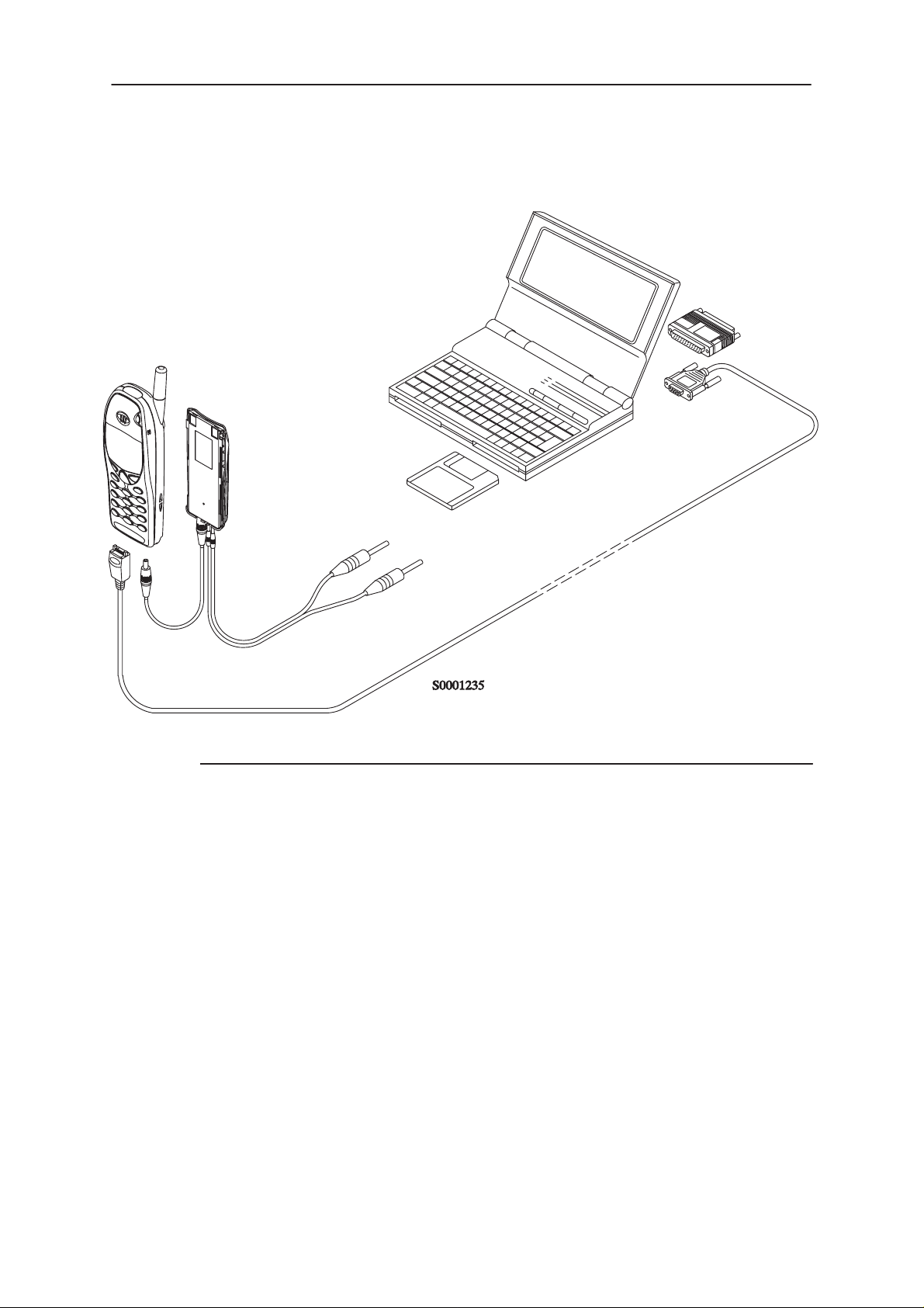
Equipment Setup for Tuning a Phone without Removing Covers
4.
1.
5.
2.
3.
Item: Service accessory: Product code:
1 Service Battery BBD–3 0775071
2 DC Cable SCB–3 0730114
3 Service MBUS Cable DAU–9P 0730109
4 Software protection key PKD–1 0750018
5 Service SW diskette 3.5” for NSC/W–1/3 0774099
WinTesla Service SW application 0774046
Page 6
Original 10/98
Page 7

PAMS
NSC/W–1/3
Technical Documentation
Flash Concept for NSC/W-1/3
12.
4.
5.
1.
6.
Tuning Instructions
10.
13.
11.
9A.
7.
9B. 8.
2.
3.
Item: Service accessory: Product code:
1 Flash Loading Adapter FLA–5 0080178
2 Flash Security Box TDF–4 0770106
3 Prommer FPS–4S 0085095
4 Service Battery BBD–3 0775071
5 Service Cable SCH–5 0730098
6 DC Cable PCC–1B 0730053
7 D15 – D15 Cable AXS–5 0730091
(Included in FLA–5 sales pack)
8 Printer Cable (Included in FPS–4 sales pack) 0730029
9A D9 – D9 Cable AXS–4 0730090
(Included in FPS–4 sales pack)
9B D9 – D9 Cable AXS–4 0730090
10 Software protection key PKD–1 0750018
11 Service SW diskette 3.5” for NSC/W–1/3 0774099
WinTesla Service SW application 0774046
12 Travel Charger ACH–6E (Euro) 0270381
Travel Charger ACH–6U (USA/Japan) 0270382
Travel Charger ACH–6X (UK) 0270380
13 AC Charger ACL–3E 0680015
(Included in FPS–4 sales pack)
Original 10/98
Page 7
Page 8

NSC/W–1/3
PAMS
Tuning Instructions
Light Flash Concept for NSC/W-1/3
11.
10.
5.
3.
Technical Documentation
9.
6.7. 8.
4.
1.
2.
Item: Service accessory: Product code:
1 Flash Loading Adapter FLA–5 0080178
2 Flash Security Box TDF–4 0770106
3 Service Battery BBD–3 0775071
4 Service Cable SCH–5 0730098
5 DC Cable PCC–1 0730053
6 D9 – D9 Cable AXS–4 0730090
7 Light Flash Cable FLC–5 0770107
8 XCM–1 Cable 4626131
9 Software protection key PKD–1 0750018
10 Light Flash SW diskette 3.5” for NSB/C/W–1/3 0774094
11 Travel Charger ACH–6E (Euro) 0270381
Travel Charger ACH–6U (USA/Japan) 0270382
Travel Charger ACH–6X (UK) 0270380
Page 8
Original 10/98
Page 9

PAMS
NSC/W–1/3
Technical Documentation
Easy Flash Concept for NSW-1/3
6.
4.
Tuning Instructions
3.
5.
2
1.
Item: Service accessory: Product code:
1 Flash Security Box TDF–4 0770106
2 Easy Flash Cable FLE–5 0770147
3 Software protection key PKD–1 0750018
4 Easy Flash SW diskette 3.5” for NSW-1/3
5 XCM–1 Cable 4626131
6 Travel Charger ACH–6E (Euro) 0270381
Travel Charger ACH–6U (USA/Japan) 0270382
Travel Charger ACH–6X (UK) 0270380
Original 10/98
Page 9
Page 10

NSC/W–1/3
PAMS
Tuning Instructions
Technical Documentation
Tuning With Covers Off – Using Test–frame JBS–19
3.
4.
9.
6.
1.
8.
7.
5.
2.
Item: Service accessory: Product code:
1 Module Jig JBS–19 * 0770098
2 Service Audio Box JBA–4 ** 0770094
3 DC Cable PCS–1 0730012
4 External Antenna Cable XRC–1B 0730128
5 Service Cable SCH–5 ** 0730098
6 Service MBUS Cable DAU–9S ** 0730108
7 Audio Cable ADS–1 0730011
8 Software Protection Key PKD–1 0750018
Page 10
9 Service SW diskette 3.5” for NSC/W–1/3 0774099
WinTesla Service SW application 0774046
*) The nominal operating voltage for JBS–19 is 3.6 V.
The supply voltage for JBS–19 must never exceed 5.0 V
**) SCH–5, JBA–4, and DAU–9S can be replaced with DAU–9P
Original 10/98
Page 11

PAMS
NSC/W–1/3
Technical Documentation
Tuning With Covers Off – using Light Jig JBT–1
3.
4.
1.
9.
7.
Tuning Instructions
8.
6.
5.
2.
Item: Service accessory: Product code:
1 Light Module Jig JBT–1 * 0770109
2 Service Audio Box JBA–4 ** 0770094
3 DC Cable PCS–1 0730012
4 External Antenna Cable XRC–1B 0730128
5 Service Cable SCH–5 ** 0730098
6 Audio Cable ADS–1 0730011
7 Service MBUS Cable DAU–9S ** 0730108
8 Software Protection Key PKD–1 0750018
9 Service SW diskette 3.5” for NSC/W–1/3 0774099
*) The nominal operating voltage for JBT–1 is 3.6 V.
**) SCH–5, JBA–4, and DAU–9S can be replaced with DAU–9P
Original 10/98
WinTesla Service SW application 0774046
The supply voltage for JBT–1 must never exceed 5.0 V
Page 11
Page 12

NSC/W–1/3
PAMS
Tuning Instructions
Warranty Transfer
Technical Documentation
1.
Item: Service accessory: Product code:
1 Warranty Cable SCH–6 0730099
Warranty Transfer
The Warranty cable SCH-6 is used to connect two phones and transfer
the warranty data (user settings and serial numbers) from one phone to
another.
The warranty transfer procedure is as follows
Point of Sale
Phone 1 is broken.
Number the phones 1 and 2 to avoid mix-up.
Plug the warranty cable SCH-6 to the phones. In this case
phones 1 and 2.
Turn the phone 2 on and then on Silent Profile
Start the warranty data transfer by selecting code
*#92772689# in phone 2.
Page 12
Select option ”Transfer user data?” and press OK
,”Confirm transfer?” Press OK.
Wait untli the transfer is completed.
Turn Phone 2 off, then back on and check welcome note
and profile.
Original 10/98
Page 13

PAMS
NSC/W–1/3
Technical Documentation
After the transfer check with WinTesla the original and
warranty ESN of the phone 2.
Send the broken phone no.1 to the central service.
Central of Service
Check and repair the phone .
Change Warranty State from ”defective” to ”exchange”.
–Win Tesla and PKD–1CS are needed
–Menu Software –> Warranty Info –> Info State –> select
”Exchange”
Send the repaired phone to the dealer.
Point of Sale
Use the returned phone as a swap phone.
Tuning Instructions
When the Warranty Info is transferred into a swap phone
the Warranty State changes to USE mode.
Send the broken phone to the central service.
Original 10/98
Page 13
Page 14

NSC/W–1/3
PAMS
Tuning Instructions
Tuning Steps
1. AFC Tuning (Analog)
This tuning adjusts reference oscillators frequency so that network’s frequency criterias will be met.
This adjustment loads the Analog center frequency DAC value into the
EEPROM. When doing this, a spectrum analyzer must be used.
Note: Do not leave tuning on. The analog transmitting takes maximium
current. The tunning can damage the phone or service battery. The service battery will be heated.
The Spectrum analyzer settings are shown in AFC tuning window.
–Set power supply voltage 8.4 V to service battery (or 3.6 V to jig).
– Connect the spectrum analyzer to antenna connector.
Technical Documentation
– Check that spectrum analyzer frequence is correct.
– Tune the center frequence 832.500 Mhz +/– 200 kHz.
– Once Center frequence (CFR) is correct, press
2. VCTCXO Tuning
This tuning is to check that the radio unit has correct adjustment to meet
networks criteria for frequency stability.
This adjustment loads the VCTCXO DAC value into the EEPROM. RF
generator must be used in this.
The Spectrum analyzer settings are shown in AFC tuning window.
– Set power supply voltage 8.4 V to service battery (or 3.6 V to jig).
– Connect the antenna connector to RF generator.
– Once all RF generator frequency is correct, press
– Set correct RF level to signal generator
– Once frequency and RF level are correct press
OK
button.
Meas button.
( Note: attenuation! )
OK
button.
3. Modulator Output ... LOW BAND / HIGH BAND (only NSW-1/3)
This tuning is to adjust radio unit’s intermediate frequency level so that
RF small signal gain have it’s maximun dynamic range in use with some
drift margin.
– Select
– Set power supply voltage 8.4 V to service battery (or 3.6 V to jig).
Page 14
Tuning –> Modulator output –> Low Band / High Band
Original 10/98
Page 15

PAMS
NSC/W–1/3
Technical Documentation
Tuning Instructions
– Connect pulse power meter or spectrum analyzer to antenna connec-
tor.
– Check that spectrum analyzer frequence is correct (RF information
shows correct frequency)
– Tune the modulator output power to 22dBm.
OK
– Once tuning level is correct, press
button.
4. Tx I/Q Modulator Amplitude Balance and Phase Shift Tuning
This tuning is to adjust IQ–modulators dc–offset and phase error so that
system’s requirements for modulation accuracy will be met.
The purpose of this tuning operation is to adjust the I/Q modulator d.c. offsets and the I/Q modulator amplitude balance and phase shift.
I/Q modulator d.c. offsets, amplitude balance and phase shift tuning:
– Select
Tuning –> TX I/Q...
– Connect spectrum analyzer (with attenuator if needed) to phone an-
tenna connector.
– Check that TX power level is level 10, channel is 60 and TX data type
is 1.
– Adjust spectrum analyzer centre frequency to 830.700 Mhz, and all
other settings are notified by pressing <Settings>.
–9.1125 kHz –9.1125 kHz
D.C. offset
tunings:
Set this value
to minimum
CHF
> 32 dB
> 32 dB
Amplitude &
phase difference:
Set this value
to minimum
– Select the ”TX I d.c. offset” option.
– Adjust the level of centre frequency (CHF signal) to minimum by vary-
ing D/A converter value with
Original 10/98
<–
and –> buttons.
Page 15
Page 16

NSC/W–1/3
PAMS
Tuning Instructions
– The amplitude difference between CHF –9.1125 kHz and CHF should
be >30 dB.
– Select option ”TX Q d.c. offset”.
– Adjust the level of signal CHF to minimum by varying D/A converter
value with
– Use the ”Amplitude Difference” option.
– Adjust the level of signal CFR –9.1125 kHz to minimum by varying D/A
converter value with <– and –> keys.
– The amplitude difference between CHF+67.7 kHz and CHF –67 kHz
should be >35 dB.
– Select the ”Phase Difference” option.
– Adjust the level of signal CHF+67.7 kHz to minimum by varying D/A
converter value with <– and –> keys.
– When values are correct press SAVE button.
<–
and
–>
Technical Documentation
keys.
5. TX Power... LOW BAND / HIGH BAND
NOTE: Use Service Battery connected to 1.5A 8.4V power supply or use
phone’s own battery.
This tuning is to adjust radio unit’s output power level values according to
system specification.
This adjustment loads the power levels of the phone transmitter into the
EEPROM. When doing this, a pulse power meter or spectrum analyzer
must be used.
The <Settings> shows spectrum analyzer settings.
Power levels programming:
– Select Tuning –> TX Power... –>LOW BAND / HIGH BAND
– All power channel have to be tuned. Repeat this test for A, B, C and D
power channel. The Power channel change read old tuning values
from phone’s EEPORM.
– Set power supply voltage 8.4 V to service battery (or 3.6 V to jig).
– Connect pulse power meter or spectrum analyzer to antenna connec-
tor.
Page 16
– Check that spectrum analyzer frequence is correct.
– Adjust the power level by clicking the + and – buttons, and change lev-
els with ↑ and ↓ keys.
– Tune levels which are shown by # for calculate.
– Press Calculate button to calculate all other levels.
– Once all TX levels are correct, press SAVE button.
Original 10/98
Page 17

PAMS
NSC/W–1/3
Technical Documentation
800MHz TX output power
Power
level
2 26.8 dBm ( analog 26.15 dBm)
3 23.5 dBm
4 19.8 dBm
5 15.8 dBm
6 11.8 dBm
7 7.8 dBm
8 3.8 dBm
9 –0.2 dBm
10 –4.2 dBm
Check, that power level PL2 TXC value is on allowed range
–50...200.
(* If there is a difference between power measured from panel
test pad and ext RF connector, this must be taken care so that
measurements from ext. RF give the correct results.
Tuning Instructions
RF Power at ext. RF connector (*
TDMA1900 TX output power
Power
level
2 25.8 dBm ( 600 mW)
3 22.2 dBm
4 18.4 dBm
5 14.6 dBm
6 10.8 dBm
7 7.0 dBm
8 3.4 dBm
9 –0.2 dBm
10 –4.2 dBm
Check, that power level PL2 TXC value is on allowed range
–10...+350.
(* If there is a difference between power measured from panel
test pad and ext RF connector, this must be taken care so that
measurements from ext. RF give the correct results.
RF Power at ext. RF connector (*
Original 10/98
Page 17
Page 18

NSC/W–1/3
PAMS
Tuning Instructions
6. RSSI Digital (AGC) ...
This tuning is to measure the small signal gain of radio unit to meet system requirements for RSSI reporting.
– Select
– Set power supply voltage 8.4 V to service battery (or 3.6 V to jig).
– Connect the RF generator to antenna connector.
– Press
–. Once RF generator setting are correct, press
– Repeat measurement with all signal levels.
– Once tuning is correct, press
Tuning –> RSSI Digital (AGC) –> Low Band / High Band
Meas
–> The program shows correct frequency and signal level.
7. RSSI Analog ...
OK
button.
Technical Documentation
OK
button
This measurement is for RSSI in analog mode. The analog mode works
only with 800 Mhz.
– Select
– Set power supply voltage 8.4 V to service battery (or 3.6 V to jig).
– Connect the RF generator to antenna connector.
– Press
– Once RF generator setting are correct, press
– Repeat measurement with all signal levels.
– Once tuning is correct, press
8. Rx Audio...
This measurement is for Audio output calibration for DAMPS mode.
When doing this the oscilloscope or multimeter must be used.
– Select
– Connect the XEAR line to oscilloscope or multimeter.
Tuning –> RSSI Analog...
Meas
–> The program shows correct frequency and signal level.
OK
Tuning –>RX Audio
button.
OK
button
Page 18
– tune the signal to correct level
– Once tuning is correct, press
OK
button
Original 10/98
Page 19

PAMS
NSC/W–1/3
Technical Documentation
9. Tx Audio...
This measurement is for Audio output calibration for DAMPS mode.
When doing this the signal generator must be used.
– Select
– Connect the XMIC line to signal generator.
– tune the signal to correct level
– Once tuning is correct, press
Tuning –>RX Audio
10. Charging...
– Select
– Connect service battery to phone and dc cable (SCB–3)
between phone and service battery
Tuning –> Charging...
OK
Tuning Instructions
button
– Set supply voltage to 10.5 V
– Run calibrations all at once
– Run calibrations by pressing <MEAS> button
– Set supply voltage back to 8.4 V
Original 10/98
Page 19
Page 20

NSC/W–1/3
PAMS
Tuning Instructions
Technical Documentation
This page intentionally left blank.
1
[]
Page 20
Original 10/98
 Loading...