

Page 1
Customer Care Europe Middle East & Africa NPM-6 / 5100 Repair Hints
SCCE Training Group Version 1.0 Approved
2003 Nokia Mobile Phones
CONFIDENTIAL
19.05.2003
1 (12)
Repair Hints
Service-Level 3 & 4
5100
NPM-6
© NMP 2003
Checked by:
SCCE Training Group
Approved by:
CC Europe & Africa
Page 2
CONFIDENTIAL
2 (12)
Customer Care Europe Middle East & Africa NPM-6 / 5100 Repair Hints
SCCE Training Group Version 1.0 Approved
2003 Nokia Mobile Phones
19.05.2003
GENERAL
-How to use this document
Put the colored schematics behind this manual.
Now you are able to follow these specifications with graphical layouts and it is easier for you to find the components
and measuring points.
-Component characteristics
Some components contain important data such as tuning values or security data; therefore several steps described are
only feasible if you are able to reflash/ realign the phone and/or rewrite IMEI/SIMlock in certain cases.
Please pay attention to separate notes.
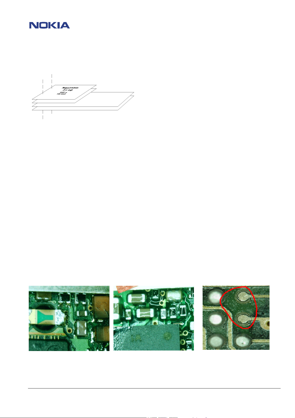
-Broken balls / underfill, µBGAs
All replaceable (not underfilled) µBGA components must be renewed after removing.
Reflow with uncontrolled hot air fan is strictly forbidden! µBGA must only be soldered with NMP approved µBGA rework
machines (e.g. Zevac / OK-Metcal / Martin) to get durable soldering joints.
After removing a µBGA, check soldering points; if necessary rework oxidated solderings (broken balls) carefully by
tinplating these areas with few flux and a hot soldering iron. Before placing a new component remove the tin and
clean the PCB, e.g. with help of solder wick and flux cleaner such as “Kontakt LR”.
Use only recommended flux type and an appropriate amount of it – avoid drowning the PCB in flux as this will result in
additional faults!
Also check underfilled parts for broken underfill material below.
In this case, carefully evaluate possible repair actions as the phone probably was exposed to strong mechanical stress.
“rework” done with uncontrolled hot air PCB drowned in flux Oxidated solderings
© NMP 2003
Checked by:
SCCE Training Group
Approved by:
CC Europe & Africa
Page 3
CONFIDENTIAL
3 (12)
Customer Care Europe Middle East & Africa NPM-6 / 5100 Repair Hints
SCCE Training Group Version 1.0 Approved
2003 Nokia Mobile Phones
19.05.2003
-PCB handling & cleaning
To avoid damages of PCB and/or components through electrostatic discharging, handle the module in ESD Area only
as shown on page 5 / “ESD protection requirements”.
When handling PCBs outside an ESD-bag always wear ESD-bracelets, which must be connected to earth bonding point.
Damage by electrostatic discharge often leads to a module not failing directly but in a short period of time!
For cleaning use only appropriate materials, do not use scratching or rubbing tools. Useful tools for cleaning are
flux cleaners such as “Kontakt LR” or “Electrolube FLU” in connection with ionized compressed air.
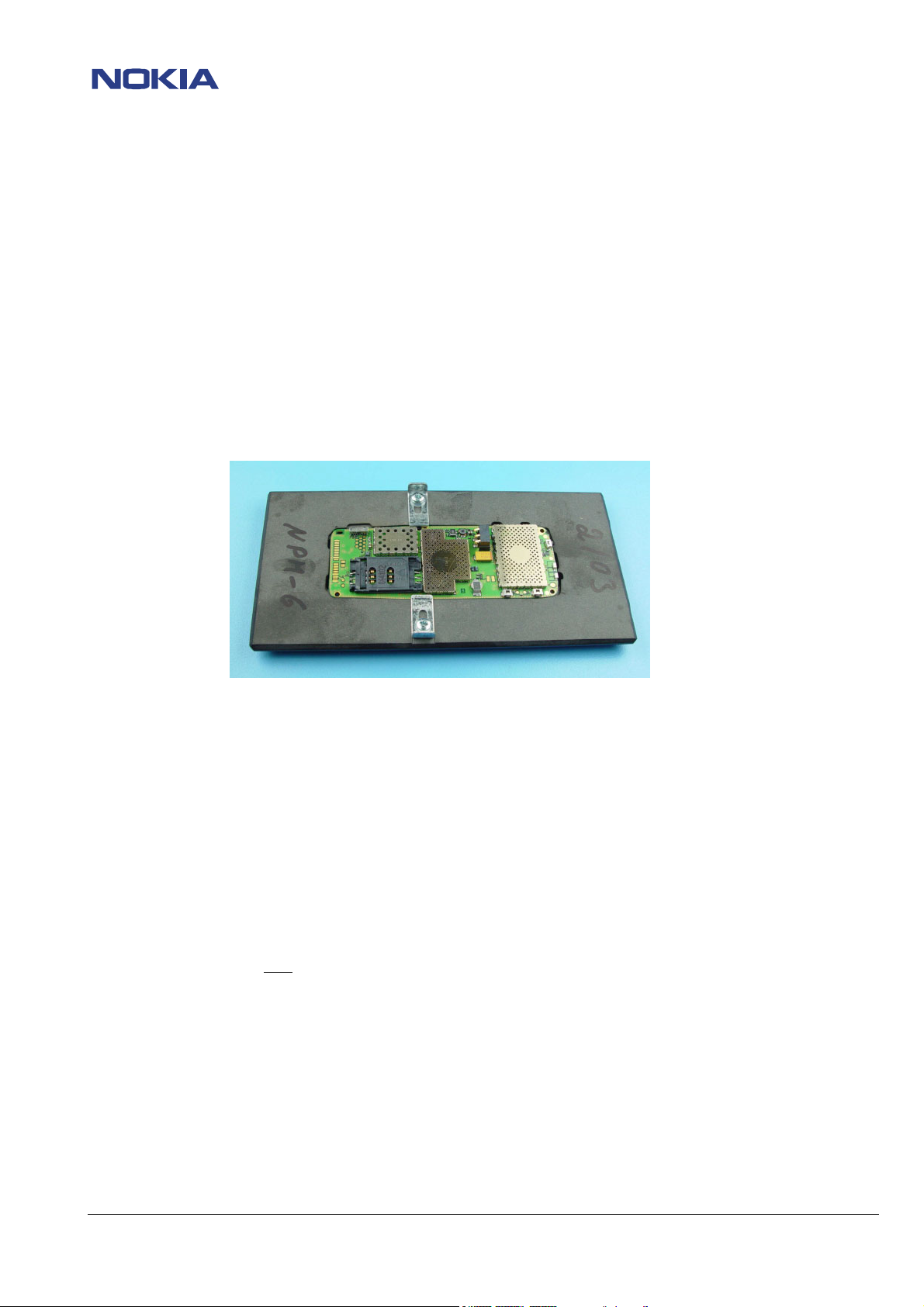
For shield disassembling or any other work on the PCB it is very important to place the PCB into the rework jig MJS-72
(NMP-code 0775325) to prevent damaging the LEDs – the pads, the LEDs are connected with to the PCB, are turn off by
applying only little pressure onto the PCB!!!
-Realign after repair
Characteristics of replacement parts may vary.
To prevent additional faults after repair (e.g. low standby time, losing network etc.) it is necessary to retune phone
values after repair, but never try to cover up a fault by adjusting the phone settings!
-Fault report in fault log (Phoenix)
It is very important to report all repaired failures in fault log after finishing the complete phone repair.
The report content should only
In this case the report content should contain the symptom code that is given from the customer
e.g “Does not switch on”(2101) and the faultcode“no fault found”(470).
If the symptom code from the customer is not the same as the observed symptom, always use the self-observed
symptom code.
contain the self-observed fault symptom, except “no fault found”.
© NMP 2003
Checked by:
SCCE Training Group
Approved by:
CC Europe & Africa
Page 4
CONFIDENTIAL
4 (12)
Customer Care Europe Middle East & Africa NPM-6 / 5100 Repair Hints
SCCE Training Group Version 1.0 Approved
2003 Nokia Mobile Phones
19.05.2003
-Shieldings, screw torques
To avoid RF-problems it is not allowed to reuse any shielding that once having been removed from shielding frame.
Always use new shieldings after successful repair! Also the C-Cover (9458479) can only be used twice!
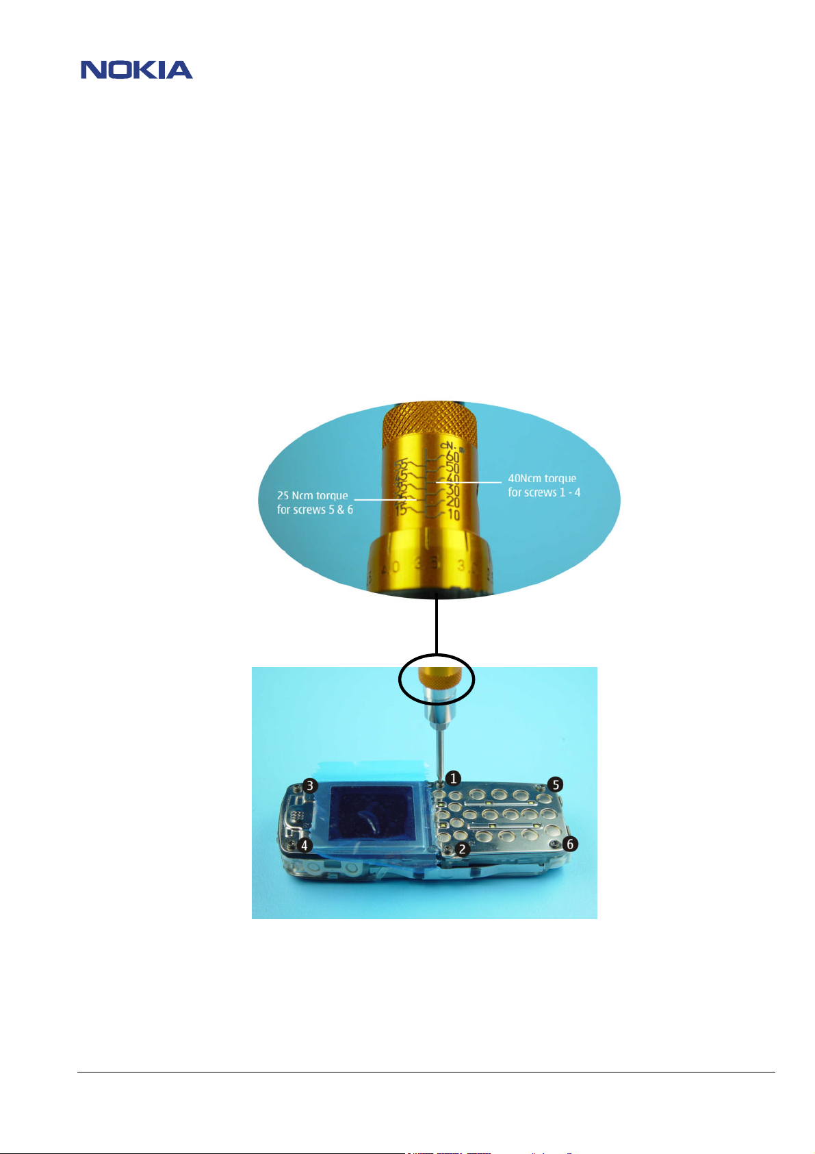
To assemble the phone after a succesfull repair it is necessary to use a T6 screwdriver with a torque range of minimum
40 Ncm. Suitable torque screwdrivers must be ordered locally. Refer to SB006 for more information.
The screwdriver torque must be adjusted to 40 Ncm for the screws 1, 2, 3 & 4.
For the screws 5&6 the screwdriver torque must be adjusted to 25 Ncm (see picture “Torque adjustment”).
“Torque adjustment”
“Assemble order”
Notice the tightening order to assemble the phone (from 1 to 6) as shown in the picture “Assemble order”!
To disassemble the phone proceed in reverse order (from 6 to 1) and use a T6 screwdriver without torque for this!
Note: All screws can be assembled only once. Always use new screws for assembling.
© NMP 2003
Checked by:
SCCE Training Group
Approved by:
CC Europe & Africa
Page 5

e
r
d
Customer Care Europe Middle East & Africa NPM-6 / 5100 Repair Hints
SCCE Training Group Version 1.0 Approved
2003 Nokia Mobile Phones
CONFIDENTIAL
19.05.2003
5 (12)
ESD PROTECTION REQUIREMENTS
Electrostatic discharge can easily damage the sensitiv
components of electronic products. Therefore, every Service Partne
has to take of at least some precautions, such as ESD restricte
area, floor, table, covering, chair(s), shoes, or arm wrist.
Please refer to the Partner Web site document
“Service Partner Requirements”
example of an epa area set-up
source: www.armeka.com
example of a workbench and testers
source: http://www.armekaengineering.com
example of a workbench set-up
source: www.warmbier.com
© NMP 2003
Checked by:
SCCE Training Group
Approved by:
CC Europe & Africa
Page 6

CONFIDENTIAL
6 (12)
Customer Care Europe Middle East & Africa NPM-6 / 5100 Repair Hints
SCCE Training Group Version 1.0 Approved
2003 Nokia Mobile Phones
19.05.2003
INTRODUCTION
IMPORTANT:
This document is intended for use by authorized NOKIA service centers only.
The purpose of this document is to provide some further service information for NOKIA 5100 phones.
It contains a lot of collected tips and hints to find faults and repair solutions easily.
It also will give support to inexperienced technicians.
Saving process time and improving the repair quality is the aim of this document.
It is built up based on fault symptoms (listed in "Contents") followed by detailed description for further analysis.
The document is to be used additionally to the service manual and other service information such as Service Bulletins.
For that reason it does not contain any circuit or schematic diagrams.
All measurements are made using following equipment:
Nokia repair SW: Phoenix version A7 2003.9.7.8
MCU SW: 3.02 for 5100
Nokia module jig: MJS – 49
Docking station: JBV-1
Docking Adapter: MJF-17
Digital multimeter: Fluke 73
Oscilloscope: Fluke PM 3380A/B
Spectrum Analyzer: Advantest R3131 with an analog probe
RF-Generator / GSM Tester: Rohde & Schwarz CMU 200
While every endeavour has been made to ensure the accuracy of this document, some errors may exist. If the reader
finds any errors, NOKIA should be notified in writing, using the following procedure:
Please state:
title of the document + issue number/date of publication.
page(s) and/or figure(s) in error.
Please send to: Nokia GmbH
Service & Competence Center Europe
Meesmannstr.103
D-44807 Bochum / Germany
Nokia GmbH
Email: training.sace@nokia.com
Copyright © Nokia Mobile Phones.
This material, including documentation and any related computer programs is protected by copyright, controlled by
Nokia Mobile Phones. All rights are reserved. Copying, including reproducing, modifying, storing, adapting or
translating any or all of this material requires the prior written consent of Nokia Mobile Phones. This material also
contains confidential information, which may not be disclosed to others without the prior written consent of Nokia
Mobile Phones.
© NMP 2003
Checked by:
SCCE Training Group
Approved by:
CC Europe & Africa
Page 7

CONFIDENTIAL
7 (12)
Customer Care Europe Middle East & Africa NPM-6 / 5100 Repair Hints
SCCE Training Group Version 1.0 Approved
2003 Nokia Mobile Phones
19.05.2003
Contents
PREFACE
CHAPTER 2
CHAPTER 3
Damaged adhesive gasket on system connector 8
Correct position of covering seal part 9
CHAPTER 4
“Phone switches off itself” 10
“No key & ringing tone” 10
“Constant buzzer tone” 10
CHAPTER 5
Defective flash component 11
CHAPTER 6
General 2
Introduction 5
Mechanical problems
Symptoms
Fault description
Change history 12
© NMP 2003
Checked by:
SCCE Training Group
Approved by:
CC Europe & Africa
Page 8

CONFIDENTIAL
8 (12)
Customer Care Europe Middle East & Africa NPM-6 / 5100 Repair Hints
SCCE Training Group Version 1.0 Approved
2003 Nokia Mobile Phones
19.05.2003
3. Mechanical Problems
Damaged adhesive gasket on system connector
Pre-check:
Be very carefully when disassembling and assembling the phone.
Especially check the adhesive gasket on system connector.
Fault description
Check on the left and the right side of system connector whether the adhesive gasket is intact (see figure “undamaged
adhesive gasket”).
If the adhesive gasket is damaged (see figure “damaged adhesive gasket”), the connector assy (5400257) must be
changed before assemble of the phone is done. See also the assembly video on Partner web site
Damaged adhesive gasket
Undamaged adhesive gasket
Note! The torque for screws (5&6) on the system connector is 25 Ncm.
See also chapter “General/ Shieldings, screw torques” on page 4!
!
© NMP 2003
Checked by:
SCCE Training Group
Approved by:
CC Europe & Africa
Page 9

CONFIDENTIAL
9 (12)
Customer Care Europe Middle East & Africa NPM-6 / 5100 Repair Hints
SCCE Training Group Version 1.0 Approved
2003 Nokia Mobile Phones
19.05.2003
Correct position of covering seal part
Pre-check:
Take care when disassembling and assembling the phone.
Especially check the covering seal part on C-Cover.
Fault description
Check if the covering seal part on the C-Cover has the correct position before assembling the phone, as shown in figure
“correct seal position”.
Phones, which are assembled with covering seal part as shown in figure “wrong seal position”, could even fail during
the flash update.
In this case the C-Cover assy (9458479) must always be changed, because it is not possible anymore to get the
necessary seal for the phone with the used seal part.
Wrong seal position Correct seal position
Note! The C-Cover can only be used twice!
The torque for screws 5&6 on the system connector is 25 Ncm, for the screws 1-4 the torque is 40 Ncm.
See also chapter “General/ Shieldings, screw torques” on page 4!
© NMP 2003
Checked by:
SCCE Training Group
Approved by:
CC Europe & Africa
Page 10

CONFIDENTIAL
10 (12)
Customer Care Europe Middle East & Africa NPM-6 / 5100 Repair Hints
SCCE Training Group Version 1.0 Approved
2003 Nokia Mobile Phones
19.05.2003
4. Symptoms
Phone switches off itself
Pre-check:
Switch the phone on and try to establish a test call with a tester, e.g CMU.
- If the phone switches off itself or/and no key & ringing tone is audible, follow the repair instructions:
o See “Defective flash component”/page 11
No key & ringing tone audible
Pre-check:
Switch the phone on and press any key.
The key tones must be audible every time (one short tone) a key is pressed.
Check also if ringing tone is audible. Notice that the key & ringing tones must be activated in the “profile” menu.
- If no key & ringing tone is audible, follow the repair instructions:
o See “Defective flash component”/page 11
Constant buzzer tone
Pre-check
Switch the phone on and press any key.
The key tones must be audible every time (one short tone) a key is pressed.
Notice that the key tone is activated in the “profile” menu.
- If only a constant buzzer tone is audible after pressing the key, follow the repair instructions:
o See “Defective flash component”/page 11
© NMP 2003
Checked by:
SCCE Training Group
Approved by:
CC Europe & Africa
Page 11

CONFIDENTIAL
11 (12)
Customer Care Europe Middle East & Africa NPM-6 / 5100 Repair Hints
SCCE Training Group Version 1.0 Approved
2003 Nokia Mobile Phones
19.05.2003
5. Fault description
Defevtive flash component
Symptoms: “Phone switches off itself”/page 10
“No key & ringing tone”/page 10
“Constant buzzer tone”/page 10
During certain weeks defective flash components (4341431) have been manufactured, causing the mentioned
symptoms.
Defective components can be identified by manufacturer´s work codes on top of the component, as shown on figure
“work code”. In the example “235” means: 2- for 2002 and 35- for week 35.
Defective flash components have a work code between 218 (18
They should be replaced by flash components (4341431) with work code 233 or later (see table)
Manufactorer´s work codes
code for defective flash code for replaceable flash
218 - 232 233 or later
Open the phone in described order (page 4) and check the flash component work code.
Note! Rewrite SIMlock and IMEI data by use of NOKIA SECURITY PASSWORD and tune the phone again, if the procedure is
permitted to you. (See General SB–037)
Work code
th
week 2002) and 232 (32
th
week 2002).
© NMP 2003
Checked by:
SCCE Training Group
Approved by:
CC Europe & Africa
Page 12

CONFIDENTIAL
12 (12)
Customer Care Europe Middle East & Africa NPM-6 / 5100 Repair Hints
SCCE Training Group Version 1.0 Approved
2003 Nokia Mobile Phones
19.05.2003
6 CHANGE HISTORY
Originator Status Version Date Comment
SCCE Training
Group
SCCE Training
Group
Draft
Approved
0.1
1.0
12.05.2002
19.05.2002
First draft version for the repair group
Approved version
© NMP 2003
Checked by:
SCCE Training Group
Approved by:
CC Europe & Africa
 Loading...