

Page 1

Customer Care Solutions
NPM-6/6X Series Transceivers
Disassembly and Assembly
Instructions
Issue 2 06/03 CopyrightNokia. All rights reserved
Page 2
NPM-6/6X
Disassembly and Assembly Instructions CCS Technical Documentation
Disassembling instructions ............................................................................................ 4
Exchange of system connector....................................................................................... 6
Exchange of battery connector...................................................................................... 8
Page 2 Copyright Nokia. All rights reserved Issue 2 06/03
Page 3
NPM-6/6X
CCS Technical Documentation Disassembly and Assembly Instructions
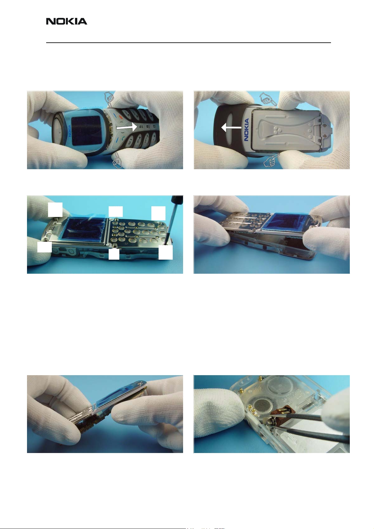
Disassembling instructions
Note! It is only allowed to reassemble C-Cover (phone) once. For second reassembling use of new C-Cover is mandatory! Use new screws in general.
Press the grip markings on both sides of the B-Shell and
remove B-Shell.
3
4
Tightening torques for screws (Note! Two tightening
torques!): -screws 1-4, use 40 Ncm
-screws 5-6, use 25 Ncm.
Tightening order for screws is from 1 to 6. When
tightening the screws 5 and 6 it is necessary to press
strongly the system connector against C-cover to avoid
sealing tape twisting in the system connector. If the
sealing tape twists with screwassembly it is not
waterproof anymore. Note! The screws can be assembled
only once.
1
2
5
6
To remove the A-Shell press Locking Springs as shown and
pull A-Shell from the unit.
Remove engine from C-Cover.
Separate the UI-Module from Radio Module carefully,
because of the board-to board-connector.
Use tweezers to remove Vibra Motor.
Issue 2 06/03 CopyrightNokia. All rights reserved Page 3
Page 4

NPM-6/6X
Disassembly and Assembly Instructions CCS Technical Documentation
Remove Earpiece. Note the guiding pin when assembling. Remove Keymat.
Page 4 Copyright Nokia. All rights reserved Issue 2 06/03
Page 5

NPM-6/6X
CCS Technical Documentation Disassembly and Assembly Instructions
Exchange of system connector
The System Connector is attached with double-sided
adhesive gasket to C-Cover. Also note the gasket on CCover.
Press again SRT-6 between C-Cover and System Connector
and remove System Connector.
Press SRT-6 between C-Cover and System Connector and
remove Battery Cover.
Remove System Connector.
To remove the remaining adhesive gasket use SRT-6 only.
Do not use sharp-edged tools for this procedure.
Remove protection foil from System Connector.
Issue 2 06/03 CopyrightNokia. All rights reserved Page 5
Page 6

NPM-6/6X
Disassembly and Assembly Instructions CCS Technical Documentation
Place System Connector to its guidance exactly. Now press connector to C-Cover firmly, while taking care
not to slip C-Cover on your table.
Page 6 Copyright Nokia. All rights reserved Issue 2 06/03
Page 7

NPM-6/6X
CCS Technical Documentation Disassembly and Assembly Instructions
Exchange of battery connector
These are the two soldered support angles. Use a side cutter to cut the support angles.
Push tweezers in outer openings of battery connector and
lift up the plastic cover.
Note that you need a soldering iron with higher
temperature when cleaning or soldering the grounding
pad.
Desolder all pins and clean the pads.
Tin one of pads to fix the connector before soldering the
following pins.
Issue 2 06/03 CopyrightNokia. All rights reserved Page 7
Page 8

NPM-6/6X
Disassembly and Assembly Instructions CCS Technical Documentation
Note location of connector pins and support angles to fit
them precisely.
Solder first support angle. When position is exact, solder
the other pins.
Page 8 Copyright Nokia. All rights reserved Issue 2 06/03
 Loading...