

Page 1

PAMS Technical Documentation
Chapter 6
NHN–5NT
SERVICE SOFTWARE
INSTRUCTIONS
Original 04/98
Copyright 1998 Nokia Mobile Phones. All rights reserved
Page 2

Service Software Instructions
PAMS
NHN–5NT
Amendment
Number
Technical Documentation
AMENDMENT RECORD SHEET
Date Inserted By Comments
Page 2
Original 04/98
Page 3

PAMS
Service Software Instructions
Technical Documentation
NHN–5NT Service Software Instructions
Contents
General Page 6. . . . . . . . . . . . . . . . . . . . . . . . . . . . . . . . . . . . . . . . . . . . . . . .
Minimum Required Servicing Equipment Page 6. . . . . . . . . . . . . . . . .
Mechanical Connections Page 7. . . . . . . . . . . . . . . . . . . . . . . . . . . . . .
Start Up Procedure Page 8. . . . . . . . . . . . . . . . . . . . . . . . . . . . . . . . . . .
Introduction to Service Software Package User Interface Page 8. .
Service Software/Hardware Environment Page 8. . . . . . . . . . . . . .
Service Software Environment Page 9. . . . . . . . . . . . . . . . . . . . . . .
Service Software Executables Page 9. . . . . . . . . . . . . . . . . . . . . . .
Command Line Parameters Page 10. . . . . . . . . . . . . . . . . . . . . . . . .
Common Properties of the User Interface Page 11. . . . . . . . . . . . . . . . . .
Login Dialog Page 11. . . . . . . . . . . . . . . . . . . . . . . . . . . . . . . . . . . . . . . . .
Main Window Page 13. . . . . . . . . . . . . . . . . . . . . . . . . . . . . . . . . . . . . . . .
Menu Bar Page 14. . . . . . . . . . . . . . . . . . . . . . . . . . . . . . . . . . . . . . . . . . . .
Product Page 16. . . . . . . . . . . . . . . . . . . . . . . . . . . . . . . . . . . . . . . . . . .
Configure Page 16. . . . . . . . . . . . . . . . . . . . . . . . . . . . . . . . . . . . . . . . .
Tuning Page 17. . . . . . . . . . . . . . . . . . . . . . . . . . . . . . . . . . . . . . . . . . . .
Testing Page 18. . . . . . . . . . . . . . . . . . . . . . . . . . . . . . . . . . . . . . . . . . . .
Dealer Page 19. . . . . . . . . . . . . . . . . . . . . . . . . . . . . . . . . . . . . . . . . . . .
Help Page 19. . . . . . . . . . . . . . . . . . . . . . . . . . . . . . . . . . . . . . . . . . . . . .
Mouse Cursors Page 19. . . . . . . . . . . . . . . . . . . . . . . . . . . . . . . . . . . . . . .
Reserved Keys Page 20. . . . . . . . . . . . . . . . . . . . . . . . . . . . . . . . . . . . . . .
Short Cut Function Keys Page 20. . . . . . . . . . . . . . . . . . . . . . . . . . . .
Alt Hot Keys Page 20. . . . . . . . . . . . . . . . . . . . . . . . . . . . . . . . . . . . . . .
Ctrl Hot Keys Page 20. . . . . . . . . . . . . . . . . . . . . . . . . . . . . . . . . . . . . .
Shift Hot Keys Page 20. . . . . . . . . . . . . . . . . . . . . . . . . . . . . . . . . . . . .
Key Strokes Page 21. . . . . . . . . . . . . . . . . . . . . . . . . . . . . . . . . . . . . . .
Help Functions Page 22. . . . . . . . . . . . . . . . . . . . . . . . . . . . . . . . . . . . . . .
Dialog boxes Page 22. . . . . . . . . . . . . . . . . . . . . . . . . . . . . . . . . . . . . . . . .
Common Dialog boxes Page 23. . . . . . . . . . . . . . . . . . . . . . . . . . . . . .
Custom Dialog boxes Page 24. . . . . . . . . . . . . . . . . . . . . . . . . . . . . . .
Buttons Page 24. . . . . . . . . . . . . . . . . . . . . . . . . . . . . . . . . . . . . . . . . . . . .
Reporting Status Page 25. . . . . . . . . . . . . . . . . . . . . . . . . . . . . . . . . . . . .
NHN–5NT
NHN–5N Specific Features Page 26. . . . . . . . . . . . . . . . . . . . . . . . . . . . . . .
Menu Bar Page 26. . . . . . . . . . . . . . . . . . . . . . . . . . . . . . . . . . . . . . . . . . . .
Product Menu Page 26. . . . . . . . . . . . . . . . . . . . . . . . . . . . . . . . . . . . . . . .
New command Page 26. . . . . . . . . . . . . . . . . . . . . . . . . . . . . . . . . . . . .
Open... command Page 26. . . . . . . . . . . . . . . . . . . . . . . . . . . . . . . . . .
Close command Page 26. . . . . . . . . . . . . . . . . . . . . . . . . . . . . . . . . . .
Initialize command Page 27. . . . . . . . . . . . . . . . . . . . . . . . . . . . . . . . .
Faultlog Page 27. . . . . . . . . . . . . . . . . . . . . . . . . . . . . . . . . . . . . . . . . . .
Original 04/98
Page 3
Page 4

Service Software Instructions
PAMS
NHN–5NT
Exit command Page 27. . . . . . . . . . . . . . . . . . . . . . . . . . . . . . . . . . . . .
Configure Menu Page 28. . . . . . . . . . . . . . . . . . . . . . . . . . . . . . . . . . . . . .
Options... command Page 28. . . . . . . . . . . . . . . . . . . . . . . . . . . . . . . .
Directories... command Page 28. . . . . . . . . . . . . . . . . . . . . . . . . . . . .
Faultlog... command Page 28. . . . . . . . . . . . . . . . . . . . . . . . . . . . . . . .
RF Controls Page 29. . . . . . . . . . . . . . . . . . . . . . . . . . . . . . . . . . . . . . .
Tuning Menu Page 30. . . . . . . . . . . . . . . . . . . . . . . . . . . . . . . . . . . . . . . . .
Initialize Local Mode Page 31. . . . . . . . . . . . . . . . . . . . . . . . . . . . . . . .
AFC Frequency Page 32. . . . . . . . . . . . . . . . . . . . . . . . . . . . . . . . . . . .
AFC Frequency Limits Page 33. . . . . . . . . . . . . . . . . . . . . . . . . . . . . .
RSSI and AGC Page 34. . . . . . . . . . . . . . . . . . . . . . . . . . . . . . . . . . . .
Deviation Page 37. . . . . . . . . . . . . . . . . . . . . . . . . . . . . . . . . . . . . . . . . .
TX Output Power Page 38. . . . . . . . . . . . . . . . . . . . . . . . . . . . . . . . . . .
Battery Voltage Tuning Page 39. . . . . . . . . . . . . . . . . . . . . . . . . . . . . .
Charger Voltage Tuning Page 40. . . . . . . . . . . . . . . . . . . . . . . . . . . . .
LCD Contrast Page 41. . . . . . . . . . . . . . . . . . . . . . . . . . . . . . . . . . . . . .
Show Tuning Values Page 42. . . . . . . . . . . . . . . . . . . . . . . . . . . . . . . .
Testing Menu Page 43. . . . . . . . . . . . . . . . . . . . . . . . . . . . . . . . . . . . . . . .
Basic Settings Page 43. . . . . . . . . . . . . . . . . . . . . . . . . . . . . . . . . . . . .
ADC Readings Page 45. . . . . . . . . . . . . . . . . . . . . . . . . . . . . . . . . . . . .
Audio Control Page 46. . . . . . . . . . . . . . . . . . . . . . . . . . . . . . . . . . . . . .
Special Settings Page 48. . . . . . . . . . . . . . . . . . . . . . . . . . . . . . . . . . . .
FFSK Data Sending Control Page 50. . . . . . . . . . . . . . . . . . . . . . . . .
Single Tone and DTMF Control Page 52. . . . . . . . . . . . . . . . . . . . . .
Dealer Menu Page 53. . . . . . . . . . . . . . . . . . . . . . . . . . . . . . . . . . . . . . . . .
Subscriber Data Page 53. . . . . . . . . . . . . . . . . . . . . . . . . . . . . . . . . . . .
Short Code Memory Page 56. . . . . . . . . . . . . . . . . . . . . . . . . . . . . . . .
Warranty Information Page 57. . . . . . . . . . . . . . . . . . . . . . . . . . . . . . .
Country Codes Page 58. . . . . . . . . . . . . . . . . . . . . . . . . . . . . . . . . . . . .
SMS Information Page 60. . . . . . . . . . . . . . . . . . . . . . . . . . . . . . . . . . .
Help Menu Page 61. . . . . . . . . . . . . . . . . . . . . . . . . . . . . . . . . . . . . . . . . . .
Index Page 61. . . . . . . . . . . . . . . . . . . . . . . . . . . . . . . . . . . . . . . . . . . . .
General Help Page 61. . . . . . . . . . . . . . . . . . . . . . . . . . . . . . . . . . . . . .
Using Help Page 61. . . . . . . . . . . . . . . . . . . . . . . . . . . . . . . . . . . . . . . .
About WinTesla Page 61. . . . . . . . . . . . . . . . . . . . . . . . . . . . . . . . . . . .
Required Equipment Page 62. . . . . . . . . . . . . . . . . . . . . . . . . . . . . . . . . .
Technical Documentation
Tuning Instructions Page 63. . . . . . . . . . . . . . . . . . . . . . . . . . . . . . . . . . . . . .
Equipment setup Page 63. . . . . . . . . . . . . . . . . . . . . . . . . . . . . . . . . . . . .
Equipment Setup Page 64. . . . . . . . . . . . . . . . . . . . . . . . . . . . . . . . . . . . .
Equipment Setup for Tuning a Phone without Removing Covers Page 64
Starting the Program Page 65. . . . . . . . . . . . . . . . . . . . . . . . . . . . . . . . . .
Manual Tuning Steps Page 65. . . . . . . . . . . . . . . . . . . . . . . . . . . . . . . . .
General Page 65. . . . . . . . . . . . . . . . . . . . . . . . . . . . . . . . . . . . . . . . . . .
Tunings menu Page 66. . . . . . . . . . . . . . . . . . . . . . . . . . . . . . . . . . . . . . . .
Page 4
Original 04/98
Page 5

PAMS
Service Software Instructions
Technical Documentation
1 – AFC Tuning Page 66. . . . . . . . . . . . . . . . . . . . . . . . . . . . . . . . . . . .
2 – AFC Limits Tuning Page 66. . . . . . . . . . . . . . . . . . . . . . . . . . . . . .
3 – RSSI and AGC Tuning Page 66. . . . . . . . . . . . . . . . . . . . . . . . . . .
4 – Deviation Tuning Page 67. . . . . . . . . . . . . . . . . . . . . . . . . . . . . . . .
FFSK Deviation Tuning Page 67. . . . . . . . . . . . . . . . . . . . . . . . . . .
Nominal Deviation Tuning Page 67. . . . . . . . . . . . . . . . . . . . . . . . .
Maximum Deviation Tuning Page 68. . . . . . . . . . . . . . . . . . . . . . .
Phi Signal Deviation Tuning Page 68. . . . . . . . . . . . . . . . . . . . . . .
5 – TX Output Power Tuning Page 68. . . . . . . . . . . . . . . . . . . . . . . . .
6 – Battery Voltage Tuning Page 68. . . . . . . . . . . . . . . . . . . . . . . . . .
7 – Charger Voltage Tuning Page 69. . . . . . . . . . . . . . . . . . . . . . . . . .
8 – LCD Contrast Tuning Page 69. . . . . . . . . . . . . . . . . . . . . . . . . . . .
9 – Show Tuning Values Page 69. . . . . . . . . . . . . . . . . . . . . . . . . . . .
Appendix 1, Vocabulary Page 70. . . . . . . . . . . . . . . . . . . . . . . . . . . . . . .
NHN–5NT
Original 04/98
Page 5
Page 6

Service Software Instructions
PAMS
NHN–5NT
General
The NHN5N Service Software is specially designed to facilitate the servicing of
sixth generation cellular NMT telephones. The software can be used to control
the phone according to the user’s requirements merely by entering commands
via the keyboard / mouse of a PC connected to the phone.
After Sales will notify service personnel about future upgrades via Technical
Bulletins. Software upgrades will be available from your local NMP outlet.
Minimum Required Servicing Equipment
–Computer: Intel 386/33 MHz or compatible with one unused serial port
(COM1 or COM2*), one parallel port (LPT1), hard disk recommended.
–Operating System: DOS Version 5 & Microsoft Windows 3.11 or later
–Display: VGA based display
–Service Software program: for 3.5” disk (product code: 077 4083)
–Software Protection Key PKD–1 (product code 0750018)
Technical Documentation
–M2BUS interface cable DAU–4S (product code 0730057)
*)
Note:
A number of PC’s of an older generation use the Intel, National Semiconductor,
or United Microelectronics IC 8250 as the serial port UART. This is a compara-
tively inefficient circuit for current purposes and does not necessarily support
the M2BUS adapter at 9600 baud. The newer UART’s NS16450 and
NS16550AF of National Semiconductor offer solutions for these problems.
Page 6
Original 04/98
Page 7
PAMS
Service Software Instructions
Technical Documentation
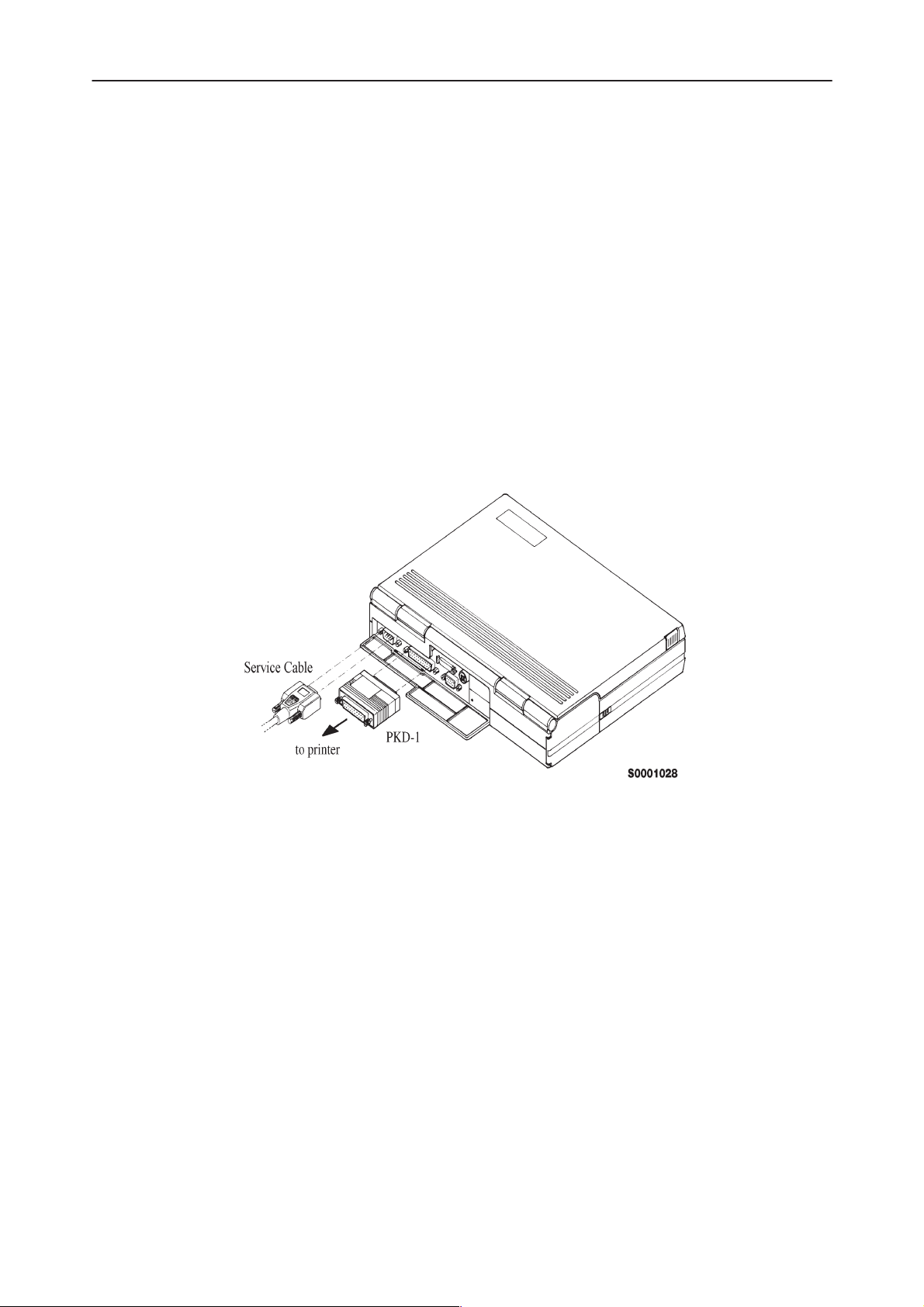
Mechanical Connections
Caution: Ensure that you have switched off the PC and the printer before
making connections !Caution:Do not connect the PKD–1 to the serial port. This
could damage the PKD–1 !
The software controls the phone via a separate adapter connected to the serial
port of the PC and to the telephone’s M2BUS (DAU–4S and XCM–1).
Attach the protection key PKD–1 to parallel port one (25–pin female D–connec-
tor) of the PC. When connecting the PKD–1 to the parallel port be sure that you
insert the PC end of the PKD–1 to the PC (male side). If you use a printer on
parallel port one, place the PKD–1 between the PC and your printer cable.
The PKD–1 should not effect devices working with it. If some errors occur (er-
rors in printing are possible) please try printing without the PKD–1. If printing is
OK without the PKD–1 please contact your dealer. We will offer you a new
PKD–1 in exchange for your old one.
NHN–5NT
Original 04/98
Page 7
Page 8
Service Software Instructions
PAMS
NHN–5NT
Technical Documentation
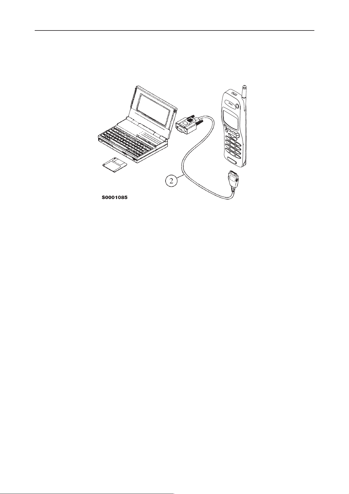
Attach one end of the M2BUS interface cable, DAU–4S (2), to the PC serial
port and the other end to the bottom connector of the phone.
Start Up Procedure
Start the phone by pressing the power–on button of the handset. Switch PC
power on.
To installing software, proceed as follows:
1. Insert Service Software disk into drive A of your PC
2. Start Windows: type
3. Start Installing program: select
4. Follow Installation Software instructions
WIN
and press
File –> Run
menu, then type
OK
press
button
Enter
from Program Manager
A:INSTALL
and
Introduction to Service Software Package User Interface
This chapter gives a short description of the Service Software properties.
Service Software/Hardware Environment
Page 8
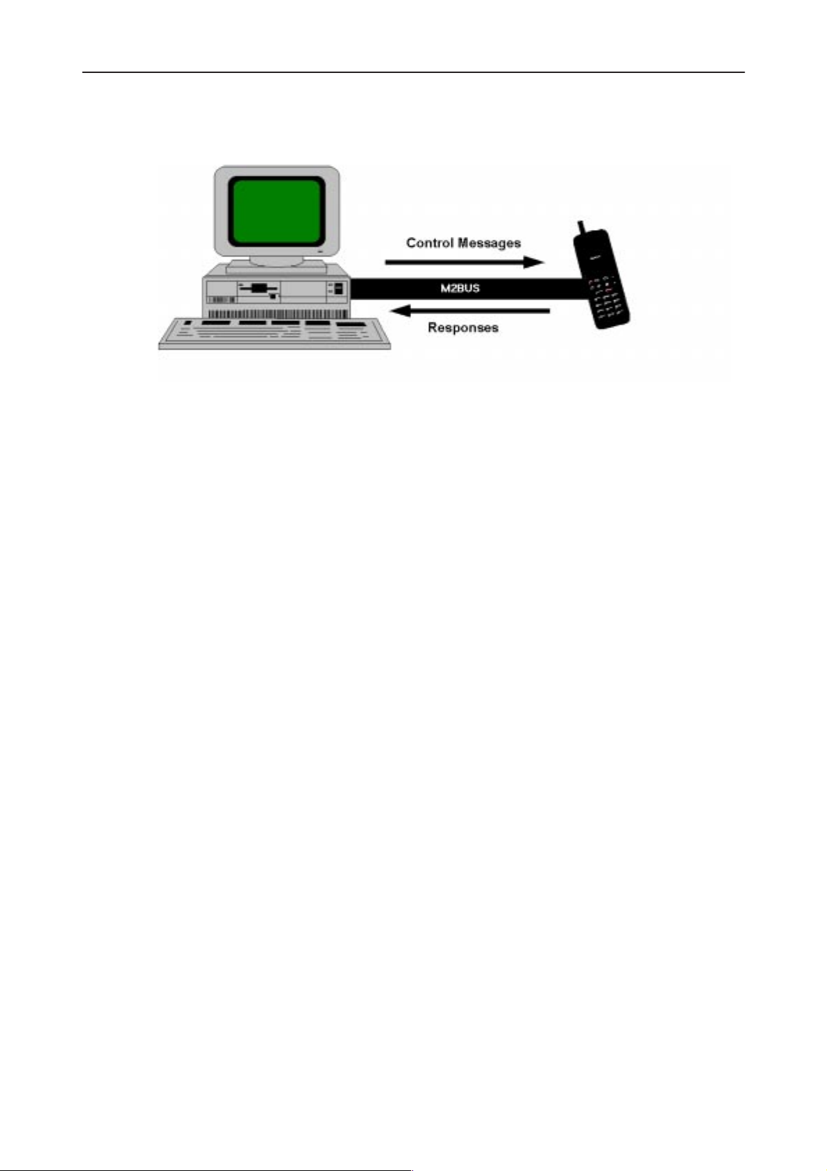
To run the Service Software, a parallel port software protection device (PKD–1)
has to be connected. The user can use the Service Software functions for test-
ing all supported Phone Types. The functions send messages from the PC to
the phone, receives results and show them on the PC display. The messages
are sent via a low level NMP proprietary bus protocol. An example bus is an
Original 04/98
Page 9
PAMS
Service Software Instructions
Technical Documentation
M2BUS interface, which needs M2BUS adapter (DAU–2) connected to the PC
RS–232 port and special M2BUS cable.
The recommended minimum hardware standard to run the Service Software
package is any computer which is 386 33Mhz or greater with at least 4 MB of
memory and VGA type display (640x480). This assumes that only the Service
Software package is active, i.e. other Windows packages are not running in the
background.
NHN–5NT
Note: if the Service Software is to be run on a laptop, the power saving feature
MUST be switched off.
Service Software Environment
Service Software user interface is intended for Microsoft Windows 3.11 environ-
ment running in enhanced mode. For those who are familiar with Windows en-
vironment this application will be easy to use. Detailed information about Win-
dows and application usage can be found from Ref 3– Microsoft Windows
Version 3.11 Users Guide chapter one (Windows Basics) and chapter two (Ap-
plication Basics).
As an ordinary Windows application, the main idea in the user interface is that
selections are made with menus, push buttons and shortcut keys. Selections
can be done by using keyboard and/or mouse. When messages from phone
are received, they cause display updating in special display windows. There is
always a status bar displayed at the bottom of the main window which contains
information about current actions.
Service Software Executables
Only one executable is needed – WinTesla.
For NHN–5NT, there are two DLL’s:
– Functionality DLL is NHN5.DLL
– User Interface DLL is NHN5EN.DLL
Original 04/98
Page 9
Page 10

Service Software Instructions
PAMS
NHN–5NT
Command Line Parameters
There are NO command line parameters.
Technical Documentation
Page 10
Original 04/98
Page 11
PAMS
Service Software Instructions
Technical Documentation
Common Properties of the User Interface
This chapter describes how the User Interface CLF must appear to the user.
The User Interface MUST be capable of being driven without the use of a
mouse, as the service engineer rarely has space on the bench to use a mouse.
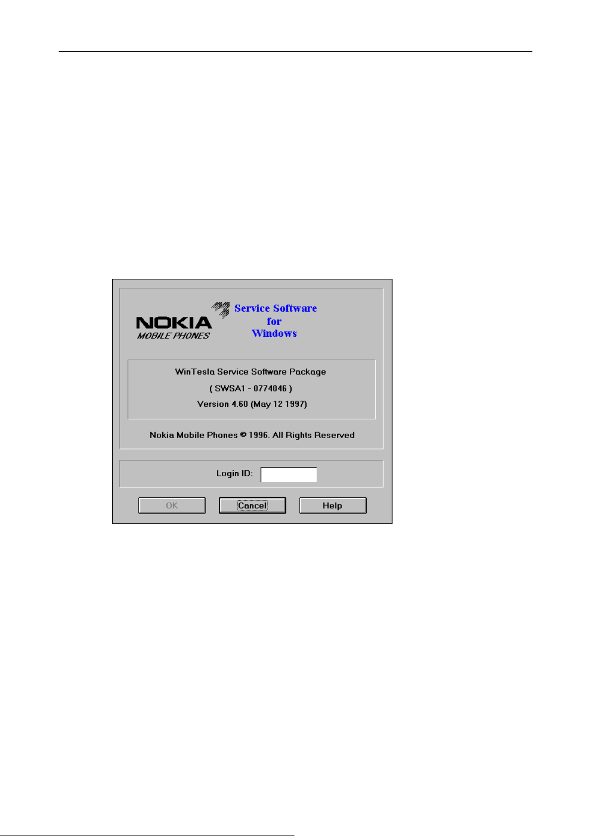
Login Dialog
When the Service Software application is invoked, by checking on the Service
Software icon, the Login dialog box will be displayed on the screen.
NHN–5NT
Nokia logo and application name bitmap (–)
Application version static text (–)
Copyright notice static text (–)
Login Box edit box (–)
Original 04/98
Displays Nokia logo and name of the application.
Contains the name and version of the application.
Copyright is informed as:
“Nokia Mobile Phones (c) 1997. All Rights Reserved”.
The user Login ID edit box, where the user enters his faultlog user
name.
Page 11
Page 12

Service Software Instructions
PAMS
NHN–5NT
Technical Documentation
OK button (default key)
The user name is stored in memory and the dialog box is closed.
When the dialog box is closed, the application starts.
Cancel button (ESC)
The Dialog box is closed and application is started, but the Faultlog
feature is disabled.
Help button (F1)
Activates the Windows Help application and displays context sensitive Help.
Page 12
Original 04/98
Page 13
PAMS
Service Software Instructions
Technical Documentation
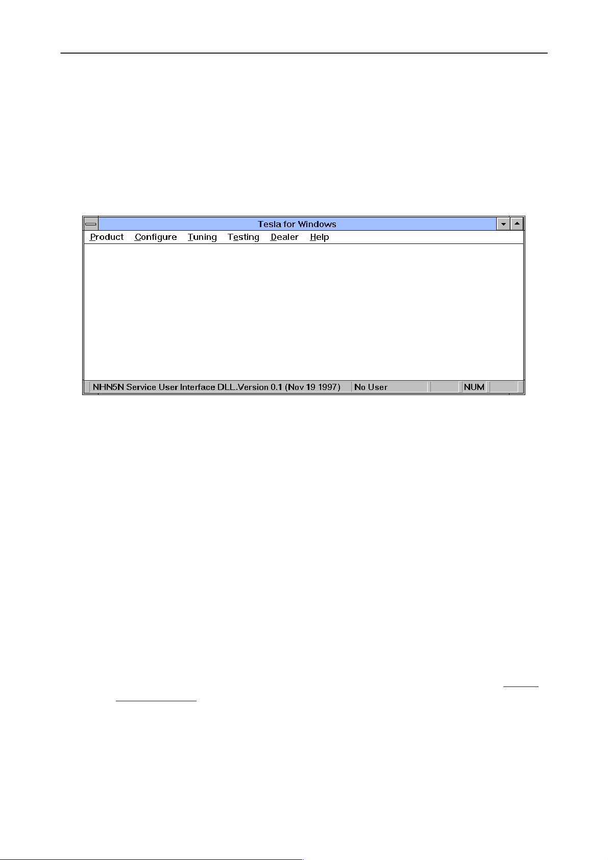
Main Window
The application supports a
service software interface will present a
pearance.
Note: MDI is to allow for future expansion, e.g. R&D features.
Multiple Document Interface (MDI).
Single Document Interface (SDI)
NHN–5NT
However, the
ap-
Title bar
title bar
The
A title bar contains the following elements:
The properties of these elements and their usage is described in Ref 3– Micro-
soft Windows Version 3.1 Users Guide chapter one (Windows Basics) and
chapter two (Application Basics).
Menu bar
menu bar
The
The menu bar is a dynamic element and is dependent on the dongle type fitted,
and whether a phone is connected. Underlined characters in menu names and
options indicates that the menu selection can be done by pressing
lined character
key ( or
case, selection is done by pressing
is located at the top of the window.
• Application Control–menu button
• Maximise button
• Minimise button
• Name of the application
• Restore button
is below the title bar and contains all available menu selections.
Alt+ under-
. Options can also be selected by activating menu bar with
F10
key ) and using arrow–keys to highlight the desired menu. In that
Enter
.
Alt
–
Original 04/98
Page 13
Page 14

Service Software Instructions
PAMS
NHN–5NT
Technical Documentation
Menus can also be selected by using the mouse as described in Ref 3–Micro-
soft Windows Version 3.11 Users Guide
Status bar
status bar
The
The status bar contains information about the menu selections and events.
The left area of the status bar describes the actions of menu items as the user
uses the arrow keys to navigate through menus.
The status bar texts are explained in detailed in each of command’s descrip-
tion.
The right areas of the status bar indicate which of the following keys are
latched down:
Indicator Description
USER Entered Login ID.
is displayed at the bottom of the Service Software main window.
Menu Bar
CAP The Caps Lock key is latched down.
NUM The Num Lock key is latched down.
SCRL The Scroll Lock key is latched down.
Tool bar
The
tool bar
document.
The Service Software package will have two menu bar configurations. The first,
is an abbreviated version that contains the minimum number of menus that al-
lows package configurations when a phone is NOT connected. The second is
described below:
The menu bar MUST only contain the follow menus for the Service Software
package when a phone is connected:
is NOT defined and will not be implemented until specified by this
Page 14
– P
roduct*
onfigure*
– C
– T
uning
– Te
sting
Original 04/98
Page 15

PAMS
Service Software Instructions
Technical Documentation
– D
ealer
elp*
– H
* – always displayed, even if no phone is connected.
A menu is broken down into sections that are indicated with menu separators.
Each sections identifies a logical difference from itself and other sections, i.e.
between transmitter and receiver. Any items that are required to be added to a
menu lists will be added on the bottom of the appropriate menu section list. If a
new item is to be added which is common to two or more phone types, then
that menu item will become a common menu item.
The menu lists will use the Microsoft [...] symbol after an item name to indicate
that selecting that item will NOT initiate an operation immediately, i.e. a dialog
box will be displayed for the user to select options or type in data and press the
OK button before the operation is performed.
NHN–5NT
Original 04/98
Page 15
Page 16
Service Software Instructions
PAMS
NHN–5NT
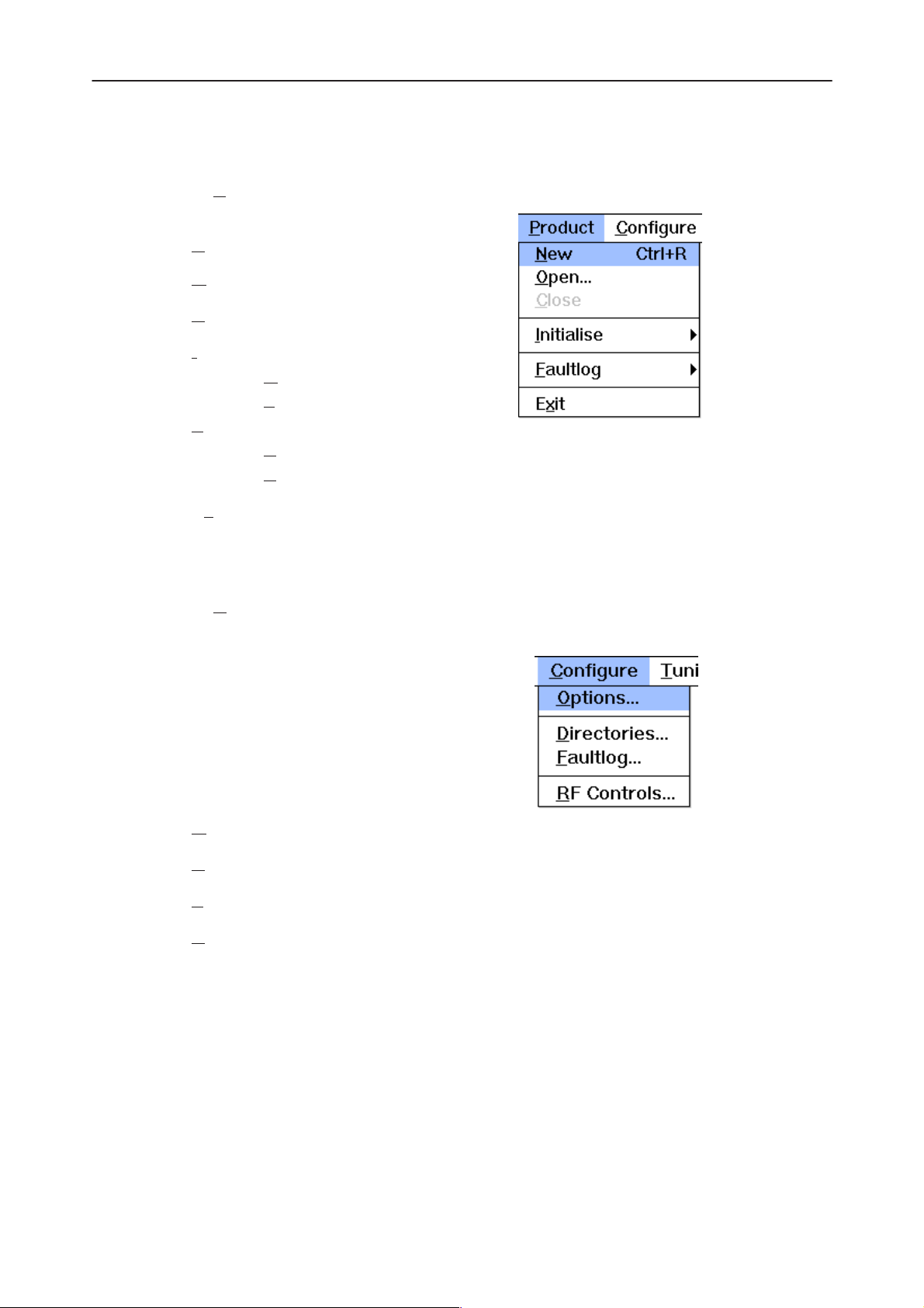
Product
The P
– New Ctrl+R
– O
– C
– I
– F
– Ex
roduct menu contains the following menu items:
pen...
lose
nitialize
N
ormal Mode F5
ocal Mode Shift+F5
L
aultlog
ctivate Faultlog... F9
A
E
dit Faultlog...
it Alt+F4
Technical Documentation
Configure
The Configure menu contains the following menu items:
– Options...
– D
irectories...
aultlog...
– F
– R
F Controls...
Page 16
Original 04/98
Page 17
PAMS
Service Software Instructions
Technical Documentation
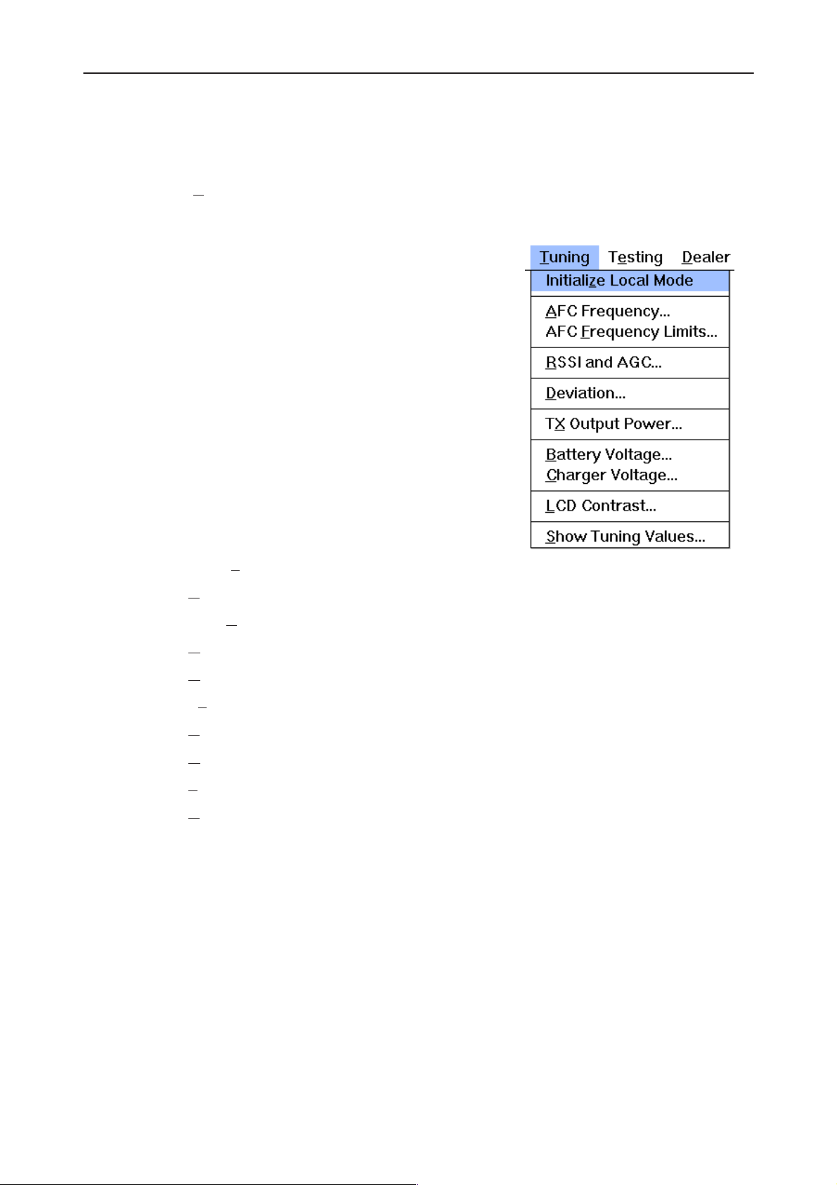
Tuning
The Tuning menu contains the following menu menu items:
NHN–5NT
– Initialize Local Mode
– A
FC Frequency...
– AFC F
– R
– D
– Tx
– B
– C
– L
– S
requency Limits...
SSI and AGC...
eviation...
Output Power...
attery Voltage...
harger Voltage...
CD Contrast...
how Tuning Values...
Original 04/98
Page 17
Page 18

Service Software Instructions
PAMS
NHN–5NT
Testing
The Testing menu contains the following menu items:
– Basic Settings...
DC Readings...
– A
Technical Documentation
– Audio C
pecial Settings...
– S
– F
FSK Data Sending Control...
– Single T
Additional menu items may be added within the sections according to the
phone type being tested.
Where a menu item consists of more than one test, a pop–up menu may be
added to identify the appropriate sub–tests.
ontrol
one and DTMF Control...
Page 18
Original 04/98
Page 19
PAMS
Service Software Instructions
Technical Documentation
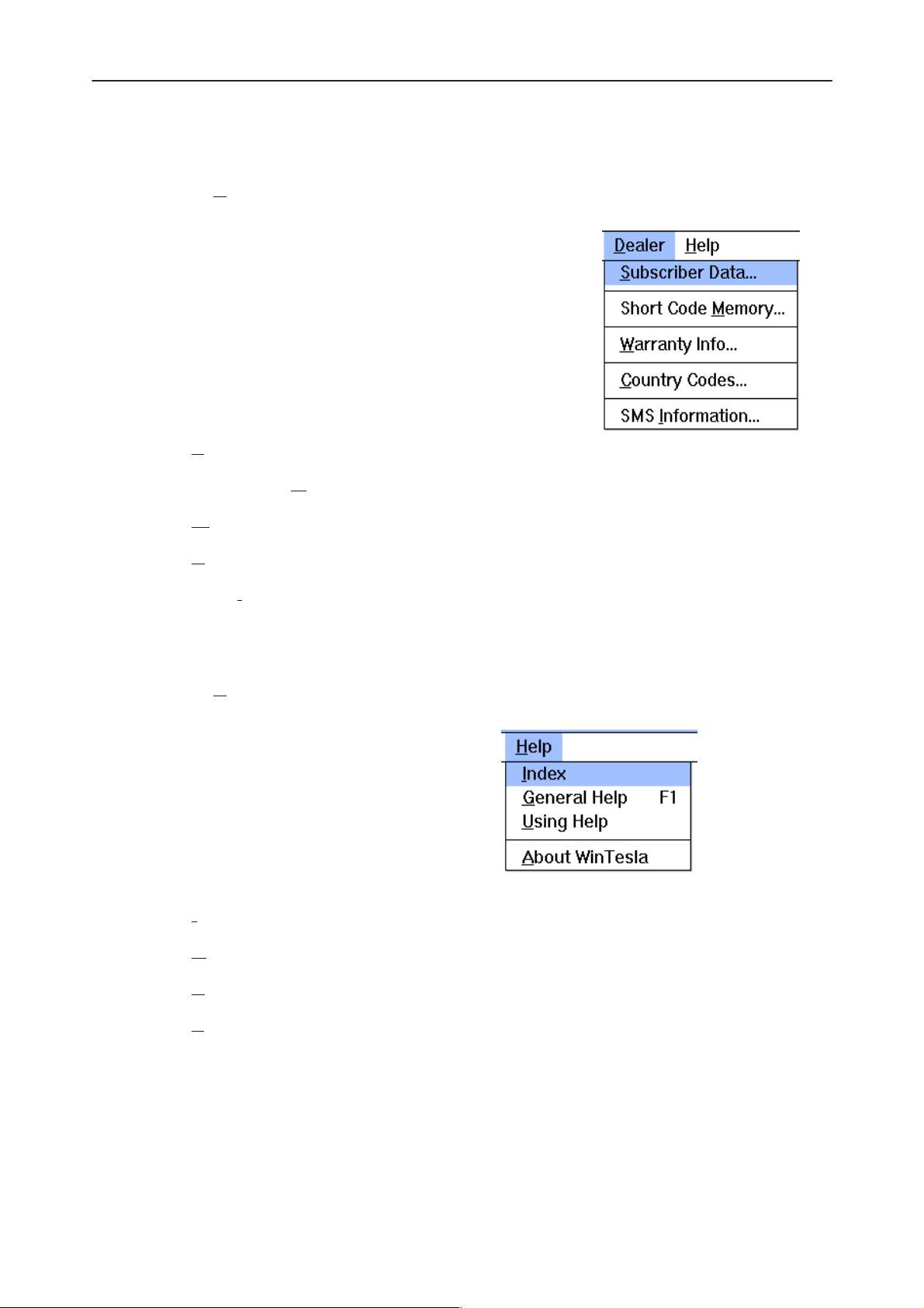
Dealer
The D
– Subscriber Data...
– Short Code M
– W
ealer menu contains the following menu items:
arranty Info...
NHN–5NT
emory...
Help
– C
ountry Codes...
– SMS I
The H
– Index
– G
– U
nformation...
elp menu contains the following menu items:
eneral Help
sing Help
bout WinTesla
– A
Mouse Cursors
The standards Windows pointer will be used as the mouse cursor.
Original 04/98
Page 19
Page 20

Service Software Instructions
PAMS
NHN–5NT
During time consuming tasks e.g. communication to phone, an hour glass will
be shown informing the user that a task is in progress. The application uses the
hour glass cursor to inform user that the application has taken the control and
any actions from user will be ignored.
When a function is initiated, the hour glass will be displayed and when the function has finished the mouse pointer will return to normal.
Reserved Keys
The following Hot keys and Short Cut keys are reserved either as Microsoft
standard keys or as part of the Common Look and Feel specified by this document.
Short Cut Function Keys
F1 Context Sensitive Help Microsoft
F5 Normal Mode NMP
Technical Documentation
Shift+F5 Local Mode NMP
F9 Activate Faultlog NMP
F10 Goto Menu Bar Microsoft
Ctrl+F4 Close Active Window Microsoft
Alt Hot Keys
Key Description Defined by
Alt+F4 Exit Active Application Microsoft
Alt+H Help Microsoft
Ctrl Hot Keys
Key Description Defined by
Ctrl+N F
Ctrl+O F
Ctrl+P F
Ctrl+R P
ile – New Microsoft
ile – Open Microsoft
ile – Print Microsoft
roduct – New NMP
Shift Hot Keys
Key Description Defined by
Shift+F5 Local Mode NMP
Page 20
Original 04/98
Page 21

PAMS
Service Software Instructions
Technical Documentation
Key Strokes
Key Description Defined by
Alt+P P
Alt+P, N N
Alt+P, O O
Alt+P, C C
Alt+P, I I
Alt+P, I, N N
Alt+P, I, L L
Alt+P, F F
Alt+P, F, A A
Alt+P, F, E E
Alt+P, X Ex
Alt+C C
NHN–5NT
roduct Menu NMP
ew NMP
pen NMP
lose NMP
nitialize Pop–up NMP
ormal Mode NMP
ocal Mode NMP
aultlog Pop–up NMP
ctivate Faultlog NMP
dit Faultlog NMP
it Application NMP
onfigure NMP
Alt+C, O O
Alt+C, D D
Alt+C, F F
Alt+C, R R
Alt+T T
Alt+T, Z Initializ
Alt+T, A A
Alt+T, F AFC F
Alt+T, R R
Alt+T, D D
Alt+T, X Tx
Alt+T, B B
Alt+T, C C
Alt+T, L L
Alt+T, S S
Alt+E Te
ptions NMP
irectories NMP
aultlog NMP
F Controls NMP
uning Menu NMP
FC Frequency NMP
SSI and AGC NMP
eviation NMP
Output Power NMP
attery NMP
harger NMP
CD Contrast NMP
how Tuning Values NMP
sting Menu NMP
e Local Mode NMP
requency Limits NMP
Alt+E, B B
Alt+E, A A
Alt+E, C Audio C
Alt+E, S S
Alt+E, F F
Original 04/98
asic Settings NMP
DC Readings NMP
ontrol NMP
pecial Settings NMP
FSK NMP
Page 21
Page 22

Service Software Instructions
PAMS
NHN–5NT
Alt+E, T Single T
Alt+D D
Alt+D, S S
Alt+D, M Short Code M
Alt+D, W W
Alt+D, C C
Alt+D, I SMS I
Alt+H H
Alt+H, I I
Alt+H, G G
Alt+H, U U
Alt+H, A A
Help Functions
Technical Documentation
one NMP
ealer Menu NMP
ubscriber Data NMP
emory NMP
arranty Info NMP
ountry Codes NMP
nformation NMP
elp Menu Microsoft
ndex Microsoft
eneral Help Microsoft
sing Help Microsoft
bout WinTesla Microsoft
The Help User Interface will be the standard Windows help tool called WinHelp.
The context sensitive help is activated with F1–key. Help contains also Using
Help which describes how to use help facility. Refer to the Windows manual for
detailed description on the Windows Help.
Dialog boxes
The Service Software application uses many different dialog boxes. Dialog
boxes are used to display data and prompt the user for input.
Dialog boxes are opened from menus or with shortcut keys. Dialog boxes have
different properties but some features are common.
All service dialog boxes must be modal, that is, the user will not be able to start
another operation without first closing the present dialog box.
All dialog boxes will contain the following entities:
– Help button
– Title bar
Page 22
– At least one button other than Help
– Application Control–menu Button
Original 04/98
Page 23

PAMS
Service Software Instructions
Technical Documentation
Common Dialog boxes
This sections describes the common dialog boxes used in the Service Software package, and the context in which they will be used.
Note Message Box
When the user has made an illegal selection, a
opened and message text is displayed. The message box is also opened when
the program has some information for the user. The size of the dialog box may
vary. An information dialog box is recognized by the !–icon
.
The dialog box will also contain an OK button and a Help button.
OK button (default key):
note message box
NHN–5NT
dialog will be
Help button (Alt+H):
Query Message Box
Confirmations and questions are asked in
box is recognized by the ?–icon.
The dialog box will also contain a Yes button, a No button, and a Help button.
Yes button (Alt+Y or Y) (default key):
No button (Alt+N or N):
Acknowledge displayed information and continue. The dialog box is
closed after selection.
Opens context sensitive help as F1–key does.
a query message box
Accepts confirmation or question.
. A query dialog
Help button (Alt+H):
The buttons may also be OK and Cancel. The operation of these buttons are
the same as in the Note dialog box.
Original 04/98
Denies confirmation or question.
Opens context sensitive help as F1–key does.
Page 23
Page 24

Service Software Instructions
PAMS
NHN–5NT
Error Message Box
Error message dialog boxes use the Stop–icon. When a “Stop”–dialog box is
shown, the current operation is terminated.
The dialog box has a description about the failed operation and reason. Pressing F1 (Help) application opens the appropriate help topic that gives information
about recommended actions.
The dialog box will also contain an OK button and a Help button.
OK button (default key):
Help button (Alt+H):
Technical Documentation
Acknowledges displayed information and terminate current operation. The dialog box is closed after selection.
Open context sensitive help as F1–key does.
Custom Dialog boxes
All custom dialog boxes will contain the predefined buttons as defined below in
the section –
tional button types, but the addition of these non–standard buttons should be
carefully considered to minimise any inconsistencies between implementations.
The buttons will be positioned down the right–hand side of the dialog boxes.
The default action will be OK, except where that default action could result in
an irretrievable failure.
All tuning dialogs that contain tuning results, will display the old tuned data read
from the phone before the tuning was performed, as well as the newly tuned
data.
List boxes will be used to display lists of data, such as tuning data, test results
etc.
The use of Radio buttons should be limited and carefully considered. The use
of radio buttons defines the number of possible choices available to the user,
which may be acceptable for one project, but not for another.
Buttons.
However, it is recognised that features may require addi-
Buttons
Page 24
All buttons must be the Microsoft style of buttons. In general, the default button
will be the OK button, the Close button or the Yes button, but this will depend
on the context of the dialog box that the button is associated with.
OK button:
Original 04/98
Page 25

PAMS
Service Software Instructions
Technical Documentation
Accepts and validates entered settings and values and closes the
dialog. If the values have not been changed, then no action will be
taken. The status bar will reflect the status. The user should only be
queried, if the settings or values accepted will over–write data that
CAN NOT be reproduced.
A greyed OK button indicates that settings selected by the user are
not acceptable.
Close button:
Closes the current dialog box. Does not send or store anything and
closes the dialog. The Close button is only used for dialogs that do
not set or change any data.
Cancel button (Esc):
Cancel operation. Does not send or store anything and closes the
dialog box.
A greyed Cancel button indicates that it is not possible to quit from
this dialog box.
NHN–5NT
Yes button (ALT+Y or Y):
Replies Yes to a question asked of the user.
No button (ALT+N or N):
Replies No to a question asked of the user.
Help button (ALT+H):
Opens context sensitive help as F1–key does.
Reporting Status
The status bar will be used to report the present status to the user. When a feature is initiated, the status bar will be updated with a brief description of the
function. The status bar will also be updated at key points in a time consuming
function.
If an error is to be reported to the user, it will be displayed in the status bar as
well as displayed in a common error dialog box. This will mean the user is not
delayed from progressing on to the next operation unless an error occurs, in
which case, the user will have to acknowledge the error by pressing the OK
button.
Original 04/98
Page 25
Page 26

Service Software Instructions
PAMS
NHN–5NT
NHN–5N Specific Features
Menu Bar
The Service software’s menus adopt the menu structure specified by CLF.
Product Menu
New command
Activation Status Bar Text
Alt, P, N Rescan a new phone
Ctrl+R
This command scans a new product. When phone is found a product specific
functionality module is loaded. If no phone or wrong phone/cellular type is detected, functionality is unloaded and user is informed.
This function is also started automatically when the application is started. The
user can also specify a regular poll which enables the WinTesla application to
scan the new phone periodically. If the phone is still the same, no changes are
done. If the phone is changed (with same phone type only the serial number is
changed), the phone will be initialized to a normal mode. If the phone is
changed to a different phone type, the current dlls are unloaded and new ones
are loaded for that phone.
Technical Documentation
The initialization routine checks the phone’s cellular type , and if an unsupported phone is detected, the WinTesla application does not load the dlls.
If quick info view is open, the window will be automatically updated.
If phone identification view is open, the window will be automatically updated.
pen... command
O
Activation Status Bar Text
Alt, P, O Force load phone specific functionality
Enables the user to force load specific phone’s WinTesla dll’s.
C
lose command
Activation Status Bar Text
Alt, P, C Close loaded functionality
Closes loaded functionality and sends reset to phone if dlls are loaded by Open
command.
Page 26
Original 04/98
Page 27

PAMS
Service Software Instructions
Technical Documentation
I
nitialize command
Activation Status Bar Text
Alt, P, I –
Opens a submenu which contains the following options:
Normal Mode
Activation Status Bar Text
Alt, P, I, N Initializing normal mode...
F5
ocal Mode
L
Activation Status Bar Text
Alt, P, I, L Initializing local mode...
Shift + F5
F
aultlog
NHN–5NT
Activation Status Bar Text
Alt, P, F –
Opens a submenu which contains following options:
Activate Faultlog...
Activation Status Bar Text
Alt, P, F, A Activates faultlogging
F9
dit Faultlog...
E
Activation Status Bar Text
Alt, P, F, E Activates faultlog editing
Ex
it command
Activation Status Bar Text
Alt, P, X Exit application
Alt + F4
Double click the application’s Control menu button:
This command ends the Service Software session.
Original 04/98
Page 27
Page 28

Service Software Instructions
PAMS
NHN–5NT
Configure Menu
O
ptions... command
Activation Status Bar Text
Alt, C, O Edit Service Software options
The Options dialog box contains the following items:
Note! This documentation will be updated as soon as WinTesla integration is ready.
Technical Documentation
Language drop down list.
Current password edit box:
New Password edit box:
Retype Password edit box:
User ID edit box.
M2BUS Com Port drop down list.
Automatic Rescan edit box.
D
irectories... command
Activation Status Bar Text
Alt, C, D Edit directory settings
The Directories dialog box contains the following items:
ID Data edit box:
L
ogs edit box:
Fault log file(s) edit box:
Data V
Flash i
B
Note! This documentation will be updated as soon as WinTesla integration is ready.
F
aultlog... command
alidation file(s) edit box:
mages edit box:
low failures edit box:
Page 28
Activation Status Bar Text
Alt, C, F Edit faultlog settings
Original 04/98
Page 29

PAMS
Service Software Instructions
Technical Documentation
The Faultlog dialog box contains the following items:
Fault log enabled/disabled radio buttons:
Allow M
A
utomatic fault log prompting enabled 1/Disabled 2 radio buttons:
tation identity edit box:
S
Country of R
W
arranty period months edit box / drop down list:
Maximum T
RF Controls
Activation Status Bar Text
Alt, C, R Edit RF Controls
anual Entry enabled/disabled radio buttons:
ime to repair edit box:
NHN–5NT
epair edit box:
This command gives a chance to edit TESLA.INI default channel values. Channel values are used while tuning and testing. If you are satisfied with ordinary
channels that depend on the phone country version, you do not have to set default channels. See Tuning instructions to check where the default channels are
used.
Original 04/98
Page 29
Page 30

Service Software Instructions
PAMS
NHN–5NT
The R
Channel low, mid, high for 1 band phones edit boxes
Channel low, mid, high for 2 band phones edit boxes
RSSI Channel low, mid, high band1 edit boxes
RSSI Channel low, mid, high band2 edit boxes
RSSI mid ch for 2 band phones edit box
Cancel button (Alt+Esc):
H
F Controls dialog box contains the following items:
The dialog box is closed.
elp button (Alt+H):
Opens help window.
Technical Documentation
W
rite File (ALT+W):
Tuning Menu
The tuning menu offers functions for ME adjustments. Tuning menu functions
are described in the section Tuning Instructions.
Selecting Tuning will bring up a sub–menu as shown below:
Writes default channels to TESLA.INI – file. Default values are used
while testing and tuning. Note! Do not destroy INI – file.
– Initialize Local Mode
– AFC Frequency
– AFC Frequency Limits
– RSSI and AGC
– Deviation
– Tx Output Power
– Battery Voltage
– Charger Voltage
Page 30
– LCD Contrast
– Show Tuning Values
Original 04/98
Page 31

PAMS
Service Software Instructions
Technical Documentation
Initializ
e Local Mode
Activation Status Bar Text
Alt, T, Z Initializing local mode...
Initialize Local Mode sets a phone to local state. Local mode is also automatically set when selecting Tuning or Testing for the first time.
NHN–5NT
Original 04/98
Page 31
Page 32

Service Software Instructions
PAMS
NHN–5NT
A
FC Frequency
Technical Documentation
Activation Status Bar Text
Alt, T, A Wait! Initializing...
This command is used for tuning the transmitting frequency of the middle channel. (sample screen)
The AFC Middle Frequency Adjustment dialog box contains the following
items:
Fine buttons ( +/– , Arrow Up, Arrow Down):
Increase/decrease AFC middle value by 1.
Coarse buttons (Arrow Left / Arrow Right):
Increase/decrease AFC middle value by 10.
S
ave & Exit button (Alt+S):
The dialog box is closed, and the tuning value is
Cancel button (Esc):
The dialog box is closed, and the tuning value is
phone.
saved
to the phone.
not saved
to the
Page 32
Original 04/98
Page 33

PAMS
Service Software Instructions
Technical Documentation
Help button (Alt+H):
Opens help window.
AFC F
requency Limits
Activation Status Bar Text
Alt, T, F Wait! Initializing...
This command is used for tuning AFC LOW and AFC HIGH values.
Application prompt this before it opens AFC Frequency Limits dialog box.
NHN–5NT
The following dialog box is opened, if user presses Ok – button or Enter.
Original 04/98
Page 33
Page 34

Service Software Instructions
PAMS
NHN–5NT
Technical Documentation
The AFC Frequency Limits Tuning dialog box contains the following items:
Fine buttons ( +/–, Arrow Up / Arrow Down):
Increase/decrease DAC value by 1.
Coarse buttons (Arrow Left / Arrow Right):
Increase/decrease DAC value by 10.
N
ext button (Alt+N, TAB):
Former tuning (AFC Low) is saved to the phone and the next tuning
(AFC High) is entered. After tuning AFC High press this button in
order to save AFC High.
ave & Exit button (Alt+S):
S
The dialog box is closed, and the tuning values
phone.
are saved
to the
Cancel button (Esc):
H
elp button (Alt+H):
RSSI and AGC
Activation Status Bar Text
Alt, T, R Wait! Initializing...
This command is used for tuning RSSI channel compensation. levels and AGC
values.
The dialog box is closed, and the tuning values
phone.
Opens help window.
are not saved
to the
Page 34
The RSSI and AGC dialog box contains the following items:
Original 04/98
Page 35

PAMS
Service Software Instructions
Technical Documentation
P
roceed button (ALT+P, ENTER):
Proceed to next step in RSSI and AGC tuning.
Cancel button (Esc):
The dialog box is closed. Tuning not completed.
H
elp button (Alt+H):
Opens help window.
After pressing P
NHN–5NT
roceed – button, the following information box is opened.
Set values to a signal generator according to the information texts. The application goes through three tuning points for channel compensation, if user
presses OK (ENTER). After that it shows following information box:
OK button (ENTER):
The values are saved to the phone’s EEPROM and the application
goes to next step in the RSSI and AGC tuning.
Cancel button (Esc):
The information box is closed. Tuning is not completed.
The next tuning is RSSI levels. The application goes through five tuning points
shown in the table below. Set values to a signal generator according to the information texts.
Original 04/98
Page 35
Page 36

Service Software Instructions
PAMS
NHN–5NT
Technical Documentation
Tuning point RF signal level Level no
1 –58 dBm 5
2 –68 dBm 4
3 –93 dBm 3
4 –103 dBm 2
5 –115 dBm 1
The final step is AGC tuning. The application goes through two tuning points,
AGC OFF / AGC ON. Set values to a signal generator according to the information texts.
After completing the RSSI and AGC tuning, the following information box is
shown:
If the user presses Cancel button in any step of RSSI and AGC tuning, the information box Tuning not completed properly is shown instead.
Page 36
Original 04/98
Page 37

PAMS
Service Software Instructions
Technical Documentation
Deviation
Activation Status Bar Text
Alt, T, D Wait! Initializing...
This command is used for tuning FFSK, nominal, maximum and PHI deviation.
Note that tunings must be done in the same order.
NHN–5NT
The Deviation Tuning dialog box contains the following items:
Fine buttons (+/–, Arrow Up, Arrow Down):
Increase/decrease DAC value by 1.
Coarse buttons (Arro– left / Arro– right):
Increase/decrease DAC value by 10.
N
ext button (Alt+N, TAB):
Former tuning is saved to the phone and the next tuning is entered.
Save & Exit button (Alt+S):
The dialog box is closed, and the tuning values
phone.
Cancel button (Esc):
The dialog box is closed, and the tuning values
phone.
Help button (Alt+H):
are saved
are not saved
to the
to the
Original 04/98
Opens help window.
Page 37
Page 38

Service Software Instructions
PAMS
NHN–5NT
TX
Output Power
Technical Documentation
Activation Status Bar Text
Alt, T, X Wait! Initializing...
This command is used for tuning Tx power level low, middle and high.
The TX Output Power Tuning dialog box contains the following items:
Fine buttons (+/–):
Increase/decrease DAC value by 1.
Coarse buttons (Arro– left / Arro– right):
Increase/decrease DAC value by 10.
Next button (Alt+N, TAB):
Former tuning is saved to the phone and the next tuning is entered.
S
ave & Exit button (Alt+S):
The dialog box is closed, and the tuning values
phone.
Cancel button (Esc):
The dialog box is closed, and the tuning values
phone.
are saved
are not saved
to the
to the
Page 38
elp button (Alt+H):
H
Opens help window.
Original 04/98
Page 39

PAMS
Service Software Instructions
Technical Documentation
B
attery Voltage Tuning
Activation Status Bar Text
Alt, T, B Wait! Initializing...
This command sets a reference value for battery voltage when accurate 6.0 V
supply is used. (sample screen)
NHN–5NT
The Battery Voltage Adjustment dialog box contains the following items:
roceed button (Alt+P):
P
Read AD Converter Value (average of 10 readings).
S
ave & Exit button (Alt+S):
The dialog box is closed, and the tuning value is saved to the phone.
Cancel button (Esc):
The dialog box is closed, and the tuning value is not saved to the
phone.
H
elp button (Alt+H):
Opens help window.
Original 04/98
Page 39
Page 40

Service Software Instructions
PAMS
NHN–5NT
C
harger Voltage Tuning
Technical Documentation
Activation Status Bar Text
Alt, T, C Wait! Initializing...
This command sets a reference value for charger voltage when accurate 6.0 V
supply is used. (sample screen)
The Charge Voltage Adjustment dialog box contains the following items:
roceed button (Alt+P):
P
Read AD Converter Value (average of 10 readings).
S
ave & Exit button (Alt+S):
The dialog box is closed, and the tuning values
phone.
Cancel button (Esc):
The dialog box is closed, and the tuning values
phone.
H
elp button (Alt+H):
Opens help window.
is saved
to the
is not saved
to the
Page 40
Original 04/98
Page 41

PAMS
Service Software Instructions
Technical Documentation
LCD Contrast
Activation Status Bar Text
Alt, T, L Wait! Initializing...
This command is used for tuning the LCD Contrast.
NHN–5NT
The LCD Contrast Tuning dialog box contains the following items:
Fine buttons ( +/– , Arrow Up, Arrow Down):
Increase/decrease AFC middle value by 1.
Coarse buttons (Arrow Left / Arrow Right):
Increase/decrease AFC middle value by 10.
S
ave & Exit button (Alt+S):
The dialog box is closed, and the tuning value is
Cancel button (Esc):
The dialog box is closed, and the tuning value is
phone.
Help button (Alt+H):
Opens help window.
saved
not saved
to the phone.
to the
Original 04/98
Page 41
Page 42

Service Software Instructions
PAMS
NHN–5NT
S
how Tuning Values
Technical Documentation
Activation Status Bar Text
Alt, T, S –
With this command you can read tuning values from the phone’s EEPROM or
write default tuning values to the EEPROM. (sample screen)
The Tuning Values dialog box contains the following items:
Cancel button (Esc):
The dialog box is closed.
H
elp button (Alt+H):
Opens help window.
Write Defaults button (Alt+D):
Default tuning values are saved to the phone.
R
ead Phone button (Alt+R):
Tuning values are read from the phone.
Page 42
Original 04/98
Page 43

PAMS
Service Software Instructions
Technical Documentation
Testing Menu
The Testing Menu allows the service technician to switch a phone to local mode
in order to attempt to simulate a reported fault or configure a phone to test a
certain parameter.
Selecting Testing will bring up a sub–menu as shown below:
– Basic Settings
– ADC Readings
– Audio Control
– Special Settings
– FFSK Data Sending Control
– Single Tone and DTMF Control
B
asic Settings
Activation Status Bar Text
NHN–5NT
Activation Status Bar Text
Alt, E, B Wait! Initializing ...
The Basic Settings contains the following items:
Cancel button (Esc):
The dialog box is closed.
H
elp button (Alt+H):
Local M
Mid–>High–>L
Original 04/98
Opens help window.
ode button (Alt+M):
Initilizes the phone to local mode.
ow button (ALT+L):
Page 43
Page 44

Service Software Instructions
PAMS
NHN–5NT
Changes channel LOW / MIDDLE / HIGH. The default channel set is
defined in TESLA.INI–file.
Power Level button (Alt+P ):
Changes TX power levels LOW / HIGH.
Channel Up +
Channel Down –
TX
State combo box (ALT+ X):
FFSK combo box (ALT+ F):
Phi combo box (ALT+ I):
button (Alt+ +):
Increase channel value by 1.
button (Alt+ –):
Decrease channel value by 1.
Toggles Tx power ON / OFF.
Toggles FFSK ON / OFF. Continuous 1200 Hz frame sending can be
enabled / disabled.
Toggles Phi ON / OFF.
Technical Documentation
TX s
ynthesizer combo box (ALT+ S):
Toggles TX synthesizer ON / OFF.
AFC combo box (ALT+ A):
Toggles AFC ON / OFF. Automatic frequency control can be enabled
/ disabled.
AG
C combo box (ALT+ G):
Toggles AGC ON / OFF. Automatic gain control can be enabled / disabled.
Test SAK combo box (ALT+ K):
Toggles Test SAK ON / OFF. Test SAK is active until powers are
turned off from phone or local mode is initialized.
Aud
io combo box (ALT+ D):
Toggles Audio XMIC/ XEAR, MIC/EAR, MUTE.
Page 44
Original 04/98
Page 45

PAMS
Service Software Instructions
Technical Documentation
ADC Readings
Activation Status Bar Text
Alt, E, A Wait! Initializing...
This command displays a table showing the following readings of the A/D con-
verters.
NHN–5NT
Name: Function:
RSSI (no comp) Receiced signal strength indication without
compensation
TXI Transmitter power level
VBATSW Battery voltage value
BTEMP Battery temperature
BSI Battery Size Indicator
RFTEMP RF unit temperature
VCS Charger voltage
In addition, the display shows some A/D converter values stored in EEPROM,
such as charge and battery voltage 6.0 V reference values, readings for RSSI
levels and RSSI channel compensation values.
The A
Close button (Esc):
Help button (Alt+H):
DC Readings dialog box contains the following items:
The dialog box is closed. To get away from the dialog press ESC
when RSSI value is updated.
Opens help window.
Original 04/98
Page 45
Page 46

Service Software Instructions
PAMS
NHN–5NT
Audio Control
Activation Status Bar Text
Alt, E, D Wait! Initializing ...
This command is used to set the following audio path switch states:
Receiver side audio path:
Transmitter side audio paths:
Technical Documentation
– Audio loop
– DAF
– DTMF selection
– receice channel muted
– handset earphone on/off
– hands–free speaker on/off
– earphone INT/EXT
– internal microphone on
– external microphone on
– DTMF transmission on
– transmit channel muted
– handset microphone on/off
– hands–free microphone on/off
Earphone, compander and antic AGC settings:
– handset earphone on/off
– handsfree speaker on/off
– compander on/off
– antic AGC on/off
– TX on/off
– TX power low/middle/high
– earphone voice volume
Page 46
Original 04/98
Page 47

PAMS
Service Software Instructions
Technical Documentation
The Audio C
Close button (Esc):
The dialog box is closed.
Help button (Alt+H):
Opens help window.
Voice volume button (Alt+V):
Opens voice volume dialog.
RX Route combo box (ALT+ R):
Toggles RX route AUDIO LOOP / DAF / DTMF / MUTE.
TX Route combo box (ALT+ O):
Toggles TX route INT / EXT/ DTMF / MUTE.
Antic A
Earphone combo box (ALT+ E):
GC combo box (ALT+ A):
Toggles antic AGC ON / OFF.
NHN–5NT
ontrol dialog box contains the following items:
Toggles Earphone INT / EXT.
Hands
TX
Han
Handsfree m
TX pow
Handsf
Compander combo box (ALT+ C):
et mic combo box (ALT+ S):
Toggles Handset mic ON / OFF.
state combo box (ALT+ X):
Toggles TX state ON / OFF.
dset earphone combo box (ALT+ N):
Toggles Handset earphone ON / OFF.
ic combo box (ALT+ M):
Toggles Handsfree mic ON / OFF.
er combo box (ALT+ W):
Toggles TX power LOW / HIGH.
ree speaker combo box (ALT+ F):
Toggles Handsfree speaker ON / OFF.
Toggles Compander ON / OFF.
Original 04/98
Page 47
Page 48

Service Software Instructions
PAMS
NHN–5NT
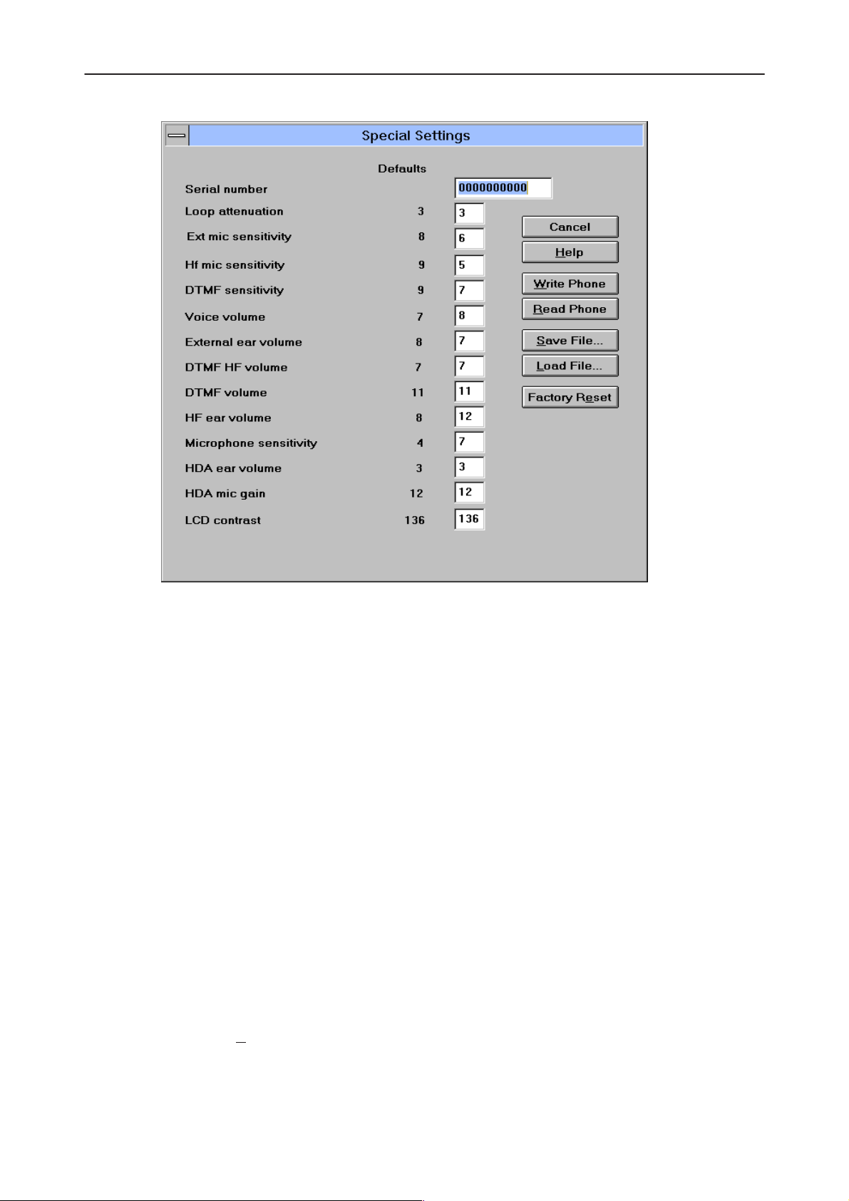
Special Settings
Activation Status Bar Text
Alt, E, S Wait! Initializing ...
This command is used to change some values in EEPROM. The list of the pa-
rameters and their typical values are below. In addition the contents of the EEPROM can be read to a file or from a file.
Function: Allowed values:
– serial number 10 digits
– loop attenuation 0...3
– EXT microphone sensitivity 0...15
– HF microphone sensitivity 0...15
– DTMF sensitivity 0...15
– voice volume 0...15
– EXT earphone volume 0...15
– DTMF HF volume 0...15
Technical Documentation
– DTMF volume 0...15
– HF earphone volume 0...15
– HDA ear volume 0...15
– HDA mic gain 0...15
– LCD Contrast 128...159
Page 48
Original 04/98
Page 49
PAMS
Service Software Instructions
Technical Documentation
NHN–5NT
The Special Settings dialog box contains the following items:
Cancel button (Alt+Esc):
The dialog box is closed.
Help button (Alt+H):
Opens help window.
Write Phone (ALT+W):
Writes special settings to the phone. Before writing the user is asked
to confirm the writing.
Read Phone (ALT+R):
Reads special settings from the phone and updates them to the display.
Save File (ALT+S):
Writes special settings to file. You can select the file to write to from
the File selection dialog box.
Load File (ALT+L):
Reads special settings from file. You can select a file to be loaded
from the File selection dialog box.
Factory Re
Original 04/98
set (ALT+E):
Page 49
Page 50

Service Software Instructions
PAMS
NHN–5NT
Resets the phone to factory values.
FFSK Data Sending Control
Activation Status Bar Text
Alt, E, F Wait! Initializing ...
This command is used to set the phone modem to send various signalling
frames as follows:
FFSK data transmission functions:
– signalling frame selection, with choice between 16 different types, plus trans-
mission of “1” state frequency (1200 Hz) or “0” state frequency (1800 Hz).
– transmit channel selection.
– number of signalling frame transmissions, with choice between one transmis-
sion and up to nine transmissions, short frame transmission A, or continuous
frame transmission B.
– transmission tuning, selectable between tuning off (normal state) or transmitter left on after end of transmission.
Technical Documentation
– transmit power selection.
– signalling frame transmission.
– stop sending.
Note: Use stop sending after sending even if there was only one frame to
send.
The Ffsk Data Sending Control dialog box contains the following items:
Page 50
Cancel button (Alt+Esc):
The dialog box is closed.
Help button (Alt+H):
Opens help window.
Original 04/98
Page 51

PAMS
Service Software Instructions
Technical Documentation
Send Frame button (Alt+S):
Sends selected frame.
Stop
Sending button (Alt+P):
Stops sending. Stop sending before you select another signalling
frame or another number of signalling frame transmissions
Tx channel (ALT+C) edit box:
This enables editing transmit channel.
Frame to send (ALT+F) list box:
Signalling frame selection, with choice between 16 different types,
plus transmission of “1” state frequency (1200 Hz) or “0” state frequency (1800 Hz).
Number of times to send (ALT+N) list box:
Select number of signalling frame transmissions, with choice between one transmission and up to nine transmissions, short frame
transmission A, or continuous frame transmission B.
Set control (ALT+E) combo box:
NHN–5NT
Transmission tuning selection, selectable between tuning off (normal
state) or transmitter left on after end of transmission.
TX l
evel (ALT+L) combo cox:
Transmit power selection (LOW / HIGH).
Original 04/98
Page 51
Page 52

Service Software Instructions
PAMS
NHN–5NT
Single Tone and DTMF Control
Activation Status Bar Text
Alt, E, T Wait! Initializing ...
This command displays a dialog box enabling tests of phone buzzer and DTMF
signal generator operation.
DTMF signal and buzzer tests:
– buzzer frequency
– DTMF signal transmission
– TX audio routing
– RX audio routing
– TX and RX audio routing
– buzzer audio routing
– audios muted
Technical Documentation
The Single Tone and DTMF Control dialog box contains the following items:
Cancel button (Esc):
The dialog box is closed.
Help button (Alt+H):
Opens help window.
Buzzer Volume button (Alt+B):
Opens buzzer volume dialog box, where buzzer volume (1...3) can
be entered.
Page 52
Original 04/98
Page 53

PAMS
Service Software Instructions
Technical Documentation
Dealer Menu
Selecting Dealer will bring up a sub–menu as shown below:
–Subscriber Data
–Short Code Memory
–Warranty Information
–Country Codes
–SMS Information
Subscriber Data
Activation Status Bar Text
Alt, D, S –
Selecting Dealer/Subscriber Data opens the subscriber data dialog box. In this
dialog, you can view and edit phone’s current subscriber data. The NHN5N
phone must be in local mode while writing subscriber data.
NHN–5NT
The Subscriber Data dialog box contains the following items:
Cancel button (Alt+Esc):
Help button (Alt+H):
Write Phone button (ALT+W):
Original 04/98
The dialog box is closed.
Opens help window.
Writes subscriber data to the phone. Before writing the user is asked
to confirm the writing.
Page 53
Page 54

Service Software Instructions
PAMS
NHN–5NT
Read Phone button (ALT+R):
Reads subscriber data from the phone and updates it to the display.
Phone number t
Add new ringing tone button (ALT+G):
Subscriber Number (ALT+U) edit box:
ransfer button(ALT+T):
Reads subscriber data and short code memory from one phone and
transfers them to another.
Adds new ringing tone. Select a file to be loaded from the File selection dialog box.
This enables programming a country code, a six–figure subscriber
number and a three–figure password as follows:
Z X 1 X 2 X 3 X 4 X 5 X 6 K 1 K 2 K 3 , where
Z is country selection as follows:
2 The Netherlands
3 Poland, Ukraine
Technical Documentation
4 Iceland/Estonia/OSS Carelian rep./Latvia/Lithuania/Romania/Bulgaria/OSS St. Petersburg/OSS Leningrad dist. / OSS Moscow/OSS Murmansk/Algeria
5 Denmark
6 Sweden
7 Norway
8 Finland
X 1 – X 6 is subscriber number
K 1 – K 3 is password
Delivery Date (ALT+D) edit box:
This enables entering the date of delivery in the form
ddmmyyyy
where dd is the day of the month using two figures, mm is the month
using two figures and yyyy represents the year as a four–figure
number.
Repair Date (ALT+P) edit box:
Repair date is programmed every time the phone has been repaired.
The form of the repair date is
Page 54
ddmmyy
where dd is the day of the month using two figures, mm is the month
using two figures and yy represents the year as a two–figure number.
Original 04/98
Page 55

PAMS
Service Software Instructions
Technical Documentation
Language (ALT+N) drop list:
This enables programming the language.
Menu language:
1. English : default
2. Other : first optional languge
Text Soft Indicator group:
Text soft indicator on (ALT+0) radio button:
Welcome message is shown on display instead of country code.
Text soft indicator off (ALT+F) radio button:
By default, text soft indicator is off.
Battery Save allowed check box:
This option enables activation of the NMT network battery preserving
function. When activated, it sets the phone into a low–consumption
mode for a period determined by the NMT exchange.
Sleep Mode allowed check box:
NHN–5NT
This option enables activation of the mobile’s sleep mode function.
When activated, the phone uses slower channel scanning when it is
in an area where the field strength is weak.
Own Number (ALT+B) edit box:
Own number is the number shown in short code memory location 99.
You can change the contents of the short code memory location 99
directly from th phone user interface too. Area code and subscriber
number are entered here, the subscriber number is shown. The own
number length for THF–10 is 30 digits.
Welcome Text (ALT+M) edit boxes:
This option enables defining for example the name of the phone
owner into the start call display. If the name is not entered here, the
subscriber’s number is shown. Welcome text length for THF–10 is 20
digits.
Lock Code (ALT+K) edit box:
This enables defining an individual lock, or prevent call, code for the
user.
Security Code (ALT+Y) edit box:
Basic Band 1 First (ALT+1) edit box:
Basic Band 1 Last (ALT+I) edit box:
Original 04/98
The phone’s security code is programmed here.
This number defines the first channel searched for the call. In the
Nordic countries the value 1 applies.
Page 55
Page 56

Service Software Instructions
PAMS
NHN–5NT
This number defines the last channel from which the calling channel
is searched. The value for the Nordic countries is 180.
Car Radio Mute / EXT alert group:
Car Radio Mute (ALT+C) radio button:
This option is used to select Car Radio Mute.
EXT alert (IGN check) q (ALT+Q) radio button:
This option is used to select Ext alert (IGN check).
EXT a
lert (no IGN check) (ALT+A) radio button:
This option is used to select EXT alert (no IGN check).
Short Code Memory
Activation Status Bar Text
Alt, D, M Short Code Memory
Selecting Dealer/Short Code Memory opens the short code memory dialog box.
In this dialog, you can view and edit all memory locations of the phone. You can
also store the information to a file and read information from a file.
Technical Documentation
The Short Code Memory dialog box is shown below:
In the editing dialog box, edit or type in a new name and number. You can
Tab
change the field with the
plete you are able to accept the new values and return to the full SCM dialog
Enter
box by pressing
the operation.
or by clicking the corresponding button.
key or clicking with a mouse. When this is com-
Esc
will cancel
Page 56
The Short Code Memory dialog box contains the following items:
Original 04/98
Page 57

PAMS
Service Software Instructions
Technical Documentation
Cancel button (Alt+Esc):
The dialog box is closed.
Help button (Alt+H):
Opens help window.
Write Phone (ALT+W):
Writes SCM data to the phone. Before writing the user is asked to
confirm the writing.
Read Phone (ALT+R):
Reads SCM data from the phone and updates it to the display.
Save File (ALT+S):
Writes SCM data to file. You can select the file to write to from the
File selection dialog box.
Load File (ALT+L):
Reads SCM data from file. You can select a file to be loaded from
the File selection dialog box.
NHN–5NT
Cle
ar SCM (ALT+E):
Clears SCM data and writes it to the phone. Before clearing the user
is asked to confirm the clearing.
Warranty Information
Activation Status Bar Text
Alt, D, W –
Selecting Dealer/Warranty Information opens the Warranty Information dialog.
In this dialog, you can view serial number, delivery date, software / hardware
versions, SIS–reference, latest dealer codes and repair dates.
Original 04/98
Page 57
Page 58

Service Software Instructions
PAMS
NHN–5NT
Technical Documentation
The Warranty Information dialog box contains the following items:
Cancel button (Alt+Esc):
Help button (Alt+H):
Read Phone (ALT+R):
Country Codes
Activation Status Bar Text
Alt, D, C –
Selecting Dealer/Country Codes opens the country codes dialog box. In this
dialog, you can view and edit codes / emergency numbers of the phone.
The example of country codes:
B Belgium
BY Belorussia
The dialog box is closed.
Opens help window.
Reads warranty information from the phone and updates it to the dis-
play.
Page 58
CS Czechoslovakia, Slovak
DK Denmark
EE, EW Estonia
FI Finland
Original 04/98
Page 59

PAMS
Service Software Instructions
Technical Documentation
FO Faroe Islands
HU Hungary
IS Iceland
LT Lithuania
LU Luxemburg
LV Latvia
MO Moscow
NL Holland
NO Norway
PL Poland
SE Sweden
SP St. Petersburg
NHN–5NT
The Country Codes dialog box contains the following items:
Cancel button (Alt+Esc):
The dialog box is closed.
Help button (Alt+H):
Opens help window.
Write Phone (ALT+W):
Writes country codes to the phone. Before writing the user is asked
to confirm the writing.
Read Phone (ALT+R):
Reads country codes from the phone and updates it to the display.
Y1 (ALT+Y), ID (ALT+ I), emerg 1 (ALT + 1), emerg 2 (ALT + 2), emerg 3
(ALT + 3) edit boxes:
These enable editing and entering country ID and emergency num-
bers. Note: Country Code can’t be edited.
Original 04/98
Page 59
Page 60

Service Software Instructions
PAMS
NHN–5NT
SMS Information
Activation Status Bar Text
Alt, V, I –
This command is used for editing own number and selecting validity period.
Own number must be programmed with international prefix (+) and country
code (t.ex. 358 Finland).
Technical Documentation
The SMS Information dialog box contains the following items:
Cancel button (Esc):
The dialog box is closed.
Help button (Alt+H):
Opens help window.
Write Phone (ALT+W):
Writes SMS information to the phone. Before writing the user is
asked to confirm the writing.
Read Phone (ALT+R):
Reads SMS information from the phone and updates it to the display.
Page 60
Original 04/98
Page 61

PAMS
Service Software Instructions
Technical Documentation
Help Menu
The Help Menu offers commands, which provide assistance with this application.
Index
Activation Status Bar Text
Alt, H, I –
Not implemented
General Help
Activation Status Bar Text
Alt, H, G
Not implemented
Using Help
NHN–5NT
Activation Status Bar Text
Alt, H, U
Not implemented
About WinTesla
Activation Status Bar Text
Alt, H, A .Shows the WinTesla software version, user interface,
M2BUS support, and NHN5N supporting DLL versions.
Original 04/98
Page 61
Page 62

Service Software Instructions
PAMS
NHN–5NT
Required Equipment
– At least 80386/33 MHz computer or compatible with one unused serial port
(COM1 or COM2), one parallel port (LPT1).
– WinTesla Software + NHN5N.DLL and NHN5EN.DLL.
– Operating system: DOS version 5.0 and Windows 3.11 or later.
– Display: VGA based display.
– Service Software program: WinTesla Software + NHN5N.DLL and
NHN5EN.DLL.
– M2BUS adapter DAU–2 and other service accessories; see equipment set-
up pictures.
– Software protection key PKD–1.
– Multimeter or DVM.
– Power supply
– DUPLEX radio telephone test station or separate measuring equipment as
follows:
Technical Documentation
– frequency counter (± 0.8 ppm)
– RF generator
– modulation analyzer
– attenuator
– AF generator
– power meter
– branching unit
– SINAD meter
Page 62
Original 04/98
Page 63

PAMS
Service Software Instructions
Technical Documentation
Tuning Instructions
Equipment setup
Turn off the computer before connecting to avoid possible damage to the serial
port.
Connect the M2BUS adapter (DAU–2, item 7) to the serial port (25–pin male
D–connector). In case your PC (as AT types in general) has a 9–pin serial port
use the special connector adapter cable provided (item 6).
Then connect the modular cable XCM–1 (item 4) from the M2BUS adapter to
the modular T–connector (item 3).
Then connect the modular cable XCM–1 (item 4) trom the first modular T–connector to the second modular T–connector. Now connect the transceiver
NHN–5N to the modular T–connector by using cable from test frame SCS–4B
(item 1).
Then connect external audio lines to the measurement station by using the audio cable ADS–1 (item 2).
NHN–5NT
Connect modular power connector SCF–6 (item 5) to the modular T–connector.
the supply voltage must be set to 6.5 V, when the phone is tuned.
For transmit and audio measuring and adjustment connect EAR/MIC breakout
cable ADS–1 as follows:
– EAR line to test equipment (Marconi 2960) AF INPUT
– MIC line to test equipment (Marconi 2955) AF GEN OUTPUT
Do not disconnect short coaxial jumpers between 2955/2960.
Note: The supply voltage must be set to 6.0 V, when battery and
charger referencies are tuned. Use of Service box JBS–7 is not
recommended.
Original 04/98
Page 63
Page 64

Service Software Instructions
PAMS
NHN–5NT
Technical Documentation
Equipment Setup
Equipment Setup for Tuning a Phone without Removing Covers
Item: Service accessory: Product code:
1 Service test cable (SCS–4B) 0730087
2 Audio cable, ADS–1 0730011
3 Modular T–connector 4626134
4 Modular cable, XCM–1 4626131
5 Modular power connector, SCF–6 0770036
6 RS–232 adapter (9 pin to 25 pin) 4626170
7 PC/M2BUS adapter, DAU–2 0750006
8 Service SW diskette 3.5” 0774019
8 Service SW diskette 5.25” 0774018
9 Software protection key PKD–1 0750018
10 RF Antenna Adapter XRC–1B 0730128
Page 64
Original 04/98
Page 65

PAMS
Service Software Instructions
Technical Documentation
Starting the Program
PClocals service software is delivered on a diskette and is copy protected with
PKD–1 SW protection key. The key must be present in the parallel port when
using the software. If you want to install the program to the hard disk, proceed
as follows:
1. Insert Service software disk into drive A of your PC.
2. Start Windows: Type WIN and press ENTER
3. Start Installing program: select File –> Run from Program Manager menu,
then type A:\INSTALL, and press OK button.
4. Follow Installation Software instruction.
The software is started by choosing WinTesla Icon under Windows.
Manual Tuning Steps
General
If any repairs or replacements have not been made, manual tuning is not necessary on the phone. Spare modules have been tuned at the factory. If some
repair or replacements have been made, manual tuning is nessessary.
NHN–5NT
If you do not want to use phone country version dependent tuning channels,
proceed as follows:
1. Choose RF controls from the Configure menu.
2. Change channel values.
3. Choose Write File –button in order to save channel values in ” TESLA.ini ”
–file.
The program saves the channel settings and uses them every time when Tunings or Testing menu is chosen. The program uses ordinary channels depending on the phone country version, if you don’t change channels.
Default channels in RF–controls dialog: Using:
Channel low for 1 band phones Afc and afc–limits tuning, basic settings
Channel mid for 1 band phones Afc and afc–limits tuning, basic settings
Channel high for 1 band phones Afc and afc–limits tuning, basic settings
Channel low for 2 band phones Afc and afc–limits tuning, basic settings
Channel mid for 2 band phones Afc and afc–limits tuning, basic settings
Channel high for 2 band phones Afc and afc–limits tuning, basic settings
Rssi channel low band 1 Rssi ch compensation
Rssi channel mid band 1 Rssi ch compensation,
Rssi levels and agc (1 band phones)
Rssi channel high band 1 Rssi ch compensation
Rssi channel low band 2 Rssi ch compensation
Rssi channel mid band 2 Rssi ch compensation
Original 04/98
Page 65
Page 66

Service Software Instructions
PAMS
NHN–5NT
Rssi channel high band 2 Rssi ch compensation
Rssi mid ch for 2 band phones Rssi levels and agc (2 band phones)
Tunings menu
1 – AFC Tuning
This dialog box is used for adjusting frequency for the phone middle channel.
The phone is turned to the default middle channel (RX and TX) and transmitter
is activated.
Note: Temperature during tuning should be approx. +25 °C.
AFC programming:
– Select Tunings/AFC frequency tuning
– Measurement device shows the AFC frequency D/A converter reading.
– Proceed with tuning until the value is within the middle TX frequency ± 0.3
kHz.
Technical Documentation
– Use the arrow keys or mouse to change the value and ALT–S to write the
value to EEPROM. The same control keys are used in TX Power Level, Deviation and AFC Limits tunings.
2 – AFC Limits Tuning
The progam asks to set the right RF–generator frequencies and signal levels. It
calculates the IF counter value. Use the arrow keys or mouse to change upper
and lower limit values (TX frequency +2.0 kHz and TX–frequency –2.0 kHz)
and press ALT–S to write the values to EEPROM.
3 – RSSI and AGC Tuning
Reference values for the received signal strength measurement are also tuned
with Pclocals. Adjustment is carried out with the help of an external signal generator. The program reads A/D converter values after the user has set the desired level to the signal generator.
RSSI programming:
– Select Tunings/RSSI and AGC Tuning
Page 66
– Program reads value given by A/D converter for received signal
– Program goes through three tuning points for channel compensation
– Program goes through five tuning points shown in the table below, then
returns to main menu
Original 04/98
Page 67

PAMS
Service Software Instructions
Technical Documentation
Tuning RF signal Level no
point level
1 –58 dBm 5
2 –68 dBm 4
3 –93 dBm 3
4 –103 dBm 2
5 –115 dBm 1
AGC programming:
– The program asks to set the RF signal levels
– The program shows the AGC ON level and the AGC OFF level
4 – Deviation Tuning
Deviation tuning procedure:
– Select Tunings/Deviation tuning
NHN–5NT
– Connect devices and set measurement device values according to info texts.
– Use the arrow keys or mouse to change tuning values and ALT–S to write
them to the phone. Use TAB key to change field.
– Compare measurement device value to the program info text value.
– Proceed until the above values are equal.
FFSK Deviation Tuning
This adjustment is used to set outgoing FFSK data deviation.
The command turns the phone to default middle channel (RX and TX), acti-
vates the transmitter, opens the data path, and sets up the modem to send a
continuous 1800 Hz, ”0” signal.
To adjust, give some values (0–15) for the D/A converter, and compare results
to the reading given by the deviation meter.
Nominal Deviation Tuning
The purpose of this tuning operation is to adjust the nominal deviation of voice
and DTMF signaling.
The command turns the phone to the default middle channel, and activates the
transmitter.
To adjust, enter values from the range 0–7 into the D/A converter and compare
results with deviation meter readings.
Original 04/98
Page 67
Page 68

Service Software Instructions
PAMS
NHN–5NT
Maximum Deviation Tuning
This adjustment has an effect on voice and DTMF signal maximum deviation.
The command turns the phone on the default middle channel, and activates the
transmitter.
Enter various values from the range 0–7 into the D/A converter, and compare
results with the reading in the deviation meter.
Note: Deviation will increase when D/A reading is decreased.
Phi Signal Deviation Tuning
The purpose of this adjustment is to adjust $ signal (SAT) deviation.
The command turns the phone on the default middle channel (RX and TX), ac-
tivates transmitter, and enables the φ loop.
To adjust, enter a fe– values (0–15) to the D/A converter and
compare changes to deviation meter readings.
Technical Documentation
5 – TX Output Power Tuning
This adjustment writes the power levels of the phone transmitter into the EEPROM. When doing this, a power meter must be used. NHN–5NT has three
power levels to tune. Power levels low and middle are adjusted only at band 3.
Power level high is tuned at all four bands.
Programming can be interrupted when necessary by pressing Esc key.
Power levels tuning procedure:
– Connect power meter to the antenna connector of the phone.
– Adjust the phone supply voltage to +6.5 V !
– Select Tunings/TX output power
– Use the arrow keys, Page up/down keys or mouse to change the tuning val-
ue.
– Change tuning value until the power meter value is at the target value.
– Use TAB key to change field and ALT–S to write values to EEPROM.
6 – Battery Voltage Tuning
Page 68
A reference value for battery voltage is set by using an accurate 6.0 V supply.
Battery voltage tuning procedure:
– Connect dummy battery to phone and set supply voltage to 6.0 V.
– Select Tunings/Battery voltage tuning
Original 04/98
Page 69

PAMS
Service Software Instructions
Technical Documentation
– The program reads the 6.0 V, A/D reading fed to VBAT line.
7 – Charger Voltage Tuning
The reference value for the charge voltage is adjusted by using an accurate
6.0 V power supply.
Charger voltage tuning procedure:
– Connect modular power connector SCF–6 to modular T–Adapter.
– Select Tunings/Charger voltage tuning
– Program reads 6.0 V, A/D reading fed to phone VCHARG line.
8 – LCD Contrast Tuning
LCD Contrast tuning procedure:
– Select Tunings/LCD Contrast tuning
– Use the arro– keys or mouse to change tuning value and ALT–S to write it to
the phone.
NHN–5NT
– LCD Contrast must be between 128...159. Default value is 136.
– Tune until LCD Contrast is good.
9 – Show Tuning Values
This dialog box enables reading of the phone tuning parameters, and writing of
the default values.
Note: Spare modules received from the factory are factory–tuned.
Original 04/98
Page 69
Page 70

Service Software Instructions
PAMS
NHN–5NT
Appendix 1, Vocabulary
Abbreviation Description
API Application Programming Interface
ASIC Custom circuit which for instance controls communication between
MCU and DSP
CLF Common Look and Feel
DATA DATA interface module
DAU–4S M2BUS – RS–232 adapter
DLL Dynamic Link Library
EEPROM Memory for adjustment parameters (Electrically Erasable and
Programmable Read Only Memory)
M2BUS Serial communication bus which can be connected to
accessory devices and test PC
MCU Master Control Unit processor
Technical Documentation
ME Mobile Equipment
MFC Microsoft Foundation Class library
MS Mobile Station
MTI Message Transfer Interface
PC IBM PS/AT or compatible personal computer
PCBOX Local Net driver SW for PC
PCI Phone Controlling Interface SW for PC
PKD Parallel Port Software Protection Device
RF Radio Frequency parts
SW Software
UI User Interface
Page 70
Original 04/98
 Loading...