

Page 1

Nokia Customer Care
Service Manual
RH-109 (Nokia 1606Arte; L3&4)
Mobile Terminal
Part No: (Issue 2)
COMPANY CONFIDENTIAL
Copyright © 2008 Nokia. All rights reserved.
Page 2
Amendment Record Sheet
RH-109
Amendment Record Sheet
Amendment No Date Inserted By Comments
Issue 1 2008.05.13 Michelle Wang Initial draft
Issue 2 2008.07.17 Michelle Wang Updated version
Page ii COMPANY CONFIDENTIAL Issue 1
Copyright © 2008 Nokia. All rights reserved.
Page 3

RH-109
Copyright
Copyright
Copyright © 2008 Nokia. All rights reserved.
Reproduction, transfer, distribution or storage of part or all of the contents in this document in any form without
the prior written permission of Nokia is prohibited.
Nokia, Nokia Connecting People, and Nokia X and Y are trademarks or registered trademarks of Nokia
Corporation. Other product and company names mentioned herein may be trademarks or tradenames of their
respective owners.
Nokia operates a policy of continuous development. Nokia reserves the right to make changes and
improvements to any of the products described in this document without prior notice.
Under no circumstances shall Nokia be responsible for any loss of data or income or any special, incidental,
consequential or indirect damages howsoever caused.
The contents of this document are provided "as is". Except as required by applicable law, no warranties of any
kind, either express or implied, including, but not limited to, the implied warranties of merchantability and
fitness for a particular purpose, are made in relation to the accuracy, reliability or contents of this document.
Nokia reserves the right to revise this document or withdraw it at any time without prior notice.
The availability of particular products may vary by region.
IMPORTANT
This document is intended for use by qualified service personnel only.
Issue 1 COMPANY CONFIDENTIAL Page iii
Copyright © 2008 Nokia. All rights reserved.
Page 4

Warnings and Cautions
RH-109
Warnings and cautions
Warnings
z IF THE DEVICE CAN BE INSTALLED IN A VEHICLE, CARE MUST BE TAKEN ON INSTALLATION IN VEHICLES FITTED WITH
ELECTRONIC ENGINE MANAGEMENT SYSTEMS AND ANTI-SKID BRAKING SYSTEMS. UNDER CERTAIN FAULT
CONDITIONS, EMITTED RF ENERGY CAN AFFECT THEIR OPERATION. IF NECESSARY, CONSULT THE VEHICLE DEALER/
MANUFACTURER TO DETERMINE THE IMMUNITY OF VEHICLE ELECTRONIC SYSTEMS TO RF ENERGY.
z THE PRODUCT MUST NOT BE OPERATED IN AREAS LIKELY TO CONTAIN POTENTIALLY EXPLOSIVE ATMOSPHERES, FOR
EXAMPLE, PETROL STATIONS (SERVICE STATIONS), BLASTING AREAS ETC.
z OPERATION OF ANY RADIO TRANSMITTING EQUIPMENT, INCLUDING CELLULAR TELEPHONES, MAY INTERFERE WITH
THE FUNCTIONALITY OF INADEQUATELY PROTECTED MEDICAL DEVICES. CONSULT A PHYSICIAN OR THE
MANUFACTURER OF THE MEDICAL DEVICE IF YOU HAVE ANY QUESTIONS. OTHER ELECTRONIC EQUIPMENT MAY ALSO
BE SUBJECT TO INTERFERENCE.
z BEFORE MAKING ANY TEST CONNECTIONS, MAKE SURE YOU HAVE SWITCHED OFF ALL EQUIPMENT.
Cautions
z Servicing and alignment must be undertaken by qualified personnel only.
z Ensure all work is carried out at an anti-static workstation and that an anti-static wrist strap is worn.
z Ensure solder, wire, or foreign matter does not enter the telephone as damage may result.
z Use only approved components as specified in the parts list.
z Ensure all components, modules, screws and insulators are correctly re-fitted after servicing and alignment.
z Ensure all cables and wires are repositioned correctly.
z Never test a mobile phone WCDMA transmitter with full Tx power, if there is no possibility to perform the
measurements in a good performance RF-shielded room. Even low power WCDMA transmitters may disturb
nearby WCDMA networks and cause problems to 3G cellular phone communication in a wide area.
z During testing never activate the GSM or WCDMA transmitter without a proper antenna load, otherwise GSM
or WCDMA PA may be damaged.
Page iv COMPANY CONFIDENTIAL Issue 1
Copyright © 2008 Nokia. All rights reserved.
Page 5

RH-109
For your safety
For your safety
QUALIFIED SERVICE
Only qualified personnel may install or repair phone equipment.
ACCESSORIES AND BATTERIES
Use only approved accessories and batteries. Do not connect incompatible products.
CONNECTION TO OTHER DEVICES
When connecting to any other device, read its user’s guide for detailed safety instructions. Do not connect
incompatible products.
Issue 1 COMPANY CONFIDENTIAL Page v
Copyright © 2008 Nokia. All rights reserved.
Page 6
Care and Maintenance
RH-109
Care and maintenance
z This product is of superior design and craftsmanship and should be treated with care. The suggestions
below will help you to fulfill any warranty obligations and to enjoy this product for many years.
z Keep the phone and all its parts and accessories out of the reach of small children.
z Keep the phone dry. Precipitation, humidity and all types of liquids or moisture can contain minerals that
will corrode electronic circuits.
z Do not use or store the phone in dusty, dirty areas. Its moving parts can be damaged.
z Do not store the phone in hot areas. High temperatures can shorten the life of electronic devices, damage
batteries, and warp or melt certain plastics.
z Do not store the phone in cold areas. When it warms up (to its normal temperature), moisture can form
inside, which may damage electronic circuit boards.
z Do not drop, knock or shake the phone. Rough handling can break internal circuit boards.
z Do not use harsh chemicals, cleaning solvents, or strong detergents to clean the phone.
z Do not paint the phone. Paint can clog the moving parts and prevent proper operation.
z Use only the supplied or an approved replacement antenna. Unauthorized antennas, modifications or
attachments could damage the phone and may violate regulations governing radio devices.
All of the above suggestions apply equally to the product, battery, charger or any accessory.
Page vi COMPANY CONFIDENTIAL Issue 1
Copyright © 2008 Nokia. All rights reserved.
Page 7

RH-109
ESD protection
ESD protection
Nokia requires that service points have sufficient ESD protection (against static electricity) when servicing the
phone.
Any product of which the covers are removed must be handled with ESD protection. The SIM card can be replaced
without ESD protection if the product is otherwise ready for use.
To replace the covers ESD protection must be applied.
All electronic parts of the product are susceptible to ESD. Resistors, too, can be damaged by static electricity
discharge.
All ESD sensitive parts must be packed in metallized protective bags during shipping and handling outside any
ESD Protected Area (EPA).
Every repair action involving opening the product or handling the product components must be done under ESD
protection.
ESD protected spare part packages MUST NOT be opened/closed out of an ESD Protected Area.
For more information and local requirements about ESD protection and ESD Protected Area, contact your local
Nokia After Market Services representative.
Issue 1 COMPANY CONFIDENTIAL Page vii
Copyright © 2008 Nokia. All rights reserved.
Page 8

Battery information
RH-109
Battery information
Note: A new battery's full performance is achieved only after two or three complete charge and
discharge cycles!
The battery can be charged and discharged hundreds of times but it will eventually wear out. When the
operating time (talk-time and standby time) is noticeably shorter than normal, it is time to buy a new battery.
Use only batteries approved by the phone manufacturer and recharge the battery only with the chargers
approved by the manufacturer. Unplug the charger when not in use. Do not leave the battery connected to a
charger for longer than a week, since overcharging may shorten its lifetime. If left unused a fully charged battery
will discharge itself over time.
Temperature extremes can affect the ability of your battery to charge.
For good operation times with Li-Ion batteries, discharge the battery from time to time by leaving the product
switched on until it turns itself off (or by using the battery discharge facility of any approved accessory available
for the product). Do not attempt to discharge the battery by any other means.
Use the battery only for its intended purpose.
Never use any charger or battery which is damaged.
Do not short-circuit the battery. Accidental short-circuiting can occur when a metallic object (coin, clip or pen)
causes direct connection of the + and - terminals of the battery (metal strips on the battery) for example when
you carry a spare battery in your pocket or purse. Short-circuiting the terminals may damage the battery
or the connecting object.
Leaving the battery in hot or cold places, such as in a closed car in summer or winter conditions, will reduce the
capacity and lifetime of the battery. Always try to keep the battery between 15°C and 25°C (59°F and 77°F). A
phone with a hot or cold battery may temporarily not work, even when the battery is fully charged.
Batteries' performance is particularly limited in temperatures well below freezing.
Do not dispose of batteries in a fire!
Dispose of batteries according to local regulations (e.g. recycling). Do not dispose as household waste.
Page viii COMPANY CONFIDENTIAL Issue 1
Copyright © 2008 Nokia. All rights reserved.
Page 9

RH-109
Company Policy
Company Policy
Our policy is of continuous development; details of all technical modifications will be included with service
bulletins.
While every endeavour has been made to ensure the accuracy of this document, some errors may exist. If any
errors are found by the reader, NOKIA MOBILE PHONES Business Group should be notified in writing/e-mail.
Please state:
z Title of the Document + Issue Number/Date of publication
z Latest Amendment Number (if applicable)
z Page(S) and/or Figure(s) in error
Please send to:
NOKIA CORPORATION
Nokia Mobile Phones Business Group
Nokia Customer Care
PO Box 86
FIN-24101 SALO
Finland
E-mail: Service.Manuals@nokia.com
Issue 1 COMPANY CONFIDENTIAL Page ix
Copyright © 2008 Nokia. All rights reserved.
Page 10

Company Policy
RH-109
(This page left intentionally blank.)
Page x COMPANY CONFIDENTIAL Issue 1
Copyright © 2008 Nokia. All rights reserved.
Page 11

RH-109
Nokia 1606Arte Service Manual Structure
Nokia 1606Arte Service Manual Structure
1. General information
2. Service Devices and Service Concepts
3. BB Troubleshooting and Manual Tuning Guide
4. RF Troubleshooting
5. System Module Description
Glossary
Issue 1 COMPANY CONFIDENTIAL Page xi
Copyright © 2008 Nokia. All rights reserved.
Page 12

Nokia 1606Arte Service Manual Structure
RH-109
(This page left intentionally blank.)
Page xii COMPANY CONFIDENTIAL Issue 1
Copyright © 2008 Nokia. All rights reserved.
Page 13

Nokia Customer Care
1 – General information
Issue 1 COMPANY CONFIDENTIAL Page 1-1
Copyright © 2008 Nokia. All rights reserved.
Page 14

General information
RH-109
(This page left intentionally blank.)
Page 1-2 COMPANY CONFIDENTIAL Issue 1
Copyright © 2008 Nokia. All rights reserved.
Page 15

RH-109
General information
Table of Contents
Product selection…………………………………………………………………………………………………………………………………….…..1-5
Phone features……………………………………………………………………………………………………………………………….……….…..1-5
User interface and software features……………………………………………………………………………………………….……….…..1-6
Accessories……………………………………………………………………………………………….…………………………………………….…..1-6
Technical specifications……………………………….…………………………………………….…………………………………………….…..1-6
General specifications…………………………….…………………………………………….…………………………………………….…..1-6
Battery endurance…………………………………….………………………………………….…………………………………………….…..1-6
List of Figures
Figure 1 RH-109 (Nokia 1606Arte) product picture…………………………………………………………………………………….…..1-5
Issue 1 COMPANY CONFIDENTIAL Page 1-3
Copyright © 2008 Nokia. All rights reserved.
Page 16

General information
RH-109
(This page left intentionally blank.)
Page 1-4 COMPANY CONFIDENTIAL Issue 1
Copyright © 2008 Nokia. All rights reserved.
Page 17
RH-109
General information
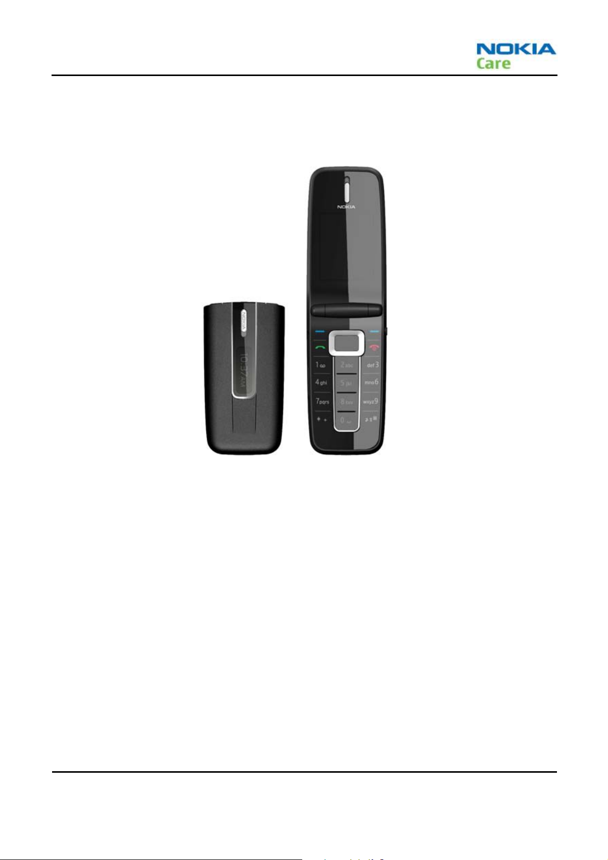
Product selection
Rh-109 (Nokia 1606) is a CDMA200 triple band phone, supporting CDMA2000 1Xrtt /Cell/PCS/AWS bands.
Figure 1 RH-109 (Nokia 1606Arte) product picture
Phone features
Display and keypad features
z 1.77” 128x160 pixel, 262k true color internal display
z 0.97” 96x32 pixel, white monochrome external display
z 5-way , navi-key (4 way scroll and center key, call and end keys with intelligent key light+)
Hardware features
z Micro USB port for charging and data transfer (USB 2.0+)
z 2.5 phi dedicate headset
z Internal vibrator and antenna
z Internal 512Mb memory
z Torch feature in power on/off
z Support E911
RF features
z CDMA2000 1Xrtt: Cell/PCS/AWS
z AGPS/SGPS: E911 feature only
Issue 1 COMPANY CONFIDENTIAL Page 1-5
Copyright © 2008 Nokia. All rights reserved.
Page 18
General information
RH-109
User interface and software features
Selection of software applications and services
z 3GPP streaming / downloading videq
z Themes (wallpapers, icons, colors+
z Music Player supporting MP3,Midi, QCELP and EVRC
z OMA DRM 1.0
z OMA MMS 1.2, MMS Conformance 3.0, AMR and SMIL
z OMA Client Provisioning v1.3
z MP3 ringing tones, true tones and MIDI ringing, alert and gaming tones with support of 64 polyphone
z HTTP 1.1/WAP2.0
z Nokia PC Suite
Accessories
Sales package contents
z Nokia 1606 phone
z Nokia Battery BL-4B
z Nokia Charger: AC-6,
z User Guide
Technical specifications
General specifications
Unit Dimension(mm) Weight(g) Volume(cc)
Transceiver with BL-4B 700mA
Li-Ion battery pack
85x45x16.5 76 48
Battery endurance
Battery NMP Talk time NMP Standby time
BL-4B 700mAh Li-Ion battery Up to 3.5 hours 10 days
Note: The variation in operation times will occur depending on network parameters, phone setting and usage.
Page 1-6 COMPANY CONFIDENTIAL Issue 1
Copyright © 2008 Nokia. All rights reserved.
Page 19

RH-109
General information
(This page left intentionally blank.)
Issue 1 COMPANY CONFIDENTIAL Page 1-7
Copyright © 2008 Nokia. All rights reserved.
Page 20

Nokia Customer Care
2 – Service Devices and
Service Concepts
Issue 1 COMPANY CONFIDENTIAL Page 2-1
Copyright © 2008 Nokia. All rights reserved.
Page 21

Service Devices and Service Concepts
RH-109
(This page left intentionally blank.)
Page 2-2 COMPANY CONFIDENTIAL Issue 1
Copyright © 2008 Nokia. All rights reserved.
Page 22
RH-109
Service Devices and SW Update
Table of Contents
Service Devices….………………………………………………………………………………………….......................….............................2-5
Product specific devices………………………………………………………………………………........................….............................2-5
MJ-199.............…………………………………………………………………………………………………………......................................2-5
RJ-230............................................…………………………………………………………………………………...................................2-5
SS-179.............................................………………………………………………………………………………………...........................2-5
Cables..........................................………………………………………………………………………………………...................................2-5
CA-128RS.................................………………………………………………………………………………………...................................2-5
PCS-1...................................………………………………………………………………………………………........................................2-6
Service concepts.....................……………………………………………………………………………………........................................2-6
POS (Point of Sale) flash concept…………………………………………………………………………...........................................2-6
SW download….………………………………………………………………………………………………...................................................2-7
Introduction……………………………………………..………………………………………………......................................................2-7
Operation guide……………………...................................................................................................................................2-7
Single bundle download tool ......................................................................................................................................2-7
Multi bundle download tool ........................................................................................................................................2-8
Single download tool .................................................................................................................................................2-10
Died phone revive tool ...............................................................................................................................................2-11
Issue 1 COMPANY CONFIDENTIAL Page 2-3
Copyright © 2008 Nokia. All rights reserved.
Page 23
Service Devices and Service Concepts
RH-109
(This page left intentionally blank.)
Page 2-4 COMPANY CONFIDENTIAL Issue 1
Copyright © 2008 Nokia. All rights reserved.
Page 24
RH-109
Service Devices and SW Update
Service Devices
Product specific devices
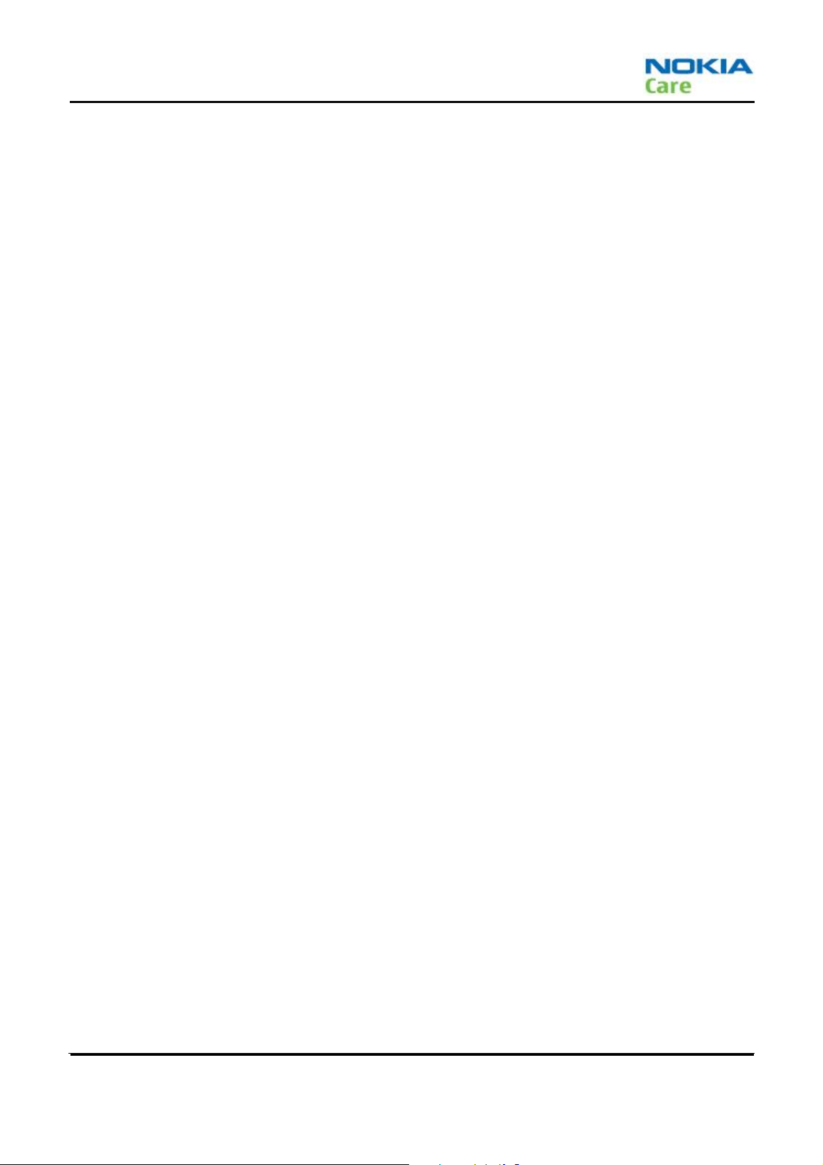
The table below gives a short overview of service tools that can be used for testing, error analysis and repair of
product RH-109, refer to various concepts.
MJ-199 Module Jig
This device holds the PWB during testing. It has a serial port interface
to connect to the service software.
RJ-230 Universal Soldering Jig
RJ-230 is a soldering jig used for soldering and as a rework jig for the
engine module.
SS-179 Domesheet Alignment Jig
This jig is used when replacing the domesheet on the PWB to ensure
correct alignment.
Cables
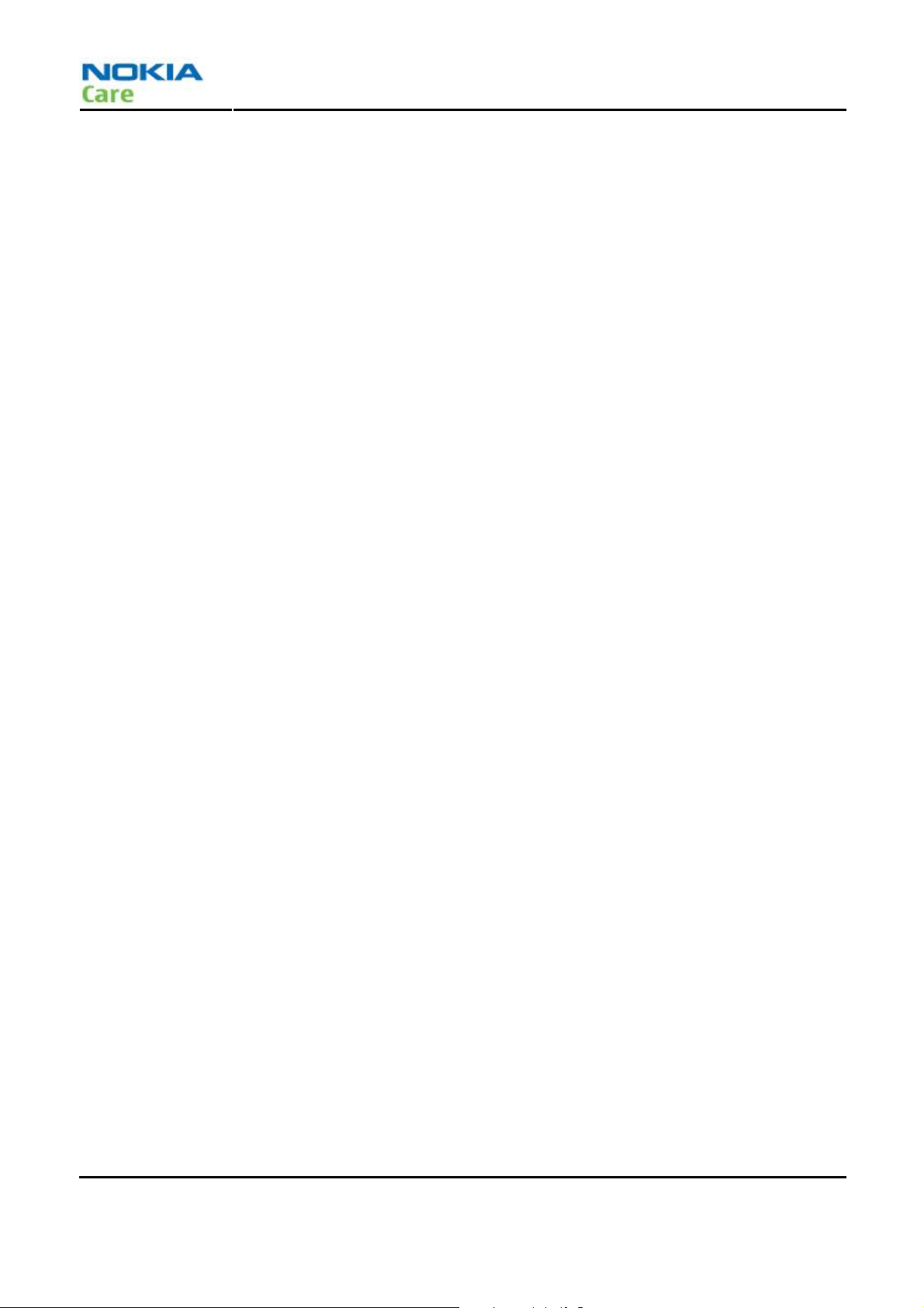
The table below gives a short overview of service tools that can be used for testing, error analysis and repair of
product RH-109, refer to various concepts.
CA-128RS RF cable
The RF cable is used to connect, for example, a module repair jig to
the RF measurement equipment.
Attenuation for:
• Cell band: 0.51
• PCS band: 0.85
• AWS Tx band: 0.75
Issue 1 COMPANY CONFIDENTIAL Page 2-5
Copyright © 2008 Nokia. All rights reserved.
Page 25
Service Devices and Service Concepts
RH-109
SW Update
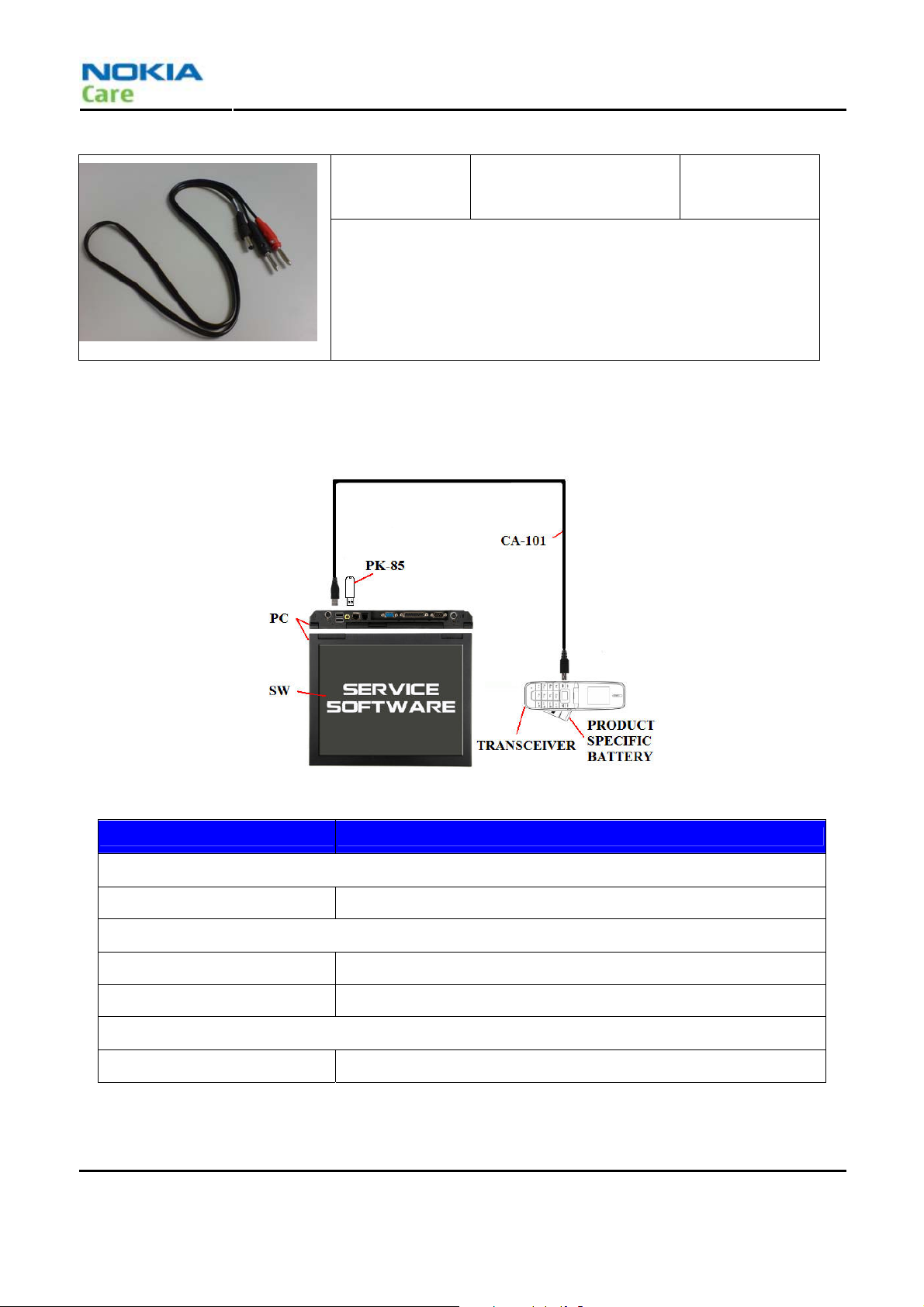
POS (Point of Sale) flash concept
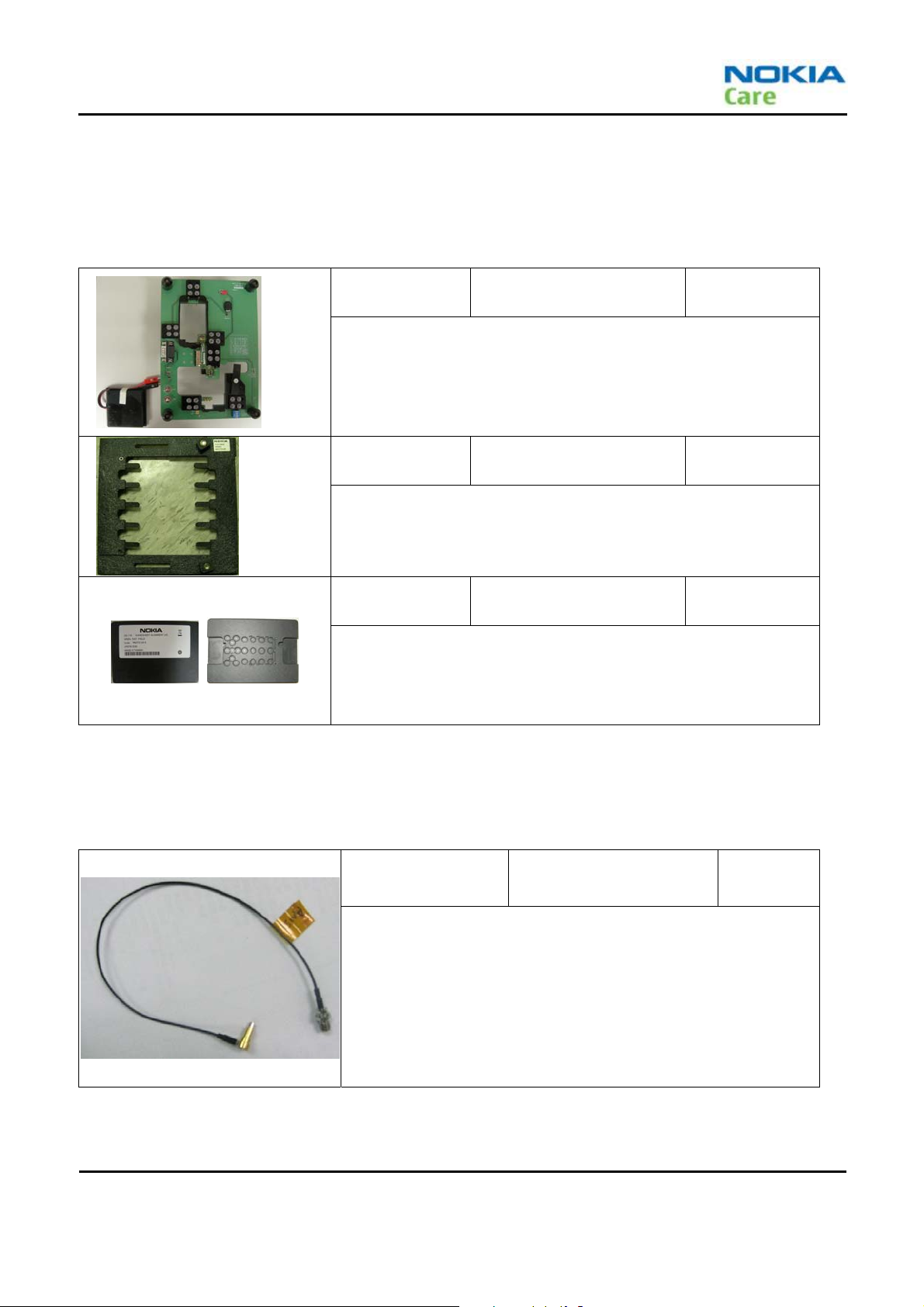
PCS-1 Power cable
The PCS-1 power cable (DC) is used with a docking station, a module jig
or a control unit to supply a controlled voltage.
Type Description
Product specific tools
BL-4B Battery
Other tools
PK-85 USB dongle
PC with PST software
Cables
CA-101 USB connectivity cable
Page 2-6 COMPANY CONFIDENTIAL Issue 1
Copyright © 2008 Nokia. All rights reserved.
Page 26
RH-109
Service Devices and SW Update
Software download
Introduction
Purpose
The purpose of this section is to show the PST download tool operation steps. User can follow the operation
sequence, step by step, to complete the image downloading procedure. This section also shows users what
should be careful during downloading.
Scope
This section will show the operations sequence of Single bundle downloading, multi-bundle downloading and
single download tool with dead phone revive function.
Definitions, Acronyms, and Abbreviations
PST Product Service Tool / Product Support Tool
CPC Customer Product Code / Customer Protect Code
MSI Microsoft Installer
Reference
http://msdn2.microsoft.com/en-us/library/wtzawcsz(VS.80).aspx
Operation guide
Requirements and Notices
z USB Driver:Before using those tools, user should install the USB driver firstly then connect phone to PC to
register phone into PC or the PC can’t identify the phone. User can open device manager to check your
phone can be identified by PC or not.
z PST Tool:These tools are included in PST tool and can’t be used or started without launching from PST tool.
Please get valid PST tool packet from the vendor or legal web-site.
z MSI image:Before starting downloading, user should get valid image packet from your vendor or legal
web-site. During download, please don’t plug-out USB cable or any other USB devices to avoid PC unstable
issues.
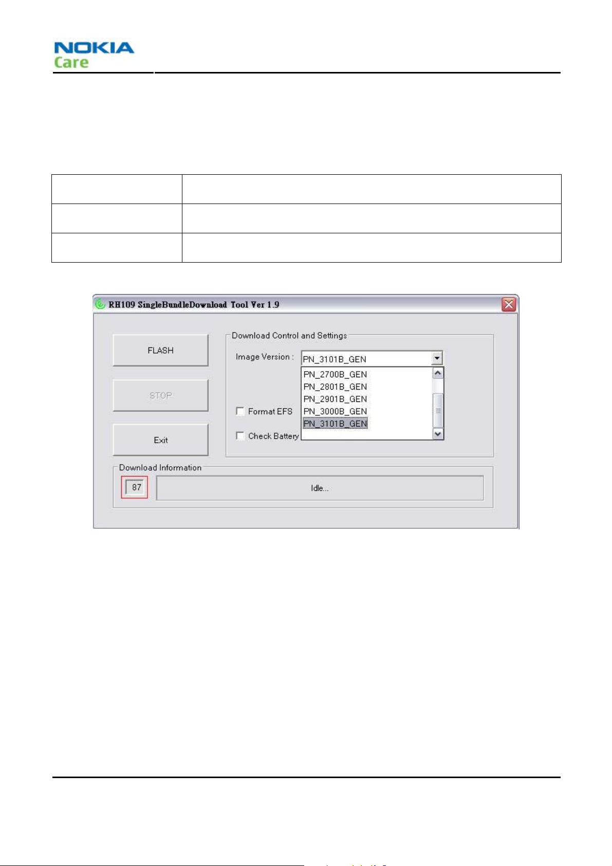
Single bundle download tool
z Power on phone and connected to computer via USB cable.
z Launch PST tool then select Single Bundle Download Tool by clicking “Bundle Downloader” button on
“Downloader” page. Make sure the CPC is not empty on “Phone info” page before switching to
“Downloader” page.
z Select Proper image version from the dropdown menu. If the dropdown menu shows “No valid images”, it
means you don’t install proper MSI image packet or the CPC code is empty. Please check it and re-starting
again.
z Make sure the COM port number on the left-bottom un-edit field is the same as you see from device
manager then clicking “FLASH” button to start downloading.
Issue 1 COMPANY CONFIDENTIAL Page 2-7
Copyright © 2008 Nokia. All rights reserved.
Page 27
Service Devices and Service Concepts
z The progress bar will show the downloading progress and messages during downloading, please wait
programming is completed when “Download Finished” message box pop-up and the progress bar color
becomes green.
z Close tool by clicking “Exit” button.
Image Version
Format EFS
Check Battery
Must be chosen manually. It lists the image version that user installed on this
computer and which version user wants to download to phone.
It’s an option that formatting the phone file system without User Data
backup/restore during downloading.
It’s an option that check connected battery level before starting downloading
images into phone to protect downloading procedure.
RH-109
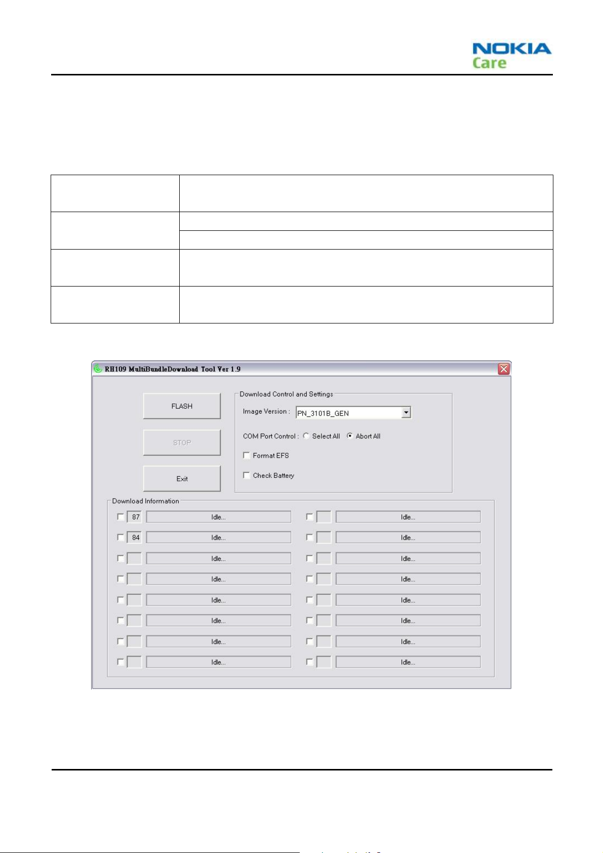
Multi bundle download tool
z Power on phones and connected them to computer via USB cable.
z Launch PST tool then select Multi-Bundle Download Tool by clicking “Multi Downloader” button on
“Downloader” page. Make sure the CPC is not empty on “Phone info” page before switching to
“Downloader” page.
z Select Proper image version from the dropdown menu. If the dropdown menu shows “No valid images”, it
means you don’t install proper MSI image packet or the CPC code is empty. Please check it and re-starting
again.
z Make sure the COM port numbers in front of each progress bar can also be seen in device manager. Mark the
selection button in front of each COM port number field to make sure user want to programming the phone
connected to this port.
z Click “FLASH” button to start downloading.
Page 2-8 COMPANY CONFIDENTIAL Issue 1
Copyright © 2008 Nokia. All rights reserved.
Page 28
RH-109
Service Devices and SW Update
z The progress bar will show the downloading progress and messages during downloading, please wait
programming is completed when “Download Finished” message box pop-up and the progress bar color
becomes green.
z Close tool by clicking “Exit” button.
Must be chosen manually. It lists the image version that user installed on this
Image Version
computer and which version user wants to download to phone.
“Select All” means select all connected phones.
COM port control
“Abort All” means abort all connected phones.
It’s an option that formatting the phone file system without User Data
Format EFS
backup/restore during downloading.
It’s an option that check connected battery level before starting downloading
Check Battery
images into phone to protect downloading procedure.
Issue 1 COMPANY CONFIDENTIAL Page 2-9
Copyright © 2008 Nokia. All rights reserved.
Page 29
Service Devices and Service Concepts
RH-109
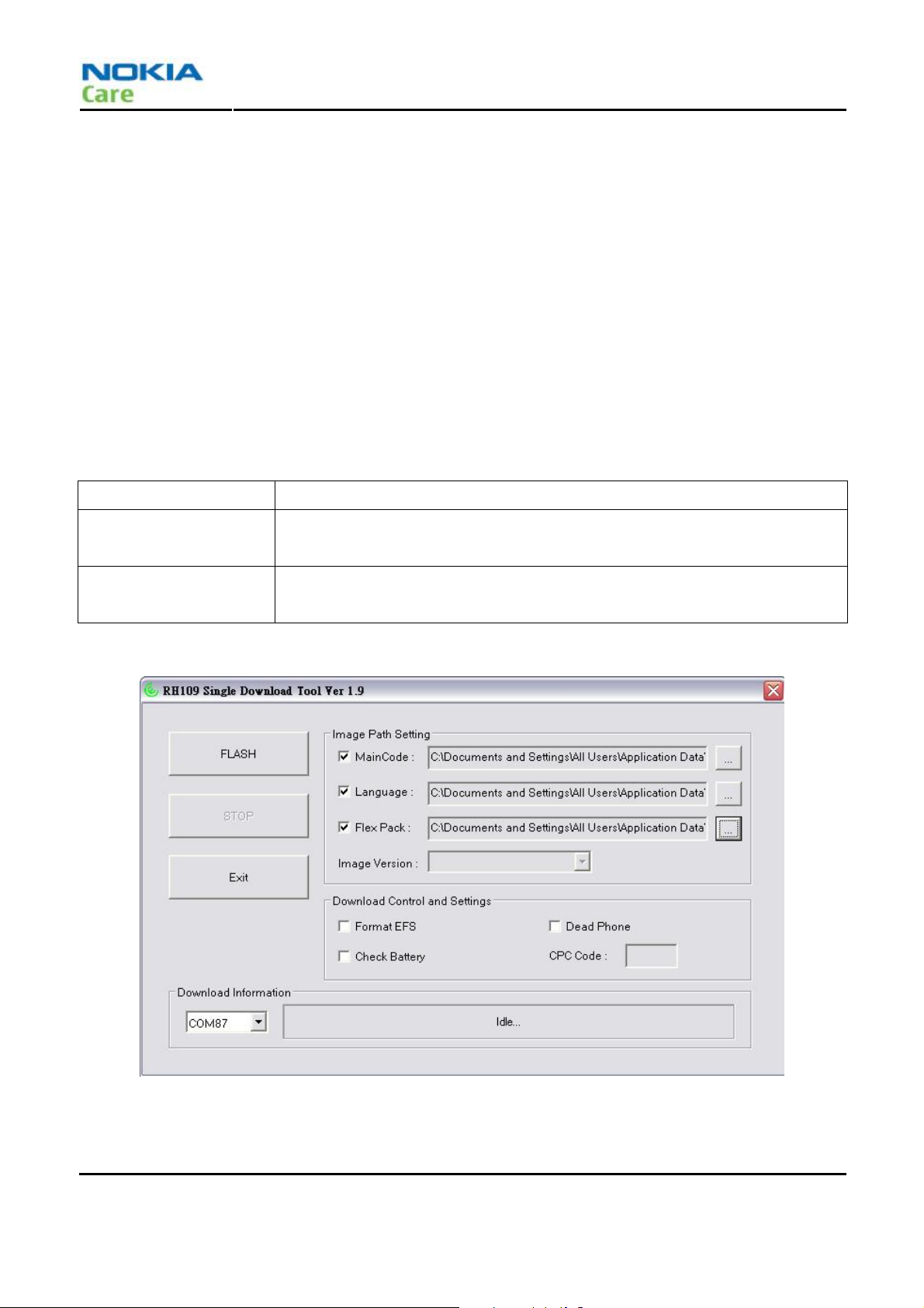
Single download tool
z Power on phone and connected them to computer via USB cable.
z Make sure level 3 or RD level USB dongle is inserted into compute.
z Launch PST tool then select Single Download Tool by clicking “Single Downloader” button on “Downloader”
page. Make sure the CPC is not empty on “Phone info” page before switching to “Downloader” page.
z Select proper images by clicking the button in back of the MainCode path, Language path and Flex Pack
path fields. Make sure the selection button is selected in front of each image paths if user wants to
download it.
z Make sure the COM port numbers in front of the progress bar can also be seen in device manager then
clicking “FLASH” button to start downloading.
z The progress bar will show the downloading progress and messages during downloading, please wait
programming is completed when “Download Finished” message box pop-up and the progress bar color
becomes green.
z Close tool by clicking “Exit” button.
Dead Phone
Switch to dead phone revive function.
Format EFS
Check Battery
It’s an option that formatting the phone file system without User Data
backup/restore during downloading.
It’s an option that check connected battery level before starting downloading
images into phone to protect downloading procedure.
Page 2-10 COMPANY CONFIDENTIAL Issue 1
Copyright © 2008 Nokia. All rights reserved.
Page 30
RH-109
Service Devices and SW Update
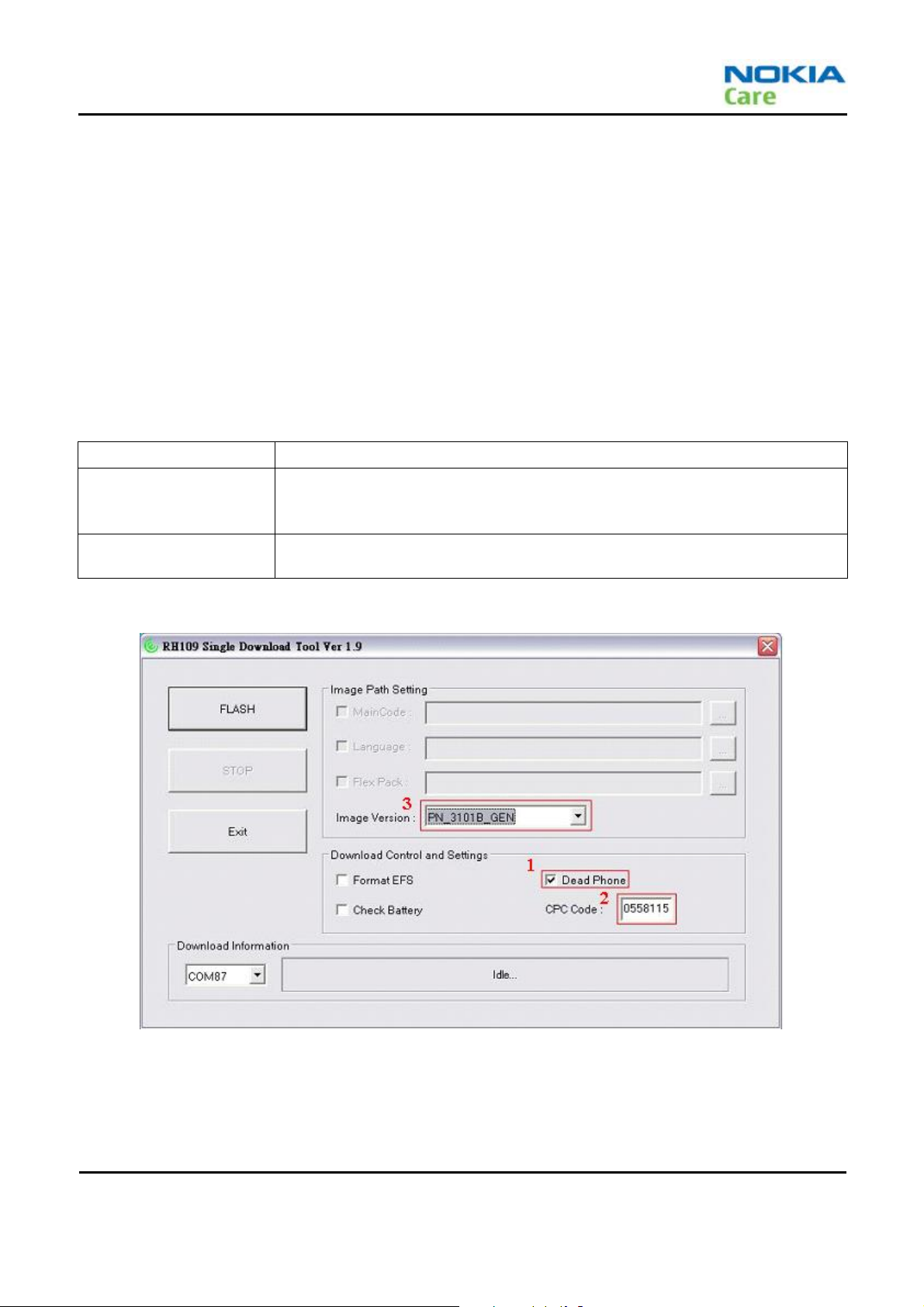
Died phone revive tool
z Power on phone into download mode and connected them to computer via USB cable.
z Make sure level 3 or RD level USB dongle is inserted into compute.
z Launch PST tool then select Died Phone Revive Tool by clicking “Died Phone Recover” button on “Device
Select” dialog and user will be “Single Download Tool” is showed up.
z Mark “Dead Phone” selection button to switch to dead phone reviving function.
z Input valid and proper CPC code to enable dropdown menu. Select the proper image version as used on
Bundle Download Tool then click “FLASH” button to start downloading.
z The progress bar will show the downloading progress and messages during downloading, please wait
programming is completed when “Download Finished” message box pop-up and the progress bar color
becomes green.
z Close tool by clicking “Exit” button.
Dead Phone
Format EFS
Check Battery
Switch back to Single Download Tool.
If user do dead phone revive function, downloading procedure will force phone
doing file system formatting whether user mark “Format EFS” selection button or
not.
It’s an option that check connected battery level before starting downloading
images into phone to protect downloading procedure.
Issue 1 COMPANY CONFIDENTIAL Page 2-11
Copyright © 2008 Nokia. All rights reserved.
Page 31

Service Devices and Service Concepts
RH-109
(This page left intentionally blank.)
Page 2-12 COMPANY CONFIDENTIAL Issue 1
Copyright © 2008 Nokia. All rights reserved.
Page 32

Nokia Customer Care
3 – BB Troubleshooting and
Manual Tuning Guide
Issue 1 COMPANY CONFIDENTIAL Page 3-1
Copyright © 2008 Nokia. All rights reserved.
Page 33

BB Troublesh0oting and Manual Tuning Guide
RH-109
(This page left intentionally blank.)
Page 3-2 COMPANY CONFIDENTIAL Issue 1
Copyright © 2008 Nokia. All rights reserved.
Page 34

RH-109
BB Troubleshooting and Manual Tuning Guide
Table of Contents
Placement………………………………………………………………………………………………………………………………………………….3-4
Placement-Main Bottom……………………………………………..…………………………………………………………………………..3-4
Placement-Main Top…………………………………………………..……………………………………………………………………………3-5
Placement–Sub……..…………………………………………………..……………………………………………………………………………3-6
Circuit……..…………………………………………………………………………………………………………………………………………………3-7
Circuit– QSC6055 interface………………………………………………………………………………….……………………………………3-7
Circuit–QSC6055 memory and LCD interface…………………………………………………….………..………………………………3-7
Circuit–QSC6055 power output…………………………………………………………………………………………………………………3-8
Circuit–QSC6055 charge……………………………………………………………………………………………………………………………3-8
Circuit–QSC6055 peripheral interface……………………………………………………………………..…….…………………………..3-9
Circuit–Acoustic interface…………………………………………………………………………………….………………………….………3-10
Circuit–S/B interface……………………………………………………………………………………………………………….….…………...3-11
Trouble Shooting for BB part………………………………………………………………………………………………………………………3-12
Initialization…………………………………………………………………………………………………………………………..………………3-14
Keypad LED………………………………………………………………………………………………………………………….…………………3-15
LCD BL……………………………………………………………………………………………………………………………………………..…..…3-16
Vibrator…………………………………………………………………………………………………………………………..……………..………3-18
Speaker………………………………………………………………………………………………………………..…………………….….………3-20
Headset………………………………………………………………………………………………………..………………………………..………3-22
Mic……………………………………………………………………………………………………………………………………….………..………3-23
USB…………………………………………………………………………………………………………………………………………………..……3-24
Charging…………………………………………………………………………………………………………………………………………..……3-26
Auto Booting…………………………………………………………………………………………………………………………..………..……3-28
Flashlight function…………………………………………………………………………………………….…….………………………..……3-29
List of Tables
Table 1 Power-on circuit performance specifications……………………………….…….……………………………………....……3-14
List of Figures
Figure 2 High-level power sequences timing diagram…………………………………………………………………………....……3-14
Figure 3 Backlight control table…………………………………………………………………………………………….……………....……3-16
Issue 1 COMPANY CONFIDENTIAL Page 3-3
Copyright © 2008 Nokia. All rights reserved.
Page 35

Placement
Placement - Main Bottom
RH-109
BB Troublesh0oting and Manual Tuning Guide
Page 3-4 COMPANY CONFIDENTIAL Issue 1
Copyright © 2008 Nokia. All rights reserved.
Page 36

RH-109
BB Troubleshooting and Manual Tuning Guide
Placement - Main Top
D800/D801 Keypad
backlight
J700 Mic
Issue 1 COMPANY CONFIDENTIAL Page 3-5
Copyright © 2008 Nokia. All rights reserved.
Page 37

Placement - Sub
SW201 Flash LED.
MQ201 Flash LED Control.
MQ101 LCD BL
Control.
RH-109
BB Troublesh0oting and Manual Tuning Guide
MJ107 Speaker
MJ201 Hinge BTB
MJ102 Sub LCD
MJ101 Main LCD
MU106
receive
Page 3-6 COMPANY CONFIDENTIAL Issue 1
Copyright © 2008 Nokia. All rights reserved.
Page 38

RH-109
BB Troubleshooting and Manual Tuning Guide
Circuit
Circuit– QSC6055 interface
QSC6055 interface poe rtQSC6055 interface poert
Circuit–QSC6055 memory and LCD interface
Memory EBI11 interface
Memory and LCD EBI2 interface
MCP memory
(NAND 512M/DDR 512M)
Memory and LCD EBI2 interface
Issue 1 COMPANY CONFIDENTIAL Page 3-7
Copyright © 2008 Nokia. All rights reserved.
Page 39

Circuit–QSC6055 power output
RH-109
BB Troublesh0oting and Manual Tuning Guide
LDO and DC/DC converter input
Circuit–QSC6055 charge
Charging TR
Battery FET
LDO and DC/DC converter output
FuseReverse protection
OVP/OCP
Micro-USB interface
Battery Conn.
BATT temperature detect
Charging trace
Page 3-8 COMPANY CONFIDENTIAL Issue 1
Copyright © 2008 Nokia. All rights reserved.
Page 40

RH-109
BB Troubleshooting and Manual Tuning Guide
Circuit–QSC6055 peripheral interface
32.768kHz
Vibrator interface
IHF
Keypad B/L interface
Keypad interface
Issue 1 COMPANY CONFIDENTIAL Page 3-9
Copyright © 2008 Nokia. All rights reserved.
Page 41

BB Troublesh0oting and Manual Tuning Guide
RH-109
EMI filter for LCD interface
Circuit–Acoustic interface
EMI filter for LCD interface
Hall sensor
Handset
Headset
Page 3-10 COMPANY CONFIDENTIAL Issue 1
Copyright © 2008 Nokia. All rights reserved.
Page 42

RH-109
BB Troubleshooting and Manual Tuning Guide
Circuit–S/B interface
Main LCM interface
TPO
Sub LCM interface
WINTEK
BLUECOM
Flash LED Control
MERRY
Issue 1 COMPANY CONFIDENTIAL Page 3-11
Copyright © 2008 Nokia. All rights reserved.
Page 43

Trouble Shooting for BB part
Initialization
Check BAT_ID resistance about 40 Kohm
Check BAT_ID resistance about 40 Kohm
•Press Any key
•Press Any key
•Regulator Output check
•Regulator Output check
BB Troublesh0oting and Manual Tuning Guide
VPH_PWR Voltage check
VPH_PWR Voltage check
Check
Check
-VREG_MSMC(C400) : 1.3V
-VREG_MSMC(C400) : 1.3V
-VREG_RF(C401) : 2.25V
-VREG_RF(C401) : 2.25V
-VREG_MSME(C428) : 1.8V
-VREG_MSME(C428) : 1.8V
-VREG_MSMP(C424) : 2.6V
-VREG_MSMP(C424) : 2.6V
-VREG_MPLL(C429) : 1.3V
-VREG_MPLL(C429) : 1.3V
-VREG_TCXO(C430) : 2.85V
-VREG_TCXO(C430) : 2.85V
Check U100
Check U100
RH-109
Check
•TCXO CLK check
•TCXO CLK check
•Sleep X- ta l chec k
•Sleep X- ta l chec k
•Memory Ctrl signal check
•Memory Ctrl signal check
(if possible)
(if possible)
Check
-U1002 and its peripheral:19.2MHz
-U1002 and its peripheral:19.2MHz
Check
Check
-Y300 : 32.768KHz
-Y300 : 32.768KHz
-U100 (Fatal error displayed)
-U100 (Fatal error displayed)
Check U100 and U200
Check U100 and U200
-EBI1_MEM_CLK (R204)
-EBI1_MEM_CLK (R204)
-EBI1_MEM_CLK_N(R200)
-EBI1_MEM_CLK_N(R200)
Page 3-12 COMPANY CONFIDENTIAL Issue 1
Copyright © 2008 Nokia. All rights reserved.
Page 44

RH-109
BB Troubleshooting and Manual Tuning Guide
U200
U200
U100
U100
RF
RF
Issue 1 COMPANY CONFIDENTIAL Page 3-13
Copyright © 2008 Nokia. All rights reserved.
Page 45

BB Troublesh0oting and Manual Tuning Guide
RH-109
Figure 2 High-level power sequences timing diagram
Table 1 Power-on circuit performance specifications
Parameter Comments Min Typ Max Units
t
reg1
t
reg
t
settle
t
reset1
t
pshold
Power-on event to first regulator enable
Delay between regulator turn-ons
Regulator settling time
4
0.122 ms
4
Last regulator on to PON_RESET_N = H 10 20 30 ms
PS_HOLD timeout 133 200 300 ms
3
0 6 10 ms
0.122 ms
t
reset0
t
off
PON_RESET_N = L to first regulator off 6.67 10 15 ms
Delay between regulator turn-offs
5
1.6 2 2.4 ms
Page 3-14 COMPANY CONFIDENTIAL Issue 1
Copyright © 2008 Nokia. All rights reserved.
Page 46

RH-109
BB Troubleshooting and Manual Tuning Guide
Keypad LED
Press Any key
•VPH_PWR Check
•KPD_DRV_N of D801 and D802 Check
Check VPH_PWR Path
- R80 9, R810 check
Check D801 ,D802 and U100
R809 R810
D801 D802
Issue 1 COMPANY CONFIDENTIAL Page 3-15
Copyright © 2008 Nokia. All rights reserved.
Page 47

LCD BL
Press Any key
•VREG_5V check
•BL control BJT function check
RH-109
BB Troublesh0oting and Manual Tuning Guide
Check VREG_5V Path
-VREG_5V(MC108)
-Check Hinge BTB contact
Check MQ102 pin2/5 signal
(refer to fig 1.)
-MR120 check
-Check Hinge BTB contact
-Hot bar soldering check
•U100 check
Figure 3 Backlight control table
Page 3-16 COMPANY CONFIDENTIAL Issue 1
Copyright © 2008 Nokia. All rights reserved.
Page 48

RH-109
BB Troubleshooting and Manual Tuning Guide
MR102
MR102
Pin2
Pin2
MQ102
MQ102
MC108
MC108
Pin5
Pin5
Issue 1 COMPANY CONFIDENTIAL Page 3-17
Copyright © 2008 Nokia. All rights reserved.
Page 49

Vibrator
BB Troublesh0oting and Manual Tuning Guide
RH-109
Page 3-18 COMPANY CONFIDENTIAL Issue 1
Copyright © 2008 Nokia. All rights reserved.
Page 50

RH-109
BB Troubleshooting and Manual Tuning Guide
J300. Pin1
D300
J300. Pin2
L300
Issue 1 COMPANY CONFIDENTIAL Page 3-19
Copyright © 2008 Nokia. All rights reserved.
Page 51

Speaker
BB Troublesh0oting and Manual Tuning Guide
RH-109
Page 3-20 COMPANY CONFIDENTIAL Issue 1
Copyright © 2008 Nokia. All rights reserved.
Page 52

RH-109
BB Troubleshooting and Manual Tuning Guide
PH_PWR(C90)
PH_PWR(C90)
R408
R408
R308
R308
R307
R307
U100
U100
MR115 MR114
ML102
ML101
Issue 1 COMPANY CONFIDENTIAL Page 3-21
Copyright © 2008 Nokia. All rights reserved.
Page 53

Headset
RH-109
BB Troublesh0oting and Manual Tuning Guide
Set Headset mode
•Detection
Issue
•Headset
Receiver
Issue
•Headset
Mic Issue
•Send Key
Issue
•Earphone detection Check
•Headset Output Check
•Mic Input Check
•Button signal Check
Check Mic Bias
-R702,C702: about 1.5V
Check s i gnal path
-Headset, C706, U100
Check EAR_DET_N
-R712 : 1.8V to 0V
Check s i gnal path
-R711, L701, C711, VR704
-R710, L700, C710, VR703
-Headset a nd U1 0 0
Check SEND_END_ N
-L702, R713 : 1.8V to 0V
-Headset a nd U1 0 0
J701
R712
VR703
L702
R711
C701
VR704
L701 L701
R711
C701
Page 3-22 COMPANY CONFIDENTIAL Issue 1
Copyright © 2008 Nokia. All rights reserved.
Page 54

RH-109
BB Troubleshooting and Manual Tuning Guide
Mic
Set Mic mode
•Mic Bias Check
•Mic input signal Check
Check Mic Bias voltage
-MIC1P(R701) : 1.5V
-MIC1N(R700) : 0.25V
-U100
Check s i gnal path
-C703,R703,L716
-C705,R704,L717
-F700
-J700
-U100
U100
C703
F700
C705
R704
L716
R703
MC2
L717
Issue 1 COMPANY CONFIDENTIAL Page 3-23
Copyright © 2008 Nokia. All rights reserved.
Page 55

USB
BB Troublesh0oting and Manual Tuning Guide
RH-109
Page 3-24 COMPANY CONFIDENTIAL Issue 1
Copyright © 2008 Nokia. All rights reserved.
Page 56

RH-109
BB Troubleshooting and Manual Tuning Guide
Issue 1 COMPANY CONFIDENTIAL Page 3-25
Copyright © 2008 Nokia. All rights reserved.
Page 57

Charging
Connect USB cable or Charger
External Power path Check
RH-109
BB Troublesh0oting and Manual Tuning Guide
Check signal path
- J501 pin1
- F500, U501 and peripherals
Charging TR and
Current Sensing Resistor Check
Battery path Check
Battery ID Check
U100 Check
Check
-Q500 turn-on check(VEB)
-R509
Check
-Q501 Gate low and soldering
-J500 contact
Check
-J500 BATT_ID voltage : about 1.5V for 68Kohm ID Value
Page 3-26 COMPANY CONFIDENTIAL Issue 1
Copyright © 2008 Nokia. All rights reserved.
Page 58

RH-109
BB Troubleshooting and Manual Tuning Guide
J500
F500
VBATGNDBATT_ID
D500F500
D500
J501
Pin 3
Pin 3
Pin 2
Pin 2
Pin 1
Pin 1
U501
Q500
R509
Q501
Issue 1 COMPANY CONFIDENTIAL Page 3-27
Copyright © 2008 Nokia. All rights reserved.
Page 59

Auto Booting
BB Troublesh0oting and Manual Tuning Guide
RH-109
U800 (Reset IC)
J500
R815
VBAT
Page 3-28 COMPANY CONFIDENTIAL Issue 1
Copyright © 2008 Nokia. All rights reserved.
Page 60

RH-109
BB Troubleshooting and Manual Tuning Guide
Flashlight function
Press Flashlight key
•Flash LED Ctrl Check
•Hinge FPC Check
•U100 Check
Check
-FLASH_LED_DRV: H
-MQ201
-MR202
Check
-Hinge BTB contact
-change Hinge FPC
MR202
MR202
MQ201
MQ201
Pin1
Pin1
Issue 1 COMPANY CONFIDENTIAL Page 3-29
Copyright © 2008 Nokia. All rights reserved.
Page 61

BB Troublesh0oting and Manual Tuning Guide
RH-109
(This page left intentionally blank.)
Page 3-30 COMPANY CONFIDENTIAL Issue 1
Copyright © 2008 Nokia. All rights reserved.
Page 62

Nokia Customer Care
4 – RF Troubleshooting
Issue 1 COMPANY CONFIDENTIAL Page 4-1
Copyright © 2008 Nokia. All rights reserved.
Page 63

RF troubleshooting
RH-109
(This page left intentionally blank.)
Page 4-2 COMPANY CONFIDENTIAL Issue 1
Copyright © 2008 Nokia. All rights reserved.
Page 64

RH-109
RF troubleshooting
Table of Contents
RF self tests in the calibration and test tool…………………..…………………………………………………….………………………..4-5
General RF troubleshooting…………………..…………………………………………………….……………………………………………….4-6
Introduction to RF troubleshooting…………………..…………………………………………………….………………………………...4-6
RF key components…………………..…………………………………………………….………………………………..……………………...4-7
Hardware set up…………………..…………………………………………………….………………………………..……………………….... 4-8
General voltage checking………..…………………………………………………….………………………………..………………………..... 4-8
Receiver troubleshooting………………………………………………….………………………………..………………………....................4-9
Introduction to receiver (RX) troubleshooting……………………..……………………………………………...……....................4-9
CDMA RX chain activation for manual measurement/WCDMA RSSI measurement……………………..……………….....4-9
CDMA RX calibration fails in the VGA offset troubleshooting……………………..………………………............................4-10
Transmitter troubleshooting……………………..………………………...................................................................................4-13
General instructions for transmitter (TX) Troubleshooting....................................................................................4-13
GPS troubleshooting.......................................................................................................................................................4-18
List of Figures
Figure 4 RF key components…………………..………………………………………………..…………………………..……………………...4-7
Figure 5 Tuning concept with CMU200………………………………………………..………………………..…………….………………...4-8
Figure 6 Troubleshooting diagram: GPS……………..…….……………………………..……………...…………………………………..4-18
Issue 1 COMPANY CONFIDENTIAL Page 4-3
Copyright © 2008 Nokia. All rights reserved.
Page 65

RF troubleshooting
RH-109
(This page left intentionally blank.)
Page 4-4 COMPANY CONFIDENTIAL Issue 1
Copyright © 2008 Nokia. All rights reserved.
Page 66

RH-109
RF troubleshooting
RF self tests in the calibration and test tool
Context
Always start the troubleshooting procedure by running the calibration and test tool. If a test fails, please follow
the diagram below.
Troubleshooting flow
Issue 1 COMPANY CONFIDENTIAL Page 4-5
Copyright © 2008 Nokia. All rights reserved.
Page 67

RF troubleshooting
General RF troubleshooting
Introduction to RF troubleshooting
Most RF semiconductors are static discharge sensitive
ESD protection must be applied during repair (ground straps and ESD soldering irons).
Pre-baking
These parts are moisture sensitive and must be pre-baked prior to soldering:
• PA U1201
• PA U1204
• GPS LNA U1001
Discrete components
In addition to the key-components, there are a number of discrete components (resistors, inductors and
capacitors) for which troubleshooting is done mainly by visual inspection.
Capacitors: check for short circuits.
Resistors: check value with an ohm meter.
Note: In-circuit measurements should be evaluated carefully
RH-109
Measuring equipment
All measurements should be done using:
• An oscilloscope for low frequency and DC measurements. Recommended probe: 10:1, 10Mohm//8pF.
• A radio communication tester including RF generator and spectrum analyzer, for example Rohde & Schwarz
CMU200. (Alternatively a spectrum analyzer and an RF generator can be used. Some tests in this guide are not
possible to perform if this solution is chosen).
Note: A mobile phone CDMA2000 transmitter should never be tested with full TX power (only it
possible to perform the measurements in a good RF-shielded room). Even low power CDMA2000
transmitters may disturb nearby CDMA networks and cause problems to 3G cellular phone
communication in a wide area.
Note: All measurements with an RF coupler should be performed in an RF-shielded environment
because nearby base stations can disturb sensitive receiver measurements. If there is no possibility to
use RF shielded environment, testing at frequencies of nearby base stations should be avoided.
Level of repair
The scope of this guideline is to enable repairs at key-component level. Some key-components are not accessible,
i.e. not replaceable. Please refer to the list of Non replaceable RF components.
Note: If the RF shielding can is removed (for measurement or repair), it must always be replaced with
a new one.
Page 4-6 COMPANY CONFIDENTIAL Issue 1
Copyright © 2008 Nokia. All rights reserved.
Page 68

RH-109
RF troubleshooting
RF key components
Figure 4 RF key components
Issue 1 COMPANY CONFIDENTIAL Page 4-7
Copyright © 2008 Nokia. All rights reserved.
Page 69

Hardware set up
Hardware requirements for tuning:
• PC (Windows 2000/XP)
• Power supply
• Product specific module jig
• Cables: RF cable and USB cable
• Signal analyzer (TX), signal generator (RX) and RF-splitter or one device including all.
RH-109
RF troubleshooting
Figure 5 Tuning concept with CMU200
General voltage checking
Steps
1. Set up the main board. The phone should be in FTM mode.
2. Check the following:
# Signal name Test point Voltage
1 VREG_TCXO C1009 2.85V
2 VPH_PWR C1204 3.8V
3 VREG_RFRX1 C909 2.1V
4 VREG_RFTX C902 2.1V
5 VREG_RFRX2 C919 2.1V
Page 4-8 COMPANY CONFIDENTIAL Issue 1
Copyright © 2008 Nokia. All rights reserved.
Page 70

RH-109
RF troubleshooting
Receiver troubleshooting
Introduction to receiver (RX) troubleshooting
RX can be tested by making a phone call or in FTM mode. For the FTM mode testing, use Qualcomm software.
The main RX troubleshooting measurement is RSSI reading. This test measures the signal strength of the
received signal. For CDMA RSSI measurements, see CDMA RX chain activation for manual measurements.
CDMA RX chain activation for manual measurement
Prerequisites
Make the following settings in Qualcomm software and in the signal generator.
Setting
Channel 384 600 425
Signal generator to antenna connector 881.52 MHz 1960 MHz 2131.25 MHz
Band 0 Band 1 Band 15
Issue 1 COMPANY CONFIDENTIAL Page 4-9
Copyright © 2008 Nokia. All rights reserved.
Page 71

CDMA RX calibration fails in the VGA offset troubleshooting
Cellular band
Test configuration:
Sector power: -50 dBm (CH384)
SA setting: 881.52 MHz, SPAN (5 MHz)
RH-109
RF troubleshooting
Page 4-10 COMPANY CONFIDENTIAL Issue 1
Copyright © 2008 Nokia. All rights reserved.
Page 72

RH-109
RF troubleshooting
PCS band
Test configuration:
Sector power: -50 dBm (CH600)
SA setting: 1960 MHz, SPAN (5 MHz)
Start
Test Configuration
Sector power : –50 dBm (600CH)
SA setting : 1960MHz, SPAN(5MHz)
U1000 In
/Out Check
(L1009/C1022)
IL < -4dB
F1202 In
/Out Check
(C1216/C1227)
IL < -4dB
SPDT(U1203)
In/Out Check
(C1228/C1229)
IL < -4dB
Normal
Normal
Normal
LNA In/Out Check
(C1230/R1107)
No
No
No
No
Normal
Gain > 10dB
U1000 & peripheral
Circuit Check
F1202 & peripheral
Circuit Check
U1203 & peripheral
Circuit Check
U100 & peripheral
Circuit Check
U1104 & peripheral
Circuit Check
SPDT(U1104)
In/Out Check
(C1121/C1117)
No
Normal
IL < -4dB
F1101 & peripheral
Circuit Check
No
Rx SAW
(F1101)
In/Out Check
(L1114/L1105)
Normal
IL < -4dB
U100 & peripheral
Circuit Check
No
Re-Cal OK?
OK
PCS Rx OK!!!
Issue 1 COMPANY CONFIDENTIAL Page 4-11
Copyright © 2008 Nokia. All rights reserved.
Page 73

AWS band
Test configuration:
Sector power: -50 dBm (CH425)
SA setting: 2131.25 MHz, SPAN (5 MHz)
RH-109
RF troubleshooting
Start
Test Configuration
Sector power : –50 dBm (425CH)
SA setting :2131.25MHz, SPAN(5MHz)
U1000 In
/Out Check
(L1009/C1021)
IL < -4dB
F1204 In
/Out Check
(C1240/L1215)
Normal
No
No
U1000 & peripheral
Circuit Check
F1204 & peripheral
Circuit Check
SPDT(U1203)
In/Out Check
(C1231/C1229)
Normal
IL < -4dB
Normal
IL < -4dB
LNA In/Out Check
(C1230/R1107)
Normal
Gain > 10dB
U1203 & peripheral
No
No
Circuit Check
U100 & peripheral
Circuit Check
U1104 & peripheral
Circuit Check
SPDT(U1104)
In/Out Check
(C1121/C1123)
No
Normal
IL < -4dB
F1102 & peripheral
Circuit Check
No
Rx SAW
(F1102)
In/Out Check
(L1115/C1122)
Normal
IL < -4dB
U100 & peripheral
Circuit Check
No
Re-Cal OK?
OK
AWS Rx OK!!!
Page 4-12 COMPANY CONFIDENTIAL Issue 1
Copyright © 2008 Nokia. All rights reserved.
Page 74

RH-109
RF troubleshooting
Transmitter troubleshooting
General instructions for transmitter (TX) Troubleshooting
Please note the following before performing transmitter tests:
• TX troubleshooting requires TX operation.
• Do not transmit on frequencies that are in use!
• The transmitter can be controlled in local mode for diagnostic purposes.
• Remember that re-tuning is not a fix! Phones are tuned correctly in production
Note: Never activate the CDMA transmitter without a proper antenna load. Always connect a
50 Ω load to the RF connector (antenna, RF-measurement equipment or at least a 2 W
dummy load); otherwise the CDMA Power amplifier (PA) may be damaged.
Issue 1 COMPANY CONFIDENTIAL Page 4-13
Copyright © 2008 Nokia. All rights reserved.
Page 75

Cellular band
Test configuration:
PDM value: 65 (CH384)
SA setting: 836.52 MHz, SPAN (5 MHz)
PA gain control: 0_PA_high_gain
RH-109
RF troubleshooting
Page 4-14 COMPANY CONFIDENTIAL Issue 1
Copyright © 2008 Nokia. All rights reserved.
Page 76

RH-109
RF troubleshooting
PCS band
Test configuration:
PDM value: 100 (CH600)
SA setting: 1880 MHz, SPAN (5 MHz)
PA gain control: 0_PA_high_gain
Issue 1 COMPANY CONFIDENTIAL Page 4-15
Copyright © 2008 Nokia. All rights reserved.
Page 77

AWS band
Test configuration:
PDM value: 100 (CH425)
SA setting: 1731.25 MHz, SPAN (5 MHz)
PA gain control: 0_PA_high_gain
RH-109
RF troubleshooting
Page 4-16 COMPANY CONFIDENTIAL Issue 1
Copyright © 2008 Nokia. All rights reserved.
Page 78

RH-109
RF troubleshooting
Coupler
Test configuration:
PDM value: MAX power for each band
SA setting: 836.52/1880/1731.25 MHz, SPAN (5 MHz)
PA gain control: 0_PA_high_gain
Issue 1 COMPANY CONFIDENTIAL Page 4-17
Copyright © 2008 Nokia. All rights reserved.
Page 79

GPS troubleshooting
RH-109
RF troubleshooting
Figure 6 Troubleshooting diagram: GPS
Page 4-18 COMPANY CONFIDENTIAL Issue 1
Copyright © 2008 Nokia. All rights reserved.
Page 80

RH-109
RF troubleshooting
(This page left intentionally blank.)
Issue 1 COMPANY CONFIDENTIAL Page 4-19
Copyright © 2008 Nokia. All rights reserved.
Page 81

Nokia Customer Care
5 – System Module
Description
Issue 1 COMPANY CONFIDENTIAL Page 5-1
Copyright © 2008 Nokia. All rights reserved.
Page 82

System Module Description
RH-109
(This page left intentionally blank.)
Page 5-2 COMPANY CONFIDENTIAL Issue 1
Copyright © 2008 Nokia. All rights reserved.
Page 83

RH-109
System Module Description
Table of Contents
Introduction………………………………………………………………………………………………………………………………………………..5-5
Phone description……………………………………………………………………………………………..……………………………………..5-5
System block introduction………………………………………………………………………………………………………………………..5-5
The phone system block Diagram…………………………………………………………………….………………………………………..5-6
Phone key components and placement…………………………………..………………………………………………………….……..5-7
Energy management………………………………………………………………………………………..……………………..…………………..5-9
Battery and charging……………………………..……………………………………………………………….………………………………..5-9
Normal and extreme voltages………………………………………………………………………………..…………………..…………..5-10
USB………………………………………………....…………………………………………………………..………………………………………..5-10
User interface……………………………………..…………………………………………………………..…….…………………………………..5-10
Display ……………………………………………………………………………………………………..………………………..…………….…..5-10
Backlight and illumination ……………………………………………………………………………………………..…………..…..……..5-11
Flip open/close switch ……………………………………………………………………………………………………………..…..………..5-11
Flashlight …………………………………………………………………………….……………………………….………………………..……..5-11
Audio concept ………………………………………………………………………………………………………….…………………………..…..5-11
RF description………………………………………………………………………………………………………………………………….………..5-12
Receiver (RX) ………………………………………………………………………………………………………….……………………………...5-12
Transmitter (TX) …………………………………………………..……………………………………………….………………..……………..5-13
GPS……………………………………………..………………………………………………………………………………………..…………..…..5-13
Technical specifications…………………………………………………………………………………………………………………..………...5-14
Main RF characteristics for GSM and WCSMA band phones…………………………………………………..….…………………5-14
Environmental conditions……………………………………………………………………………………………………….…….………..5-14
List of Tables
Table 2 Nominal voltages……………………………………………………………………………………….……………….…….………..5-10
List of Figures
Figure 7 Main board, top side………………………………………………………………………………….…………….…….………….5-8
Figure 8 Battery pin order……………………………………………………………………………………….…………….…….………….5-9
Figure 9 Battery connector………………………………………………………………………………..…….…………….…….………….5-9
Figure 10 Audio block diagram………………..………………………………………………………………………………………………….5-11
Issue 1 COMPANY CONFIDENTIAL Page 5-3
Copyright © 2008 Nokia. All rights reserved.
Page 84

System Module Description
RH-109
(This page left intentionally blank.)
Page 5-4 COMPANY CONFIDENTIAL Issue 1
Copyright © 2008 Nokia. All rights reserved.
Page 85

RH-109
System Module Description
Introduction
Phone description
QSC6055 is the single-chip device baseband ASIC in the phone. It contains functionality for RF, MSM, and PM ICs.
System block introduction
QSC6055 System Module Description.
Issue 1 COMPANY CONFIDENTIAL Page 5-5
Copyright © 2008 Nokia. All rights reserved.
UI flex
Keys
Backlight
LEDs
BL-4B
battery
IHF
Display
module
QSC6055
•CPU
•Memories
•PMIC
•RF block
•GPS
Flash
light
Antenna
module
μUSB
connector
Audio
Earpiece
Page 86

The phone system block Diagram
QSC6055
Charge control
Charge
control
Battery
USIM
1.8V/3V
VCTCXO
19.2MHz
VIB_DRV_N
USB2.0 full
speed
USIM
OSC32K IN
OSC32K OUT
HPH_OUT_L_P/N
LNA
Vibrator
Micro USB
connector
32.768KHz
X'tal
EBI1
EBI2
Key matrix
SPDT
SPDT
AWS RX
SAW
PCS_RX
AWS_RX
800_RX
DDR RAM
NAND Flash
Key matrix
6X5
SPDT
PCS RX
SAW
Key
backlight
800 RX
SAW
1.8" Main LCM
128 x 160
/ 262k colors
0.8" Sub LCM
96x 36
Keypad Backlight
GPS
SAW
control
GPS_IN
800_RX
RH-109
System Module Description
GPS Ant.
800/1900/ AWS_
SP3T
M_ANT_SW_Control
PCS_RX
AWS_RX
Duplexer
800
Duplexer
PCS
Duplexer
AWS
Headset_MIC
Receiver 32R
Microphone
Speaker_R 8R
MIC2P
EARIOP/N
MICIP/
SPKR_OUT_P/N
PWR_DET
800 TX
SAW
TX
PCS
SAW
AWS
TX SAW
Coupler
PAM
PAM
800
Coupler
PCS
Coupler
AWS
Page 5-6 COMPANY CONFIDENTIAL Issue 1
Copyright © 2008 Nokia. All rights reserved.
Page 87

RH-109
System Module Description
Phone key components and placement
Function Description Item Reference
Main board
Sub board
QSC6055 Single-chip, It contains for RF, MSM, and PM ICs
Ear Jack Ear Jack J701
Hall sensor Fold & unfold detect U600
Filter EMI/ESD F600 / F601
Reset IC auto power on detect U800
OVP IC Over voltage protection U501
X-tal 32.768kHz Y300
TCXO 19.2MHz Y1000
SAW TX AWS F1205
SAW TX PCS F1203
SAW TX CELL F1200
PA Dual band U1201
PA AWS U1204
Coupler PCS U1202
Coupler Cell U1200
Coupler AWS U1205
connector CDMA RF ANS2
PAD Vibrator J300
GPS RF Connector GPS ANS1
SAW GPS F1001 / F1002
LNA GPS U1001
switch Side key J800 / J801
SAW RX Cell F1100
SAW RX PCS F1101
Duplexer Cell F1201
Duplexer PCS F1202
switch RF U1000
Duplexer AWS F1204
Filter EMI/ESD F700
Issue 1 COMPANY CONFIDENTIAL Page 5-7
Copyright © 2008 Nokia. All rights reserved.
Page 88

System Module Description
RH-109
Figure 7 Main board, top side
Page 5-8 COMPANY CONFIDENTIAL Issue 1
Copyright © 2008 Nokia. All rights reserved.
Page 89

RH-109
System Module Description
Energy management
Battery and Charging
BL-4B battery
The phone is powered by a 3-pole BL-4B 700 mAh battery. The three poles are named VBAT, GND and ID where
the ID line is used to recognize the battery capacity. This is done by means of an internal battery pull down
resistor 68Kohm
Figure 8 Battery pin order
The battery connector is a blade connector. It has three blades,
• VBAT (Battery voltage)
• GND (Ground)
• ID (Battery size indicator, The ID line is used to recognize the battery capacity by a BL-4B battery internal pull
down resistor 68Kohm).
VBATGNDID
Figure 9 Battery connector
Charging
This phone is charged through the µUSB interface only (there is no separated connector for a charger), Support
two charging mode for normal USB charging and two approved NOKIA chargers(AC-6 and DC-6) charging,
Charging is controlled by energy management, and external components are needed to protect the baseband
module against EMC, reverse polarity and transient frequency deviation.
Issue 1 COMPANY CONFIDENTIAL Page 5-9
Copyright © 2008 Nokia. All rights reserved.
Page 90

System Module Description
RH-109
Normal and extreme voltages
In the table below normal and extreme voltages are shown, when a BL-4B battery is used.
Table 2 Nominal voltages
Voltage Voltage [V] Condition
General conditions
Nominal voltage 3.8
Lower extreme voltage 3.3
Higher extreme voltage(fast charging) 4.1
HW shutdown voltages
Vmstr + 2.6±0.1 off to on
Vmstr - 2.6±0.1 on to off
SW shutdown voltages
SW shutdown 3.2 In call
Min operation voltage
Vcoff + 3.4 off to on
Vcoff - 3.3 on to off
USB
In this phone the USB connector is the only physical connector, which means that the USB port is used both for
data transfer as well as for charging. The USB 2.0 is supported with full speed (12 Mbps). It also supports hot
swap, which means that USB devices may be plugged in/out at any time. This phone is provided with a specific
connector for µUSB.
1 2 3 4 5
VBUS D- D+ GNDID
User interface
Display
In this phone, support dual display for internal LCD TFT Transmissive1.77” and external LCD FSTN Transflective
0.97”, in the system, Display controller via EBI2 8bit data bus, display exclusive chip select pin to control the
internal & external LCD.
Page 5-10 COMPANY CONFIDENTIAL Issue 1
Copyright © 2008 Nokia. All rights reserved.
Page 91

RH-109
System Module Description
Backlight and illumination
In this phone, Display backlight is common by internal LCD and external LCD, The light source comes from
internal LCM, The LCM backlight control has 3 stages for off, dark and bright, the backlight is collocated MMI
conditions to adjust the shading value.
Flip open/close switch
This is a fold phone that system wakes up, when close the cover. It is implemented with a hall sensors mounted
on the main PCB and a magnet to put on B case housing. The hall detector output is active low (0V) and 1.8V
when not active. This arrangement makes the phone able to detect - closed and open position.
Flashlight
Flashlight is support in the product. The external key design on front cover, external key need press more than
1.5s to turn the flashlight On and Off. Other flashlight has the ability to turn on while phone is off.
Audio concept
The functional core of the audio hardware is built in QSC6055.
QSC6055 provides an interface for the transducers. Integrated hands free (IHF) speakers are driven by D-class
audio amplifier and negative charge pump for (HPH) headset.
There are audio transducers:
z 3 analog input ( 2 MIC input and 1 LINE_IN input )
z 1 EARPICE for handset
z 1 IHF (internal hands free) speaker ( integrate D class for speaker driver)
z 1 HPH for headset
z 1 LINE_OUT
Figure 10 Audio block diagram
Issue 1 COMPANY CONFIDENTIAL Page 5-11
Copyright © 2008 Nokia. All rights reserved.
Page 92

System Module Description
RH-109
Internal audio
The internal audio components are used in these modes
Hand Portable Mode Headset Mode Hand Free Mode
MIC1 X X
MIC2 X
LINE_IN
EARPICE X
SPEAKER X
LINE_OUT
HPH_OUT X
RF description
Receiver (RX)
An analogue signal is received by the phone's antenna. The signal is converted to a digital signal and is then
transferred further to the baseband (eg. to the earpiece).
The receiver functions are implemented in the QSC6055 RF block. Signals with different frequencies take
different paths, therefore being handled by different components.
QSC6055 System Module Description
QSC6055
AWS RX
SAW
Duplexer
PCS
Duplexer
AWS
Duplexer
800
SPDT
PCS RX
SAW
SP3T
800 RX
SAW
CDMA antenna
SPDT
LNA
SPDT
Page 5-12 COMPANY CONFIDENTIAL Issue 1
Copyright © 2008 Nokia. All rights reserved.
Page 93

RH-109
System Module Description
Transmitter(TX)
The digital baseband signal (eg. from the microphone) is converted to an analogue signal, which is then
amplified and transmitted from the antenna. The frequency of this signal can be tuned to match the bandwidth
of the system in use (eg. CDMA CELL band).
The transmitter functions are implemented in the QSC6055 RF block. Even though the CELL/PCS/AWS signals are
sent via different components, the principles of the transmission is the same.
QSC6055
800 TX
SAW
PCS TX
SAW
AWS TX
SAW
PAM
PAM
Coupler
800
Coupler
PCS
Coupler
AWS
Duplexer
800
Duplexer
PCS
Duplexer
AWS
CDMA antenna
SP3T
GPS
The QSC6055 performs gpsOne technology, and simultaneous- GPS architecture and Assisted- GPS and
Standalone-GPS operating mode.
QSC6055
GPS Antenna
GPS
SAW
GPS_IN
Issue 1 COMPANY CONFIDENTIAL Page 5-13
Copyright © 2008 Nokia. All rights reserved.
Page 94

System Module Description
Technical specifications Main RF characteristics for CDMA phones
QSC6055 System Module Description
Parameter Unit
CELL : 810
Number of RF channels
Channel Spacing
PCS : 1200
AWS : 900
CELL : 30kHZ
PCS : 50kHZ
AWS : 50kHZ
RH-109
Environmental condition
Environmental Condition Ambient Temperature Notes
Normal Operation -15℃…+55℃ Specifications fulfilled
Reduced Performance +55℃…+70℃ Operational only for short periods
Intermittent or No
Operation
No Operation or Storage <-40℃ and >+85℃
Charging Allowed -15℃…+55℃
Long Term Storage
Conditions
Humidity and Water
Resistance
-40℃…-15℃ and +70℃…+85℃
0℃…+85℃
Operation not guaranteed but an
attempt to operate will not damage
the phone.
No storage. An attempt to operate
may cause permanent damage.
Relative humidity range is 5 to 95%.
Condensed or dripping water may
cause intermittent malfunctions.
Protection against dripping water
has to be implemented (enclosure)
mechanics. Continuous dampness
will cause permanent damage to
the module.
Page 5-14 COMPANY CONFIDENTIAL Issue 1
Copyright © 2008 Nokia. All rights reserved.
Page 95

RH-109
System Module Description
(This page left intentionally blank.)
Issue 1 COMPANY CONFIDENTIAL Page 5-15
Copyright © 2008 Nokia. All rights reserved.
Page 96

Nokia Customer Care
Glossary
Issue 1 COMPANY CONFIDENTIAL Page Glossary-1
Copyright © 2008 Nokia. All rights reserved.
Page 97

RH-109
Glossary
(This page left intentionally blank.)
Page Glossary-2 COMPANY CONFIDENTIAL Issue 1
Copyright © 2008 Nokia. All rights reserved.
Page 98

RH-109
Glossary
A/D-converter Analogue-to-digital converter
ACI Accessory Control Interface
ADC Analogue-to-digital converter
ADSP Application DPS (expected to run high level tasks)
AGC Automatic gain control (maintains volume)
ALS Ambient light sensor
AMSL After Market Service Leader
ARM Advanced RISC Machines
ARPU Average revenue per user (per month or per year)
ASIC Application Specific Integrated Circuit
ASIP Application Specific Interface Protector
B2B Board to board, connector between PWB and UI board
BB Baseband
BC02 Bluetooth module made by CSR
BIQUAD Bi-quadratic (type of filter function)
BSI Battery Size Indicator
BT Bluetooth
CBus MCU controlled serial bus connected to UPP_WD2, UEME and Zocus
CCP Compact Camera Port
CDMA Code division multiple access
CDSP Cellular DSP (expected to run at low levels)
CLDC Connected limited device configuration
CMOS Complimentary metal-oxide semiconductor circuit (low power consumption)
COF Chip on Foil
COG Chip on Glass
CPU Central Processing Unit
CSD Circuit-switched data
CSR Cambridge silicon radio
CSTN Colour Super Twisted Nematic
CTSI Clock Timing Sleep and interrupt block of Tiku
CW Continuous wave
D/A-converter Digital-to-analogue converter
DAC Digital-to-analogue converter
DBI Digital Battery Interface
DBus DSP controlled serial bus connected between UPP_WD2 and Helgo
DCT-4 Digital Core Technology
Issue 1 COMPANY CONFIDENTIAL Page Glossary-3
Copyright © 2008 Nokia. All rights reserved.
Page 99

DMA Direct memory access
DP Data Package
DPLL Digital Phase Locked Loop
DSP Digital Signal Processor
DTM Dual Transfer Mode
DtoS Differential to Single ended
EDGE Enhanced data rates for global/GSM evolution
EGSM Extended GSM
EM Energy management
EMC Electromagnetic compatibility
EMI Electromagnetic interference
ESD Electrostatic discharge
FCI Functional cover interface
RH-109
Glossary
FPS Flash Programming Tool
FR Full rate
FSTN Film compensated super twisted nematic
GMSK Gaussian Minimum Shift Keying
GND Ground, conductive mass
GPIB General-purpose interface bus
GPRS General Packet Radio Service
GSM Group Special Mobile/Global System for Mobile communication
HSDPA High-speed downlink packet access
HF Hands free
HFCM Handsfree Common
HS Handset
HSCSD High speed circuit switched data (data transmission connection faster than GSM)
HW Hardware
I/O Input/Output
IBAT Battery current
IC Integrated circuit
ICHAR Charger current
IF Interface
IHF Integrated hands free
IMEI International Mobile Equipment Identity
IR Infrared
IrDA Infrared Data Association
Page Glossary-4 COMPANY CONFIDENTIAL Issue 1
Copyright © 2008 Nokia. All rights reserved.
Page 100

RH-109
Glossary
ISA Intelligent software architecture
JPEG/JPG Joint Photographic Experts Group
LCD Liquid Crystal Display
LDO Low Drop Out
LED Light-emitting diode
LPRF Low Power Radio Frequency
MCU Micro Controller Unit (microprocessor)
MCU Multiport control unit
MIC, mic Microphone
MIDP Mobile Information Device Profile
MIN Mobile identification number
MIPS Million instructions per second
MMC Multimedia card
MMS Multimedia messaging service
MTP Multipoint-to-point connection
NTC
OMA Object management architecture
OMAP Operations, maintenance, and administration part
Opamp Operational Amplifier
PA Power amplifier
PDA Pocket Data Application
PDA Personal digital assistant
PDRAM Program/Data RAM (on chip in Tiku)
Phoenix Software tool of DCT4.x and BB5
PIM Personal Information Management
PLL Phase locked loop
PM (Phone) Permanent memory
PUP General Purpose IO (PIO), USARTS and Pulse Width Modulators
PURX Power-up reset
PWB Printed Wiring Board
Negative temperature coefficient, temperature sensitive resistor used as a temperature
sensor
PWM Pulse width modulation
RC-filter Resistance-Capacitance filter
RF Radio Frequency
RF PopPort™ Reduced function PopPort™ interface
RFBUS Serial control Bus For RF
Issue 1 COMPANY CONFIDENTIAL Page Glossary-5
Copyright © 2008 Nokia. All rights reserved.
 Loading...