

Page 1

1508(RM-430)
Service Tools Nokia Customer Care
Nokia Customer Care
1508i (RM-430)
Mobile Terminal
Service Tools
Issue 1
Copyright © 2008 Nokia, All rights reserved
Page 2

1508(RM-430)
Service Tools Nokia Customer Care
Table of contents
1 Introduction ..................................................................................................................... ...3
2 L3 Service Configuration ................................................................................................. .3
2.1 Service tools………………………………………………………………………………….3
2.2 service configuration………………………………………………………………………...3
3 MJ-200 handling instructions …………………………………………………………………...5
3.1 External connections&Switch instructions.................................................................. 5
3.2 MJ-200 PWB Pin definition ………………………………………………………………6
3.3 Handling instruction………………………………………………………………………….7
Issue 1
Copyright © 2008 Nokia, All rights reserved
Page 3
1508(RM-430)
Service Tools Nokia Customer Care
1 Introduction
This document explains relevant service software, service tools and handling instructions for
using when we use the service tools for 1508&1508i.
2 L3 Service Configuration
2.1 Service tools
The table below gives a short overview of service tools with Module jig that can be used for
L3 service testing ,error analysis and repair of product 1508&1508i.
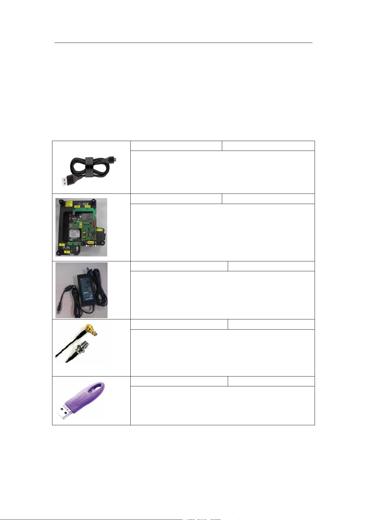
CA-101 Data Service Cable
This cable provides a connection from the USB port of the
personal computer or notebook to the micro USB connector of
the phone and allows Point of Sale (POS) locations to flash the
mobile terminal.
MJ-200 Module Jig
This jig allows PWB-level service and troubleshooting for
authorized service centers. It supports regulated and
unregulated DC input voltages, a headset jack for audio tests
and a RUIM card reader. It also supports simultaneous RF
connections to the CDMA engine.
N/A(Package with Module Jig) AC power adapter
This AC power adapter(has 5.50mm power cord connector) is
used to provide DC power to the mobile phone and service tools
(e.g. Module Jig) from power supply for CDMA tuning (packaged
with the module jig )
CA-128RS(10cm) RF Service Cable
This test cable is used for RF engine testing and tuning. It snaps
directly on the mobile terminal’s RF connector and converts the
output to a surface mounting assembly connector.
PK-86 AMS SW Protection Key
This hardware dongle connected to the USB port of the service
computer, enables the use of the service software. It is not
possible to use the service software without the dongle. This
dongle is used for service level 3.
Issue 1
Copyright © 2008 Nokia, All rights reserved
Page 4

1508(RM-430)
/
Service Tools Nokia Customer Care
2.2 L3 service configuration
The following diagram illustrates the service setup with Module Jig for Level 3 auto tuning
Test Equipment
(e.g. R&S CMU200, or
Agilent 8960)
RF Test Cable
GPIB Interface
Computer with
1508i Service
Software(PST tool)
L3 Dongle
Figure 1
GPIB
Serial
USB
Data Service Cable:
- USB, or
- Serial
PWB
1508i
Module Jig
MJ-200
Power Service Cable
External
Power Supply
/AC adapter
Issue 1
Copyright © 2008 Nokia, All rights reserved
Page 5

1508(RM-430)
Service Tools Nokia Customer Care
3 MJ-200 handling instructions
3.1 External connections &Switch instructions
1. Micro USB connector
2. S101 Power Key (turn power “on” when starting )
3. U52 banana connectors for current meter (0~1A)
4. S1 switch for current measurement
5. U51 banana connectors for back up power supply DC 3.7V~4.2V
6. Serial Port (connect 9 pin serial cable connect with PC for battery calibration and RF
calibration )
7. CN101 AC Power Supply connector (for AC adapter or power service cable 6.5V~7.5V.
1A)
8. S102 for main power and back up power switch
9. S2 Download/Test mode switch
(Turn “off” when using the module jig ,enter download mode by pressing and holding key
on keypad. )
10. UIM slot
Issue 1
Copyright © 2008 Nokia, All rights reserved
Page 6

1508(RM-430)
Service Tools Nokia Customer Care
3.2 MJ-200 PWB Pin definition
module jig pin
definition
Issue 1
Copyright © 2008 Nokia, All rights reserved
Page 7

1508(RM-430)
Service Tools Nokia Customer Care
3.3 Handling instruction:
1. Put the PWB onto the module jig.
2. Close the module jig up.
Issue 1
Copyright © 2008 Nokia, All rights reserved
Page 8

1508(RM-430)
Service Tools Nokia Customer Care
3.Module Jig connection
1) RF calibration/Battery calibration
Serial Cable provides a connection from the serial port of the personal computer or
notebook to the serial port on module jig. To perform the RF calibration Battery calibration
refer to
4. Power on sequence
1) S
2) S
3) S
4) S
5) The test can be started
Figure 1.
2) SW update / flashing
USB Cable CA-101 provides a connection from the USB port of the personal computer or
notebook to the micro USB connector on Module jig for SW update/flashing
3) Full Phone functionality in the jig
Press #0000# , select CIT test >Manual test to perform the phone functionality check.
Please set module jig as following:
@ VCC1 (Power Supply 1 :AC adapter or power service cable V
102
7.5V,I
1
101
=1A); S
max
@ on(power on )
@ On(main current ); S
@ VCC2(Power Supply 2)
102
@ Off (adding a current meter between two red banana
101
connectors U52 for current measurement)
@off (test mode)
2
cc1
:6.5V-
Issue 1
Copyright © 2008 Nokia, All rights reserved
Page 9

1508(RM-430)
Service Tools Nokia Customer Care
Issue 1
Copyright © 2008 Nokia, All rights reserved
 Loading...