

Page 1

1508(RM-430)
Service Software Instructions Nokia Customer Care
Nokia Customer Care
1508(RM-430)
Mobile Terminal
Service Software Instructions
Issue 1
Copyright © 2008 Nokia, All rights reserved
Page 2

1508(RM-430)
Service Software Instructions Nokia Customer Care
Table of contents
1. Software Summary............................................................................................................................. 3
1.1 Hardware, Operating system and environment request .............................................................. 3
1.2 Software utilization..................................................................................................................... 3
1.3 Installation .................................................................................................................................. 3
2. Use of AMS .......................................................................................................................................... 6
2.1 Download Mode..................................................................................................................... 9
2.1.1 Emergency Download............................................................................................. 9
2.2 General Mode....................................................................................................................... 13
2.2.1 Phone Information................................................................................................. 14
2.2.2 Display Capture ..................................................................................................... 15
2.2.3 Label Printing......................................................................................................... 19
2.2.4 Critical Data Backup.............................................................................................. 21
2.2.5 RF Calibration........................................................................................................ 22
2.2.6 DebugTool ............................................................................................................... 26
3. Setup communication........................................................................................................................ 30
4. Enter calibration mode...................................................................................................................... 31
5. PSN SFC read and writing................................................................................................... ............. 32
6. CDMA Battery Measurement Calibration................................................................................... 33
7. CDMA RxAGC Calibration............................................................................................................ 34
7.1. CDMA RxAGC Baseline...................................................................................................... 34
7.2. CDMA RxAGC Frequency Channel Adjustment ................................................................. 35
8. CDMA TxAGC Calibration ............................................................................................................ 37
8.1. CDMA TxAGC Baseline ...................................................................................................... 37
8.2. CDMA TxAGC Frequency Channel Adjustment.................................................................. 38
8.3. CDMA TxAGC Max Power Limit Frequency Adjustment................................................... 40
8.4. CDMA TxAGC Closed Loop RF Power............................................................................... 40
8.5. CDMA TxAGC Closed Loop Frequency Channel Adjustment............................................ 41
9. Error Code....................................................................................................................................... 44
9.1. three class error code ............................................................................................................ 44
9.2. Error Message Table ............................................................................................................. 44
Issue 1
Copyright © 2008 Nokia, All rights reserved
Page 3
1508(RM-430)
Service Software Instructions Nokia Customer Care
1. Software Summary
In order to understand the requests of operating device and driver for the software, the user should
read this chapter carefully before using Nokia 1508 AMS tool. Users can setup the PC according to
their own needs, in order to get the most out of the service software.
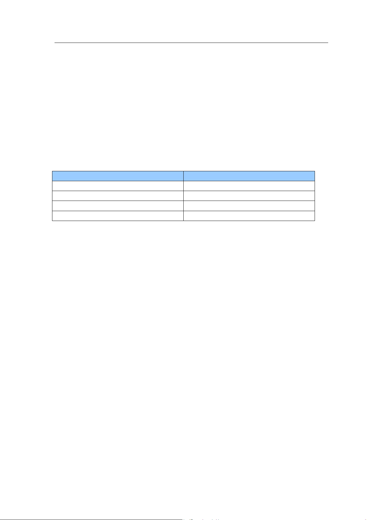
1.1 Hardware, Operating system and environment request
Table.1 shows the lowest request for Hardware configuration.
Operating system: windows 2000, windows XP
PC Minimum Requirement
Processor 700MHz
RAM 256MB
Required Disk space 100MB
Interface ports USB
Table.1 Lowest request for Hardware configuration
1.2 Software utilization
Insert Dongle.
AMS has two function modes: Download mode and General mode. When in download mode, the
handset must be working in this mode. When in general mode, the handset must be working in
power up mode. AMS tool will report Warning message if the two modes are used incorrectly.
Download mode comprises of one type: Emergency Download. General mode includes six types:
Phone Information, Display Capture, Label Print, Critical Data Backup, RF Calibration and RF Tool.
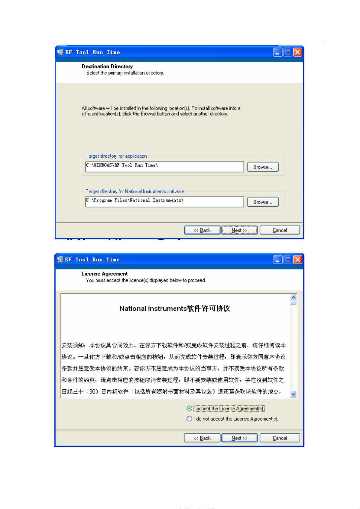
1.3 Installation
Please install the Nokia 1508 AMS tool as follows. It generally has three parts, where driver and RF
Tool Run Time must be installed separately. You can install the AMS software directly if the driver
and RF Tool Run Time are already installed.
Steps for installing RF Tool Run Time
1. Double click the setup.exe,
2. It will remind you to select the installation path. Click “next” to go on with the following steps.
Issue 1
Copyright © 2008 Nokia, All rights reserved
Page 4
1508(RM-430)
Service Software Instructions Nokia Customer Care
3. Select “I accept the License Agreement(s)”. Then click “Next”.
4. Click “Next”.
Issue 1
Copyright © 2008 Nokia, All rights reserved
Page 5
1508(RM-430)
Service Software Instructions Nokia Customer Care
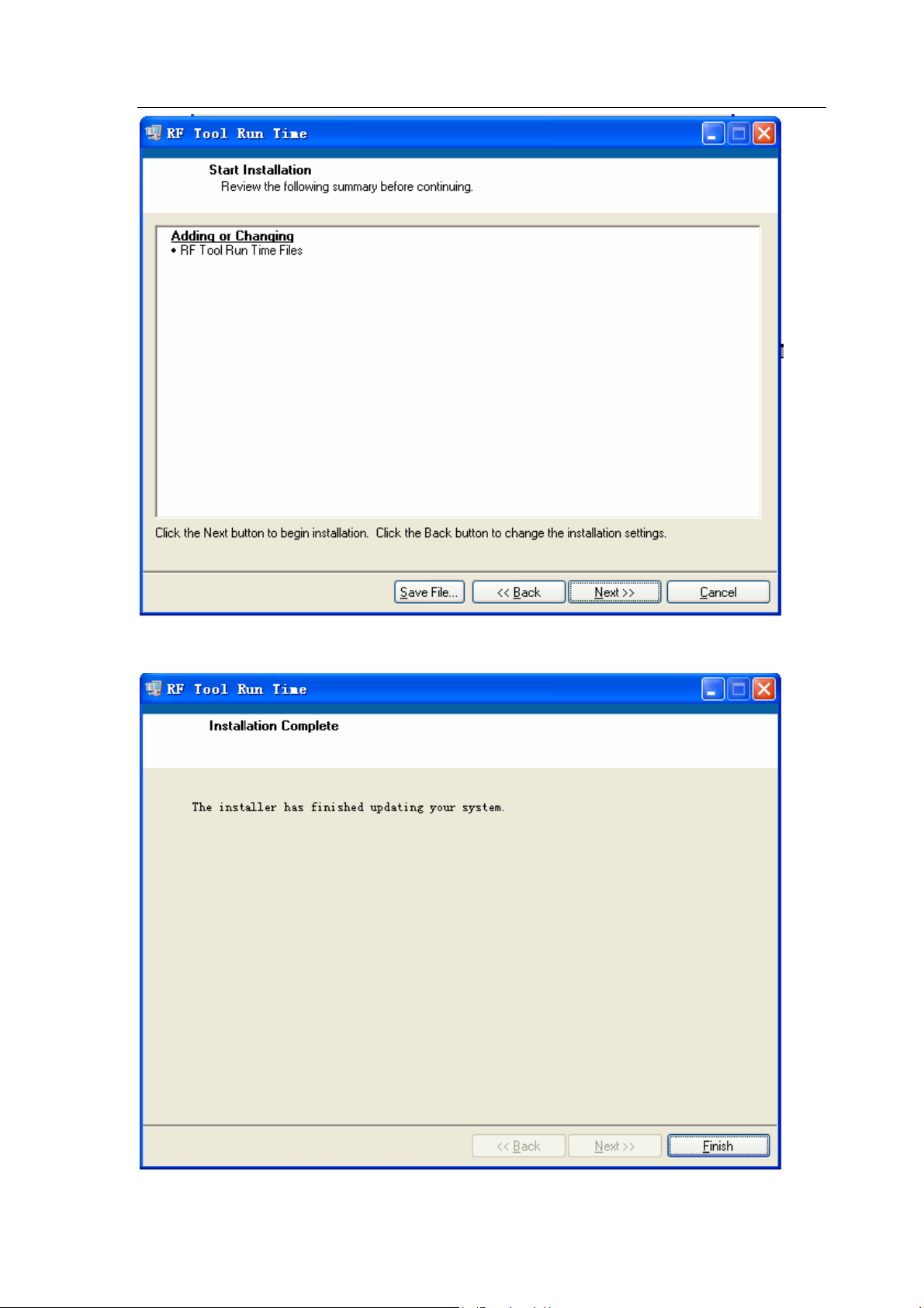
5. Click “finish” button to complete the installation.
Issue 1
Copyright © 2008 Nokia, All rights reserved
Page 6
1508(RM-430)
Service Software Instructions Nokia Customer Care
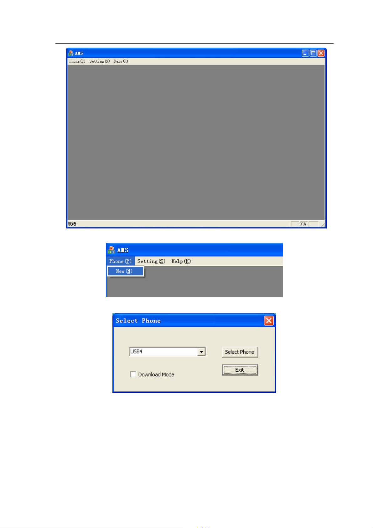
2. Use of AMS
There are three steps to use AMS tool: Firstly, choose Handset and Use mode; secondly, choose
the appropriate function; finally, do related operation with the help of manual.
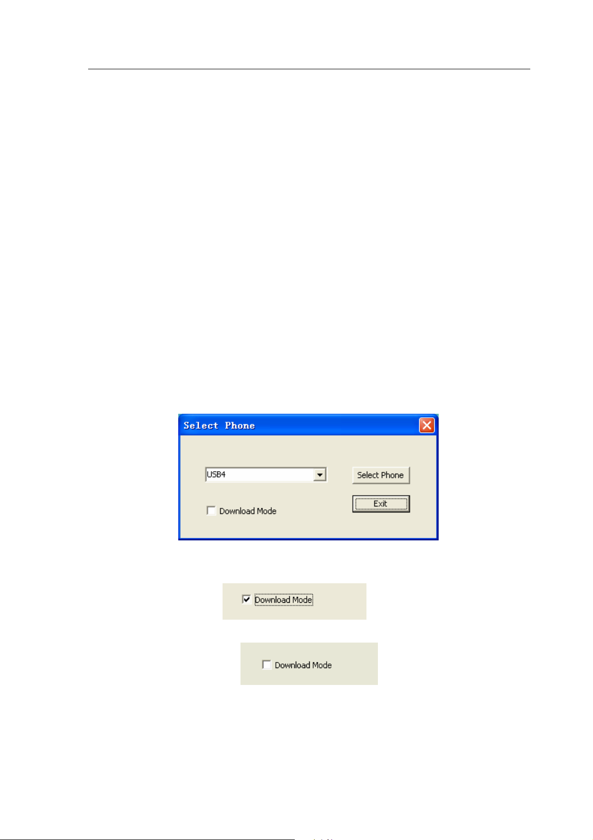
Select phone and use mode:
Note:
When using the download functions, please set the mobile phone in
download mode. The following are steps of entering download mode:
1. Resume power supply after the mobile phone is powered off.
2. Press “Mid key” for about 5 seconds till USB cable is connected between the
PC and the phone.
After the above actions are completed, you can use the download functions of
AMS.
1. Run AMS, pop up “Select Phone” dialogue box:
2. Select “Download Mode” option to enter download mode.
3. Deselect this option if you just want to use general mode.
4. Click the button “Select Phone”. The general mode shows as below.
Issue 1
Copyright © 2008 Nokia, All rights reserved
Page 7
1508(RM-430)
Service Software Instructions Nokia Customer Care
Download mode shows as below.
Select Phone: Activate “Select Phone” in the panel.
When dialogue box is closed, and if you want to use AMS tool, you can re-open the dialogue box in
panel.
Issue 1
Copyright © 2008 Nokia, All rights reserved
Page 8
1508(RM-430)
Service Software Instructions Nokia Customer Care
1. In main menu, select “Phone”.
2. Select the submenu “New” to open a new dialogue box.
Issue 1
Copyright © 2008 Nokia, All rights reserved
Page 9

1508(RM-430)
Service Software Instructions Nokia Customer Care
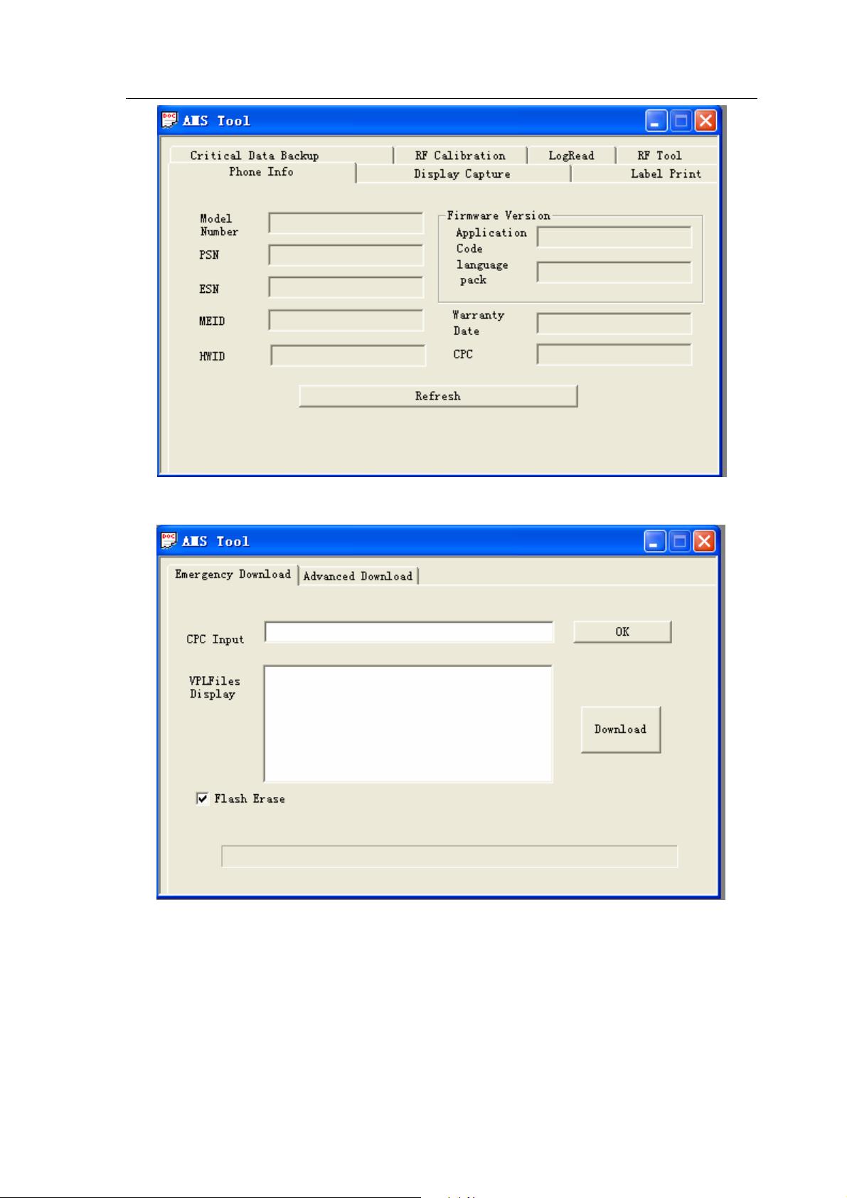
2.1 Download Mode
Download mode provides only one function, “Emergency Download”.
2.1.1 Emergency Download
Before using “Emergency Download”, you must install some packages in the local PC to support
the software download. This package contains all BIN files requested by mobile phone. Its file name
is composed by 5 parts.
For example:
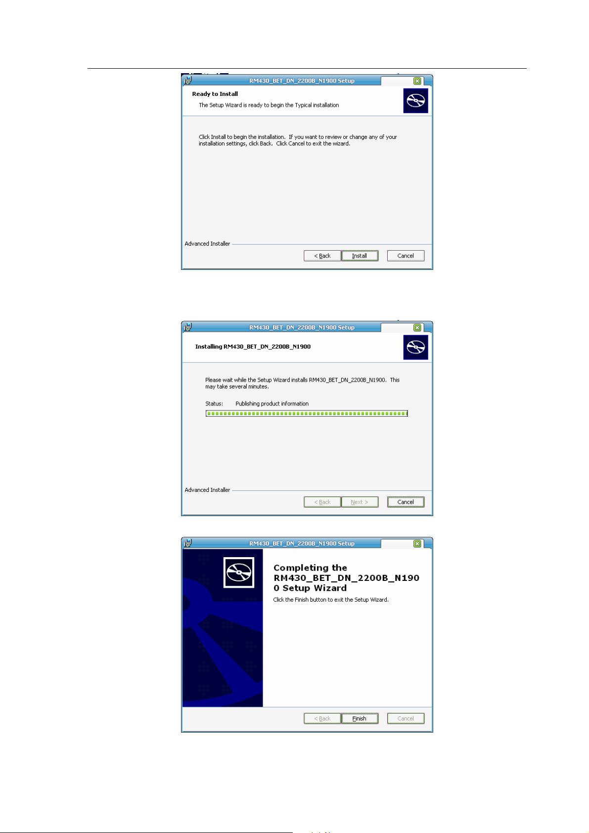
Steps for installing package:
1. Double-click the package you want to install. It displays as below:
RM430_BET_DN_2200B_N1900
Mode Type
Carrier
Version info
N: Non-RUIM
R: RUIM
1900 or 800: RF
2. Click the button “Next >”.
3. Click the button “Install” to start the installation.
Issue 1
Copyright © 2008 Nokia, All rights reserved
Page 10
1508(RM-430)
Service Software Instructions Nokia Customer Care
4. Installing…
5. Wait until the installation is finished.
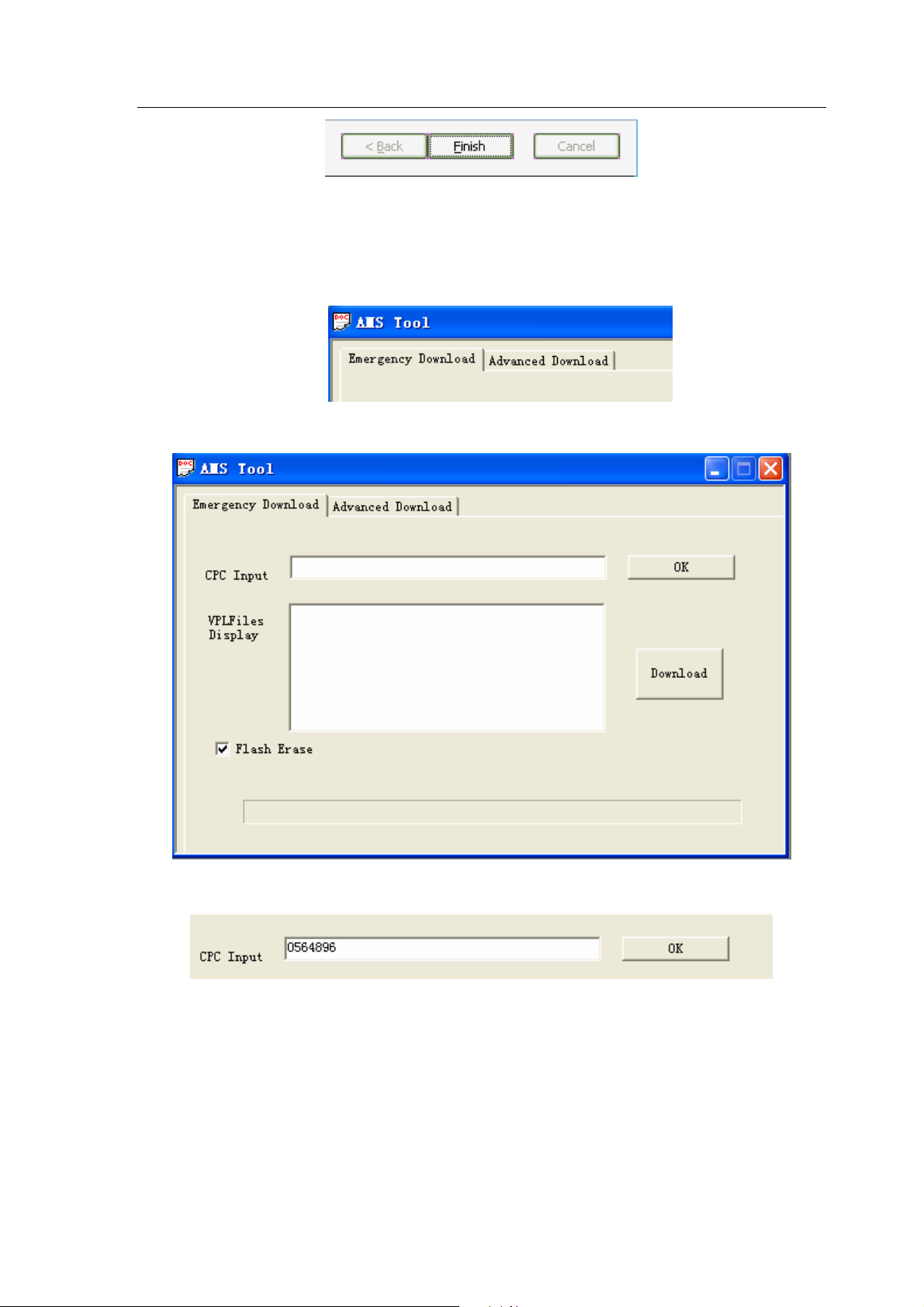
6. Click the button “Finish” to exit the installation.
Issue 1
Copyright © 2008 Nokia, All rights reserved
Page 11
1508(RM-430)
Service Software Instructions Nokia Customer Care
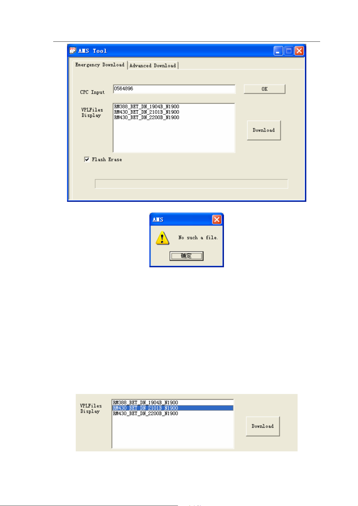
In “Emergency Download”, it is possible to search and display all suitable version files according to
the CPC code inputted by user. These version files are used for software download.
1. Click the tab to switch to “Emergency Download”.
2. It displays as below:
3. Input CPC code.
4. Click the button “OK”. A list of related version files will be displayed.
Issue 1
Copyright © 2008 Nokia, All rights reserved
Page 12
1508(RM-430)
Service Software Instructions Nokia Customer Care
NOTE
: If the warning dialog pops up, the reason may be one of the
following three:
1. You have input an incorrect CPC number.
2. You have not installed the appropriate package.
3. You have not registered msxmil4.dll file.
There are four steps to register msxmil4.dll file.
1. Install MSXML 4.0SP2_cn.msi.
2. Copy msxml4.dll and regist_msxml4_object.bat to the PC path where
AMS is installed.
3. Run regist_msxml4_object.bat by double click.
4. If it is registered successfully, restart AMS.
5. Select the version file you want to download.
Issue 1
Copyright © 2008 Nokia, All rights reserved
Page 13
1508(RM-430)
Service Software Instructions Nokia Customer Care
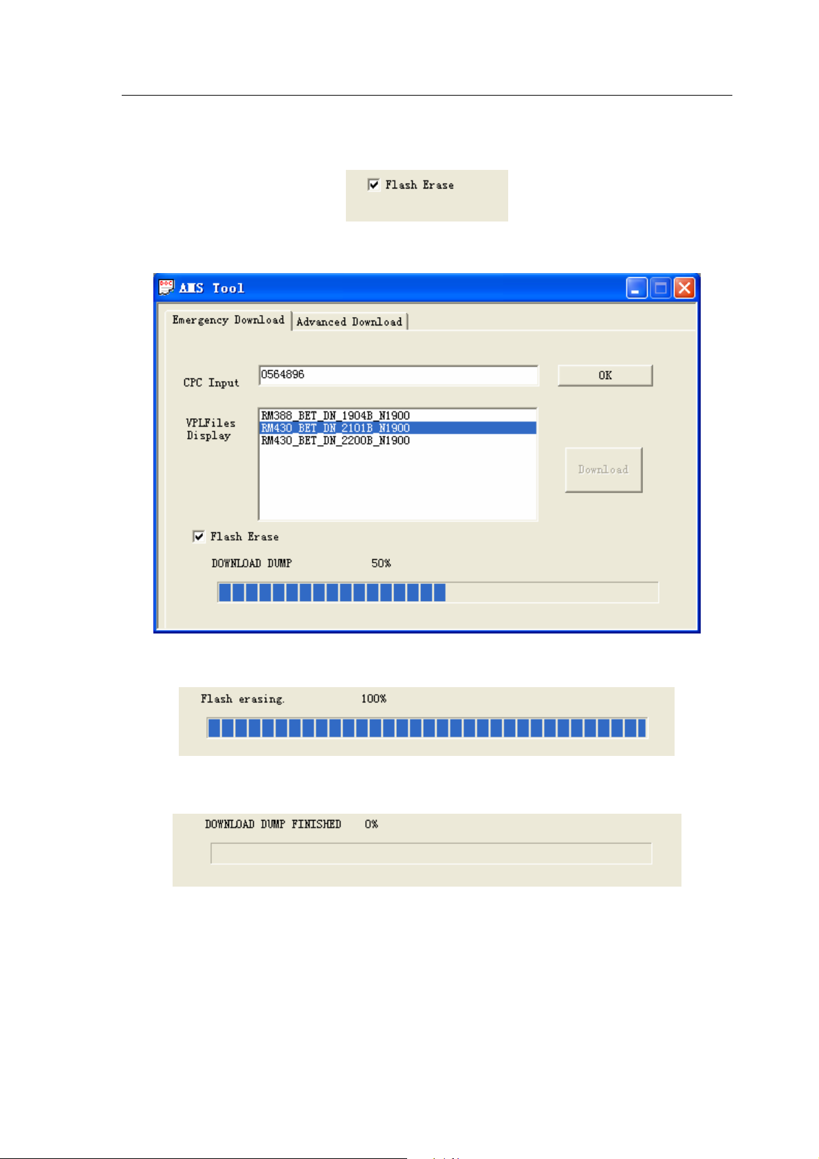
6. The option “Flash Erase” is selected by default. If you don’t need to erase FSM data, you can
deselect this option (it is not recommended to modify the default setup except software
developers).
7. Click the button “Download” to start download.
8. Wait until the download is finished.
9. Download is finished.
2.2 General Mode
The General Mode provides five different functions, including “Phone Information”, “Display
Capture”, “Label Printing”, “Critical Data Backup” and “RF Calibration”. Before using this mode, the
handset must be in Power Up status.
Issue 1
Copyright © 2008 Nokia, All rights reserved
Page 14
1508(RM-430)
Service Software Instructions Nokia Customer Care
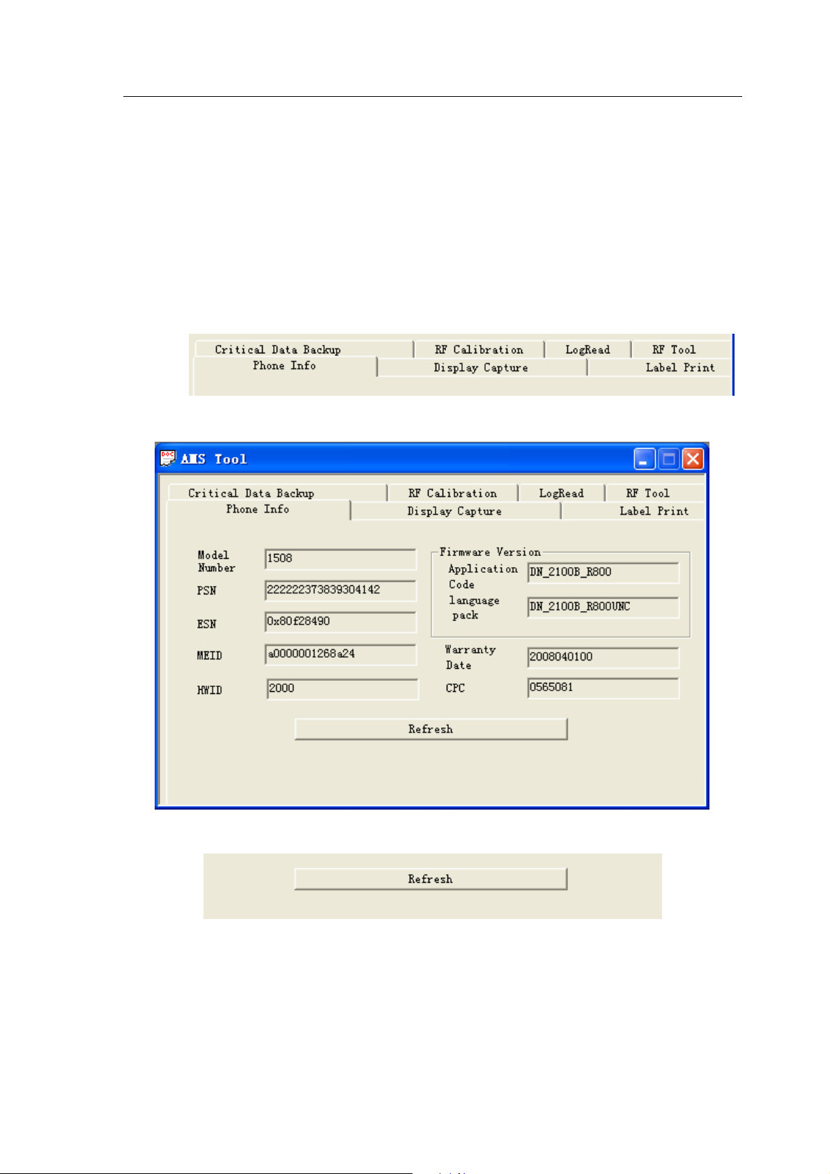
2.2.1 Phone Information
When getting into General mode, the default is Phone Information, which can read out nine
parameters from the handset and display them on the screen.
The nine parameters are Module Number, PSN, ESN, MEID, HWID, Application Code, Language
Pack, Warranty Data and CPC.
1. Switch to “Phone Information”.
2. It displays as below:
3. Click button “Refresh” to refresh the current data parameters.
4. Refresh is finished.
Issue 1
Copyright © 2008 Nokia, All rights reserved
Page 15
1508(RM-430)
Service Software Instructions Nokia Customer Care
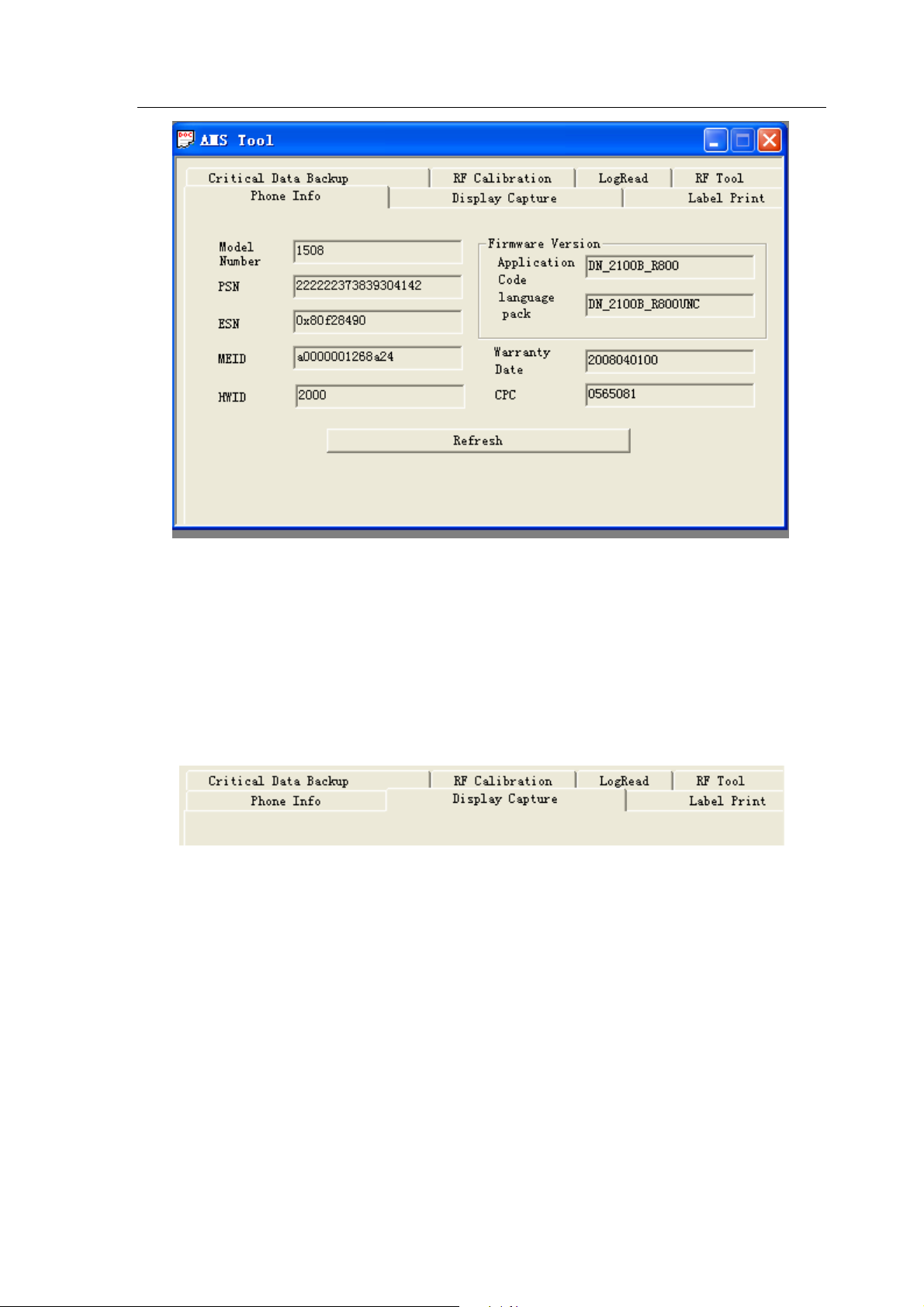
2.2.2 Display Capture
Display Capture is used to capture the screen of the handset and then choose the path to save.
The file can be saved as BMP, JPG and PNG formats.
1. Switch to Display Capture.
2. It displays as below:
Issue 1
Copyright © 2008 Nokia, All rights reserved
Page 16

1508(RM-430)
Service Software Instructions Nokia Customer Care
3. Click the button “Begin To Capture” and a box “SnapShot” appears as below:
4. Click the button “Connect”.
5. It displays a connection successful message in dialogue box.
Issue 1
Copyright © 2008 Nokia, All rights reserved
Page 17

1508(RM-430)
Service Software Instructions Nokia Customer Care
6. Click the button “GetImage” to capture the current screen.
7. Click “Option”.
8. In Option, modify the directory to save the image.
9. Click “Browse”.
Issue 1
Copyright © 2008 Nokia, All rights reserved
Page 18

1508(RM-430)
Service Software Instructions Nokia Customer Care
10. Choose the save directory.
11. Click the button “OK” (the left button) to confirm, the save directory is modified and saved.
12. Switch back to “Main”.
13. Choose image format.
14. Click the button “SaveImage” to save the image.
Notice:
When Display Capture is in use, the other AMS functions are disabled.
Issue 1
Copyright © 2008 Nokia, All rights reserved
Page 19

1508(RM-430)
Service Software Instructions Nokia Customer Care
2.2.3 Label Printing
Label Printing is used to print out the product label. Read out the data from the handset and
transfer into printing file to print it out. Set up the printer before label printing.
Note: Please make sure you have installed RF Tool Run Time before you using label printing.
Set up the printer before label printing.
C
Select Start->
Click “right” button to chose the general/text only printer as the default printer.
ontrol panel->Printer and fax on your PC.
1. Switch to “Label Printing”.
2. It displays as below:
Issue 1
Copyright © 2008 Nokia, All rights reserved
Page 20

1508(RM-430)
Service Software Instructions Nokia Customer Care
3. Click “Refresh”.
4. Read out data and transfer into printin g file.
5. Click “print” to start printing.
Copyright © 2008 Nokia, All rights reserved
Issue 1
Page 21

1508(RM-430)
Service Software Instructions Nokia Customer Care
2.2.4 Critical Data Backup
Critical Data Backup is used to backup the data, i.e. RF parameters.
1.
Switch to RF Backup.
2.
It displays as below:
3.
Click “Critical Data Backup” to start backup. The button is disabled.
Issue 1
Copyright © 2008 Nokia, All rights reserved
Page 22

1508(RM-430)
Service Software Instructions Nokia Customer Care
4.
Five seconds later, the backup is finished. The button is enabled again.
2.2.5 RF Calibration
RFcalibrationisatool forautomaticallytuning theRFvaluesoftarget, and automatically
testtheRFperformance.
Issue 1
Copyright © 2008 Nokia, All rights reserved
Page 23

1508(RM-430)
Service Software Instructions Nokia Customer Care
1. Click on the middle button of RF Calibration tab.
2. RF Calibration screen:
2.1. Log Display Frame
Log Display: calibration information.
2.2. Control Setting Frame.
Copyright © 2008 Nokia, All rights reserved
Issue 1
Page 24

1508(RM-430)
Service Software Instructions Nokia Customer Care
●
Text Window: Show test result.
●
Band Select: Switch band.
●
Select Action: Calibration or Test.
●
Select Function: Enable save Log, Enable Detail UI information and enable Mo call mode.
●
Test Set info: Show test set which program auto detected.
3. Program Setting
Config>>Setting
●
GPIB setting: Set GPIB card Number, Callbox Address, and Power Supply Address.
●
Phone: Set communicate type.
Issue 1
Copyright © 2008 Nokia, All rights reserved
Page 25

1508(RM-430)
Service Software Instructions Nokia Customer Care
●
Cable Loss: Set cable loss of testing band.
4. Call Config
Config>>Call Config
Config the parameter when establishing a call, and test.
5. Start Test
Click on the Start button to Setup calibration or test.
Final result will be shown on Text Window.
Click on the Stop button to stop calibration or test on current step.
6. Battery Calibration
In battery Calibration, Config>>Power supply Control and set Communicate port as serial port.
Otherwise the Else battery Calibration value will write default value.
Program support power supply Type:
Agilent E3631, Agilent 66319, Agilent 66309, Agilent 66311, Agilent 66312, Kethley 2306,
Kethley 2304, Kethley 2303, Kethley 2302.
7. RF Calibration & Performance test
Program support Callbox Type:
Agilent 8960, R&S CMU200.
Issue 1
Copyright © 2008 Nokia, All rights reserved
Page 26

1508(RM-430)
Service Software Instructions Nokia Customer Care
8. Error Code
Use Error Translate tool to explain the cause of a failed test.
Enter the Error code in Error Code String window, click on OK button. The detailed error
information will show Text window. For example, Error code: 17815, can Translate as shown below:
2.2.6 DebugTool
2.2.6.1. DebugTool overview
The DebugTool is used for online debugging and repair analysis.
Main screen.
Issue 1
Copyright © 2008 Nokia, All rights reserved
Page 27

1508(RM-430)
Service Software Instructions Nokia Customer Care
There are several function areas in main screen. There are 3 buttons, including an
error code translate tool button, a configure setting button and a quit program
button. A text message box shows the command sent out and received.
2.2.6.2 Config and Error code Translate
2.2.6.2.1. Config
Config setting panel can set com port type (USB or Serial), com port number, and
baud rate.
2.2.6.2.2. Error code Translate
Enter the error code in Error Code text box, then click on ok button. Error code will
be Translated in the message window.
Issue 1
Copyright © 2008 Nokia, All rights reserved
Page 28

1508(RM-430)
Service Software Instructions Nokia Customer Care
2.2.6.3. Log
Debugtool creates a log file after the Via hub Setup. All the operations on the main
panel will be recorded in this log. The log is stored in the folder in local dir of
program.
A sample log is shown as below. This file is named by create time.
2.2.6.4. Text Info
All operations are displayed in this window.
Issue 1
Copyright © 2008 Nokia, All rights reserved
Page 29

1508(RM-430)
Service Software Instructions Nokia Customer Care
Issue 1
Copyright © 2008 Nokia, All rights reserved
Page 30

1508(RM-430)
Service Software Instructions Nokia Customer Care
3. Setup communication
3.1. Setup Hub for communication. All the buttons are dimmed when the program
is open. To activate the button and setup soft hub, first click on the Setup Hub
button.
Then wait for the button to be activated.
3.2. Release hub can disconnect the communication. Then all the buttons are
deactivated.
Issue 1
Copyright © 2008 Nokia, All rights reserved
Page 31

1508(RM-430)
Service Software Instructions Nokia Customer Care
4. Enter calibration mode
All BB and RF calibration must be done in calibration mode. This mode can be
entered when phone is switched on and in boot waiting time (only 1.5s).This mode
can also be entered when the power is already on.
In this chapter, use the Initial frame.
4.1. Enter when phone on.
A. Start with power supply power down.
B. Click on the Boot To Loader button.
C. Power on. Wait for phone to stop on boot.
D. Click on the Enter Cal Mode button.
E. Click on the Jump Loader button. Then wait for 3s to 5s, the phone is in the
calibration mode.
4.2. Enter after phone on.
A. Start with power supply power on until the phone is fully on.
B. Click on the Jump Loader button.
D. Click on the Enter Cal Mode button.
E. Click on the Jump Loader button. Then wait for 3s to 5s, the phone is in the
calibration mode.
Issue 1
Copyright © 2008 Nokia, All rights reserved
Page 32

1508(RM-430)
Service Software Instructions Nokia Customer Care
5. PSN SFC read and writing
PSN is the product serial number. SFC is the keyword for MES.
In this chapter, use the Process frame.
Issue 1
Copyright © 2008 Nokia, All rights reserved
Page 33

1508(RM-430)
Service Software Instructions Nokia Customer Care
6. CDMA Battery Measurement Calibration
6.1. Calibration method
Select some groups of voltage value, switch them to corresponding Aux ADC
values and write them into memory. Calibration steps: Select 5 groups of voltage
value, switch them to 5 groups of Aux ADC numerical value via AD.
6.2. Calibration Procedure
A. Start with reset system (PS power down, reset).
B. Set the power supply to the desired value.
C. Get the Aux ADC Value from the Debug Tool. The battery AUX ADC detect
channel is 1, the on/off status is on. Click on the Get Result button to get ADC
value.
D. Try more then 5 times. Get the average value. Store the power supply voltage
point versus the Aux ADC value.
E. Iterate steps B - D once for another power supply voltage.
Issue 1
Copyright © 2008 Nokia, All rights reserved
Page 34

1508(RM-430)
Service Software Instructions Nokia Customer Care
7. CDMA RxAGC Calibration
Supported receiver calibration items are the following:
CP DB HWD PCS RxAGC
CP DB HWD PCS RxAGC Freq Chan Adj
Note: Before starting the RxAGC Calibration, the Rx date must be set empty,
otherwise the calibrate value may not be correct.
7.1. CDMA RxAGC Baseline
7.1.1. CDMA RxAGC Baseline overview
The basic mechanism for calibration is to provide a signal of known power at the
antenna, allow the RxAGC to settle, and make note of the resultant RxAGC PDM
value. In this way, the “settled” value of the PDM for a given Rx power is known..
7.1.2. Calibration Procedure
A. Start with reset system (PS power down, reset).
B. Click on CP Enable/Disable and CP Power Down/Up. Let the CP disable and
power down.
C. Set the channel. Set the control mode to Manual, and the band to the target
band.
D. Set the test set frequency channel to the test frequency. For the first data point,
enter the channel used to calibrate the Rx AGC. Then set the test set transmission
power to a desired power which is in the Rx highest gain. The Reference Level is 99dB.
E. Initialize the calibration RxAGC gain state by clicking on DSPM Rfc Dagc, Set
gain state to highest gain.
F. Click on DSPM Spy Enable/Disable.
Issue 1
Copyright © 2008 Nokia, All rights reserved
Page 35

1508(RM-430)
Service Software Instructions Nokia Customer Care
The Spy windows become active, and display the current Tx and Rx status.
G. Get the RxDAgc Value Bitsel and the RxDAgc Value Gain. Write those
calibration parameters together with Reference Level to the non-volatile area of
flash memory. To confirm the new calibration, first update the Flash by either
power cycling the UUT or by using the CalMode Select with the NVRAM option.
H. Calibrate the Gain offset. Set the test set transmission power to the desired
power which is between the switch point of each gain level. Calibrate the gain level
from the high gain to low gain.Set the calibration RxAGC gain state by clicking on
DSPM Rfc Dagc.
I. Get the received power form the Spy window. For example, if the BS power is 85dBm, and the gain state is 3, we get -96dBm from spy window. The offset of
gain 4 to gain 3 is -85 – (-96) = 11dBm. Write the calibration parameters to the
non-volatile area of flash memory. Confirm the new calibration result.
J. Iterate steps H - I for all desired calibration points.
7.2. CDMA RxAGC Frequency Channel Adjustment
7.2.1. About CDMA RxAGC Frequency Channel Adjustment
This procedure is performed at only one power setting. This procedure assumes
that the baseline RxAGC calibration table has been loaded into NVRAM. However,
if the calibration application (running on a PC) stores the RxAGC tables from
Section 7.2.1 in PC memory, then the PC Application can interpolate dBm power
values from the PDM value returned by Debugtool. More details are provided
below in steps below.
Issue 1
Copyright © 2008 Nokia, All rights reserved
Page 36

1508(RM-430)
Service Software Instructions Nokia Customer Care
7.2.2. CDMA RxAGC Frequency Channel Adjustment Procedure
A. Perform the procedure at “nominal” or room temperature.
B. The baseline RxAGC calibration must have already been completed.
C. The RxAGC frequency channel adjustment, and temperature adjustment
tables must be zeroed.
D. Connect the antenna to CDMA test set.
E. Reset the UUT, start Debugtool, and do not press the Power key on the Virt
MMI (i.e., PS should be off and LID reset). Send the message CP Enable, with
Disable option.
F. Set the test set Transmission Power to a desired power point (-100 dBm is a
suggested value). This is normally a point that is calibrated during Rx AGC
calibration.
G. Set the test set frequency channel to the test frequency. For the first data
point, enter the channel used to calibrate the RX AGC.
H. Set the frequency channel to the calibration frequency using the CP PLL
Channel Config. For the first data point, enter the channel used to calibrate the RX
AGC. Set the Control mode as Manual, the band to target band.
I. Allow for 25 ms (or more) of settle time.
J. Get the RxAGC Antenna Power (dBm) value using the DSPM Rx AGC Get
Parms. As show in the picture, we get received power -101.1dBm.
K. Calculate Error Power = Transmission Power – Antenna Power, where the
Transmission Power was set in step F and the Antenna Power was obtained in
step J. Store the Error Power (dB) versus the frequency channel point in the nonvolatile area of flash memory.
L. Iterate steps G - K for all desired calibration points.
Issue 1
Copyright © 2008 Nokia, All rights reserved
Page 37

1508(RM-430)
Service Software Instructions Nokia Customer Care
8. CDMA TxAGC Calibration
There are multiple tables for calibration of the transmitter. All curves must be
generated for all band classes and for all Tx hysteresis states that are utilized.
Supported Transmitter calibration items are the following:
●
CP DB HWD PCS TxAGC
●
CP DB HWD PCS TxAGC Freq Chan Adj
●
CP DB HWD PCS Tx Limit Freq Chan Adj
●
CP DB HWD PCS Tx Power Detect
●
CP DB HWD PCS Tx Power Detect Freq Chan Adj
8.1. CDMA TxAGC Baseline
8.1.1. CDMA TxAGC Baseline overview
The basic mechanism of the calibration is to transmit a signal at the antenna port
with a certain PDM setting, the power of which is measured by a power meter,
spectrum analyzer, or CDMA test set. The PDM setting and resulting power are
then recorded. Care should be taken to provide enough calibration points near
maximum power to ensure accurate transmission power at this level.
8.1.2. CDMA TxAGC Baseline Procedure
A. Perform the procedure at “nominal” or room temperature.
B. The baseline RxAGC calibration must have already been completed.
C. The RxAGC frequency channel adjustment, and temperature adjustment
tables must be zeroed.
D. Connect the antenna to CDMA test set.
E. Reset the UUT, start Debugtool, and do not press the Power key on the Virt
MMI (i.e., PS should be off and LID reset). Send the message CP Enable, with
Disable option.
F. Set the frequency channel to the calibration frequency using the PLL Channel
Config. This is the baseline frequency, since the frequency compensation table is
not active. Set the Control mode as Manual, the band to target band.
G. Initialize the TxAGC PDM (HW Val in the box below) with a suitably low known
value, to prevent a potential surge of Tx power when the transmitter is turned on in
Issue 1
Copyright © 2008 Nokia, All rights reserved
Page 38

1508(RM-430)
Service Software Instructions Nokia Customer Care
the next step. Use the DSPM Tx AGC Config. Set the Mode as Manual, the
Method as HW_Value, the Hyst as current state.
H. Turn on the transmitter using the Tx Rate. Set the Rate is Tr Full Rate.
I. Set up the spectrum analyzer or test set to measure the channel power on the
same channel selected in step F.
J. Vary the HW Val until the reported power is within +/-1 dB of the desired power
level using DSPM Tx AGC Config.
K. Store the reported test set channel power (dBm) versus PDM value point in
the non-volatile area of flash memory.
L. Iterate steps G to K for all desired calibration points and Write to store the
values.
M. Repeat steps G – L for all desired gain points.
8.2. CDMA TxAGC Frequency Channel Adjustment
8.2.1. CDMA TxAGC Frequency Channel Adjustment overview
To perform this calibration, the baseline Tx AGC calibration should have already
been performed. This is performed for all gain states.
8.2.2. CDMA TxAGC Frequency Channel Adjustment Procedure
A. Perform the procedure at “nominal” or room temperature.
B. The baseline RxAGC calibration must have already been completed.
C. The RxAGC frequency channel adjustment, and temperature adjustment
tables must be zeroed.
D. Connect the antenna to CDMA test set.
E. Reset the UUT, start Debugtool, and do not press the Power key on the Virt
MMI (i.e., PS should be off and LID reset). Send the message CP Enable, with
Disable option.
Issue 1
Copyright © 2008 Nokia, All rights reserved
Page 39

1508(RM-430)
Service Software Instructions Nokia Customer Care
F. Turn off the transmitter test using the Tx Rate Test with the rate set to Tr Full
Rate.
G. Set the frequency channel to the channel used for calibrating the TX AGC
using the PLL Channel Config. CP PLL Channel Config Settings, Ctrl Mode:
Manual, Band: Band being calibrated, Channel: Channel being calibrated.
H. Set the measurement equipment to the frequency channel used for calibrating
the TX AGC (see step F).
I. Turn on the transmitter test using the Tx Rate Test with the rate set to Tr Full
Rate.
J. Set the Tx power by direct control of the dBm setting using TxAGC Config.
DSPM Tx AGC Config Settings, Ctrl Mode: Manual, Method: dB Gain, HW Val: N/A,
Hyst State: N/A, Power (dBm): Middle of band being calibrated (This is the Target
Tx Power).
K. Get the Measured Tx Power from the CDMA test set or other measuring
device and calculate:
Antenna Power Error = Target Tx Power - Measured Tx Power
L. Store the Antenna Power Error (dB) versus frequency channel point in the
non-volatile area of flash memory.
M. Iterate steps F to L for all desired calibration points and Write to store the
values.
N. Repeat steps F – M for all desired gain points.
Issue 1
Copyright © 2008 Nokia, All rights reserved
Page 40

1508(RM-430)
Service Software Instructions Nokia Customer Care
8.3. CDMA TxAGC Max Power Limit Frequency Adjustment
8.3.1. CDMA TxAGC Max Power Limit Frequency Adjustment overview
In order to perform this calibration, the other Tx AGC calibrations should have
already been performed. This procedure is performed for only one gain state, the
highest gain stage, since this table only applies to max power.
8.3.2. CDMA TxAGC Max Power Limit Frequency Adjustment procedure
A. Baseline TxAGC calibration tables must be loaded.
B. The Tx Limit Freq Chan Adj table must be cleared (write zeros in the DBM
template).
C. This procedure is identical to the procedure described in section 8.2., but must
be performed at the Max Power Level.
D. Write calibration parameters to the non-volatile area of flash memory .
8.4. CDMA TxAGC Closed Loop RF Power
8.4.1. CDMA TxAGC Closed Loop RF Power overview
The procedure for baseline, temperature adjustment and frequency channel
adjustment is the same as that for calibration of the dBm to PDM value tables as
described in Sections 8.1., 8.2., and 8.3., except that the Tx power detection ADC
should be read using Aux ADC Get.
8.4.2. CDMA TxAGC Closed Loop RF Power Procedure.
A. Perform the procedure at “nominal” or room temperature.
B. The baseline RxAGC calibration must have already been completed.
C. The RxAGC frequency channel adjustment, and temperature adjustment
tables must be zeroed.
D. Connect the antenna to CDMA test set.
E. Reset the UUT, start Debugtool, and do not press the Power key on the Virt
MMI (i.e., PS should be off and LID reset). Send the message CP Enable, with
Disable option.
F. Set the measurement equipment to the frequency channel used for calibrating
the TX AGC
G. Turn off the transmitter test using the Tx Rate Test with the rate set to Tr Full
Rate.
H. Set the frequency channel to the channel used for calibrating the TX AGC
using the PLL Channel Config. CP PLL Channel Config Settings, Ctrl Mode:
Issue 1
Copyright © 2008 Nokia, All rights reserved
Page 41

1508(RM-430)
Service Software Instructions Nokia Customer Care
Manual ,Band: Band being calibrated , Channel: Channel being calibrated. (see
step F).
I. Turn on the transmitter test using the Tx Rate with the rate set to Tr Full Rate.
J. Set the Tx power by direct control of the dBm setting using DSPM TxAGC
Config. Vary the HW Val until the reported power is within +/-1 dB of the desired
power level using DSPM Tx AGC Config. DSPM Tx AGC Config Settings, Ctrl
Mode: Manual, Method: dB Gain ,HW Val: N/A, Hyst State: N/A, Power (dBm):
Some starting value
K. Send the Aux ADC Get, a number of times (10 is good) and take the average.
CP AUX ADC Get Settings, AUX ADC Channel: Design specific, Tx PCG Sync: On.
K. Iterate steps J to K for all desired calibration points and Write to store the
values.
8.5. CDMA TxAGC Closed Loop Frequency Channel
Adjustment
8.5.1. CDMA TxAGC Closed Loop Frequency Channel Adjustment overview
In order to perform this calibration, the baseline Tx AGC calibration should have
already been performed. This is performed for only one gain state.
Issue 1
Copyright © 2008 Nokia, All rights reserved
Page 42

1508(RM-430)
Service Software Instructions Nokia Customer Care
8.5.2. CDMA TxAGC Closed Loop Frequency Channel Adjustment
Procedure
A. Perform the procedure at “nominal” or room temperature.
B. The baseline RxAGC calibration must have already been completed.
C. The RxAGC frequency channel adjustment, and temperature adjustment
tables must be zeroed.
D. Connect the antenna to CDMA test set.
E. Reset the UUT, start Debugtool, and do not press the Power key on the Virt
MMI (i.e., PS should be off and LID reset). Send the message CP Enable, with
Disable option.
F. Turn off the transmitter test using the Tx Rate Test with the rate set to Tr Full
Rate.
G. Set the frequency channel to the calibration frequency using PLL Channel
Config. This is the baseline frequency, since the frequency compensation table is
not active.
H. Set the frequency channel to the channel used for calibrating the TX AGC
using the PLL Channel Config. CP PLL Channel Config Settings, Ctrl Mode:
Manual ,Band: Band being calibrated , Channel: Channel being calibrated.
I. Turn on the transmitter test using the Tx Rate with the rate set to Tr Full Rate.
J. Set the Target Tx Power by direct control of the dBm setting using DSPM
TxAGC Config. Vary the HW Val until the reported power is within +/-1 dB of the
desired power level using DSPM Tx AGC Config. DSPM Tx AGC Config Settings,
Ctrl Mode: Manual, Method: dB Gain ,HW Val: N/A, Hyst State: N/A, Power
(dBm): Some starting value
Issue 1
Copyright © 2008 Nokia, All rights reserved
Page 43

1508(RM-430)
Service Software Instructions Nokia Customer Care
K. Set the measurement equipment to the measurement frequency channel.
L. Get the Measured Tx Power (over the 1.25 MHz bandwidth) from the CDMA
test set (or other
measuring device) and get the Closed Loop Tx Power from the Current Tx Power.
The true power calculate: Read Power / 64 = True Power (dB)
M. Calculate Power Error = Measured Tx Power - Closed Loop Tx Power .
N. Store the Power Error (dB) versus frequency channel point.
O. Iterate steps 7, 10-12 for all desired calibration points.
P. Write calibration parameters to the non-volatile area of flash memory
Issue 1
Copyright © 2008 Nokia, All rights reserved
Page 44

1508(RM-430)
Service Software Instructions Nokia Customer Care
9. Error Code
9.1. three class error code
Use Error Translate tool to help explain the cause of a failed test.
Enter the Error code in Error Code Stringwindow, click on OK button. The detailed
error information will show in the Textwindow below. For example, Error code:
17815, can Translate as shown.
9.2. Error Message Table
[Error_Class_3]
1000 INIT_SetUp_ETSCOMPort_ERROR
3000 INIT_ModeSetting_ERROR
2000 Check_CPSWHWVersion_Compare_ERROR
4000 Check_CheckProcessBit_ERROR
5000 Check_BandSelect_ERROR
6000 Check_EndProcess_ERROR
7000 Cal_InitValue_ERROR
23000 Process_CheckBit_ERROR
Issue 1
Copyright © 2008 Nokia, All rights reserved
Process control Error
Page 45

1508(RM-430)
Service Software Instructions Nokia Customer Care
8000 Cal_TxAGCBaseCal_ERROR
9000 Cal_RxAGCBaseCal_ERROR
10000 Cal_TxAGCFREQCHAN_ERROR
11000 Cal_RxAGCFREQCHAN_ERROR
12000 Cal_TxAGCLIMFREQCHAN_ERROR
13000 Cal_TxAGCCLOSEDRFPWR_ERROR
14000 Cal_TxAGCCLOSEDFREQCHAN_ERROR
15000 Cal_WriteTemperatureDB_ERROR
16000 Cal_WriteBatteryDB_ERROR
17000 Cal_HWDBatteryCal_ERROR
18000 PTest_SetupCall_ERROR
19000 PTest_CallInitial_ERROR
20000 PTest_CallBandInitial_ERROR
21000 PTest_CallConnectFunction_ERROR
22000 PTest_QuickPerformanceTest_ERROR
39000 Loopback_Call_ERROR
[Error_Class_2]
390 INSTR_INSTRUMENTNULL_ERROR
400 INSTR_SETUP8960_ERROR
410 INSTR_SETCABLELOSS_ERROR
420 INSTR_WRITESECAPWR_ERROR
430 INSTR_SETONOFFSECAPER_ERROR
440 INSTR_WRITERFCHANNEL_ERROR
450 INSTR_SETUPTESTSET_ERROR
460 INSTR_RFPORTSET_ERROR
470 INSTR_SETIM2_ERROR
480 INSTR_SETOPERATINGMODE_ERROR
490 INSTR_SETITC_ERROR
500 INSTR_GETCURRPER_ERROR
510 INSTR_SETTXDYNAMIC_ERROR
520 INSTR_SETTXDYNAMICINIT_ERROR
530 INSTR_RESTORETXDYNAMIC_ERROR
540 INSTR_MEASTXDYNAMIC_ERROR
550 INSTR_RESETTESTSET_ERROR
560 INSTR_QUERYFSTATUS_ERROR
570 INSTR_PRINTFFATATUS_ERROR
580 INSTR_SETMEASSPEED_ERROR
590 INSTR_SWITCHPOWER_ERROR
600 INSTR_SETVOLTAGECURRENT_ERROR
610 INSTR_READCURRENT_ERROR
620 INSTR_SINGLECHIPCOMMUNICATE_ERROR
810 INSTR_Callbox_Initial_ERROR
820 INSTR_PowerSupply_Initial_ERROR
Calibration Error
Performance Test
Error
Instrument
Communicate Error
Issue 1
Copyright © 2008 Nokia, All rights reserved
Page 46

1508(RM-430)
Service Software Instructions Nokia Customer Care
830 INSTR_GPIBCard_ERROR
20 ETSCommand_Get_BootToLoader_ERROR
30 ETSCommand_EnterCalbrationMode_ERROR
40 ETSCommand_JumoToLoader_ERROR
50 ETSCommand_Loopback_ERROR
60 ETSCommand_CPOff_ERROR
70 ETSCommand_PowerDown_ERROR
80 ETSCommand_SNReadWrite_ERROR
90 ETSCommand_ProcessBit_RW_ERROR
100 ETSCommand_TestSWVersion_RW_ERROR
110 ETSCommand_CPSWHWVersionRead_ERROR
120 ETSCommand_DBFlush_ERROR
130 ETSCommand_RFBackup_ERROR
140 ETSCommand_DBClear_ERROR
150 ETSCommand_InitialNVRAM_ERROR
160 ETSCommand_AFCData_WriteDB_ERROR
170 ETSCommand_BandGapData_WriteDB_ERROR
180 ETSCommand_Battery_AUXValGet_ERROR
190 ETSCommand_Battery_WriteDB_ERROR
200 ETSCommand_TransmitOnOff_ERROR
210 ETSCommand_SetPLLConfig_ERROR
220 ETSCommand_TxRateSet_ERROR
230 ETSCommand_DSPMTxAGCConfig_ERROR
240 ETSCommand_RF_WriteDB_ERROR
250 ETSCommand_HWResultDetect_OverRange_ERROR
260 ETSCommand_ModesEnableSlotted_ERROR
270 ETSCommand_ReceiverOnOff_ERROR
280 ETSCommand_DSPMRfcDagcSetGain_ERROR
290 ETSCommand_DSPMSpyEnable_ERROR
300 ETSCommand_DSPMSpyGet_ERROR
310 ETSCommand_DSPMSpyGet_Empty_ERROR
320 ETSCommand_BitselGain_Detect_ERROR
330 ETSCommand_DSPMRxAgcGet_ERROR
340 ETSCommand_PowerDetect_AUXValGet_ERROR
350 ETSCommand_ReadCurrentTxPower_ERROR
360 ETSCommand_CallInitiate_ERROR
670 RFPT_OffCurrent_ERROR
680 RFPT_PowerOnCurrent_ERROR
690 RFPT_CallCurrent_ERROR
700 RFPT_RxSensitivity_ERROR
710 RFPT_MaxPower_ERROR
720 RFPT_TxSpuriousTest_ERROR
730 RFPT_MinPower_ERROR
Phone Communicate
Command Error
Performance Test
Error
Issue 1
Copyright © 2008 Nokia, All rights reserved
Page 47

1508(RM-430)
Service Software Instructions Nokia Customer Care
740 RFPT_WaveformCodeDomain_ERROR
750 RFPT_TimeRspVsOpenloop_ERROR
760 RFPT_GetedPower_ERROR
780 XMLMsg_Response_Null_ERROR
790 XMLMsg_Response_Corresponding_ERROR
800 XMLMsg_Response_Java_ERROR
840 XML_SFC_ReadWrite_ERROR
980 Result_OverRange_ERROR Test Result Error
990 Error_Max_Other
[Error_Class_1]
8
9
2
3
4
5
6
7
Result_OverRange_Low_ERROR
Result_OverRange_High_ERROR
CMD_SETTING_ERROR
CMD_COMMANDSEND_ERROR
CMD_FINDRESPONSE_ERROR
CMD_RSPCORRESPOND_ERROR
CMD_VIACMD_ERROR
CMD_RESPONSENULL_ERROR
MES Communicate
Error
Test Result Error
Phone Communicate
Error
Issue 1
Copyright © 2008 Nokia, All rights reserved
 Loading...