

Page 1

ENGINE
A
ACC
SECTION ACC
ACCELERATOR CONTROL SYSTEM
CONTENTS
PRECAUTION ...............................................2
PRECAUTIONS ...................................................2
Precaution for Supplemental Restrain t System
(SRS) "AIR BAG" and "SEAT BELT PRE-TEN-
SIONER" ...................................................................
Precautions for Removing Battery Terminal .............2
REMOVAL AND INSTALLATION ................ 4
ACCELERATOR CONTROL SYSTEM .............. 4
Exploded View .......................................................... 4
Removal and Installation .......................................... 4
2
Inspection ................................................................. 5
C
D
E
F
G
H
I
J
K
M
N
O
P
L
ACC-1
Page 2
PRECAUTIONS
< PRECAUTION >
PRECAUTION
PRECAUTIONS
Precaution for Supplemental Restraint System (SRS) "AIR BAG" and "SEAT BELT
PRE-TENSIONER" INFOID:0000000010782911
The Supplemental Restraint System such as “AIR BAG” and “SEAT BELT PRE-TENSIONER”, used along
with a front seat belt, helps to reduce the risk or severity of injury to the driver and front passenger for certain
types of collision. Information necessary to service the system safely is included in the “SRS AIR BAG” and
“SEAT BELT” of this Service Manual.
WARNING:
Always observe the following items for preventing accidental activation.
• To avoid rendering the SRS inoperative, which could increase the risk of personal injury or death in
the event of a collision that would result in air bag inflation, all maintenance must be performed by
an authorized NISSAN/INFINITI dealer.
• Improper maintenance, including incorrect removal and installation of the SRS, can lead to personal
injury caused by unintentional activation of the system. For removal of Spiral Cable and Air Bag
Module, see “SRS AIR BAG”.
• Never use electrical test equipment on any circuit related to the SRS unless instructed to in this Service Manual. SRS wiring harnesses can be identified by yellow and/or orange harnesses or harness
connectors.
PRECAUTIONS WHEN USING POWER TOOLS (AIR OR ELECTRIC) AND HAMMERS
WARNING:
Always observe the following items for preventing accidental activation.
• When working near the Air Bag Diagnosis Sensor Unit or other Air Bag System sensors with the
ignition ON or engine running, never use air or electric power tools or strike near the sensor(s) with
a hammer. Heavy vibration could activate the sensor(s) and deploy the air bag(s), possibly causing
serious injury.
• When using air or electric power tools or hammers, always switch the ignition OFF, disconnect the
battery, and wait at least 3 minutes before performing any service.
Precautions for Removing Battery Terminal INFOID:0000000010782918
• With the adoption of Auto ACC function, ACC power is automatically supplied by operating the intelligent key
or remote keyless entry or by opening/closing the driver side door. In addition, ACC power is supplied even
after the ignition switch is turned to the OFF position, i.e. ACC power is supplied for a certain fixed time.
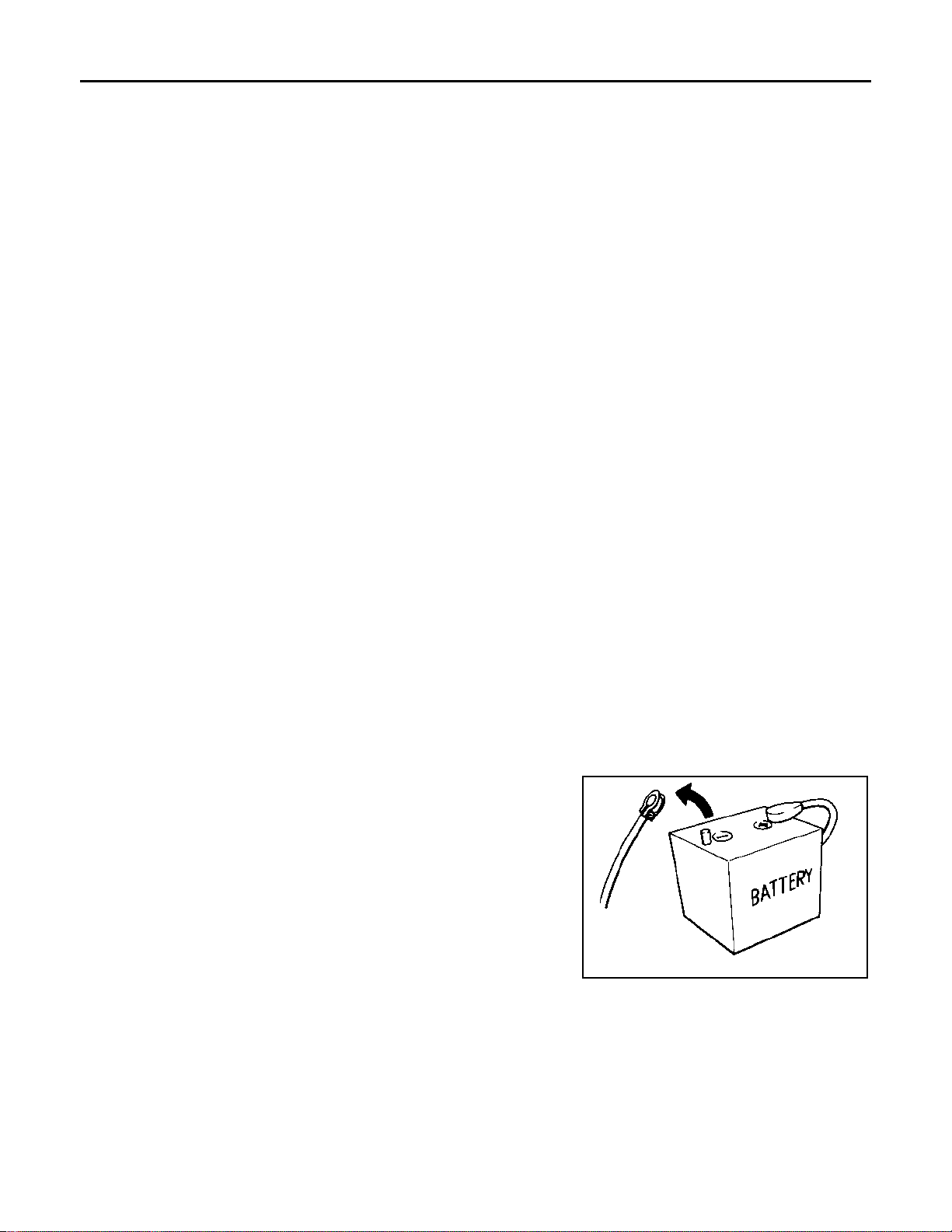
• When disconnecting the 12V battery terminal, turn off the ACC
power before disconnecting the 12V battery terminal, observing
“How to disconnect 12V battery terminal” described below.
NOTE:
Some ECUs operate for a certain fixed time even after ignition
switch is turned OFF and ignition power supply is stopped. If the
battery terminal is disconnected before ECU stops, accidental DTC
detection or ECU data damage may occur.
• For vehicles with the 2-batteries, be sure to connect the main battery and the sub battery before turning ON the ignition switch.
NOTE:
If the ignition switch is turned ON with any one of the terminals of
main battery and sub battery disconnected, then DTC may be detected.
• After installing the 12V battery, always check "Self Diagnosis Result" of all ECUs and erase DTC.
NOTE:
The removal of 12V battery may cause a DTC detection error.
SEF289H
HOW TO DISCONNECT 12V BATTERY TERMINAL
Disconnect 12V battery terminal according to Instruction 1 or Instruction 2 described below.
For vehicles parked by ignition switch OFF, refer to Instruction 2.
INSTRUCTION 1
1. Open the hood.
ACC-2
Page 3

PRECAUTIONS
< PRECAUTION >
2. Turn key switch to the OFF position with the driver side door opened.
3. Get out of the vehicle and close the driver side door.
4. Wait at least 3 minutes. For vehicle with the engine listed below, remove the battery terminal after a lapse
of the specified time.
D4D engine : 20 minutes
HRA2DDT : 12 minutes
K9K engine : 4 minutes
M9R engine : 4 minutes
R9M engine : 4 minutes
V9X engine : 4 minutes
CAUTION:
While waiting, never operate the vehicle such as locking, opening, and closing doors. Violation of
this caution results in the activation of ACC power supply according to the Auto ACC function.
5. Remove 12V battery terminal.
CAUTION:
After installing 12V battery, always check self-diagnosis results of all ECUs and erase DTC.
INSTRUCTION 2 (FOR VEHICLES PARKED BY IGNITION SWITCH OFF)
1. Unlock the door with intelligent key or remote keyless entry.
NOTE:
At this moment, ACC power is supplied.
2. Open the driver side door.
3. Open the hood.
4. Close the driver side door.
5. Wait at least 3 minutes.
CAUTION:
While waiting, never operate the vehicle such as locking, opening, and closing doors. Violation of
this caution results in the activation of ACC power supply according to the Auto ACC function.
6. Remove 12V battery terminal.
CAUTION:
After installing 12V battery, always check self-diagnosis results of all ECUs and erase DTC.
A
ACC
C
D
E
F
G
H
I
J
K
ACC-3
L
M
N
O
P
Page 4
ACCELERATOR CONTROL SYSTEM
< REMOVAL AND INSTALLATION >
REMOVAL AND INSTALLATION
ACCELERATOR CONTROL SYSTEM
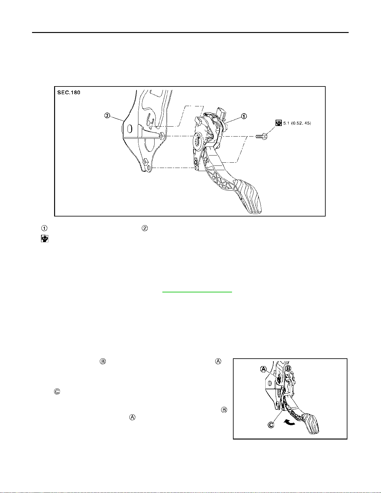
Exploded View INFOID:0000000010782913
JSBIA4306GB
Accelerator pedal assembly Brake pedal assembly
: N·m (kg-m, in-lb)
Removal and Installation INFOID:0000000010782914
REMOVAL
1. Disconnect accelerator pedal position sensor harness connector.
2. Remove brake pedal assembly. Refer to BR-85, "
3. Loosen mounting bolts, and remove accelerator pedal assembly.
CAUTION:
• Never disassemble accelerator lever. Never remove accelerator pedal position sensor from
accelerator lever.
• Avoid impact from dropping etc. during handling.
• Be careful to keep accelerator lever away from water.
INSTALLATION
Note the following, and install in the reverse order of removal.
• Install the protrusion of the bracket into the locating hole of
the accelerator pedal assembly before tightening the accelerator
pedal assembly mounting bolts.
: Locating pin
Exploded View". (RHD models)
CAUTION:
• When inserting accelerator pedal assembly to protrusion ,
never scratch locating hole with the protrusion.
• Tighten bolts with the locating pin securely inserted in the
bracket hole.
CAUTION:
When harness connector of accelerator pedal position sensor is disconnected, perform “ACCELERATOR PEDAL RELEASED POSITION LEARNING”. Refer to following;
JSBIA4307ZZ
ACC-4
Page 5

ACCELERATOR CONTROL SYSTEM
< REMOVAL AND INSTALLATION >
Engine Reference
MR20DD : EC-144, "
QR25DE : EC-553, "Description"
R9M : —
Description"
Inspection INFOID:0000000010782915
INSPECTION AFTER INSTALLATION
• Check accelerator pedal moves smoothly within the whole operation range when it is fully depressed and
released.
• Check accelerator pedal securely returns to the fully released position.
• For the electrical inspection of accelerator pedal position sensor. Refer to following;
Engine Reference
MR20DD : EC-373, "
QR25DE : EC-759, "Component Inspection"
R9M : EC-1181, "Component Inspection (Accelerator Pedal Position Sensor)"
Component Inspection"
A
ACC
C
D
E
F
G
H
K
M
N
O
P
I
J
L
ACC-5
Page 6

DRIVER INFORMATION & MULTIMEDIA
A
B
SECTION AV
AUDIO, VISUAL & NAVIGATION SYSTEM
CONTENTS
BASE AUDIO
PRECAUTION ...............................................
PRECAUTIONS ...................................................6
Precaution for Supplemental Restrain t System
(SRS) "AIR BAG" and "SEAT BELT PRE-TEN-
SIONER" ...................................................................
Precautions for Removing Battery Terminal .............6
Precaution for Trouble Diagnosis ..............................7
Precaution for Harness Repair ..................................7
SYSTEM DESCRIPTION ..............................9
COMPONENT PARTS ........................................9
Component Parts Location . .......................................9
Audio Unit ................................................................12
Speaker ........................... ........................................12
Microphone .............................................................13
Antenna and Antenna Feeder .................................13
USB Connector and AUX Jack ...............................16
Steering Switch .......................................................16
SYSTEM .............................................................17
AUDIO SYSTEM ........................................................17
AUDIO SYSTEM : System Description ...................17
AUDIO SYSTEM : Circuit Diagram .........................19
DIAGNOSIS SYSTEM (AUDIO UNIT) ................20
On Board Diagnosis Function .................................20
ECU DIAGNOSIS INFORMATION ..............21
AUDIO UNIT .......................................................21
Reference Value .....................................................21
WIRING DIAGRAM ......................................24
BASE AUDIO .....................................................24
Wiring Diagram .......................................................24
BASIC INSPECTION ...................................32
DIAGNOSIS AND REPAIR WORK FLOW .......32
Work Flow ................................................................32
6
DTC/CIRCUIT DIAGNOSIS .........................34
POWER SUPPLY AND GROUND CIRCUIT ....34
AUDIO UNIT ............. ... .... ... ... ... ..................................34
6
AUDIO UNIT : Diagnosis Procedure .......................34
AV COMMUNICATION CIRCUIT ......................35
Diagnosis Procedure ...............................................35
VEHICLE SPEED SIGNAL CIRCUIT ................36
Component Function Check ....................................36
Diagnosis Procedure ...............................................36
MICROPHONE SIGNAL CIRCUIT ....................38
Description .......................... ... ....... ...... ....... ...... ........38
Diagnosis Procedure ...............................................38
STEERING SWITCH SIGNAL A CIRCUIT .......40
Diagnosis Procedure ...............................................40
Component Inspection .............................................41
STEERING SWITCH SIGNAL B CIRCUIT .......42
Diagnosis Procedure ...............................................42
Component Inspection .............................................43
STEERING SWITCH SIGNAL GND CIRCUIT ...44
Description .......................... ... ....... ...... ....... ...... ........44
Diagnosis Procedure ...............................................44
Component Inspection .............................................44
SYMPTOM DIAGNOSIS ..............................46
AUDIO SYSTEM SYMPTOMS ..........................46
Symptom Table .......................................................46
HANDS-FREE PHONE SYMPTOMS ................48
Symptom Table .......................................................48
NORMAL OPERATING CONDITION ...............49
C
D
E
F
G
H
I
J
K
L
M
AV
O
P
AV-1
Page 7

Description ....................... .......................... ............. 49
REMOVAL AND INSTALLATION ............... 51
Circuit Diagram .......................................................90
Fail-Safe (NAVI Control Unit) .................................. 91
Fail-Safe (Around View Monitor Control Unit) ......... 92
AUDIO UNIT ......................................................51
Removal and Installation ........................................ 51
FRONT DOOR SPEAKER ................................. 52
Removal and Installation ........................................ 52
REAR DOOR SPEAKER ...................................53
Removal and Installation ........................................ 53
FRONT SQUAWKER .........................................54
Removal and Installation ........................................ 54
USB CONNECTOR AND AUX JACK ............... 55
Removal and Installation ........................................ 55
MICROPHONE ...................................................56
Removal and Installation ........................................ 56
STEERING SWITCH ..........................................57
Removal and Installation ........................................ 57
ROOF ANTENNA .............................................. 58
Exploded View ........ ... ... ... ... .................................... 58
Removal and Installation ........................................ 58
ANTENNA FEEDER ..........................................59
Feeder Layout ........................................................ 59
WITH NAVIGATION
PRECAUTION ............................................. 61
PRECAUTIONS ................................................. 61
Precaution for Supplemental Restraint System
(SRS) "AIR BAG" and "SEAT BELT PRE-TEN-
SIONER" ............................. ................. ...................
Precautions for Removing Battery Terminal ........... 61
Precaution for Trouble Diagnosis ........................... 62
Precaution for Harness Repair ............................... 62
61
SYSTEM DESCRIPTION ............................ 64
COMPONENT PARTS ....................................... 64
Component Parts Location ..................................... 64
NAVI Control Unit ................................................... 68
Speaker .................................................................. 69
Microphone ...................... ....................................... 70
Steering Switch ....................................................... 71
Antenna and Antenna Feeder ................... ... .... ...... 71
USB Connector and AUX Jack .. ... ... .... ... ... ... .... ...... 76
SD Card ..................................................... ... .... ...... 76
Steering Angle Sensor ............................................ 76
Around View Monitor Control Unit .......................... 76
Front Camera ......................................................... 76
Side Camera ........................................................... 77
Rear Camera .......................................................... 77
DIAGNOSIS SYSTEM (NAVI CONTROL
UNIT) ..................................................................
On Board Diagnosis Function ................................. 96
CONSULT Function ................................................97
96
DIAGNOSIS SYSTEM (AROUND VIEW MON-
ITOR CONTROL UNIT) .....................................
CONSULT Function ................................................99
99
ECU DIAGNOSIS INFORMATION ............ 105
NAVI CONTROL UNIT .....................................105
Reference Value ................................................... 105
Fail-Safe (NAVI Control Unit) ................................ 109
DTC Inspection Priority Chart ............................... 109
DTC Index ............................................................. 110
AROUND VIEW MONITOR CONTROL UNIT ..111
Reference Value ................................................... 111
Fail-Safe (Around View Monitor Control Unit) ....... 117
DTC Inspection Priority Chart ............................... 120
DTC Index ............................................................. 120
WIRING DIAGRAM ...................................122
NAVIGATION SYSTEM ....................................122
LHD .................................. ...................... .................. 122
LHD : Wiring Diagram ........................................... 122
RHD ......................................................................... 137
RHD : Wiring Diagram .......................................... 138
BASIC INSPECTION .................................153
DIAGNOSIS AND REPAIR WORKFLOW ........153
MULTI AV SYSTEM .............................. ... .... ... ... ... .. 153
MULTI AV SYSTEM : Work Flow .......................... 153
AROUND VIEW MONITOR SYSTEM ..................... 154
AROUND VIEW MONITOR SYSTEM : Work Flow
.
155
INSPECTION AND ADJUSTMENT ..................157
ADDITIONAL SERVICE WHEN REPLACING NAVI
CONTROL UNIT ......................................................
ADDITIONAL SERVICE WHEN REPLACING
NAVI CONTROL UNIT : Description .....................
CONFIGURATION (NAVI CONTROL UNIT) ........... 157
CONFIGURATION (NAVI CONTROL UNIT) : De-
scription ............................ ................ ................ .....
CONFIGURATION (NAVI CONTROL UNIT) :
Work Procedure ....................................................
157
157
157
157
SYSTEM ............................................................. 78
System Description ................................................. 78
ADDITIONAL SERVICE WHEN REPLACING
AROUND VIEW MONITOR CONTROL UNIT .........
AV-2
158
Page 8

ADDITIONAL SERVICE WHEN REPLACING
AROUND VIEW MONITOR CONTROL UNIT :
Description ............................................................
ADDITIONAL SERVICE WHEN REPLACING
AROUND VIEW MONITOR CONTROL UNIT :
Work Procedure ....................................................
CONFIGURATION (AROUND VIEW MONITOR
CONTROL UNIT) .....................................................
CONFIGURATION (AROUND VIEW MONITOR
CONTROL UNIT) : Work Procedure .....................
PREDICTIVE COURSE LINE CENTER POSITION
ADJUSTMENT .......................... ...............................
PREDICTIVE COURSE LINE CENTER POSI-
TION ADJUSTMENT : Description .......................
PREDICTIVE COURSE LINE CENTER POSI-
TION ADJUSTMENT : Work Procedure ...............
CALIBRATING CAMERA IMAGE (AROUND VIEW
MONITOR) ...............................................................
CALIBRATING CAMERA IMAGE (AROUND
VIEW MONITOR) : Description .............................
CALIBRATING CAMERA IMAGE (AROUND
VIEW MONITOR) : Work Procedure .....................
158
159
159
159
160
160
161
161
161
161
DTC/CIRCUIT DIAGNOSIS .......................166
C1A00 CONTROL UNIT ...................................166
DTC Description ....................................................166
Diagnosis Procedure .......... .... ...............................166
C1A01 POWER SUPPLY CIRCUIT .................167
DTC Description ....................................................167
Diagnosis Procedure .......... .... ...............................167
C1A03 VEHICLE SPEED SENSOR .................168
DTC Description ....................................................168
Diagnosis Procedure .......... .... ...............................168
C1A04 ABS/TCS/VDC SYSTEM ......................170
DTC Description ....................................................170
Diagnosis Procedure .......... .... ...............................170
C1A07 CVT .......................................................171
DTC Description ....................................................171
Diagnosis Procedure .......... .... ...............................171
C1A39 STEERING ANGLE SENSOR ..............172
DTC Description ....................................................172
Diagnosis Procedure .......... .... ...............................172
C1B56 SONAR .................................................173
DTC Description ....................................................173
Diagnosis Procedure .......... .... ...............................173
U0122 ABS ACTUATOR AND ELECTRIC
UNIT (CONTROL UNIT) ...................................
DTC Description ....................................................174
Diagnosis Procedure .......... .... ...............................174
174
U0416 ABS ACTUATOR AND ELECTRIC
UNIT (CONTROL UNIT) ..................................
DTC Description ....................................................175
Diagnosis Procedure .............................................175
175
U0428 STEERING ANGLE SENSOR .............176
DTC Description ....................................................176
Diagnosis Procedure .............................................176
U1000 CAN COMM CIRCUIT ......................... 177
NAVI CONTROL UNIT .............................................177
NAVI CONTROL UNIT : DTC Description .............177
NAVI CONTROL UNIT : Diagnosis Procedure ......177
AROUND VIEW MONITOR CONTROL UNIT .........177
AROUND VIEW MONITOR CONTROL UNIT :
DTC Description ....................................................
AROUND VIEW MONITOR CONTROL UNIT :
Diagnosis Procedure ............................................
178
178
U1010 CONTROL UNIT (CAN) .......................180
NAVI CONTROL UNIT .............................................180
NAVI CONTROL UNIT : DTC Description .............180
NAVI CONTROL UNIT : Diagnosis Procedure .....180
AROUND VIEW MONITOR CONTROL UNIT .........180
AROUND VIEW MONITOR CONTROL UNIT :
DTC Description ....................................................
AROUND VIEW MONITOR CONTROL UNIT : Di-
agnosis Procedure .................................................
180
181
U111A REAR CAMERA IMAGE SIGNAL CIR-
CUIT ................................................................
DTC Description ....................................................182
Diagnosis Procedure .............................................182
182
U111B SIDE CAMERA RH IMAGE SIGNAL
CIRCUIT ..........................................................
DTC Description ....................................................186
Diagnosis Procedure .............................................186
186
U111C FRONT CAMERA IMAGE SIGNAL
CIRCUIT ..........................................................
DTC Description ....................................................192
Diagnosis Procedure .............................................192
192
U111D SIDE CAMERA LH IMAGE SIGNAL
CIRCUIT ..........................................................
DTC Description ....................................................195
Diagnosis Procedure .............................................195
195
U112F EPS CIRCUIT ...................................... 201
DTC Description ....................................................201
Diagnosis Procedure .............................................201
U1217 NAVI CONTROL UNIT ........................ 202
DTC Description ....................................................202
Diagnosis Procedure ............................................202
A
B
C
D
E
F
G
H
I
J
K
L
M
AV
O
P
U1229 NAVI CONTROL UNIT ........................ 203
AV-3
Page 9

DTC Description ....................................................203
Diagnosis Procedure ............................................ 203
U122F NAVI CONTROL UNIT ......................... 204
DTC Description ....................................................204
Diagnosis Procedure .............................................204
U1232 STEERING ANGLE SENSOR .............. 205
DTC Description ....................................................205
Diagnosis Procedure .............................................205
U1244 GPS ANTENNA .................................... 206
DTC Description ....................................................206
Diagnosis Procedure .............................................206
U1263 USB ...................................................... 208
DTC Description ....................................................208
Diagnosis Procedure .............................................208
U12AA CONFIGURATION ERROR ................ 209
DTC Description ....................................................209
Diagnosis Procedure ............................................ 209
U12AB ANTENNA ........................................... 210
DTC Description ....................................................210
Diagnosis Procedure .............................................210
U12AC NAVI CONTROL UNIT ........................ 212
DTC Description ....................................................212
Diagnosis Procedure ............................................ 212
U12AD NAVI CONTROL UNIT ........................ 213
DTC Description ....................................................213
Diagnosis Procedure ............................................ 213
U12AE NAVI CONTROL UNIT ........................ 214
DTC Description ....................................................214
Diagnosis Procedure ............................................ 214
U12AF NAVI CONTROL UNIT ........................ 215
DTC Description ....................................................215
Diagnosis Procedure ............................................ 215
U12B0 POWER SUPPLY VOLTAGE .............. 216
DTC Description ....................................................216
Diagnosis Procedure ............................................ 216
U12B1 POWER SUPPLY VOLTAGE .............. 217
DTC Description ....................................................217
Diagnosis Procedure ............................................ 217
U12B2 DAB ANTENNA ................................... 218
DTC Description ....................................................218
Diagnosis Procedure .............................................218
U1300 AV COMM CIRCUIT ............................. 220
DTC Description ....................................................220
Diagnosis Procedure .............................................220
U1302 CAMERA POWER VOLT ..................... 222
DTC Description ....................................................222
Diagnosis Procedure .............................................222
U1304 CAMERA IMAGE CALIBRATION ........230
DTC Description ............ ... ... ... ............................... 230
Diagnosis Procedure ..... ... ..................................... 230
U1305 CONFIG UNFINISH ...............................231
DTC Description ............ ... ... ... ............................... 231
Diagnosis Procedure ..... ... ..................................... 231
U1308 REAR CAMERA ....................................232
DTC Description ............ ... ... ... ............................... 232
Diagnosis Procedure ..... ... ..................................... 232
U1309 AIR PUMP .............................................233
DTC Description ............ ... ... ... ............................... 233
Diagnosis Procedure ..... ... ..................................... 233
U130A PUMP CONTROL UNIT .......................234
DTC Description ............ ... ... ... ............................... 234
Diagnosis Procedure ..... ... ..................................... 234
U130B REAR CAMERA ...................................235
DTC Description ............ ... ... ... ............................... 235
Diagnosis Procedure ..... ... ..................................... 235
U1310 NAVI CONTROL UNIT ..........................236
DTC Description ............ ... ... ... ............................... 236
Diagnosis Procedure ..... ... ..................................... 236
U1320 REPROGRAMMING .............................237
DTC Description ............ ... ... ... ............................... 237
Diagnosis Procedure ..... ... ..................................... 237
U150E BCM CIRCUIT ......................................238
DTC Description ............ ... ... ... ............................... 238
Diagnosis Procedure ..... ... ..................................... 238
U1971 SONAR ..................................................239
DTC Description ............ ... ... ... ............................... 239
Diagnosis Procedure ..... ... ..................................... 239
U1972 EPS .......................................................240
DTC Description ............ ... ... ... ............................... 240
Diagnosis Procedure ..... ... ..................................... 240
POWER SUPPLY AND GROUND CIRCUIT ....241
NAVI CONTROL UNIT ............................. .... ... ... ... .. 241
NAVI CONTROL UNIT : Diagnosis Procedure ..... 241
AROUND VIEW MONITOR CONTROL UNIT ......... 241
AROUND VIEW MONITOR CONTROL UNIT : Di-
agnosis Procedure ................................................
241
MICROPHONE SIGNAL CIRCUIT ...................243
Description ............................................................ 243
Diagnosis Procedure ..... ... ..................................... 243
CAMERA IMAGE SIGNAL CIRCUIT ...............245
Description ............................................................ 245
Diagnosis Procedure ..... ... ..................................... 245
STEERING SWITCH SIGNAL A CIRCUIT .......247
Diagnosis Procedure ..... ... ..................................... 247
AV-4
Page 10

Component Inspection .................... ......................
248
STEERING SWITCH SIGNAL B CIRCUIT .......249
Diagnosis Procedure .......... .... ...............................249
Component Inspection .................... ......................250
STEERING SWITCH GROUND CIRCUIT ........251
Diagnosis Procedure .......... .... ...............................251
Component Inspection .................... ......................251
USB CONNECTOR AND AUX JACK .............266
Removal and Installation .......................................266
GPS ANTENNA ............................................... 267
Feeder Layout ................. ... ...................................267
Removal and Installation .......................................267
AROUND VIEW MONITOR CONTROL UNIT . 268
Removal and Installation .......................................268
A
B
C
SYMPTOM DIAGNOSIS ............................ 252
MULTI AV SYSTEM .........................................252
Symptom Table .....................................................252
HANDS-FREE PHONE SYMPTOMS ...............256
Symptom Table .....................................................256
NORMAL OPERATING CONDITION ...............257
Description ............................................................257
REMOVAL AND INSTALLATION .............262
NAVI CONTROL UNIT .....................................262
Removal and Installation ........ ... ... .........................262
FRONT DOOR SPEAKER ...............................263
Removal and Installation ........ ... ... .........................263
REAR DOOR SPEAKER ..................................264
Removal and Installation ........ ... ... .........................264
FRONT SQUAWKER .......................................265
Removal and Installation ........ ... ... .........................265
FRONT CAMERA ............................................269
Removal and Installation .......................................269
REAR CAMERA ..............................................270
Removal and Installation .......................................270
SIDE CAMERA ................................................271
Removal and Installation .......................................271
MICROPHONE ................................................ 272
Removal and Installation .......................................272
STEERING SWITCH .......................................273
Removal and Installation .......................................273
STEERING ANGLE SENSOR .........................274
Exploded View .......................................................274
Removal and Installation .......................................274
ROOF ANTENNA ............................................275
Exploded View .......................................................275
Removal and Installation .......................................275
ANTENNA FEEDER ........................................276
Feeder Layout ................. ... ...................................276
D
E
F
G
H
I
J
AV
K
L
M
O
P
AV-5
Page 11
PRECAUTIONS
< PRECAUTION >
[BASE AUDIO]
PRECAUTION
PRECAUTIONS
Precaution for Supplemental Restraint System (SRS) "AIR BAG" and "SEAT BELT
PRE-TENSIONER"
The Supplemental Restraint System such as “AIR BAG” and “SEAT BELT PRE-TENSIONER”, used along
with a front seat belt, helps to reduce the risk or severity of injury to the driver and front passenger for certain
types of collision. Information necessary to service the system safely is included in the “SRS AIR BAG” and
“SEAT BELT” of this Service Manual.
WARNING:
Always observe the following items for preventing accidental activation.
• To avoid rendering the SRS inoperative, which could increase the risk of personal injury or death in
the event of a collision that would result in air bag inflation, all maintenance must be performed by
an authorized NISSAN/INFINITI dealer.
• Improper maintenance, including incorrect removal and installation of the SRS, can lead to personal
injury caused by unintentional activation of the system. For removal of Spiral Cable and Air Bag
Module, see “SRS AIR BAG”.
• Never use electrical test equipment on any circuit related to the SRS unless instructed to in this Service Manual. SRS wiring harnesses can be identified by yellow and/or orange harnesses or harness
connectors.
INFOID:0000000010714743
PRECAUTIONS WHEN USING POWER TOOLS (AIR OR ELECTRIC) AND HAMMERS
WARNING:
Always observe the following items for preventing accidental activation.
• When working near the Air Bag Diagnosis Sensor Unit or other Air Bag System sensors with the
ignition ON or engine running, never use air or electric power tools or strike near the sensor(s) with
a hammer. Heavy vibration could activate the sensor(s) and deploy the air bag(s), possibly causing
serious injury.
• When using air or electric power tools or hammers, always switch the ignition OFF, disconnect the
battery, and wait at least 3 minutes before performing any service.
Precautions for Removing Battery Terminal INFOID:0000000011010175
• With the adoption of Auto ACC function, ACC power is automatically supplied by operating the intelligent key
or remote keyless entry or by opening/closing the driver side door. In addition, ACC power is supplied even
after the ignition switch is turned to the OFF position, i.e. ACC power is supplied for a certain fixed time.
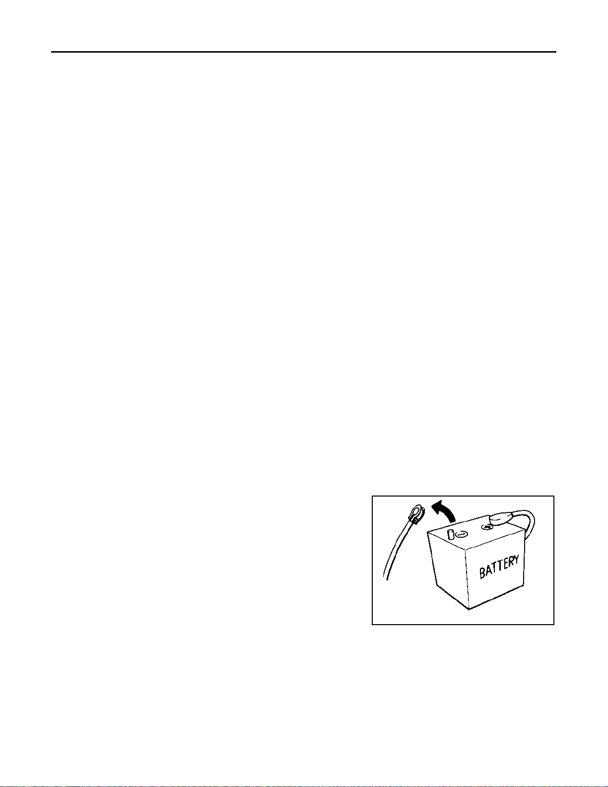
• When disconnecting the 12V battery terminal, turn off the ACC
power before disconnecting the 12V battery terminal, observing
“How to disconnect 12V battery terminal” described below.
NOTE:
Some ECUs operate for a certain fixed time even after ignition
switch is turned OFF and ignition power supply is stopped. If the
battery terminal is disconnected before ECU stops, accidental DTC
detection or ECU data damage may occur.
• For vehicles with the 2-batteries, be sure to connect the main battery and the sub battery before turning ON the ignition switch.
NOTE:
If the ignition switch is turned ON with any one of the terminals of
main battery and sub battery disconnected, then DTC may be detected.
• After installing the 12V battery, always check "Self Diagnosis Result" of all ECUs and erase DTC.
NOTE:
The removal of 12V battery may cause a DTC detection error.
SEF289H
HOW TO DISCONNECT 12V BATTERY TERMINAL
Disconnect 12V battery terminal according to Instruction 1 or Instruction 2 described below.
For vehicles parked by ignition switch OFF, refer to Instruction 2.
INSTRUCTION 1
1. Open the hood.
AV-6
Page 12
PRECAUTIONS
< PRECAUTION >
2. Turn key switch to the OFF position with the driver side door opened.
3. Get out of the vehicle and close the driver side door.
4. Wait at least 3 minutes. For vehicle with the engine listed below, remove the battery terminal after a lapse
of the specified time.
D4D engine : 20 minutes
HRA2DDT : 12 minutes
K9K engine : 4 minutes
M9R engine : 4 minutes
R9M engine : 4 minutes
V9X engine : 4 minutes
CAUTION:
While waiting, never operate the vehicle such as locking, opening, and closing doors. Violation of
this caution results in the activation of ACC power supply according to the Auto ACC function.
5. Remove 12V battery terminal.
CAUTION:
After installing 12V battery, always check self-diagnosis results of all ECUs and erase DTC.
INSTRUCTION 2 (FOR VEHICLES PARKED BY IGNITION SWITCH OFF)
1. Unlock the door with intelligent key or remote keyless entry.
NOTE:
At this moment, ACC power is supplied.
2. Open the driver side door.
3. Open the hood.
4. Close the driver side door.
5. Wait at least 3 minutes.
CAUTION:
While waiting, never operate the vehicle such as locking, opening, and closing doors. Violation of
this caution results in the activation of ACC power supply according to the Auto ACC function.
6. Remove 12V battery terminal.
CAUTION:
After installing 12V battery, always check self-diagnosis results of all ECUs and erase DTC.
[BASE AUDIO]
Precaution for Trouble Diagnosis INFOID:0000000010714745
A
B
C
D
E
F
G
H
I
J
K
AV COMMUNICATION SYSTEM
• Do not apply voltage of 7.0 V or higher to the measurement terminals.
• Use the tester with its open terminal voltage being 7.0 V or less.
• Be sure to turn ignition switch OFF and disconnect the battery cable from the negative terminal before
checking the circuit.
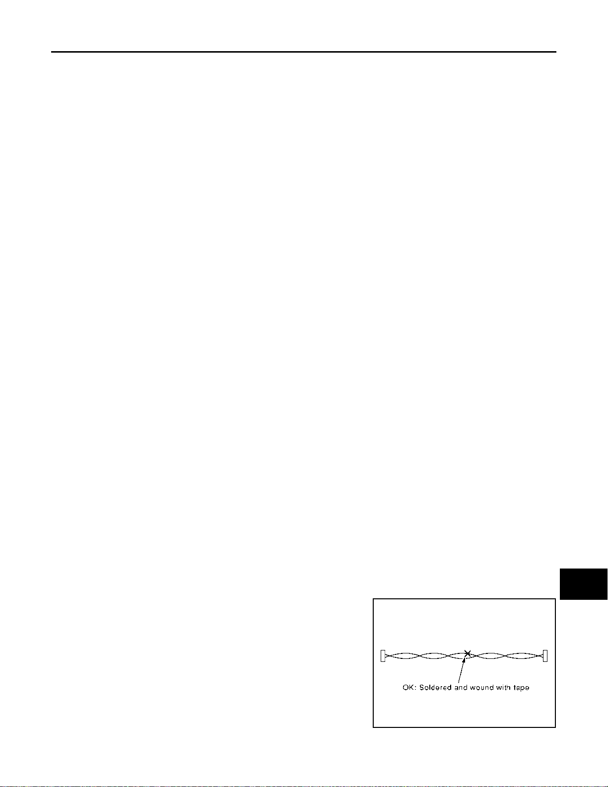
Precaution for Harness Repair INFOID:0000000010714746
AV COMMUNICATION SYSTEM
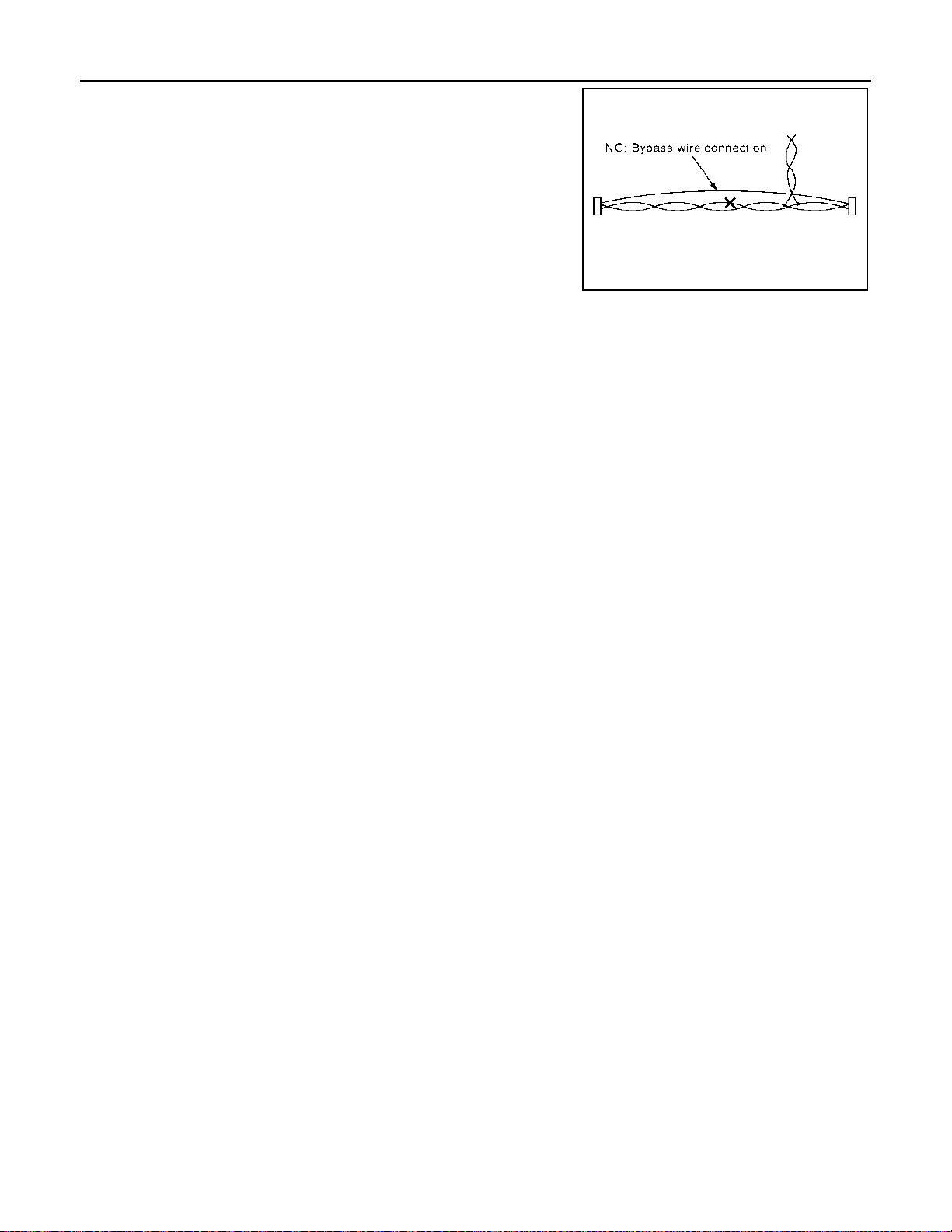
• Solder the repaired parts, and wrap with t ape. [Frays of twisted line
must be within 110 mm (4.33 in).]
PKIA0306E
AV-7
L
M
AV
O
P
Page 13
PRECAUTIONS
< PRECAUTION >
• Do not perform bypass wire connections for the repair parts. (The
spliced wire will become separated and the characteristics of
twisted line will be lost.)
[BASE AUDIO]
PKIA0307E
AV-8
Page 14
< SYSTEM DESCRIPTION >
COMPONENT PARTS
[BASE AUDIO]
SYSTEM DESCRIPTION
COMPONENT PARTS
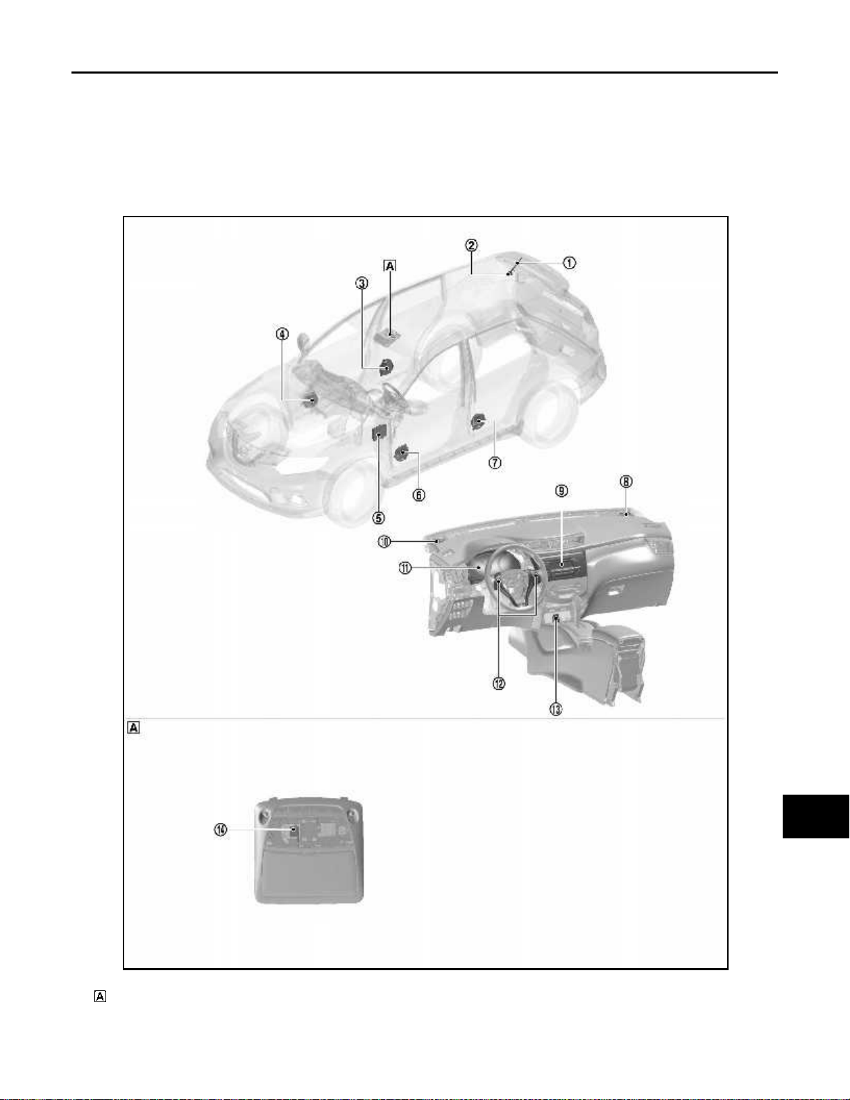
Component Parts Location INFOID:0000000010714747
LHD MODELS
A
B
C
D
E
F
G
H
AV
I
J
K
L
M
O
P
Map lamp
JSNIA7345ZZ
AV-9
Page 15
COMPONENT PARTS
< SYSTEM DESCRIPTION >
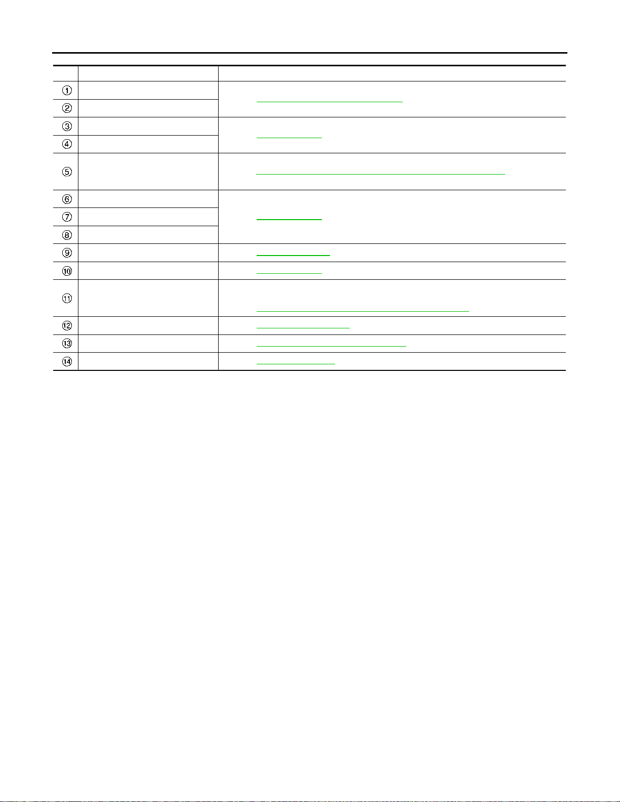
No. Component Function
Antenna rod
Antenna base
Refer to AV-13, "
Antenna and Antenna Feeder".
[BASE AUDIO]
Rear door speaker RH
Front door speaker RH
BCM
Front door speaker LH
Front squawker RH
Audio unit Refer to AV-12, "
Front squawker LH Refer to AV-12, "Speaker".
Combination meter
Steering switch Refer to AV-16, "
USB connector and AUX jack Refer to AV-16, "
Microphone Refer to AV-13, "
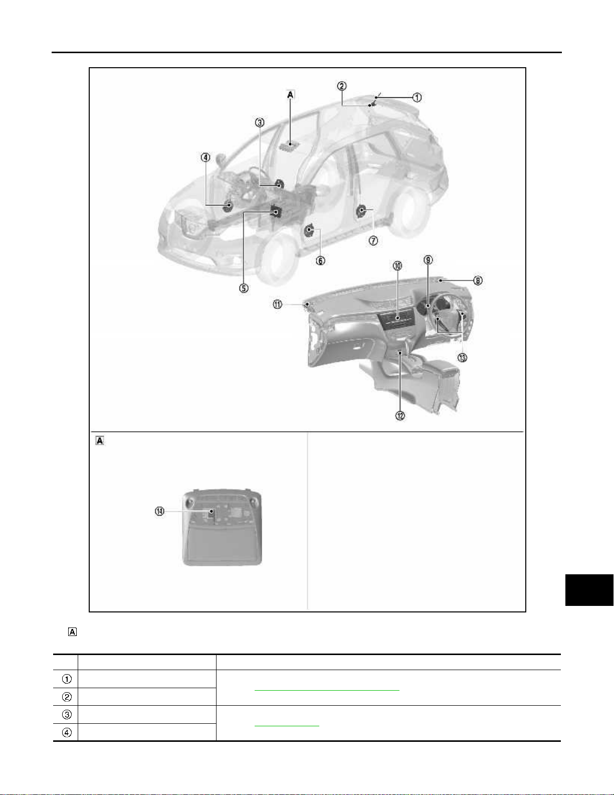
RHD MODELS
Refer to AV-12, "
Transmits the auto ACC input signal to the a udio unit.
Refer to BCS-6, "
stallation.
Refer to AV-12, "
• Transmits the vehicle speed signal to the audio unit.
• Transmits the steering switch signal to the audio unit via AV communication.
Refer to MWI-7, "
Speaker".
BODY CONTROL SYSTEM : Component Parts Location", for detailed in-
Speaker".Rear door speaker LH
Audio Unit".
METER SYSTEM : Component Parts Location", for detailed installation.
Steering Switch".
USB Connector and AUX Jack".
Microphone".
AV-10
Page 16
< SYSTEM DESCRIPTION >
COMPONENT PARTS
[BASE AUDIO]
A
B
C
D
E
F
G
Map lamp
H
I
J
K
L
M
AV
JSNIA7346ZZ
O
No. Component Function
Antenna rod
Antenna base
Rear door speaker RH
Front door speaker RH
Refer to AV-13, "
Refer to AV-12, "
Antenna and Antenna Feeder".
Speaker".
AV-11
P
Page 17
COMPONENT PARTS
< SYSTEM DESCRIPTION >
No. Component Function
Transmits the auto ACC input signal to the a udio unit.
BCM
Front door speaker LH
Refer to BCS-6, "BODY CONTROL SYSTEM : Component Parts Location", for detailed installation.
[BASE AUDIO]
Refer to AV-12, "
Front squawker RH
• Transmits the vehicle speed signal to the audio unit.
Combination meter
Audio unit Refer to AV-12, "
Front squawker LH Refer to AV-12, "
USB connector and AUX jack Refer to AV-16, "
Steering switch Refer to AV-16, "
Microphone Refer to AV-13, "
• Transmits the steering switch signal to the audio unit via AV communication.
Refer to MWI-7, "
Speaker".Rear door speaker LH
METER SYSTEM : Component Parts Location", for detailed installation.
Audio Unit".
Speaker".
USB Connector and AUX Jack".
Steering Switch".
Microphone".
Audio Unit
Description
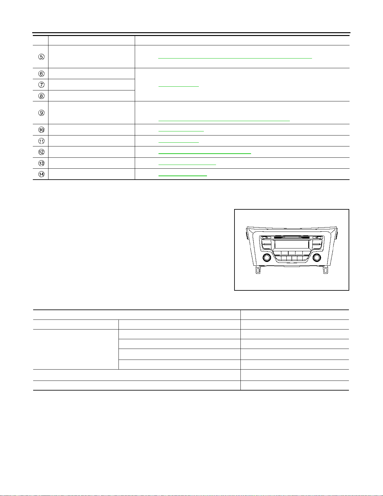
• AM/FM electronic tuner radio and CD player are integrated into the
audio unit.
• The audio unit supports CD-R/CD-RW and provides the playback
of MP3/WMA music files.
INFOID:0000000010714748
JSNIA7347ZZ
Specification
Audio amplifier 16 W × 4
AM/FM electric tuner FM diversity function Without
CD changer Without
CD drive
®
Bluetooth
Steering switch With
module
Used disc φ 12 cm (4.7 in)
CD-R/CD-RW playback function
MP3 / WMA playback function With
With
With
*
*: If the reflectance of the surface of the media is low, the data may not be read.
Speaker INFOID:0000000010714749
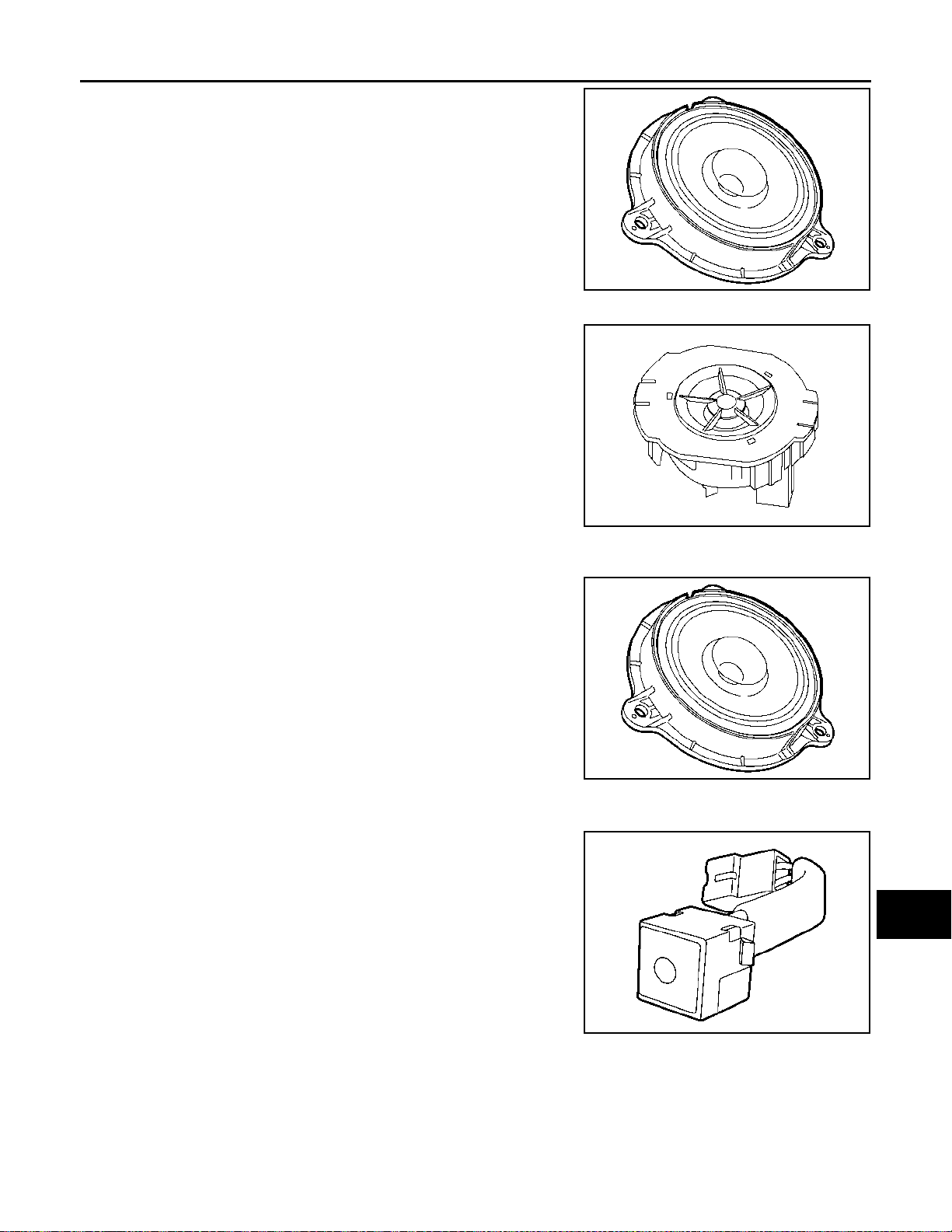
FRONT DOOR SPEAKER
• φ 16 cm speaker is installed to the bottom of the front door.
AV-12
Page 18
COMPONENT PARTS
< SYSTEM DESCRIPTION >
• Sound signal is input from the audio unit to output high, mid, and
low range sounds.
Rated input : 20 W
Maximum
input
Impedance : 4 Ω
FRONT SQUAWKER
• φ8.0 cm squawker for high-range sounds is installed in the instrument panel assembly.
• Sound signal is input from the audio unit to output high range
sounds.
: 40 W
[BASE AUDIO]
A
B
C
JSNIA5958ZZ
D
E
F
G
ALNIA1593ZZ
REAR DOOR SPEAKER
• φ 16 cm speaker is installed to the bottom of the rear door.
• Sound signal is input from the audio unit to output high, mid, and
low range sounds.
Rated input : 20 W
Maximum
input
: 40 W
Impedance : 4 Ω
JSNIA5958ZZ
Microphone INFOID:0000000010957681
• The microphone is installed on the map lamp assembly.
• The power is supplied from the audio unit to the microphone, transmitting sound signals to the audio unit at the during hands-free
phone communication.
H
I
J
K
L
M
AV
JPNIA1448ZZ
Antenna and Antenna Feeder INFOID:0000000010714750
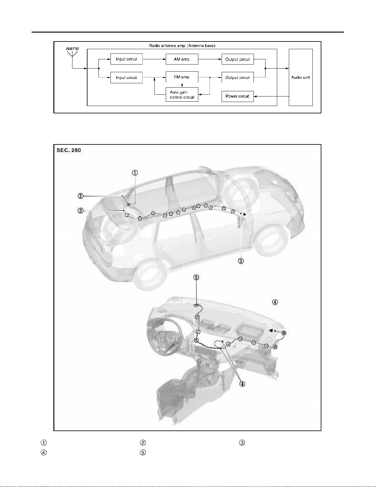
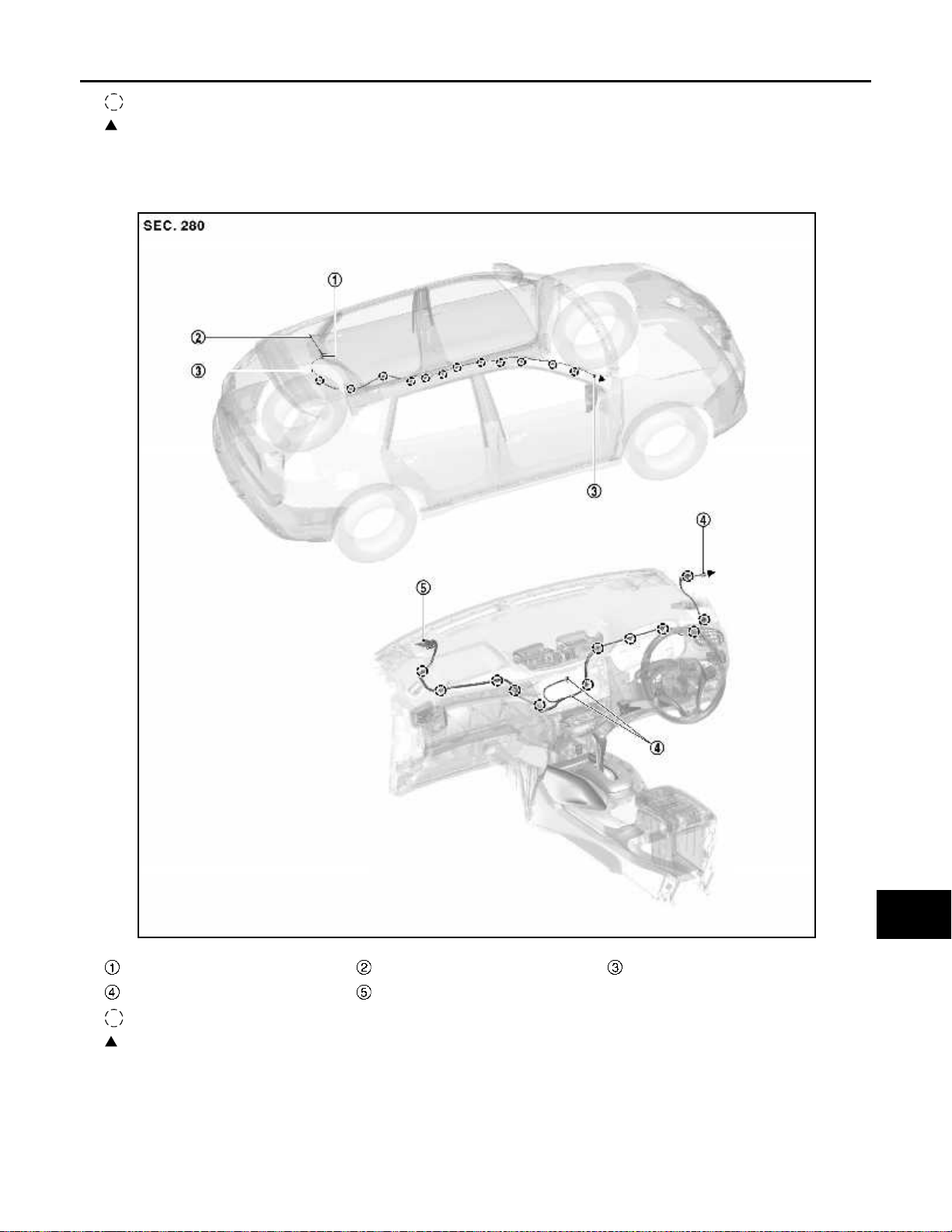
ANTENNA AMP. AND RADIO ANTENNA
• AM/FM radio rod antenna and antenna base are located on the rear of the roof.
• The antenna amp. is built into the antenna base.
AV-13
O
P
Page 19
COMPONENT PARTS
< SYSTEM DESCRIPTION >
• The AM/FM radio main antenna path has an antenna amp. to obtain sufficient reception power.
ANTENNA FEEDER LAYOUT
LHD Models
[BASE AUDIO]
JSNIA7229GB
Antenna base Antenna rod With clip connector
Connector
GPS antenna
*
AV-14
JSNIA7348ZZ
Page 20
< SYSTEM DESCRIPTION >
COMPONENT PARTS
[BASE AUDIO]
: Clips
: Indicates that the part is connected at points with same symbol in actual vehicle.
*: Not applicable
RHD Models
A
B
C
D
E
F
G
H
Antenna base Antenna rod With clip connector
Connector
: Clips
: Indicates that the part is connected at points with same symbol in actual vehicle.
GPS antenna
*
I
J
K
L
M
AV
JSNIA7349ZZ
O
P
*: Not applicable
AV-15
Page 21
< SYSTEM DESCRIPTION >
COMPONENT PARTS
[BASE AUDIO]
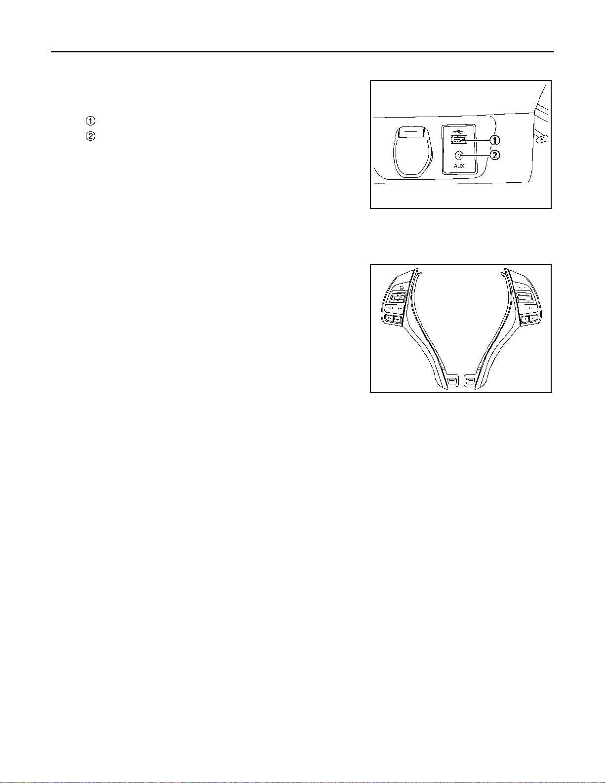
USB Connector and AUX Jack
INFOID:0000000010714751
• USB connector and AUX jack is installed on the instrument lower
panel center.
USB connector
AUX jack
• iPod and USB memory can be connected to the audio unit.
• Connection to an external audio device can provide sound output.
External input terminal for connection φ3.5 mm stereo mini-jack
NOTE:
JSNIA6736ZZ
When connected to monaural mini-jack plug cable, sound may not
be output.
St eering Switch INFOID:0000000010714752
• Hands-free phone and audio operations can be performed.
• This switch is connected to combination meter, and switch operation signal is transmitted to combination meter.
• Combination meter transmits steering switch signal to audio unit
via AV communication.
JSNIA7234ZZ
AV-16
Page 22
< SYSTEM DESCRIPTION >
SYSTEM
[BASE AUDIO]
SYSTEM
AUDIO SYSTEM
AUDIO SYSTEM : System Description INFOID:0000000010714753
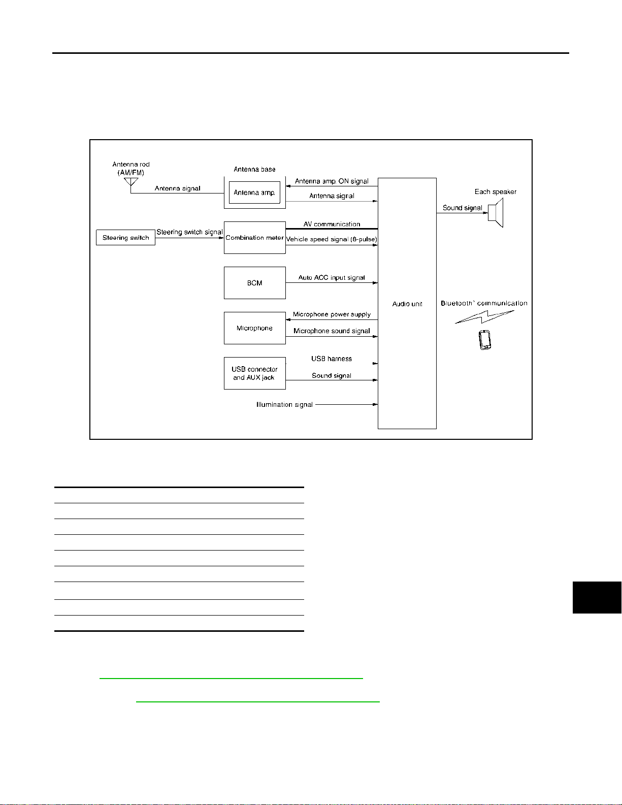
SYSTEM DIAGRAM
A
B
C
D
E
F
G
H
JSNIA7351GB
AUDIO SYSTEM
The audio system is equipped with following functions.
Functions
AM/FM radio
CD playback
AUX connection
USB connection
Speed sensitive volume
®
Bluetooth
Hands-free phone function
Meter display
NOTE:
• The auto ACC function allows the operation of audio without operating the ignition switch. In addition, even
after the ignition switch is turned OFF, audio can be operated for 10 minutes. For the auto ACC function,
refer to PCS-68, "
• The settings of the auto ACC function can be changed with the CONSULT (work support of BCM). For
details, refer to BCS-47, "
audio
AUTO ACC FUNCTION : System Description".
BCM : CONSULT Function (BCM - BCM)".
I
J
K
L
M
AV
O
P
FUNCTION DESCRIPTION
The MP3/WMA playback function enables music to play for a long time: the user need not change the CD during a long trip. The text display function is also adopted so that the title name and artist name of the ID3 tag/
WMA tag can be displayed.
Operating signal
AV-17
Page 23

SYSTEM
< SYSTEM DESCRIPTION >
Audio system operation can be performed with audio fascia switch and steering switch.
AM/FM Radio Function
• AM/FM radio tuner is built into audio unit.
• The radio signal received by the window antenna is input to the antenna amp. and sent to the audio unit.
• Audio unit outputs the sound signal to each speaker.
CD Playback Function
• CD function is built into audio unit.
• Audio unit outputs sound signal to each speaker when CD is inserted to audio unit.
AUX Connection Function
• When the external device is connected to the AUX (auxiliary) input jack, the external device inputs a sound
signal to the audio unit.
• When AUX mode is selected, audio unit outputs sound signal to each speaker.
USB Connection Function
• Music files in USB memory can be played.
• Sound signals are transmitted from USB connector to the audio unit and each speaker.
Speed Sensitive Volume Function
• The audio unit receives the vehicle speed signal from the combination meter and changes the sound volume
in conjunction with the vehicle speed.
• The control level can be selected by the customer.
[BASE AUDIO]
Bluetooth® Audio Mode
• Bluetooth® audio function is built into audio unit.
• Bluetooth
®
audio can play music data in the portable audio by means of Bluetooth® communications
between the portable audio and the audio unit.
• When Bluetooth
Hands-Free Phone function
®
audio mode is selected, audio unit outputs sound signal to each speaker.
• Hands-free communication can be operated by connecting to cellular phone using Bluetooth®.
• Operation is performed by steering switch.
Meter Display
Audio Indicator
• The steering switch is connected to the combination meter.
• The combination meter transmits a steering switch signal to the audio unit via AV communication when the
user operates the audio with the steering switch.
• The audio unit changes the status of function according to the steering switch operation when receiving a
steering switch signal.
• The audio unit transmits an audio indicator signal to the combination meter via AV communication and displays the status of audio on the combination meter (in the information display) when the function is changed
by an operation (including the operation of audio unit switch).
Hands-free Phone Indicator
• When a cell phone that is connected with the audio unit via Bluetooth® communication receives a phone
call, the incoming call is displayed on the information display in combination meter.
®
• When audio unit recognizes an incoming call from a cell phone via Bluetooth
communication, it transmits
the meter display signal to combination meter via AV communication.
• When combination meter receives the meter display signal, it displays the incoming call of cell phone on
information display.
• When an incoming call is received, the driver can operate the steering switch to answer the phone.
• When steering switch is operated, the combination meter receives the steering switch signal, and then combination meter transmits the steering switch signal to the audio unit via AV communication.
• When audio unit receives the steering switch signal, it activates the hands-free phone.
AV-18
Page 24
SYSTEM
< SYSTEM DESCRIPTION >
[BASE AUDIO]
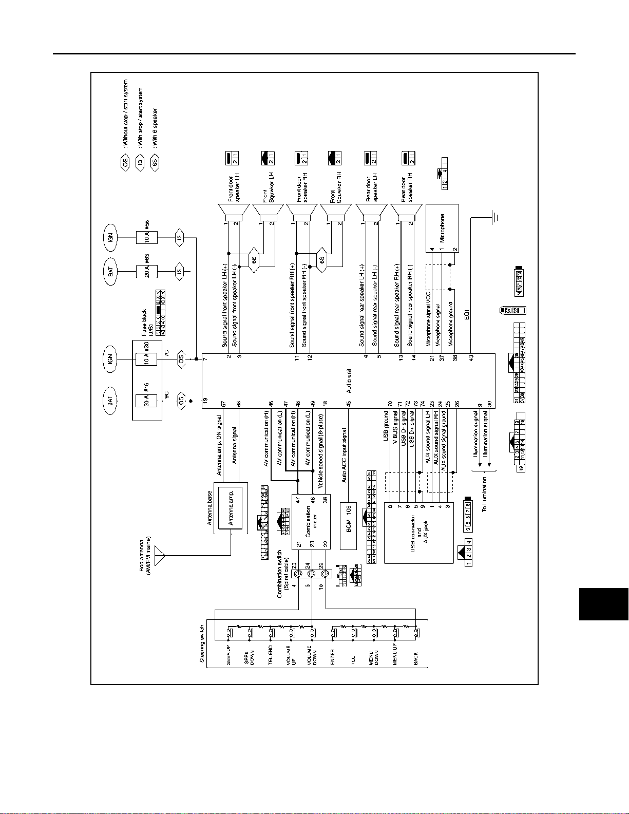
AUDIO SYSTEM : Circuit Diagram INFOID:0000000010714754
A
B
C
D
E
F
G
AV
H
I
J
K
L
M
O
AV-19
JSNIA7352GB
P
Page 25
DIAGNOSIS SYSTEM (AUDIO UNIT)
< SYSTEM DESCRIPTION >
[BASE AUDIO]
DIAGNOSIS SYSTEM (AUDIO UNIT)
On Board Diagnosis Function INFOID:0000000010714755
DESCRIPTION
• On board diagnosis is performed in service mode.
• On board diagnosis checks if the system operates normally.
ON BOARD DIAGNOSIS ITEM
Self-diagnosis mode can perform the following items.
Item Content
ON/OFF setting of the following items can be performed.
• AF (alternate frequency)
AF-Reg
Unit configuration The current system status is displayed.
Monitor
Diagnostics
Region Reception frequency band (the reception area) setting of the radio can be set.
Radio Monitor The reception state of the radio signal can be checked.
LCD Contrast The contrast setting of the display can be adjusted.
Faults Audio system malfunction detected by audio unit can be checked.
Self test Operation check of an audio function can be performed.
Clear fault Faults result can be cleared.
• REG (region)
NOTE:
This item is displayed, but not used.
Comparison can be performed between actual vehicle signal and signal recognized by the audio system.
METHOD OF STARTING
1. Turn ignition switch ON.
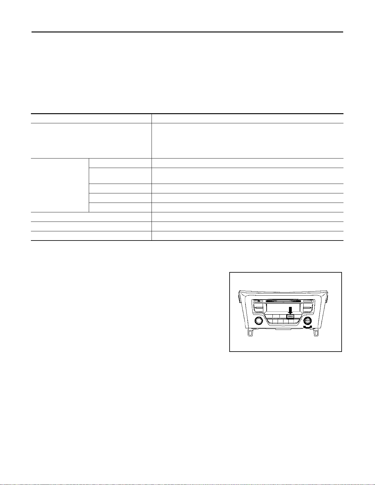
2. Turn the audio unit ON at AM/FM mode.
3. Pressing the “SETUP” switch more than 2 seconds, and then
turn the MENU dial counterclockwise, clockwise and counterclockwise more than 3 clicks respectively while pressing the
“SETUP” switch.
4. When the self-diagnosis mode starts, the initial screen is dis-
played and then, release the “SETUP” switch.
Finishing Self-diagnosis Mode
Turn ignition switch OFF.
JSNIA7353ZZ
AV-20
Page 26
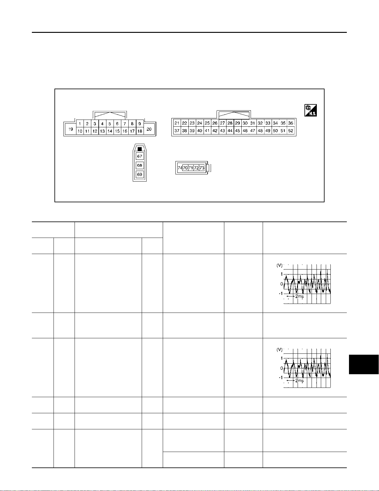
< ECU DIAGNOSIS INFORMATION >
AUDIO UNIT
[BASE AUDIO]
ECU DIAGNOSIS INFORMATION
AUDIO UNIT
Reference Value INFOID:0000000010714756
TERMINAL LAYOUT
JSNIA7230ZZ
PHYSICAL VALUES
Terminal
(Wire color)
+ – Signal name
Description
Input/
Output
Condition Standard
Reference value
(Approx.)
A
B
C
D
E
F
G
H
I
2
(Y)
(W)
3
(R)
(P)
4
(GR)5(BR)
5
(BR)
7
(LG)
9
(V)
3
*1
(R)
*2
(P)
*1
—
*2
—
Groun
d
Groun
d
Outputs
Sound signal front speaker
*1
LH+
*2
Sound signal front speaker
LH−
Sound signal rear speaker
LH+
Sound signal rear speaker
LH−
Ignition signal Input [Ignition switch ON] 9.0 - 16.0 V Battery voltage
Illumination signal Input
Output
Output
[Ignition switch ON]
Sound output
—— — —
[Ignition switch ON]
Sound output
—— — —
[Ignition switch ON]
Lighting switch is 1st or
2nd
[Ignition switch ON]
Lighting switch is OFF
waveform
synchronized
with sound.
Outputs
waveform
synchronized
with sound.
9.0 - 16.0 V 12.0 V
3.2 V or less 0 V
SKIB3609E
SKIB3609E
J
K
L
M
AV
O
P
AV-21
Page 27
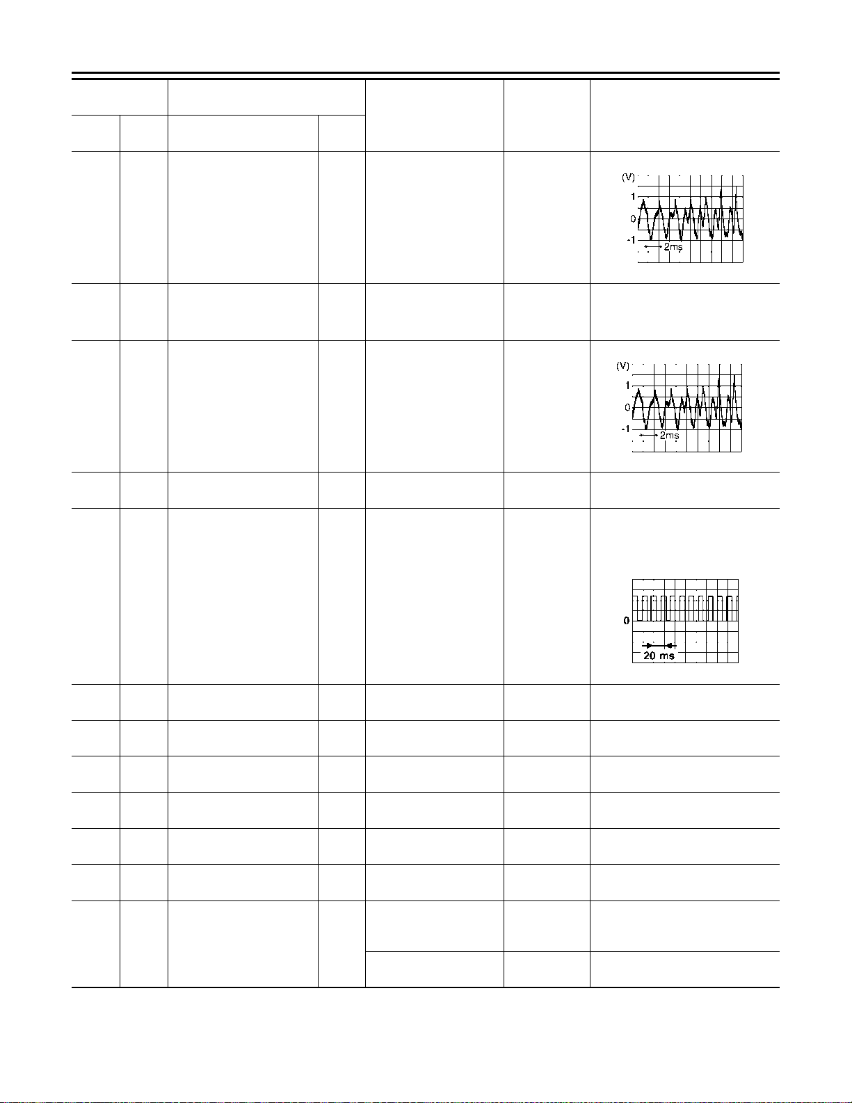
< ECU DIAGNOSIS INFORMATION >
AUDIO UNIT
[BASE AUDIO]
Terminal
(Wire color)
+ – Signal name
11
(W)
(G)
12
(GR)
(V)
13
(LG)
14
(Y)
18
(G)
12
*1
(GR)
*2
(V)
*1
*2
Sound signal front speaker
*1
RH+
*2
Sound signal front speaker
—
RH−
14
Sound signal rear speaker
(Y)
RH+
Sound signal rear speaker
—
RH−
GroundVehicle speed signal (8-
pulse)
Description
Reference value
(Approx.)
Input/
Condition Standard
Output
Outputs
Output
[Ignition switch ON]
Sound output
waveform
synchronized
with sound.
SKIB3609E
—— — —
Outputs
Output
[Ignition switch ON]
Sound output
waveform
synchronized
with sound.
SKIB3609E
—— — —
NOTE:
The maximum voltage varies de-
pending on the specification (des-
tination unit).
Waveform according to vehicle speed is
input
Input
[Ignition switch ON]
When vehicle speed is
approx. 40 km/h (25
MPH)
19
(L)
21
(B)
23
(L)
24
(G)
25
(Y)
26
(—)
30
(R)
Groun
Groun
Battery power supply Input [Ignition switch OFF] 9.0 - 16.0 V Battery voltage
d
Microphone VCC Output [Ignition switch ON] — 5.0 V
d
— AUX sound signal LH Input — — —
— AUX sound signal RH Input — — —
— AUX sound signal groun d — — — —
— Shield — — — —
[Ignition switch ON]
Groun
d
Illumination signal Input
Lighting switch is 1st or
2nd
[Ignition switch ON]
Lighting switch is OFF
9.0 - 16.0 V 12.0 V
3.2 V or less 0 V
JSNIA0012GB
AV-22
Page 28
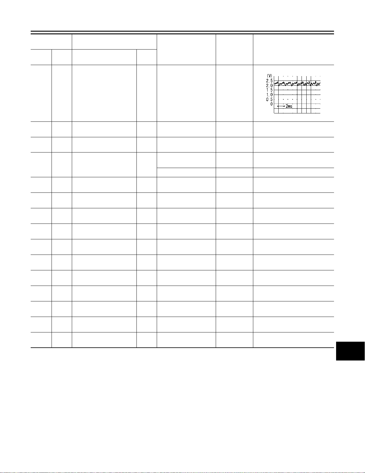
< ECU DIAGNOSIS INFORMATION >
AUDIO UNIT
[BASE AUDIO]
Terminal
(Wire color)
+ – Signal name
37
(W)
38
(—)
43
(B)
45
(W)
46
(SB)
47
(LG)
48
(SB)
49
(LG)
67
(—)
68
(—)
70
(—)
71
(—)
72
(—)
73
(—)
74
(—)
38
Microphone signal Input
(—)
— Microphone ground — — — —
—EQ 1 — — — 0 V
Groun
Groun
Auto ACC input signal Input
d
AV communication signal
—
(H)
AV communication signal
—
(L)
AV communication signal
—
(H)
AV communication signal
—
(L)
— Antenna amp. ON signal Output [Ignition switch ON] 7.0 - 16.0 V 12.0 V
Antenna signal Input [Ignition switch ON] 7.0 - 16.0 V 12.0 V
d
— USB ground — — — —
— V BUS signal — — 4.75 - 5.25 V 5.0 V
— USB D- signal — — — —
— USB D+ signal — — — —
— Shield — — — —
*1: Models with 4 speakers
*2: Models with 6 speakers
Description
Input/
Output
Input/
output
Input/
output
Input/
output
Input/
output
Condition Standard
The value between the
maximum in[Ignition switch ON]
Give a voice.
[Ignition switch ON or
ACC]
[Ignition switch OFF] — 3.15 V
—— —
—— —
—— —
—— —
put voltage
and the mini-
mum input
voltage is
4.72V or less.
— 0 – 0.5 V
Reference value
(Approx.)
PKIB5037J
A
B
C
D
E
F
G
H
I
J
K
L
M
AV
AV-23
O
P
Page 29
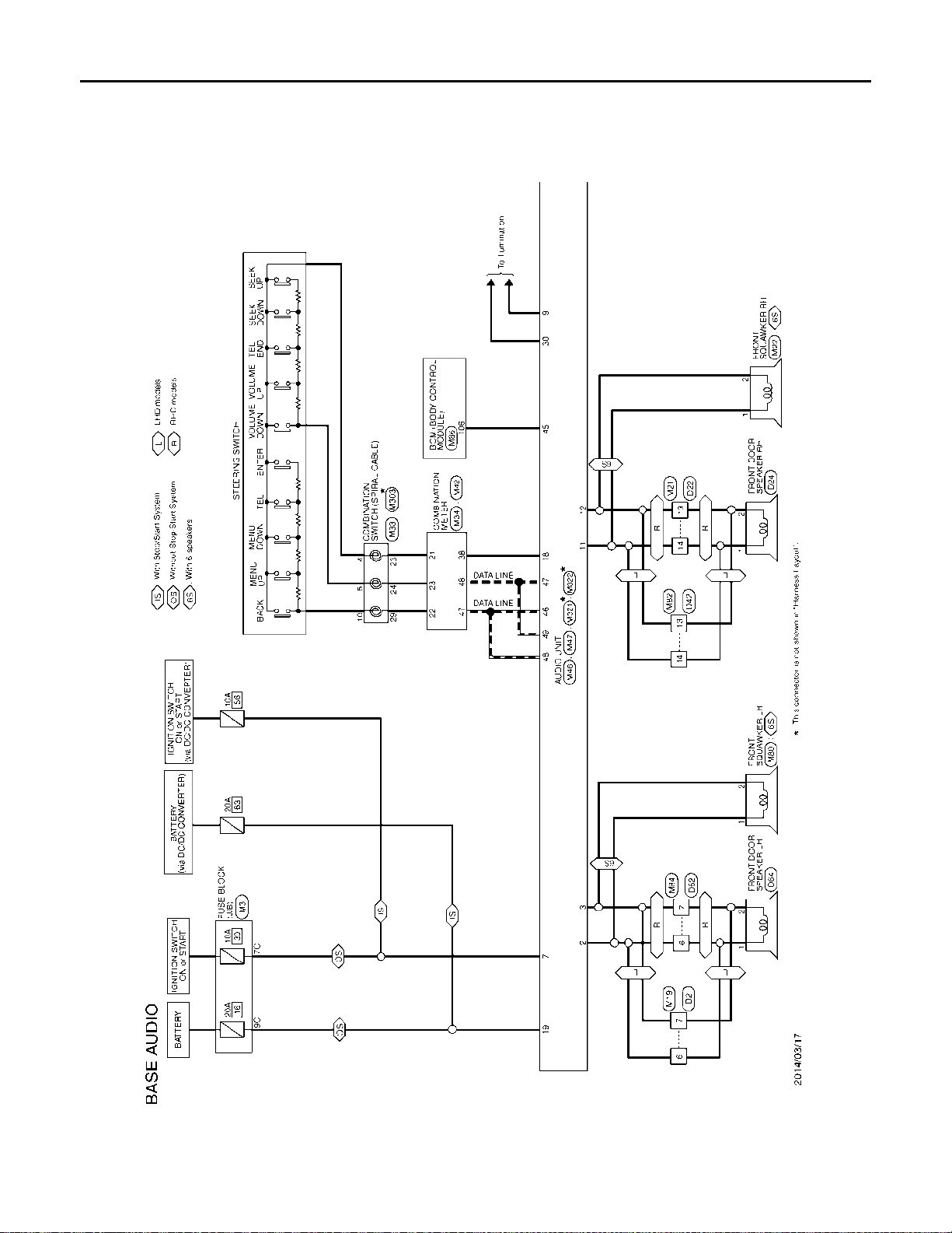
BASE AUDIO
< WIRING DIAGRAM >
[BASE AUDIO]
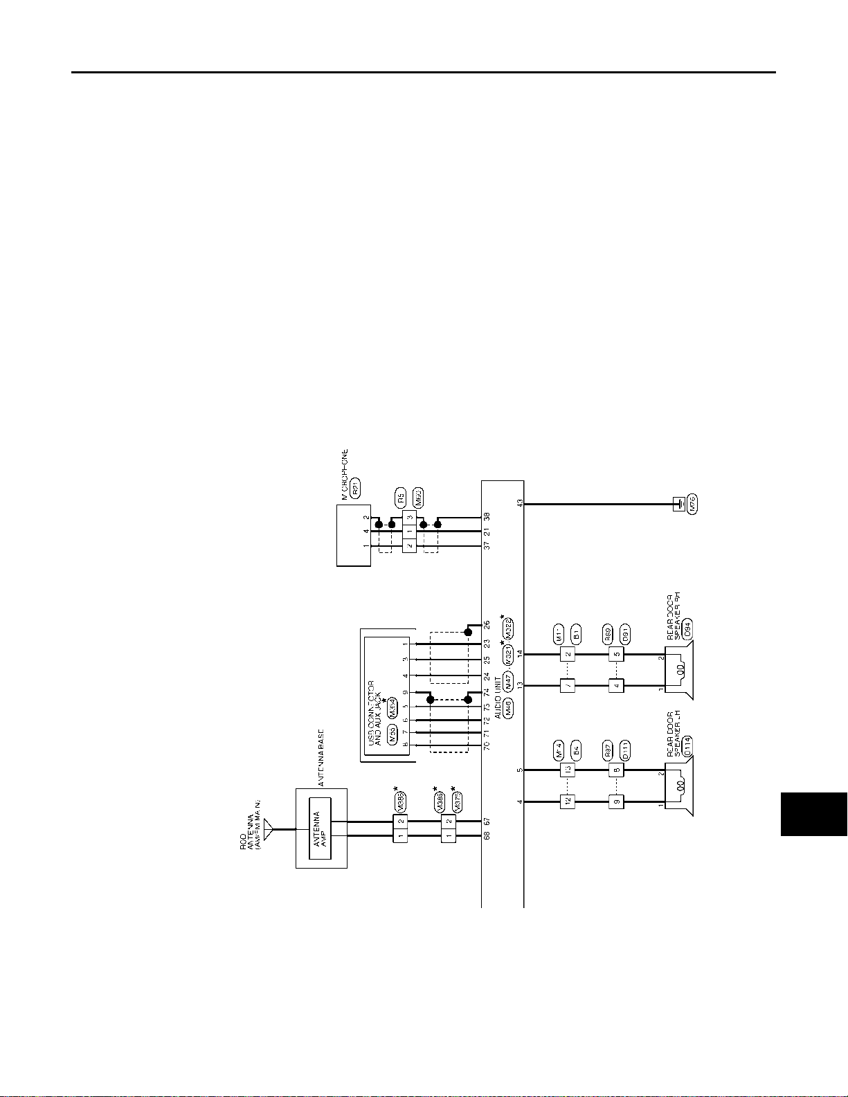
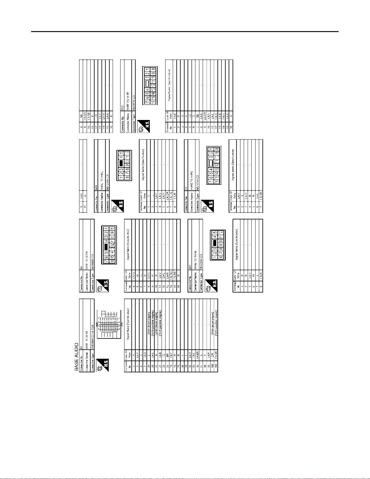
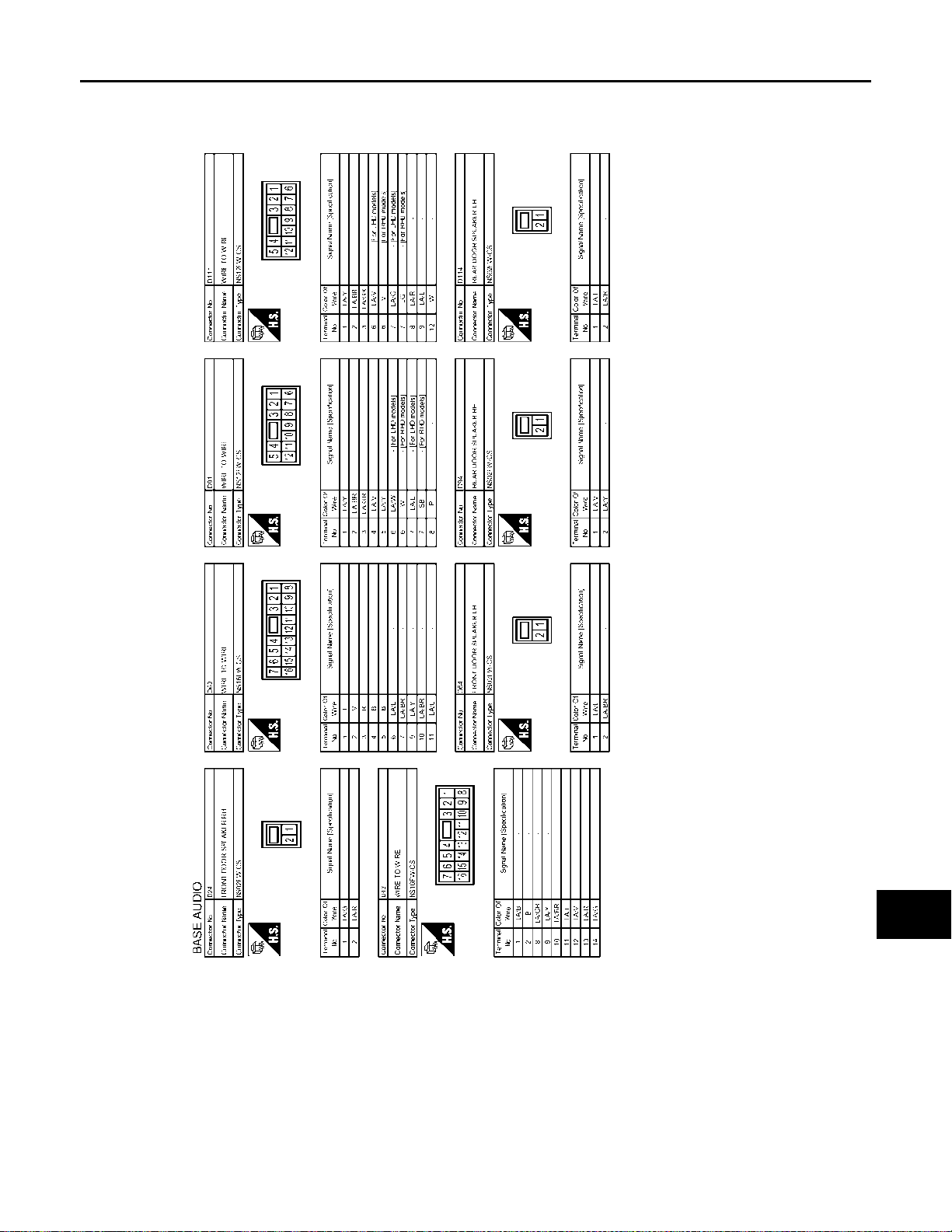
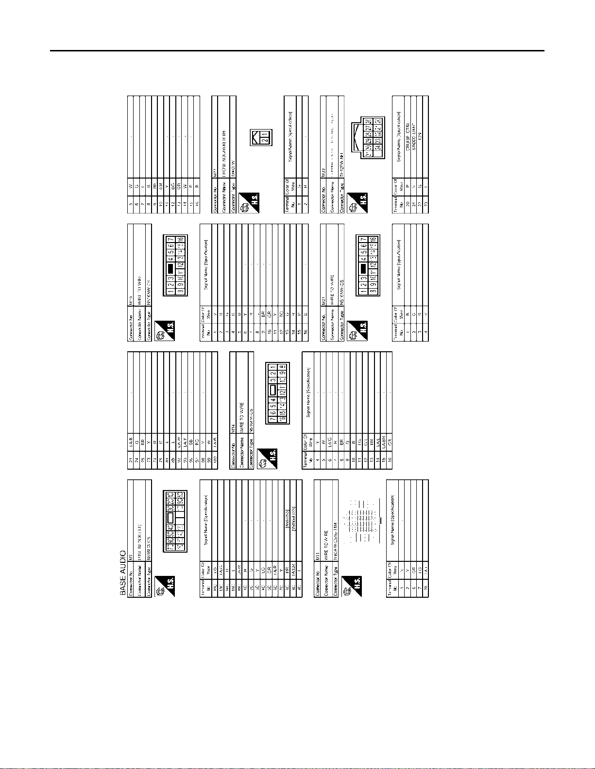
WIRING DIAGRAM
BASE AUDIO
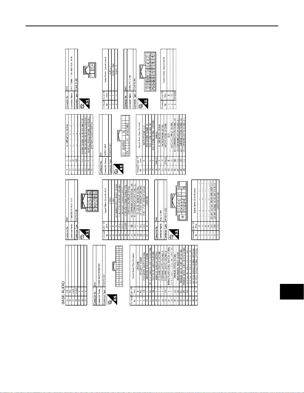
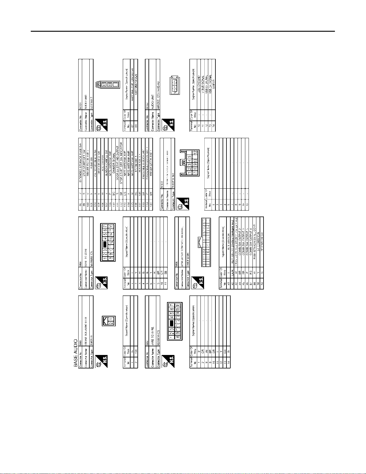
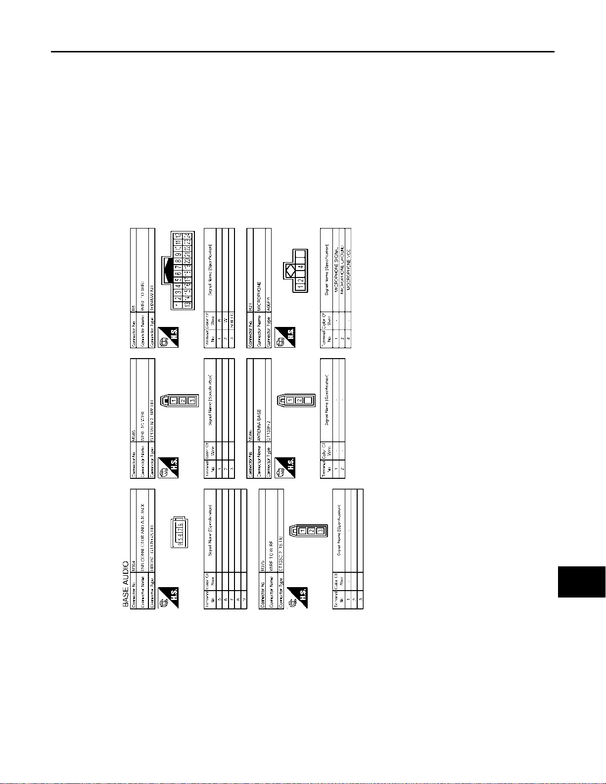
Wiring Diagram INFOID:0000000010714757
AV-24
JRNWD4104GB
Page 30
< WIRING DIAGRAM >
BASE AUDIO
[BASE AUDIO]
A
B
C
D
E
F
G
AV
H
I
J
K
L
M
O
AV-25
JRNWD4105GB
P
Page 31
< WIRING DIAGRAM >
BASE AUDIO
[BASE AUDIO]
AV-26
JRNWD4106GB
Page 32
< WIRING DIAGRAM >
BASE AUDIO
[BASE AUDIO]
A
B
C
D
E
F
G
AV
H
I
J
K
L
M
O
AV-27
JRNWD4107GB
P
Page 33
< WIRING DIAGRAM >
BASE AUDIO
[BASE AUDIO]
AV-28
JRNWD4108GB
Page 34
< WIRING DIAGRAM >
BASE AUDIO
[BASE AUDIO]
A
B
C
D
E
F
G
AV
H
I
J
K
L
M
O
AV-29
JRNWD4109GB
P
Page 35
< WIRING DIAGRAM >
BASE AUDIO
[BASE AUDIO]
AV-30
JRNWD4110GB
Page 36
< WIRING DIAGRAM >
BASE AUDIO
[BASE AUDIO]
A
B
C
D
E
F
G
AV
H
I
J
K
L
M
O
AV-31
JRNWD4111GB
P
Page 37
DIAGNOSIS AND REPAIR WORK FLOW
< BASIC INSPECTION >
[BASE AUDIO]
BASIC INSPECTION
DIAGNOSIS AND REPAIR WORK FLOW
Work Flow INFOID:0000000010714758
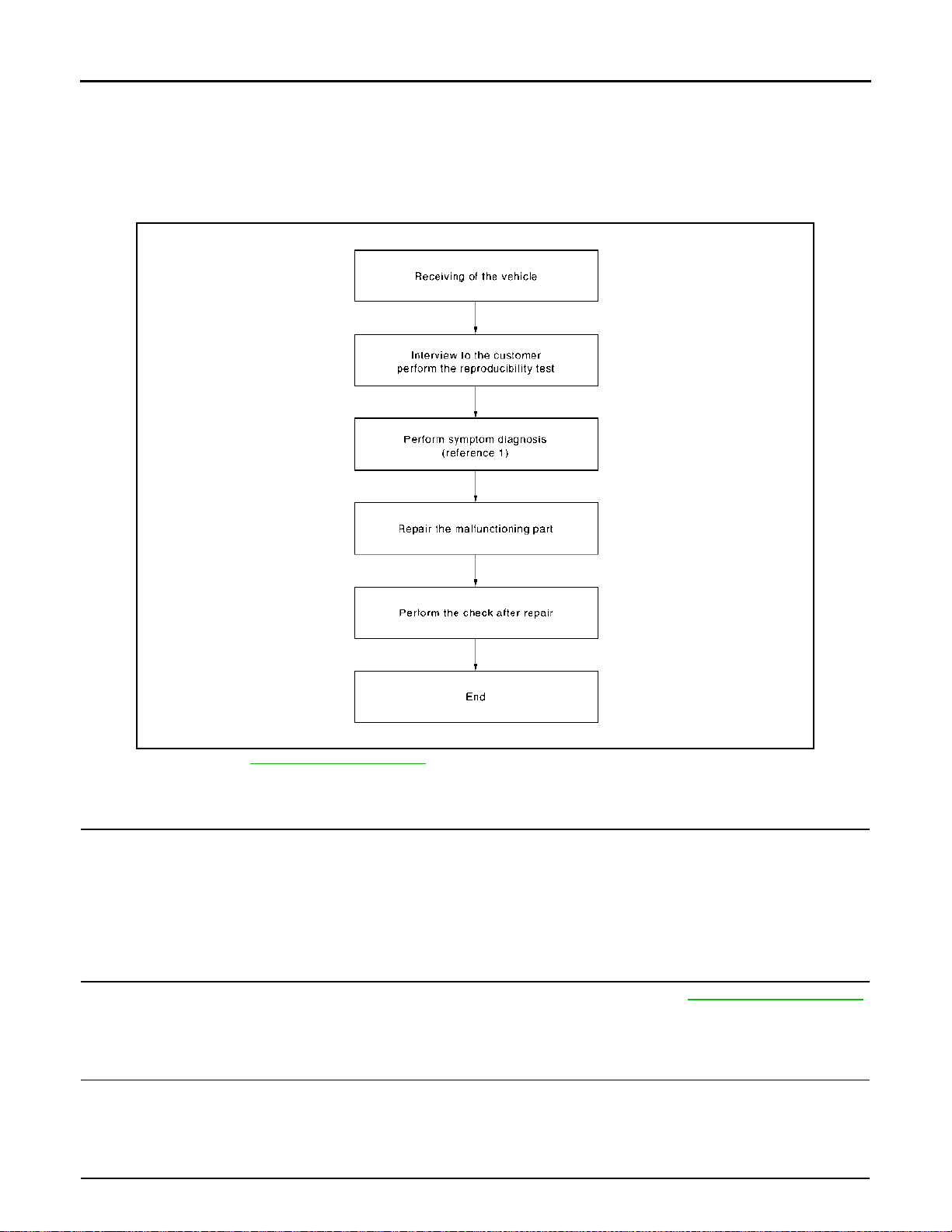
OVERALL SEQUENCE
JSNIA0669GB
Reference 1··· Refer to AV-46, "Symptom Table".
DETAILED FLOW
1.CHECK SYMPTOM
Check the malfunction symptoms by performing the following items.
• Interview the customer to obtain the malfunction information (conditions and environment when the malfunction occurred).
• Check the symptom.
>> GO TO 2.
2.PERFORM DIAGNOSIS BY SYMPTOM
Perform the relevant diagnosis referring to the diagnosis chart by symptom. Refer to AV-46, "
>> GO TO 3.
Symptom Table".
3.REPAIR OR REPLACE MALFUNCTIONING PARTS
Repair or replace the malfunctioning parts.
>> GO TO 4.
4.FINAL CHECK
AV-32
Page 38

DIAGNOSIS AND REPAIR WORK FLOW
< BASIC INSPECTION >
Perform the operation to check that the malfunction symptom is solved or any other symptoms are present.
Is there any symptom?
YES >> GO TO 2.
NO >> INSPECTION END
[BASE AUDIO]
A
B
C
D
E
F
G
AV
H
I
J
K
L
M
O
AV-33
P
Page 39
POWER SUPPLY AND GROUND CIRCUIT
< DTC/CIRCUIT DIAGNOSIS >
[BASE AUDIO]
DTC/CIRCUIT DIAGNOSIS
POWER SUPPLY AND GROUND CIRCUIT
AUDIO UNIT
AUDIO UNIT : Diagnosis Procedure INFOID:0000000010714759
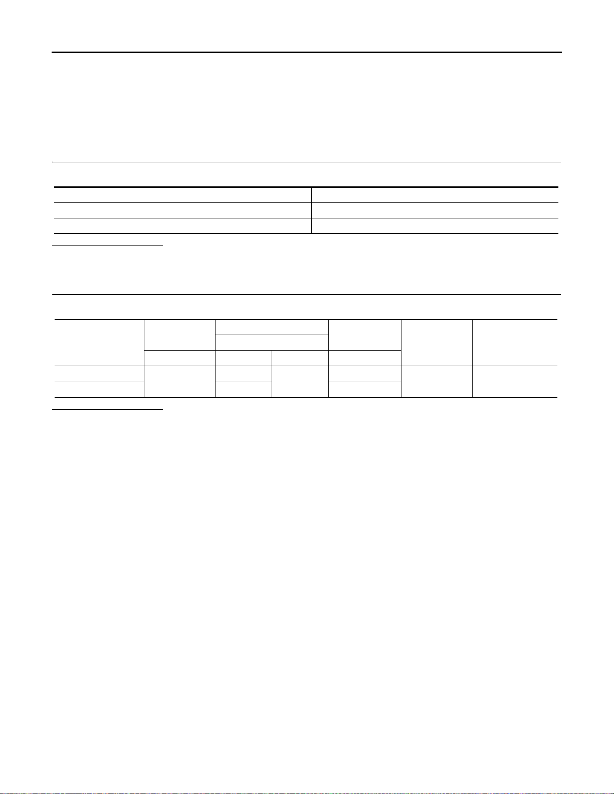
1.CHECK FUSE
Check for blown fuses.
Power source Fuse No.
Battery 19
Ignition switch ON or START 7
Is inspection result OK?
YES >> GO TO 2.
NO >> Be sure to eliminate cause of malfunction before installing new fuse.
2.CHECK POWER SUPPLY CIRCUIT
Check voltage between audio unit harness connector and ground.
19
Probe
Ground
Signal name
Battery power supply
Ignition power supply 7 ON
Is inspection result OK?
YES >> INSPECTION END
NO >> Check harness between audio unit and fuse.
Audio unit
Connector (+) (−) Ignition switch
M46
Condition
OFF
Standard Reference valueTerminal
9.0 - 16.0 V Battery voltage
AV-34
Page 40
< DTC/CIRCUIT DIAGNOSIS >
AV COMMUNICATION CIRCUIT
[BASE AUDIO]
AV COMMUNICATION CIRCUIT
Diagnosis Procedure INFOID:0000000010714760
NOTE:
• The auto ACC function allows the accessory power supply for a certain period of time even after ignition
switch OFF. For this reason, when performing diagnosis, turn the ignition switch OFF and wait for 3 minutes
with the driver's door opened.
• The operation of the vehicle during standby may cause an accessory power supply.
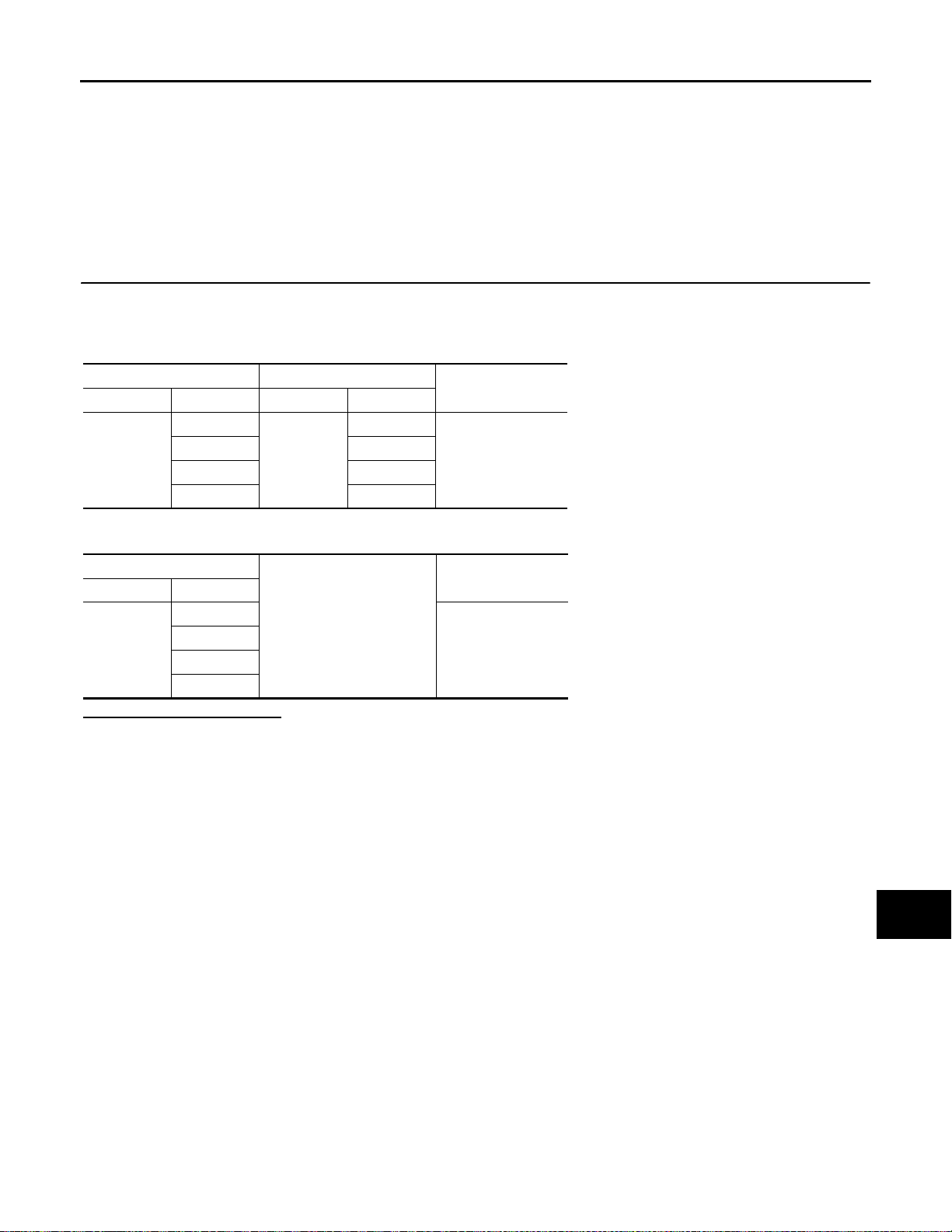
1.CHECK CONTINUITY AV COMMUNICATION CIRCUIT
1. Turn ignition switch OFF.
2. Disconnect audio unit connector and combination meter connector.
3. Check continuity between audio unit harness connector and combination meter harness connector.
Audio unit Combination meter
Connector Terminal Connector Terminal
M47
46
47 48
48 47
49 48
M42
47
4. Check continuity between audio unit harness connector and ground.
Audio unit
Connector Terminal
M47
46
47
48
49
Ground
Is inspection result normal?
YES >> INSPECTION END
NO >> Repair harness or connector.
Continuity
Existed
Continuity
Not existed
A
B
C
D
E
F
G
H
I
J
K
AV-35
L
M
AV
O
P
Page 41
VEHICLE SPEED SIGNAL CIRCUIT
< DTC/CIRCUIT DIAGNOSIS >
[BASE AUDIO]
VEHICLE SPEED SIGNAL CIRCUIT
Component Function Check INFOID:0000000010714761
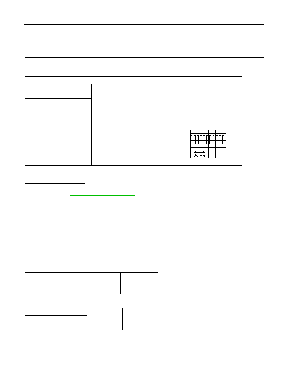
1.VEHICLE SPEED FUNCTION
1. Turn ignition switch ON.
2. Check the voltage between audio unit harness connector and ground.
Terminals
(+)
Connector Terminal
M46 18 Ground
(−)Audio unit
Condition
The maximum voltage varies de-
pending on the specification (desti-
Speedometer operated
[When vehicle speed is
approx. 40 km/h (25
MPH)]
Reference value
(Approx.)
NOTE:
nation unit).
JSNIA0012GB
CAUTION:
Always drive safely.
Is inspection result normal?
YES >> INSPECTION END
NO >> Refer to AV -36, "
Diagnosis Procedure".
Diagnosis Procedure INFOID:0000000010714762
NOTE:
• The auto ACC function allows the accessory power supply for a certain period of time even after ignition
switch OFF. For this reason, when performing diagnosis, turn the ignition switch OFF and wait for 3 minutes
with the driver's door opened.
• The operation of the vehicle during standby may cause an accessory power supply.
1.CHECK VEHICLE SPEED SIGNAL CIRCUIT
1. Turn ignition switch OFF.
2. Disconnect audio unit harness connector and combination meter harness connector.
3. Check continuity between audio unit harness connector and combination meter harness connector.
Audio unit Combination meter
Connector Terminal Connector Terminal
M46 18 M34 38 Existed
4. Check continuity between audio unit harness connector and ground.
Continuity
Audio unit
Connector Terminal
M46 18 Not existed
Ground
Is the inspection result normal?
YES >> GO TO 2.
NO >> Repair harness or connector.
2.CHECK DTC WITH “METER/M&A”
Continuity
AV-36
Page 42

VEHICLE SPEED SIGNAL CIRCUIT
< DTC/CIRCUIT DIAGNOSIS >
Perform “Self Diagnostic Result” of “METER/M&A” with CONSULT. Refer to MWI-86, "CONSULT Function".
Is any DTC detected?
YES >> Repair or replace malfunctioning parts.
NO >> Replace combination meter. Refer to MWI-151, "
Removal and Installation".
[BASE AUDIO]
A
B
C
D
E
F
G
AV
H
I
J
K
L
M
O
AV-37
P
Page 43

MICROPHONE SIGNAL CIRCUIT
< DTC/CIRCUIT DIAGNOSIS >
[BASE AUDIO]
MICROPHONE SIGNAL CIRCUIT
Description INFOID:0000000010957773
Audio unit supplies power to microphone. The microphone transmits the sound voice to the audio unit.
Diagnosis Procedure INFOID:0000000010957774
NOTE:
• The auto ACC function allows the accessory power supply for a certain period of time even after ignition
switch OFF. For this reason, when performing diagnosis, turn the ignition switch OFF and wait for 3 minutes
with the driver's door opened.
• The operation of the vehicle during standby may cause an accessory power supply.
1.CHECK CONTINUITY BETWEEN AUDIO UNIT AND MICROPHONE CIRCUIT
1. Turn ignition switch OFF.
2. Disconnect audio unit harness connector and microphone harness connector.
3. Check the continuity between audio unit harness connector and microphone harness connector.
Audio unit Microphone
Connector Terminal Connector Terminal
37
M47
38 2
R21
4. Check continuity between audio unit harness connector and ground.
audio unit
Connector Terminal
M47
37
21
Ground
Is inspection result OK?
YES >> GO TO 2.
NO >> Repair harness or connector.
2.CHECK VOLTAGE MICROPHONE VCC
1. Connect audio unit harness connector.
2. Turn ignition switch ON.
3. Check the voltage between audio unit harness connector and ground.
(+)
Audio unit
Connector Terminal
M47 21 Ground — 5.0 V
(–) Standard
Is inspection result OK?
YES >> GO TO 3.
NO >> Replace audio unit. Refer to AV-51, "
Removal and Installation".
3.CHECK MICROPHONE SIGNAL
Continuity
1
Existed21 4
Continuity
Not existed
Voltage
(Approx.)
1. Turn ignition switch OFF.
2. Connect microphone harness connector.
3. Turn ignition switch ON.
4. Check the signal between audio unit harness connector.
AV-38
Page 44
< DTC/CIRCUIT DIAGNOSIS >
MICROPHONE SIGNAL CIRCUIT
[BASE AUDIO]
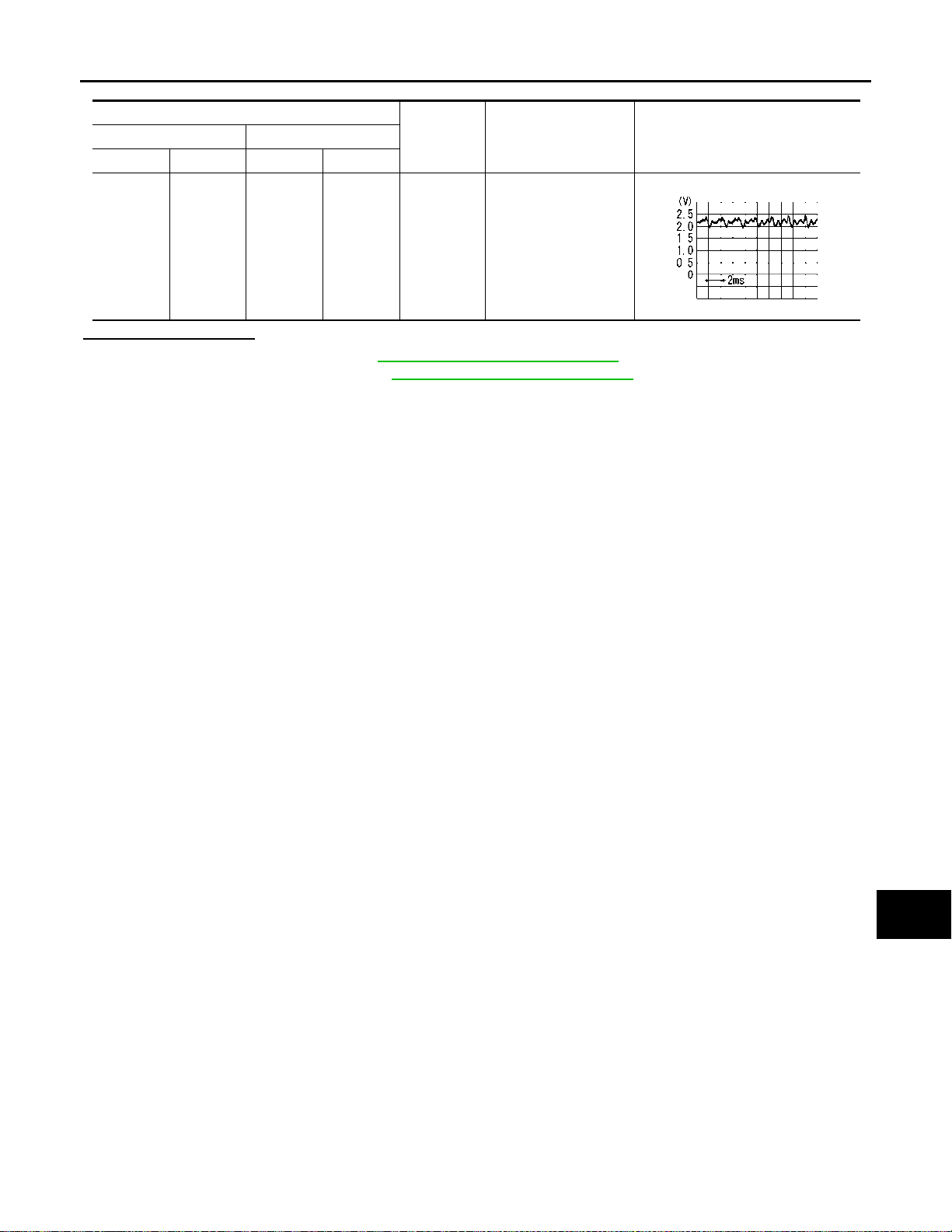
Audio unit
Condition Standard Reference value(+) (–)
Connector Terminal Connector Terminal
The value between the
maximum input voltage
and the minimum input
voltage is 4.72V or
less.
M47 37 M47 38
Give a
voice.
Is inspection result OK?
YES >> Replace audio unit. Refer to AV-51, "Removal and Installation".
NO >> Replace microphone. Refer to AV-56, "
Removal and Installation".
PKIB5037J
A
B
C
D
E
F
G
H
AV
I
J
K
L
M
O
P
AV-39
Page 45

STEERING SWITCH SIGNAL A CIRCUIT
< DTC/CIRCUIT DIAGNOSIS >
[BASE AUDIO]
STEERING SWITCH SIGNAL A CIRCUIT
Diagnosis Procedure INFOID:0000000010714763
1.CHECK STEERING SWITCH SIGNAL A CIRCUIT
1. Turn ignition switch OFF.
2. Disconnect combination meter harness connector and spiral cable harness connector.
3. Check continuity between combination meter harness connector and spiral cable harness connector.
Combination meter Spiral cable
Connector Terminal Connector Terminal
M34 22 M33 29 Existed
Continuity
4. Check continuity between combination meter harness connector and ground.
Combination meter
Connector Terminal
M34 22 Not existed
Ground
Continuity
Is the inspection result normal?
YES >> GO TO 2.
NO >> Repair harness or connector.
2.CHECK SPIRAL CABLE
1. Disconnect steering switch connector .
2. Check continuity between spiral cable harness connectors.
Spiral cable
Connector Terminal Connector Terminal
M33 29 M303 10 Existed
Continuity
Is the inspection result normal?
YES >> GO TO 3.
NO >> Replace spiral cable. Refer to SR-23, "
Removal and Installation".
3.CHECK COMBINATION METER VOLTAGE
1. Connect combination meter harness connector, steering switch connector and spiral cable connector.
2. Turn ignition switch ON.
3. Check the voltage between combination meter harness connector.
Combination meter
Connector
M34 22 21
+-
Terminal
Condition
Keep pressing BACK switch 0 V
Keep pressing MENU UP switch 0.5 V
Keep pressing MENU DOWN switch 1.2 V
Keep pressing TEL switch 2.1 V
Keep pressing ENTER switch 3.3 V
Voltage
(Approx.)
Is the inspection result normal?
YES >> GO TO 4.
NO >> Replace combination meter. Refer to MWI-151, "
Removal and Installation".
4.CHECK STEERING SWITCH
1. Turn ignition switch OFF.
AV-40
Page 46
STEERING SWITCH SIGNAL A CIRCUIT
< DTC/CIRCUIT DIAGNOSIS >
2. Check steering switch. Refer to AV-41, "Component Inspection".
Is the inspection result normal?
YES >> INSPECTION END
NO >> Replace steering switch. Refer to AV-57, "
Removal and Installation".
[BASE AUDIO]
Component Inspection INFOID:0000000010714764
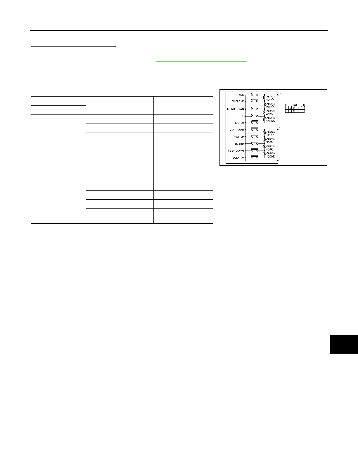
A
B
Measure the resistance between the steering switch connector.
Steering switch
Terminal Terminal
10
4
5
Condition
ENTER switch is pressed 1982 – 2064
TEL switch is pressed 708 – 738
MENU DOWN switch is
pressed
MENU UP switch is pressed 118 – 124
BACK switch is pressed 0
SEEK UP switch is pressed 1982 – 2064
SEEK DOWN switch is
pressed
TEL END switch is pressed 314 – 328
VOL UP switch is pressed 118 – 124
VOL DOWN switch is
pressed
Resistance
(Approx.) Ω
314 – 328
708 – 738
0
JSNIA7127GB
C
D
E
F
G
H
I
J
AV
K
L
M
O
P
AV-41
Page 47

STEERING SWITCH SIGNAL B CIRCUIT
< DTC/CIRCUIT DIAGNOSIS >
[BASE AUDIO]
STEERING SWITCH SIGNAL B CIRCUIT
Diagnosis Procedure INFOID:0000000010714765
1.CHECK STEERING SWITCH SIGNAL B CIRCUIT
1. Turn ignition switch OFF.
2. Disconnect combination meter harness connector and spiral cable harness connector.
3. Check continuity between combination meter harness connector and spiral cable harness connector.
Combination meter Spiral cable
Connector Terminal Connector Terminal
M34 23 M33 24 Existed
Continuity
4. Check continuity between combination meter harness connector and ground.
Combination meter
Connector Terminal
M34 23 Not existed
Ground
Continuity
Is the inspection result normal?
YES >> GO TO 2.
NO >> Repair harness or connector.
2.CHECK SPIRAL CABLE
1. Disconnect steering switch connector .
2. Check continuity between spiral cable harness connectors.
Spiral cable
Connector Terminal Connector Terminal
M33 24 M303 5 Existed
Continuity
Is the inspection result normal?
YES >> GO TO 3.
NO >> Replace spiral cable. Refer to SR-23, "
Removal and Installation".
3.CHECK COMBINATION METER VOLTAGE
1. Connect combination meter harness connector, steering switch connector and spiral cable connector.
2. Turn ignition switch ON.
3. Check the voltage between combination meter harness connector.
Combination meter
Connector
M34 23 21
+-
Terminal
Condition
Keep pressing VOLUME DOWN switch 0 V
Keep pressing VOLUME UP switch 0.5 V
Keep pressing TEL END switch 1.2 V
Keep pressing SEEK DOWN switch 2.1 V
Keep pressing SEEK UP switch 3.3 V
Voltage
(Approx.)
Is the inspection result normal?
YES >> GO TO 4.
NO >> Replace combination meter. Refer to MWI-151, "
Removal and Installation".
4.CHECK STEERING SWITCH
1. Turn ignition switch OFF.
AV-42
Page 48
STEERING SWITCH SIGNAL B CIRCUIT
< DTC/CIRCUIT DIAGNOSIS >
2. Check steering switch. Refer to AV-43, "Component Inspection".
Is the inspection result normal?
YES >> INSPECTION END
NO >> Replace steering switch. Refer to AV-57, "
Removal and Installation".
[BASE AUDIO]
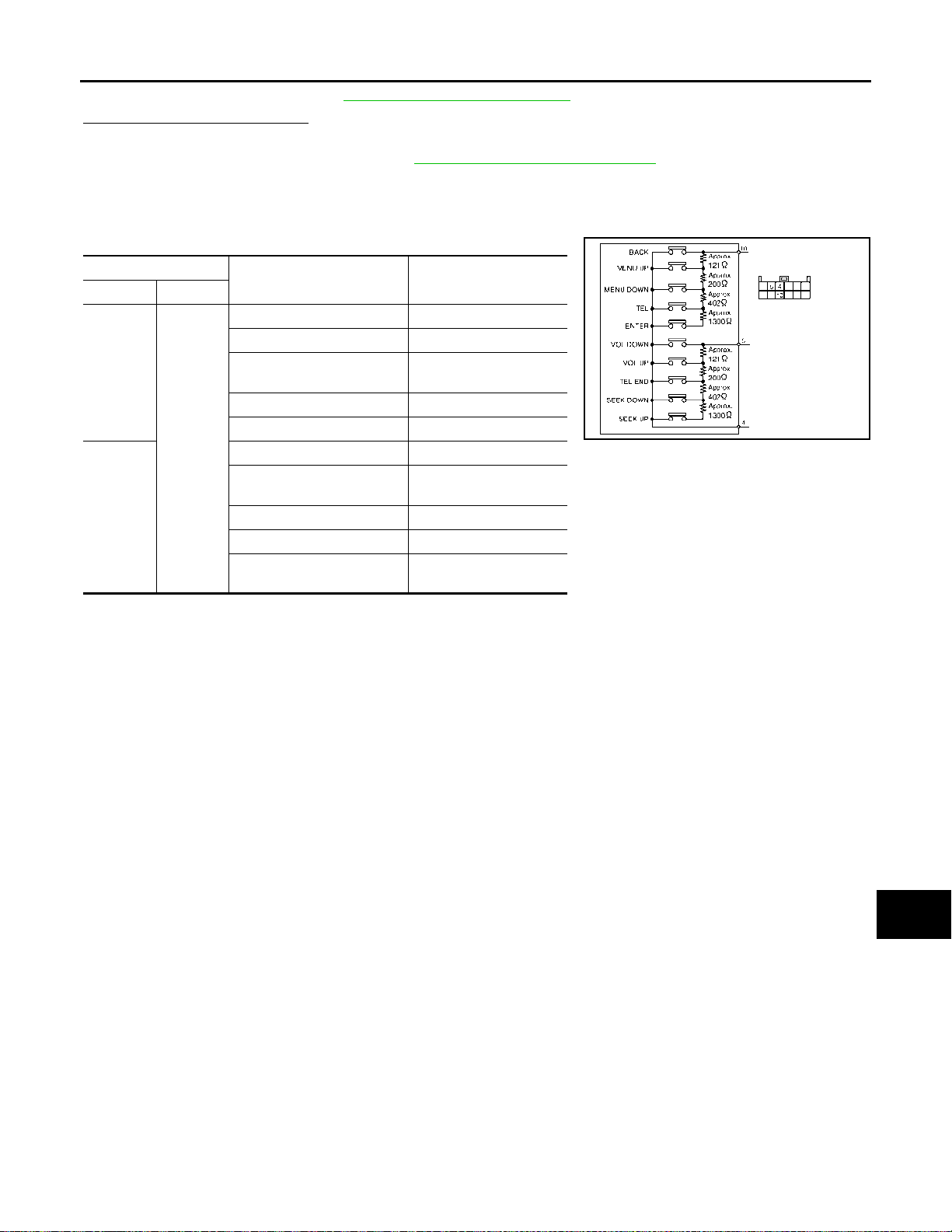
Component Inspection INFOID:0000000010714766
A
B
Measure the resistance between the steering switch connector.
Steering switch
Terminal Terminal
10
4
5
Condition
ENTER switch is pressed 1982 – 2064
TEL switch is pressed 708 – 738
MENU DOWN switch is
pressed
MENU UP switch is pressed 118 – 124
BACK switch is pressed 0
SEEK UP switch is pressed 1982 – 2064
SEEK DOWN switch is
pressed
TEL END switch is pressed 314 – 328
VOL UP switch is pressed 118 – 124
VOL DOWN switch is
pressed
Resistance
(Approx.) Ω
314 – 328
708 – 738
0
JSNIA7127GB
C
D
E
F
G
H
I
J
AV
K
L
M
O
P
AV-43
Page 49

STEERING SWITCH SIGNAL GND CIRCUIT
< DTC/CIRCUIT DIAGNOSIS >
[BASE AUDIO]
STEERING SWITCH SIGNAL GND CIRCUIT
Description INFOID:0000000010714767
Transmits the steering switch signal to audio unit.
Diagnosis Procedure INFOID:0000000010714768
1.CHECK STEERING SWITCH SIGNAL GROUND CIRCUIT
1. Turn ignition switch OFF.
2. Disconnect combination meter harness connector and spiral cable harness connector.
3. Check continuity between combination meter harness connector and spiral cable harness connector.
Combination meter Spiral cable
Connector Terminal Connector Terminal
M34 21 M33 23 Existed
Is the inspection result normal?
YES >> GO TO 2.
NO >> Repair harness or connector.
Continuity
2.CHECK SPIRAL CABLE
1. Disconnect steering switch connector .
2. Check continuity between spiral cable harness connectors.
Spiral cable
Connector Terminal Connector Terminal
M33 23 M303 4 Existed
Is the inspection result normal?
YES >> GO TO 3.
NO >> Replace spiral cable. Refer to SR-23, "
Continuity
Removal and Installation".
3.CHECK STEERING SWITCH
Check steering switch. Refer to AV-44, "
Is the inspection result normal?
YES >> INSPECTION END
NO >> Replace steering switch. Refer to AV-57, "
Component Inspection".
Removal and Installation".
Component Inspection INFOID:0000000010714769
Measure the resistance between the steering switch connector.
AV-44
Page 50
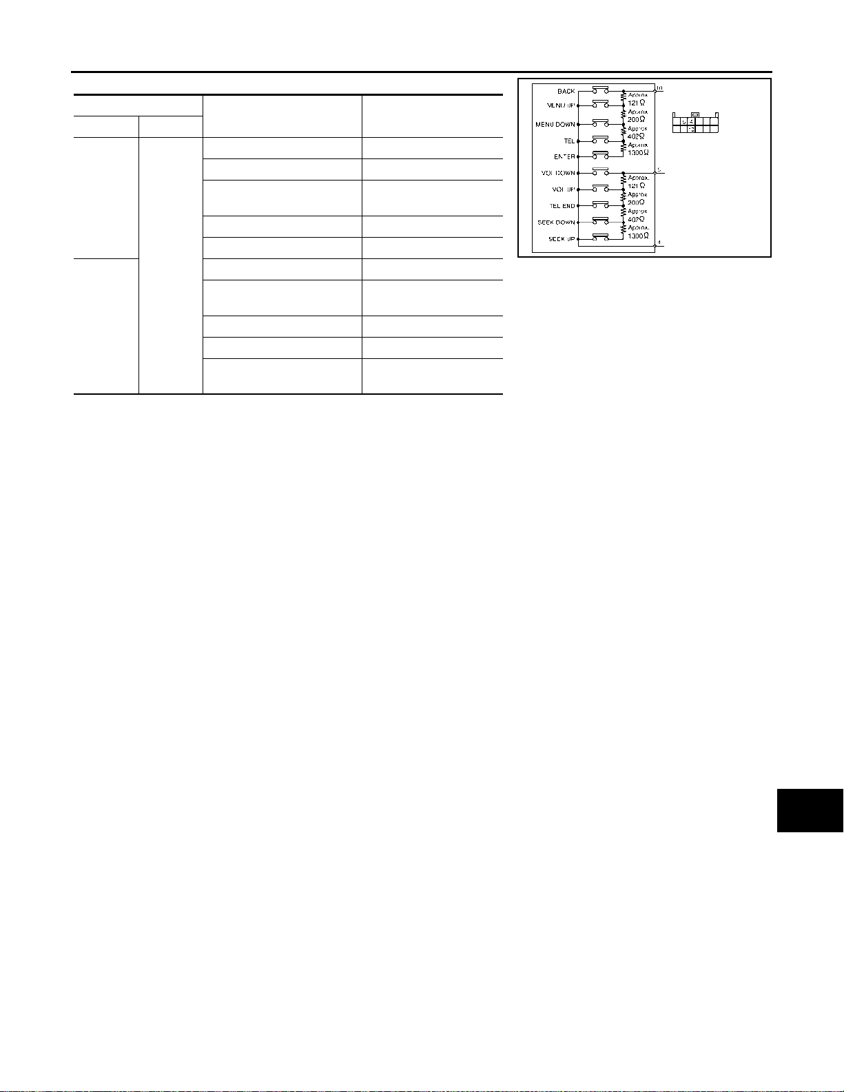
STEERING SWITCH SIGNAL GND CIRCUIT
< DTC/CIRCUIT DIAGNOSIS >
[BASE AUDIO]
Steering switch
Terminal Terminal
10
4
5
Condition
ENTER switch is pressed 1982 – 2064
TEL switch is pressed 708 – 738
MENU DOWN switch is
pressed
MENU UP switch is pressed 118 – 124
BACK switch is pressed 0
SEEK UP switch is pressed 1982 – 2064
SEEK DOWN switch is
pressed
TEL END switch is pressed 314 – 328
VOL UP switch is pressed 118 – 124
VOL DOWN switch is
pressed
Resistance
(Approx.) Ω
314 – 328
708 – 738
0
A
B
C
JSNIA7127GB
D
E
F
G
H
AV
I
J
K
L
M
O
P
AV-45
Page 51

AUDIO SYSTEM SYMPTOMS
< SYMPTOM DIAGNOSIS >
[BASE AUDIO]
SYMPTOM DIAGNOSIS
AUDIO SYSTEM SYMPTOMS
Symptom Table INFOID:0000000010714770
RELATED TO AUDIO SYSTEM
Symptoms Check items Possible malfunction location / Action to take
Audio unit does not start. —
No sound from all speakers.
No sound comes out.
Noise is mixed with audio.
Radio is not received or poor reception.
The function automatically adjusting volume (speed sensitive
volume) does not operate due
to the change in vehicle speed.
(Volume can be controlled with
the volume control knob.)
Only a certain speaker (front right,
front left, rear right, or rear left, etc.)
does not output sound.
Noise comes out from all speaker. Malfunction in audio unit.
Noise comes out only from a certa in
speaker (front right, front left, rear
right, or rear left, etc.).
Noise is mixed with radio only
(when the car hits a bump or while
driving over bad roads).
• Other audio sounds are normal.
• Any radio cannot be received or
poor reception is caused even after moving to a service area with
good reception (e.g. a place with
clear view and no obstacles generating external noises).
—
Audio unit power supply and ground circuit.
Refer to AV-3 4, "
Audio unit power supply and ground circuit.
Refer to AV-3 4, "
• Poor connector connection of speaker.
• Sound signal circuit malfunction between audio unit and
speaker.
• Malfunction in speaker.
• Malfunction in audio unit.
• Poor connector connection of speaker.
• Sound signal circuit malfunction between audio unit and
speaker.
• Malfunction in speaker.
• Poor installation of speaker (e.g. backlash and looseness)
• Malfunction in audio unit.
Poor connector connection of antenna or antenna feeder.
• Antenna amp. ON signal circuit malfunctio n.
• Poor connector connection of antenna or antenna feeder.
• Vehicle speed signal circuit.
Refer to AV-36, "
• Malfunction in audio unit.
Refer to AV-51, "
AUDIO UNIT : Diagnosis Procedure".
AUDIO UNIT : Diagnosis Procedure".
Component Function Check".
Removal and Installation".
RELATED TO USB
NOTE:
Check that there is no malfunction of USB equipment main body before performing a diagnosis.
Symptoms Check items
iPod or USB memory can not be
recognized.
With iPod or USB
memory Connected,
check “USB connected” in diagnostic function of audio unit.
“Yes” is display for “USB
connected”.
“No” is display for “USB connected”.
Probable malfunction location / Action
to take
iPod or USB memory
• USB and AUX harness
• USB connector and AUX jack
• Audio unit
iPod is a trademark of Apple inc., registered in the U.S. and other countries.
RELATED TO AUXILIARY INPUT
NOTE:
Check that there is no malfunction of AUX equipment main body before performing a diagnosis.
AV-46
Page 52

< SYMPTOM DIAGNOSIS >
AUDIO SYSTEM SYMPTOMS
[BASE AUDIO]
Symptoms Check items Probable malfunction location
No voice sound is heard when
AUX mode is selected.
Voice sound is heard when other modes
are selected.
• USB and AUX harness
• USB connector and AUX jack
RELATED TO STEERING SWITCH
Symptoms Possible malfunction location / Action to take
All steering switches are not operated.
Only specified switch cannot be operated. Replace steering switch. Refer to AV-57, "
“BACK”, “MENU UP”, “MENU DOWN”, “TEL” and “ENTER”
switches are not operated.
“VOL DOWN”, “VOL UP”, “TEL END”, “SEEK DOWN” and
“SEEK UP” switches are not operated.
Steering switch signal ground circuit. Refer to AV-44, "Diagnosis Pro-
cedure".
Steering switch signal A circuit.
Refer to AV-40, "
Steering switch signal B circuit.
Refer to AV-42, "
Diagnosis Procedure".
Diagnosis Procedure".
A
B
C
Removal and Installation".
D
E
F
G
H
AV
I
J
K
L
M
O
P
AV-47
Page 53

HANDS-FREE PHONE SYMPTOMS
< SYMPTOM DIAGNOSIS >
[BASE AUDIO]
HANDS-FREE PHONE SYMPTOMS
Symptom Table INFOID:0000000010957799
RELATED TO HANDS-FREE PHONE
Symptoms Check items Possible malfunction location/Action to take
Does not recognize cellular
phone connection.
Hands-free phone cannot be
established.
The other party's voice cannot
be heard by hands-free phone.
RELATED TO STEERING SWITCH
Symptoms Possible malfunction location / Action to take
All steering switches are not operated.
Only specified switch cannot be operated. Replace steering switch. Refer to AV-57, "
“BACK”, “MENU UP”, “MENU DOWN”, “TEL” and “ENTER”
switches are not operated.
“VOL DOWN”, “VOL UP”, “TEL END”, “SEEK DOWN” and
“SEEK UP” switches are not operated.
Repeat the registration of cellular phone. Audio unit
—
Audio system sound is normal. Sound signal (TEL voice, TEL gu id anc e ) circu it
Audio system sound does not sound. Refer to AV-46, "
Steering switch signal ground circuit. Refer to AV-44, "Diagnosis Pro-
cedure".
Steering switch signal A circuit.
Refer to AV-40, "
Steering switch signal B circuit.
Refer to AV-42, "
Audio unit power supply and ground circuit.
Refer to AV-34, "
Diagnosis Procedure".
Diagnosis Procedure".
AUDIO UNIT : Diagnosis Procedure".
Symptom Table".
Removal and Installation".
AV-48
Page 54

< SYMPTOM DIAGNOSIS >
NORMAL OPERATING CONDITION
[BASE AUDIO]
NORMAL OPERATING CONDITION
Description INFOID:0000000010714771
RELATED TO AUDIO
• The majority of the audio malfunctions are the result of outside causes (bad CD, electromagnetic interference, etc.). Check the symptoms below to diagnose the malfunction.
• The vehicle itself can be a source of noise if noise prevention parts or electrical equipment is malfunctioning.
Check that noise is caused and/or changed by engine speed, ignition switch turned to each position, and
operation of each piece of electrical equipment. Then determine the cause.
NOTE:
• CD-R is not guaranteed to play because they can contain compressed audio (MP3, WMA) or could be incorrectly mastered by the customer on a computer.
• Check that the CDs carry the Compact Disc Logo. If not, the disc is not mastered to the red book Compact
Disc Standard and may not play.
Symptoms Cause and Counter measure
Check that the disc was inserted correctly.
Check that the disc is scratche d or dirty.
Check if there is condensation inside the player. If there is, wait until the condensation is gone
(about 1 hour) before using the player.
If there is a temperature increase error, the CD player will play correctly after it returns to the nor-
mal temperature.
Cannot play
Poor sound quality
It takes a relatively long time before
the music starts playing.
Music cuts off or skips
Skipping with high bit rate files Skipping may occur with large quantities of data, such as for high bit rate data.
Move immediately to the next song
when playing.
The songs do not play back in the
desired order.
Poor reception only from a certain
radio broadcast station.
Buzz/rattle sound from speaker
Noise resulting from variations in field strength, such as fading noise and multi-path noise, or external noise from trains and other
sources, is not a malfunction.
NOTE:
• Fading noise: This noise occurs because of variations in the field strength in a narrow range due to mountains or buildings blocking
the signal.
• M ulti-path noise: This noise results from a time difference between the broadcast waves directly from the station arriving at the
antenna and the waves reflected by mountains or buildings.
Files with extensions other than “.MP3”, “.WMA”, “.mp3”, or “. wma” cannot be play ed. In addition ,
the character codes and nu mber of cha racters fo r folder na mes and fi le names should be in compliance with the specifications.
Check if the disc or the file is generated in an i rregular f ormat. This may occu r dependi ng on th e
variation or the setting of MP3/WMA writing applications or other text editing applications.
Check if the finalization process, such as session close and disc close, is done for the disc.
Check if the disc is protected by copyright.
Check if the disc is scratched or dirty.
Bit rate may be too low.
If there are many folder or file levels on the MP3/WMA CD, or if it is a multisession disc, some
time may be required before the music starts playing.
The writing software and hardware combination might not match, or the writing speed, writing
depth, writing width, etc., might not match the specifications. Try using the slowest writing speed.
When a non-MP3/WMA file has been given an extension of “.MP3”, “.WMA”, “.mp3” or “.wma”, or
when play is prohibited by copy right protection, there will be approximately 5 seconds of no sound
and then the player will skip to the next song.
The playback order is the order in wh ich the f iles were writ ten by th e writing s oft ware. Ther efore,
the files might not play in the desired order .
Check incoming radio wave signal strength of applicable broadcast station.
The majority of rattle sounds are not indicative of an issue with the speaker, usually something
nearby the speaker is causing the rattle.
A
B
C
D
E
F
G
H
I
J
K
L
M
AV
O
P
RELATED TO HANDS-FREE PHONE
AV-49
Page 55

NORMAL OPERATING CONDITION
< SYMPTOM DIAGNOSIS >
Symptom Cause and Counter measure
Cannot use hands-free phone
The other party's voice cannot be heard by hands-free phone.
Poor sound quality
[BASE AUDIO]
Customer will not be able to use a hands-free phone under the following conditions.
• The vehicle is outside of the telephone service area.
• The vehicle is in an area where it is difficult to receive radio
waves; such as in a tunnel, in an underground parking garage,
near a tall building or in a mountainous area.
• The cellular phone is locked to prevent it from being dialed.
NOTE:
While a cellular phone is connected through the Bluetooth
less connection, the battery power of the cellular phone may dis-
charge quicker than usual. The Bluetooth
System cannot charge cellular phones.
When the radio wave condition is not ideal or ambient sound is too
loud, it may be difficult t o hear the other person's voice during a
call.
Do not place the cellular phone in an area surrounded by metal or
far away from the in-vehicle phone mod ule to p revent to ne qualit y
degradation and wireless connection disruption.
®
Hands-Free Phone
®
wire-
AV-50
Page 56

< REMOVAL AND INSTALLATION >
AUDIO UNIT
[BASE AUDIO]
REMOVAL AND INSTALLATION
AUDIO UNIT
Removal and Installation INFOID:0000000010714772
REMOVAL
CAUTION:
• The auto ACC function allows the accessory power supply for a certain period of time even after
ignition switch OFF. For this reason, when performing diagnosis, turn the ignition switch OFF and
wait for three minutes with the driver′s door opened.
• The operation of the vehicle during standby may cause an accessory power supply.
1. Remove instrument finisher B. Refer to IP-13, "
(RHD models).
2. Remove instrument finisher E. Refer to IP-13, "
(RHD models).
3. Remove A/C control. Refer to HAC-125, "Removal and Installation" (automatic air conditioning), HAC-
222, "Removal and Installation" (manual air conditioning).
4. Remove the audio unit screws, then pull out the audio unit.
5. Disconnect the harness connectors from the audio unit and remove.
6. Remove the audio unit bracket screws and the audio unit brackets.
INSTALLATION
Install in the reverse order of removal.
Exploded View" (LHD models), IP-40, "Exploded View"
Exploded View" (LHD models), IP-40, "Exploded View"
A
B
C
D
E
F
G
H
AV
I
J
K
L
M
O
P
AV-51
Page 57
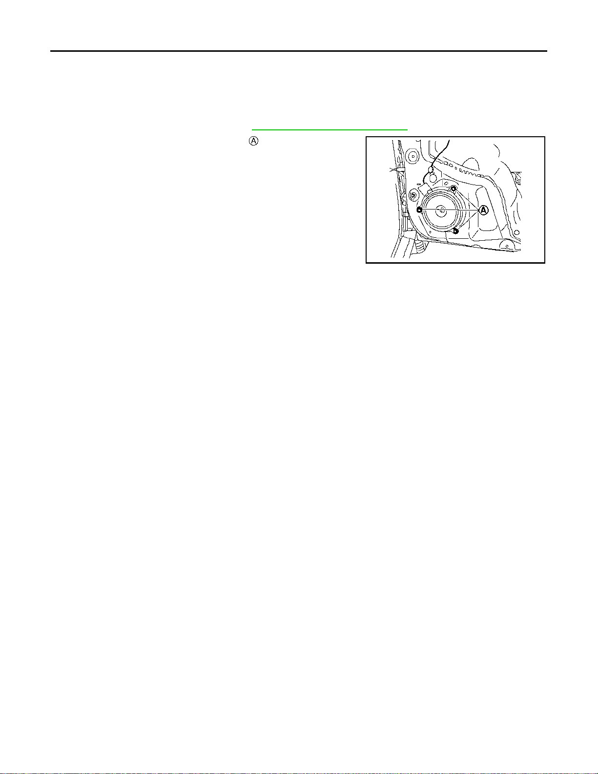
FRONT DOOR SPEAKER
< REMOVAL AND INSTALLATION >
[BASE AUDIO]
FRONT DOOR SPEAKER
Removal and Installation INFOID:0000000011010046
REMOVAL
1. Remove the front door finisher. Refer to INT-14, "Removal and Installation".
2. Remove the front door speaker screws .
3. Disconnect the harness connector from the front door speaker
and remove.
JSNIA6727ZZ
INSTALLATION
Install in the reverse order of removal.
AV-52
Page 58
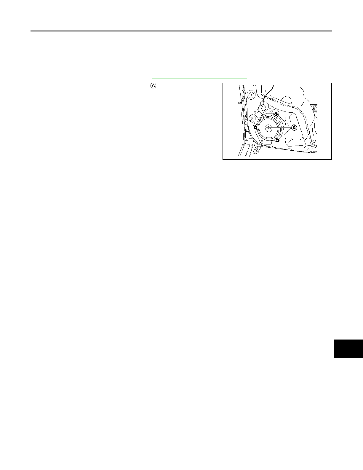
< REMOVAL AND INSTALLATION >
REAR DOOR SPEAKER
[BASE AUDIO]
REAR DOOR SPEAKER
Removal and Installation INFOID:0000000011010047
REMOVAL
1. Remove the rear door finisher. Refer to INT-19, "Removal and Installation".
2. Remove the rear door speaker screws .
3. Disconnect the harness connector from the rear door speaker
and remove.
JSNIA6727ZZ
INSTALLATION
Install in the reverse order of removal.
A
B
C
D
E
F
G
H
AV
I
J
K
L
M
O
P
AV-53
Page 59

FRONT SQUAWKER
< REMOVAL AND INSTALLATION >
[BASE AUDIO]
FRONT SQUAWKER
Removal and Installation INFOID:0000000011066765
REMOVAL
1. Remove the front pillar garnish. Refer to INT-23, "FRONT PILLAR GARNISH : Removal and Installation".
2. Remove the front squawker grille using a suitable tool. Refer to IP-13, "
40, "Exploded View" (RHD models).
3. Pull out the front squawker, disconnect the harness connector from front squawker and remove.
INSTALLATION
Installation is in the reverse order of removal.
Exploded View" (LHD models), IP-
AV-54
Page 60
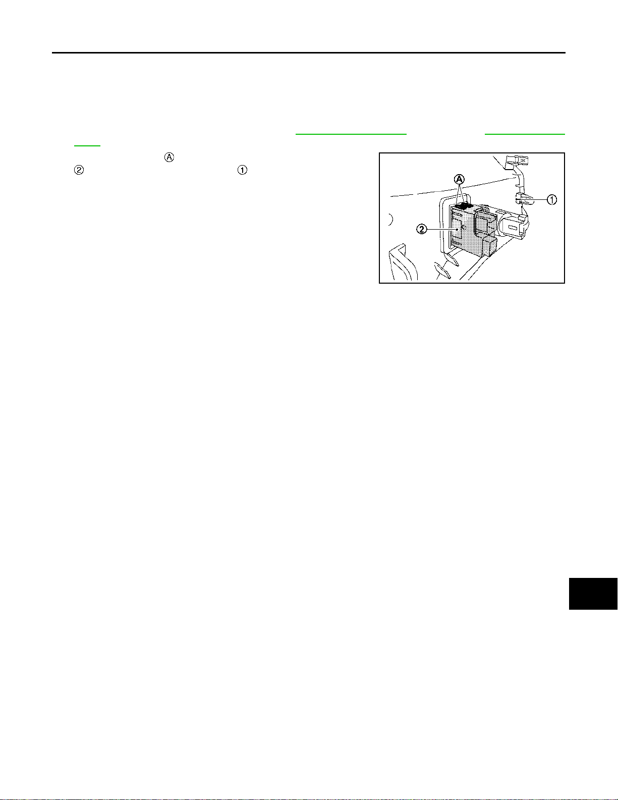
USB CONNECTOR AND AUX JACK
< REMOVAL AND INSTALLATION >
[BASE AUDIO]
USB CONNECTOR AND AUX JACK
Removal and Installation INFOID:0000000011010048
REMOVAL
1. Remove the instrument lower panel. Refer to IP-13, "Exploded View" (LHD models), IP-40, "Exploded
View" (RHD models).
2. Release the pawls and remove the USB connector AUX jack
from the instrument lower panel .
JSNIA6728ZZ
INSTALLATION
Installation is in the reverse order of removal.
A
B
C
D
E
F
G
H
AV
I
J
K
L
M
O
P
AV-55
Page 61
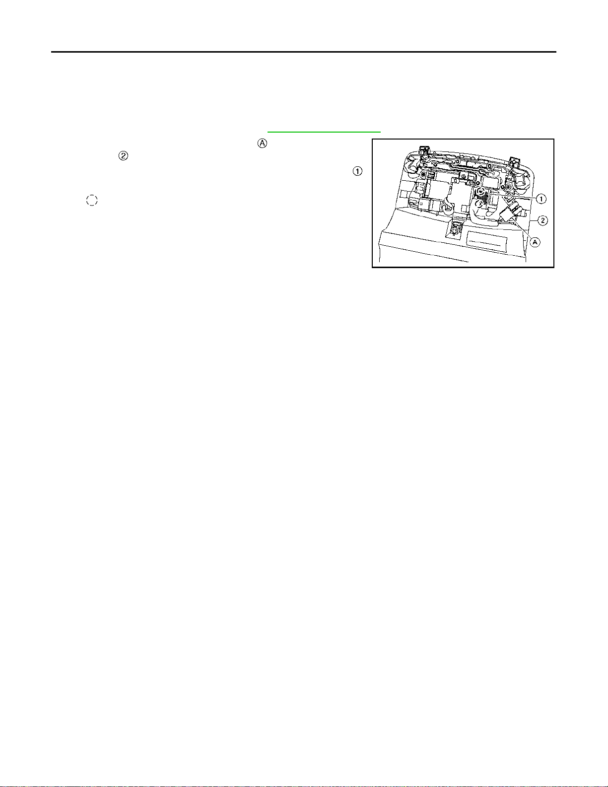
MICROPHONE
< REMOVAL AND INSTALLATION >
[BASE AUDIO]
MICROPHONE
Removal and Installation INFOID:0000000011010049
REMOVAL
1. Remove the map lamp assembly. Refer to INL-76, "Exploded View".
2. Disconnect the microphone connector from the map lamp
assembly .
3. Release the microphone pawls, then remove the microphone .
: Pawl
ALNIA1366ZZ
INSTALLATION
Installation is in the reverse order of removal.
AV-56
Page 62

< REMOVAL AND INSTALLATION >
STEERING SWITCH
[BASE AUDIO]
STEERING SWITCH
Removal and Installation INFOID:0000000011010050
Refer to ST-12, "Exploded View".
NOTE:
Always remove steering switch together with steering wheel.
A
B
C
D
E
F
G
H
AV
I
J
K
L
M
O
P
AV-57
Page 63
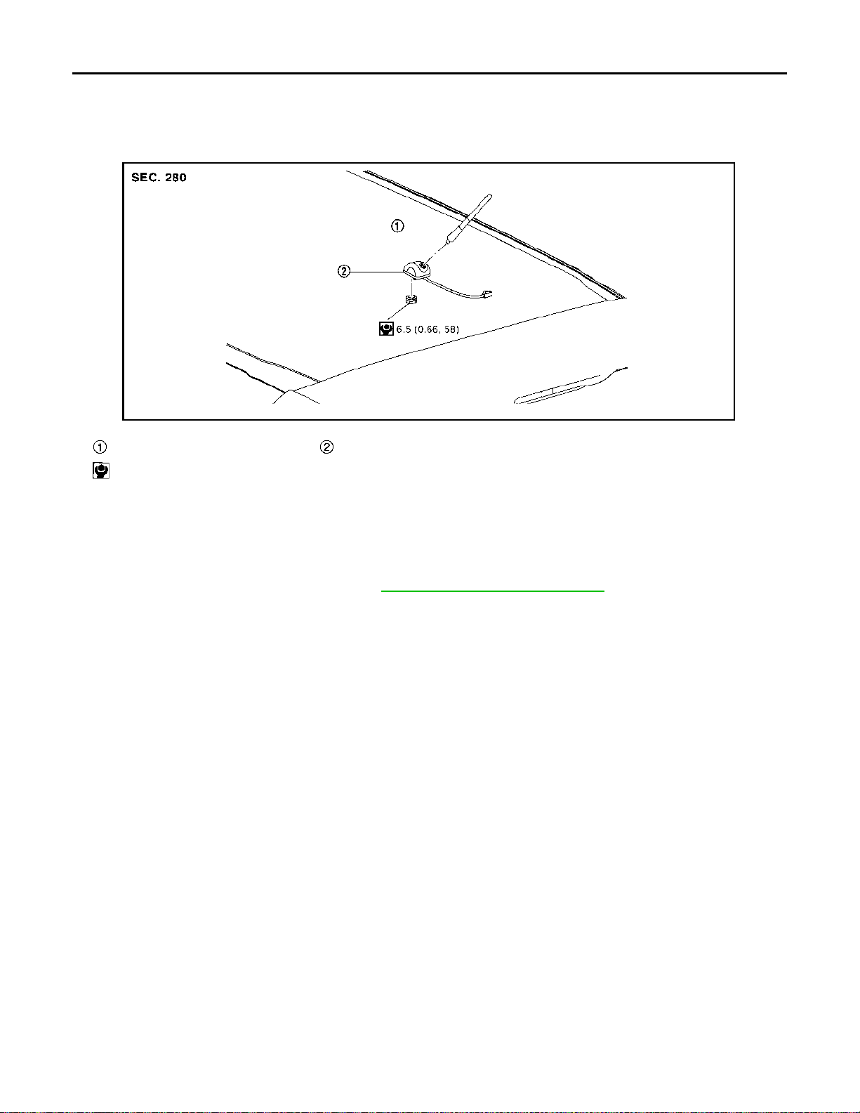
ROOF ANTENNA
< REMOVAL AND INSTALLATION >
[BASE AUDIO]
ROOF ANTENNA
Exploded View INFOID:0000000011010051
JSNIA6913ZZ
Antenna rod Antenna base
: N·m (kg-m, in-lb)
Removal and Installation INFOID:0000000011010052
REMOVAL
1. Remove the antenna rod.
2. Remove the headlining assembly. Refer to INT-37, "
3. Remove the mounting nut to remove the antenna base from the roof panel.
INSTALLATION
Install in the reverse order of removal.
CAUTION:
If the antenna base mounting nut is tightened looser than the specified torque, then this will lower the
sensitivity of the antenna. On the other hand, if the nut is tightened tighter than the specified torque,
then this will deform the roof panel.
Removal and Installation".
AV-58
Page 64
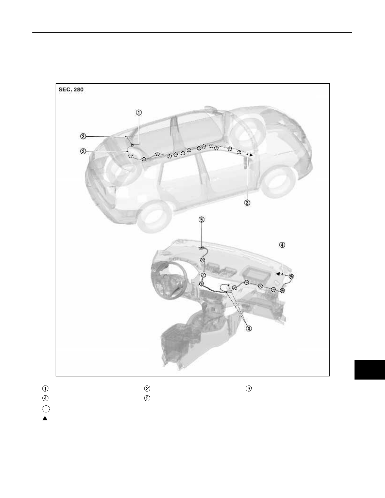
< REMOVAL AND INSTALLATION >
ANTENNA FEEDER
[BASE AUDIO]
ANTENNA FEEDER
Feeder Layout INFOID:0000000010714779
LHD MODELS
A
B
C
D
E
F
G
H
Antenna base Antenna rod With clip connector
Connector
: Clips
: Indicates that the part is connected at points with same symbol in actual vehicle.
*: Not applicable
GPS antenna
I
J
K
L
M
JSNIA7348ZZ
*
AV
O
P
RHD MODELS
AV-59
Page 65
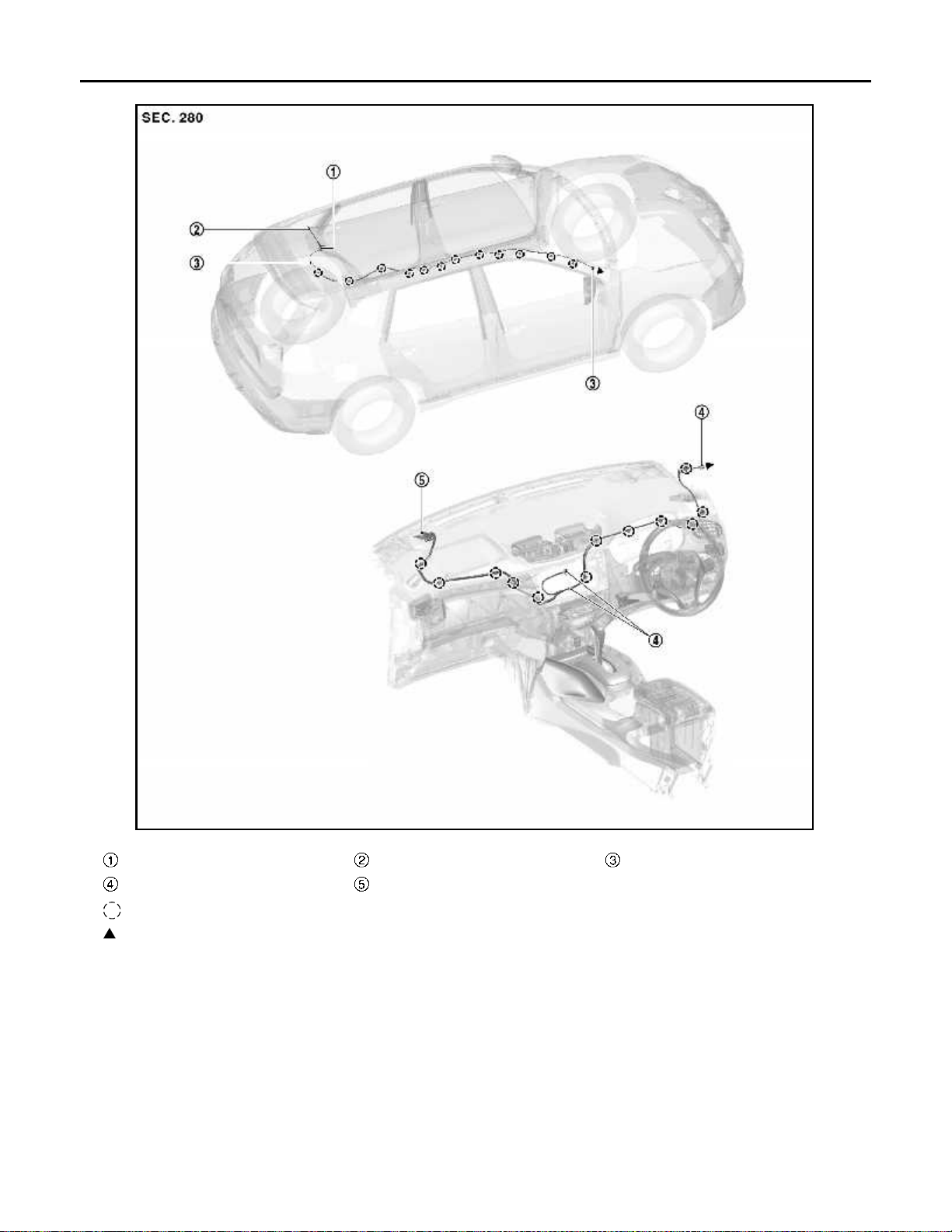
< REMOVAL AND INSTALLATION >
ANTENNA FEEDER
[BASE AUDIO]
Antenna base Antenna rod With clip connector
Connector
: Clips
: Indicates that the part is connected at points with same symbol in actual vehicle.
*: Not applicable
GPS antenna
AV-60
JSNIA7349ZZ
*
Page 66
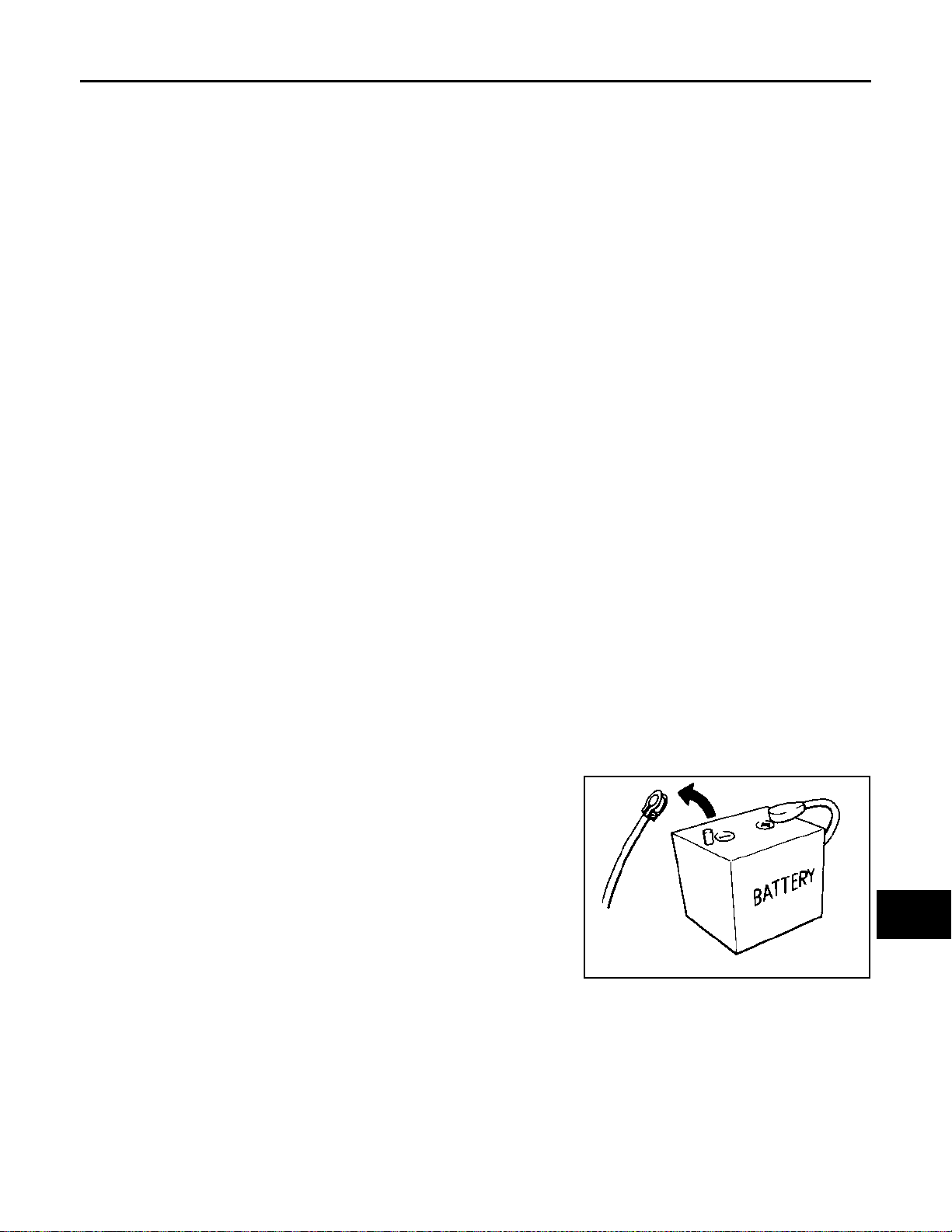
< PRECAUTION >
PRECAUTIONS
[WITH NAVIGATION]
PRECAUTION
PRECAUTIONS
Precaution for Supplemental Restraint System (SRS) "AIR BAG" and "SEAT BELT
PRE-TENSIONER"
The Supplemental Restraint System such as “AIR BAG” and “SEAT BELT PRE-TENSIONER”, used along
with a front seat belt, helps to reduce the risk or severity of injury to the driver and front passenger for certain
types of collision. Information necessary to service the system safely is included in the “SRS AIR BAG” and
“SEAT BELT” of this Service Manual.
WARNING:
Always observe the following items for preventing accidental activation.
• To avoid rendering the SRS inoperative, which could increase the risk of personal injury or death in
the event of a collision that would result in air bag inflation, all maintenance must be performed by
an authorized NISSAN/INFINITI dealer.
• Improper maintenance, including incorrect removal and installation of the SRS, can lead to personal
injury caused by unintentional activation of the system. For removal of Spiral Cable and Air Bag
Module, see “SRS AIR BAG”.
• Never use electrical test equipment on any circuit related to the SRS unless instructed to in this Service Manual. SRS wiring harnesses can be identified by yellow and/or orange harnesses or harness
connectors.
PRECAUTIONS WHEN USING POWER TOOLS (AIR OR ELECTRIC) AND HAMMERS
WARNING:
Always observe the following items for preventing accidental activation.
• When working near the Air Bag Diagnosis Sensor Unit or other Air Bag System sensors with the
ignition ON or engine running, never use air or electric power tools or strike near the sensor(s) with
a hammer. Heavy vibration could activate the sensor(s) and deploy the air bag(s), possibly causing
serious injury.
• When using air or electric power tools or hammers, always switch the ignition OFF, disconnect the
battery, and wait at least 3 minutes before performing any service.
Precautions for Removing Battery Terminal INFOID:0000000011010176
INFOID:0000000010714784
A
B
C
D
E
F
G
H
I
J
• With the adoption of Auto ACC function, ACC power is automatically supplied by operating the intelligent key
or remote keyless entry or by opening/closing the driver side door. In addition, ACC power is supplied even
after the ignition switch is turned to the OFF position, i.e. ACC power is supplied for a certain fixed time.
• When disconnecting the 12V battery terminal, turn off the ACC
power before disconnecting the 12V battery terminal, observing
“How to disconnect 12V battery terminal” described below.
NOTE:
Some ECUs operate for a certain fixed time even after ignition
switch is turned OFF and ignition power supply is stopped. If the
battery terminal is disconnected before ECU stops, accidental DTC
detection or ECU data damage may occur.
• For vehicles with the 2-batteries, be sure to connect the main battery and the sub battery before turning ON the ignition switch.
NOTE:
If the ignition switch is turned ON with any one of the terminals of
main battery and sub battery disconnected, then DTC may be detected.
• After installing the 12V battery, always check "Self Diagnosis Result" of all ECUs and erase DTC.
NOTE:
The removal of 12V battery may cause a DTC detection error.
SEF289H
HOW TO DISCONNECT 12V BATTERY TERMINAL
Disconnect 12V battery terminal according to Instruction 1 or Instruction 2 described below.
For vehicles parked by ignition switch OFF, refer to Instruction 2.
INSTRUCTION 1
1. Open the hood.
K
L
M
AV
O
P
AV-61
Page 67
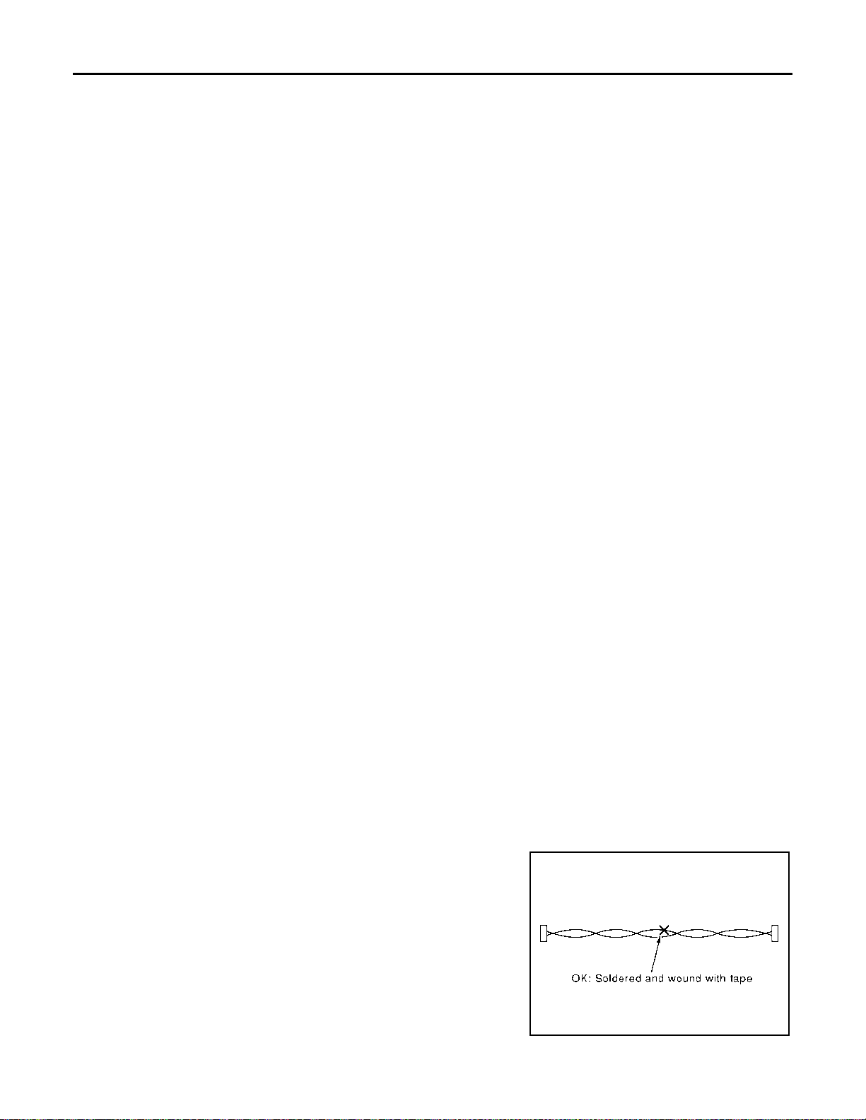
PRECAUTIONS
< PRECAUTION >
2. Turn key switch to the OFF position with the driver side door opened.
3. Get out of the vehicle and close the driver side door.
4. Wait at least 3 minutes. For vehicle with the engine listed below, remove the battery terminal after a lapse
of the specified time.
D4D engine : 20 minutes
HRA2DDT : 12 minutes
K9K engine : 4 minutes
M9R engine : 4 minutes
R9M engine : 4 minutes
V9X engine : 4 minutes
CAUTION:
While waiting, never operate the vehicle such as locking, opening, and closing doors. Violation of
this caution results in the activation of ACC power supply according to the Auto ACC function.
5. Remove 12V battery terminal.
CAUTION:
After installing 12V battery, always check self-diagnosis results of all ECUs and erase DTC.
INSTRUCTION 2 (FOR VEHICLES PARKED BY IGNITION SWITCH OFF)
1. Unlock the door with intelligent key or remote keyless entry.
NOTE:
At this moment, ACC power is supplied.
2. Open the driver side door.
3. Open the hood.
4. Close the driver side door.
5. Wait at least 3 minutes.
CAUTION:
While waiting, never operate the vehicle such as locking, opening, and closing doors. Violation of
this caution results in the activation of ACC power supply according to the Auto ACC function.
6. Remove 12V battery terminal.
CAUTION:
After installing 12V battery, always check self-diagnosis results of all ECUs and erase DTC.
[WITH NAVIGATION]
Precaution for Trouble Diagnosis INFOID:0000000010714786
AV COMMUNICATION SYSTEM
• Do not apply voltage of 7.0 V or higher to the measurement terminals.
• Use the tester with its open terminal voltage being 7.0 V or less.
• Be sure to turn ignition switch OFF and disconnect the battery cable from the negative terminal before
checking the circuit.
Precaution for Harness Repair INFOID:0000000010714787
AV COMMUNICATION SYSTEM
• Solder the repaired parts, and wrap with t ape. [Frays of twisted line
must be within 110 mm (4.33 in).]
PKIA0306E
AV-62
Page 68
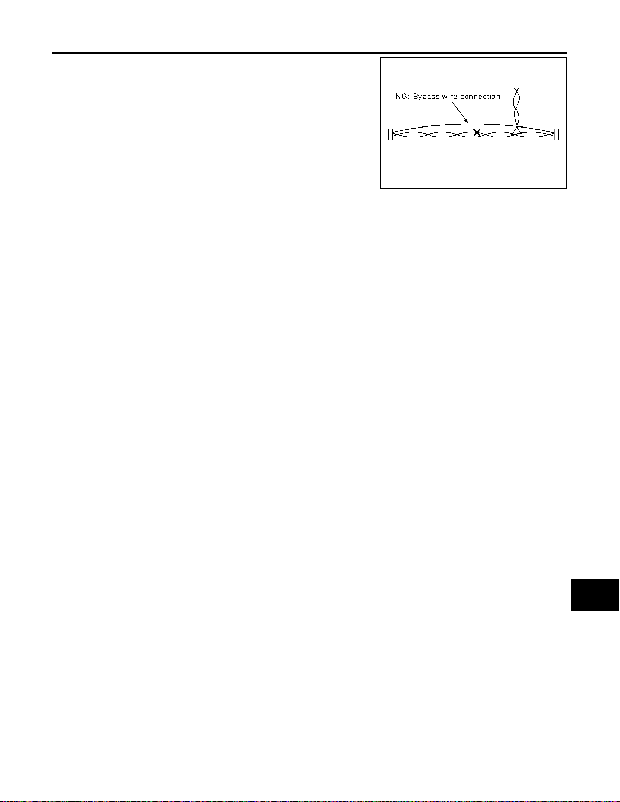
PRECAUTIONS
< PRECAUTION >
• Do not perform bypass wire connections for the repair parts. (The
spliced wire will become separated and the characteristics of
twisted line will be lost.)
[WITH NAVIGATION]
A
B
C
PKIA0307E
D
E
F
G
AV
H
I
J
K
L
M
O
AV-63
P
Page 69
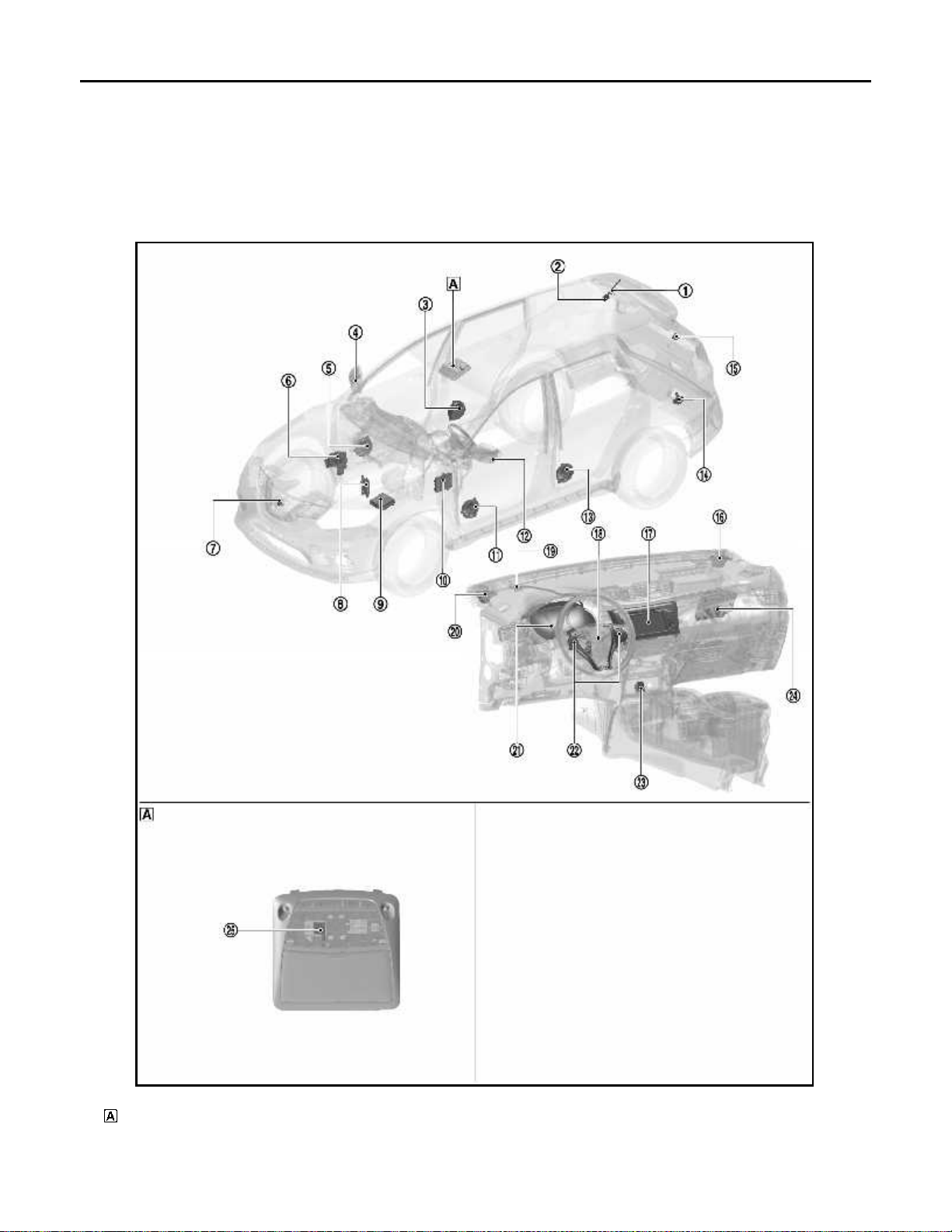
COMPONENT PARTS
< SYSTEM DESCRIPTION >
[WITH NAVIGATION]
SYSTEM DESCRIPTION
COMPONENT PARTS
Component Parts Location INFOID:0000000010714788
LHD MODELS
Map lamp
JSNIA7355ZZ
AV-64
Page 70
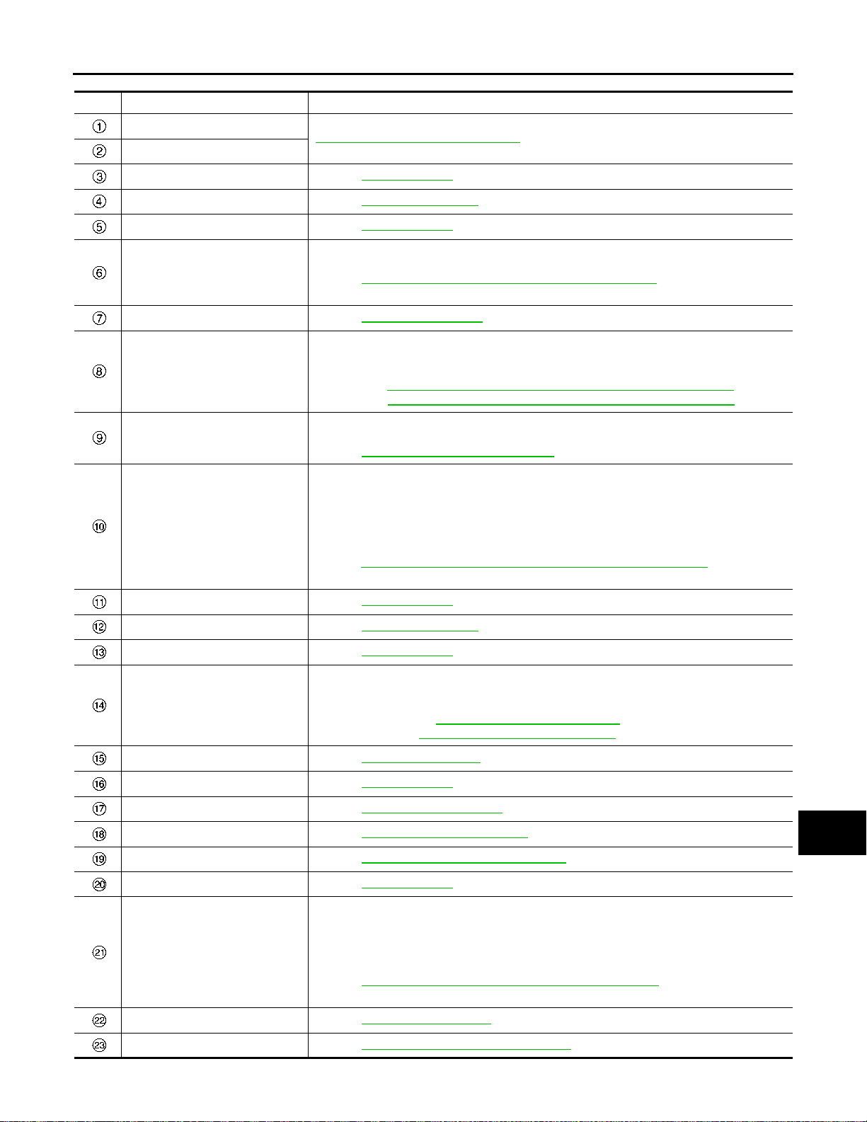
< SYSTEM DESCRIPTION >
COMPONENT PARTS
[WITH NAVIGATION]
No. Component Function
Antenna rod
Antenna base
Rear door speaker RH Refer to AV-69, "
Side camera RH Refer to AV-77, "
Front door speaker RH Refer to AV-69, "
ABS actuator and electric unit
(control unit)
Front camera Refer to AV-76, "
TCM (CVT models)
IPDM E/R (M/T models)
BCM
Front door speaker LH Refer to AV-69, "
Side camera LH Refer to AV-77, "
AV-71, "
Antenna and Antenna Feeder"
Speaker".
Side Camera".
Speaker".
Transmits the vehicle speed signal to the around view monitor control unit via CAN communication.
Refer to BRC-25, "
location.
Transmit s the shi ft positio n signal to the around v iew monit or contro l unit v ia CAN com munication.
Refer to the following for detailed installation location.
•RE0F10D: TM-235, "
•RE0F10G: TM-466, "CVT CONTROL SYSTEM : Component Parts Location"
Transmits the gear position signal to the around view monitor control unit via CAN commu-
nication.
Refer to PCS-5, "
• Transmits the door switch signal to the around view monitor control unit via CAN communication.
• Transmits the following signals to the NAVI control unit.
- Reverse signal
- Dimmer signal
- Auto acc input signal
Refer to BCS-6, "
stallation location.
ABS Actuator and Electric Unit (Control Unit)", for detailed installation
Front Camera".
CVT CONTROL SYSTEM : Component Parts Location"
Component Parts Location", for detailed installation location.
BODY CONTROL SYSTEM : Component Parts Location", for detailed in-
Speaker".
Side Camera".
A
B
C
D
E
F
G
H
I
J
Rear door speaker LH Refer to AV-69, "
Transmits the sonar indicator signal to the around view monitor control unit via CAN communication.
Sonar control unit
Rear camera Refer to AV-77, "Rear Camera".
Front squawker RH Refer to AV-69, "
NAVI control unit Refer to AV-68, "
Steering angle sensor Refer to AV-76, "
GPS antenna Refer to AV-71, "
Front squawker LH Refer to AV-69, "
Combination meter
Steering switch Refer to AV-71, "
USB connector and AUX jack Refer to AV-76, "
Refer to following for detailed installation location.
• Without park assist: SN-8, "
• With park assist: SN-119, "Component Parts Location"
• Transmits the steering switch signal to the NAVI control unit via AV communication.
• Transmits the vehicle speed signal to the NAVI control unit.
• Receives the meter display signal from the NAVI control unit via AV communication.
• Receives the buzzer output signal from the around view monitor control unit via CAN
communication.
Refer to MWI-7, "
location.
Speaker".
Speaker".
NAVI Control Unit".
Steering Angle Sensor".
Antenna and Antenna Feeder".
Speaker".
METER SYSTEM : Component Parts Location", for detailed installation
Steering Switch".
USB Connector and AUX Jack".
Component Parts Location"
K
L
M
AV
O
P
AV-65
Page 71
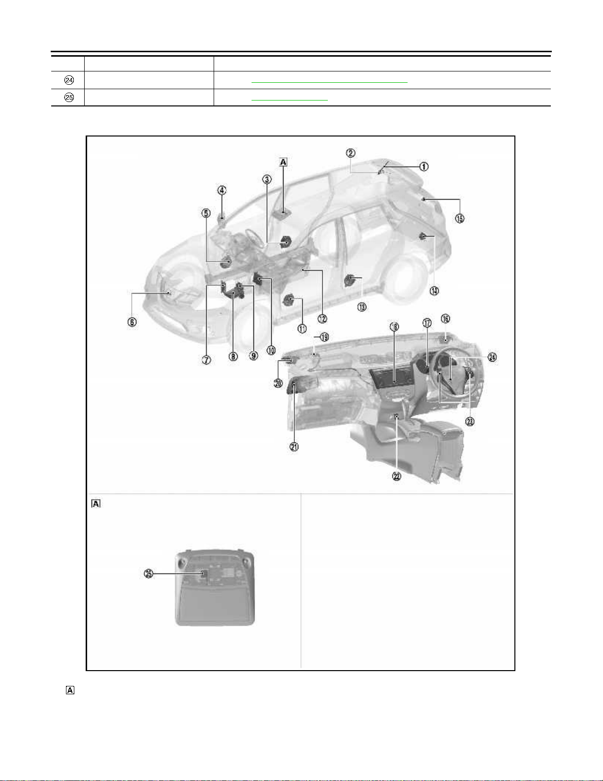
COMPONENT PARTS
< SYSTEM DESCRIPTION >
No. Component Function
Around view monitor control unit Refer to AV-76, "Around View Monitor Control Unit".
[WITH NAVIGATION]
Microphone Refer to AV-70, "
RHD MODELS
Microphone".
Map lamp
JSNIA7356ZZ
AV-66
Page 72
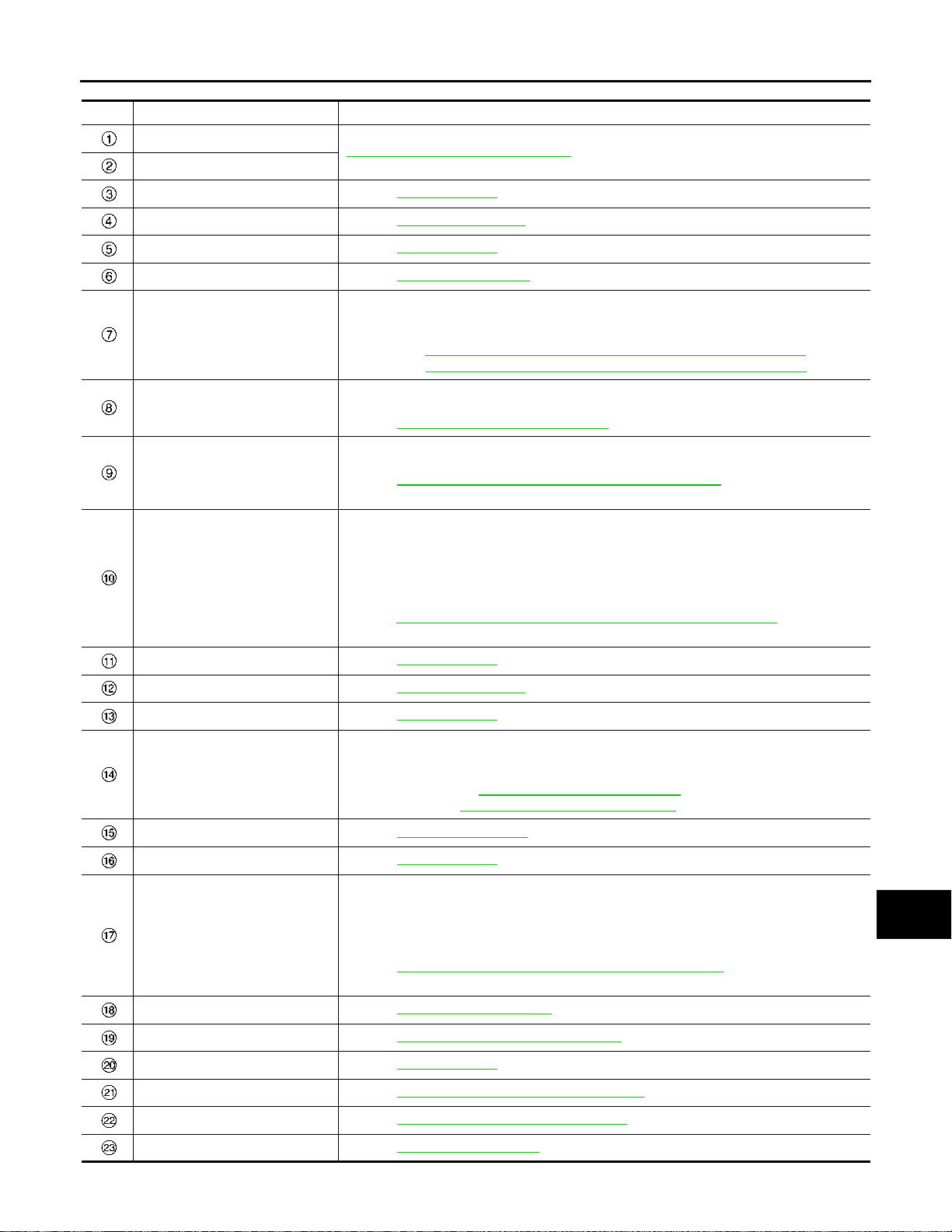
< SYSTEM DESCRIPTION >
COMPONENT PARTS
[WITH NAVIGATION]
No. Component Function
Antenna rod
Antenna base
Rear door speaker RH Refer to AV-69, "
Side camera RH Refer to AV-77, "
Front door speaker RH Refer to AV-69, "
Front camera Refer to AV-76, "
TCM (CVT models)
IPDM E/R (M/T models)
ABS actuator and electric unit
(control unit)
BCM
Front door speaker LH Refer to AV-69, "
Side camera LH Refer to AV-77, "
AV-71, "
Antenna and Antenna Feeder"
Speaker".
Side Camera".
Speaker".
Front Camera".
Transmit s the shi ft positio n signal to the around v iew monit or contro l unit v ia CAN com munication.
Refer to the following for detailed installation location.
•RE0F10D: TM-235, "
•RE0F10G: TM-466, "CVT CONTROL SYSTEM : Component Parts Location"
Transmits the gear position signal to the around view monitor control unit via CAN communication.
Refer to PCS-5, "
Transmits the vehicle speed signal to the around view monitor control unit via CAN communication.
Refer to BRC-25, "
location.
• Transmits the door switch signal to the around view monitor control unit via CAN communication.
• Transmits the following signals to the NAVI control unit.
- Reverse signal
- Dimmer signal
- Auto acc input signal
Refer to BCS-6, "
stallation location.
CVT CONTROL SYSTEM : Component Parts Location"
Component Parts Location", for detailed installation location.
ABS Actuator and Electric Unit (Control Unit)", for detailed installation
BODY CONTROL SYSTEM : Component Parts Location", for detailed in-
Speaker".
Side Camera".
A
B
C
D
E
F
G
H
I
J
Rear door speaker LH Refer to AV-69, "
Transmits the sonar indicator signal to the NAVI control unit and the around view monitor
control unit via CAN communication .
Sonar control unit
Rear camera Refer to AV-77, "Rear Camera".
Front squawker RH Refer to AV-69, "
Combination meter
NAVI control unit Refer to AV-68, "
GPS antenna Refer to AV-71, "
Front squawker LH Refer to AV-69, "
Around view monitor control unit Refer to AV-76, "
USB connector and AUX jack Refer to AV-76, "
Steering switch Refer to AV-71, "
Refer to following for detailed installation location.
• Without park assist: SN-8, "
• With park assist: SN-119, "Component Parts Location"
• Transmits the steering switch signal to the NAVI control unit via AV communication.
• Transmits the vehicle speed signal to the NAVI control unit.
• Receives the meter display signal from the NAVI control unit via AV communication.
• Receives the buzzer output signal from the around view monitor control unit via CAN
communication.
Refer to MWI-7, "
location.
Speaker".
Speaker".
METER SYSTEM : Component Parts Location", for detailed installation
NAVI Control Unit".
Antenna and Antenna Feeder".
Speaker".
Around View Monitor Control Unit".
USB Connector and AUX Jack".
Steering Switch".
Component Parts Location"
K
L
M
AV
O
P
AV-67
Page 73
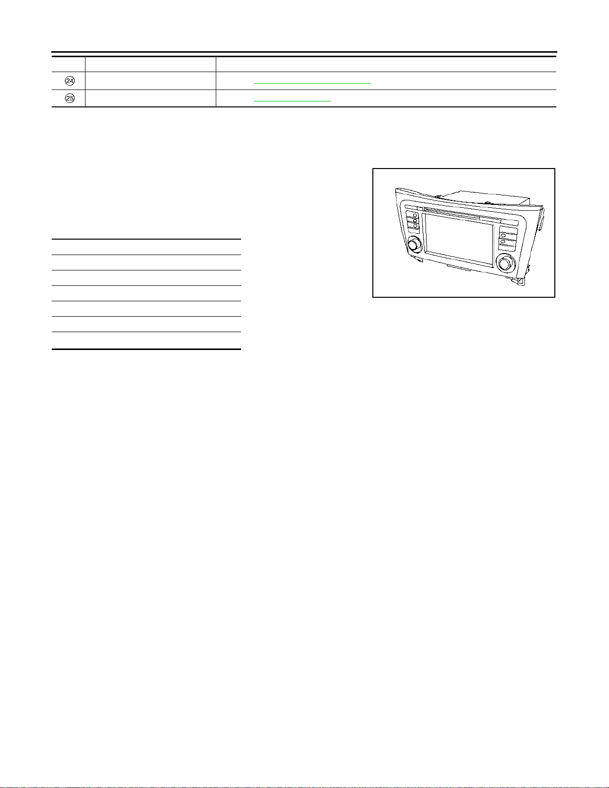
COMPONENT PARTS
< SYSTEM DESCRIPTION >
No. Component Function
Steering angle sensor Refer to AV-76, "Steering Angle Sensor".
[WITH NAVIGATION]
Microphone Refer to AV-70, "
NAVI Control Unit
Microphone".
INFOID:0000000010714789
The audio system is equipped with following function.
DESCRIPTION
• 7 inch display integrated NAVI control unit is installed at the center
of the instrument panel.
• The NAVI control unit is equipped with the following parts. It is the
master unit integrated with functions and controls the multi-AV system.
Units equipped
SD card slot
7-inch monitor
Audio amplifier
AM/FM electronic tuner
CD drive
®
Bluetooth
module
• A possible route line is generated on the camera image from the rear view camera, and it is shown on the
display.
• It has the built-in gyro sensor and acceleration sensor as a vehicle position calculation sensor. Map data is
read from an SD card in the SD slot.
-SD card
• It records the map data, guide information, etc.
- Gyroscope
• Detects vehicle cornering condition.
- Acceleration sensor
• Detects the inclination angle and height variation of the vehicle.
ALNIA1590ZZ
Display
• Touch panel function is adopted to improve operability.
• Composite image signals (around view camera image) are displayed.
Audio Amplifier
• 40 W x 4ch amplifiers are installed.
• Audio sound, TEL voice and guiding voice are output to each speaker.
AM/FM Electronic Tuner
• The AM/FM electric tuner includes the PLL frequency synthesizer system.
CD Drive
• It is CD-R/CD-RW compliant and enables MP3 and WMA files to play music.
• It displays the artist name, album title or song title recorded to the file by the ID3 tag/WMA tag display function.
Bluetooth® Module
• Wireless connection to the audio device equipped with Bluetooth® communication can play music.
• Five units of Bluetooth
®
communication devices including audio devices and cellular phones can be regis-
tered to the NAVI control unit.
Specification
AV-68
Page 74

< SYSTEM DESCRIPTION >
COMPONENT PARTS
[WITH NAVIGATION]
Screen size
Display
Amplifier output 40 W × 4 ch
CD drive
USB
®
Bluetooth
Hands-free phone
Camera controller Guideline display function Width/distance display
Other functions
audio
Number of pixels 480 × 272 pixels
Drive type TFT active matrix method
Touch panel detection Analog resistive touch
Used disc φ12 cm
Playable disc CD
Playable format Music
Text display function ID3 / WMA tag
High communication standard USB2.0
Playable format Music
Text display function ID3 / WMA tag
iPod Classic 5th generation and later
iPod Action
Compliant communication
type
Compliant profile
Compliant communication
type
Compliant profile HFP v10r00
*2
Wireless connection
Wireless connection
iPod nano 1st generation and later
iPod touch 1st generation and later
Bluetooth
Bluetooth
Speed sensitive volume function
Steering switch compliant
7-inch
(15.5 cm × 8.72 mm)
CD-ROM (CD-DA)
*1
CD-R
*1
CD-RW
MP3
WMA
Artist name
Album title
Song title
MP3
WMA
Artist name
Album title
Song title
iPhone 3G and later
®
communication
A2DP 1.2
AVRCP 1.4
®
communication compliant
type
*1: If the reflectance of the surface of the media is low, the data may not be read.
*2: It may not be used if it is not updated to the latest firmware or partial functions may not work if it is used.
Speaker INFOID:0000000010714790
A
B
C
D
E
F
G
H
I
J
K
L
M
AV
O
FRONT DOOR SPEAKER
P
AV-69
Page 75
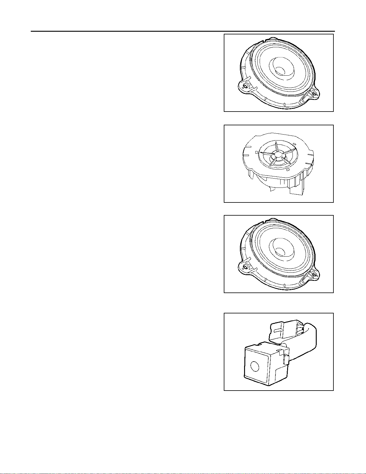
COMPONENT PARTS
< SYSTEM DESCRIPTION >
• φ16.0 cm speaker is installed to the bottom of the front door.
• Sound signal is input from the NAVI control unit to output high, mid
and low range sound.
Maximum input : 40 W
Rated input : 20 W
Impedance : 4 Ω
FRONT SQUAWKER
• φ8.0 cm squawker for high-range sounds is installed in the instrument panel assembly.
• Sound signal is input from the NAVI control unit to output high
range sounds.
[WITH NAVIGATION]
JSNIA5958ZZ
ALNIA1593ZZ
REAR DOOR SPEAKER
• φ16.0 cm speaker is installed to the bottom of the rear door.
• Sound signal is input from the NAVI control unit to output high, mid
and low range sound.
Maximum input : 40 W
Rated input : 20 W
Impedance : 4 Ω
JSNIA5958ZZ
Microphone INFOID:0000000010714791
• The microphone is installed on the map lamp assembly.
• The power is supplied from the NAVI control unit to the microphone, transmitting sound signals to the NAVI control unit at the
during hands-free phone communication.
AV-70
JPNIA1448ZZ
Page 76
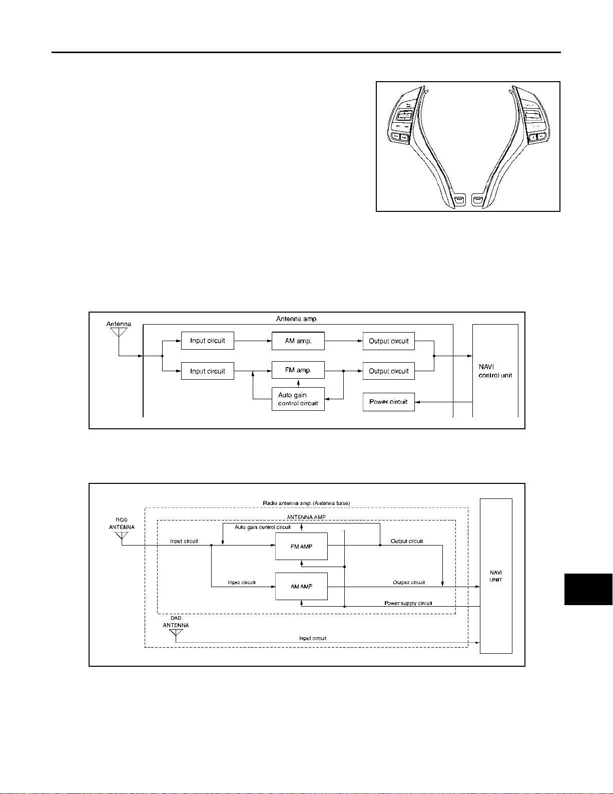
COMPONENT PARTS
< SYSTEM DESCRIPTION >
[WITH NAVIGATION]
Steering Switch INFOID:0000000010714792
• Hands-free phone, navigation, and audio operations can be performed.
• This switch is connected to combination meter, and switch operation signal is transmitted to combination meter.
• Combination meter transmits steering switch signal to NAVI control
unit via AV communication.
JSNIA7234ZZ
A
B
C
D
Antenna and Antenna Feeder INFOID:0000000010714793
ANTENNA AMP. AND RADIO ANTENNA
Without DAB antenna
• AM/FM radio rod antenna and antenna base are located on the rear of the roof.
• The antenna amp. is built into the antenna base.
• The AM/FM radio main antenna path has an antenna amp. to obtain sufficient reception power.
JSNIA5180GB
With DAB antenna
• AM/FM radio rod antenna, antenna base and DAB antenna are located on the rear of the roof.
• The antenna amp. and DAB antenna are built into the antenna base.
• The AM/FM radio main antenna path has an antenna amp. to obtain sufficient reception power.
E
F
G
H
I
J
K
L
GPS ANTENNA
M
AV
O
JSNIA7241GB
P
AV-71
Page 77
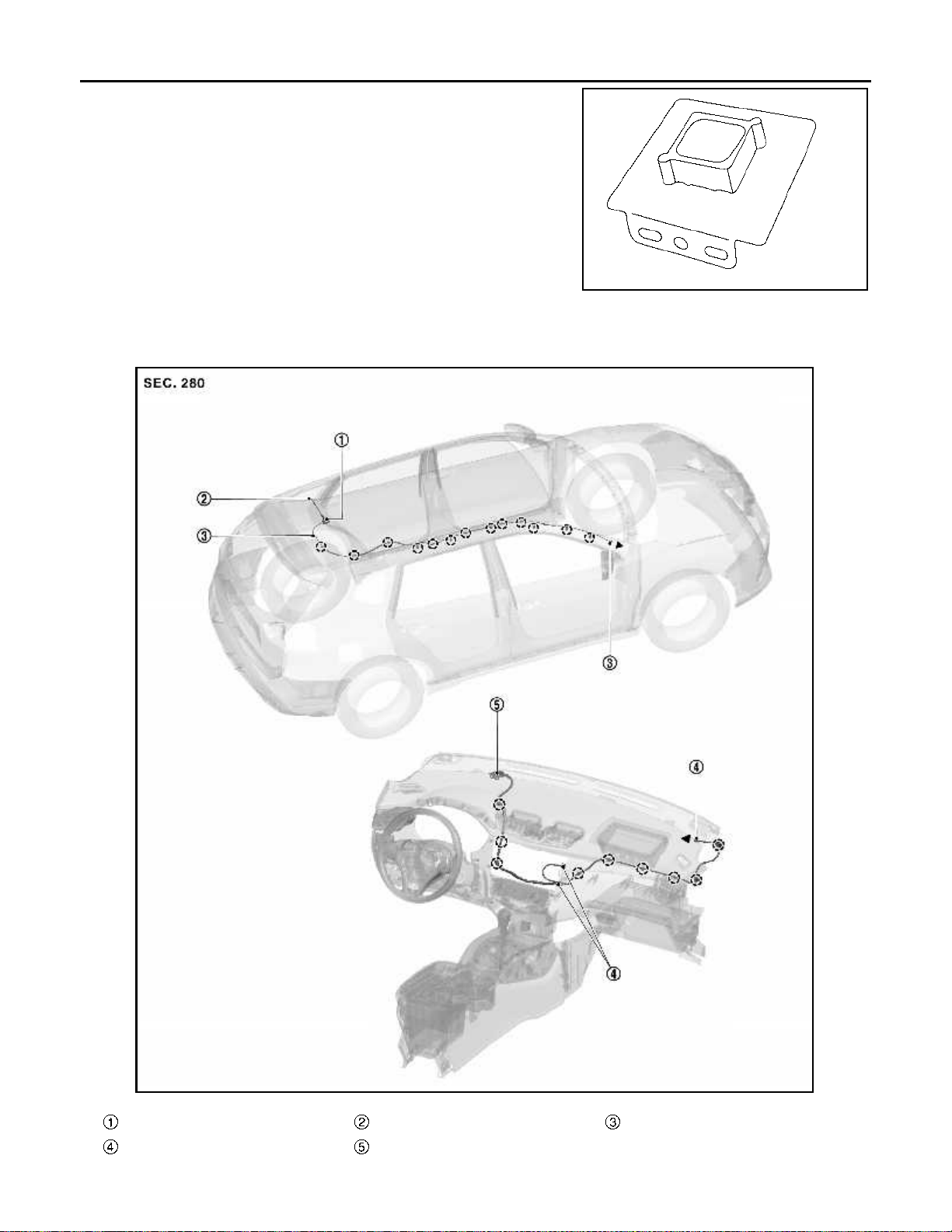
COMPONENT PARTS
< SYSTEM DESCRIPTION >
• GPS antenna is installed in the instrument panel.
• Power is supplied from the NAVI control unit.
• This antenna amplifies radio waves received from the GPS satellite and transmits the GPS signal to the NAVI control unit.
NOTE:
An object on the instrument panel may cause the reception sensitivity to be decreased.
ANTENNA FEEDER LAYOUT
LHD Models Without DAB antenna
[WITH NAVIGATION]
JSNIA5132ZZ
Antenna base Antenna rod With clip connector
Connector GPS antenna
AV-72
JSNIA7348ZZ
Page 78
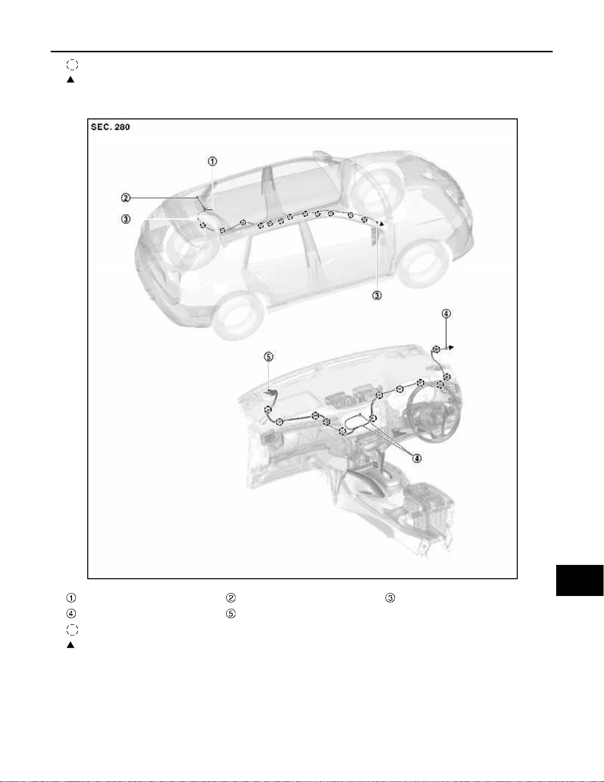
< SYSTEM DESCRIPTION >
COMPONENT PARTS
[WITH NAVIGATION]
: Clips
: Indicates that the part is connected at points with same symbol in actual vehicle.
RHD Models without DAB antenna
A
B
C
D
E
F
G
H
Antenna base Antenna rod With clip connector
Connector GPS antenna
: Clips
: Indicates that the part is connected at points with same symbol in actual vehicle.
LHD Models With DAB antenna
JSNIA7349ZZ
I
J
K
L
M
AV
O
P
AV-73
Page 79
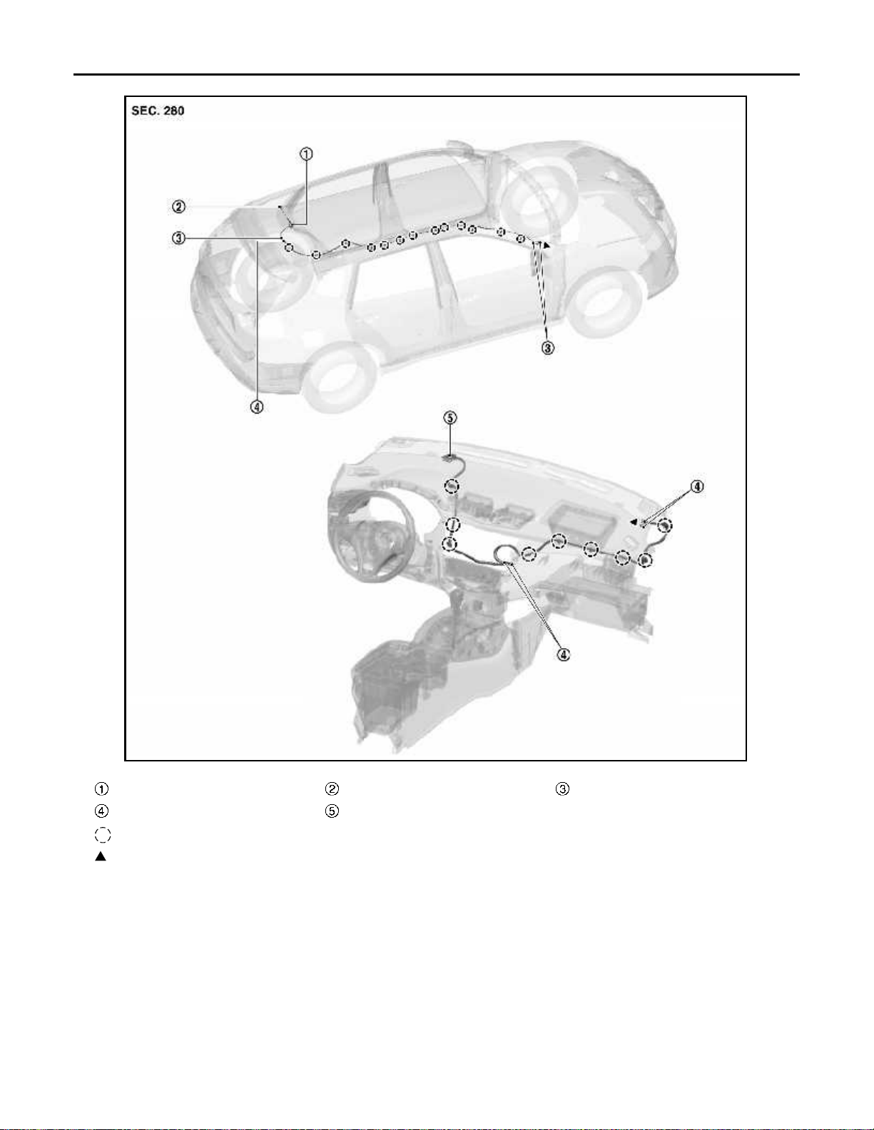
< SYSTEM DESCRIPTION >
COMPONENT PARTS
[WITH NAVIGATION]
Antenna base Antenna rod With clip connector
Connector GPS antenna
: Clips
: Indicates that the part is connected at points with same symbol in actual vehicle.
RHD Models with DAB antenna
JSNIA7358ZZ
AV-74
Page 80
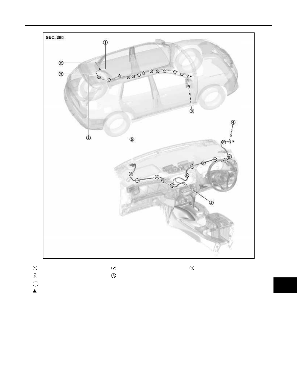
< SYSTEM DESCRIPTION >
COMPONENT PARTS
[WITH NAVIGATION]
A
B
C
D
E
F
G
Antenna base Antenna rod With clip connector
Connector GPS antenna
: Clips
: Indicates that the part is connected at points with same symbol in actual vehicle.
H
I
J
K
L
JSNIA7359ZZ
M
AV
O
AV-75
P
Page 81
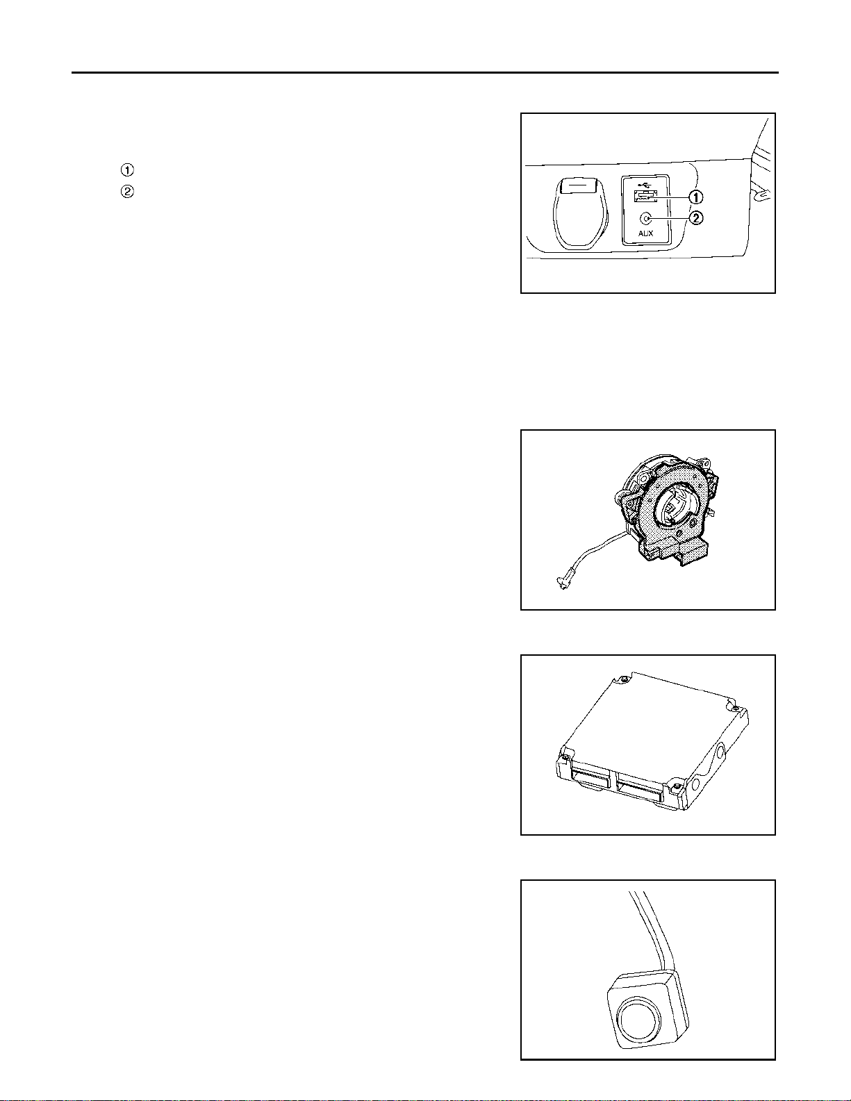
< SYSTEM DESCRIPTION >
COMPONENT PARTS
[WITH NAVIGATION]
USB Connector and AUX Jack
INFOID:0000000010714794
• USB connector and AUX jack is installed on the instrument lower
panel center.
USB connector
AUX jack
• iPod and USB memory can be connected to the NAVI control unit.
• Connection to an external audio device can provide sound output.
External input terminal for connection φ3.5 mm stereo mini-jack
NOTE:
JSNIA6736ZZ
When connected to monaural mini-jack plug cable, sound may not
be output.
SD Card INFOID:0000000010714795
Map data is sent to the NAVI control unit from the SD slot.
St eering Angle Sensor INFOID:0000000010714796
• Steering angle sensor is installed to the spiral cable.
• Steering angle sends the steering signal necessary for predictive
course line of the rear view monitor to the NAVI control unit via
CAN communication. (Models without around view monitor)
• Steering angle sends the steering signal necessary for predictive
course line of the rear view monitor to the around view monitor
control unit via CAN communication. (Models with around view
monitor)
JSNIA1571ZZ
Around View Monitor Control Unit INFOID:0000000010714797
• The around view monitor control unit is installed at the end of the
glove box assembly.
• Necessary signals are transmitted/received to/from control unit via
CAN communication.
• Camera image signals received from each camera are converted/
synthesized in the around view monitor control unit and transmitted
to the NAVI control unit.
• Vehicle width guide lines, predicted course line, vehicle front guiding line and vehicle side line, and vehicle icon are rendered with
the around view monitor control unit and combined with camera
image.
JSOIA0646ZZ
Front Camera INFOID:0000000010714798
• The front camera is installed to the front grille.
• Super-small CMOS camera (color) using CMOS
pickup element is adopted.
• Power for the camera is supplied from the around view monitor
control unit, and the image at the front of the vehicle is sent to the
around view monitor control unit.
NOTE:
*: “CMOS” is abbreviation of Complementary Metal Oxide Semiconductor, and features low power consumption and high speed reading
rate of electric charge.
*
for the image
JSNIA5851ZZ
AV-76
Page 82
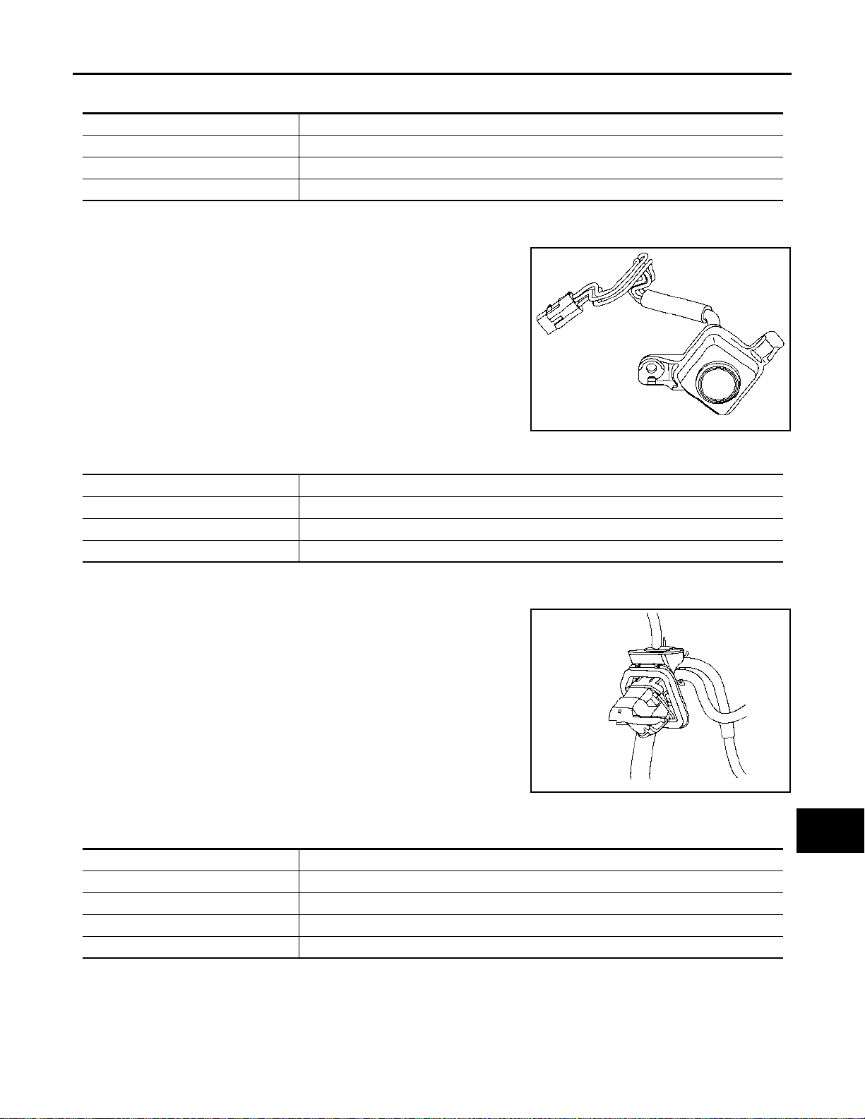
COMPONENT PARTS
< SYSTEM DESCRIPTION >
Specification
Image pickup element 1/4-inch CMOS image sensor
Effective number of pixels Approx. 300,000 pixels (632 × 480)
Minimum brightness 1 lx
Angle of view H: 190.4° V: 141.8°
[WITH NAVIGATION]
A
B
Side Camera INFOID:0000000010714799
• The side camera is installed to the door mirror .
• Super-small CMOS camera (color) using CMOS
*
for the image
pickup element is adopted.
• Power for the camera is supplied from the around view monitor
control unit, and the image at the side of the vehicle is sent to the
around view monitor control unit.
NOTE:
*: “CMOS” is abbreviation of Complementary Metal Oxide Semiconductor, and features low power consumption and hi gh speed reading
rate of electric charge.
JSNIA5852ZZ
Specification
Image pickup element 1/4-inch CMOS image sensor
Effective number of pixels Approx. 300,000 pixels (632 × 480)
Minimum brightness 1 lx
Angle of view H: 190.4° V: 141.8°
Rear Camera INFOID:0000000010714800
• The rear camera is installed to the back door finisher.
• Super-small CMOS camera (color) using CMOS
pickup element is adopted.
• With the mirror processing function, a mirror image is sent as if it is
viewed by a rear view mirror.
• Power for the camera is supplied from the around view monitor
control unit, and the image at the rear of the vehicle is sent to the
around view monitor control unit.
NOTE:
*: “CMOS” is abbreviation of Complementary Metal Oxide Semiconductor, and features low power consumption and hi gh speed reading
rate of electric charge.
*
for the image
JSNIA5853ZZ
C
D
E
F
G
H
I
J
K
L
M
Specification
Image pickup element 1/4-inch CMOS image sensor
Effective number of pixels Approx. 300,000 pixels (632 × 480)
Minimum brightness 1 lx
Angle of view H: 190.4° V: 141.8°
Image With mirror processing function
AV-77
AV
O
P
Page 83
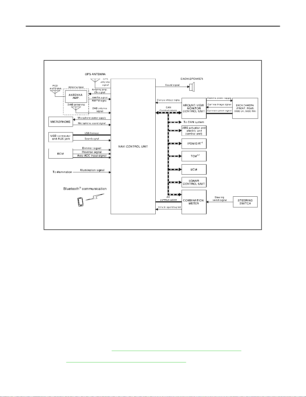
SYSTEM
< SYSTEM DESCRIPTION >
[WITH NAVIGATION]
SYSTEM
System Description INFOID:0000000010714801
SYSTEM DIAGRAM
JSNIA7281GB
*1: With M/T models
*2: With CVT models
DESCRIPTION
Refer to Owner’s Manual for navigation and audio system operating instructions.
Audio function and display are built into NAVI control unit.
This navigation has the following functions.
• Map data on SD card.
• Full support for playback of music from iPod
*: iPod is a trademark of Apple inc., registered in the U.S. and other countries.
• High resolution full color touch panel 7 inch “QVGA” display.
• FM/AM digital tuner.
• DAB radio.
• USB interface.
• AUX in jack
• Bluetooth
• Hands-free phone system.
NOTE:
• The auto ACC function allows the operation of audio and navigation without operating the ignition switch. In
addition, even after the ignition switch is turned OFF, audio and navigation can be operated for 10 minutes.
For the auto ACC function, refer to PCS-68, "
• The settings of the auto ACC function can be changed with the CONSULT (work support of BCM). For
details, refer to BCS-47, "
®
audio streaming.
BCM : CONSULT Function (BCM - BCM)".
*
, iPhone, and USB device.
AUTO ACC FUNCTION : System Description".
NAVIGATION SYSTEM FUNCTION
Description
AV-78
Page 84
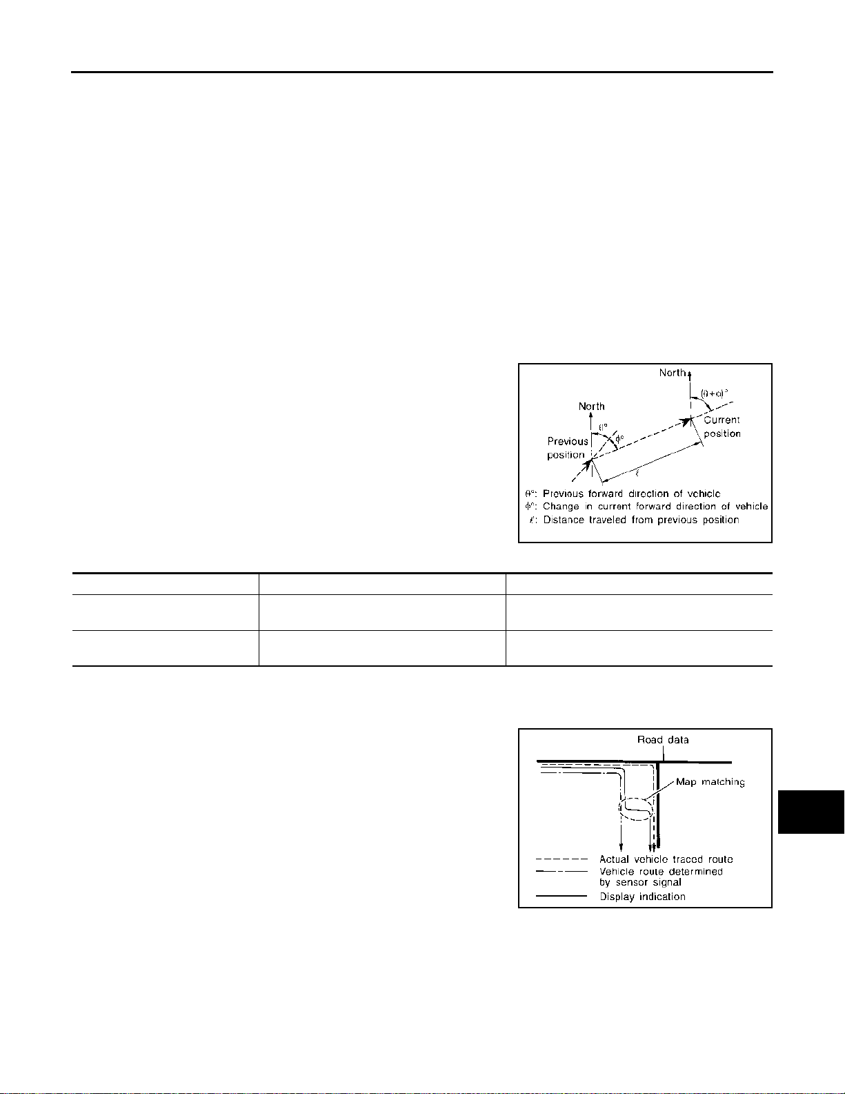
SYSTEM
< SYSTEM DESCRIPTION >
• The navigation system can be operated by control panel of the NAVI control unit and display (touch panel) of
the NAVI control unit.
• Guide sound during the operation of the navigation system is output from NAVI control unit to front speaker.
• NAVI control unit calculates the vehicle location based on the signals from GYRO (angle speed sensor),
vehicle sensor, and GPS satellite, as well as the map data from map SD card. It is displayed on display of
the NAVI control unit.
POSITION DETECTION PRINCIPLE
The navigation system periodically calculates the vehicle's current position according to the following three
signals:
• Travel distance of the vehicle as determined by the vehicle speed sensor
• Turning angle of the vehicle as determined by the gyroscope (angular velocity sensor)
• Direction of vehicle travel as determined by the GPS antenna (GPS information)
The current position of the vehicle is then identified by comparing the calculated vehicle position with map dat a
read from the map SD card (map-matching), and indicated on the screen as a vehicle mark. More accurate
data is judged and used by comparing vehicle position detection results found by the GPS with the result by
map-matching.
[WITH NAVIGATION]
A
B
C
D
E
The current vehicle position will be calculated by detecting the distance the vehicle moved from the previous calculation point and its
direction.
• Travel distance
Travel distance calculations are based on the vehicle speed sensor input signal. Therefore, the calculation may become incorrect
as the tires wear down. To prevent this, an automatic distance correction function has been adopted.
• Travel direction
Change in the travel direction of the vehicle is calculated by a gyroscope (angular velocity sensor) and a GPS antenna (GPS information). They have both advantages and disadvantages.
Type Advantage Disadvantage
Gyroscope
(angular velocity sensor)
GPS antenna
(GPS information)
Can detect the vehicle's turning angle quite
accurately.
Can detect the vehicle's travel direction
(North/South/East/West).
Direction errors may accumulate when vehicle is
driven for long distances without stopping.
Correct direction cannot be de tected when vehicle
speed is low.
SEL684V
More accurate traveling direction is detected because priorities are set for the signals from these two
devices according to the situation.
MAP-MATCHING
Map-matching compares a current location detected by the method
in the “Location Detection Principle” with a road map data from map
SD card.
NOTE:
The road map data is based on data stored in the map SD card.
F
G
H
I
J
K
L
M
AV
SEL685V
The vehicle position may not be corrected under the following circumstances and after driving for a certain
time when GPS information is difficult to receive.
AV-79
O
P
Page 85
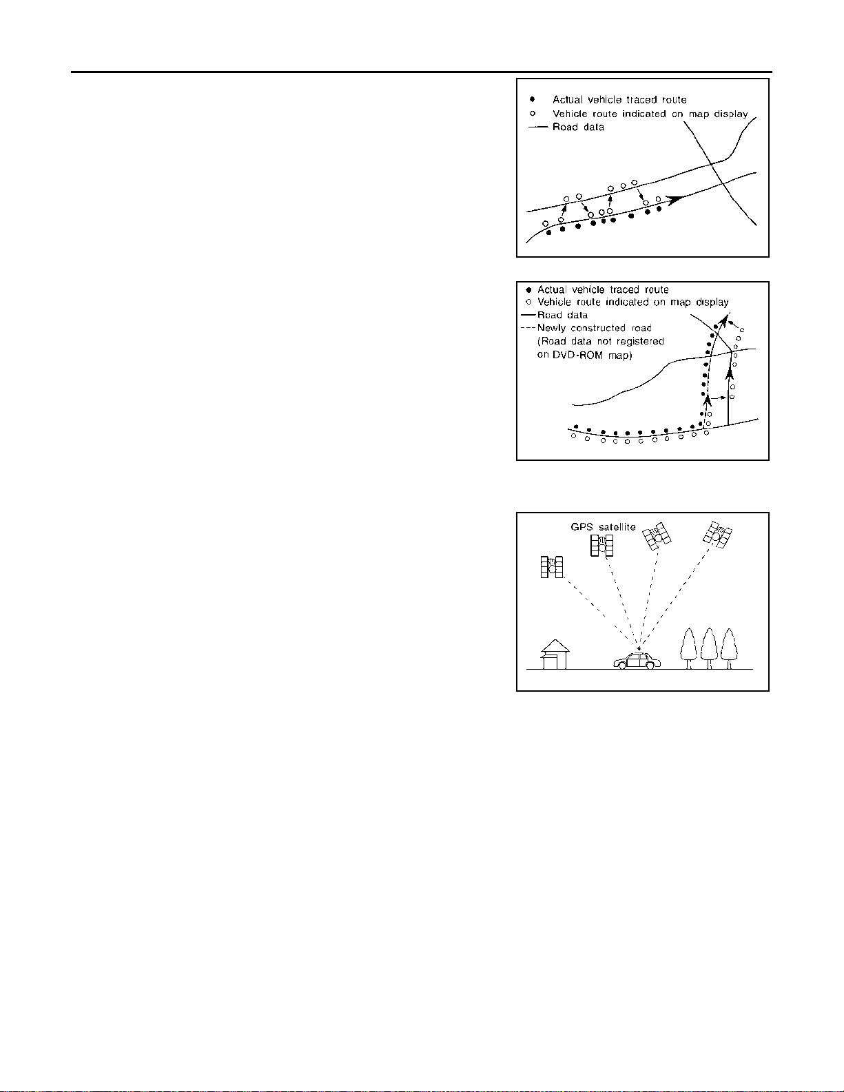
SYSTEM
< SYSTEM DESCRIPTION >
• In map-matching, alternative routes to reach the destination will be
shown and prioritized, after the road on which the vehicle is currently driven has been judged and the vehicle mark has been repositioned.
Alternative routes will be shown in different order of priority, and
the incorrect road can be avoided if there is an error in distance
and/or direction.
They are of the same priority if two roads are running in parallel.
Therefore, the vehicle mark may appear on either of them alternately, depending on maneuvering of the steering wheel and configuration of the road.
• Map-matching does not function correctly when a road on which
the vehicle is driving is new and not recorded in the map SD card,
or when road pattern stored in the map data and the actual road
pattern are different due to repair.
The map-matching function may find another road and position the
vehicle mark on it when driving on a road not present in the map.
Then, the vehicle mark may change to it when the correct road is
detected.
• Effective range for comparing the vehicle position and travel direction calculated by the distance and direction with the road data
read from the map SD card is limited. Therefore, correction by
map-matching is not possible when there is an excessive gap
between current vehicle position and the position on the map.
[WITH NAVIGATION]
SEL686V
SKIA0613E
GPS (Global Positioning System)
GPS (Global Positioning System) is developed for and is controlled
by the US Department of Defense. The system utilizes GPS satellites (NA VSTAR), transmitting out radio waves while flying on an orbit
around the earth at an altitude of approximately 21,000 km (13,049
mile).
The receiver calculates the travel position in three dimensions (latitude/longitude/altitude) according to the time lag of the radio waves
that four or more GPS satellites transmit (three-dimensional positioning). The GPS receiver calculates the travel position in two dimensions (latitude/longitude) with the previous altitude data if the GPS
receiver receives only three radio waves (two-dimensional positioning). GPS position correction is not performed while stopping the
SEL526V
vehicle.
Accuracy of the GPS will deteriorate under the following conditions:
• In two-dimensional positioning, GPS accuracy will deteriorate when altitude of the vehicle position changes.
• The position of GPS satellite affects GPS detection precision. The position detection may not be precisely
performed.
• The position detection is not performed if GPS receiver does not receive radio waves from GPS satellites.
(Inside a tunnel, parking in a building, under an elevated highway etc.) GPS receiver may not receive radio
waves from GPS satellites if any object is placed on the GPS antenna.
NOTE:
• The detection result has an error of approximately 10 m (32.81 ft) even with a high-precision three dimensional positioning.
• There may be cases when the accuracy is lowered and radio waves are stopped intentionally because the
GPS satellite signal is controlled by the US trace control center.
AUXILIARY INPUT FUNCTION
• Sound can be output from an external device by connecting a device with USB connector and AUX jack.
• AUX sound signals are transmitted to each speaker via NAVI control unit.
USB CONNECTION FUNCTION
• iPod or music files in USB memory can be played.
• Sound signals are transmitted to each speaker via NAVI control unit.
AV-80
Page 86

SYSTEM
< SYSTEM DESCRIPTION >
• iPod is recharged when connected to USB connector and AUX jack.
iPod is a trademark of Apple inc., registered in the U.S. and other countries.
NOTE:
Use the enclosed USB harness when connecting iPod to USB connector and AUX jack.
[WITH NAVIGATION]
A
SPEED SENSITIVE VOLUME SYSTEM
• Volume level of this system gone up and down automatically in proportion to the vehicle speed.
• The control level can be selected by the customer.
HANDS-FREE PHONE SYSTEM
• Hands-free communication can be operated by connecting to cellular phone using Bluetooth®.
• Operation is performed by steering switch.
• Guide sound that is heard during operation is output from NAVI control unit to front speaker.
METER DISPLAY
Audio Indicator
• The steering switch is connected to the combination meter.
• The combination meter transmits a steering switch signal to the NAVI control unit via AV communication
when the user operates the audio with the steering switch.
• The NAVI control unit changes the status of function according to the steeri ng switch operation when receiving a steering switch signal.
• The NAVI control unit transmits an meter display signal to the combination meter via AV communication and
displays the status of audio on the combination meter (in the information display) when the function is
changed by an operation.
Navigation Indicator
• When the navigation system is ON, the NAVI control unit transmits a meter display signal to the combination
meter via A V communication.
• The combination meter displays a navigation status on the combination meter (in the information display)
when receiving a meter display signal.
Hands-free Phone Indicator
• When a cell phone that is connected with the NAVI control unit via Bluetooth® communication receives a
phone call, the incoming call is displayed on the information display in combination meter.
®
• When NAVI control unit recognizes an incoming call from a cell phone via Bluetooth
transmits the meter display signal to combination meter via AV communication.
• When combination meter receives the meter display signal, it displays the incoming call of cell phone on
information display.
• When an incoming call is received, the driver can operate the steering switch to answer the phone.
• When steering switch is operated, the combination meter receives the steering switch signal, and then combination meter transmits the steering switch signal to the NAVI control unit via AV communication.
• When NAVI control unit receives the steering switch signal, it activates the hands-free phone.
communication, it
B
C
D
E
F
G
H
I
J
K
L
AROUND VIEW MONITOR FUNCTION
• This system is equipped with wide-angle cameras on the front and rear of the vehicle and on both right and
left door mirrors. The images from front view, rear view, front-side view (RH side), and birds-eye view that
shows the view from the top of the vehicle are displayed to monitor the vehicle surroundings.
• Around view monitor control unit cuts out and expands the image received from each camera to create each
view.
• In front view and rear view, the vehicle width, distance lines and predictive course lines are superimposed
and displayed. In front-side view, the vehicle distance guiding line and vehicle width guiding line are displayed.
• The Birds-Eye view converts the images from 4 cameras into the overhead view and displays the status of
the vehicle on display. The vehicle icon that are displayed on the Birds-Eye view display are rendered by
around view monitor control unit.
Around View Monitor Screen
• Around view monitor combines and displays the travel direction view and “Birds-Eye view”, “Front-Side
view”.
• Around view monitor control unit renders the view icon and warning message on display.
AV-81
M
AV
O
P
Page 87
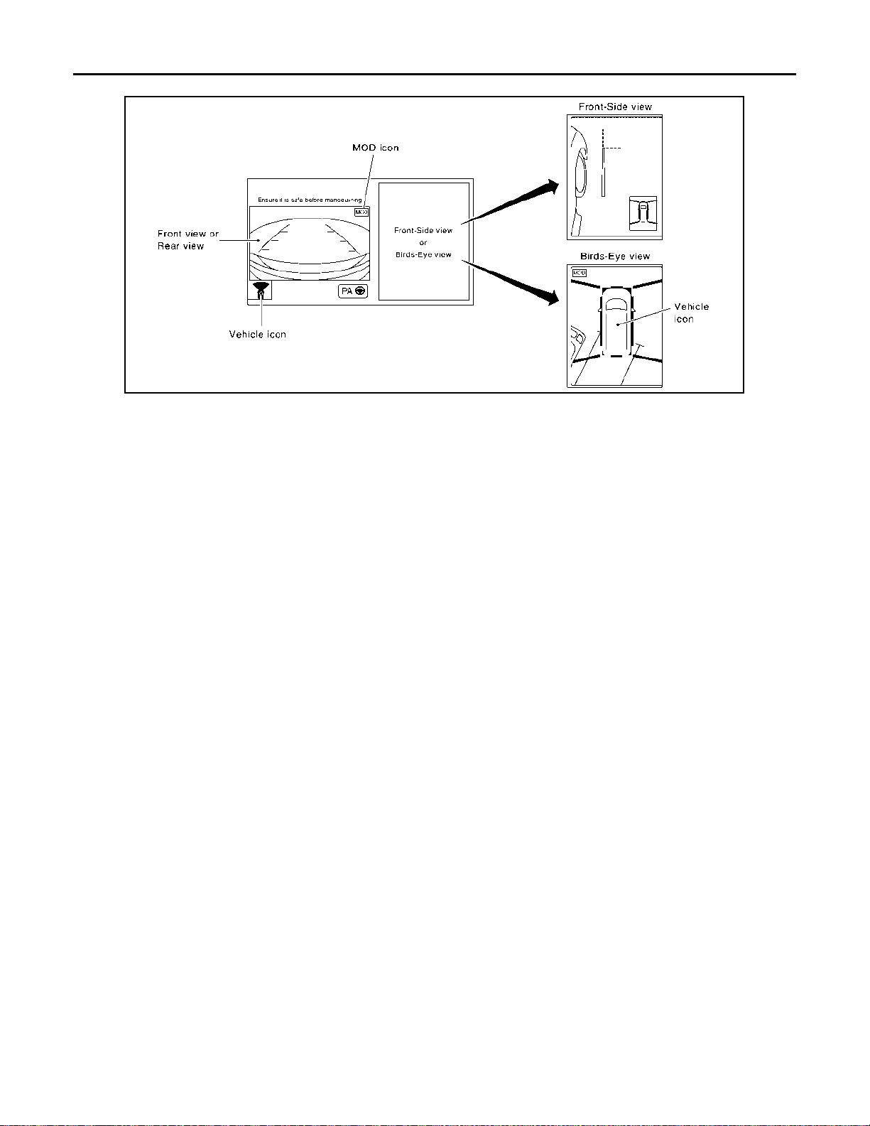
SYSTEM
< SYSTEM DESCRIPTION >
Screen constitution
NOTE:
There is the icon which is not displayed by specifications.
Operation Description
• Around view monitor operates by pressing the “CAMERA” switch or shifting the selector lever to the reverse
position.
• When the selector lever is in any position other than the reverse position, the screen is switched to the
around view monitor by pressing the “CAMERA” switch.
• The screen is switched to the around view monitor by shifting the selector lever to the reverse position.
• In the around view monitor, Birds-Eye view, Front-side view can be switched by pressing the “CAMERA”
switch.
• The around view monitor is cancelled 3 minutes after pressing the “CAMERA” switch or vehicle speed is
approximately 10 km/h (6 MPH), and then the screen returns to the screen before displaying the around
view monitor when selector lever is in a position other than the reverse position.
• In the Birds-Eye view, the invisible area is displayed to show the border of 4 camera images. In addition, red
fixed lines are displayed in 4 corners of the vehicle icon. After turning the ignition switch ON, the invisible
area is highlighted with yellow and red fixed lines are blink only once.
[WITH NAVIGATION]
JSNIA7282GB
AV-82
Page 88
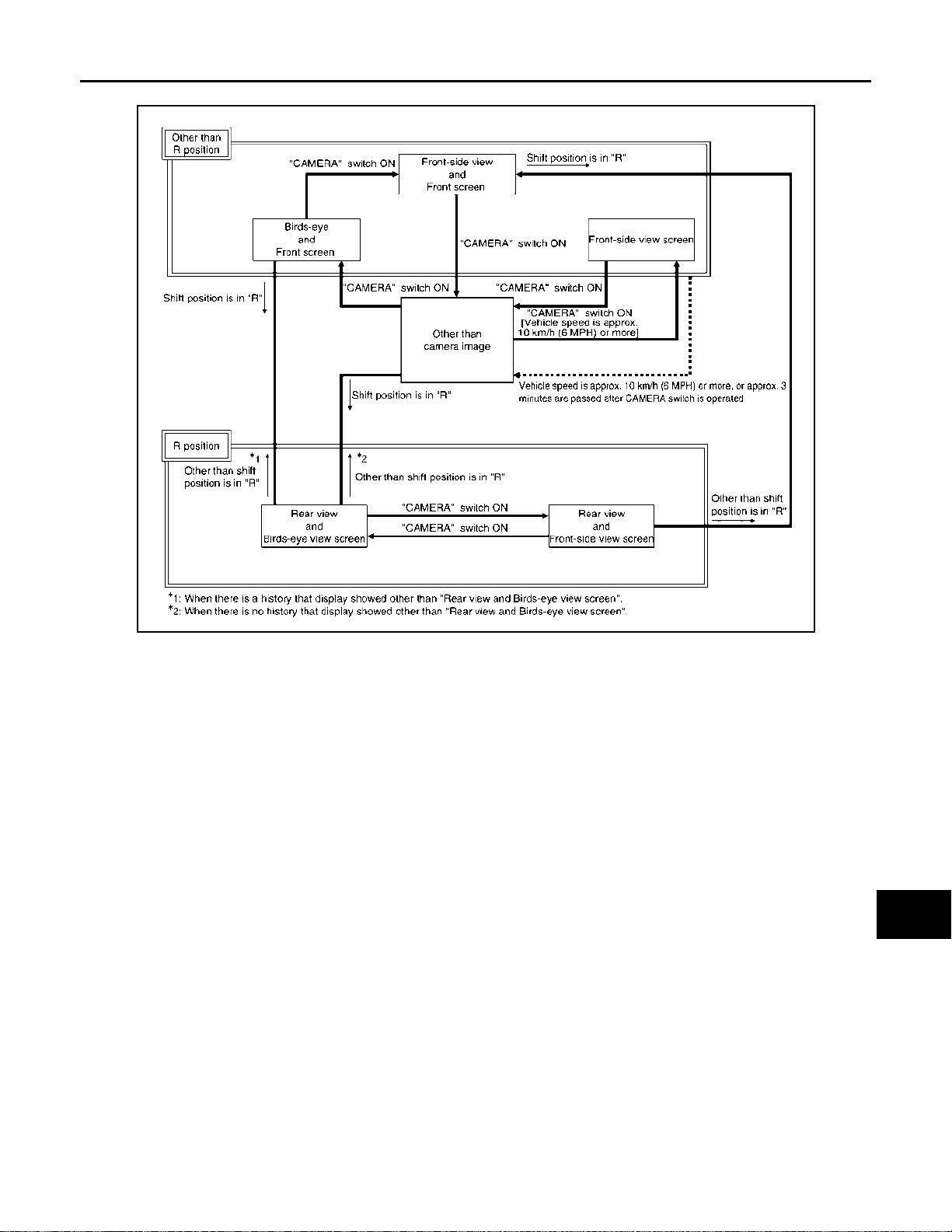
< SYSTEM DESCRIPTION >
SYSTEM
[WITH NAVIGATION]
Around view monitor screen transition
A
B
C
D
E
F
G
JSNIA7287GB
FRONT VIEW
• The front view image is from the front camera.
• When the selector lever is in any position other than the reverse position, the front view is displayed by
pressing the “CAMERA” switch. It improves the visibility of obstacles in front of the vehicle and helps driving
by the images displayed from Birds-Eye view and Front-Side view.
• Display the vehicle width guiding line and vehicle distance guiding line in front view and display the predictive course line according to the steering angle.
• If the steering angle is within approximately 90 degrees, the predictive course lines on the left/right side are
displayed. If the steering angle is exceeding approximately 90 degrees, only the predictive course line on the
outside (in the opposite side of steering direction) is displayed.
• Around view monitor control unit receives the steering angle signal from steering angle sensor via CAN communication, and controls the direction and distance of the predictive course line.
• ON/OFF setting of predictive course line can be performed by CONSULT.
H
I
J
K
L
M
AV
O
AV-83
P
Page 89
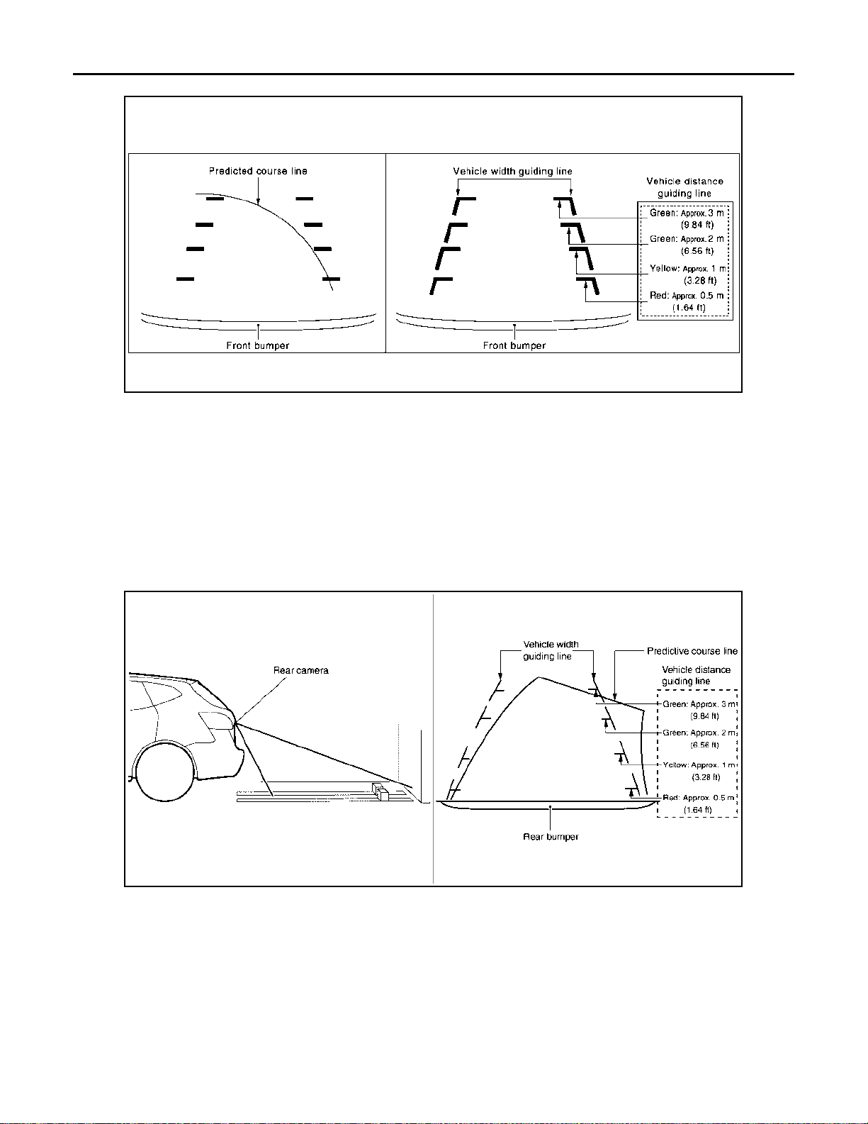
SYSTEM
< SYSTEM DESCRIPTION >
Front view guiding lines
REAR VIEW
• The rear view image is from the rear camera.
• When the selector lever is in the reverse position, the rear view is displayed. Backing and parking are
improved by the images from Birds-Eye view and Front-Side view.
• Display the vehicle width guiding line and vehicle distance guiding line in Rear view and display the predictive course line according to the steering angle.
• The predictive course line is not displayed at the steering neutral position.
• Around view monitor control unit receives the steering angle signal from steering angle sensor via CAN communication, and controls the direction and distance of the predictive course line.
• ON/OFF setting of predictive course line can be performed by CONSULT.
[WITH NAVIGATION]
JSNIA0770GB
Rear view guiding lines
JSNIA4567GB
MOVING OBJECT DETECTION (MOD)
• Moving Object Detection (MOD) is a function that notifies the driver of the presence of moving objects in the
area around the vehicle. MOD detects moving objects from camera image, illuminates frame of view in yellow whenever “MOD” icon is displayed in blue, and sounds buzzer in combination meter.
• MOD detects moving objects while camera image is displayed on display.
• Around view monitor control unit performs the following process when moving objects are detected.
- Superimposes yellow frame line on camera image signal and outputs them to display.
- Transmits buzzer output signal to combination meter via CAN communication so that buzzer in combination
meter sounds.
• Around view monitor control unit detects moving objects from camera image according to an image recognition method called optical flow.
AV-84
Page 90

SYSTEM
< SYSTEM DESCRIPTION >
• MOD does not detect a background as a moving object when the vehicle moves (when whole screen
moves), but detects a moving object when an actual moving object is displayed on screen.
• MOD can be set to permanent OFF by the following operation.
- Permanent OFF: Settings can be performed on the information display of the combination meter.
• Color of “MOD” icon indicates whether or not MOD is operative. “MOD” icon is displayed as shown in the following table. When MOD is operative, “MOD” icon is displayed in blue. When MOD is not operative, “MOD”
icon is displayed in gray or orange. MOD icon is not displayed when MOD is off (permanent off).
• MOD illuminates frame of view in yellow and sounds buzzer , when any of the conditions in the following t able
are satisfied.
[WITH NAVIGATION]
A
B
C
Operation Condition
Shift position Vehicle speed
P and N position 0 km/h (0 MPH) Birds-eye view
R position
D position
0 km/h (0 MPH) or more - less than 8
km/h (5 MPH)
0 km/h (0 MPH) or more - less than 8
km/h (5 MPH)
View where MOD is operative
Rear view
Front view
• MOD does not operate or stops operation when any of the conditions in the following table are satisfied.
“MOD” icon is displayed in gray or orange.
Operation stop condition
Front or rear door is open. Gray Operation of Birds-eye view stops when door is open.
Back door is open. Gray Operation of Birds-eye view and rear view stops when back door is open.
Rear camera installation
angle is incorrect
Front camera image is
abnormal (Temporary)
Side camera image is ab-
normal (Temporary)
Rear camera image is ab-
normal (Temporary)
System malfunction Orange Refer to AV-120, "
“MOD” icon
color
Gray
Gray
Gray
Gray
Note
Operation of rear view stop s when rea r view ca mera inst al lation an gle is
incorrect.
Operation of Birds-eye view and front view stops when front camera image is temporarily abnormal.
Operation of Birds-eye view stop s when side camera image is tempo rarily abnormal.
Operation of Birds-eye view and rear vi ew stops when rear camera image
is temporarily abnormal.
DTC Index"
D
E
F
G
H
I
J
K
FRONT-SIDE VIEW
• The front-side view image is from the side camera RH. (LHD models)
• The front-side view image is from the side camera LH. (RHD models)
• In Front-Side view, display the vehicle dist ance guiding line and vehicle width guiding line.
AV-85
L
M
AV
O
P
Page 91
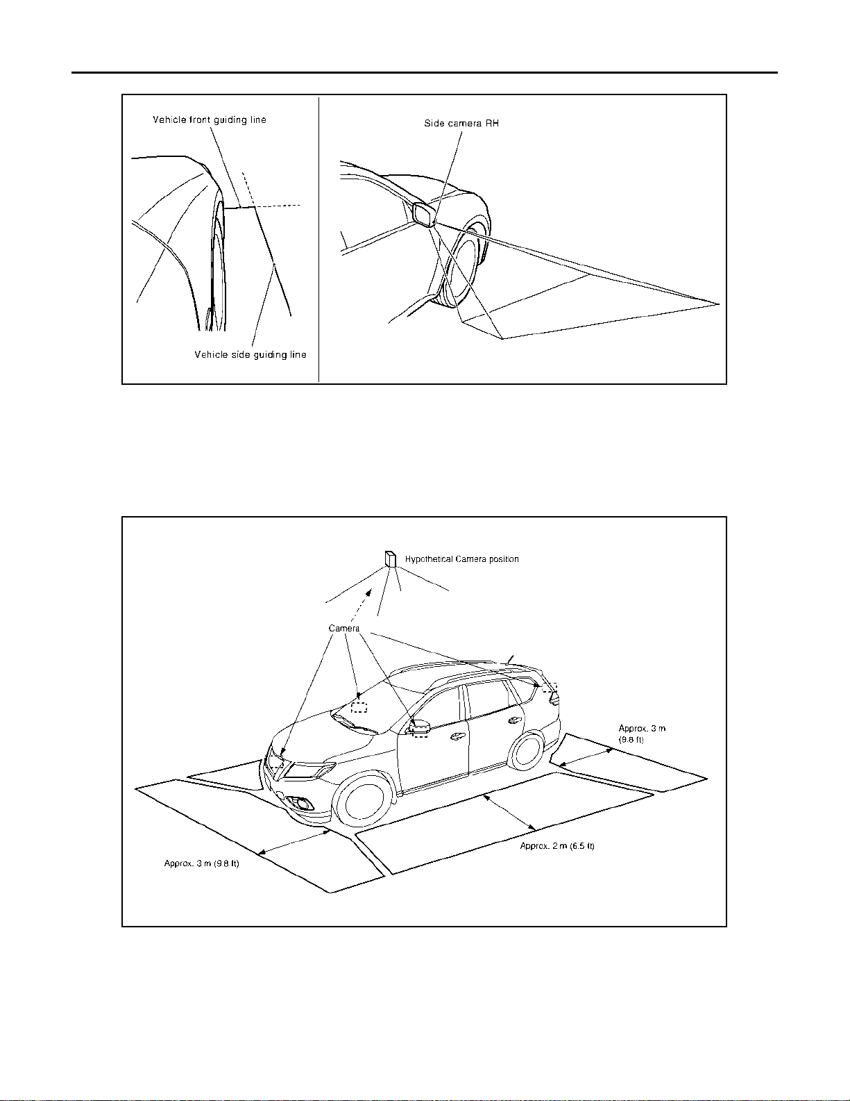
SYSTEM
< SYSTEM DESCRIPTION >
Front-side view area and guiding line
NOTE:
RHD model displays a image from side camera LH.
BIRDS-EYE VIEW
• The image from the 4 cameras is cut out and converted into the overhead view, and the surroundings of the
vehicle is displayed in birds-eye view.
• In Birds-Eye view, the invisible area is displayed on the image to specify the boundary of the 4 cameras.
[WITH NAVIGATION]
JSNIA0771GB
Birds-Eye view display image
AV-86
AWNIA3345GB
Page 92
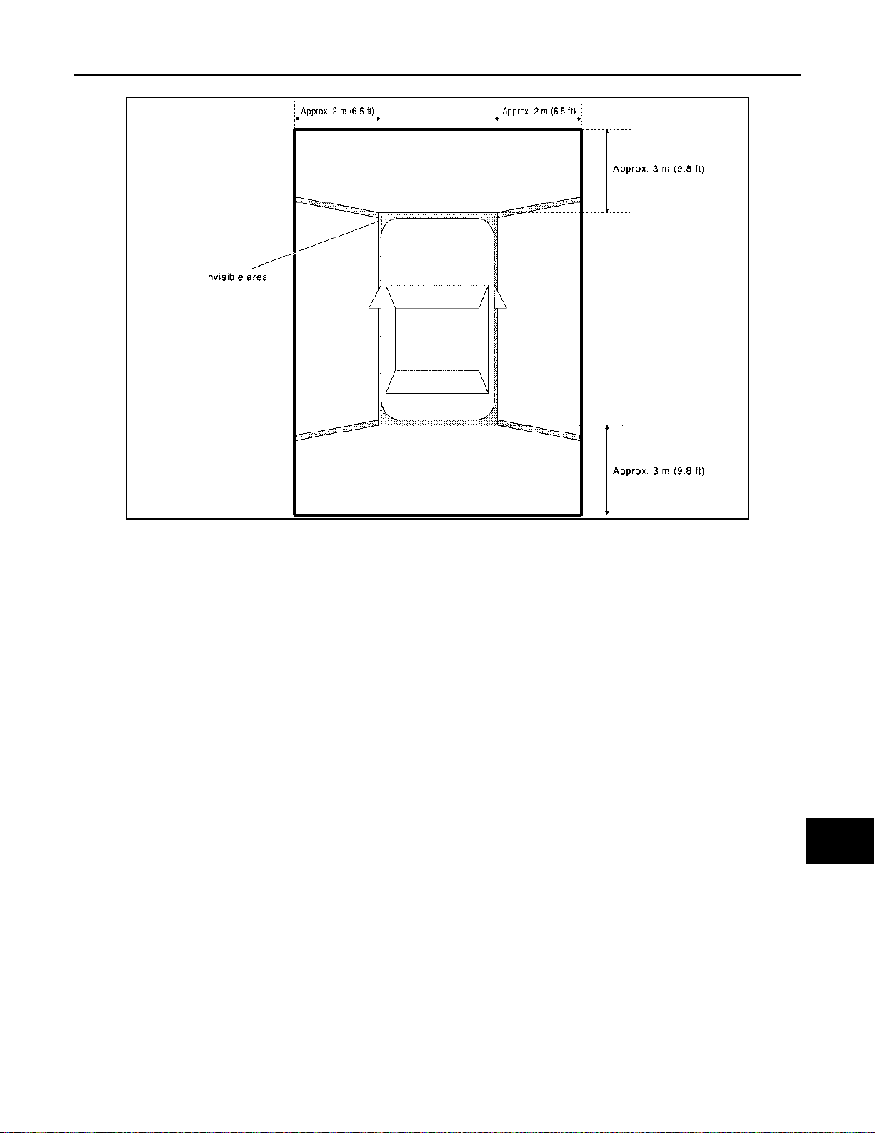
< SYSTEM DESCRIPTION >
SYSTEM
[WITH NAVIGATION]
Birds-Eye view display area
A
B
C
D
E
F
G
JSNIA3986GB
Camera Image Operation Principle
• If the camera image calibration is incomplete, the applicable camera position is indicated as an error on the
Birds-Eye view display. (Calibration operation is necessary when replacing each camera or when replacing
around view monitor control unit.)
• Around view monitor control unit receives the camera switch signal via CAN communication from NAVI control unit by pressing the “CAMERA” switch.
• Around view monitor control unit that receives the camera switch signal supplies the power to each camera
and inputs the camera image from each camera.
• When the selector lever is in the reverse position, around view monitor control unit receives the reverse signal, supplies the power to each camera, and inputs the camera image from each camera.
• Around view monitor control unit that receives the camera image signal from each camera cuts out the
required screen for each view, superimposes the camera image, vehicle icon, guiding lines, and outputs
them to the NAVI control unit.
Precautions for Vehicle Width Guide Line and Predictived Course Line Display on The Rear View Monitor Display
Side distance guide lines and predictive course line on the display may be different from actual lines depending on vehicle conditions and road conditions.
PRECAUTIONS FOR ROAD CONDITIONS
H
I
J
K
L
M
AV
O
AV-87
P
Page 93
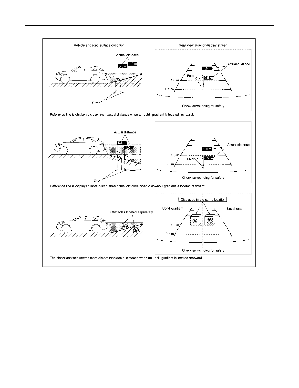
SYSTEM
< SYSTEM DESCRIPTION >
• Since guide lines and predictive course line are drawn based on the road, a different distance may be displayed if a protruding block is present nearby.
[WITH NAVIGATION]
PRECAUTIONS FOR BLOCK
JSNIA3995GB
AV-88
Page 94
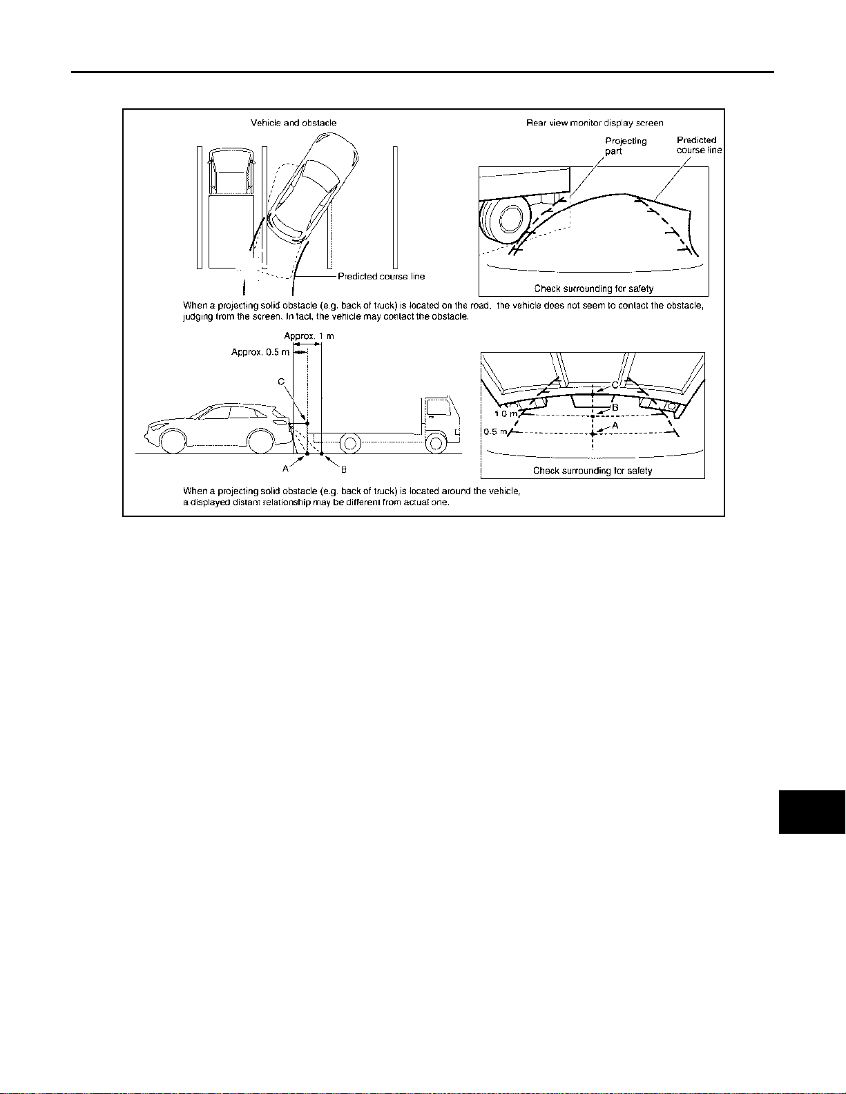
SYSTEM
< SYSTEM DESCRIPTION >
• Since guide lines and predictive course line are drawn based on the road, a different distance may be displayed if a protruding block is present nearby.
[WITH NAVIGATION]
A
B
C
D
E
F
G
JSNIA3996GB
H
I
J
K
L
M
AV
O
AV-89
P
Page 95
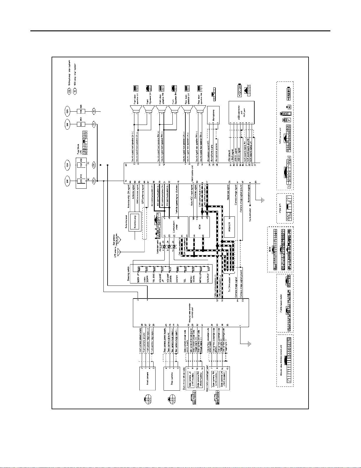
< SYSTEM DESCRIPTION >
SYSTEM
[WITH NAVIGATION]
Circuit Diagram
WITHOUT BSW
INFOID:0000000010714802
AV-90
JSNIA7360GB
Page 96
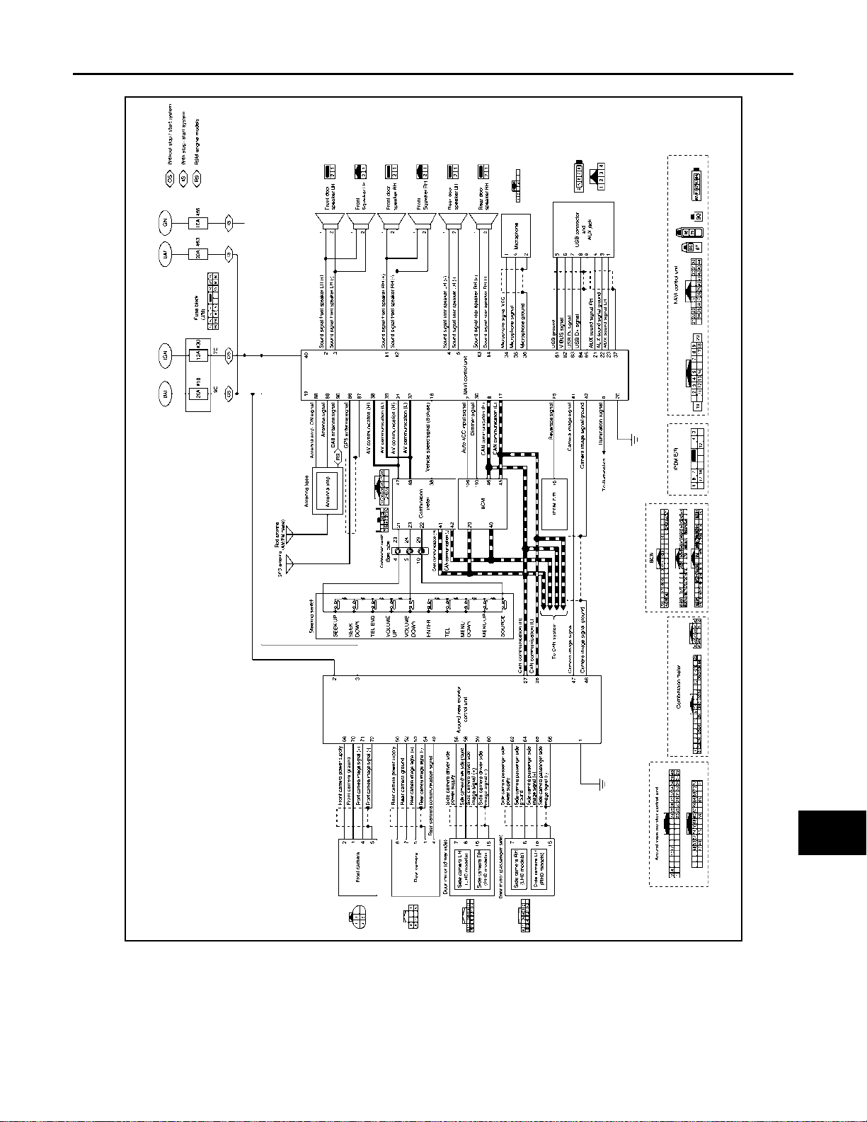
< SYSTEM DESCRIPTION >
WITH BSW
SYSTEM
[WITH NAVIGATION]
A
B
C
D
E
F
G
AV
H
I
J
K
L
M
O
JSNIA7361GB
Fail-Safe (NAVI Control Unit) INFOID:0000000010828199
If a malfunction occurs in the multi-AV system, NAVI control unit performs fail-safe activation according to the
detected malfunction.
AV-91
P
Page 97

SYSTEM
< SYSTEM DESCRIPTION >
Detection item Multi-AV system operation in fail-safe mode DTC
The system using the CAN communication signal from control unit which cannot
CAN communication
NAVI control unit
Configuration
GPS antenna The vehicle positions of a navigation screen differ. U1244
AV communication
DAB radio antenna DAB radio is not received.
USB connector Audio equipment which connected to USB does not operate. U1263
Radio antenna Radio is not received. U12AB
communicate does not function.
The system using the CAN communication signal does not function. U1010
The function of some multi -AV systems does not operate.
NOTE:
Symptom other than an item may occur.
A function of NAVI control unit becomes mismatched with a vehicle specification and
destination.
The system of ECU which detected abnormalities does not operate. U1300
The system which is using AV communication does not operate. U1310
[WITH NAVIGATION]
U1000
U1217
U1229
U12AC
U12AD
U12AE
U12AF
U12B0
U12B1
U12AA
U122F
U12B2
Fail-Safe (Around View Monitor Control Unit)
DTC
Display contents of CONSULT
C1A00
CONTROL UNIT
C1A01
POWER SUPPLY CIRC
C1A03
VHCL SPEED SE CIRC
C1A04
ABS/TCS/VDC CIRC
C1A07
CVT CIRCUIT
C1A39
STRG SEN CIR
C1A56
SONAR CIRC
Malfunction detection condition Fail-safe condition
Around view monitor control unit internal malfunction
• The battery voltage sent to around view monitor control unit remains less than 7.9 V for 5
seconds
• The battery voltage sent to around view monitor control unit remains more than 19.3 V for
5 seconds
If the vehicle speed signal (wheel speed) from
ABS actuator and electric unit (control unit) received by the around view monitor control unit
via CAN communication, are inconsistent
If a malfunction occurs in the VDC/TCS/ABS
system
If the CVT is malfunction
If the steering angle sensor is malfunction
The around view monitor control unit detects
that sonar control unit has a malfunction
INFOID:0000000010828200
Around view monitor with Park Assist is cancel
Around view monitor with Park Assist is cancel
• BSW system is cancel
• DAA system is stopped.
• MOD (Moving Object Detection) func tion is
cancel
• Around view monitor with Park Assist is
cancel
• BSW system is cancel
• DAA system is stopped.
• MOD (Moving Object Detection) func tion is
cancel
• Around view monitor with Park Assist is
cancel
Around view monitor with Park Assist is cancel
• BSW system is cancel
• DAA system is stopped.
• MOD (Moving Object Detection) func tion is
cancel
Around view monitor with Park Assist is cancel
AV-92
Page 98

< SYSTEM DESCRIPTION >
SYSTEM
[WITH NAVIGATION]
DTC
Display contents of CONSULT
U0122
VDC P-RUN DIAGNOSIS
U0416
VDC CHECKSUM DIAGNOSIS
U0428
ST ANGLE SENSOR CALIBRATION
U1000
CAN COMM CIRCUIT
U1010
CONTROL UNIT (CAN)
U111A
REAR CAMERA IMAGE SIGNAL
U111B
SIDE CAMERA RH IMAGE SIGNAL
U111C
FRONT CAMERA IMAGE SIGNAL
Malfunction detection condition Fail-safe condition
• BSW system is cancel
If around view monitor control unit detects an
error signal that is received from ABS actuator
and electric unit (control unit) via CAN communication
If around view monitor control unit detects an
error signal that is received from ABS actuator
and electric unit (control unit) via CAN communication
Neutral position adjustment of steering angle
sensor is not complete.
When around view monitor control unit cannot
transmit/receive CAN communication signal
continuously for 2 seconds or more.
CAN initial diagnosis malfunction is detected.
No-signal status of rear camera imag e signal is
continued for 500 ms or more while ignition
switch is ON.
NOTE:
Current malfunction is displayed only and is not
saved.
No-signal status of side camera RH image signal is continued for 500 ms or more while ignition switch is ON.
NOTE:
Current malfunction is displayed only and is not
saved.
No-signal status of front ca mera image signal is
continued for 500 ms or more while ignition
switch is ON.
NOTE:
Current malfunction is displayed only and is not
saved.
• DAA system is stopped.
• MOD (Moving Object Detection) function is
cancel
• Around view monitor with Park Assist is
cancel
• BSW system is cancel
• DAA system is stopped.
• MOD (Moving Object Detection) function is
cancel
• Around view monitor with Park Assist is
cancel
• Predicted course line is not displayed.
• MOD (Moving Object Detection) function is
stopped.
• BSW system is stopped.
• DAA system is stopped.
• Around view monitor with Park Assist is
stopped
The following functions are stopped
• When communication of steering angle
sensor signal is not normal
- Predicted course line is not displayed.
- MOD (Moving Object Detection) function is
stopped.
- BSW system is stopped.
- DAA system is stopped.
• When communication of vehicle signal,
wheel speed sensor signal, and shift signal
is not normal
- Predicted course line is not displayed.
- MOD (Moving Object Detection) function is
stopped.
- LDW system is stopped.
- BSW system is stopped.
- DAA system is stopped.
- Around view monitor with Park Assist is
stopped
MOD (Moving Object Detection) function is
stopped.
• Camera image is not displayed (Gray
screen display).
• MOD (Moving Object Detection) function is
stopped.
Camera image is not displayed (G ray screen
display).
Camera image is not displayed (G ray screen
display).
A
B
C
D
E
F
G
H
I
J
K
L
M
AV
O
P
AV-93
Page 99

< SYSTEM DESCRIPTION >
SYSTEM
[WITH NAVIGATION]
DTC
Display contents of CONSULT
U111D
SIDE CAMERA LH IMAGE SIGNAL
U112F
EPS CIRCUIT
U1232
ST ANGLE SEN CALIB
U1302
CAMERA POWER VOLT
U1304
CAMERA IMAGE CALIB
U1305
CONFIG UNFINISH
U1308
R-CAMERA (R&L) CALIB JDGMNT
U1309
PUMP INPUT CURRENT JUDGE
U130A PUMP ECU JUDGE If the pump control unit is malfunction BSW system is stopped.
U130B
RR CAMERA COMM ERROR
U1320
REPROGRAMMING
U150E
BCM CIRCUIT
U1971
SONAR MESSAGE COUNTER
DIAG
Malfunction detection condition Fail-safe condition
No-signal status of side camera LH image signal is continued for 500 ms or more while ignition switch is ON.
NOTE:
Current malfunction is displayed only and is not
saved.
If the EPS system is malfunction
Neutral position adjustment of steering angle
sensor is performed. NG signal from steering
angle sensor is received.
Camera power supply voltage does not satisfy
the following conditions for 2 seconds or more
when ignition switch is turned ON.
• When camera power supply output is ON: 5.9
- 6.5 V
• When OFF: 0 V by camera power supply
measurement.
• When camera calibration is incomplete.
• When camera information in around view
monitor control unit and information read
from camera are not the same.
NOTE:
Current malfunction is displayed only and is not
saved.
The vehicle setting of around view monitor control unit is incomplete.
NOTE:
Current malfunction is displayed only and is not
saved.
Camera image calibration is incomplete
Around view monitor control unit detects the
value of current from pump control unit is incorrect
Around view monitor control unit receives the
incorrect communication signal from rear view
camera
Reprogramming of around view monito r control
unit is incomplete
If the BCM is malfunction
Around view monitor control unit receives an in-
correct signal from sonar control unit via CAN
communication
Camera image is not displayed (Gray screen
display).
Around view monitor with Park Assist is cancel
• Predicted course line is not displayed.
• MOD (Moving Object Detection) func tion is
stopped.
• BSW system is stopped.
• DAA system is stopped.
• Around view monitor with Park Assist is
stopped.
Camera power output is stopped
• Unmatched icon display (red) is displayed (applicable for unmatched camera
only).
• Around view monitor with Park Assist is
cancel.
• On applicable camera screen marking
(Red) is displayed.
• Around view monitor with Park Assist is
cancel.
• MOD (Moving Object Detection) func tion is
stopped.
• BSW system is stopped.
• Around view monitor with Park Assist is
stopped.
BSW system is stopped.
• MOD (Moving Object Detection) func tion is
stopped.
• BSW system is stopped.
Around view monitor with Park Assist is cancel
Around view monitor with Park Assist is cancel
Around view monitor with Park Assist is cancel
AV-94
Page 100

< SYSTEM DESCRIPTION >
SYSTEM
[WITH NAVIGATION]
DTC
Display contents of CONSULT
U1972
EPS MESSAGE COUNTER DIAG
Other
Malfunction detection condition Fail-safe condition
Around view monitor control u nit receives an incorrect signal from EPS control unit via CAN
communication
When around view monitor control unit is not
normal.
Around view monitor with Park Assist is cancel
Switch to camera screen is not allowed.
A
B
C
D
E
F
G
H
AV
I
J
K
L
M
O
P
AV-95
 Loading...