

Page 1
QUICK REFERENCE INDEX
Publication Number:
SM7E00-1T31E0E
MODEL T31 SERIES
© 2007 NISSAN EUROPE S.A.S.
All rights reserved. No part of this Electronic Service Manual may be reproduced or stored in a retrieval system, or transmitted in any form,
or by any means, electronic, mechanical, photocopying, recording or otherwise, without the prior written permission of Nissan Europe
S.A.S., Paris, France.
A GENERAL INFORMATION
B ENGINE
D TRANSMISSION
& DRIVELINE
E SUSPENSION
F BRAKES
G STEERING
H RESTRAINTS
I VENTILATION, HEATER
& AIR CONDITIONER
J BODY INTERIOR
K BODY EXTERIOR, DOOR,
ROOF & VEHICLE SECURITY
L DRIVER CONTROLS
M ELECTRICAL &
POWER CONTROL
N DRIVER INFORMATION
& MULTIMEDIA
P MAINTENANCE
GI General Information
EM Engine Mechanical
LU Engine Lubrication System
CO Engine Cooling System
EC Engine Control System
FL Fuel System
EX Exhaust System
STR Starting System
ACC Accelerator Control System
CL Clutch
TM Transaxle & Transmission
DLN Driveline
FAX Front Axle
RAX Rear Axle
FSU Front Suspension
RSU Rear Suspension
WT Road Wheels & Tires
BR Brake System
PB Parking Brake System
BRC Brake Control System
ST Steering System
STC Steering Control System
SB Seat Belt
SBC Seat Belt Control System
SR SRS Airbag
SRC SRS Airbag Control System
VTL Ventilation System
HA Heater & Air Conditioning System
HAC Heater & Air Conditioning Control System
INT Interior
IP Instrument Panel
SE Seat
DLK Door & Lock
SEC Security Control System
GW Glass & Window System
PWC Power Window Control System
RF Roof
EXT Exterior
MIR Mirrors
EXL Exterior Lighting System
INL Interior Lighting System
WW Wiper & Washer
DEF Defogger
HRN Horn
PWO Power Outlet
BCS Body Control System
LAN LAN System
LNL LAN System (LHD)
LNR LAN System (RHD)
PCS Power Control System
CHG Charging System
PG Power Supply, Ground & Circuit Elements
MWI Meter, Warning Lanp & Indicator
WCS Warning Chime System
AV Audio, Visual & Navigation System
MA Maintenance
A
B
C
D
E
F
G
H
I
J
K
L
M
M
N
O
P
Page 2

FOREWORD
This manual contains maintenance and repair procedures for the NISSAN
X-TRAIL,modelT31 series.
In order to assure your safety and the efficient functioning of the vehicle,
this manual should be read thoroughly. It is especially important that the
PRECAUTIONS in the GI section be completely understood before starting
any repair task.
All information in this manual is based on the latest product information
at the time of publication. The right is reserved to make changes in specifications and methods at any time without notice.
IMPORTANT SAFETY NOTICE
The proper performance of service is essential for both the safety of the
technician and the efficient functioning of the vehicle.
The service methods in this Service Manual are described in such a manner that the service may be performed safely and accurately.
Service varies with the proceduresused,theskillsof the technician and the
tools and parts available. Accordingly, anyone using service procedures,
tools or parts which are not specifically recommended by NISSAN must
first be completely satisfied that neither personal safety nor the vehicle’s
safety will be jeopardized by the service method selected.
NISSAN EUROPE S.A.S.
Service Engineering Section
Paris, France
Page 3

ENGINE
A
ACC
SECTION ACC
ACCELERATOR CONTROL SYSTEM
CONTENTS
PRECAUTION ...............................................2
PRECAUTIONS ...................................................2
Precaution for Supplemental Restraint System
(SRS) "AIR BAG" and "SEAT BELT PRE-TEN-
SIONER" ...................................................................
ON-VEHICLE REPAIR .................................. 3
ACCELERATOR CONTROL SYSTEM .............. 3
Exploded View ..........................................................3
Removal and Installation ..........................................3
2
Inspection ................................................................. 4
C
D
E
F
G
H
I
J
M
N
O
K
L
P
ACC-1
Page 4

PRECAUTIONS
< PRECAUTION >
PRECAUTION
PRECAUTIONS
Precaution for Supplemental Restraint System (SRS) "AIR BAG" and "SEAT BELT
PRE-TENSIONER" INFOID:0000000001205438
The Supplemental Restraint System such as “AIR BAG” and “SEAT BELT PRE-TENSIONER”, used along
with a front seat belt, helps to reduce the risk or severity of injury to the driver and front passenger for certain
types of collision. Information necessary to service the system safely is included in the “SRS AIRBAG” and
“SEAT BELT” of this Service Manual.
WARNING:
• To avoid rendering the SRS inoperative, which could increase the risk of personal injury or death in
the event of a collision which would result in air bag inflation, all maintenance must be performed by
an authorized NISSAN/INFINITI dealer.
• Improper maintenance, including incorrect removal and installation of the SRS, can lead to personal
injury caused by unintentional activation of the system. For removal of Spiral Cable and Air Bag
Module, see the “SRS AIRBAG”.
• Do not use electrical test equipment on any circuit related to the SRS unless instructed to in this
Service Manual. SRS wiring harnesses can be identified by yellow and/or orange harnesses or harness connectors.
ACC-2
Page 5
< ON-VEHICLE REPAIR >
ACCELERATOR CONTROL SYSTEM
ON-VEHICLE REPAIR
ACCELERATOR CONTROL SYSTEM
Exploded View INFOID:0000000001160876
A
ACC
C
D
E
F
G
H
JPBIA0893GB
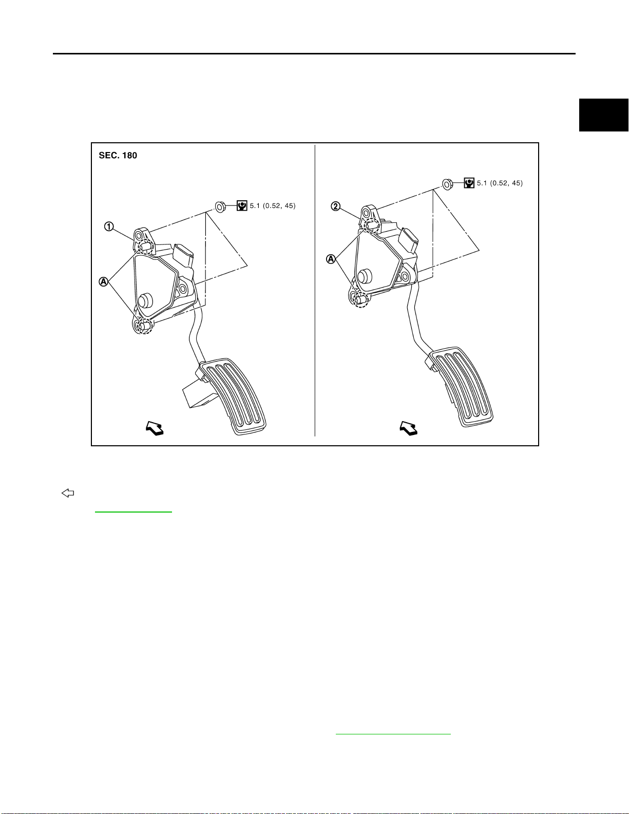
1. Accelerator pedal assembly (LHD models) 2. Accelerator pedal assembly (RHD models)
A. Locating pin
: Vehicle front
Refer to GI-4, "
Components" for symbols in the figure.
Removal and Installation INFOID:0000000001160877
REMOVAL
LHD models
1. Loosen accelerator pedal assembly mounting nuts, and remove accelerator pedal assembly.
CAUTION:
• Never disassemble accelerator lever. Never remove accelerator pedal position sensor from
accelerator lever.
• Avoid impact from dropping etc. during handling.
• Be careful to keep accelerator lever away from water.
2. Disconnect accelerator pedal position sensor harness connector.
RHD models
1. Disconnect accelerator pedal position sensor harness connector.
2. Remove accelerator pedal assembly mounting nuts.
3. Loosen brake pedal assembly mounting nuts. Refer to BR-67, "
NOTE:
Brake pedal assembly does not have to be removed from the vehicle.
4. Remove accelerator pedal assembly.
Exploded View".
I
J
K
L
M
N
O
P
ACC-3
Page 6

ACCELERATOR CONTROL SYSTEM
< ON-VEHICLE REPAIR >
CAUTION:
• Never disassemble accelerator lever. Never remove accelerator pedal position sensor from
accelerator lever.
• Avoid impact from dropping etc. during handling.
• Be careful to keep accelerator lever away from water.
INSTALLATION
Note the following, and install in the reverse order of removal.
• Insert locating pin into vehicle side to position accelerator pedal assembly . Tighten mounting nuts to accelerator pedal assembly.
Inspection INFOID:0000000001160878
INSPECTION AFTER INSTALLATION
• Check that accelerator pedal moves smoothly within the whole operation range when it is depressed fully
and released.
• Check that accelerator pedal returns securely to the fully released position.
• For the electrical inspection of accelerator pedal position sensor. Refer to ECM-268, "
(MR20DE), ECQ-275, "Description" (QR25DE) or ECR-242, "Description" (M9R).
Description"
ACC-4
Page 7

DRIVER INFORMATION & MULTIMEDIA
A
B
SECTION AV
AUDIO, VISUAL & NAVIGATION SYSTEM
CONTENTS
AUDIO WITHOUT NAVIGATION
BASIC INSPECTION ....................................
DIAGNOSIS AND REPAIR WORKFLOW .......... 6
Work Flow .................................................................6
FUNCTION DIAGNOSIS ...............................7
AUDIO SYSTEM .................................................. 7
System Diagram ........................................................7
System Description ...................................................7
Component Parts Location ........................................9
Component Description ................................ .... .......10
DIAGNOSIS SYSTEM (AUDIO UNIT) ................11
Diagnosis Description (With Hands-free Phone
System) ...................................................................
COMPONENT DIAGNOSIS .........................12
11
Component Inspection .............................................18
ECU DIAGNOSIS .........................................19
6
AUDIO UNIT ......................................................19
Reference Value ......................................................19
Wiring Diagram—AUDIO WITHOUT NAVIGA-
TION SYSTEM (LHD MODELS)— ..........................
Wiring Diagram—AUDIO WITHOUT NAVIGA-
TION SYSTEM (RHD MODELS)— .........................
SYMPTOM DIAGNOSIS ..............................33
MULTI AV SYSTEM SYMPTOMS ....................33
Symptom Table .......................................................33
NORMAL OPERATING CONDITION ...............34
Description ....................... ...... ....... ...... ....... ...... ........34
PRECAUTION ..............................................36
21
27
C
D
E
F
G
H
I
J
K
POWER SUPPLY AND GROUND CIRCUIT ......12
AUDIO UNIT ...................................... .... ... .................12
AUDIO UNIT : Diagnosis Procedure .......................12
MICROPHONE SIGNAL CIRCUIT .....................13
Description ..............................................................13
Diagnosis Procedure .......... .....................................13
STEERING SWITCH SIGNAL A CIRCUIT .........14
Description ..............................................................14
Diagnosis Procedure .......... .....................................14
Component Inspection ............................................14
STEERING SWITCH SIGNAL B CIRCUIT .........16
Description ..............................................................16
Diagnosis Procedure .......... .....................................16
Component Inspection ............................................16
STEERING SWITCH SIGNAL GND CIRCUIT ....18
Description ..............................................................18
Diagnosis Procedure .......... .....................................18
PRECAUTIONS .................................................36
Precaution for Supplemental Restrain t Syste m
(SRS) "AIR BAG" and "SEAT BELT PRE-TEN-
SIONER" .................................................................
ON-VEHICLE REPAIR .................................37
AUDIO UNIT ......................................................37
Exploded View .........................................................37
Removal and Installation .........................................37
FRONT DOOR SPEAKER ................................38
Exploded View .........................................................38
Removal and Installation .........................................38
REAR DOOR SPEAKER ..................................39
Exploded View .........................................................39
Removal and Installation .........................................39
TWEETER .........................................................40
Exploded View .........................................................40
Removal and Installation .........................................40
AV-1
36
L
M
AV
O
P
Page 8

STEERING SWITCH .......................................... 41
Exploded View ........ ... ... ... ... .... ................................ 41
Removal and Installation ........................................ 41
MICROPHONE ...................................................42
Exploded View ........ ... ... ... ... .... ................................ 42
Removal and Installation ........................................ 42
RADIO ANTENNA .............................................43
Exploded View ........ ... ... ... ... .... ................................ 43
Removal and Installation ........................................ 43
ANTENNA FEEDER (RADIO) ........................... 44
Harness Layout ......................................................44
AUDIO WITH NAVIGATION
System Diagram .............. ... ... .... ............................. 57
System Description ................................ .... ... ... ... ....57
Component Parts Location .....................................58
Component Description .......................................... 59
AUDIO SYSTEM ................................................ 60
System Diagram .............. ... ... .... ............................. 60
System Description ................................ .... ... ... ... ....60
Component Parts Location .....................................61
Component Description .......................................... 62
DIAGNOSIS SYSTEM (NAVI CONTROL
UNIT) ..................................................................
Diagnosis Description ......................................... ....63
CONSULT - III Function (MULTI AV) ......................74
63
BASIC INSPECTION ................................... 45
DIAGNOSIS AND REPAIR WORKFLOW ......... 45
Work Flow ........ ... .... ................................................ 45
INSPECTION AND ADJUSTMENT ................... 47
ADDITIONAL SERVICE WHEN REMOVING BAT-
TERY NEGATIVE TERMINAL .................. ... ... .... ......
ADDITIONAL SERVICE WHEN REMOVING
BATTERY NEGATIVE TERMINAL : Description ....
ADDITIONAL SERVICE WHEN REMOVING
BATTERY NEGATIVE TERMINAL : Special Re-
pair Requirement ....................................................
ADDITIONAL SERVICE WHEN REPLACING
CONTROL UNIT ........................................................
ADDITIONAL SERVICE WHEN REPLACING
CONTROL UNIT : Description ................................
ADDITIONAL SERVICE WHEN REPLACING
CONTROL UNIT : Special Repair Requirement .....
REAR VIEW MONITOR POSSIBLE ROUTE LINE
CENTER POSITION ADJUSTMENT ........................
REAR VIEW MONITOR POSSIBLE ROUTE LINE
CENTER POSITION ADJUSTMENT : Description
REAR VIEW MONITOR POSSIBLE ROUTE LINE
CENTER POSITION ADJUSTMENT : Special Re-
pair Requirement ....................................................
...
47
47
47
47
47
47
47
47
47
FUNCTION DIAGNOSIS ............................. 48
MULTI AV SYSTEM ........................................... 48
System Diagram ........................ ... ... .... ................... 48
System Description .............................. ................... 48
Component Parts Location ..................................... 50
Component Description .......................................... 51
NAVIGATION SYSTEM ..................................... 52
System Diagram ........................ ... ... .... ................... 52
System Description .............................. ................... 52
Component Parts Location ..................................... 55
Component Description .......................................... 56
REAR VIEW MONITOR SYSTEM ..................... 57
COMPONENT DIAGNOSIS ....................... 78
U1000 CAN COMM CIRCUIT ............................ 78
Description .............................................................. 78
DTC Logic .............................................. .... ... ..........78
Diagnosis Procedu re ..............................................78
U1010 CONTROL UNIT (CAN) ......................... 79
Description .............................................................. 79
DTC Logic .............................................. .... ... ..........79
Diagnosis Procedure ..... ... .......................................79
U1310 NAVI CONTROL UNIT ........................... 80
Description .............................................................. 80
DTC Logic .............................................. .... ... ..........80
U1200 NAVI CONTROL UNIT ........................... 81
Description .............................................................. 81
DTC Logic .............................................. .... ... ..........81
U1201 NAVI CONTROL UNIT ........................... 82
Description .............................................................. 82
DTC Logic .............................................. .... ... ..........82
U1216 NAVI CONTROL UNIT ........................... 83
Description .............................................................. 83
DTC Logic .............................................. .... ... ..........83
U1217 NAVI CONTROL UNIT ........................... 84
Description .............................................................. 84
DTC Logic .............................................. .... ... ..........84
U1204 GPS ........................................................ 85
Description .............................................................. 85
DTC Logic .............................................. .... ... ..........85
Diagnosis Procedure ..... ... .......................................85
U1205 GPS ........................................................ 86
Description .............................................................. 86
DTC Logic .............................................. .... ... ..........86
Diagnosis Procedure ..... ... .......................................86
U1206 GPS ........................................................ 87
Description .............................................................. 87
DTC Logic .............................................. .... ... ..........87
Diagnosis Procedure ..... ... .......................................87
AV-2
Page 9

U1207 GPS .........................................................88
Description ..............................................................88
DTC Logic ...............................................................88
Diagnosis Procedure .......... .... ... ..............................88
U1208 NAVI CONTROL UNIT ............................89
Description ..............................................................89
DTC Logic ...............................................................89
Diagnosis Procedure .......... .... ... ..............................89
U1209 NAVI CONTROL UNIT ............................90
Description ..............................................................90
DTC Logic ...............................................................90
Diagnosis Procedure .......... .... ... ..............................90
U120A NAVI CONTROL UNIT ...........................91
Description ..............................................................91
DTC Logic ...............................................................91
Diagnosis Procedure .......... .... ... ..............................91
U120C NAVI CONTROL UNIT ...........................92
Description ..............................................................92
DTC Logic ...............................................................92
Diagnosis Procedure .......... .... ... ..............................92
U120D NAVI CONTROL UNIT ...........................93
Description ..............................................................93
DTC Logic ...............................................................93
Diagnosis Procedure .......... .... ... ..............................93
U120E NAVI CONTROL UNIT ...........................94
Description ..............................................................94
DTC Logic ...............................................................94
Diagnosis Procedure .......... .... ... ..............................94
U120F NAVI CONTROL UNIT ...........................95
Description ..............................................................95
DTC Logic ...............................................................95
Diagnosis Procedure .......... .... ... ..............................95
U1210 NAVI CONTROL UNIT ............................96
Description ..............................................................96
DTC Logic ...............................................................96
Diagnosis Procedure .......... .... ... ..............................96
U1211 NAVI CONTROL UNIT ............................97
Description ..............................................................97
DTC Logic ...............................................................97
Diagnosis Procedure .......... .... ... ..............................97
U1212 NAVI CONTROL UNIT ............................98
Description ..............................................................98
DTC Logic ...............................................................98
Diagnosis Procedure .......... .... ... ..............................98
U1213 NAVI CONTROL UNIT ............................99
Description ..............................................................99
DTC Logic ...............................................................99
Diagnosis Procedure .......... .... ... ..............................99
U1214 NAVI CONTROL UNIT ..........................100
Description ............................................................100
DTC Logic ..............................................................100
Diagnosis Procedure .............................................100
U1215 NAVI CONTROL UNIT ........................101
Description .......................... ... ....... ...... ....... ...... ......101
DTC Logic ..............................................................101
Diagnosis Procedure .............................................101
U1243 DISPLAY UNIT .................................... 102
Description .......................... ... ....... ...... ....... ...... ......102
DTC Logic ..............................................................102
Diagnosis Procedure .............................................102
U1244 GPS ANTENNA ...................................104
Description .......................... ... ....... ...... ....... ...... ......104
DTC Logic ..............................................................104
Diagnosis Procedure .............................................104
U1250 CAMERA CONTROL UNIT ................. 105
Description .......................... ... ....... ...... ....... ...... ......105
DTC Logic ..............................................................105
Diagnosis Procedure .............................................105
U1300 AV COMM CIRCUIT ............................ 106
Description .......................... ... ....... ...... ....... ...... ......106
POWER SUPPLY AND GROUND CIRCUIT .. 107
NAVI CONTROL UNIT .............................................107
NAVI CONTROL UNIT : Diagnosis Procedure ......107
AUDIO UNIT ............. ... .... ... ... ... ................................107
AUDIO UNIT : Diagnosis Procedure .....................107
DISPLAY UNIT .........................................................108
DISPLAY UNIT : Diagnosis Procedure ..................108
CAMERA CONTROL UNIT ......................................108
CAMERA CONTROL UNIT : Diagno sis Procedure
..
108
RGB (R: RED) SIGNAL CIRCUIT ...................110
Description .......................... ... ....... ...... ....... ...... ......110
Diagnosis Procedure .............................................110
RGB (G: GREEN) SIGNAL CIRCUIT ............. 111
Description .......................... ... ....... ...... ....... ...... ......111
Diagnosis Procedure .............................................111
RGB (B: BLUE) SIGNAL CIRCUIT ................. 112
Description .......................... ... ....... ...... ....... ...... ......112
Diagnosis Procedure .............................................112
RGB SYNCHRONIZING SIGNAL CIRCUIT ... 113
Description .......................... ... ....... ...... ....... ...... ......113
Diagnosis Procedure .............................................113
RGB AREA (YS) SIGNAL CIRCUIT ............... 114
Description .......................... ... ....... ...... ....... ...... ......114
Diagnosis Procedure .............................................114
HORIZONTAL SYNCHRONIZING (HP) SIG-
NAL CIRCUIT ..................................................
115
A
B
C
D
E
F
G
H
I
J
K
L
M
AV
O
P
AV-3
Page 10

Description ....................... .......................... ............115
Diagnosis Procedure .............................................115
VERTICAL SYNCHRONIZING (VP) SIGNAL
CIRCUIT ...........................................................
Description ....................... .......................... ............116
Diagnosis Procedure .............................................116
116
MICROPHONE SIGNAL CIRCUIT .................. 117
Description ....................... .......................... ............117
Diagnosis Procedure .............................................117
CAMERA IMAGE SIGNAL CIRCUIT (REAR
VIEW CAMERA TO CAMERA CONTROL
UNIT) ................................................................
Description ....................... .......................... ............118
Diagnosis Procedure .............................................118
118
CAMERA IMAGE SIGNAL CIRCUIT (CAM-
ERA CONTROL UNIT TO DISPLAY UNIT) ....
Description ....................... .......................... ............119
Diagnosis Procedure .............................................119
119
AUDIO UNIT .....................................................161
Reference Value ................................................... 161
Wiring Diagram—AUDIO WITH NAVIGATION
SYSTEM (LHD MODELS)— .................................
Wiring Diagram—AUDIO WITH NAVIGATION
SYSTEM (RHD MODELS)— ................................
164
177
DISPLAY UNIT .................................................190
Reference Value ................................................... 190
Wiring Diagram—AUDIO WITH NAVIGATION
SYSTEM (LHD MODELS)— .................................
Wiring Diagram—AUDIO WITH NAVIGATION
SYSTEM (RHD MODELS)— ................................
193
206
CAMERA CONTROL UNIT ..............................219
Reference Value ................................................... 219
Wiring Diagram—AUDIO WITH NAVIGATION
SYSTEM (LHD MODELS)— .................................
Wiring Diagram—AUDIO WITH NAVIGATION
SYSTEM (RHD MODELS)— ................................
222
235
SYMPTOM DIAGNOSIS ...........................248
CAMERA ON SIGNAL CIRCUIT ..................... 120
Description ....................... .......................... ............120
Diagnosis Procedure .............................................120
STEERING ANGLE SENSOR SIGNAL 1, 2
CIRCUIT ...........................................................
Description ....................... .......................... ............121
Diagnosis Procedure .............................................121
121
STEERING ANGLE SENSOR SIGNAL 3 CIR-
CUIT .................................................................
Description ....................... .......................... ............123
Diagnosis Procedure .............................................123
123
STEERING SWITCH SIGNAL A CIRCUIT ...... 124
Description ....................... .......................... ............124
Diagnosis Procedure .............................................124
Component Inspection ...........................................124
STEERING SWITCH SIGNAL B CIRCUIT ...... 126
Description ....................... .......................... ............126
Diagnosis Procedure .............................................126
Component Inspection ...........................................126
STEERING SWITCH SIGNAL GND CIRCUIT . 128
Description ....................... .......................... ............128
Diagnosis Procedure .............................................128
Component Inspection ...........................................128
ECU DIAGNOSIS .......................................130
NAVI CONTROL UNIT ..................................... 130
Reference Value ..... ... ....................................... .....130
Wiring Diagram—AUDIO WITH NAVIGATION
SYSTEM (LHD MODELS)— .................................
Wiring Diagram—AUDIO WITH NAVIGATION
SYSTEM (RHD MODELS)— .................................
DTC Index .............................................................159
134
147
MULTI AV SYSTEM SYMPTOMS ....................248
Symptom Table ..................................................... 248
NORMAL OPERATING CONDITION ............... 251
Description ............................................................ 251
PRECAUTION ...........................................255
PRECAUTIONS ................................................255
Precaution for Supplemental Restraint System
(SRS) "AIR BAG" and "SEAT BELT PRE-TEN-
SIONER" ............................. ..................................
Precaution for Trouble Diagnosis .......................... 255
Precaution for Harness Repair .............................. 255
255
ON-VEHICLE REPAIR ..............................256
AUDIO UNIT .....................................................256
Exploded View ...................................................... 256
Removal and Installation ..................................... .. 256
NAVI CONTROL UNIT .....................................257
Exploded View ...................................................... 257
Removal and Installation ..................................... .. 257
DISPLAY UNIT .................................................258
Exploded View ...................................................... 258
Removal and Installation ..................................... .. 258
FRONT DOOR SPEAKER ................................259
Exploded View ...................................................... 259
Removal and Installation ..................................... .. 259
REAR DOOR SPEAKER ..................................260
Exploded View ...................................................... 260
Removal and Installation ..................................... .. 260
TWEETER .........................................................261
Exploded View ...................................................... 261
AV-4
Page 11

Removal and Installation ........ ... ... ... ......................
261
STEERING SWITCH ........................................262
Exploded View ......................................................262
Removal and Installation ........ ... ... ... ......................262
MICROPHONE .................................................263
Exploded View ......................................................263
Removal and Installation ........ ... ... ... ......................263
CAMERA CONTROL UNIT ..............................264
Exploded View ......................................................264
Removal and Installation ........ ... ... ... ......................264
Adjustment ............................................................264
Removal and Installation .......................................265
Adjustment .......................... ....... ...... ...... ....... ...... ...265
STEERING ANGLE SENSOR .........................267
Exploded View .......................................................267
Removal and Installation .......................................267
RADIO ANTENNA ........................................... 268
Exploded View .......................................................268
Removal and Installation .......................................268
GPS ANTENNA ............................................... 269
Harness Layout .....................................................269
Removal and Installation .......................................269
A
B
C
D
REAR VIEW CAMERA .....................................265
Exploded View ......................................................265
ANTENNA FEEDER ........................................270
Harness Layout .....................................................270
E
F
G
H
I
J
K
L
AV-5
M
AV
O
P
Page 12

DIAGNOSIS AND REPAIR WORKFLOW
< BASIC INSPECTION >
[AUDIO WITHOUT NAVIGATION]
BASIC INSPECTION
DIAGNOSIS AND REPAIR WORKFLOW
Work Flow INFOID:0000000001092892
DETAILED FLOW
1.CHECK SYMPTOM
Check the malfunction symptoms by performing the following items.
• Interview the customer to obtain the malfunction information (conditions and environment when the malfunction occurred).
• Check the symptom.
>> GO TO 2.
2.PERFORM DIAGNOSIS BY SYMPTOM
Perform the relevant diagnosis referring to the diagnosis chart by symptom. Refer to AV-33, "
>> GO TO 3.
Symptom Table".
3.REPAIR OR REPLACE MALFUNCTIONING PARTS
Repair or replace the malfunctioning parts.
>> GO TO 4.
4.FINAL CHECK
Perform the operation to check that the malfunction symptom is solved or any other symptoms are present.
Is there any symptom?
YES >> GO TO 2.
NO >> INSPECTION END
AV-6
Page 13
< FUNCTION DIAGNOSIS >
AUDIO SYSTEM
[AUDIO WITHOUT NAVIGATION]
FUNCTION DIAGNOSIS
AUDIO SYSTEM
System Diagram INFOID:0000000001092893
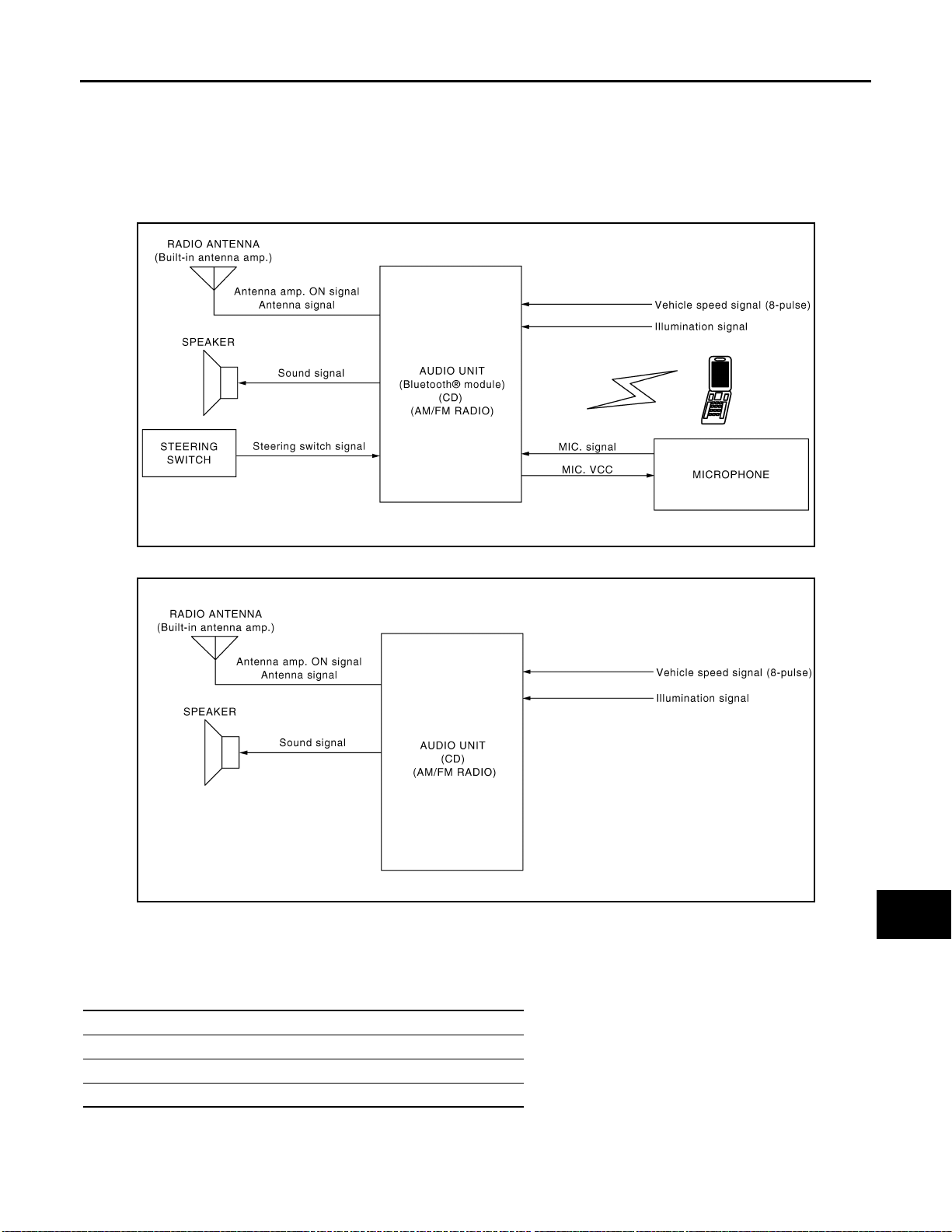
WITH HANDS-FREE PHONE SYSTEM
JPNIA0249GB
WITHOUT HANDS-FREE PHONE SYSTEM
A
B
C
D
E
F
G
H
JPNIA0250GB
System Description INFOID:0000000001092894
The audio system is equipped with following function. Each function is operated with audio switch or steering
switch (with hands-free phone system).
Function
AM/FM radio
CD
HANDS-FREE PHONE (WITH HANDS-FREE PHONE SYSTEM)
I
J
K
L
M
AV
O
P
FUNCTION DESCRIPTION
Operating signal
AV-7
Page 14

AUDIO SYSTEM
< FUNCTION DIAGNOSIS >
Audio system operation can be performed with audio switch or steering switch (with hands-free phone system).
AM/FM Radio Mode
• AM/FM radio tuner is built into audio unit.
• Audio signal is received by antenna, next it is amplified by antenna amp., and finally it is input to audio unit.
Audio unit outputs the audio signal to each speaker.
CD Mode
• CD function is built into audio unit.
• Audio unit outputs audio signal to each speaker when CD is inserted to audio unit.
Hands-free Phone System (with hands-free phone system)
• Hands-free communication can be operated by connecting using Bluetooth® with cellular phone.
• Operation is performed by steering switch.
When a call is originated
• Spoken voice sound output from the microphone (mic. signal) is input to audio unit. Audio uni t output s to cel -
®
lular phone with Bluetooth
communication as a TEL voice signal. Voice sound is then heard at the other
party.
When receiving a call
• Voice sound is input to own cellular phone from the other party. TEL voice signal is output to front speaker,
and the signal is input to audio unit by establishing Bluetooth
®
communication from cellular phone.
[AUDIO WITHOUT NAVIGATION]
SPEED SENSITIVE VOLUME
Volume level of this system gone up and down automatically in proportion to the vehicle speed. And the control level can be selected by the customer.
NATS AUDIO LINK
Description
The link with the NATS IMMU implies that the audio unit can basically only be operated if connected to the
matching NATS IMMU to which the audio unit was initially fitted on the production line.
Since radio operation is impossible after the link with the NATS is disrupted, theft of the audio unit is basically
useless since special equipment is required to reset the audio unit.
Initialization Process for Audio Units That Are Linked to the NATS IMMU
New audio units will be delivered to the factories in the “NEW” state, i.e. ready to be linked with the vehicle's
NA TS. When the audio unit in “NEW” state is first switched on at the factory, it will start up communication with
the vehicle's immobilizer control unit (IMMU) and send a code (the “Audio Unit Code”) to the IMMU. The IMMU
will then store this code, which is unique to each audio unit, in its (permanent) memory.
Upon receipt of the code by the IMMU, the NATS will confirm correct receipt of the audio unit code to the audio
unit. Hereafter, the audio unit will operate as normal.
During the initialization process, “NEW” is displayed on the audio unit display. Normally though, communication between audio unit and IMMU takes such a short time (300 ms) that the audio unit seems to switch on
directly without showing “NEW” on its display.
Normal Operation
Each time the audio unit is switched on afterwards, the audio unit code will be verified between the audio unit
and the NATS before the audio unit becomes operational. During the code verification process, “WAIT” is
shown on the audio unit display. Again, the communication takes such a short time (300 ms) that the audio
unit seems to switch on directly without showing “WAIT” on its display.
When The Radio Is Locked
In case of the audio unit being linked with the vehicle's NATS (immobilizer system), disconnection of the link
between the audio unit and the IMMU will cause the audio unit to switch into the lock (“SECURE”) mode in
which the audio unit is fully inoperative. Hence, repair of the audio unit is basically impossible, unless the
audio unit is reset to the “NEW” state for which special decoding equipment is required.
Clarion has provided their authorized service representatives with so called “decoder boxes” which can bring
the audio unit back to the “NEW” state, enabling the audio unit to be switched on after which repair can be performed. Subsequently, when the repaired audio unit is delivered to the final user again, it will be in the “NEW”
state to enable re-linking the audio unit to the vehicle's immobilizer system. As a result of the above, repair of
the audio unit can only be done by an authorized Clarion representative (when the owner of the vehicle
requests repair and can show personal identification).
AV-8
Page 15
AUDIO SYSTEM
< FUNCTION DIAGNOSIS >
Service Procedure
Item Service procedure Description
Battery disconnection No additional action required. –
Radio needs repair Repair needs to be done by authorized rep-
resentative of radio manufacturer since radio cannot be operated unless it is reset to
NEW state, using special decoding equip-
ment.
Replacement of radio by new part No additional action required. Radio is delivered in “NEW” state.
Transferring radio to another vehicle/re-
placement of radio by an old part
Replacement of IMMU Radio needs to be reset to NEW state by
No communication from IMMU to radio 1. Check NATS system if NATS is mal-
When initialized between ECM and IMMU. Radio needs to be reset to “NEW” status by
Radio needs to be reset to NEW state by
authorized representative of radio manu-
facturer.
authorized representative of Clarion.
functioning.
2. Reset radio to “NEW” state by authorized representative of Clarion after
NATS is repaired.
authorized representative of Clarion.
[AUDIO WITHOUT NAVIGATION]
–
–
After switching on the radio, it will display
“SECURE” after 1 minute.
The radio will display “SECURE” after 1
minute after switching on the radio. Further
use of radio is impossible until c om mun i cation is established again, or after radio is reset by authorized represent at iv e of Cl ari on.
It will display “SECURE” after 1 minute after
switching on the radio.
A
B
C
D
E
F
G
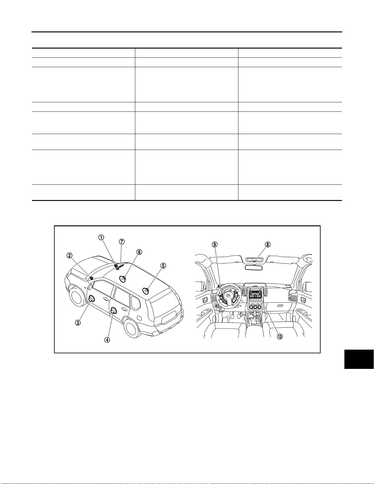
Component Parts Location INFOID:0000000001092895
JPNIA0316ZZ
1. Tweeter RH 2. Tweeter LH 3. Front do or speaker LH
4. Rear door speaker LH 5. Rear door speaker RH 6. Front door speaker RH
7. Radio antenna 8. Microphone* 9. Steering switch*
10. Audio unit
H
I
J
K
L
M
AV
O
*: With hands-free phone system
P
AV-9
Page 16

< FUNCTION DIAGNOSIS >
AUDIO SYSTEM
[AUDIO WITHOUT NAVIGATION]
Component Description
Part name Description
AUDIO UNIT
FRONT DOOR SPEAKER
REAR DOOR SPEAKER
TWEETER
STEERING SWITCH*
MICROPHONE*
RADIO ANTENNA (Built-in antenna amp.)
*: With hands-free phone system
INFOID:0000000001092896
• Operational switch of audio system is integrated.
• Receiving function of AM/FM radio, replaying function of CD and hands-free
phone function are integr ated.
• Audio signals are output to each speak er.
• Outputs sound signal from audio unit.
• Outputs high, mid and low range sounds.
• Outputs sound signal from audio unit.
• Outputs high, mid and low range sounds.
• Outputs sound signal from audio unit.
• Outputs high range sound.
• Operations for audio and hands-free phone are possible.
• Steering switch signal (operation signal) is output to audio unit.
• Used for hands-free phone operation.
• Mic. signal is sent to audio unit.
• Power (Mic. VCC) is supplied from audio unit.
• Radio signal received by radio antenna is amplified and sent to audio unit.
• Power (antenna amp ON signal) is supplied from audio unit.
AV-10
Page 17
< FUNCTION DIAGNOSIS >
DIAGNOSIS SYSTEM (AUDIO UNIT)
[AUDIO WITHOUT NAVIGATION]
DIAGNOSIS SYSTEM (AUDIO UNIT)
Diagnosis Description (With Hands-free Phone System) INFOID:0000000001178860
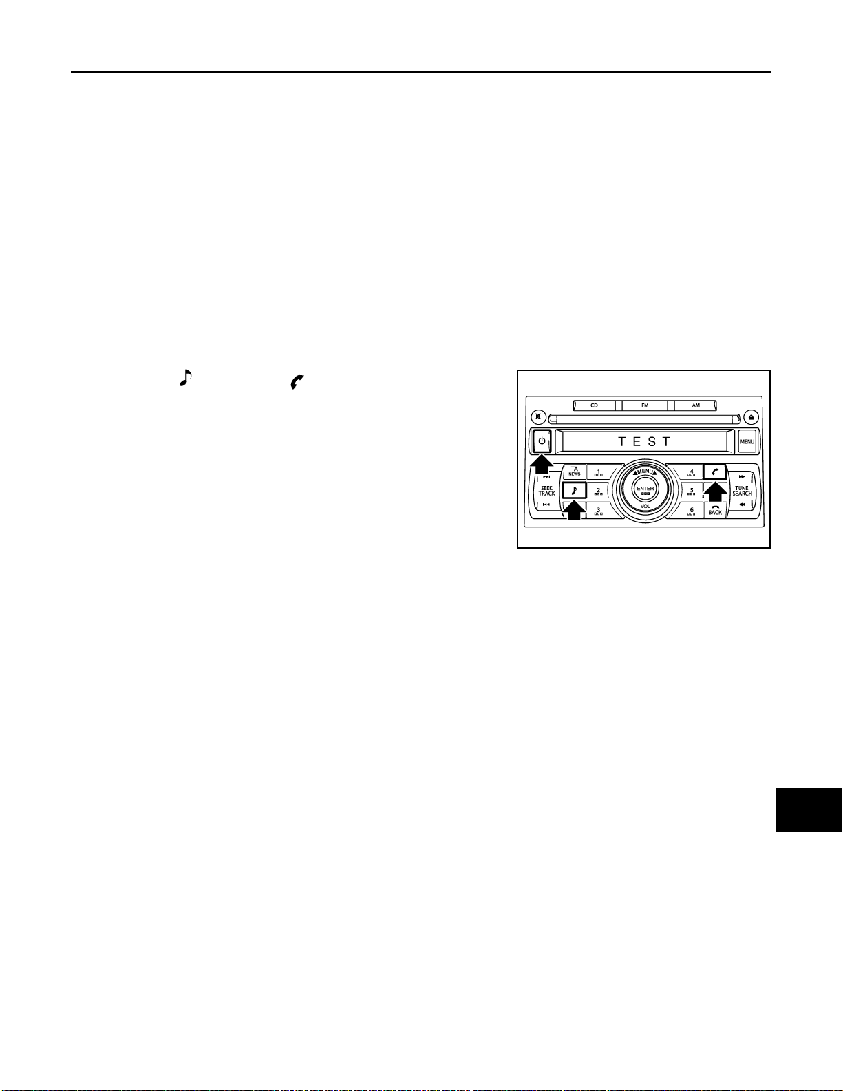
AUDIO UNIT ON BOARD DIAGNOSIS FUNCTION
Audio unit can perform a test for the microphone used for the hands-free phone system.
ON BOARD DIAGNOSIS
Description
• Speaker's voice is output from the speaker by speaking into the microphone in the microphone test mode.
This allows function validation of the microphone.
• If no voice can be output from the speaker for a microphone test even when audio functions other than
Hands-free Phone System are normal, check the microphone.
STARTING PROCEDURE
1. Start the engine.
2. Turn the audio system OFF.
3. With both “ ” button and “ ” button pressed, turn ON the
audio system.
4. Audio unit display shows “TEST”, and microphone test mode
starts.
5. Speak into the microphone to check functions of microphone.
6. Microphone test mode exits when the audio system is turned
OFF.
NOTE:
Volume can be adjusted during microphone tests.
JSNIA0422GB
A
B
C
D
E
F
G
H
I
AV
J
K
L
M
O
P
AV-11
Page 18
POWER SUPPLY AND GROUND CIRCUIT
< COMPONENT DIAGNOSIS >
[AUDIO WITHOUT NAVIGATION]
COMPONENT DIAGNOSIS
POWER SUPPLY AND GROUND CIRCUIT
AUDIO UNIT
AUDIO UNIT : Diagnosis Procedure INFOID:0000000001092897
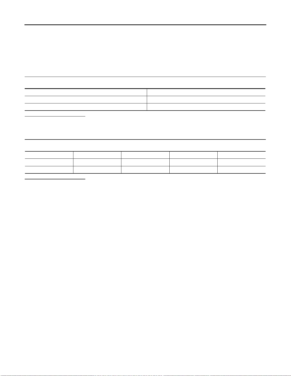
1.CHECK FUSE
Check for blown fuses.
Power source Fuse No.
Battery 35
Ignition switch ACC or ON 20
Is inspection result normal?
YES >> GO TO 2.
NO >> Be sure to eliminate cause of malfunction before installing new fuse.
2.CHECK POWER SUPPLY CIRCUIT
Check voltage between audio unit harness connectors and ground.
Signal name Connector No. Terminal No. Ignition switch position Value (Approx.)
Battery power supply M46 19 OFF 12 V
ACC power supply M46 7 ACC 12 V
Is inspection result normal?
YES >> INSPECTION END
NO >> Check harness between audio unit and fuse.
AV-12
Page 19
< COMPONENT DIAGNOSIS >
MICROPHONE SIGNAL CIRCUIT
[AUDIO WITHOUT NAVIGATION]
MICROPHONE SIGNAL CIRCUIT
Description INFOID:0000000001092898
Supply power from audio unit to microphone. The microphone transmits the sound voice to the audio unit.
Diagnosis Procedure INFOID:0000000001092899
1.CHECK CONTINUITY BETWEEN AUDIO UNIT AND MICROPHONE CIRCUIT
1. Turn ignition switch OFF.
2. Disconnect audio unit connector and microphone connector.
3. Check continuity between audio unit harness connector terminals 35, 36, 37 and microphone harness
connector terminals 1, 2, 4.
35 - 1 : Continuity should exist.
36 - 2 : Continuity should exist.
37 - 4 : Continuity should exist.
4. Check continuity between audio unit harness connector terminals 35, 37 and ground.
35, 37 - Ground : Continuity should not exist.
Is inspection result normal?
YES >> GO TO 2.
NO >> Repair harness or connector.
2.CHECK VOLTAGE MICROPHONE VCC
A
B
C
D
E
F
G
H
1. Connect audio unit connector.
2. Turn ignition switch ON.
3. Check voltage between audio unit harness connector terminal 37 and ground.
37 - ground : Approx. 5 V
Is inspection result normal?
YES >> GO TO 3.
NO >> Replace audio unit.
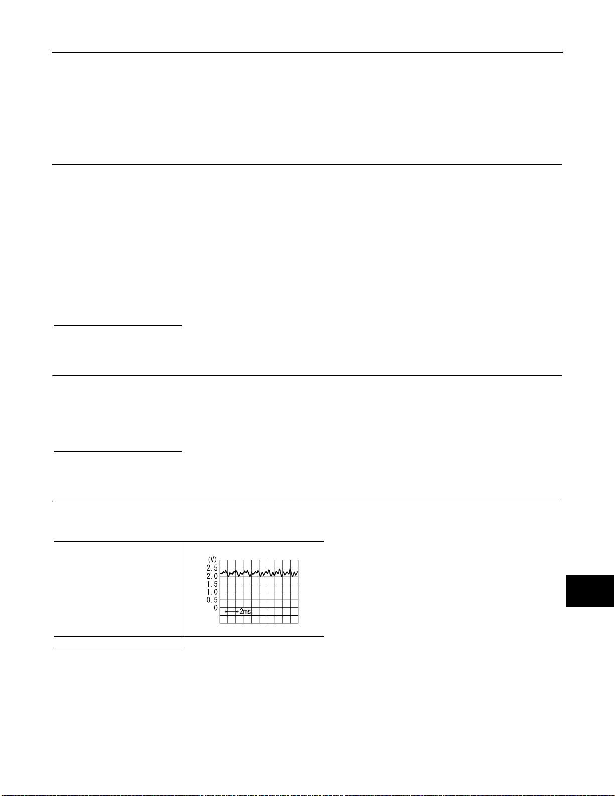
3.CHECK MICROPHONE SIGNAL
1. Connect microphone connector.
2. Check signal between audio unit harness connector terminals 35 and 36.
35 - 36
PKIB5037J
Is inspection result normal?
YES >> Replace audio unit.
NO >> Replace microphone.
I
J
K
L
M
AV
O
P
AV-13
Page 20

STEERING SWITCH SIGNAL A CIRCUIT
< COMPONENT DIAGNOSIS >
[AUDIO WITHOUT NAVIGATION]
STEERING SWITCH SIGNAL A CIRCUIT
Description INFOID:0000000001092900
Transmits the steering switch signal to audio unit.
Diagnosis Procedure INFOID:0000000001092901
1.CHECK STEERING SWITCH SIGNAL A CIRCUIT
1. Turn ignition switch OFF.
2. Disconnect audio unit connector and spiral cable connector.
3. Check continuity between audio unit harness connector terminal 6 and spiral cable harness connector terminal 24.
6 - 24 : Continuity should exist.
4. Check continuity between audio unit harness connector terminal 6 and ground.
6 - Ground : Continuity should not exist.
Is inspection result normal?
YES >> GO TO 2.
NO >> Repair harness or connector.
2.CHECK SPIRAL CABLE
Check spiral cable.
Is inspection result normal?
YES >> GO TO 3.
NO >> Replace spiral cable.
3.CHECK AUDIO UNIT VOLTAGE
1. Connect audio unit connector and spiral cable connector.
2. Turn ignition switch ON.
3. Check voltage between audio unit harness connector terminals 6 and 15.
6 - 15 : Approx. 5 V
Is inspection result normal?
YES >> GO TO 4.
NO >> Replace audio unit.
4.CHECK STEERING SWITCH
1. Turn ignition switch OFF.
2. Check steering switch. Refer to AV-14, "
Is inspection result normal?
YES >> INSPECTION END
NO >> Replace steering switch.
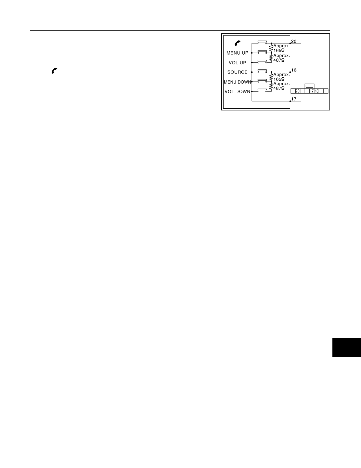
Component Inspection INFOID:0000000001092902
Component Inspection".
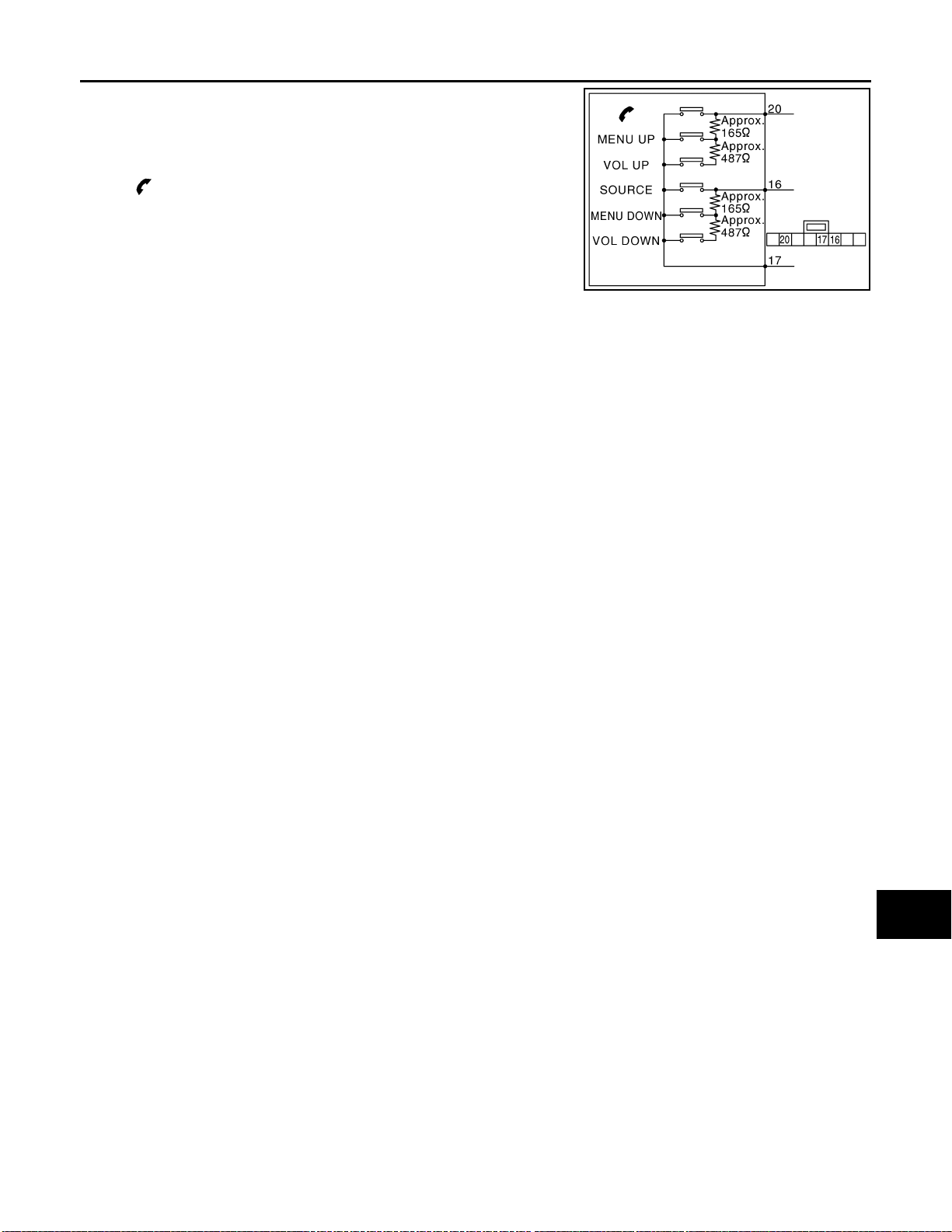
Measure the resistance between the steering switch connector terminals 20 to 17 and 16 to 17.
AV-14
Page 21
STEERING SWITCH SIGNAL A CIRCUIT
< COMPONENT DIAGNOSIS >
Standard
Between terminals 20 and 17
VOL UP switch ON : 634 – 665 Ω
MENU UP switch ON : 162 – 168 Ω
switch ON
: 0 Ω
[AUDIO WITHOUT NAVIGATION]
A
B
Between terminals 16 and 17
VOL DOWN switch ON : 634 – 665 Ω
MENU DOWN switch ON : 162 – 168 Ω
SOURCE switch ON : 0 Ω
C
JSNIA0396GB
D
E
F
G
H
I
J
AV
K
L
M
O
P
AV-15
Page 22

STEERING SWITCH SIGNAL B CIRCUIT
< COMPONENT DIAGNOSIS >
[AUDIO WITHOUT NAVIGATION]
STEERING SWITCH SIGNAL B CIRCUIT
Description INFOID:0000000001117158
Transmits the steering switch signal to audio unit.
Diagnosis Procedure INFOID:0000000001092904
1.CHECK STEERING SWITCH SIGNAL B CIRCUIT
1. Turn ignition switch OFF.
2. Disconnect audio unit connector and spiral cable connector.
3. Check continuity between audio unit harness connector terminal 16 and spiral cable harness connector
terminal 32.
16 - 32 : Continuity should exist.
4. Check continuity between audio unit harness connector terminal 16 and ground.
16 - Ground : Continuity should not exist.
Is inspection result normal?
YES >> GO TO 2.
NO >> Repair harness or connector.
2.CHECK SPIRAL CABLE
Check spiral cable.
Is inspection result normal?
YES >> GO TO 3.
NO >> Replace spiral cable.
3.CHECK AUDIO UNIT VOLTAGE
1. Connect audio unit connector and spiral cable connector.
2. Turn ignition switch ON.
3. Check voltage between audio unit harness connector terminals 16 and 15.
16 - 15 : Approx. 5 V
Is inspection result normal?
YES >> GO TO 4.
NO >> Replace audio unit.
4.CHECK STEERING SWITCH
1. Turn ignition switch OFF.
2. Check steering switch. Refer to AV-16, "
Is inspection result normal?
YES >> INSPECTION END
NO >> Replace steering switch.
Component Inspection INFOID:0000000001117160
Component Inspection".
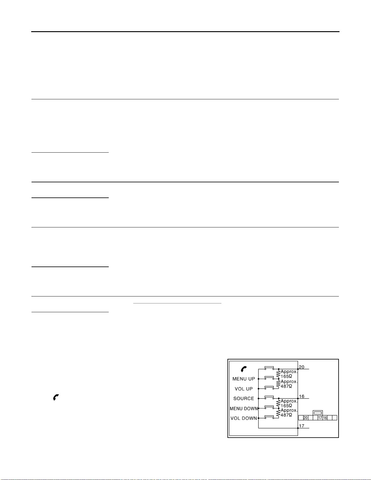
Measure the resistance between the steering switch connector terminals 20 to 17 and 16 to 17.
AV-16
Page 23
STEERING SWITCH SIGNAL B CIRCUIT
< COMPONENT DIAGNOSIS >
Standard
Between terminals 20 and 17
VOL UP switch ON : 634 – 665 Ω
MENU UP switch ON : 162 – 168 Ω
switch ON
: 0 Ω
[AUDIO WITHOUT NAVIGATION]
A
B
Between terminals 16 and 17
VOL DOWN switch ON : 634 – 665 Ω
MENU DOWN switch ON : 162 – 168 Ω
SOURCE switch ON : 0 Ω
C
JSNIA0396GB
D
E
F
G
H
I
J
AV
K
L
M
O
P
AV-17
Page 24
STEERING SWITCH SIGNAL GND CIRCUIT
< COMPONENT DIAGNOSIS >
[AUDIO WITHOUT NAVIGATION]
STEERING SWITCH SIGNAL GND CIRCUIT
Description INFOID:0000000001117159
Transmits the steering switch signal to audio unit.
Diagnosis Procedure INFOID:0000000001092907
1.CHECK STEERING SWITCH SIGNAL GND CIRCUIT
1. Turn ignition switch OFF.
2. Disconnect audio unit connector and spiral cable connector.
3. Check continuity between audio unit harness connector terminal 15 and spiral cable harness connector
terminal 31.
15 - 31 : Continuity should exist.
Is inspection result normal?
YES >> GO TO 2.
NO >> Repair harness or connector.
2.CHECK SPIRAL CABLE
Check spiral cable.
Is inspection result normal?
YES >> GO TO 3.
NO >> Replace spiral cable.
3.CHECK GROUND CIRCUIT
1. Connect audio unit connector.
2. Check continuity between audio unit harness connector terminal 15 and ground.
15 - Ground : Continuity should exist.
Is inspection result normal?
YES >> GO TO 4.
NO >> Replace audio unit.
4.CHECK STEERING SWITCH
1. Check steering switch. Refer to AV-18, "
Is inspection result normal?
YES >> INSPECTION END
NO >> Replace steering switch.
Component Inspection INFOID:0000000001117161
Measure the resistance between the steering switch connector terminals 20 to 17 and 16 to 17.
Standard
Between terminals 20 and 17
VOL UP switch ON : 634 – 665 Ω
MENU UP switch ON : 162 – 168 Ω
switch ON
Component Inspection".
: 0 Ω
Between terminals 16 and 17
VOL DOWN switch ON : 634 – 665 Ω
MENU DOWN switch ON : 162 – 168 Ω
SOURCE switch ON : 0 Ω
AV-18
JSNIA0396GB
Page 25
< ECU DIAGNOSIS >
AUDIO UNIT
[AUDIO WITHOUT NAVIGATION]
ECU DIAGNOSIS
AUDIO UNIT
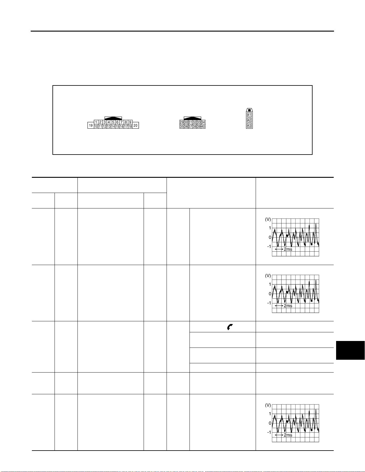
Reference Value INFOID:0000000001092909
TERMINAL LAYOUT
JPNIA0230ZZ
PHYSICAL VALUES
Terminal
(Wire color)
+ – Signal name
Description
Input/
Output
Condition
Reference value
(Approx.)
A
B
C
D
E
F
G
H
2
(W)
4
(LG)
6*
(V)
7
(SB)
3
Sound signal front LH Output
(P)
5
Sound signal rear LH Output
(R)
15*
(GR)
Ground ACC power supply Input
Steering switch signal A Input
Ignition
switch ONVoice output
Ignition
switch ONVoice output
Keep pressing switch.
Ignition
switch
Ignition
switch
ACC
Keep pressing MENU UP
switch.
Keep pressing VOL UP
ON
switch.
Except for above. 5 V
0 V
1.7 V
3.3 V
− Battery voltage
SKIB3609E
SKIB3609E
I
J
K
L
M
AV
O
P
11
(G)
12
Sound signal front RH Output
(R)
Ignition
switch ONVoice output
SKIB3609E
AV-19
Page 26

< ECU DIAGNOSIS >
AUDIO UNIT
[AUDIO WITHOUT NAVIGATION]
Terminal
(Wire color)
+ – Signal name
13
(BR)
15*
(GR)
16*
(O)
17
(B)
14
Sound signal rear RH Output
(Y)
Ground Steering switch signal GND —
15*
(GR)
Steering switch signal B Input
— Immobilizer — — — —
Description
Input/
Output
Condition
Ignition
switch ONVoice output
Ignition
switch
ON
Keep pressing SOURCE
switch.
Ignition
switch
ON
Keep pressing MENU
DOWN switch.
Keep pressing VOL DOWN
switch.
Except for above. 5 V
Reference value
(Approx.)
SKIB3609E
—0 V
0 V
1.7 V
3.3 V
18
Ground
(V)
19
(BR)
35*
(G)
36* Ground Mic. GND —
37*
(R)
*: With hands-free phone system
Ground Battery power supply Input
32
Ground Control signal —
(B)
41 Ground Antenna amp. ON signal Output
42 — Antenna signal Input — — —
Vehicle speed signal (8pulse)
36* Microphone signal Input
36* Microphone VCC Output
Input
Ignition
switch
ON
Ignition
switch
OFF
Ignition
switch
ON
Ignition
switch ONSounds
Ignition
switch
ON
Ignition
switch
ON
Ignition
switch
ACC
When vehicle speed is approx. 40 km/h (25MPH)
— Battery voltage
—0 V
—0 V
—5 V
—12 V
SKIA6649J
PKIB5037J
AV-20
Page 27
AUDIO UNIT
B
< ECU DIAGNOSIS >
[AUDIO WITHOUT NAVIGATION]
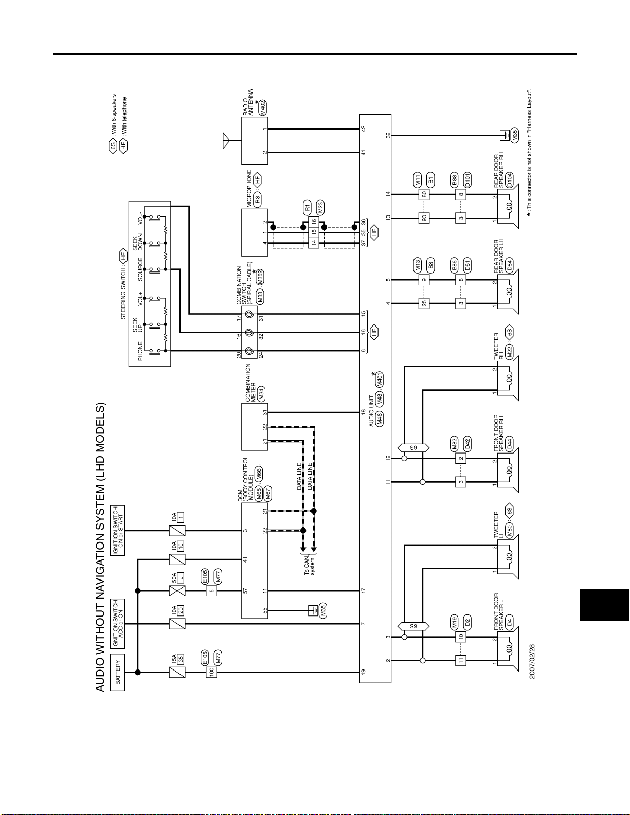
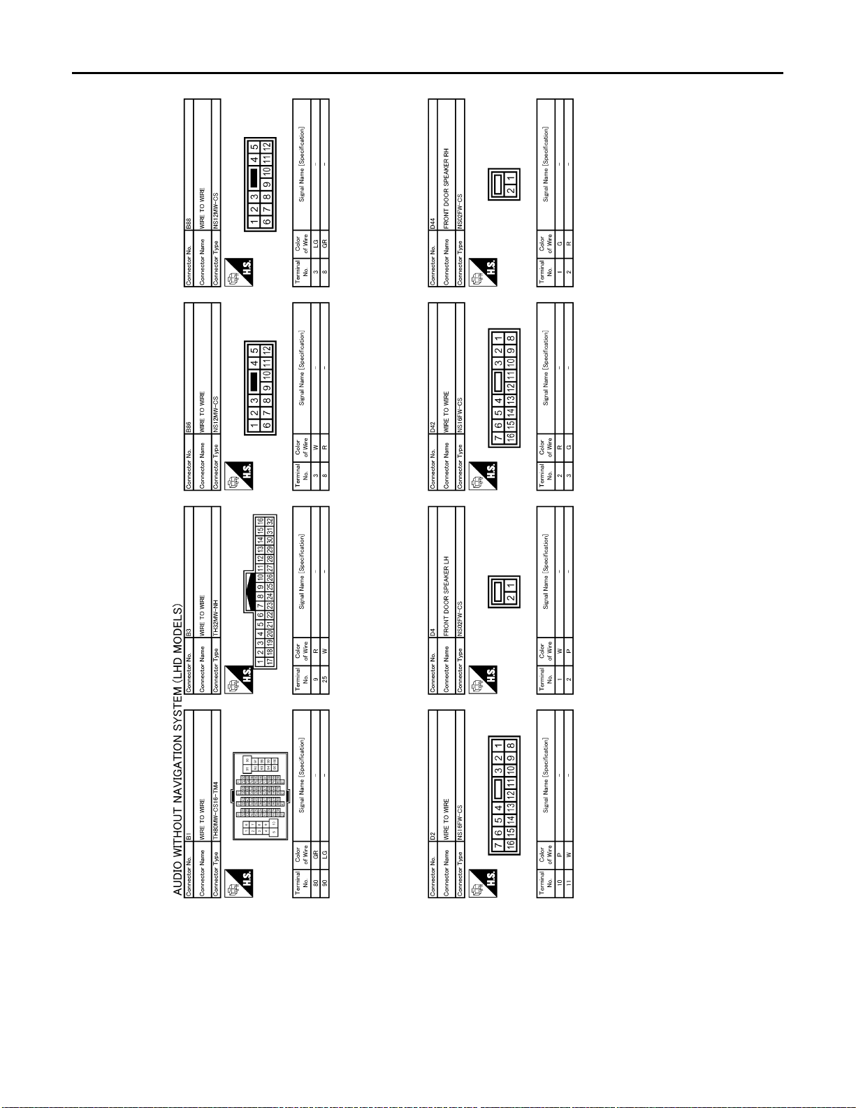
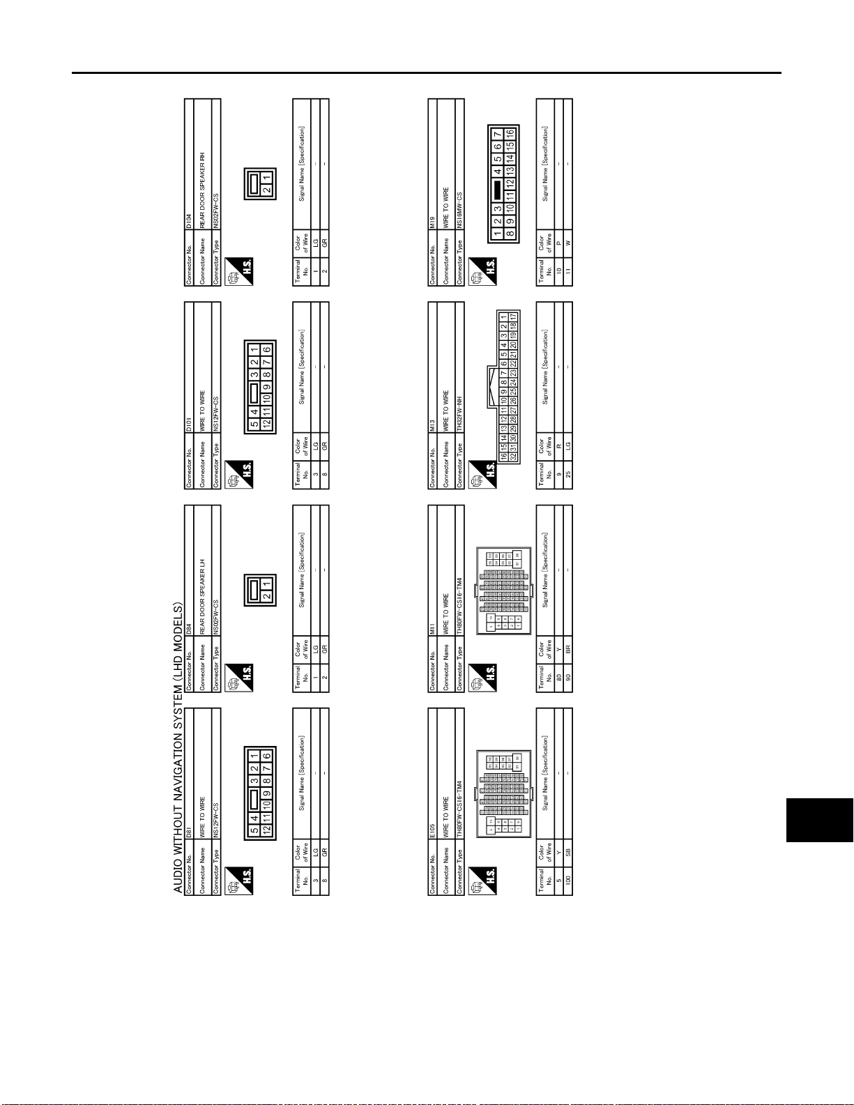
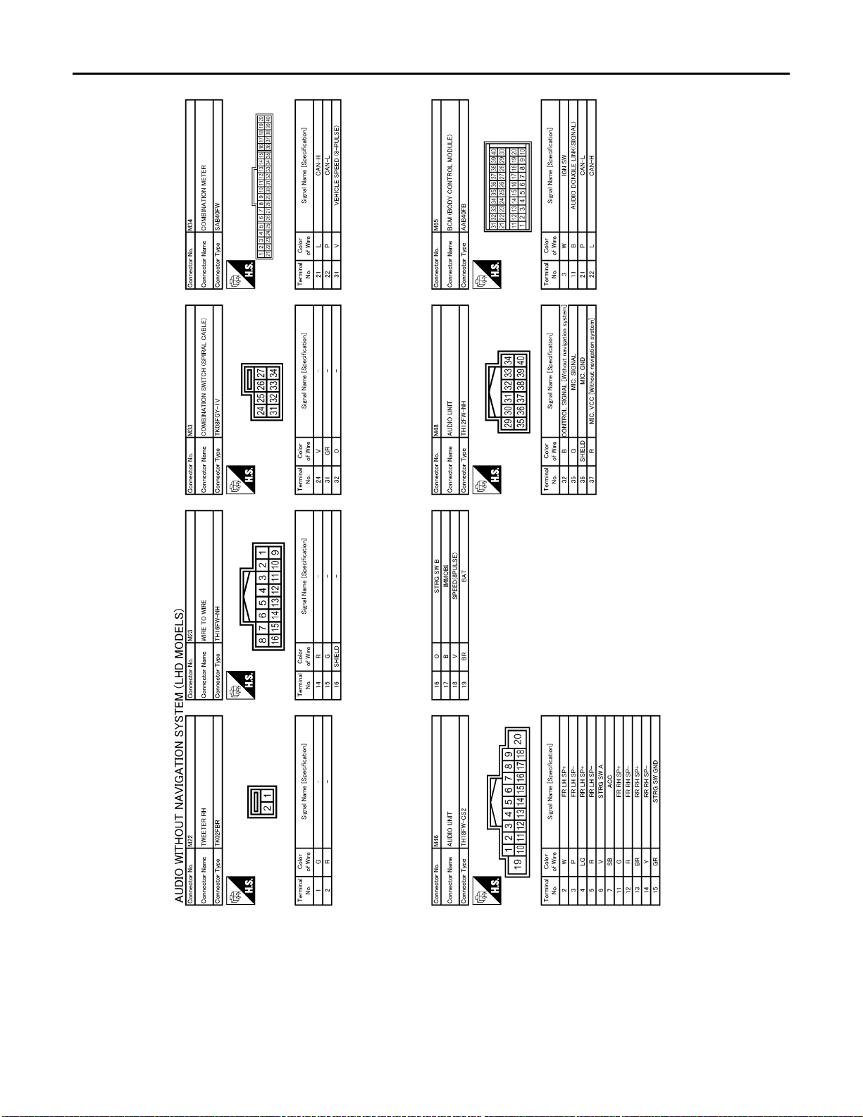
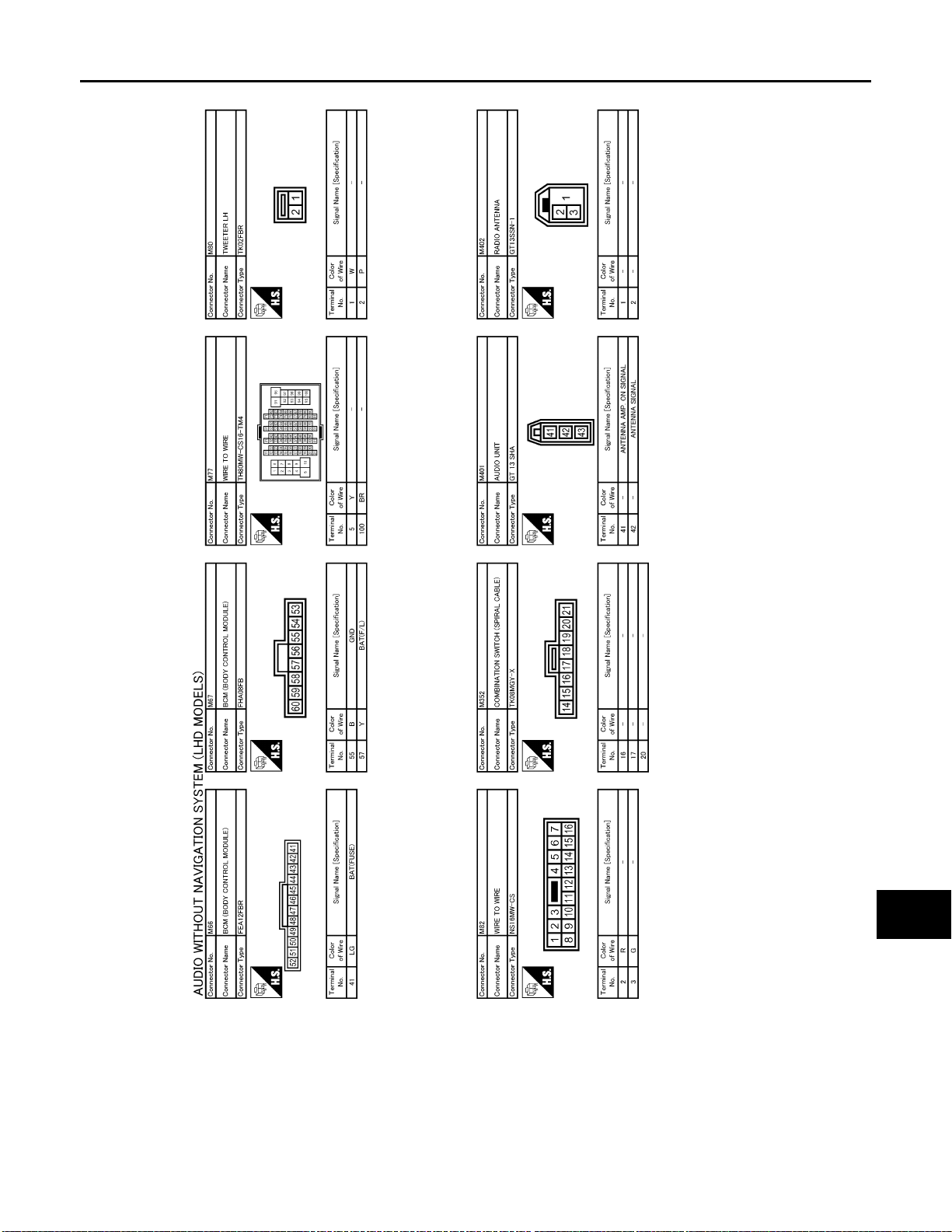
Wiring Diagram—AUDIO WITHOUT NAVIGATION SYSTEM (LHD MODELS)—
INFOID:0000000001092910
A
B
C
D
E
F
G
AV
H
I
J
K
L
M
O
AV-21
JCNWA0283G
P
Page 28
< ECU DIAGNOSIS >
B
AUDIO UNIT
[AUDIO WITHOUT NAVIGATION]
AV-22
JCNWA0284G
Page 29
< ECU DIAGNOSIS >
B
AUDIO UNIT
[AUDIO WITHOUT NAVIGATION]
A
B
C
D
E
F
G
AV
H
I
J
K
L
M
O
AV-23
JCNWA0285G
P
Page 30
< ECU DIAGNOSIS >
B
AUDIO UNIT
[AUDIO WITHOUT NAVIGATION]
AV-24
JCNWA0286G
Page 31
< ECU DIAGNOSIS >
B
AUDIO UNIT
[AUDIO WITHOUT NAVIGATION]
A
B
C
D
E
F
G
AV
H
I
J
K
L
M
O
AV-25
JCNWA0287G
P
Page 32
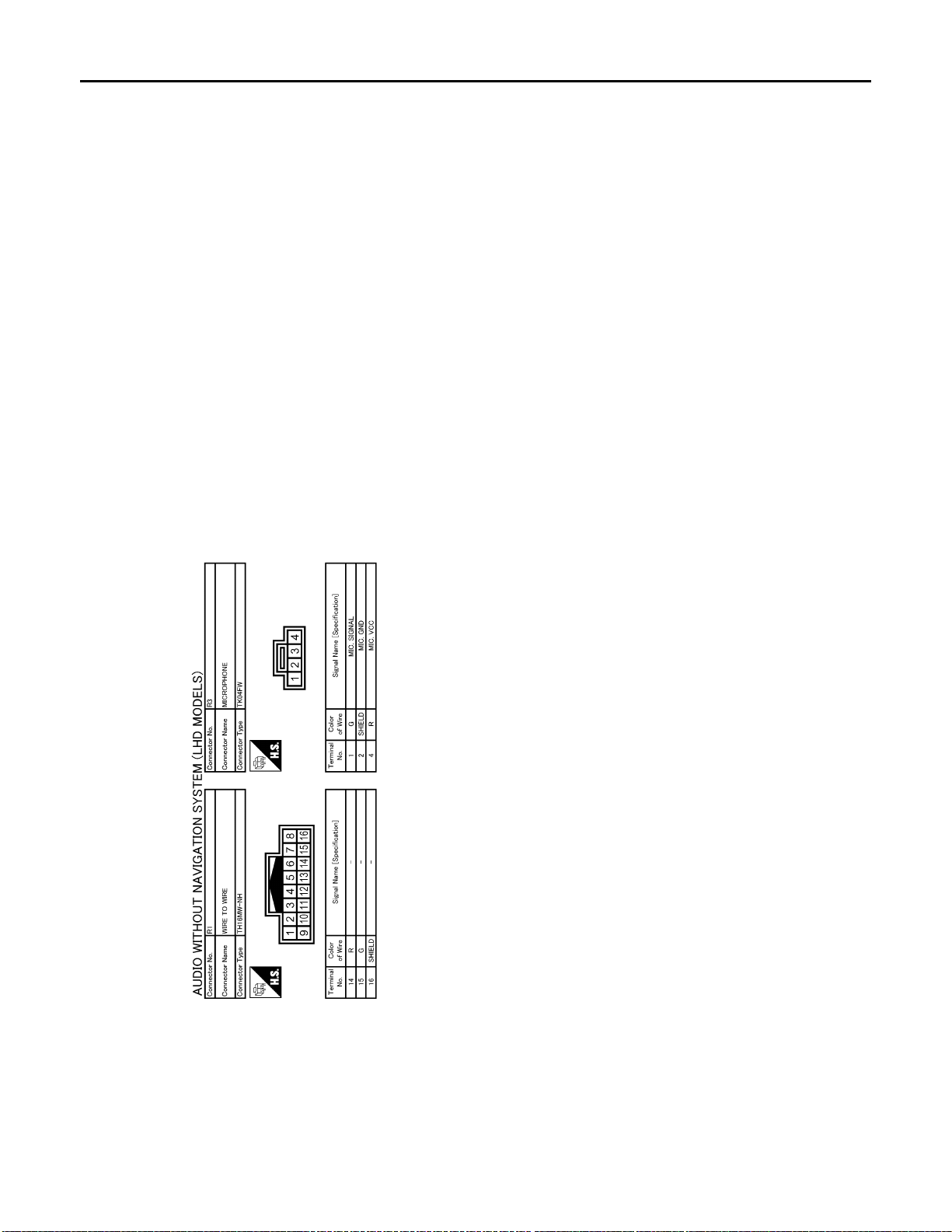
< ECU DIAGNOSIS >
B
AUDIO UNIT
[AUDIO WITHOUT NAVIGATION]
AV-26
JCNWA0288G
Page 33
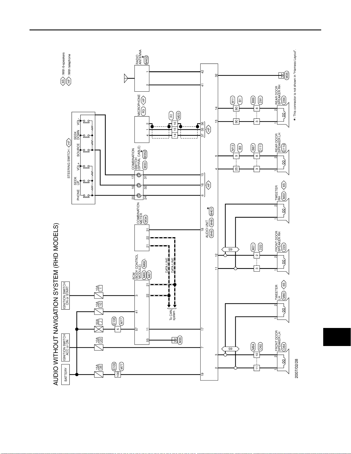
AUDIO UNIT
B
< ECU DIAGNOSIS >
[AUDIO WITHOUT NAVIGATION]
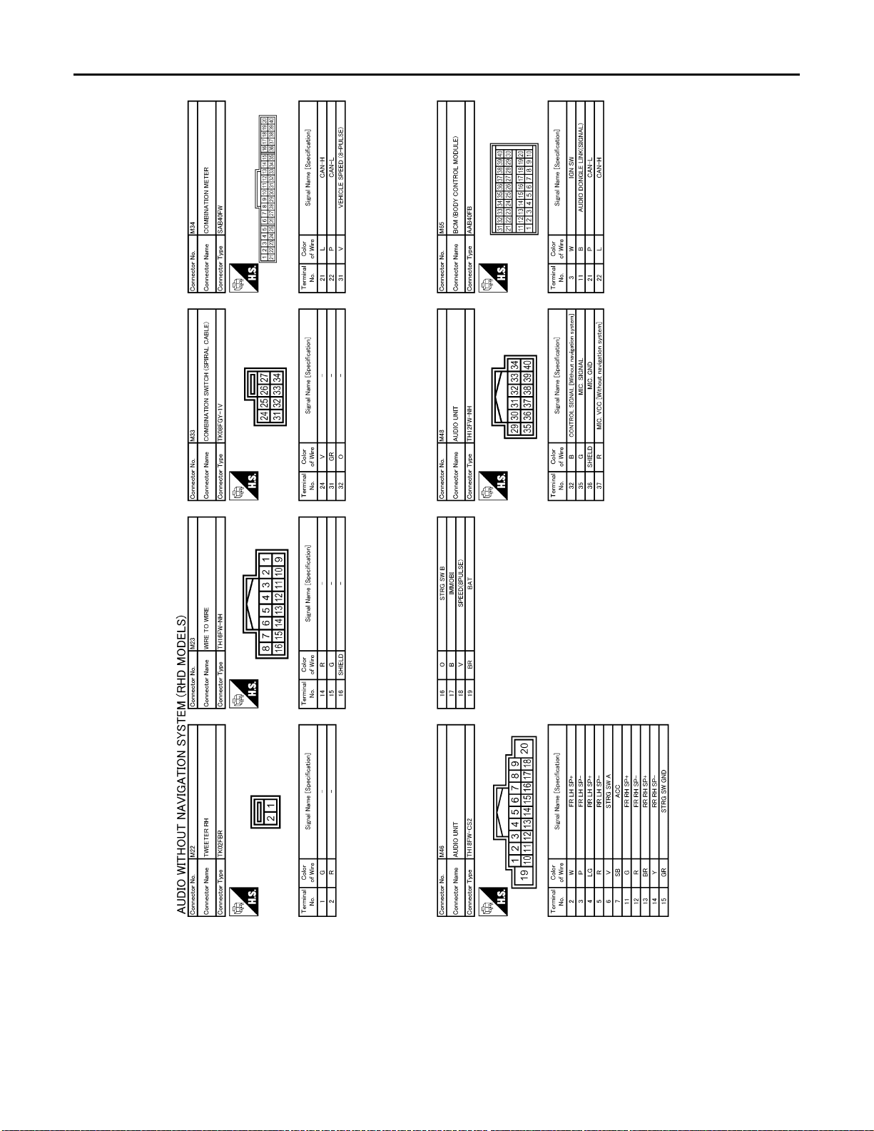
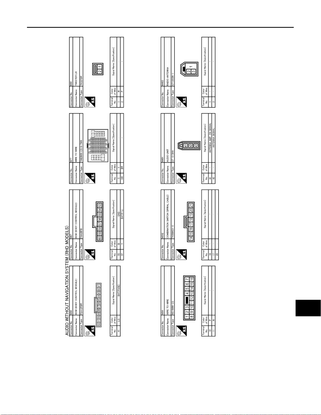
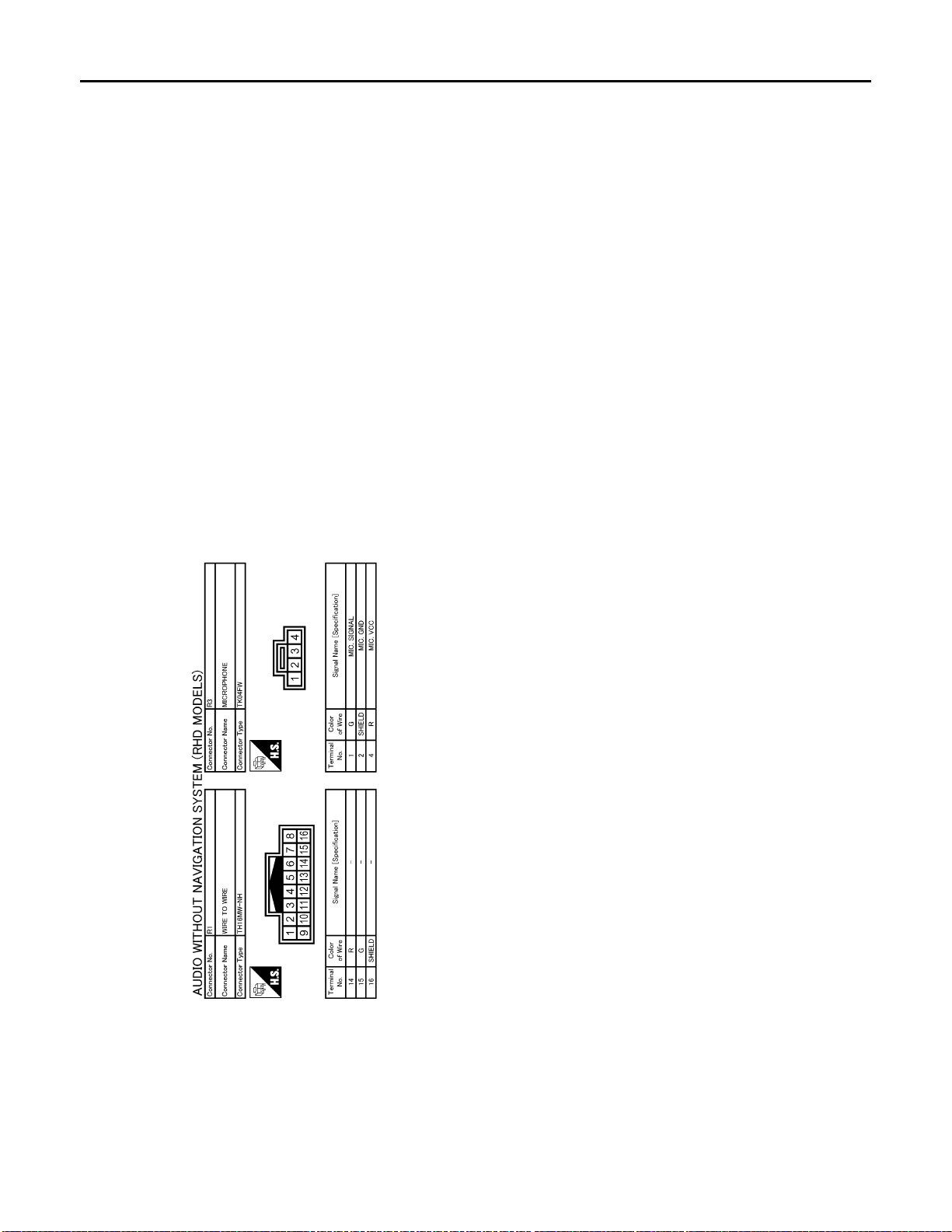
Wiring Diagram—AUDIO WITHOUT NAVIGATION SYSTEM (RHD MODELS)—
INFOID:0000000001537472
A
B
C
D
E
F
G
AV
H
I
J
K
L
M
O
AV-27
JCNWA0289G
P
Page 34
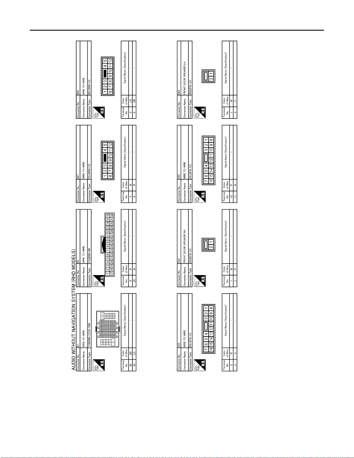
< ECU DIAGNOSIS >
B
AUDIO UNIT
[AUDIO WITHOUT NAVIGATION]
AV-28
JCNWA0290G
Page 35
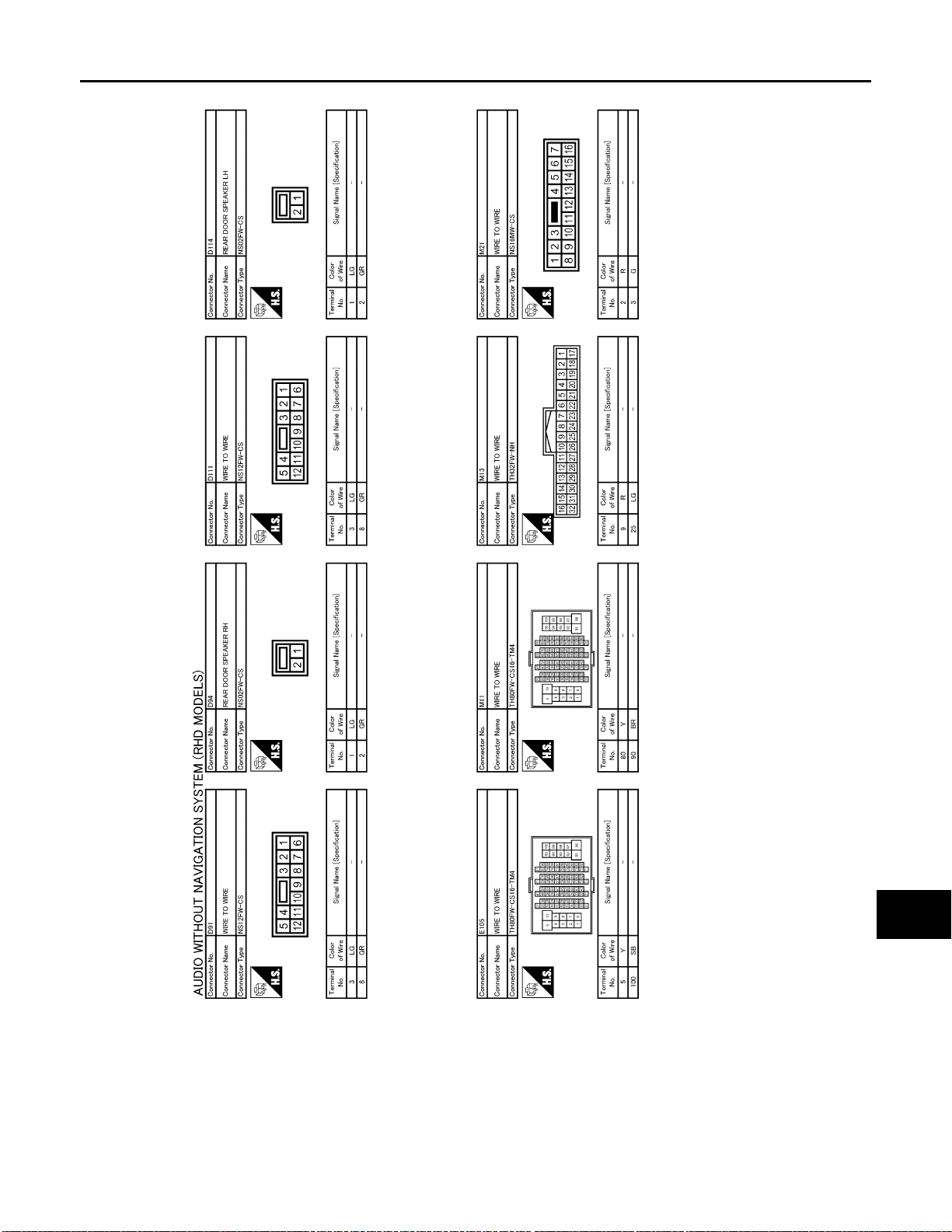
< ECU DIAGNOSIS >
B
AUDIO UNIT
[AUDIO WITHOUT NAVIGATION]
A
B
C
D
E
F
G
AV
H
I
J
K
L
M
O
AV-29
JCNWA0291G
P
Page 36
< ECU DIAGNOSIS >
B
AUDIO UNIT
[AUDIO WITHOUT NAVIGATION]
AV-30
JCNWA0292G
Page 37
< ECU DIAGNOSIS >
B
AUDIO UNIT
[AUDIO WITHOUT NAVIGATION]
A
B
C
D
E
F
G
AV
H
I
J
K
L
M
O
AV-31
JCNWA0293G
P
Page 38
< ECU DIAGNOSIS >
B
AUDIO UNIT
[AUDIO WITHOUT NAVIGATION]
AV-32
JCNWA0294G
Page 39
< SYMPTOM DIAGNOSIS >
MULTI AV SYSTEM SYMPTOMS
[AUDIO WITHOUT NAVIGATION]
SYMPTOM DIAGNOSIS
MULTI AV SYSTEM SYMPTOMS
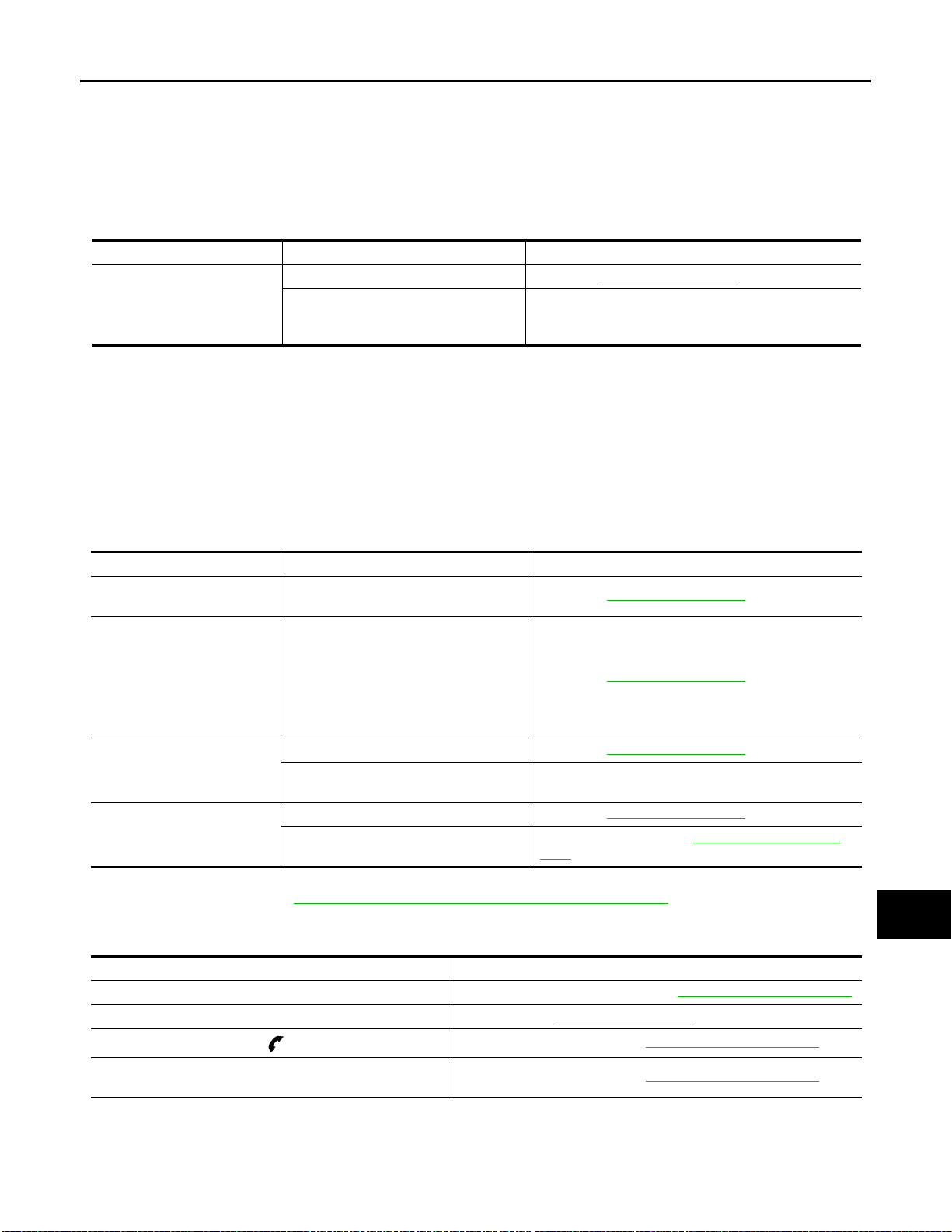
Symptom Table INFOID:0000000001092911
RELATED TO AUDIO
Symptom Check items Possible malfunction location / Action to take
No sound from all speakers Audio unit (AV-37, "
Audio sound is not heard.
Sound is not heard only from the specific places (front RH, rear RH, front LH
and rear LH).
Sound signal circuit of suspect system
RELATED TO HANDS-FREE PHONE (WITH HANDS-FREE PHONE SYSTEM)
• Check that the cellular phone is corresponding type (Bluetooth® enabled) when the hands free related malfunction vehicle is in service before performing a diagnosis.
• There is a case that malfunction occurs due to the version change of the phone type, etc. even though it is a
corresponding type. Therefore, confirm it by changing the cellular phone to another corresponding type
phone, and check that it operates normally. It is necessary to distinguish whether the cause is the vehicle or
cellular phone. Check to ensure the customer's phone is supported by checking the phone compatibility for
the hands free system.
Trouble diagnosis chart by symptom
Symptoms Check items Possible malfunction location / Action to take
Does not recognize cellular
phone connection.
Hands-free phone cannot be
activated.
The other party's voice cannot
be heard by hands-free phone.
Originating sound is not heard
by the other party with handsfree phone communication.
NOTE:
Regarding microphone test, refer to AV-11, "
Repeat the registration of cellular phone. Audio unit (AV-37, "Exploded View")
• Hands-free phone operation can be
made, but the communicati on cannot
be established.
• Hands-free phone operation can be
performed, however, voice between
each other cannot be heard during the
conversation.
No sound from all speakers Audio unit (AV-37, "Exploded View")
Sound is not heard only f rom the sp ecific
places (front RH or front LH).
Microphone test is normal. Audio unit (AV-37, "
A microphone is not usable on a micro-
phone test.
Diagnosis Description (With Hands-free Phone System)".
Audio unit (AV-37, "
Sound signal circuit (TEL voice)
Microphone signal circuit (AV-13, "
dure")
RELATED TO STEERING SWITCH (WITH HANDS-FREE PHONE SYSTEM)
Exploded View")
Exploded View")
Exploded View")
Diagnosis Proce-
A
B
C
D
E
F
G
H
I
J
K
L
M
AV
Symptoms Possible malfunction location / Action to take
All steering switches are not operated. Steering switch signal ground circuit (AV-18, "
Only specified switch cannot be operated. Steering switch (AV-41, "Exploded View")
“MENU UP”, “VOL UP” and “ ” switches are not operated.
“SOURCE”, “MENU DOWN” and “VOL DOWN” switches are
not operated.
Steering switch signal A circuit (AV-14, "
Steering switch signal B circuit (AV-16, "
Diagnosis Procedure")
Diagnosis Procedure")
AV-33
Diagnosis Procedure")
O
P
Page 40

NORMAL OPERATING CONDITION
< SYMPTOM DIAGNOSIS >
[AUDIO WITHOUT NAVIGATION]
NORMAL OPERATING CONDITION
Description INFOID:0000000001092912
RELATED TO AUDIO
• The majority of the audio malfunctions are the result of outside causes (bad CD, electromagnetic interference, etc.). Check the symptoms below to diagnose the malfunction.
• The vehicle itself can be a source of noise if noise prevention parts or electrical equipment is malfunctioning.
Check that noise is caused and/or changed by engine speed, ignition switch turned to each position, and
operation of each piece of electrical equipment. Then determine the cause.
NOTE:
• CD-R is not guaranteed to play because they can contain compressed audio (MP3, WMA) or could be incorrectly mastered by the customer on a computer.
• Check that the CDs carry the Compact Disc Logo. If not, the disc is not mastered to the red book Compact
Disc Standard and may not play.
Symptoms Cause and counter measure
Check that the CD was inserted correctly.
Check that the CD is scratched or dirty.
Check that there is condensation inside the player, and if there is, wait until the condensation is
gone (about 1 hour) before using the player.
Cannot play
Poor sound quality Check that the CD is scratched or dirty.
It takes a relatively long time before
the music starts playing.
The songs do not play back in the
desired order.
Noise resulting from variations in field streng th, such as fading noise and multi-path noise, or external noise from trains and other
sources, is not a malfunction.
NOTE:
• Fading noise: This noise occurs because of variations in the field streng th in a narrow range due to mountains or buildi ngs blocking
the signal.
• Multi-path noise: This noise results from a time difference between the broadcast waves directly from the station arriving at the
antenna and the waves reflected by mountains or buildin gs.
The player will play correctly after it returns to the normal temperature if there is a temperature
increase error.
Only the music CD files (CD-DA data) will be played if there is a mixture of music CD files (CDDA data) and MP3/WMA files on a CD.
Files with extensions other than “.MP3”, “.WMA”, “.mp3”, or “.wma” cannot be played.
Check that the finalization process, such as session close and disc close, is done for the disc.
Check that the CD is protected by copyright.
If there are many folder or file levels on the MP3/WMA CD, or if it is a multisession disc, some
time may be required before the music starts playing.
The playback order is the order in which th e fil es w ere writ te n by th e so ftware, so the files might
not play in the desired order.
RELATED TO TELEPHONE (WITH HANDS-FREE PHONE SYSTEM)
Symptoms Cause and counter measure
Intermittent voice turbulence occurs between buildings.
Noise interference occurs under the railroad overpass or near high-tension wires,
traffic lights, or neon signs.
Booming noises are mixed into audio. Radio waves from the cell phone may be mixed into audio.
No sound can be heard:
• Voice from the party on the other end of
the line cannot be heard.
• No ring tone.
Surrounded by buildings, cell phones may have a poor reception due to radio waves
irregular reflection or interception.
Noise waves from these may be mixed into radio waves.
• Check that the key switch is not set to ON or ACC.
• Check that sound volume (VOL) is not set to minimum.
• Check that the connection of Bluetooth
• Adjust cell phone ring tone and volume. Volume levels of ring tone and voice on the
phone depend on the volume setting of the cell phone, according to the model.
®
is normal.
AV-34
Page 41

< SYMPTOM DIAGNOSIS >
NORMAL OPERATING CONDITION
[AUDIO WITHOUT NAVIGATION]
Symptoms Cause and counter measure
Voice ca nnot be transm itted to the p arty on
the other end of the line.
Telephone call does not get through.
The party on the othe r end of the line h ears
noises while talking on a hand-held cell
phone.
Bluetooth
nition switch ON.
Sound level of voice is different from that of
ringing sounds or ring tone.
The number of electric field rece ption bars
of the audio unit is different from that of the
cell phone. Or telephone call does not get
through even when transmitting with the reception bar displayed.
The party on the othe r end of the line h ears
muffled sounds while talking on the phone.
®
has a slow connection after ig-
®
Check that the connection of Bluetooth
• Check th at the cell phone is not locked.
• Check th at the connection of Bluetoot h
• Check that the telephone call is made in the area within the telecommunications carrier service area.
• Check that the area is not a blind area.
The party on the other end of the line may hear noises depending on where the cell
phone is placed.
Some models take time for standby.
This model allows separate settings for sound levels of ringing sounds, ring tone, and
voice.
Specifications regarding the number of electric field reception bars differ from cell
phone to cell phone. (Reception bar of the audio unit is the guideline.)
Ambient sounds through the micr ophone make muffled soun ds after conversion peculiar to digital devices.
is normal.
®
is normal.
A
B
C
D
E
F
G
H
AV
I
J
K
L
M
O
P
AV-35
Page 42

PRECAUTIONS
< PRECAUTION >
[AUDIO WITHOUT NAVIGATION]
PRECAUTION
PRECAUTIONS
Precaution for Supplemental Restraint System (SRS) "AIR BAG" and "SEAT BELT
PRE-TENSIONER" INFOID:0000000001312060
The Supplemental Restraint System such as “AIR BAG” and “SEAT BELT PRE-TENSIONER”, used along
with a front seat belt, helps to reduce the risk or severity of injury to the driver and front passenger for certain
types of collision. Information necessary to service the system safely is included in the “SRS AIRBAG” and
“SEAT BELT” of this Service Manual.
WARNING:
• To avoid rendering the SRS inoperative, which could increase the risk of personal injury or death in
the event of a collision which would result in air bag inflation, all maintenance must be performed by
an authorized NISSAN/INFINITI dealer.
• Improper maintenance, including incorrect removal and installation of the SRS, can lead to personal
injury caused by unintentional activation of the system. For removal of Spiral Cable and Air Bag
Module, see the “SRS AIRBAG”.
• Do not use electrical test equipment on any circuit related to the SRS unless instructed to in this
Service Manual. SRS wiring harnesses can be identified by yellow and/or orange harnesses or harness connectors.
AV-36
Page 43
< ON-VEHICLE REPAIR >
AUDIO UNIT
[AUDIO WITHOUT NAVIGATION]
ON-VEHICLE REPAIR
AUDIO UNIT
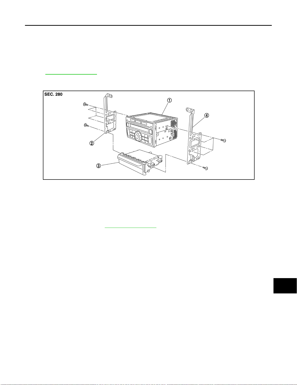
Exploded View INFOID:0000000001092914
REMOVAL
Refer to IP-11, "Exploded View".
DISASSEMBLY
JPNIA0319ZZ
A
B
C
D
E
F
G
H
1. Audio unit 2. Bracket LH 3. Pocket deck
4. Bracket RH
Removal and Installation INFOID:0000000001092915
REMOVAL
1. Remove cluster lid C. Refer to IP-11, "Exploded View".
2. Remove audio unit with a pocket deck as a single unit from the body.
3. Remove bracket screws, and then remove audio unit.
INSTALLATION
Install in the reverse order of removal.
I
J
K
L
M
AV
O
P
AV-37
Page 44
FRONT DOOR SPEAKER
< ON-VEHICLE REPAIR >
[AUDIO WITHOUT NAVIGATION]
FRONT DOOR SPEAKER
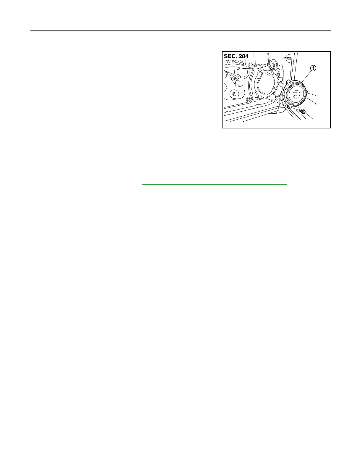
Exploded View INFOID:0000000001092916
JPNIA0321ZZ
1. Front door speaker
Removal and Installation INFOID:0000000001092917
REMOVAL
1. Remove front door finisher. Refer to INT-10, "FRONT DOOR FINISHER : Exploded View".
2. Remove front door speaker.
INSTALLATION
Install in the reverse order of removal.
AV-38
Page 45
< ON-VEHICLE REPAIR >
REAR DOOR SPEAKER
[AUDIO WITHOUT NAVIGATION]
REAR DOOR SPEAKER
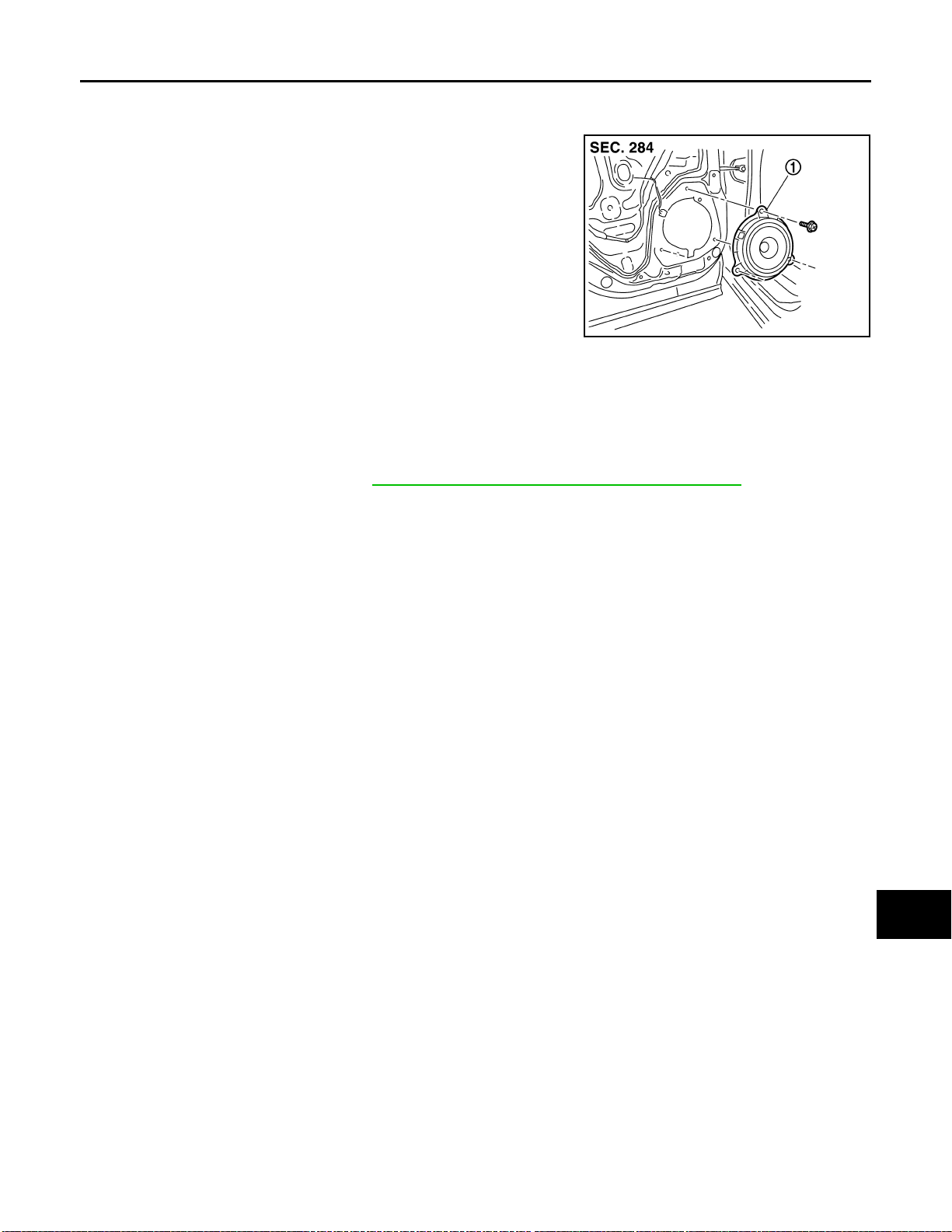
Exploded View INFOID:0000000001092918
JPNIA0322ZZ
1. Rear door speaker
Removal and Installation INFOID:0000000001092919
REMOVAL
1. Remove rear door finisher. Refer to INT-13, "REAR DOOR FINISHER : Exploded View".
2. Remove rear door speaker.
INSTALLATION
Install in the reverse order of removal.
A
B
C
D
E
F
G
H
AV
I
J
K
L
M
O
P
AV-39
Page 46
TWEETER
< ON-VEHICLE REPAIR >
[AUDIO WITHOUT NAVIGATION]
TWEETER
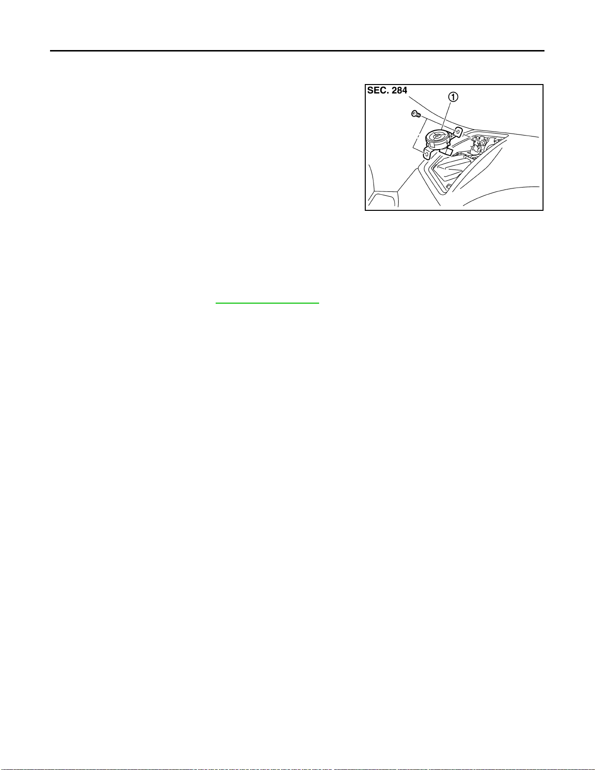
Exploded View INFOID:0000000001092920
JPNIA0323ZZ
1. Tweeter
Removal and Installation INFOID:0000000001092921
REMOVAL
1. Remove speaker grille. Refer to IP-11, "Exploded V iew".
2. Remove tweeter.
INSTALLATION
Install in the reverse order of removal.
AV-40
Page 47

< ON-VEHICLE REPAIR >
STEERING SWITCH
[AUDIO WITHOUT NAVIGATION]
STEERING SWITCH
Exploded View INFOID:0000000001092922
Refer to SR-5, "Exploded View".
Removal and Installation INFOID:0000000001092923
REMOVAL
Refer to SR-5, "Removal and Installation".
INSTALLATION
Install in the reverse order of removal.
A
B
C
D
E
F
G
H
AV
I
J
K
L
M
O
P
AV-41
Page 48
MICROPHONE
< ON-VEHICLE REPAIR >
[AUDIO WITHOUT NAVIGATION]
MICROPHONE
Exploded View INFOID:0000000001092924
REMOVAL
Refer to INT-22, "NORMAL ROOF : Exploded View" (Normal roof), INT-25, "SUNROOF : Exploded View"
(Sunroof).
DISASSEMBLY
JPNIA0324ZZ
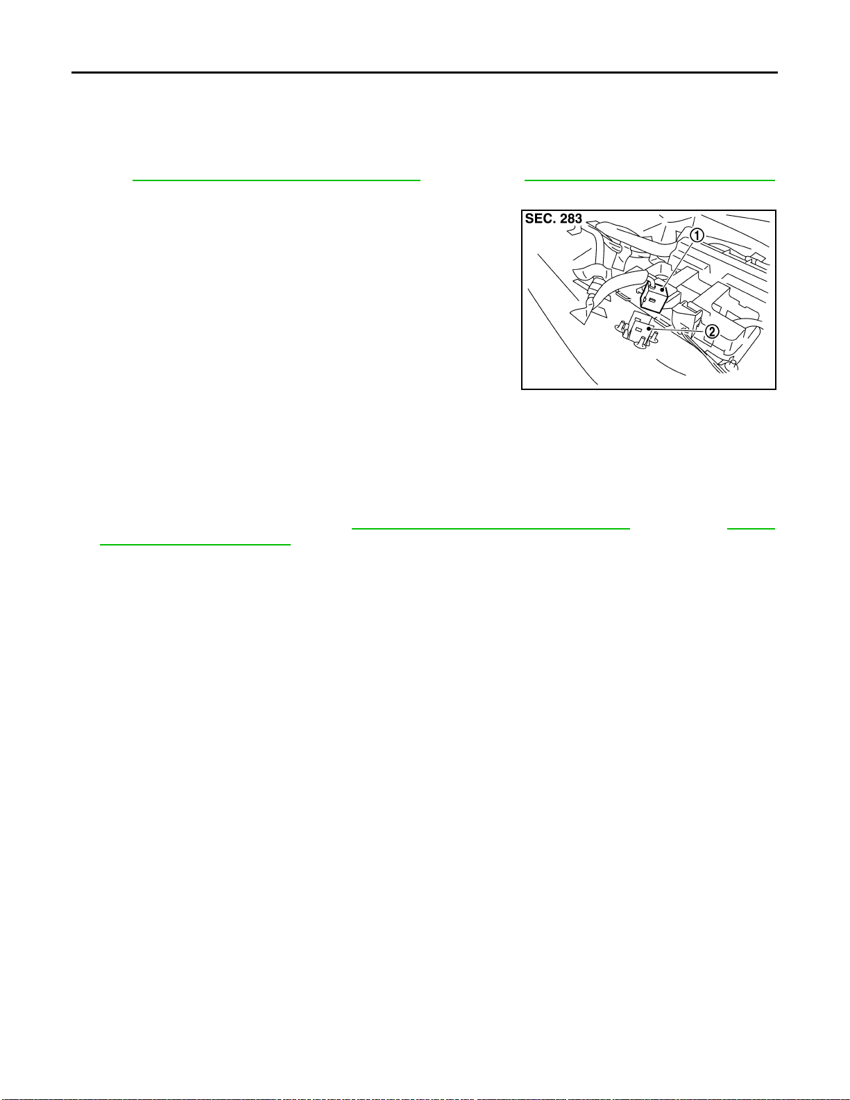
1. Microphone
2. Microphone cover
Removal and Installation INFOID:0000000001092925
REMOVAL
1. Remove headlining assembly. Refer to INT-22, "NORMAL ROOF : Exploded View" (Normal roof), INT-25,
"SUNROOF : Exploded View" (Sunroof).
2. Remove microphone.
INSTALLATION
Install in the reverse order of removal.
AV-42
Page 49
< ON-VEHICLE REPAIR >
RADIO ANTENNA
[AUDIO WITHOUT NAVIGATION]
RADIO ANTENNA
Exploded View INFOID:0000000001092926
JPNIA0325ZZ
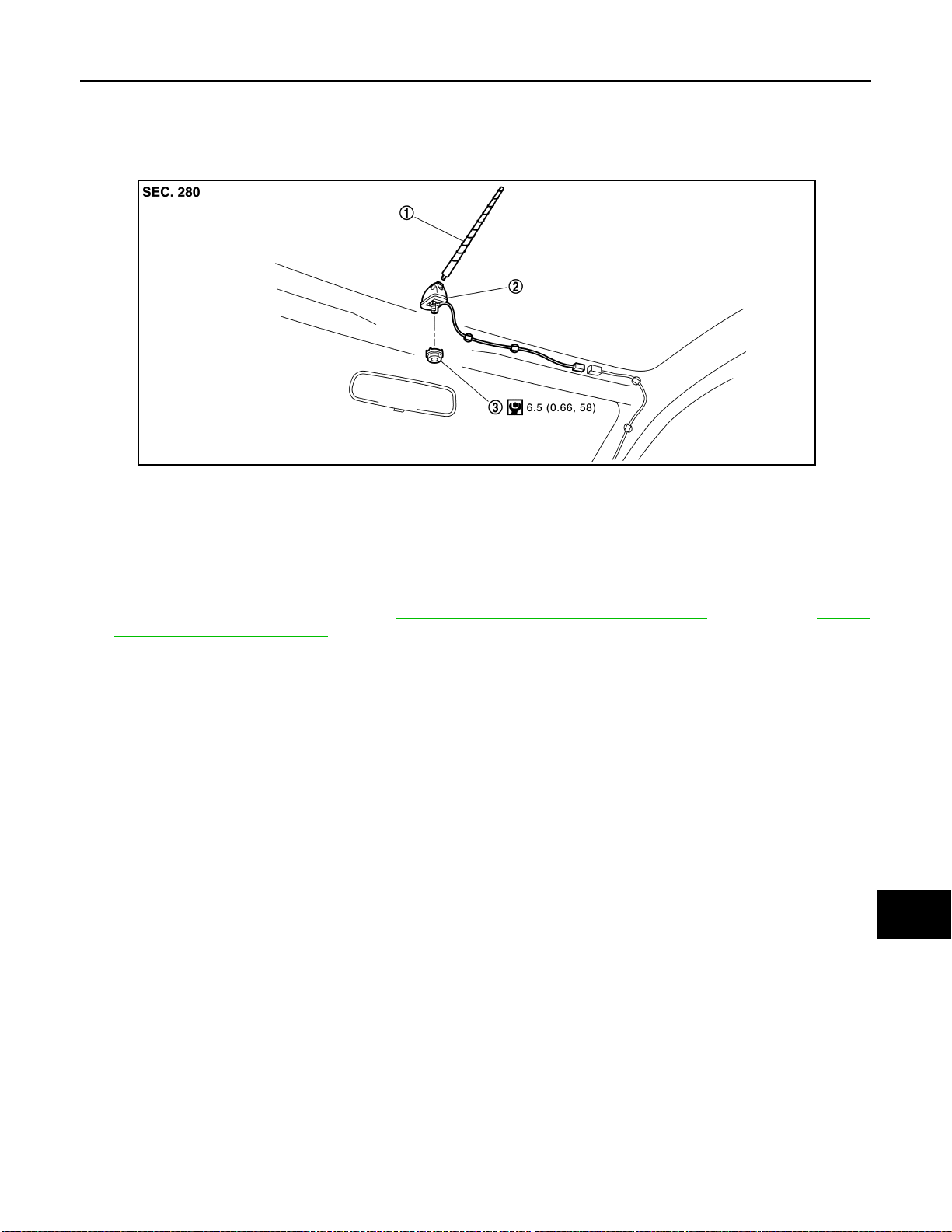
1. Antenna rod 2. Antenna base 3. Nut
Refer to GI-4, "
Removal and Installation INFOID:0000000001092927
Components" for symbols not described on the above.
A
B
C
D
E
F
G
H
REMOVAL
1. Remove headlining assembly. Refer to INT-22, "NORMAL ROOF : Exploded View" (Normal roof), INT-25,
"SUNROOF : Exploded View" (Sunroof).
2. Remove antenna base and antenna rod.
INSTALLATION
Install in the reverse order of removal.
I
J
K
L
M
AV
O
AV-43
P
Page 50
ANTENNA FEEDER (RADIO)
< ON-VEHICLE REPAIR >
[AUDIO WITHOUT NAVIGATION]
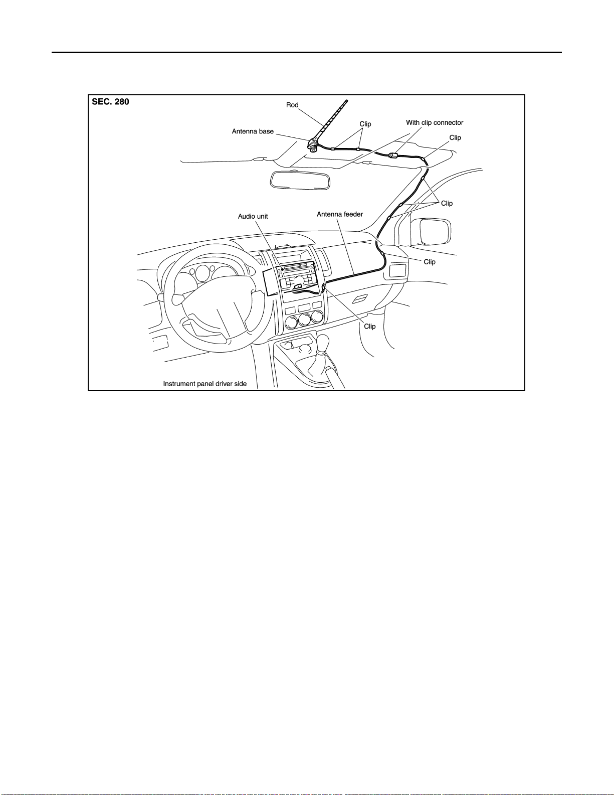
ANTENNA FEEDER (RADIO)
Harness Layout INFOID:0000000001092928
JPNIA0326GB
AV-44
Page 51
< BASIC INSPECTION >
DIAGNOSIS AND REPAIR WORKFLOW
[AUDIO WITH NAVIGATION]
BASIC INSPECTION
DIAGNOSIS AND REPAIR WORKFLOW
Work Flow INFOID:0000000001092929
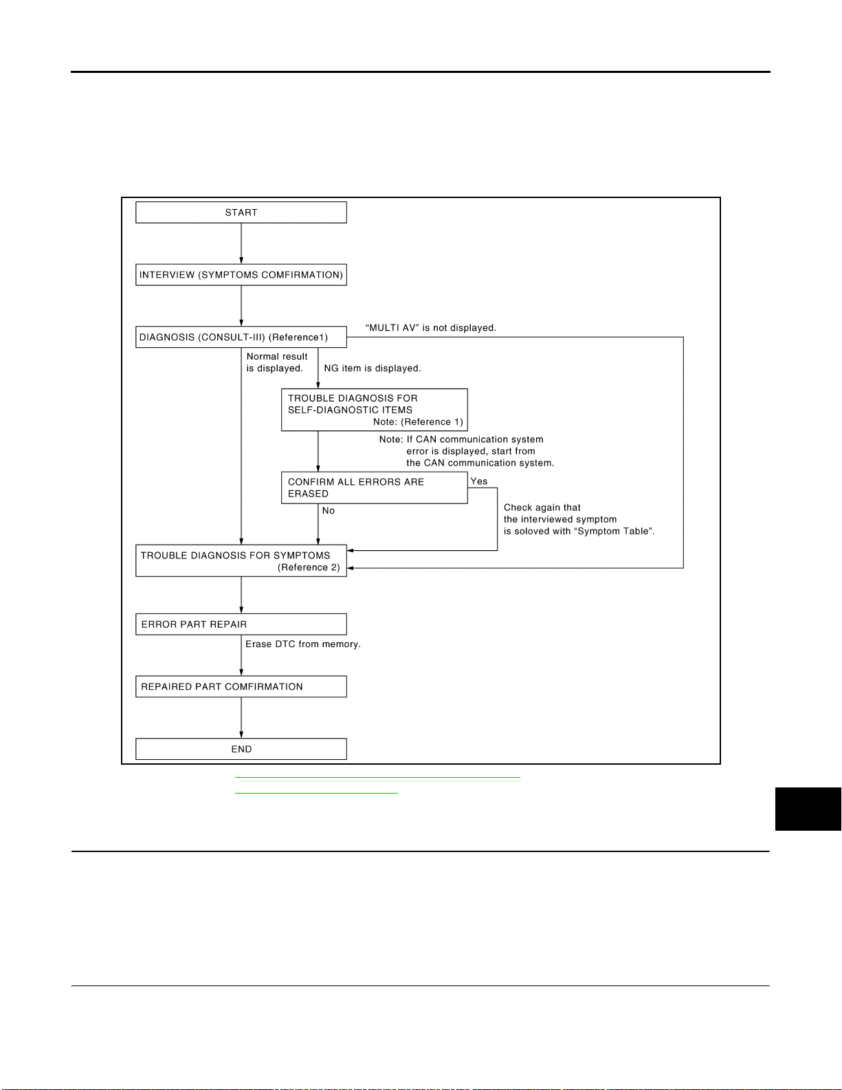
OVERALL SEQUENCE
A
B
C
D
E
F
G
H
JSNIA0039GB
• Reference 1··· Refer to AV-74, "CONSULT - III Function (MULTI AV)".
• Reference 2··· Refer to AV-248, "
Symptom Table".
DETAILED FLOW
1.CHECK SYMPTOM
Check the malfunction symptoms by performing the following items.
• Interview the customer to obtain the malfunction information (conditions and environment when the malfunc-
tion occurred).
• Check the symptom.
I
J
K
L
M
AV
O
P
>> GO TO 2.
2.SELF-DIAGNOSIS (CONSULT-III)
1. Connect CONSULT-III and perform a self-diagnosis for “MULTI AV”.
NOTE:
Skip to step 4 of the diagnosis procedure if “MULTI AV” is not displayed.
2. Check that any DTC No. is displayed in the self-diagnosis results.
AV-45
Page 52

DIAGNOSIS AND REPAIR WORKFLOW
< BASIC INSPECTION >
Is any DTC No. displayed?
YES >> GO TO 3.
NO >> GO TO 4.
[AUDIO WITH NAVIGATION]
3.CHECK SELF-DIAGNOSIS RESULTS (CONSULT-III)
1. Check the DTC No. indicated in the self-diagnosis results.
2. Perform the relevant diagnosis referring to the DTC Index. Refer to AV-159, "
NOTE:
Start with the diagnosis for the CAN communication system if “CAN COMM CIRCUIT [U1000] and CONTROL
UNIT CAN [U1010]” is displayed.
>> GO TO 5.
DTC Index".
4.PERFORM DIAGNOSIS BY SYMPTOM
Perform the relevant diagnosis referring to the diagnosis chart by symptom. Refer to AV-248, "
Table".
>> GO TO 5.
Symptom
5.REPAIR OR REPLACE MALFUNCTIONING PARTS
Repair or replace the identified malfunctioning parts.
NOTE:
Erase the stored self-diagnosis results after repairing or replaci ng the relevant components if any DTC No. has
been indicated in the self-diagnosis results.
>> GO TO 6.
6.CHECK AFTER REPAIR
1. Perform a self-diagnosis for “MULTI AV” with CONSULT-III after repairing or replacing the malfunctioning
parts.
2. Check that any DTC No. is displayed in the self-diagnosis results.
Is any DTC No. displayed?
YES >> GO TO 3.
NO >> GO TO 7.
7.FINAL CHECK
Perform the operation to check that the malfunction symptom is solved or any other symptoms are present.
Is there any symptom?
YES >> GO TO 4.
NO >> INSPECTION END
AV-46
Page 53

< BASIC INSPECTION >
INSPECTION AND ADJUSTMENT
[AUDIO WITH NAVIGATION]
INSPECTION AND ADJUSTMENT
ADDITIONAL SERVICE WHEN REMOVING BATTERY NEGATIVE TERMINAL
ADDITIONAL SERVICE WHEN REMOVING BATTERY NEGATIVE TERMINAL : Description INFOID:0000000001094790
Always correct the center position of the rear view monitor's possible route line after disconnecting the battery
negative terminal.
ADDITIONAL SERVICE WHEN REMOVING BATTERY NEGA TIVE TERMINAL : S pecial Repair Requirement INFOID:0000000001094791
1.CORRECTION OF CENTER POSITION OF REAR VIEW MONITOR'S POSSIBLE ROUTE LINE
Refer to the following for details.
>> Refer to AV-47, "
ADJUSTMENT : Special Repair Requirement".
ADDITIONAL SERVICE WHEN REPLACING CONTROL UNIT
ADDITIONAL SERVICE WHEN REPLACING CONTROL UNIT : Description
When camera control unit is replaced, the center position of rear view monitor possible route line shall be corrected.
REAR VIEW MONITOR POSSIBLE ROUTE LINE CENTER POSITION
INFOID:0000000001094792
A
B
C
D
E
F
G
H
ADDITIONAL SERVICE WHEN REPLACING CONTROL UNIT : Special Repair Requirement
INFOID:0000000001115045
1.CORRECTION OF CENTER POSITION OF REAR VIEW MONITOR'S POSSIBLE ROUTE LINE
Refer to the following for details.
>> Refer to AV-47, "
ADJUSTMENT : Special Repair Requirement".
REAR VIEW MONITOR POSSIBLE ROUTE LINE CENTER POSITION
REAR VIEW MONITOR POSSIBLE ROUTE LINE CENTER POSITION ADJUSTMENT
REAR VIEW MONITOR POSSIBLE ROUTE LINE CENTER POSITION ADJUSTMENT : Description
Adjust the center position of the possible route line of the rear view monitor if it is shifted.
INFOID:0000000001094794
REAR VIEW MONITOR POSSIBLE ROUTE LINE CENTER POSITION ADJUSTMENT : Special Repair Requirement
INFOID:0000000001094795
1.STEERING OPERATION
Steer the steering wheel to the leftmost and rightmost ends.
I
J
K
L
M
AV
O
>> GO TO 2
2.DRIVING
Drive the vehicle straight ahead 100 m (328.1 ft) or more at a speed of 30 km/h (18.6 MPH) or more.
>> END
AV-47
P
Page 54
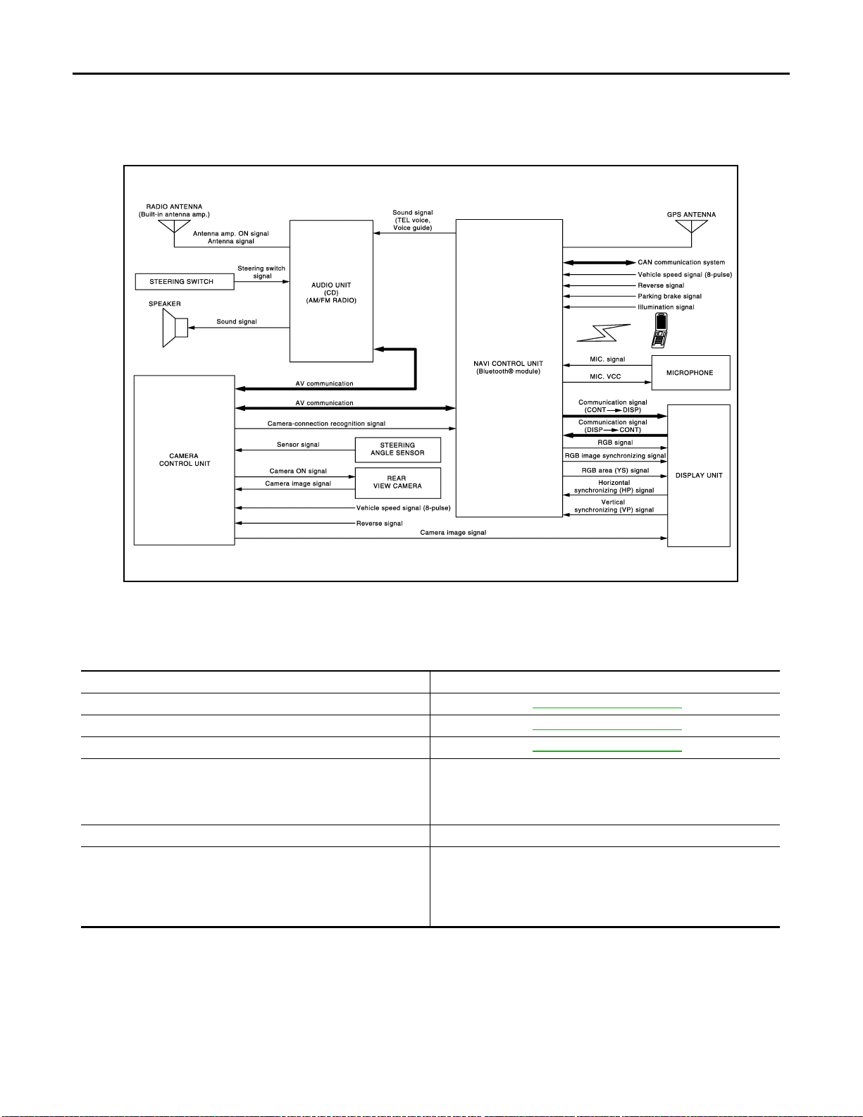
MULTI AV SYSTEM
< FUNCTION DIAGNOSIS >
[AUDIO WITH NAVIGATION]
FUNCTION DIAGNOSIS
MULTI AV SYSTEM
System Diagram INFOID:0000000001092930
JPNIA0241GB
System Description INFOID:0000000001092931
Multi AV system means that the following systems are integrated.
System name System explanation
NAVIGATION SYSTEM AV-52, "
AUDIO SYSTEM AV-60, "System Description"
REAR VIEW MONITOR SYSTEM AV-57, "System Description"
• Status of audio, maintenance and navigation is displayed.
VEHICLE INFORMATION SYSTEM
HANDS-FREE PHONE SYSTEM Refer to the following “HANDS-FREE PHONE SYSTEM”.
ANTI-THEFT SYSTEM
• NAVI control unit displays the maintenance information while
receiving data signal through CAN communication from combination meter.
This system verifies the immobilizer ID by CAN communication
between NAVI control unit and BCM every time the ignition
switch is turned to “ACC” position. Multi AV system can be permitted to operate only when the verification has successfully processed.
• Two AV communication lines (H, L) connect between units that configure MULTI AV system. NAVI control
unit controls by sending/receiving data one by one with each unit (slave unit) that configures them completely as a master unit.
• Two AV communication lines (H, L) adopt a twisted pair line that is resistant to noise.
• NAVI control unit is connected by CAN communication, and it receives data signal from ECM, combination
meter It computes and displays fuel economy information value with the obtained information. Sending/
receiving of data signal is performed by BCM. Also, it sends the required signal of vehicle setting and
receives the response signal.
System Description"
AV-48
Page 55
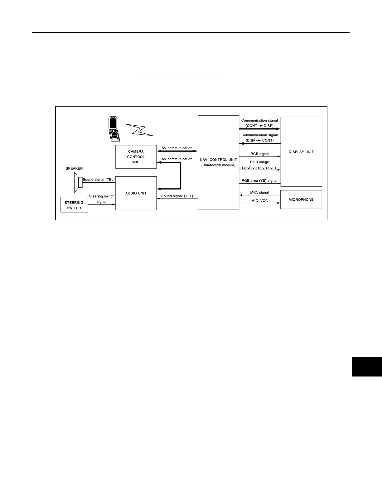
MULTI AV SYSTEM
< FUNCTION DIAGNOSIS >
• NAVI control unit i s connected with display and seri al communication, and it sends the required signal of display and display control and receives the response signal from front display.
NOTE:
NAVI control unit can perform CONSULT-III self-operating function and on board self-diagnosis.
• CONSULT-III self diagnosis: Refer to AV-74, "
• On board self diagnosis: Refer to AV-63, "
CONSULT - III Function (MULTI AV)".
Diagnosis Description".
HANDS-FREE PHONE SYSTEM
• Hands-free communication can be operated by connecting using Bluetooth® with cellular phone.
• Operation is performed by steering switch or audio switch, and operating condition is indicated on display.
[AUDIO WITH NAVIGATION]
A
B
C
D
E
F
G
JPNIA0243GB
When a call is originated
Spoken voice sound output from the microphone (mic. signal) is input to NAVI control unit. NAVI control unit
®
outputs to cellular phone with Bluetooth
communication as a TEL voice signal. Voice sound is then heard at
the other party.
When receiving a call
Voice sound is input to own cell ular phone from the other party. TEL voice signal is output to front speaker, and
the signal is input to audio unit via NAVI control unit by establishing Bluetooth
®
communication from cellular
phone.
H
I
J
K
L
M
AV
O
AV-49
P
Page 56
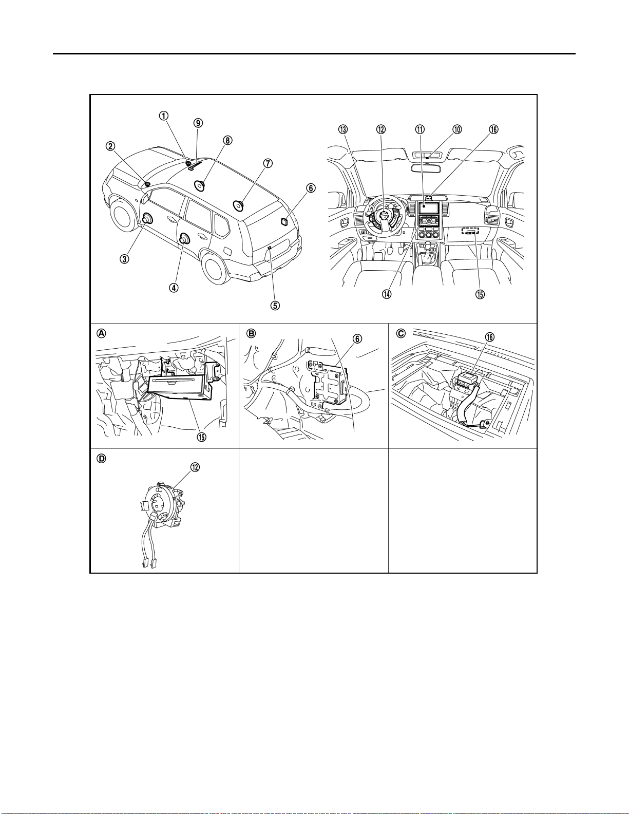
< FUNCTION DIAGNOSIS >
MULTI AV SYSTEM
[AUDIO WITH NAVIGATION]
Component Parts Location
INFOID:0000000001092932
1. Tweeter RH 2. Tweeter LH 3. Front door speaker LH
4. Rear door speaker LH 5. Rear view camera 6. Camera control unit
7. Rear door speaker RH 8. Front door speaker RH 9. Radio antenna
10. Microphone 11. Display unit 12. Steering angle sensor
13. Steering switch 14. Audio unit 15. NAVI control unit
16. GPS antenna
A. Inside glove box B. Trunk room RH C. Back of a display unit
D. Spiral cable part
AV-50
JPNIA0315ZZ
Page 57
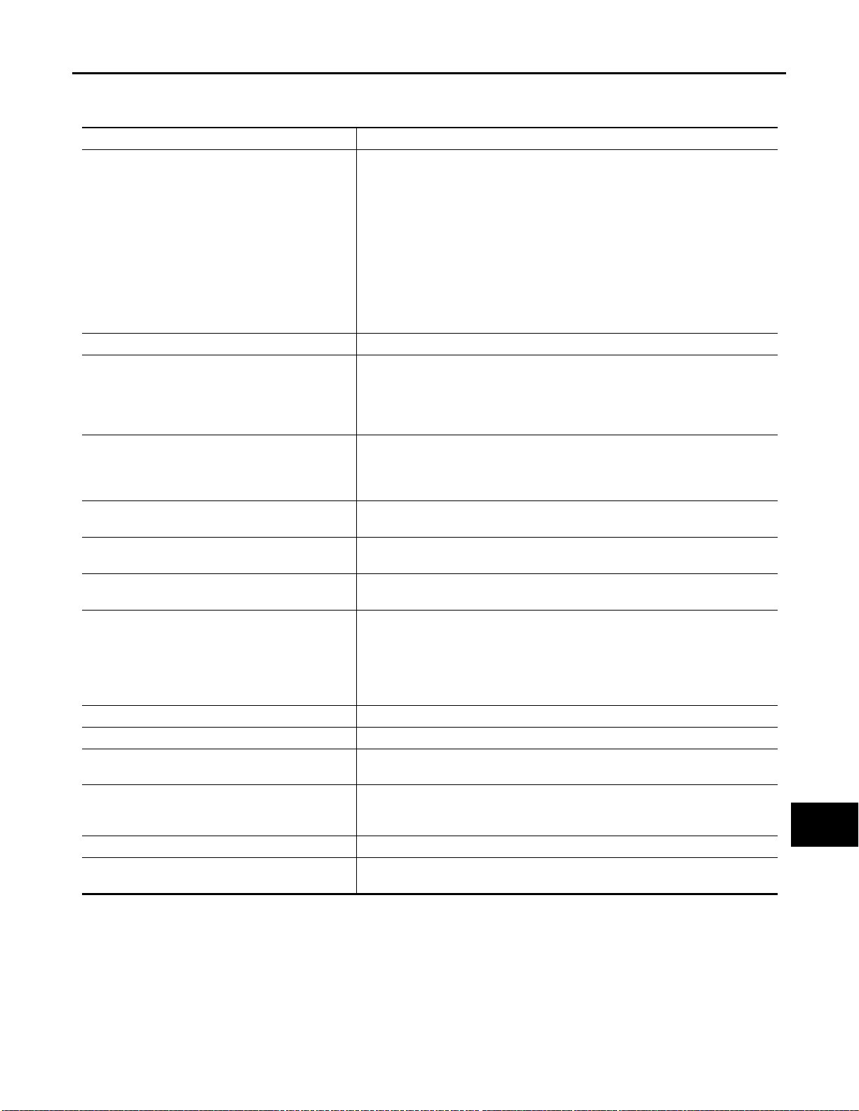
MULTI AV SYSTEM
< FUNCTION DIAGNOSIS >
[AUDIO WITH NAVIGATION]
Component Description INFOID:0000000001092933
Part name Description
• Map data can be read from the Map DVD-ROM by installing Map DVD-ROM.
• It is th e master uni t of the MULTI AV system, an d it is con nected to eac h control unit by means of communication. It operates each system according to
communication signals from the NAVI control unit.
• The NAVI control unit includes the audio, hands-free phone, navig ation, and
NAVI CONTORL UNIT
MAP DVD-ROM A collection of Map data.
DISPLAY UNIT
AUDIO UNIT
FRONT DOOR SPEAKER
REAR DOOR SPEAKER
TWEETER
CAMERA CONTROL UNIT
REAR VIEW CAMERA The image of vehicle rear view is sent to camera control unit.
STEERING ANGLE SENSOR Sensor signal (steering angle) is sent to camera control unit.
STEERING SWITCH
MICROPHONE
GPS ANTENNA GPS signal is received and sent to NAVI control unit.
RADIO ANTENNA (Built-in antenna amp.)
vehicle information functions.
• The NAVI control unit displays the maintenance information while receiving
data signal through CAN communication from combination meter.
• It inputs the illumination signals that are required for the display dimming control.
• It input s the signals for drivin g status recogniti on (vehicle speed, reverse an d
parking brake).
• Display image is controlled by the serial communication from NAVI control
unit.
• RGB image signal is input from NAVI control unit (RGB, RGB area and RGB
synchronizing). Camera image signal is input from camera contro l unit.
• Synchronize signal (HP, VP) is output to NAVI control unit.
• Operational switch of MULTI AV system is integrated.
• Audio unit are connected to NAVI control unit with AV communication via
camera control unit. Operating signa ls of the switch are sent to the NA VI control unit.
• Outputs sound signal from audio unit.
• Outputs high, mid and low range sounds.
• Outputs sound signal from audio unit.
• Outputs high, mid and low range sounds.
• Outputs sound signal from audio unit.
• Outputs high range sound.
• Camera ima ge signal is input from rear view camera, and camera image is
indicated on the display.
• Power (camera ON signal) is sent to rear view camera.
• Controlled by AV communication sent from NAVI control unit.
• NAVI control unit recognizes the presence of camera system with camera
connection recognition signal.
• Operations for audio, hands-free phone and navigation, etc. are possible.
• Steering switch signa l (operation signal) is output to audio unit.
• Used for hands-free phone operation.
• Mic. signal is sent to NAVI control unit.
• Power (Mic. VCC) is supplied from NAVI control unit.
• Radio signal received by radio antenna is amplified and sent to audio unit.
• Power (antenna amp. ON signal) is supplied from audio unit.
A
B
C
D
E
F
G
H
I
J
K
L
M
AV
O
AV-51
P
Page 58
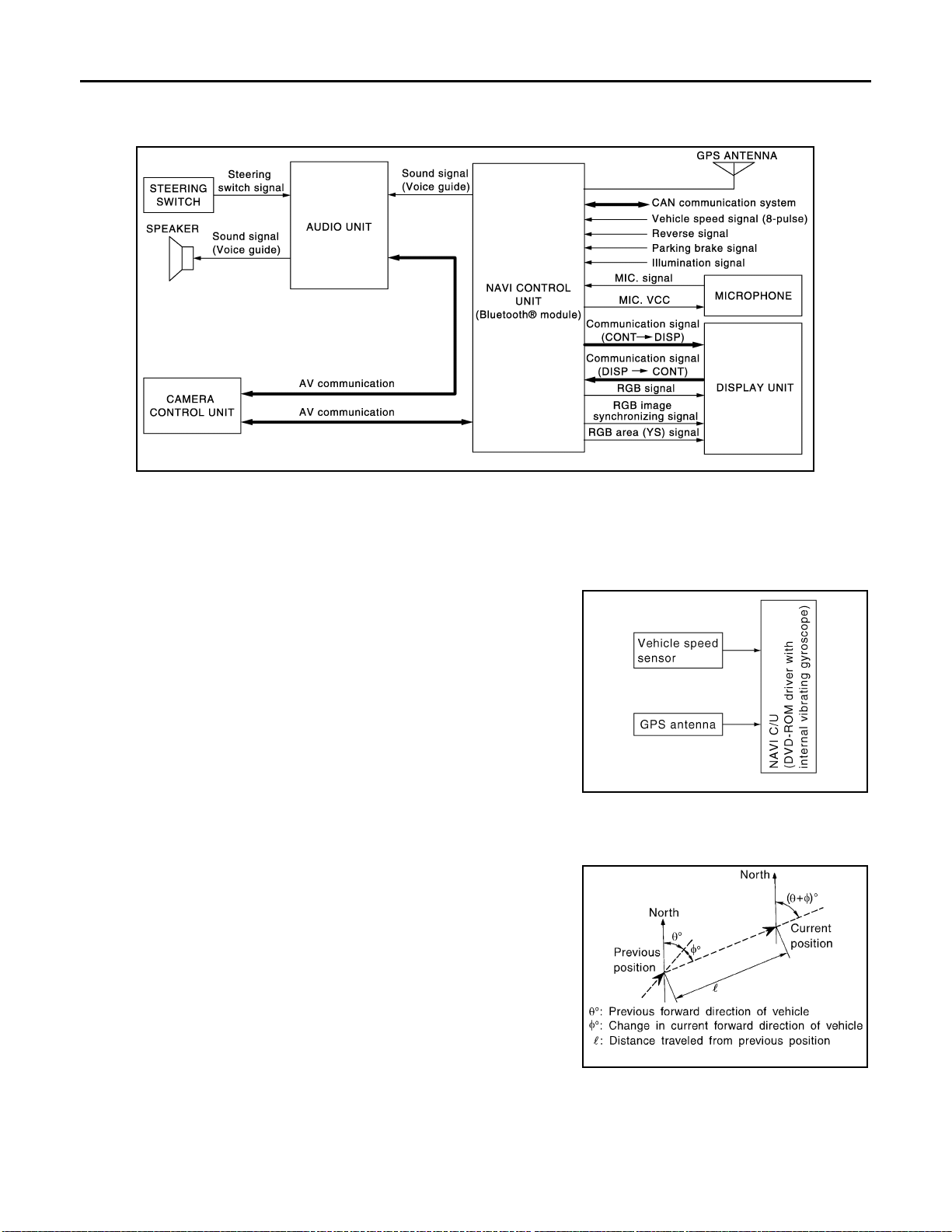
NAVIGATION SYSTEM
< FUNCTION DIAGNOSIS >
[AUDIO WITH NAVIGATION]
NAVIGATION SYSTEM
System Diagram INFOID:0000000001092934
JPNIA0245GB
System Description INFOID:0000000001092935
NAVIGATION SYSTEM
Location Detection Principle
The navigation system periodically calculates the vehicle's current
position according to the following three signals:
• Travel distance of the vehicle as determined by the vehicle speed
sensor
• Turning angle of the vehicle as determined by the gyroscope
(angular velocity sensor)
• Direction of vehicle travel as determined by the GPS antenna
(GPS information)
The current position of the vehicle is then identified by comparing the
calculated vehicle position with map data read from the map DVDROM, which is stored in the DVD-ROM drive (map-matching), and
indicated on the screen as a vehicle mark. More accurate data is
judged and used by comparing vehicle position detection results found by the GPS with the result by mapmatching.
The current vehicle position will be calculated by detecting the distance the vehicle moved from the previous calculation point and its
direction.
• Travel distance
Travel distance calculations are based on the vehicle speed sensor input signal. Therefore, the calculation may become incorrect
as the tires wear down. To prevent this, an automatic distance correction function has been adopted.
• Travel direction
Change in the travel direction of the vehicle is calculated by a gyroscope (angular velocity sensor) and a GPS antenna (GPS information). They have both advantages and disadvantages.
SKIB1058E
SEL684V
AV-52
Page 59
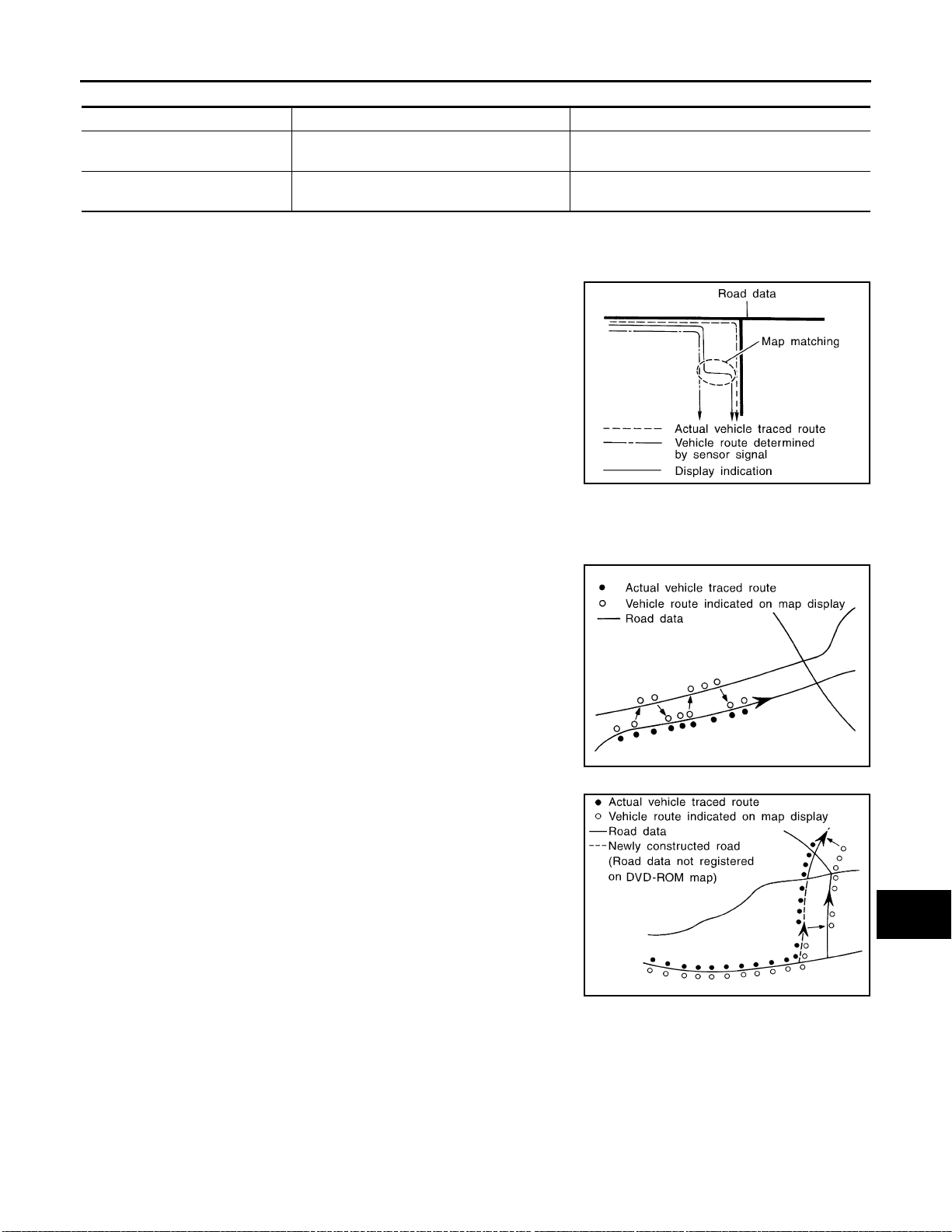
< FUNCTION DIAGNOSIS >
NAVIGATION SYSTEM
[AUDIO WITH NAVIGATION]
Type Advantage Disadvantage
Gyroscope
(angular velocity sensor)
GPS antenna
(GPS information)
Can detect the vehicle's turning angle quite
accurately.
Can detect the vehicle's travel direction
(North/South/East/West).
Direction errors may accumulate when vehicle is
driven for long distances without stopping.
Correct direction cannot be de tected when vehicle
speed is low.
More accurate traveling direction is detected because priorities are set for the signals from these two
devices according to the situation.
Map-Matching
Map-matching compares a current location detected by the method
in the “Location Detection Principle” with a road map data from Map
DVD-ROM stored in DVD-ROM drive.
NOTE:
The road map data is based on data stored in the map DVD-ROM.
SEL685V
The vehicle position may not be corrected under the following circumstances and after driving for a certain
time when GPS information is difficult to receive. In this case, the vehicle mark on the display must be corrected manually.
• In map-matching, alternative routes to reach the destination will be
shown and prioritized, after the road on which the vehicle is currently driven has been judged and the vehicle mark has been repositioned.
Alternative routes will be shown in different order of priority, and
the incorrect road can be avoided if there is an error in distance
and/or direction.
They are of the same priority if two roads are running in parallel.
Therefore, the vehicle mark may appear on either of them alternately, depending on maneuvering of the steering wheel and configuration of the road.
SEL686V
A
B
C
D
E
F
G
H
I
J
K
• Map-matching does not function correctly when a road on which
the vehicle is driving is new and not recorded in the map DVDROM, or when road pattern stored in the map data and the actual
road pattern are different due to repair.
The map-matching function may find another road and position the
vehicle mark on it when driving on a road not present in the map.
Then, the vehicle mark may change to it when the correct road is
detected.
• Effective range for comparing the vehicle position and travel direction calculated by the distance and direction with the road data
read from the map DVD-ROM is limited. Therefore, correction by
map-matching is not possible when there is an excessive gap
between current vehicle position and the position on the map.
GPS (Global Positioning System)
AV-53
SKIA0613E
L
M
AV
O
P
Page 60
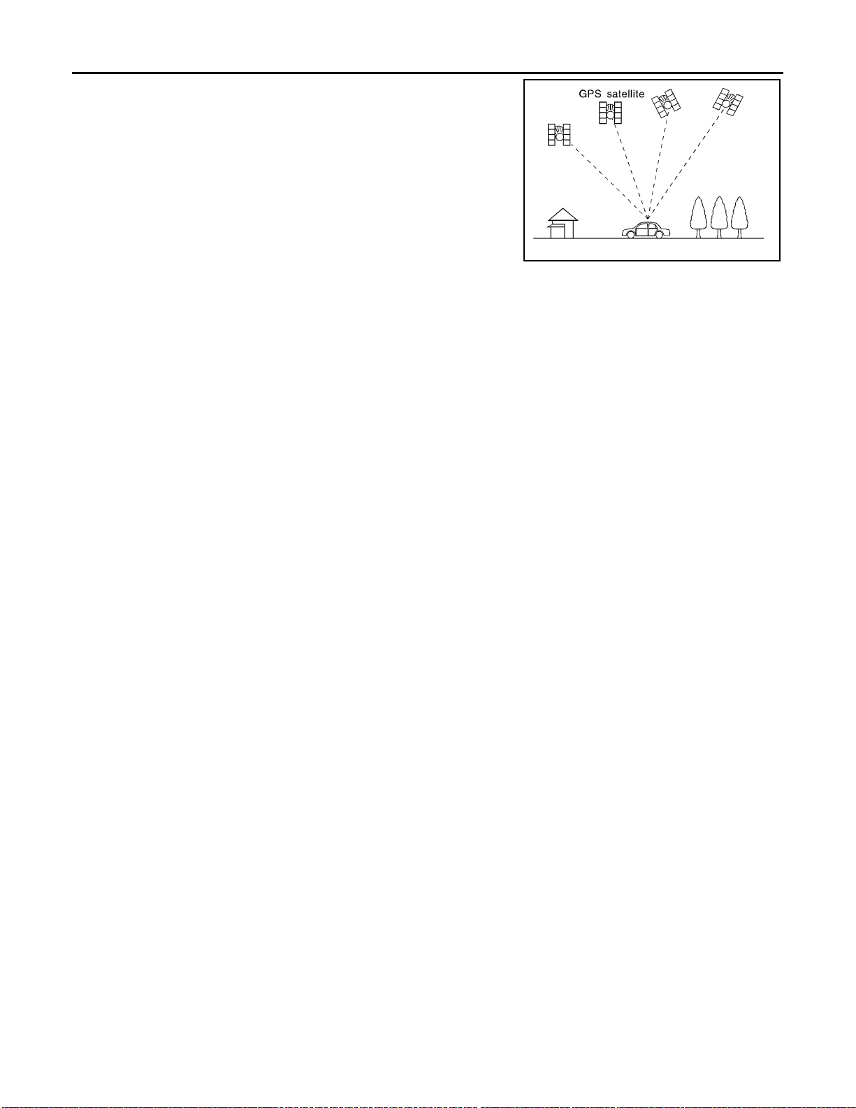
NAVIGATION SYSTEM
< FUNCTION DIAGNOSIS >
GPS (Global Positioning System) was developed for and is controlled by the US Department of Defense. The system utilizes GPS
satellites (NAVSTAR), sending out radio waves while flying on an
orbit around the earth at an altitude of approximately 21,000 km
(13,100miles).
The GPS receiver calculates the vehicle's position in three dimensions (latitude/longitude/altitude) according to the time lag of the
radio waves received from four or more GPS satellites (three-dimensional positioning). The GPS receiver calculates the vehicle's position in two dimensions (latitude/longitude), utilizing the altitude data
calculated previously with radio waves from four or more GPS satellites (two-dimensional positioning) if radio waves were received only
from three GPS satellites.
Position correction by GPS is not available while the vehicle is stopped.
Accuracy of GPS will deteriorate under the following conditions:
• In two-dimensional positioning, GPS accuracy will deteriorate when altitude of the vehicle position changes.
• The accuracy can be even lower depending on the arrangement of the GPS satellites utilized for the positioning.
• Position detection is not possible when vehicle is in an area where radio waves from the GPS satellite do not
reach, such as in a tunnel, parking lot in a building, and under an elevated highway. Radio waves from the
GPS satellites may not be received when some object is located over the GPS antenna.
NOTE:
• Even a high-precision three dimensional positioning, the detection result has an error about 10 m (30ft).
• Because the signals of GPS satellite is controlled by the Tracking and Control Center in the United States,
the accuracy may be degraded lower intentionally or the radio waves may stop.
[AUDIO WITH NAVIGATION]
SEL526V
Traffic Information (RDS-TMC)
NOTE: RDS-TMC tuner is built-in audio unit.
The traffic information broadcast allows to you to avoid delays due to traffic incidents.
Traffic jams, roadwork, closed roads around your current location, etc. are represented graphically on the map
by icons depicting the nature of the event.
Incidents on the route are automatically brought to your attention when they are approached.
The Traffic Information feature gives you the opportunity to forecast traffic incidents, determine how serious
they are, via the guidance mode, and allows you to detour around traffic incidents.
The navigation system receives traffic information from best available sources and enables the RDS-TMC
(Radio Data System-Traffic Information Channel) to inform and guide you.
The RDS-TMC broadcast is fed by an audio unit so that you can still tune your radio station while Traf fic Information is being broadcasted.
AV-54
Page 61
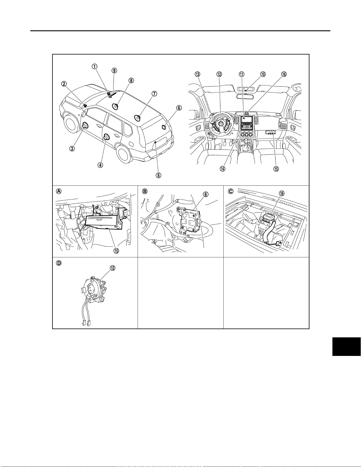
NAVIGATION SYSTEM
< FUNCTION DIAGNOSIS >
[AUDIO WITH NAVIGATION]
Component Parts Location INFOID:0000000001093556
A
B
C
D
E
F
G
1. Tweeter RH 2. Tweeter LH 3. Front do or speaker LH
4. Rear door speaker LH 5. Rear view camera 6. Camera control unit
7. Rear door speaker RH 8. Front door speaker RH 9. Radio antenna
10. Microphone 11. Display unit 12. Steering angle sensor
13. Steering switch 14. Audio unit 15. NAVI control unit
16. GPS antenna
A. In sid e glo v e box B. Trunk room RH C. Bac k of a displ ay unit
D. Spiral cable part
JPNIA0315ZZ
H
I
J
K
L
M
AV
O
P
AV-55
Page 62

< FUNCTION DIAGNOSIS >
NAVIGATION SYSTEM
[AUDIO WITH NAVIGATION]
Component Description
Part name Description
• The master unit controls each operation of the Navigation system.
NAVI CONTORL UNIT
MAP DVD-ROM A collection of Map data
DISPLAY UNIT
AUDIO UNIT
FRONT DOOR SPEAKER
TWEETER
STEERING SWITCH
GPS ANTENNA GPS signal is received and is output to NAVI control unit.
• Map data can be read from the Map DVD-ROM by installing Map DVD-ROM.
• The RGB signal (map information) is output to the dis play.
• The voice guidance signal is output to the audio unit.
Map image signal is input from NAVI control unit, and it is indicated on the display.
• Voice guidance signa l is in pu t from NAVI control unit, and voice guidance is
output to front LH/RH speakers.
• Each operation of navigation can be performed.
Voice guidance signal from audio unit is output.
• Each operation of navigation, etc. can be performed.
• Switch operating signal is output to NAVI control unit via audio unit and camera control unit with AV communication.
INFOID:0000000001092937
AV-56
Page 63
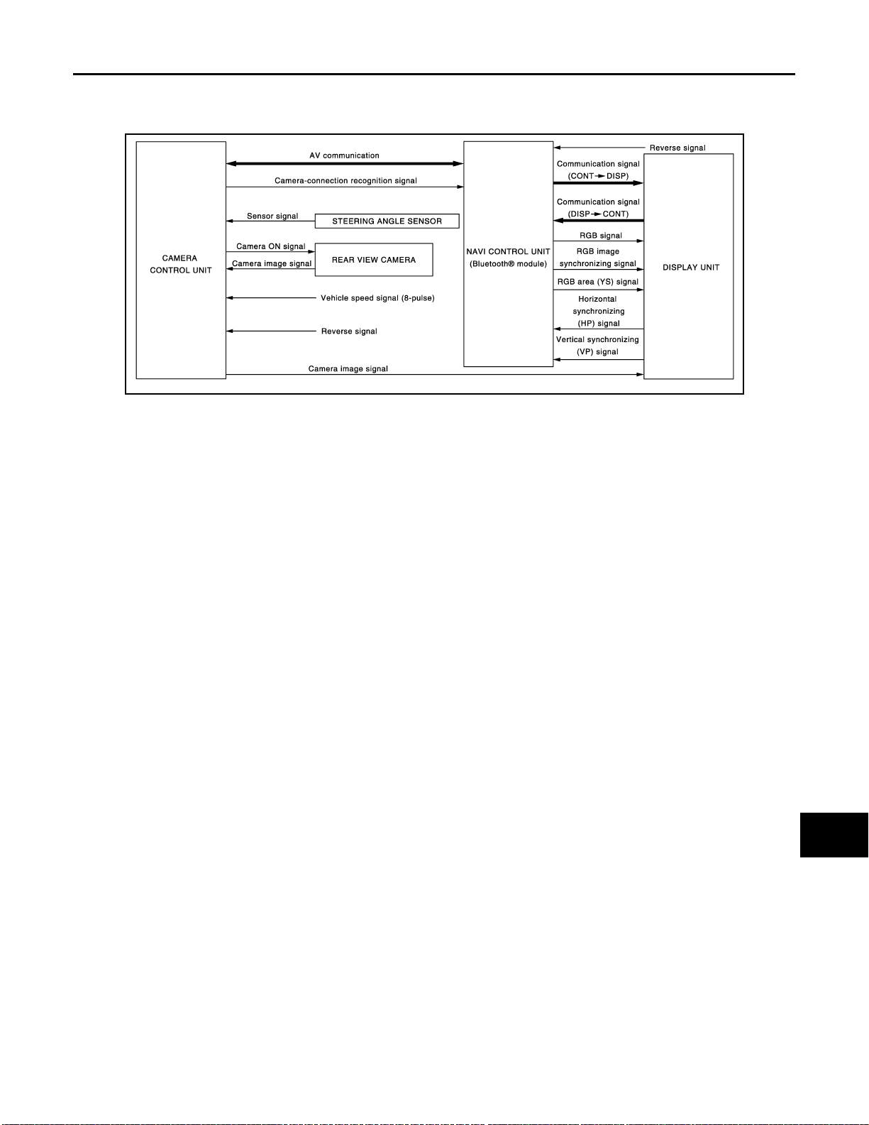
< FUNCTION DIAGNOSIS >
REAR VIEW MONITOR SYSTEM
[AUDIO WITH NAVIGATION]
REAR VIEW MONITOR SYSTEM
System Diagram INFOID:0000000001092938
JPNIA0244GB
System Description INFOID:0000000001094472
Camera image operation principle
• Power is supplied to rear view camera from camera control unit and outputs camera image signal to camera
control unit when shift position is set to R position and the reverse signal on camera control unit is input.
• Camera control unit synthesizes guide lines and possible route lines with camera image signal from rear
view camera, and transmits camera image signal to the display. In this case, since the reverse signal is also
input to NAVI control unit, the NAVI control unit recognizes the shift position as in R position, and it switches
communication signal between NAVI control unit and display unit, and image that is displayed on the display
unit by RGB signal with rear view monitor image. In addition, possible route lines are controlled by original
sensor signal from steering angle sensor.
• The NAVI control unit determines whether rear view camera is equipped or not, based on the presence of
camera connection recognition signal. It switches to rear view monitor image at the time of reverse signal
input when it is not equipped.
• Warning message under the rear view monitor display is described by NAVI control unit.
• NAVI control unit is connected in communication with camera control unit and display unit, and it controls
operation of rear view monitor system.
A
B
C
D
E
F
G
H
I
J
K
AV-57
L
M
AV
O
P
Page 64
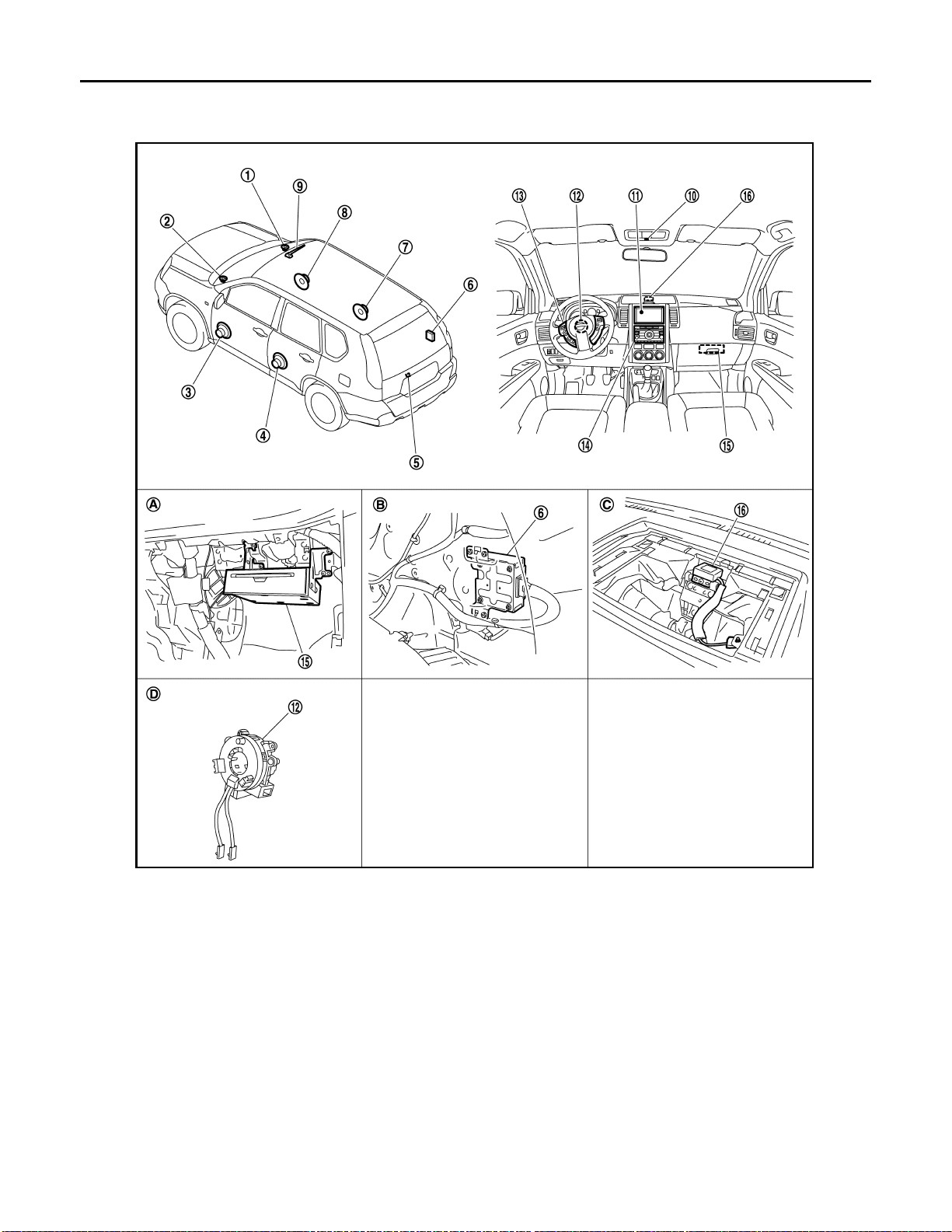
< FUNCTION DIAGNOSIS >
REAR VIEW MONITOR SYSTEM
[AUDIO WITH NAVIGATION]
Component Parts Location
INFOID:0000000001093555
1. Tweeter RH 2. Tweeter LH 3. Front door speaker LH
4. Rear door speaker LH 5. Rear view camera 6. Camera control unit
7. Rear door speaker RH 8. Front door speaker RH 9. Radio antenna
10. Microphone 11. Display unit 12. Steering angle sensor
13. Steering switch 14. Audio unit 15. NAVI control unit
16. GPS antenna
A. Inside glove box B. Trunk room RH C. Back of a display unit
D. Spiral cable part
AV-58
JPNIA0315ZZ
Page 65

REAR VIEW MONITOR SYSTEM
< FUNCTION DIAGNOSIS >
[AUDIO WITH NAVIGATION]
Component Description INFOID:0000000001094699
Part name Description
• Image on displ ay is changed to rear view monitor with the communication for
NAVI CONTORL UNIT
DISPLAY UNIT
CAMERA CONTROL UNIT
REAR VIEW CAMERA The image of vehicle rear view is sent to camera control unit.
STEERING ANGLE SENSOR
camera control unit and display unit.
• Warning displayed in rear view monitor image is illustrated.
• Camera image signal is sent from camera control unit , and RGB signal for
warning display is sent from NAVI control unit.
• Rear view mon itor image is changed with the com munication for NA VI control
unit.
• Camera ima ge signal is input from rear view camera, and camera image is
indicated on the display.
• Power (camera ON signal) is sent to rear view camera.
• Controlled by AV communication sent from NAVI control unit.
• NAVI control unit recognizes the presence of camera system with camera
connection recognition signal.
Steering signal necessary for possible route line control is sent to camera control unit.
A
B
C
D
E
F
G
AV
H
I
J
K
L
M
O
AV-59
P
Page 66
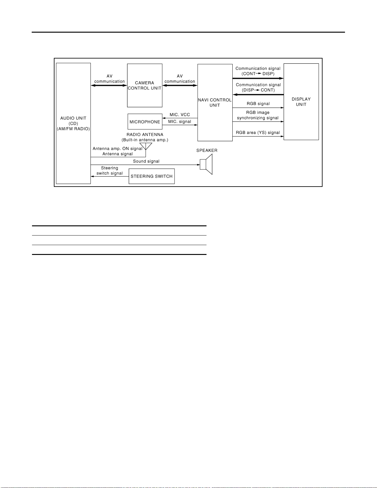
AUDIO SYSTEM
< FUNCTION DIAGNOSIS >
[AUDIO WITH NAVIGATION]
AUDIO SYSTEM
System Diagram INFOID:0000000001092942
JPNIA0242GB
System Description INFOID:0000000001092943
The audio system is equipped with following function. Each function is operated with audio switch or steering switch. Operation status of AUDIO
is indicated at display.
Function
AM/FM radio
CD
FUNCTION DESCRIPTION
Operating signal
Audio system operation can be performed with audio switch or steering switch.
Screen display
• Switching of display is performed with serial communication between display and NAVI control unit.
• The image signal to display operating condition is performed with RGB signal, RGB area signal and RGB
image synchronizing signal.
AM/FM Radio Mode
• AM/FM radio tuner is built into audio unit.
• Audio signal is received by antenna, next it is amplified by antenna amp., and finally it is input to audio unit.
Audio unit outputs the audio signal to each speaker.
CD Mode
• CD function is built into audio unit.
• Audio unit outputs audio signal to each speaker when CD is inserted to audio unit.
SPEED SENSITIVE VOLUME
• Volume level of this system gone up and down automatically in proportion to the vehicle speed. And the control level can be selected by the customer.
• The audio unit inputs the vehicle signal that is sent from combination meter via CAN communication through
NAVI control unit.
AV-60
Page 67
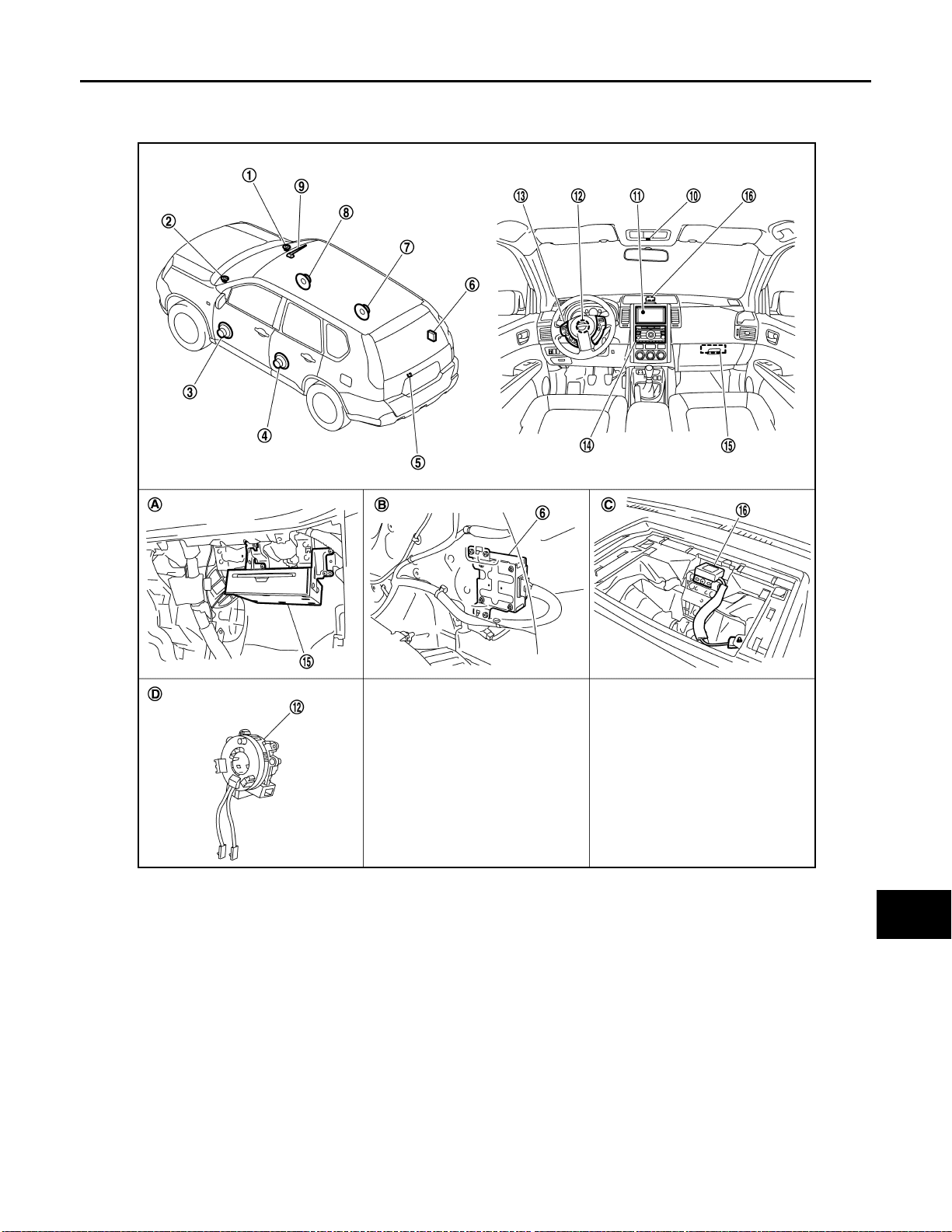
AUDIO SYSTEM
< FUNCTION DIAGNOSIS >
[AUDIO WITH NAVIGATION]
Component Parts Location INFOID:0000000001093557
A
B
C
D
E
F
G
1. Tweeter RH 2. Tweeter LH 3. Front do or speaker LH
4. Rear door speaker LH 5. Rear view camera 6. Camera control unit
7. Rear door speaker RH 8. Front door speaker RH 9. Radio antenna
10. Microphone 11. Display unit 12. Steering angle sensor
13. Steering switch 14. Audio unit 15. NAVI control unit
16. GPS antenna
A. In sid e glo v e box B. Trunk room RH C. Bac k of a displ ay unit
D. Spiral cable part
JPNIA0315ZZ
H
I
J
K
L
M
AV
O
P
AV-61
Page 68

< FUNCTION DIAGNOSIS >
AUDIO SYSTEM
[AUDIO WITH NAVIGATION]
Component Description
Part name Description
AUDIO UNIT
DISPLAY UNIT
FRONT DOOR SPEAKER
REAR DOOR SPEAKER
TWEETER
STEERING SWITCH
RADIO ANTENNA (Built-in antenna amp.)
INFOID:0000000001092945
• Operational switch of audio system is integrated.
• Receiving function of AM/FM radio, replaying function of CD are integrated.
• Audio signals are output to each speak er.
• Display image is controlled by the serial communication from NAVI control
unit.
• RGB image sign al (audio operati on condition) i s input from NAVI control unit.
• Outputs sound signal from audio unit.
• Outputs high, mid and low range sounds.
• Outputs sound signal from audio unit.
• Outputs high, mid and low range sounds.
• Outputs sound signal from audio unit.
• Outputs high range sound.
• Each audio operation can be operated.
• Steering switch signal (operation signal) is output to audio unit.
• Radio signal received by radio antenna is amplified and sent to audio unit.
• Power (antenna amp. ON signal) is supplied from audio unit.
AV-62
Page 69

DIAGNOSIS SYSTEM (NAVI CONTROL UNIT)
< FUNCTION DIAGNOSIS >
[AUDIO WITH NAVIGATION]
DIAGNOSIS SYSTEM (NAVI CONTROL UNIT)
Diagnosis Description INFOID:0000000001092946
MULTI AV SYSTEM on board diagnosis function
• The NAVI control unit diagnosis function starts up with audio switch operation and the NAVI control unit performs a diagnosis for each unit in the system during the on board diagnosis.
• Perform a CONSULT-III diagnosis if the on board diagnosis does not start, e.g., the screen does not display
anything, the multifunction switch does not function. etc.
On board diagnosis
Description
• The trouble diagnosis function has a self-diagnosis mode for conducting trouble diagnosis automatically and
a confirmation/adjustment mode for operating manually.
• The self-diagnosis mode performs diagnoses on the NAVI control unit, connections between system components as well as connections between NAVI control unit and GPS antenna. Then it displays the diagnosis
results on the display.
• The confirmation/adjustment mode allows the technician to check, modify or adjust the vehicle signals and
set values, as well as to monitor the system error records and system communication status. The check,
modify or adjust actions generally require human intervention and judgment (the system cannot make judgment automatically).
On board diagnosis item
Mode Description
• NAVI control unit diagnosis
Self Diagnosis
Confirmation/
Adjustment
Display Diagnosis
Vehicle Signals
Speaker Test The connection of a speaker can be confirmed by test tone.
Steering Angle Ad-
Navigation
Error History
Vehicle CAN Diagnosis The transmitting/receiving of CAN communication can be monitored.
AV COMM Diagnosis
Handsfree Phone
Camera Cont.
Bluetooth The passkey and the device name can be checked and changed.
Delete Unit Connection Log Erase the connection history of unit and error his tory.
Feature Restriction Setting
justment
Speed Calib ration
• Diagnoses the connections across system components, between
NAVI control unit and GPS antenna.
The following check functions are available: color tone check by color
bar display, light and shade check by gray scale display.
Diagnosis of signals can be performed for vehicle speed, parking
brake, lights, ignition, and reverse.
A difference can be adjusted between the actual turning angle and the
vehicle mark turning angle.
A difference can be adju sted between the current locati on mark and the
actual location.
The system malfunction and th e frequency when occurred in the past
are displayed. The time and place that the selected malfunction last occurred are displayed when the malfunctioning item is selected.
The communication condition of each unit of Multi AV system can be
monitored.
The received volume adjustme nt of hands-free phone, microphone
speaker check, and erase memory can be performed .
The signal connected to camera control unit can be checked and the
guiding line position that overlaps rear view camera image can be adjusted.
Operations of navigation system while driving can be restricted by using this function.
A
B
C
D
E
F
G
H
I
J
K
L
M
AV
O
P
STARTING PROCEDURE
1. Start the engine.
2. Turn the audio system OFF.
AV-63
Page 70
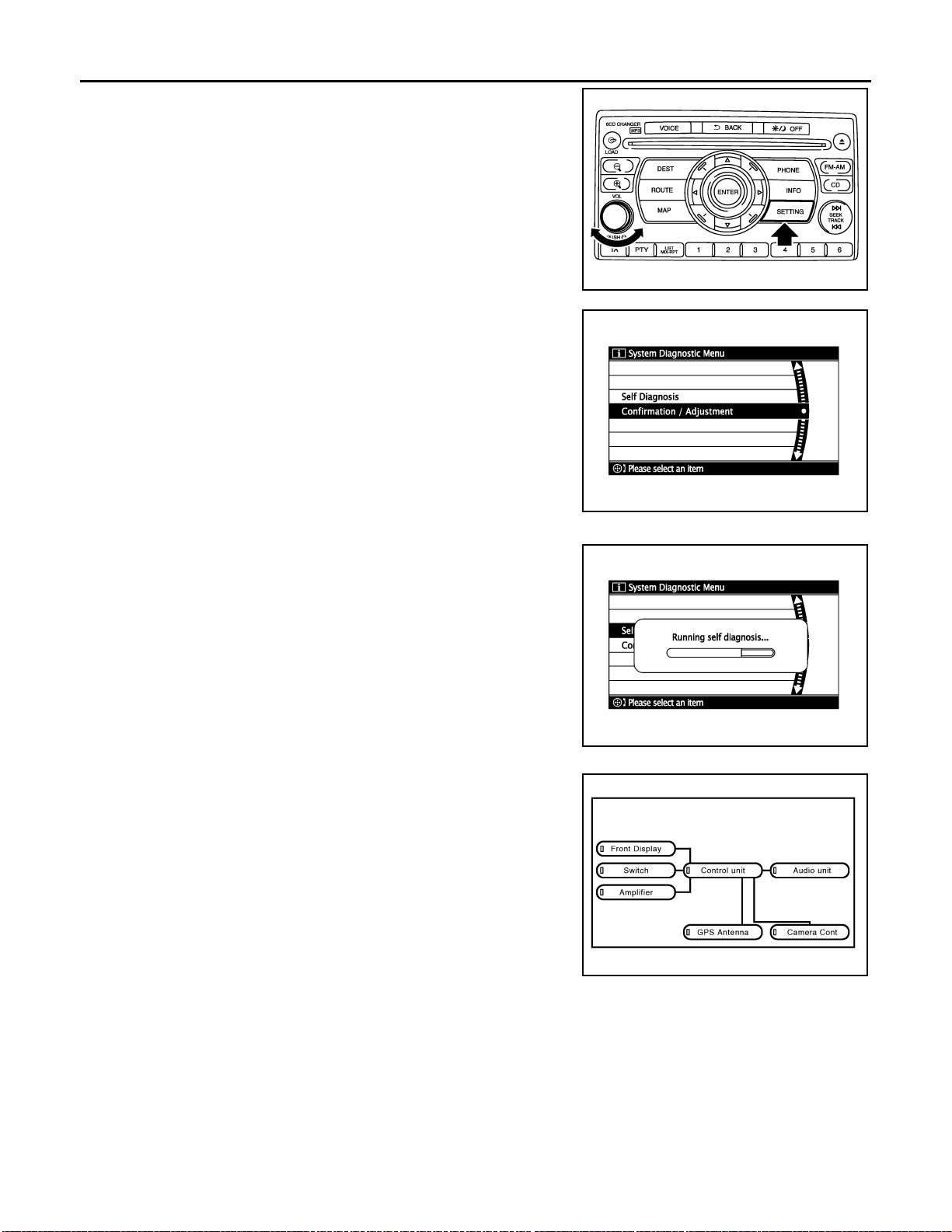
DIAGNOSIS SYSTEM (NAVI CONTROL UNIT)
< FUNCTION DIAGNOSIS >
3. Turn the volume control dial clockwise or counterclockwise for
40 clicks or more while pushing the “SETTING” button. (A short
beep will be heard when the self-diagnosis mode is started.)
• Shifting from current screen to previous screen is performed
by pushing “BACK” button.
4. The trouble diagnosis initial screen is displayed, and then the
items of “Self Diagnosis” and “Confirmation / Adjustment” can be
selected.
[AUDIO WITH NAVIGATION]
JSNIA0525GB
SKIB3961E
Self-diagnosis mode
1. Start the self-diagnosis function. Then select “Self Diagnosis”.
- Self-diagnosis subdivision screen is displayed, and the selfdiagnosis mode starts.
- The bar graph visible on the center of the self-diagnosis subdivision screen indicates progress of the trouble diagnosis.
SKIB3657E
2. Diagnosis results are displayed after the self-diagnosis is completed. The unit names and the connection lines are color-coded
according to the diagnostic results.
Diagnosis results Unit Connection
line
Normal Green Green
Connection malfunction Gray Yellow
DVD drive undiagnosed Gray Green
DVD-ROM and DVD-ROM
Yellow Green
drive malfunction
Unit malfunction
NOTE:
• Only the control unit (NAVI control unit) is displayed in red.
Note
Red Green
- The screen switch colors are determined according to the following order of priority: red > yellow > gray if
multiple errors occur at the same time for a single unit.
SKIB9021E
AV-64
Page 71
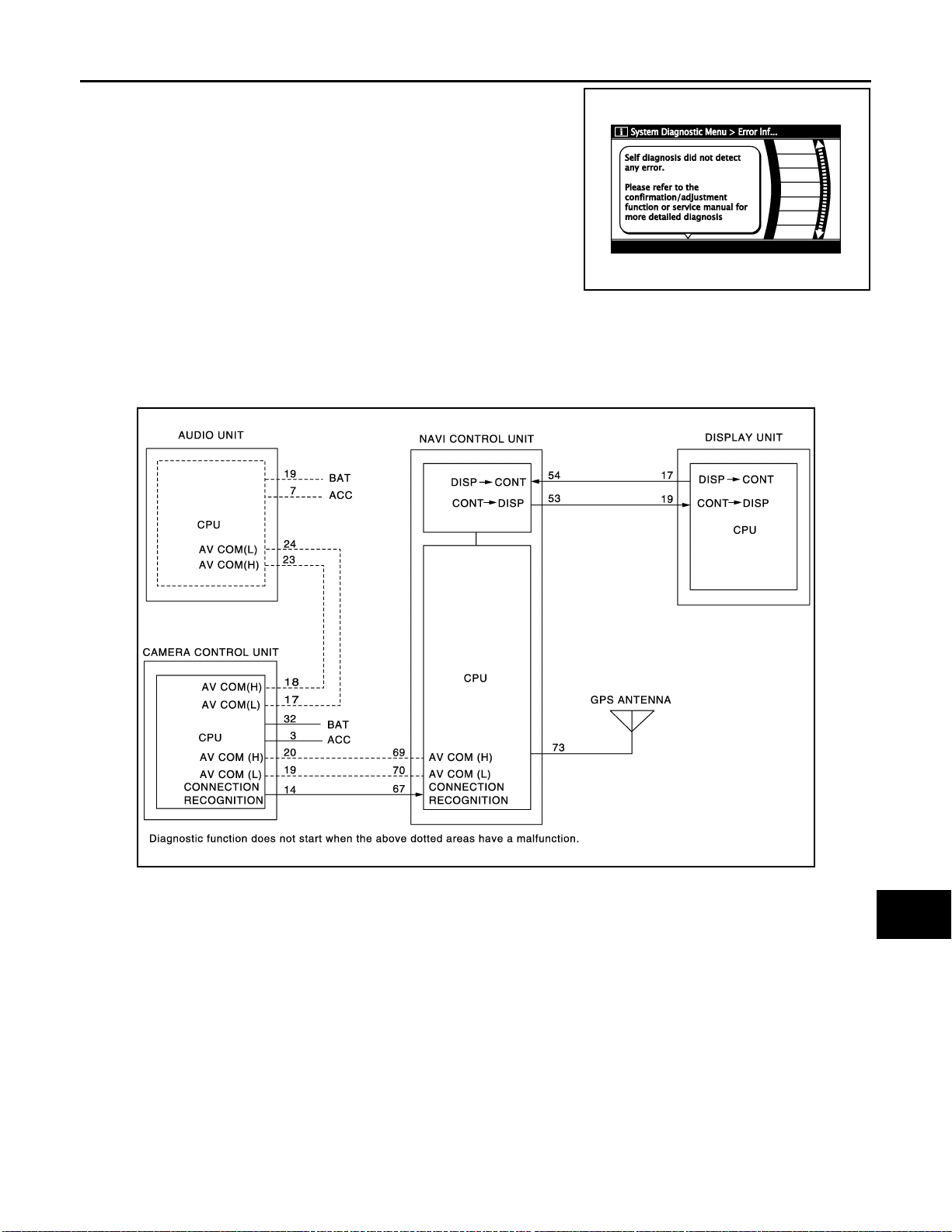
DIAGNOSIS SYSTEM (NAVI CONTROL UNIT)
< FUNCTION DIAGNOSIS >
- The comments of the self-diagnosis results can be viewed with a
component in the diagnosis result screen.
Detection range of self-diagnosis mode
• The self-diagnosis mode allows the technician to diagnose the connection in the communication line
between NAVI control unit and each unit and the internal operation of the NAVI control unit.
• Because the start condition of diagnosis function is a switch operation, the on board diagnosis function can-
not be started up if any malfunction is detected in a switch.
[AUDIO WITH NAVIGATION]
JPNIA0168GB
A
B
C
D
E
F
G
Self-diagnosis results
Check the applicable display at the following table, and then repair the malfunctioning parts.
Self-diagnosis result chart
JPNIA0247GB
H
I
J
K
L
M
AV
O
AV-65
P
Page 72
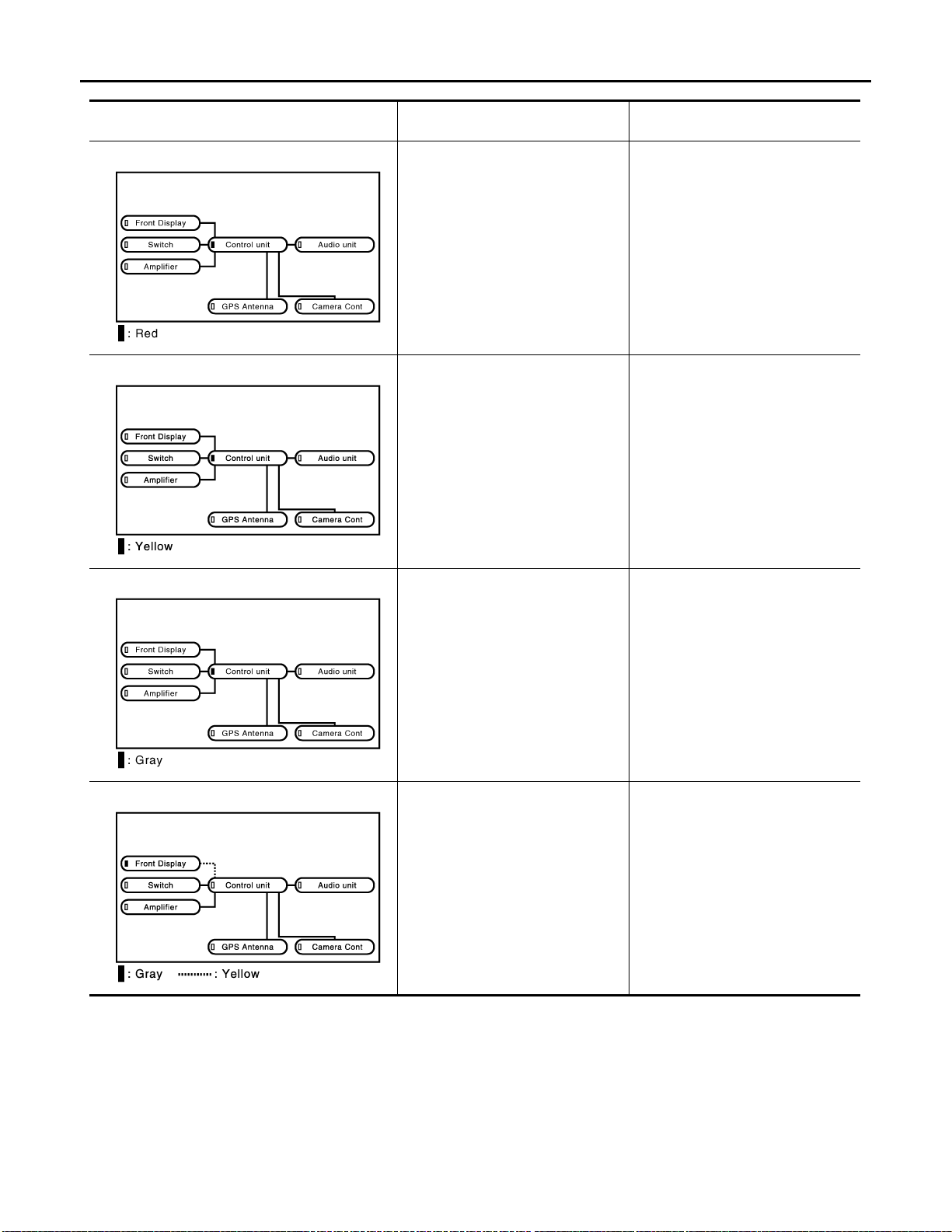
DIAGNOSIS SYSTEM (NAVI CONTROL UNIT)
< FUNCTION DIAGNOSIS >
[AUDIO WITH NAVIGATION]
Area with yellow connection lines Description
NAVI control unit malfunction is detected.
SKIB9022E
• Malfunction is detected on DVDROM drive pickup lens in NAVI control unit.
• There is dirt and damage on the
map disc.
JSNIA0380GB
Possible malfunction lo cation / Action
to take
NAVI control unit
•Map disc
•NAVI control unit
SKIB9024E
JSNIA0381GB
DVD-ROM not inserted is detected. Insert map disc
• Malfunction is detected on communication circuit between NAVI control unit and display unit.
• Malfunction is detected on communication signal between NAVI control unit and display unit.
Communication circuit between NAVI
control unit and display unit.
AV-66
Page 73
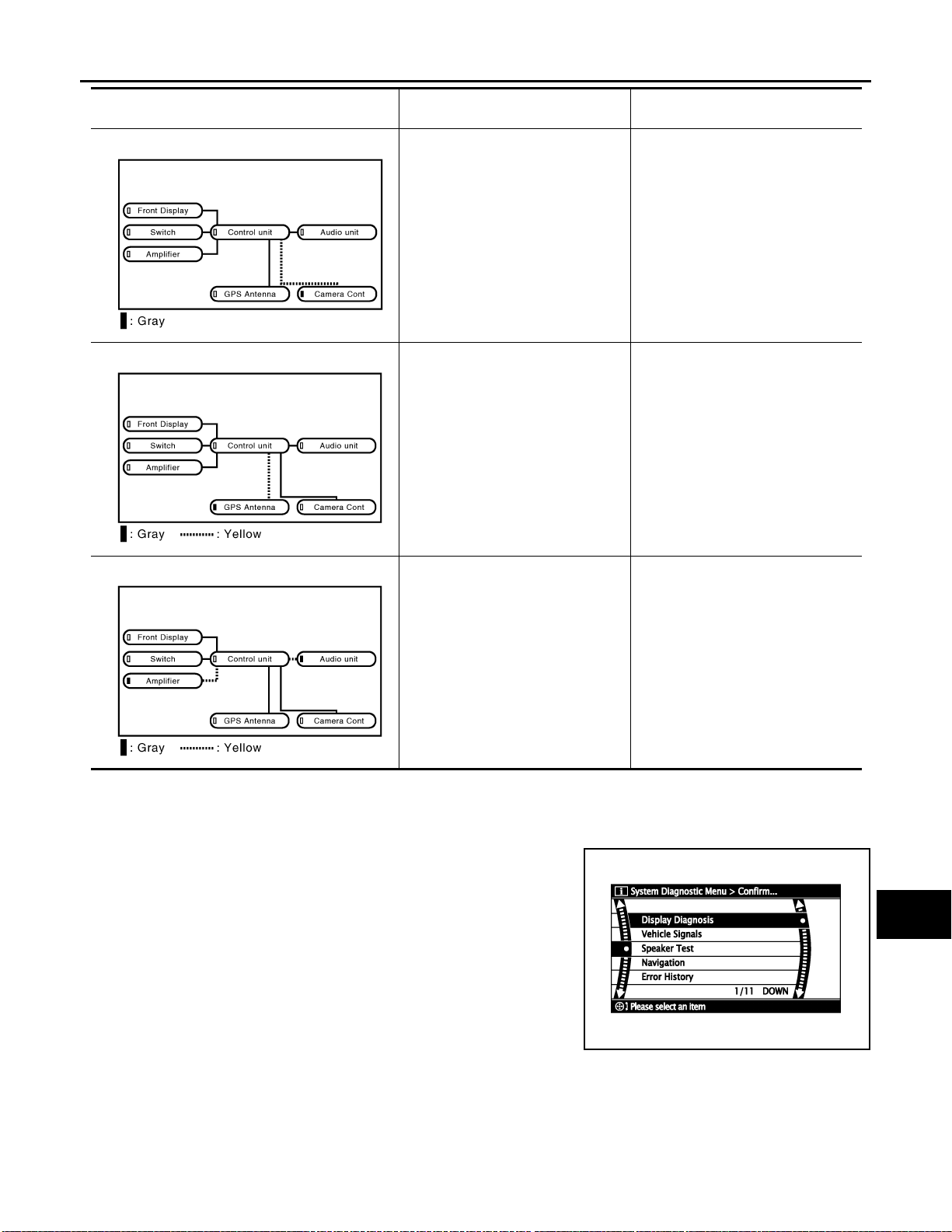
DIAGNOSIS SYSTEM (NAVI CONTROL UNIT)
< FUNCTION DIAGNOSIS >
[AUDIO WITH NAVIGATION]
Area with yellow connection lines Description
• A malfunction is detected in Camera-connection recognition signal
circuit.
• Camera control unit power supply
and ground circuit malfunction is
detected
• Malfunction is detected on communication signal between NAVI control unit and camera control unit.
JSNIA0445GB
GPS antenna connection malfuncti on
is detected.
SKIB9028E
Possible malfunction location / Action
to take
• Camera connection recognition signal circuit
• Camera control unit power supply
and ground circuit
•NAVI control unit
• Camera control unit
• GPS antenna
• GPS antenna feeder
A
B
C
D
E
F
G
H
Malfunction is detected on communication signal between NAVI control
unit and audio unit.
SKIB9025E
•NAVI control unit
• Audio unit
COMFIRMATON/ADJUSTMENT MODE
1. Start the diagnosis function and select “Confirmation / Adjustment”. The confirmation/adjustment mode
indicates where each item can be checked or adjusted.
2. Select each switch on the “Confirmation / Adjustment Mode”
screen to display the relevant trouble diagnosis screen. Press
the “BACK” switch to return to the initial “Confirmation / Adjustment Mode” screen.
SKIB4658E
I
J
K
L
M
AV
O
P
AV-67
Page 74
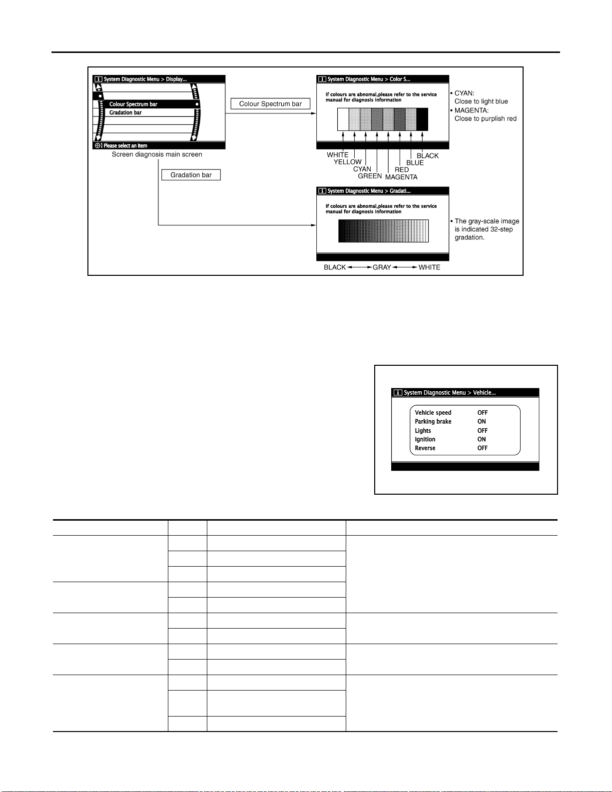
DIAGNOSIS SYSTEM (NAVI CONTROL UNIT)
< FUNCTION DIAGNOSIS >
Display Diagnosis
The tint of the color bar indication is as per the following list if RGB signal error is detected.
R (red) signal error : Light blue (Cyan) tint
G (green) signal error : Purple (Magenta) tint
B (blue) signal error : Yellow tint
[AUDIO WITH NAVIGATION]
JSNIA0531GB
Vehicle Signals
A comparison check can be made of each actual vehicle signal and
the signals recognized by the system.
Diagnosis item Display Vehicle status Remarks
ON Vehicle speed > 0 km/h (0 MPH)
Vehicle speed
Parking brake
Lights
Ignition
Reverse
OFF Vehicle speed = 0 km/h (0 MPH)
— Ignition switch ACC
ON Parking brake is applied.
OFF Parking brake is released.
ON Light switch ON
OFF Light switch OFF
ON Ignition switch ON
OFF Ignition switc h in ACC positio n
ON Selector lever in R position
Selector lever in any position othe r
than R
— Ignition switch ACC
Changes in indication may be delayed. This is normal.
Changes in indication may be delayed. This is normal.OFF
SKIB3663E
—
—
Speaker Test
AV-68
Page 75
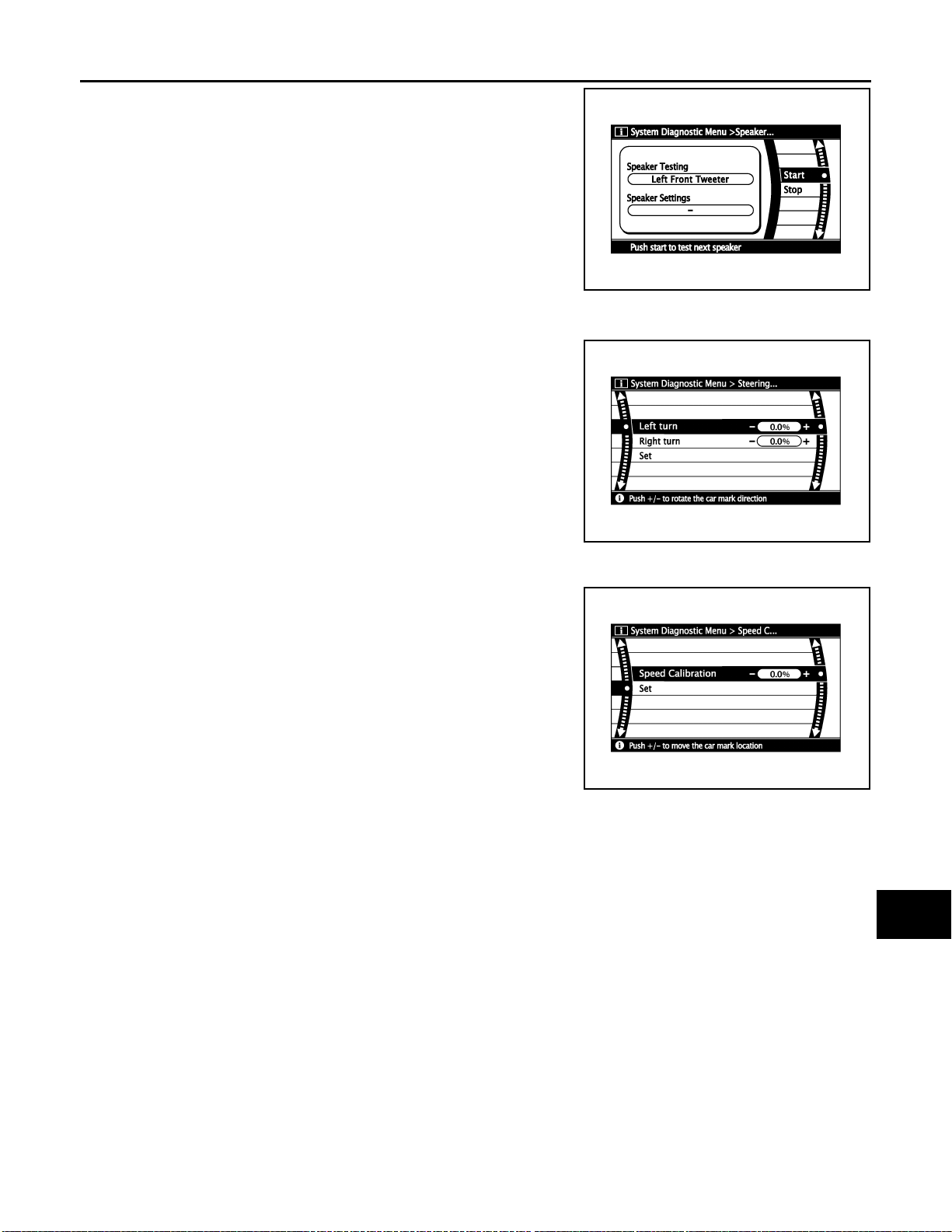
DIAGNOSIS SYSTEM (NAVI CONTROL UNIT)
< FUNCTION DIAGNOSIS >
Select “SPEAKER TEST” to display the Speaker Diagnosis screen.
Press “START and NEXT” to generate a test tone in a speaker.
Press “Start” to generate a test tone in the next speaker. Press
“Stop” to stop the test tones.
NOTE:
The frequency of test tone emitted from each speaker is as follows.
Tweeter : 3 kHz
Front door speaker : 300 Hz
Rear door speaker : 1 kHz
Navigation
STEERING ANGLE ADJUSTMENT
The steering angle output value detected with the gyroscope is
adjusted.
[AUDIO WITH NAVIGATION]
A
B
C
SKIB4686E
D
E
F
G
SKIB3684E
SPEED CALIBRATION
During normal driving, distance error caused by tire wear and tire
pressure change is automatically adjusted for by the automatic distance correction function. This function, on the other hand, is for
immediate adjustment, in cases such as driving with tire chain fitted
on tires.
SKIB3685E
ERROR HISTORY
The diagnostic results of “Self-diagnosis” determine if any malfunction occurred between selecting “Self-diagnosis” and displaying “Self-diagnostic Results”.
The trouble diagnosis result will be judged normal if an error occurred before the ignition switch was turned
ON and does not occur again until “Self-diagnosis” is completed. Therefore, errors in the past which cannot be
found by “Self-diagnosis”, must be found by checking the “Error record”.
The error history shows the error occurrence frequency in past. The frequency of occurrence is displayed by 2
types: the count down type and the count up type. Select either type according to the error item.
In “Error History” of models with NAVI, time and place that the selected error last occurred are displayed. Be
careful about the following.
• The correct date of occurrence may not be able to be displayed if there is a malfunction with the GPS
antenna circuit board in the NAVI control unit.
• Place of the error occurrence is represented by the position of the current location mark at the time an error
occurred. If current location mark has deviated from the correct position, then the place of the error occurrence cannot be located correctly .
H
I
J
K
L
M
AV
O
P
AV-69
Page 76
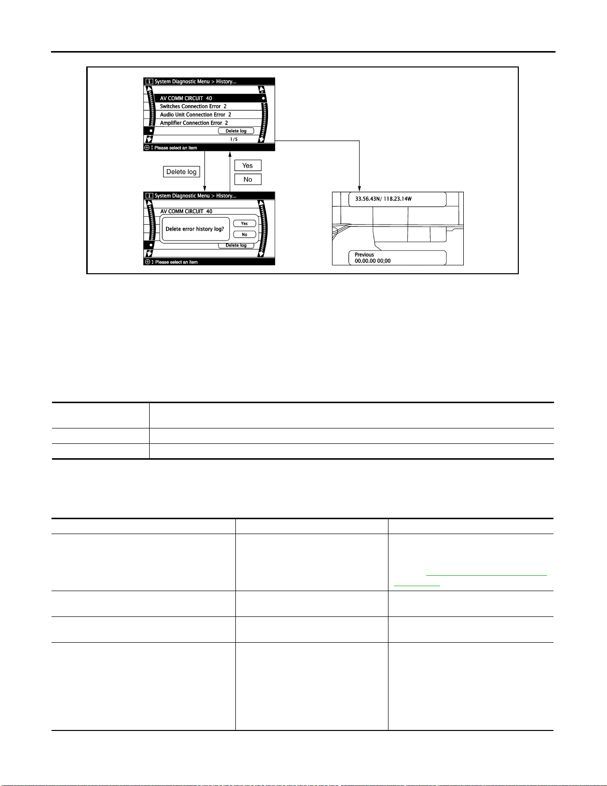
DIAGNOSIS SYSTEM (NAVI CONTROL UNIT)
< FUNCTION DIAGNOSIS >
Transition Screen
Count Down Type
• Set the counter to 40 when the error is detected. The counter decreases by 1 if the system is normal when
turning the ignition switch ON.
• The lower limit of the counter is 1. It can be reset to 0 by “Delete log” switch or CONSULT-III.
[AUDIO WITH NAVIGATION]
SKIB3687E
Count Up Type
• The counter increases 1 when the ignition switch is turned ON and the error is detected. The counter does
not decrease even if it is normal when the ignition switch is turned ON the next time.
• The upper limit of the counter is 50. 51 or more is displayed as 50. It can be reset to 0 by “Delete log” switch
or CONSULT-III.
Display type of occur-
rence frequency
Count down type CAN_COMM_CIRCUIT, CONTROL UNIT (CAN), AV COMM CIRCUIT, CONTROL UNIT (AV)
Count up type Other than the above
Error Item
Error history display item
• Some error items may be displayed simultaneously according to the cause. The detection of the cause can
be performed by the combination of display items if some error items are displayed simultaneously.
Error item Description Possible cause/Action to take
Perform the diagnosis using CONSUL T -III,
and then repair the malfunctioning parts
based on diagnostic results.
Refer to AV-74, "
(MULTI AV)".
NAVI control unit
NAVI control unit
• Audio unit power supply and ground circuit
• Communication circuit between audio
unit and camera control unit
•NAVI control unit
• Audio unit
CONSULT - III Function
CAN_COMM_CIRCUIT
CONTROL UNIT (CAN)
CONTROL UNIT (AV)
• AV COMM CIRCUIT
• Switches Connection Error
• Audio Unit Connection Error
• Amplifier Connection Error
• RDS-TMC Error
CAN communication malfunction is detected.
CAN initial diagnosis malfunction is detected.
AV communication circuit initial diagnosis malfunction is detected.
• Audio unit power supply and ground
circuit malfunction is detected.
• Malfun ction is d etect ed o n commu nication circuit between audio unit and
camera control unit.
• Malfun ction is d etect ed o n commu nication signal between audio unit and
NAVI control unit.
AV-70
Page 77

DIAGNOSIS SYSTEM (NAVI CONTROL UNIT)
< FUNCTION DIAGNOSIS >
[AUDIO WITH NAVIGATION]
Error item Description Possible cause/Action to take
• AV COMM CIRCUIT
• Switches Connection Error
• Audio Unit Connection Error
• Amplifier Connection Error
• RDS-TMC Error
• Rear view Camera Connection Error
• AV COMM CIRCUIT
• Rear view Camera Connection Error
Front Display Connection Error
GPS Antenna Error
Camera Control Unit Connection Error
FLASH-ROM Error Of Control Unit
Connection Of Gyro
GPS Communication Error
GPS ROM Error
GPS RAM Error
GPS RTC Error
DVD-ROM Communication Error
DVD-ROM Read Error
DVD-ROM Disc Error
DVD-ROM Mechanism not Detected
DVD-ROM Mechanism Error
DVD-ROM Focus Error
DVD-ROM TOC Error
DVD-ROM Seek Error
DVD-ROM Error Correction Error
DVD-ROM Data Transfer Error
DVD-ROM Data Error
DVD-ROM Time-out
DVD-ROM Loading / Eject Error
CAN Controller Memory Error
Bluetooth Module Connection Error
• Malfunction is detected on communication circuit between camera control unit and NAVI control unit.
• Camera control unit power supply
and ground circuit malfunction is detected.
• Malfunction is detected on communication signal between camera control unit and NAVI control unit.
• Display unit power supply and
ground circuit malfunction is detected.
• Malfunction is detected on communication circuit between display unit
and NAVI control unit.
• Malfunction is detected on communication signal between display unit
and NAVI control unit.
GPS antenna connection malfunction
is detected.
Camera and connection recognition
signal circuit malfunction is detected.
NAVI control unit malfunction is detected.
NAVI control unit malfunction is detected.
GPS malfunction is detected.
• Malfunction is detected on DVDROM drive pickup lens in NAVI control unit.
• There is dirt and damage on the map
disc.
NAVI control unit malfunction is detected.
Communication circuit between camera
control unit and NAVI control unit
• Camera control unit power supply and
ground circuit
•NAVI control unit
• Camera control unit
• Display unit power supply and ground
circuit
• Communication circuit between display
unit and NAVI control unit
• GPS antenna feeder
• GPS antenna
Camera-connection recognition signal circuit
NAVI control unit
NAVI control unit
Intermittent malfunction caused by strong
radio interference may be detected if the
symptoms such as the GPS receipt malfunction occur.
Replace NAVI control unit if the malfunction always occurs.
•Map disc
•NAVI control unit
NAVI control unit
A
B
C
D
E
F
G
H
I
J
K
L
M
AV
O
P
Vehicle CAN Diagnosis
AV-71
Page 78
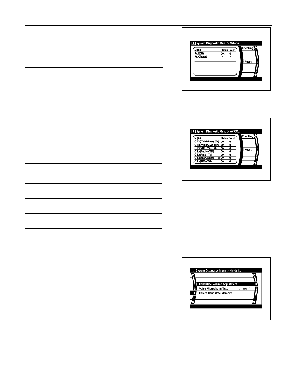
DIAGNOSIS SYSTEM (NAVI CONTROL UNIT)
< FUNCTION DIAGNOSIS >
• CAN communication status and error counter is displayed.
• Error counter displays 0 if any malfunction is not detected in the
past. It displays 40 if the malfunction is detected. It displays 39
when turning the ignition switch ON and it is normal. The lower
limit of the counter is 1.
• The error counter displays 0 if it resets.
[AUDIO WITH NAVIGATION]
Items Display (Current)
Rx (ECM) OK / ??? 0 – 40
Rx (Cluster) — —
NOTE:
“???” indicates UNKWN.
Malfunction counter
(Past)
AV COMM Diagnosis
• Displays the communication status between NAVI control unit
(master unit) and each unit.
• The error counter displays 0 if any malfunction was not detected in
the past. It displays 40 if the malfunction is detected. It displays 39
when turning the ignition switch ON and it is normal. The lower
limit of the counter is 1.
• The error counter is erased if it resets.
Items
C Tx(ITM–PrimarySW) OK / ??? 0 – 40
C Rx(PrimarySW–ITM) OK / ??? 0 – 40
C Rx(STRG SW–ITM) OK / ??? 0 – 40
C Rx (Audio–ITM) OK / ??? 0 – 40
C Rx(Amp–ITM) OK / ??? 0 – 40
C Rx(RearCamera–ITM) OK / ??? 0 – 40
C Rx(RDS–ITM) OK / ??? 0 – 40
ITM: NAVI control unit
NOTE:
“???” indicates UNKWN.
Status
(Current)
Counter
(Past)
JSNIA0448GB
JSNIA0446GB
Handsfree Phone
The hands-free phone reception volume adjustment, microphone
and speaker test, and memory erase functions are also available.
Camera Cont.
The two functions of “Connection Confirmation” and “Adjust offset of rear view camera” are available.
CONNECTION CONFIRAMATION
AV-72
SKIB3668E
Page 79
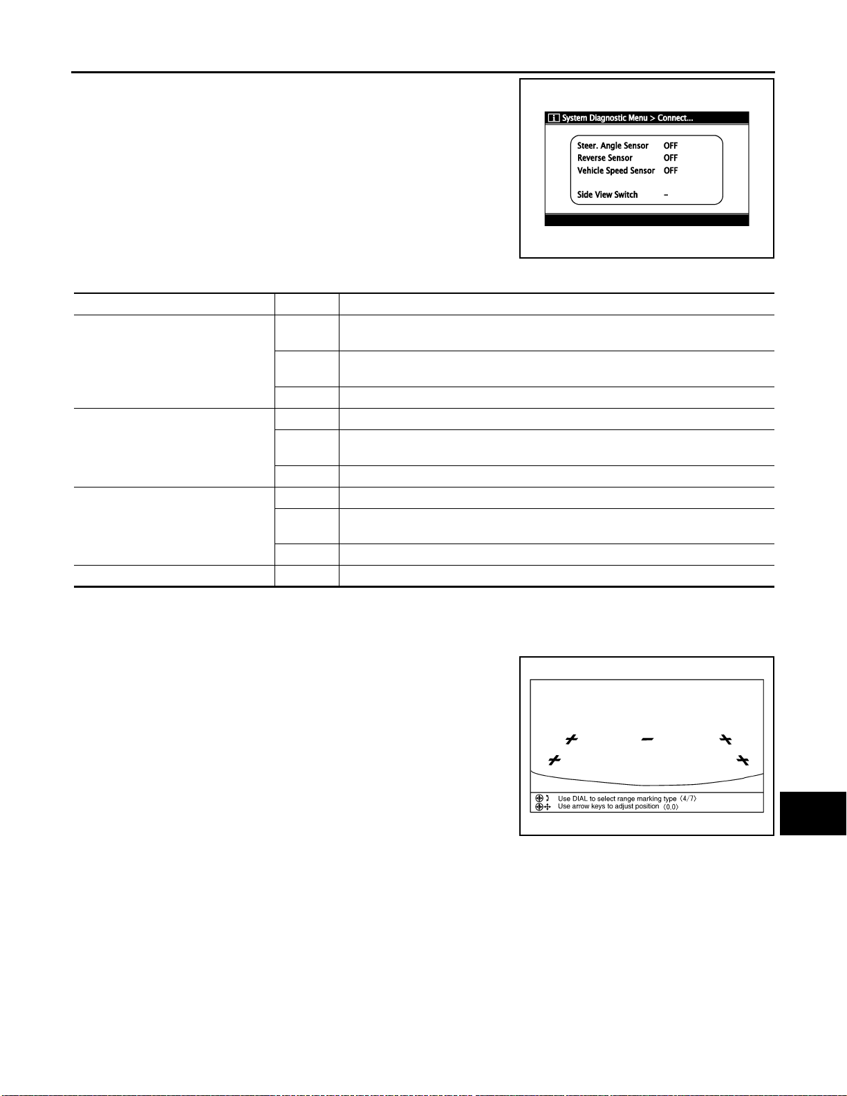
DIAGNOSIS SYSTEM (NAVI CONTROL UNIT)
< FUNCTION DIAGNOSIS >
The steering angle sensor, reverse signal and vehicle speed sensor
can be inspected.
Diagnosis item Display Vehicle status
ON
Steer. Angle Sensor
Reverse Sensor
Vehicle Speed Sensor
Side View Switch — —
OFF
— Malfunction detected in camera-connection recognition signal
ON Selector lever is in “R” with ignition switch ON.
OFF
— Malfunction detected in camera-connection recognition signal
ON Vehicle speed is more than 0 km/h with ignition switch ON
OFF
— Malfunction detected in camera-connection recognition signal
When steering the vehicle with ignition switch ON (remains ON until connection
mode is stopped when it is turned ON)
• Ignition switch at ACC
• No steering with ignition switch ON
• Ignition switch at ACC
• Selector lever is in position other than “R” with ignition switch ON.
• Ignition switch at ACC
• Vehicle speed is 0 km/h with ignition switch ON
ADJUST OFFSET OF REAR VIEW CAMERA
Use this mode to adjust the guide line display position of the rear view monitor if necessary after removing the
rear view monitor camera.
NOTE:
The number on the top left of the screen has no relation to diagnosis
and adjustment.
[AUDIO WITH NAVIGATION]
JSNIA0447GB
A
B
C
D
E
F
G
H
I
J
K
Bluetooth
Confirmation/Change Passkey
L
M
AV
SKIB3689E
O
P
AV-73
Page 80
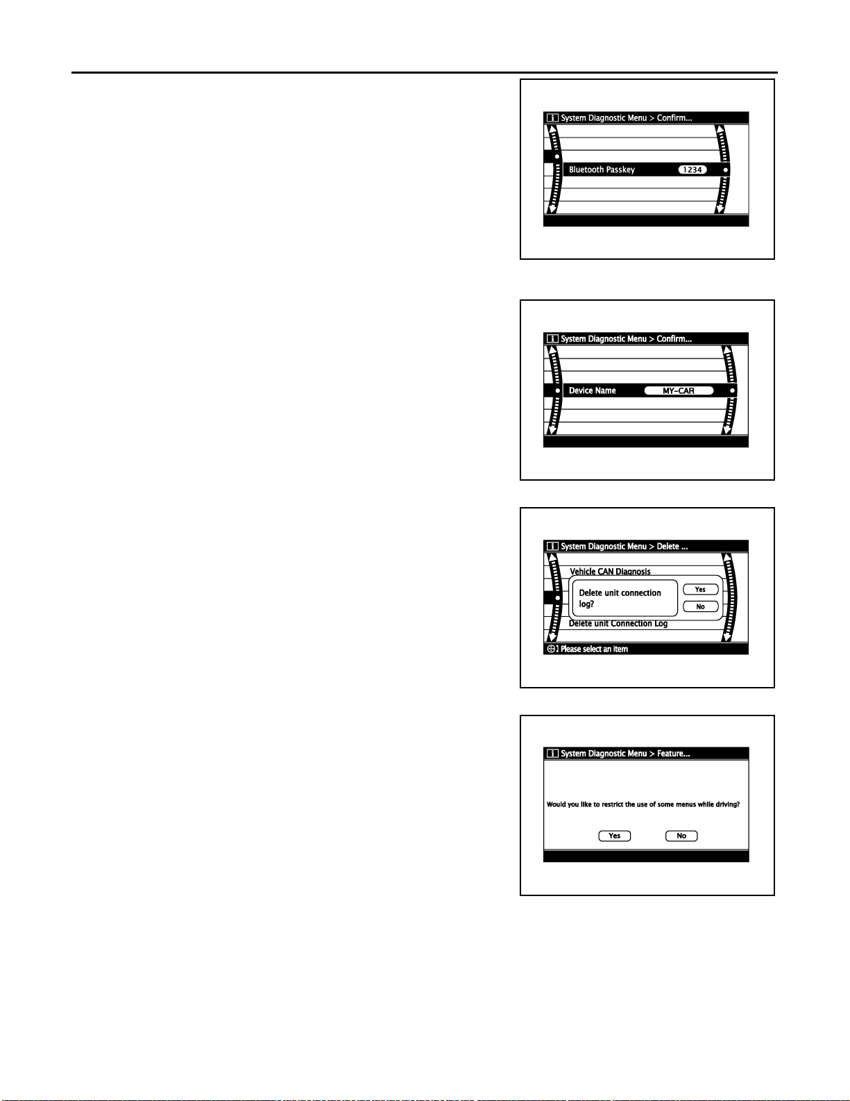
DIAGNOSIS SYSTEM (NAVI CONTROL UNIT)
< FUNCTION DIAGNOSIS >
• The passkey of Bluetooth can be confirmed and changed.
• The passkey can be changed by four digits within 0 to 9.
Confirmation/Change Device Name
• The device name of Bluetooth can be confirmed and changed.
• The device name can be changed by sixteen digits within A to Z
(small character can be used) and - (hyphen).
[AUDIO WITH NAVIGATION]
SKIB3669E
Delete Unit Connection Log
Deletes any unit connection records and error records from the NA VI
control unit memory. (Clear the records of the unit that has been
removed.)
Feature Restriction Setting
Operations of navigation system that are performed while driving
can be restricted by using this function.
CAUTION:
Once operational restrictions are imposed, they can not be cancelled even when the software is updated or the languageswitching program is loaded.
JSNIA0526GB
JPNIA0172GB
JSNIA0345GB
CONSULT - III Function (MULTI AV) INFOID:0000000001092947
CONSULT-III functions
CONSULT- III performs the following functions via the communication with the NAVI control unit.
AV-74
Page 81
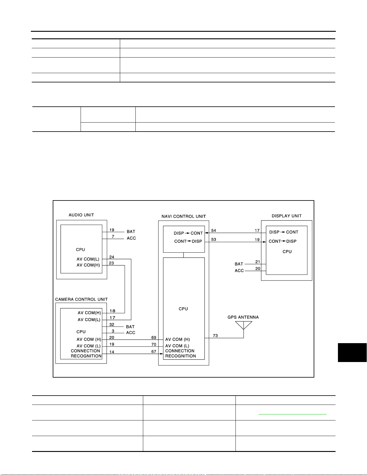
DIAGNOSIS SYSTEM (NAVI CONTROL UNIT)
< FUNCTION DIAGNOSIS >
[AUDIO WITH NAVIGATION]
Diagnosis mode Description
Ecu Identification The part number of NAVI control unit can be checked.
Self Diagnostic Result
Data Monitor The diagnosis of vehicle signal that is input to the NAVI control unit can be performed.
Performs a diagnosis on the NAVI control unit and a connection diagnosis for the communication circuit of the Multi AV system, and displays the current and past malfunctions collectively.
AV COMMUNICATION
When “A V communication” of “CAN Diag Support Monitor” i s selected, the following function will be performed.
Displays the communication st atu s from NAVI control unit to each unit as well as the error counter.
AV communication
AV&NAVI C/U
AUDIO Displays the NAVI control unit communication status and the error counter.
ECU IDENTIFICATION
The part number of NAVI control unit is displayed.
SELF DIAGNOSIS RESULT
• In CONSULT-III self-diagnosis, self-diagnosis results and error history are displayed collectively.
• The current malfunction indicates “CRNT”. The past malfunction indicates “PAST”.
• The timing is displayed as “0” if any of the error codes [U1000], [U1010], [U1300] and [U1310] is detected.
The counter increases by 1 if the condition is normal at the next ignition switch ON cycle.
Self-diagnosis detection range
A
B
C
D
E
F
G
H
Self-diagnosis results display item
Error item Description Possible cause/Action to take
CAN COMM CIRCUIT[U1000]
CONTROL UNIT (CAN) [U1010]
CONTROL UNIT (AV) [U1310]
CAN communication malfunctio n is detected.
CAN initial diagnosis malfunction is detected.
AV communication circuit initial diagnosis malfunction is detected.
Refer to AV-78, "
NAVI control unit
NAVI control unit
JPNIA0248GB
Diagnosis Procedure".
I
J
K
L
M
AV
O
P
AV-75
Page 82

DIAGNOSIS SYSTEM (NAVI CONTROL UNIT)
< FUNCTION DIAGNOSIS >
Error item Description Possible cause/Action to take
• AV COMM CIRCUIT [U1300]
• SWITCH CONN [U1240]
• AUDIO H/U CONN [U1249]
• AMP CONN [U124E]
• RDS CONN [U124F]
• AV COMM CIRCUIT [U1300]
• SWITCH CONN [U1240]
• AUDIO H/U CONN [U1249]
• AMP CONN [U124E]
• RDS CONN [U124F]
• REAR-CAMERA LAN CONN [U1252]
• AV COMM CIRCUIT [U1300]
• REAR-CAMERA LAN CONN [U1252]
FRONT DISP CONN [U1243]
GPS ANTENNA CONN [U1244]
CAMERA CONT. CONN [U1250]
Control Unit FLASH-ROM [U1200]
Gyro NO CONN [U1201]
GPS COMM [U1204]
GPS ROM [U1205]
GPS RAM [U1206]
GPS RTC [U1207]
• Audio unit power supply and ground
circuit malfunction is detected.
• Malfun ction is d etect ed o n commu nication circuit between audio unit and
camera control unit.
• Malfun ction is d etect ed o n commu nication signal between audio unit and
NAVI control unit.
Malfunction is detected on communication circuit between camera control unit
and NAVI control unit.
• Camera control unit power supply
and ground circuit malfunction is detected.
• Malfun ction is d etect ed o n commu nication signal between camera control unit and NAVI control unit.
• Display unit power supply and
ground circuit malfunction is detected.
• Malfun ction is d etect ed o n commu nication circuit between display unit
and NAVI control unit.
• Malfun ction is d etect ed o n commu nication signal between display unit
and NAVI control unit.
GPS antenna connection malfunction
is detected.
Camera and connection recognitio n
signal circuit malfunction is detected.
NAVI control unit malfunction is detected.
NAVI control unit malfunction is detected.
GPS malfunction is detected.
[AUDIO WITH NAVIGATION]
• Audio unit power supply and ground circuit
• Communication circuit between audio
unit and camera control unit
•NAVI control unit
• Audio unit
Communication circuit between cam era
control unit and NAVI control unit
• Camera control unit power supply and
ground circuit
•NAVI control unit
• Camera control unit
• Display unit power supply and ground
circuit
• Communication circuit between display
unit and NAVI control unit
• GPS antenna feeder
• GPS antenna
Camera-connection recognition signal circuit
NAVI control unit
NAVI control unit
Intermittent malfunction caused by strong
radio interference may be detected if the
symptoms such as the GPS receipt malfunction occur.
Replace NAVI control unit if the malfunction always occurs.
AV-76
Page 83
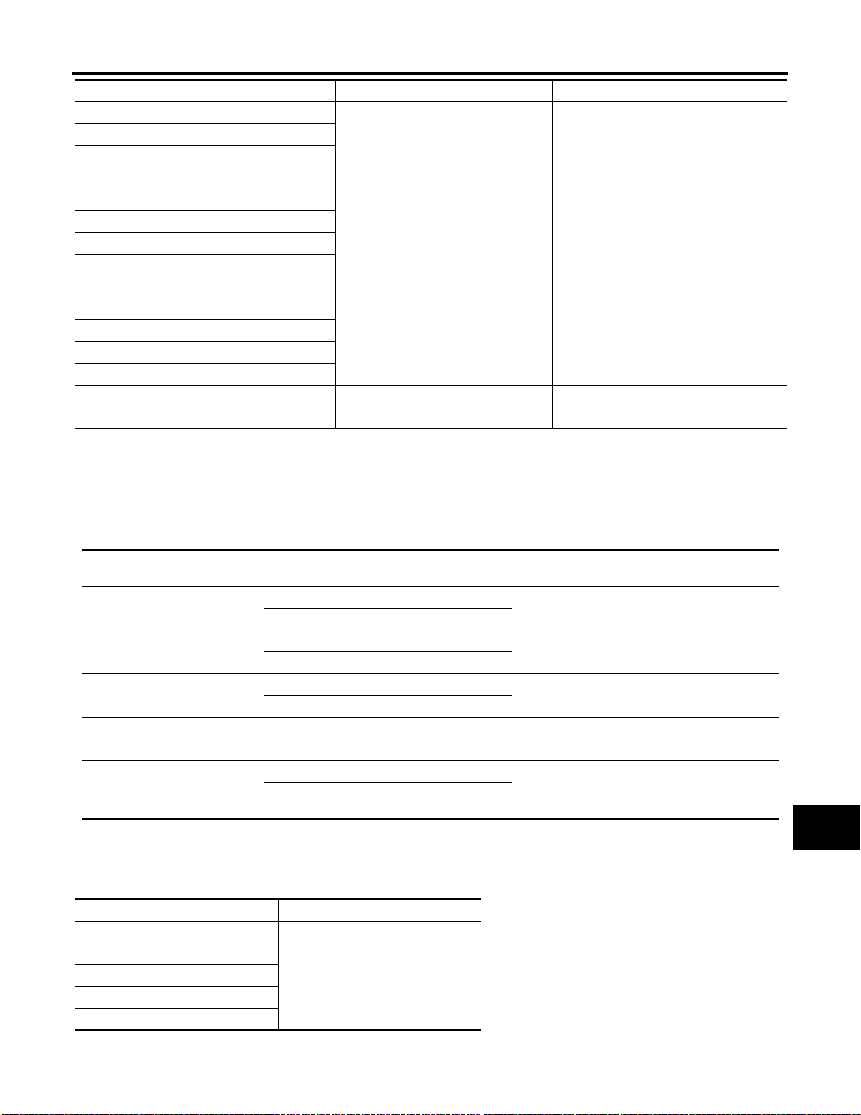
DIAGNOSIS SYSTEM (NAVI CONTROL UNIT)
< FUNCTION DIAGNOSIS >
[AUDIO WITH NAVIGATION]
Error item Description Possible cause/Action to take
DVD-ROM COMM [U1208]
DVD-ROM READ [U1209]
DVD-ROM DISC [U120A]
DVD-ROM MECHA DETECT [U120C]
DVD-ROM DRIVE MECHA [U120D]
DVD-ROM FOCUS [U120E]
DVD-ROM TOC [U120F]
DVD-ROM SEEK [U1210]
DVD-ROM ERR CORRECTION [U1211]
DVD-ROM DATA FORWARD [U1212]
DVD-ROM DATA [U1213]
DVD-ROM TIMEOUT [U1214]
DVD-ROM LOAD [U1215]
CAN CONT [U1216]
BLUETOOTH CONN [U1217]
• Malfunction is detected on DVDROM drive pickup lens in NAVI control unit.
• There is dirt and damage on the map
disc.
NAVI control unit malfunction is detected.
•Map disc
•NAVI control unit
NAVI control unit
DATA MONITOR
ALL SIGNALS
• Displays the status of the following vehicle signals inputted to the NAVI control unit.
• For each signal, actual signal can be compared with the condition recognized on the system.
A
B
C
D
E
F
G
H
Display Item
VHCL SPD SIG
PKB SIG
ILLUM SIG
IGN SIG
REV SIG
Dis-
play
ON Vehicle speed >0 km/h (0 MPH)
OFF Vehicle speed =0 km/h (0 MPH)
ON Parking brake is applied.
OFF Parking brake is released.
ON Lighting switch ON
OFF Lighting switch OFF
ON Ignition switch ON
OFF Ignition switch in ACC position
ON Selector lever in R position
Selector lever in any position other
OFF
than R
Vehicle status Remarks
Changes in indication may be delayed. This is
normal.
Changes in indication may be delayed. This is
normal.
—
—
Changes in indication may be delayed. This is
normal.
SELECTION FROM MENU
Allows the technician to select which vehicle signals should be displayed and displays the status of the
selected vehicle signals.
Item to be selected Description
VHCL SPD SIG
PKB SIG
ILLUM SIG
IGN SIG
REV SIG
The same as when “ALL SIGNALS”
is selected.
I
J
K
L
M
AV
O
P
AV-77
Page 84

U1000 CAN COMM CIRCUIT
< COMPONENT DIAGNOSIS >
[AUDIO WITH NAVIGATION]
COMPONENT DIAGNOSIS
U1000 CAN COMM CIRCUIT
Description INFOID:0000000001092949
CAN (Controller Area Network) is a serial communication line for real time application. It is an on-vehicle multiplex communication line with high data communication speed and excellent error detection ability. Many electronic control units are equipped onto a vehicle, and each control unit shares information and links with other
control units during operation (not independent). In CAN communication, control units are connected with 2
communication lines (CAN-H line, CAN-L line) allowing a high rate of information transmission with less wiring.
Each control unit transmits/receives data but selectively reads required data only.
CAN Communication Signal Chart. Refer to LAN-25, "
DTC Logic INFOID:0000000001092950
DTC DETECTION LOGIC
CAN Communication Signal Chart".
DTC
U1000
Display contents of CON-
SULT-III
CAN COMM CIRCUIT
[U1000]
Diagnostic item is detected when... Probable malfunction location
When NAVI control unit is not transmit or receive CAN communication signal for 2 seconds or more.
CAN communication system
Diagnosis Procedure INFOID:0000000001092951
1.PERFORM SELF DIAGNOSTIC
1. Turn ignition switch ON and wait for 2 seconds or more.
2. Check “Self Diagnostic Result” of “MULTI AV”.
Is
“CAN COMM CIRCUIT” displayed?
YES >> Refer to “LAN system”. Refer to LAN-13, "Trouble Diagnosis Flow Chart".
NO >> Refer to GI section. Refer to GI-39, "
Intermittent Incident".
AV-78
Page 85
< COMPONENT DIAGNOSIS >
U1010 CONTROL UNIT (CAN)
[AUDIO WITH NAVIGATION]
U1010 CONTROL UNIT (CAN)
Description INFOID:0000000001092952
Initial diagnosis of NA VI control unit.
DTC Logic INFOID:0000000001092953
DTC DETECTION LOGIC
DTC
U1010
Display contents of CON-
SULT-III
CONTROL UNIT (CAN)
[U1010]
Diagnostic item is detected when... Probable malfunction location
CAN initial diagnosis malfunction is detected. NAVI control unit
Diagnosis Procedure INFOID:0000000001092954
1.REPLACE NAVI CONTROL UNIT
Replace NAVI control unit when DTC U1010 is detected.
>> INSPECTION END
A
B
C
D
E
F
G
H
AV
I
J
K
L
M
O
P
AV-79
Page 86

U1310 NAVI CONTROL UNIT
< COMPONENT DIAGNOSIS >
[AUDIO WITH NAVIGATION]
U1310 NAVI CONTROL UNIT
Description INFOID:0000000001092955
Replace the NA VI control unit if this DTC is displayed. Refer to AV-257, "Exploded View".
Part name Description
• Map data can be read from the Map DVD-ROM by installing Map DVD-ROM.
• It is the master unit of the MULTI A V system, and it is connected to each control
unit by means of communication. It operates each system according to communication signals from the NAVI control unit.
• The NAVI control unit includes the audio, hands-free phone, navigation, and
NA VI CONTORL UNIT
DTC Logic INFOID:0000000001092956
vehicle information functions.
• The NAVI control unit displays the maintenance information while receiving
data signal through CAN communi cation from combination meter.
• It inputs the illumination signals that are required for the display dimming control.
• It inputs the signals for driving status recognition (vehicle speed, reverse and
parking brake).
DTC
U1310
Display contents of
CONSULT-III
CONTROL UNIT (AV)
[U1310]
DTC Detection Condition Action to take
AV communication circuit initial diagnosis malfunction is
detected.
Replace NAVI control unit.
AV-80
Page 87
< COMPONENT DIAGNOSIS >
U1200 NAVI CONTROL UNIT
[AUDIO WITH NAVIGATION]
U1200 NAVI CONTROL UNIT
Description INFOID:0000000001115047
Replace the NAVI control unit if this DTC is displayed. Refer to AV-257, "Exploded View".
Part name Description
• Map data can be read from the Map DVD-ROM by installing Map DVD-ROM.
• It is the master unit of the MULTI A V system, and it is connected to each control
unit by means of communication. It operates each system according to communication signals from the NAVI control unit.
• The NAVI control unit includes the audio, hands-free phone, navigation, and
NAVI CONTORL UNIT
DTC Logic INFOID:0000000001092958
DTC
U1200
Display contents of
CONSULT-III
Cont Unit
FLASH- ROM
[U1200]
An internal malfunction is detected in NAVI control unit
(FLASH-ROM).
vehicle information functions.
• The NAVI control unit displays the maintenance information while receiving
data signal through CAN communication from combination meter.
• It inputs the illumination signals that are required for the display dimming control.
• It inputs the signals for driving status recognition (vehicle speed, reverse and
parking brake).
DTC Detection Condition Action to take
Replace NAVI control unit.
A
B
C
D
E
F
G
H
AV
I
J
K
L
M
O
P
AV-81
Page 88

U1201 NAVI CONTROL UNIT
< COMPONENT DIAGNOSIS >
[AUDIO WITH NAVIGATION]
U1201 NAVI CONTROL UNIT
Description INFOID:0000000001115048
Replace the NA VI control unit if this DTC is displayed. Refer to AV-257, "Exploded View".
Part name Description
• Map data can be read from the Map DVD-ROM by installing Map DVD-ROM.
• It is the master unit of the MULTI A V system, and it is connected to each control
unit by means of communication. It operates each system according to communication signals from the NAVI control unit.
• The NAVI control unit includes the audio, hands-free phone, navigation, and
NA VI CONTORL UNIT
DTC Logic INFOID:0000000001092960
vehicle information functions.
• The NAVI control unit displays the maintenance information while receiving
data signal through CAN communi cation from combination meter.
• It inputs the illumination signals that are required for the display dimming control.
• It inputs the signals for driving status recognition (vehicle speed, reverse and
parking brake).
DTC
U1201
Display contents of
CONSULT-III
GYRO NO CONN
[U1201]
DTC Detection Condition Action to take
Internal malfunction of NAVI control unit (gyrocompass
disconnection) is detected.
Replace NAVI control unit.
AV-82
Page 89
< COMPONENT DIAGNOSIS >
U1216 NAVI CONTROL UNIT
[AUDIO WITH NAVIGATION]
U1216 NAVI CONTROL UNIT
Description INFOID:0000000001115049
Replace the NAVI control unit if this DTC is displayed. Refer to AV-257, "Exploded View".
Part name Description
• Map data can be read from the Map DVD-ROM by installing Map DVD-ROM.
• It is the master unit of the MULTI A V system, and it is connected to each control
unit by means of communication. It operates each system according to communication signals from the NAVI control unit.
• The NAVI control unit includes the audio, hands-free phone, navigation, and
NAVI CONTORL UNIT
DTC Logic INFOID:0000000001092962
DTC
U1216
Display contents of
CONSULT-III
CAN CONT
[U1216]
Internal malfunction of NAVI control unit (CAN controller)
is detected.
vehicle information functions.
• The NAVI control unit displays the maintenance information while receiving
data signal through CAN communication from combination meter.
• It inputs the illumination signals that are required for the display dimming control.
• It inputs the signals for driving status recognition (vehicle speed, reverse and
parking brake).
DTC Detection Condition Action to take
Replace NAVI control unit.
A
B
C
D
E
F
G
H
AV
I
J
K
L
M
O
P
AV-83
Page 90

U1217 NAVI CONTROL UNIT
< COMPONENT DIAGNOSIS >
[AUDIO WITH NAVIGATION]
U1217 NAVI CONTROL UNIT
Description INFOID:0000000001115050
Replace the NA VI control unit if this DTC is displayed. Refer to AV-257, "Exploded View".
Part name Description
• Map data can be read from the Map DVD-ROM by installing Map DVD-ROM.
• It is the master unit of the MULTI A V system, and it is connected to each control
unit by means of communication. It operates each system according to communication signals from the NAVI control unit.
• The NAVI control unit includes the audio, hands-free phone, navigation, and
NA VI CONTORL UNIT
DTC Logic INFOID:0000000001092964
vehicle information functions.
• The NAVI control unit displays the maintenance information while receiving
data signal through CAN communi cation from combination meter.
• It inputs the illumination signals that are required for the display dimming control.
• It inputs the signals for driving status recognition (vehicle speed, reverse and
parking brake).
DTC
U1217
Display contents of
CONSULT-III
BLUETOOTH MODULE
CONN
[U1217]
DTC Detection Condition Action to take
Internal malfunction of NAVI control unit (Bluetooth module connection malfunction) is detected.
Replace NAVI control unit.
AV-84
Page 91
< COMPONENT DIAGNOSIS >
U1204 GPS
[AUDIO WITH NAVIGATION]
U1204 GPS
Description INFOID:0000000001092965
An intermittent error caused by strong radio interference may be detected unless any symptoms (GPS reception error, etc.) occur. Replace the NAVI control unit if the malfunction occurs constantly. Refer to AV-257,
"Exploded View".
Part name Description
• Map data can be read from the Map DVD-ROM by installing Map DVD-ROM.
• It is the master unit of the MULTI A V system, and it is connected to each control
unit by means of communication. It operates each system according to communication signals from the NAVI control unit.
• The NAVI control unit includes the audio, hands-free phone, navigation, and
NAVI CONTORL UNIT
DTC Logic INFOID:0000000001092966
DTC
U1204
Display contents of
CONSULT-III
GPS CONN
[U1204]
Internal malfunction of NAVI control unit (GPS malfunction) is detected.
Diagnosis Procedure INFOID:0000000001092967
vehicle information functions.
• The NAVI control unit displays the maintenance information while receiving
data signal through CAN communication from combination meter.
• It inputs the illumination signals that are required for the display dimming control.
• It inputs the signals for driving status recognition (vehicle speed, reverse and
parking brake).
DTC Detection Condition Action to take
Replace NAVI control unit.
A
B
C
D
E
F
G
H
I
1.PERFORM THE SELF-DIAGNOSIS
1. Delete the self-diagnosis results. Turn ignition switch OFF.
2. Turn ignition switch ON. Perform the self-diagnosis again.
3. Check that the DTC is detected again.
Is any DTC detected?
YES >> Replace NAVI control unit.
NO >> The intermittent malfunction caused by strong radio interference can be detected.
J
K
L
M
AV
O
P
AV-85
Page 92

U1205 GPS
< COMPONENT DIAGNOSIS >
[AUDIO WITH NAVIGATION]
U1205 GPS
Description INFOID:0000000001115056
An intermittent error caused by strong radio interference may be detected unless any symptoms (GPS reception error, etc.) occur. Replace the NAVI control unit if the malfunction occurs constantly. Refer to AV-257,
"Exploded View".
Part name Description
• Map data can be read from the Map DVD-ROM by installing Map DVD-ROM.
• It is the master unit of the MULTI A V system, and it is connected to each control
unit by means of communication. It operates each system according to communication signals from the NAVI control unit.
• The NAVI control unit includes the audio, hands-free phone, navigation, and
NA VI CONTORL UNIT
DTC Logic INFOID:0000000001092969
vehicle information functions.
• The NAVI control unit displays the maintenance information while receiving
data signal through CAN communi cation from combination meter.
• It inputs the illumination signals that are required for the display dimming control.
• It inputs the signals for driving status recognition (vehicle speed, reverse and
parking brake).
DTC
U1205
Display contents of
CONSULT-III
GPS ROM
[U1205]
DTC Detection Condition Action to take
Internal malfunction of NAVI control unit (GPS malfunction) is detected.
Replace NAVI control unit.
Diagnosis Procedure INFOID:0000000001115062
1.PERFORM THE SELF-DIAGNOSIS
1. Delete the self-diagnosis results. Turn ignition switch OFF.
2. Turn ignition switch ON. Perform the self-diagnosis again.
3. Check that the DTC is detected again.
Is any DTC detected?
YES >> Replace NAVI control unit.
NO >> The intermittent malfunction caused by strong radio interference can be detected.
AV-86
Page 93
< COMPONENT DIAGNOSIS >
U1206 GPS
[AUDIO WITH NAVIGATION]
U1206 GPS
Description INFOID:0000000001115057
An intermittent error caused by strong radio interference may be detected unless any symptoms (GPS reception error, etc.) occur. Replace the NAVI control unit if the malfunction occurs constantly. Refer to AV-257,
"Exploded View".
Part name Description
• Map data can be read from the Map DVD-ROM by installing Map DVD-ROM.
• It is the master unit of the MULTI A V system, and it is connected to each control
unit by means of communication. It operates each system according to communication signals from the NAVI control unit.
• The NAVI control unit includes the audio, hands-free phone, navigation, and
NAVI CONTORL UNIT
DTC Logic INFOID:0000000001092972
DTC
U1206
Display contents of
CONSULT-III
GPS RAM
[U1206]
Internal malfunction of NAVI control unit (GPS malfunction) is detected.
Diagnosis Procedure INFOID:0000000001115065
vehicle information functions.
• The NAVI control unit displays the maintenance information while receiving
data signal through CAN communication from combination meter.
• It inputs the illumination signals that are required for the display dimming control.
• It inputs the signals for driving status recognition (vehicle speed, reverse and
parking brake).
DTC Detection Condition Action to take
Replace NAVI control unit.
A
B
C
D
E
F
G
H
I
1.PERFORM THE SELF-DIAGNOSIS
1. Delete the self-diagnosis results. Turn ignition switch OFF.
2. Turn ignition switch ON. Perform the self-diagnosis again.
3. Check that the DTC is detected again.
Is any DTC detected?
YES >> Replace NAVI control unit.
NO >> The intermittent malfunction caused by strong radio interference can be detected.
J
K
L
M
AV
O
P
AV-87
Page 94

U1207 GPS
< COMPONENT DIAGNOSIS >
[AUDIO WITH NAVIGATION]
U1207 GPS
Description INFOID:0000000001115059
An intermittent error caused by strong radio interference may be detected unless any symptoms (GPS reception error, etc.) occur. Replace the NAVI control unit if the malfunction occurs constantly. Refer to AV-257,
"Exploded View".
Part name Description
• Map data can be read from the Map DVD-ROM by installing Map DVD-ROM.
• It is the master unit of the MULTI A V system, and it is connected to each control
unit by means of communication. It operates each system according to communication signals from the NAVI control unit.
• The NAVI control unit includes the audio, hands-free phone, navigation, and
NA VI CONTORL UNIT
DTC Logic INFOID:0000000001092975
vehicle information functions.
• The NAVI control unit displays the maintenance information while receiving
data signal through CAN communi cation from combination meter.
• It inputs the illumination signals that are required for the display dimming control.
• It inputs the signals for driving status recognition (vehicle speed, reverse and
parking brake).
DTC
U1207
Display contents of
CONSULT-III
GPS RTC
[U1207]
DTC Detection Condition Action to take
Internal malfunction of NAVI control unit (GPS malfunction) is detected.
Replace NAVI control unit.
Diagnosis Procedure INFOID:0000000001115066
1.PERFORM THE SELF-DIAGNOSIS
1. Delete the self-diagnosis results. Turn ignition switch OFF.
2. Turn ignition switch ON. Perform the self-diagnosis again.
3. Check that the DTC is detected again.
Is any DTC detected?
YES >> Replace NAVI control unit.
NO >> The intermittent malfunction caused by strong radio interference can be detected.
AV-88
Page 95
< COMPONENT DIAGNOSIS >
U1208 NAVI CONTROL UNIT
[AUDIO WITH NAVIGATION]
U1208 NAVI CONTROL UNIT
Description INFOID:0000000001092977
Part name Description
• Map data can be read from the Map DVD-ROM by installing Map DVD-ROM.
• It is the master unit of the MULTI A V system, and it is connected to each control
unit by means of communication. It operates each system according to communication signals from the NAVI control unit.
• The NAVI control unit includes the audio, hands-free phone, navigation, and
NAVI CONTORL UNIT
MAP DVD-ROM A collection of Map data.
DTC Logic INFOID:0000000001092978
DTC
U1208
Display contents of
CONSULT-III
DVD-ROM COMM
[U1208]
• Malfunction is detected on DVD-ROM drive pickup lens
in NAVI control unit.
• There is dirt and damage on the map disc.
vehicle information functions.
• The NAVI control unit displays the maintenance information while receiving
data signal through CAN communication from combination meter.
• It inputs the illumination signals that are required for the display dimming control.
• It inputs the signals for driving status recognition (vehicle speed, reverse and
parking brake).
DTC Detection Condition Probable malfunction location
• Map disc
• NAVI control unit
A
B
C
D
E
F
G
H
Diagnosis Procedure INFOID:0000000001092979
1.PERFORM THE SELF-DIAGNOSIS
1. Delete the self-diagnosis results. Turn ignition switch OFF.
2. Turn ignition switch ON. Replace map DVD-ROM with a normal one.
3. Perform the self-diagnosis again.
4. Check that the DTC is detected again.
Is any DTC detected?
YES >> Replace NAVI control unit.
NO >> Replace Map disc.
I
J
K
L
M
AV
O
P
AV-89
Page 96

U1209 NAVI CONTROL UNIT
< COMPONENT DIAGNOSIS >
[AUDIO WITH NAVIGATION]
U1209 NAVI CONTROL UNIT
Description INFOID:0000000001115086
Part name Description
• Map data can be read from the Map DVD-ROM by installing Map DVD-ROM.
• It is the master unit of the MULTI A V system, and it is connected to each control
unit by means of communication. It operates each system according to communication signals from the NAVI control unit.
• The NAVI control unit includes the audio, hands-free phone, navigation, and
NA VI CONTORL UNIT
MAP DVD-ROM A collection of Map data.
DTC Logic INFOID:0000000001092981
vehicle information functions.
• The NAVI control unit displays the maintenance information while receiving
data signal through CAN communi cation from combination meter.
• It inputs the illumination signals that are required for the display dimming control.
• It inputs the signals for driving status recognition (vehicle speed, reverse and
parking brake).
DTC
U1209
Display contents of
CONSULT-III
DVD-ROM READ
[U1209]
DTC Detection Condition Probable malfunction location
• Malfunct ion is detected on DVD-ROM drive pickup len s
in NAVI control unit.
• There is dirt and damage on the map disc.
•Map disc
•NAVI control unit
Diagnosis Procedure INFOID:0000000001115087
1.PERFORM THE SELF-DIAGNOSIS
1. Delete the self-diagnosis results. Turn ignition switch OFF.
2. Turn ignition switch ON. Replace map DVD-ROM with a normal one.
3. Perform the self-diagnosis again.
4. Check that the DTC is detected again.
Is any DTC detected?
YES >> Replace NAVI control unit.
NO >> Replace Map disc.
AV-90
Page 97
< COMPONENT DIAGNOSIS >
U120A NAVI CONTROL UNIT
[AUDIO WITH NAVIGATION]
U120A NAVI CONTROL UNIT
Description INFOID:0000000001115088
Part name Description
• Map data can be read from the Map DVD-ROM by installing Map DVD-ROM.
• It is the master unit of the MULTI A V system, and it is connected to each control
unit by means of communication. It operates each system according to communication signals from the NAVI control unit.
• The NAVI control unit includes the audio, hands-free phone, navigation, and
NAVI CONTORL UNIT
MAP DVD-ROM A collection of Map data.
DTC Logic INFOID:0000000001092984
DTC
U120A
Display contents of
CONSULT-III
DVD-ROM DISC
[U120A]
• Malfunction is detected on DVD-ROM drive pickup lens
in NAVI control unit.
• There is dirt and damage on the map disc.
vehicle information functions.
• The NAVI control unit displays the maintenance information while receiving
data signal through CAN communication from combination meter.
• It inputs the illumination signals that are required for the display dimming control.
• It inputs the signals for driving status recognition (vehicle speed, reverse and
parking brake).
DTC Detection Condition Probable malfunction location
• Map disc
• NAVI control unit
A
B
C
D
E
F
G
H
Diagnosis Procedure INFOID:0000000001115089
1.PERFORM THE SELF-DIAGNOSIS
1. Delete the self-diagnosis results. Turn ignition switch OFF.
2. Turn ignition switch ON. Replace map DVD-ROM with a normal one.
3. Perform the self-diagnosis again.
4. Check that the DTC is detected again.
Is any DTC detected?
YES >> Replace NAVI control unit.
NO >> Replace Map disc.
I
J
K
L
M
AV
O
P
AV-91
Page 98

U120C NAVI CONTROL UNIT
< COMPONENT DIAGNOSIS >
[AUDIO WITH NAVIGATION]
U120C NAVI CONTROL UNIT
Description INFOID:0000000001115090
Part name Description
• Map data can be read from the Map DVD-ROM by installing Map DVD-ROM.
• It is the master unit of the MULTI A V system, and it is connected to each control
unit by means of communication. It operates each system according to communication signals from the NAVI control unit.
• The NAVI control unit includes the audio, hands-free phone, navigation, and
NA VI CONTORL UNIT
MAP DVD-ROM A collection of Map data.
DTC Logic INFOID:0000000001092987
vehicle information functions.
• The NAVI control unit displays the maintenance information while receiving
data signal through CAN communi cation from combination meter.
• It inputs the illumination signals that are required for the display dimming control.
• It inputs the signals for driving status recognition (vehicle speed, reverse and
parking brake).
DTC
U120C
Display contents of
CONSULT-III
DVD-ROM MECHA DETECT [U120C]
DTC Detection Condition Probable malfunction location
• Malfunct ion is detected on DVD-ROM drive pickup len s
in NAVI control unit.
• There is dirt and damage on the map disc.
•Map disc
•NAVI control unit
Diagnosis Procedure INFOID:0000000001115091
1.PERFORM THE SELF-DIAGNOSIS
1. Delete the self-diagnosis results. Turn ignition switch OFF.
2. Turn ignition switch ON. Replace map DVD-ROM with a normal one.
3. Perform the self-diagnosis again.
4. Check that the DTC is detected again.
Is any DTC detected?
YES >> Replace NAVI control unit.
NO >> Replace Map disc.
AV-92
Page 99
< COMPONENT DIAGNOSIS >
U120D NAVI CONTROL UNIT
[AUDIO WITH NAVIGATION]
U120D NAVI CONTROL UNIT
Description INFOID:0000000001115092
Part name Description
• Map data can be read from the Map DVD-ROM by installing Map DVD-ROM.
• It is the master unit of the MULTI A V system, and it is connected to each control
unit by means of communication. It operates each system according to communication signals from the NAVI control unit.
• The NAVI control unit includes the audio, hands-free phone, navigation, and
NAVI CONTORL UNIT
MAP DVD-ROM A collection of Map data.
DTC Logic INFOID:0000000001092990
DTC
U120D
Display contents of
CONSULT-III
DVD-ROM DRIVE
MECHA [U120D]
• Malfunction is detected on DVD-ROM drive pickup lens
in NAVI control unit.
• There is dirt and damage on the map disc.
vehicle information functions.
• The NAVI control unit displays the maintenance information while receiving
data signal through CAN communication from combination meter.
• It inputs the illumination signals that are required for the display dimming control.
• It inputs the signals for driving status recognition (vehicle speed, reverse and
parking brake).
DTC Detection Condition Probable malfunction location
• Map disc
• NAVI control unit
A
B
C
D
E
F
G
H
Diagnosis Procedure INFOID:0000000001115093
1.PERFORM THE SELF-DIAGNOSIS
1. Delete the self-diagnosis results. Turn ignition switch OFF.
2. Turn ignition switch ON. Replace map DVD-ROM with a normal one.
3. Perform the self-diagnosis again.
4. Check that the DTC is detected again.
Is any DTC detected?
YES >> Replace NAVI control unit.
NO >> Replace Map disc.
I
J
K
L
M
AV
O
P
AV-93
Page 100

U120E NAVI CONTROL UNIT
< COMPONENT DIAGNOSIS >
[AUDIO WITH NAVIGATION]
U120E NAVI CONTROL UNIT
Description INFOID:0000000001115122
Part name Description
• Map data can be read from the Map DVD-ROM by installing Map DVD-ROM.
• It is the master unit of the MULTI A V system, and it is connected to each control
unit by means of communication. It operates each system according to communication signals from the NAVI control unit.
• The NAVI control unit includes the audio, hands-free phone, navigation, and
NA VI CONTORL UNIT
MAP DVD-ROM A collection of Map data.
DTC Logic INFOID:0000000001092993
vehicle information functions.
• The NAVI control unit displays the maintenance information while receiving
data signal through CAN communi cation from combination meter.
• It inputs the illumination signals that are required for the display dimming control.
• It inputs the signals for driving status recognition (vehicle speed, reverse and
parking brake).
DTC
U120E
Display contents of
CONSULT-III
DVD-ROM FOCUS
[U120E]
DTC Detection Condition Probable malfunction location
• Malfunct ion is detected on DVD-ROM drive pickup len s
in NAVI control unit.
• There is dirt and damage on the map disc.
•Map disc
•NAVI control unit
Diagnosis Procedure INFOID:0000000001115123
1.PERFORM THE SELF-DIAGNOSIS
1. Delete the self-diagnosis results. Turn ignition switch OFF.
2. Turn ignition switch ON. Replace map DVD-ROM with a normal one.
3. Perform the self-diagnosis again.
4. Check that the DTC is detected again.
Is any DTC detected?
YES >> Replace NAVI control unit.
NO >> Replace Map disc.
AV-94
 Loading...