

Page 1
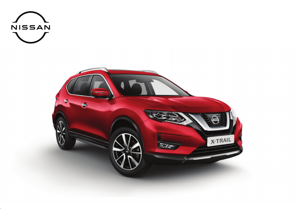
Getting The Most From Your
NISSAN X-TRAIL
OWNER’S MANUAL
Page 2

WELCOME TO YOUR NEW NISSAN X-TRAIL
CONTENTS
Illustrated table of contents 0
Safety — seats, seat belts and supplemental restraint system 1
Instruments and controls 2
Pre-driving checks and adjustments 3
Display screen, heater and air conditioner, and audio system 4
Starting and driving 5
In case of emergency 6
Appearance and care 7
Maintenance and do-it-yourself 8
Technical information 9
Index 10
Page 3
(3,1)
Foreword
This manual was prepared to help you understand the operation and maintenance of your vehicle so that you may enjoy many kilometers (miles) of
driving pleasure. Please read through this manual before operating your vehicle.
A separate Warranty Information & Maintenance Booklet explains details about the warranties covering your vehicle.
Your NISSAN dealer knows your vehicle best. When you require any service or have any questions, we will be glad to assist you with the extensive
resources available for you.
IMPORTANT SAFETY INFORMATION
Reminders for safety!
Follow these important driving rules to help
ensure a safe and complete trip for you and
your passengers!
. NEVER drive under the influence of alco-
hol or drugs.
. ALWAYS observe posted speed limits and
never drive too fast for conditions.
. ALWAYS use your seat belts and appro-
priate child restraint systems. Preteen
children should be seated in the rear seat.
. ALWAYS provide information about the
proper use of vehicle safety features to
all occupants of the vehicle.
. ALWAYS review this Owner’s Manual for
important safety information.
When reading the manual
This manual includes information for all options
available on this model. Therefore, you may find
some information that does not apply to your
vehicle.
Throughout this manual, some illustrations
may only show the layout for Left-Hand Drive
(LHD) models. For Right-Hand Drive (RHD)
models, the illustrated shape and location of
some components may differ.
All information, specifications and illustrations
in this manual are those in effect at the time of
printing. NISSAN reserves the right to change
specifications or designs without notice and
without obligation.
MODIFICATION OF YOUR VEHICLE
This vehicle should not be modified. Modification could affect its performance, safety or
durability, and may even violate governmental
regulations. In addition, damage or performance problems resulting from modifications
may not be covered under NISSAN warranties.
Read first — then drive safely
Before driving your vehicle, read this Owner’s
Manual carefully. This will ensure familiarity
with controls and maintenance requirements,
assisting you in the safe operation of your
vehicle.
Throughout this manual we have used the
symbol
This is used to indicate the presence of a
hazard that could cause death or serious
personal injury. To avoid or reduce the risk,
the procedures must be followed precisely.
The symbol
TION is also used throughout this manual to
indicate the presence of a hazard that could
cause minor or moderate personal injury or
damages to your vehicle. To avoid or reduce
the risk, the procedures must be followed
carefully.
followed by the word WARNING.
followed by the word CAU-
SIC0697
If you see this symbol, it means “Do not do this”
or “Do not let this happen”.
If you see a symbol similar to these in an
illustration, it means the arrow points to the
front of the vehicle.
Arrows in an illustration that are similar to
these indicate movement or action.
Arrows in an illustration that are similar to
these call attention to an item in the illustration.
Page 4
(4,1)
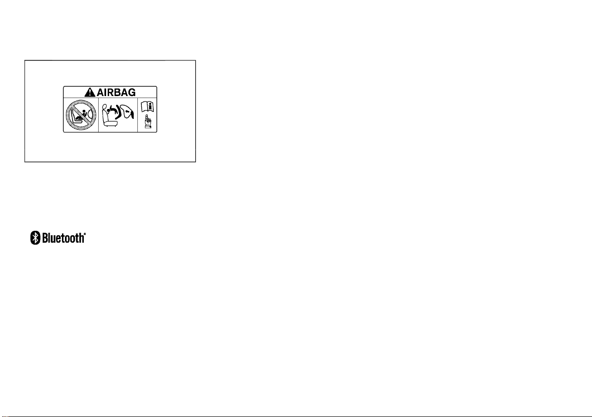
Air bag warning labels (if equipped):
JVR0243X
“NEVER use a rearward facing child restraint on
a seat protected by an ACTIVE AIRBAG in front
of it, DEATH or SERIOUS INJURY to the CHILD
can occur.”
Be sure to read “Air bag warning labels” (P.1-35).
Trademarks:
Bluetooth® is a trademark
owned by Bluetooth SIG,
Inc. and licensed to Visteon
Corporation and Robert
Bosch GmbH.
ON-PAVEMENT AND OFF-ROAD DRIVING (4WD/AWD model)
This vehicle will handle and maneuver differently from an ordinary passenger car, because
it has a higher center of gravity. As with other
vehicles with features of this type, failure to
operate this vehicle correctly may result in loss
of control or an accident.
Be sure to read the “On-pavement and off-road
driving precautions” (P.5-12) of this manual.
© 2020 NISSAN MOTOR CO., LTD.
Page 5

(5,1)
0 Illustrated table of contents
Seats, seat belts and Supplemental Restraint
System (SRS) ......................................................................................................... 0-2
Exterior front ........................................................................................................ 0-3
Exterior rear .......................................................................................................... 0-4
Passenger compartment ........................................................................... 0-5
Cockpit ...................................................................................................................... 0-6
Left-Hand Drive (LHD) model ........................................................... 0-6
Right-Hand Drive (RHD) model ....................................................... 0-8
Instrument panel .......................................................................................... 0-10
Left-Hand Drive (LHD) model ..................................................... 0-10
Right-Hand Drive (RHD) model ................................................. 0-11
Meters and gauges ..................................................................................... 0-12
Engine compartment ................................................................................ 0-13
QR25DE engine model ................................................................... 0-13
MR20DD engine model .................................................................. 0-14
R9M engine model ........................................................................... 0-15
M9R engine model ............................................................................. 0-16
HR13DDT engine model ................................................................ 0-17
Page 6
(6,1)
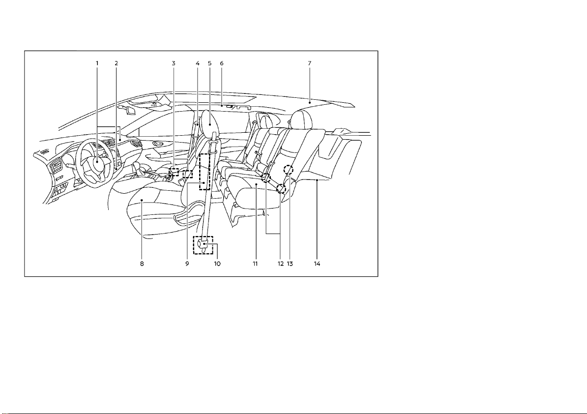
SEATS, SEAT BELTS AND SUPPLEMENTAL
RESTRAINT SYSTEM (SRS)
1. Supplemental front-impact air bags
(P.1-32)
2. Front passenger air bag status light*
— Models with Advanced Air Bag System
(P.1-40)
— Models without Advanced Air Bag Sys-
tem (P.1-43)
3. Occupant classification sensors (weight
sensors) (models with Advanced Air Bag
System)* (P.1-37)
9. Supplemental side-impact air bags*
(P.1-32)
10. Pre-tensioner seat belt system (P.1-48)
11. Second row seats (P.1-5)
— Child restraints (P.1-15)
12. ISOFIX child restraint system (for second
row seats) (P.1-20)
13. Child restraint anchor point (for top tether
strap child restraint) (P.1-21)
14. Third row seats* (P.1-7)
*: if equipped
WAA0049X
4. Seat belts (P.1-10)
5. Head restraints (P.1-8)
6. Supplemental curtain side-impact air
bags* (except for Korea) (P.1-32)
Supplemental curtain side-impact and
rollover air bags (for Korea) (P.1-32)
7. Child restraint anchor point (for top tether
strap child restraint)* (P.1-21)
8. Front seats (P.1-2)
0-2 Illustrated table of contents
Page 7
(7,1)
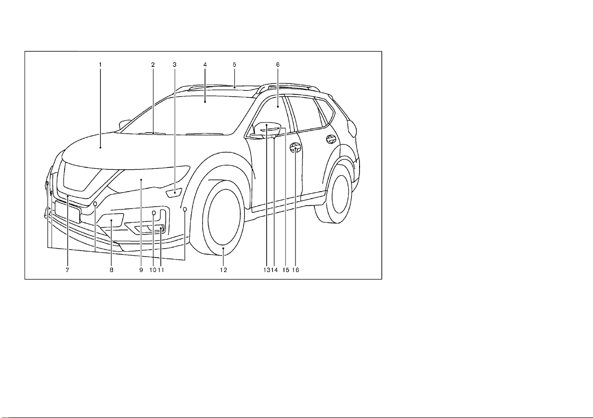
EXTERIOR FRONT
1. Engine hood (P.3-27)
2. Windshield wiper and washer
— Switch operation (P.2-57)
— Window washer fluid (P.8-25)
3. Headlight cleaner* (P.2-54)
4. Front camera* (P.2-41, P.5-40, P.5-44,
P.5-83)
5. Sunroof* (P.2-63)
6. Power windows (P.2-61)
12. Tires
—Tire Pressure Monitoring System
(TPMS)* (P.2-14, P.5-9)
— Tires and wheels (P.8-42, P.9-10)
— Flat tire (P.6-2)
— Tire placard (P.9-13)
13. Outside mirrors (P.3-38)
14. Side view camera* (P.4-11)
15. Side turn signal light (P.2-54)
16. Doors
— Keys (P.3-3)
— Door locks (P.3-5)
— Intelligent Key system* (P.3-11)
— Remote keyless entry system* (P.3-8)
— Security system (P.3-22)
*: if equipped
JVC1026X
7. Front view camera* (P.4-11)
8. Recovery hook (P.6-13)
9. Headlights and turn signal lights (P.2-43)
— Adaptive Front lighting System (AFS)*
(P.2-54)
10. Parking sensor (sonar) system* (P.5-95)
— Intelligent Park Assist* (P.4-19)
—Intelligent Around View Monitor/
Around View Monitor* (P.4-11)
11. Fog lights* (P.2-55)
Illustrated table of contents 0-3
Page 8
(8,1)
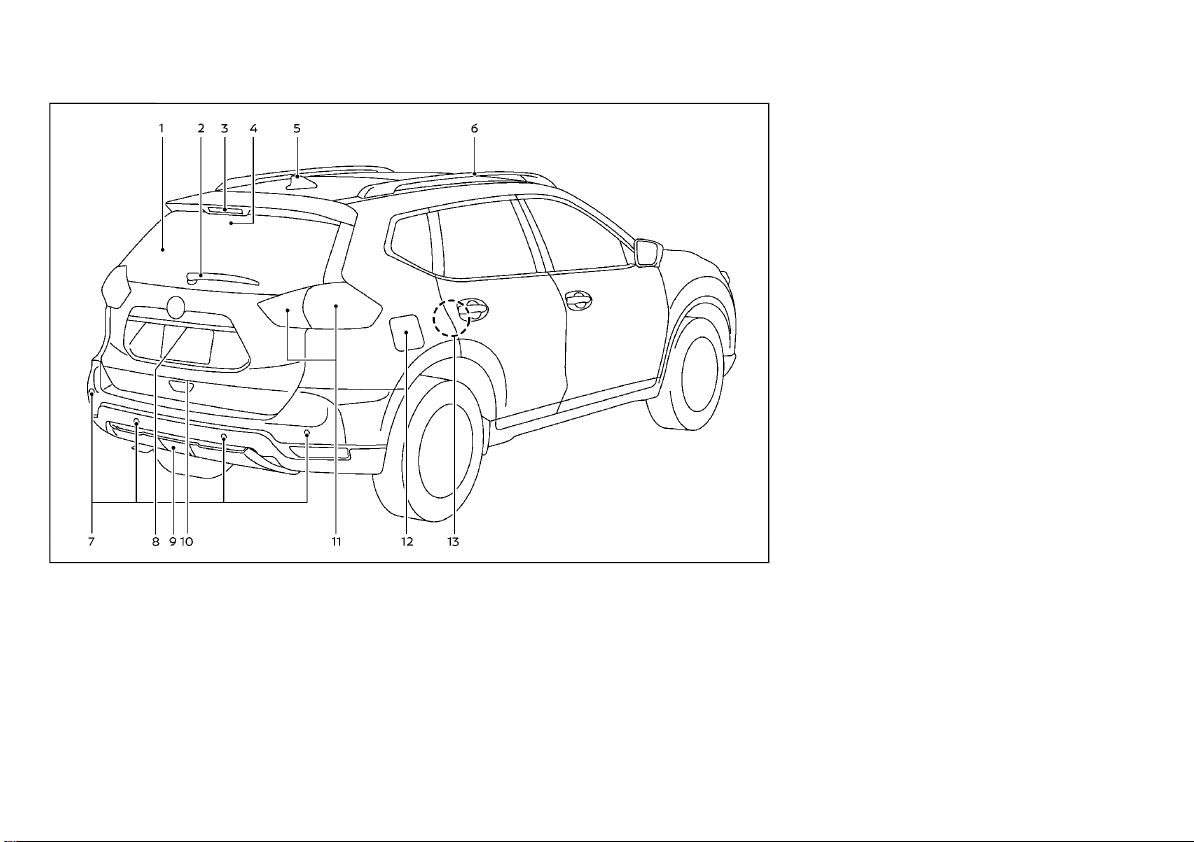
EXTERIOR REAR
1. Rear window defogger (P.2-60)
2. Rear window wiper and washer
— Switch operation (P.2-59)
— Window washer fluid (P.8-25)
3. High-mounted stop light (P.8-35)
4. Intelligent Rear View Mirror camera*
(P.3-35)
5. Antenna (P.4-74)
6. Roof rack* (P.2-72)
11. Rear combination light (P.8-33)
12. Filler lid
— Fuel-filler lid (P.3-31)
— AdBlue® filler lid* (P.3-33)
13. Child safety rear door locks (P.3-8)
*: if equipped
WAA0059X
7. Parking sensor (sonar) system* (P.5-95)
— Intelligent Park Assist* (P.4-19)
—Intelligent Around View Monitor/
Around View Monitor* (P.4-11)
8. Rear view camera* (P.4-7)
9. Rear fog light* (P.2-56)
10. Back door (P.3-28)
— Intelligent Key system* (P.3-11)
— Remote keyless entry system* (P.3-8)
0-4 Illustrated table of contents
Page 9
(9,1)
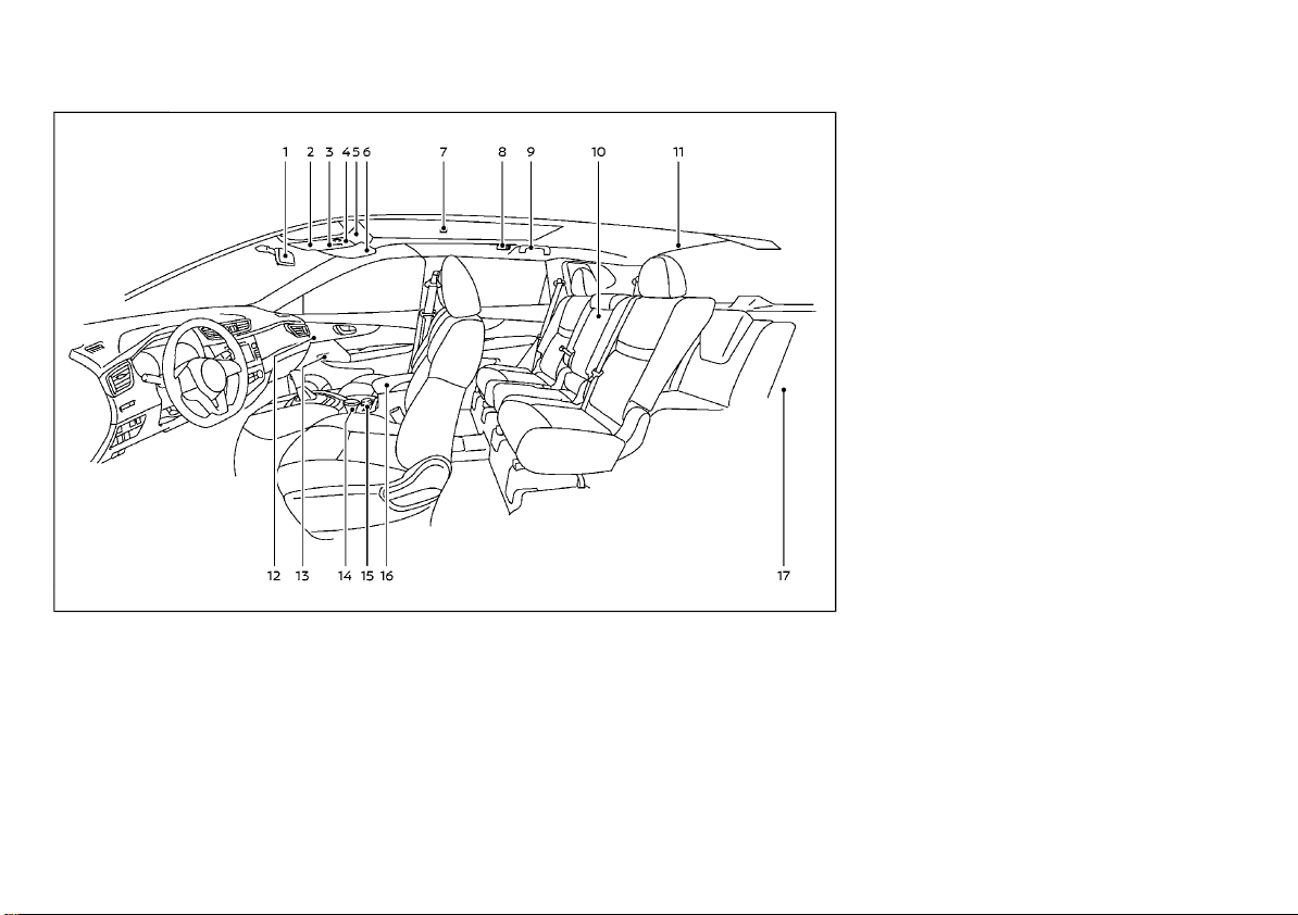
PASSENGER COMPARTMENT
1. Inside rearview mirror (P.3-34)
2. Sunglasses holder (P.2-66)
3. Sunroof switch* (P.2-63)
4. Front map lights (P.2-74)
— Microphone* (P.4-75, P.4-81, P.4-87,
P.4-91, P.4-93 or NissanConnect***)
5. Cancel switch for ultrasonic and tilt sensors* (P.3-23)
6. Sun visors (P.2-73, P.3-39)
7. Room light* (P.2-75)
— Outside rearview mirror remote control
switch (Driver’s side) (P.3-38)
14. Front cup holders (P.2-67)/Ashtray*
(P.2-65)
15. Heated seat switch* (P.1-5, 1-7)
16. Console box (P.2-66)
— USB charging connector* (P.2-65)
17. Luggage room
— Storages (P.2-66)
— Luggage hooks (P.2-69)
— Tonneau cover* (P.2-72)
— Power outlet (P.2-64)
— Spare tire (P.6-2)
— Luggage room light* (P.2-75)
*: if equipped
***: See the separate NissanConnect Owner’s
Manual (if equipped).
WAA0052X
8. Rear personal lights* (P.2-75)
9. Coat hook (Driver’s side)* (P.2-71)
10. Rear armrest (Second row seats) (P.1-8)
— Rear cup holders (P.2-67)
11. Luggage room light* (P.2-75)
12. Automatic drive positioner switch*
(P.3-44)
13. Door armrest
— Power window switch (P.2-61)
— Power door lock switch* (P.3-7)
Illustrated table of contents 0-5
Page 10
(10,1)
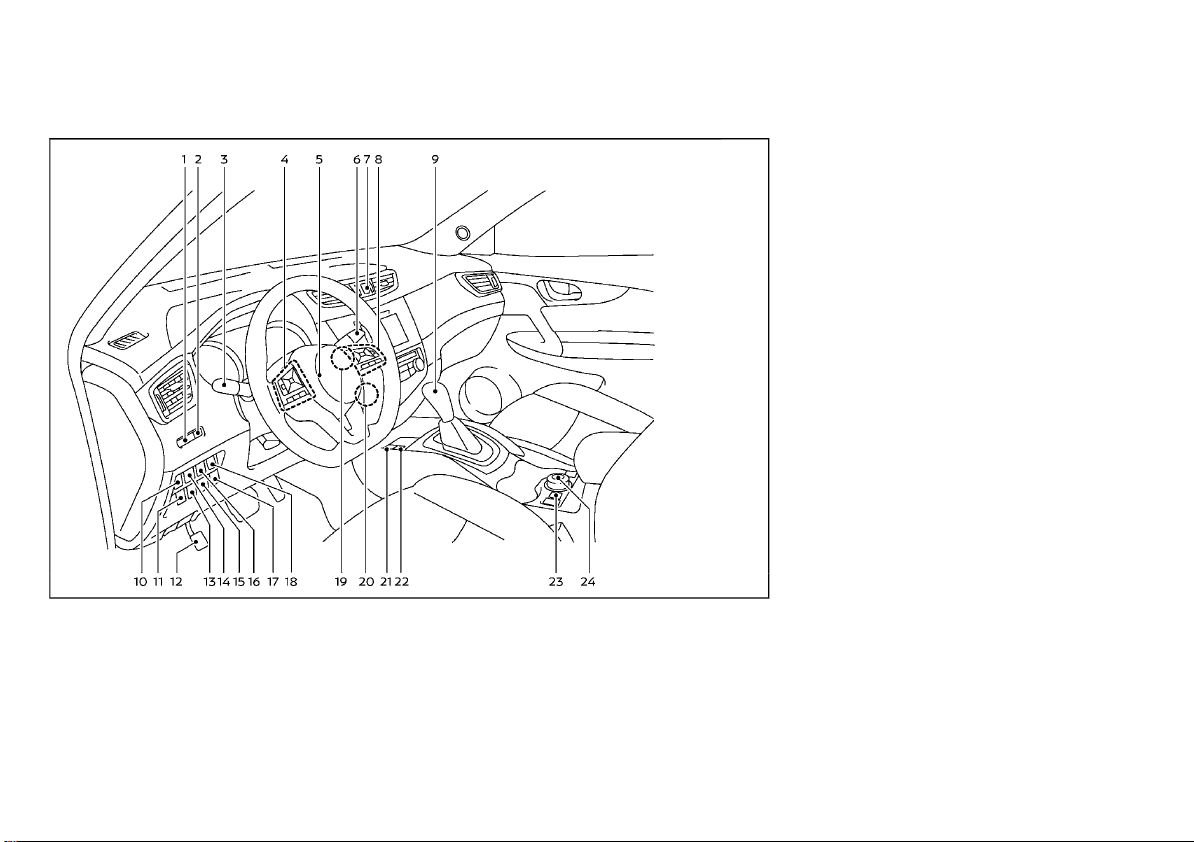
COCKPIT
LEFT-HAND DRIVE (LHD) MODEL
1. Instrument brightness control switch
(P.2-11)
2. TRIP RESET switch (P.2-9)
3. Headlight and turn signal switch (P.2-43)/
Fog light switch* (P.2-55)
4. Steering-wheel-mounted controls (left
side)
— Audio control* (P.4-72, Navigation System** or NissanConnect***)
0-6 Illustrated table of contents
WAA0060X
— Vehicle information display control
(P.2-21)
— Bluetooth® Hands-Free Phone System
(without navigation)* (P.4-75, P.4-87,
P.4-81 or NissanConnect***)
— Bluetooth® Hands-Free Phone System
(with navigation)* (P.4-91 or NissanConnect***)
— Voice recognition system switch* (P.493 or NissanConnect***)
5. Steering wheel (P.3-34)
— Horn (P.2-60)
6. Wiper and washer switch (P.2-57)
7. Hazard indicator flasher switch (P.6-2)
8. Steering-wheel-mounted controls (right
side)
— Cruise control switches* (P.5-62)
— Intelligent Cruise Control (ICC) system
switches* (P.5-64)
— Speed limiter switches* (P.5-60)
— Bluetooth® Hands-Free Phone System
(without navigation)* (P.4-75, P.4-81,
P.4-87 or NissanConnect***)
— Bluetooth® Hands-Free Phone System
(with navigation)* (P.4-91 or NissanConnect***)
— Voice recognition system switch* (P.493 or NissanConnect***)
9. Shift lever
—Continuously Variable Transmission
(CVT) (P.5-19)
— Dual Clutch Transmission (DCT) (P.5-19)
— Manual Transmission (MT) (P.5-23)
10. Vehicle Dynamic Control (VDC) OFF switch
or Electronic Stability Program (ESP) OFF
switch (P.5-36)
11. Heated steering wheel switch* (P.2-61) or
Headlight aiming control switch* (P.2-46)
12. Parking brake (Pedal type)* (P.3-40)
13. Headlight cleaner switch* (P.2-54) or Intelligent 4x4 LOCK switch (for Korea)*
(P.5-33)
14. Lane Departure Warning (LDW) switch*
(P.5-40) or Intelligent Lane Intervention
switch* (P.5-44)
Page 11

(11,1)
15. Stop/Start OFF switch* (P.5-27) or SPORT
mode switch* (P.5-91)
16. Power back door switch* (P.3-28)
17. ECO switch* (P.5-91)
18. Power back door main switch* (P.3-28) or
Fuel-filler lid opener switch* (P.3-31)
19. Push-button ignition switch (model with
Intelligent Key system)* (P.5-14)
20. Ignition switch (model without Intelligent
Key system)* (P.5-13)
21. Parking brake (Switch type)* (P.3-40)
22. Automatic brake hold switch* (P.3-42)
23. Hill descent control switch* (P.5-39)
24. Intelligent 4x4 mode switch* (P.5-28)
*: if equipped
**: See the separate Navigation System
Owner’s Manual (if equipped).
***: See the separate NissanConnect Owner’s
Manual (if equipped).
Illustrated table of contents 0-7
Page 12
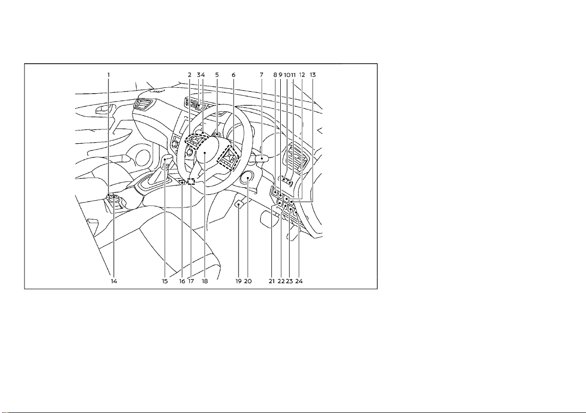
(12,1)
RIGHT-HAND DRIVE (RHD) MODEL
1. Hill descent control switch* (P.5-39)
2. Steering-wheel-mounted controls (left
side)
— Audio control* (P.4-72, Navigation System** or NissanConnect***)
— Vehicle information display control
(P.2-21)
— Bluetooth® Hands-Free Phone System
(without navigation)* (P.4-75, P.4-87 or
NissanConnect***)
WAA0058X
— Bluetooth® Hands-Free Phone System
(with navigation)* (P.4-91 or NissanConnect***)
— Voice recognition system switch* (P.493 or NissanConnect***)
3. Hazard indicator flasher switch (P.6-2)
4. Headlight and turn signal switch (P.2-43)/
Fog light switch* (P.2-55) or Wiper and
washer switch (P.2-57)
5. Push-button ignition switch (model with
Intelligent Key system)* (P.5-14)
6. Steering-wheel-mounted controls (right
side)
— Cruise control switches* (P.5-62)
— Intelligent Cruise Control (ICC) system
switches* (P.5-64)
— Speed limiter switches* (P.5-60)
— Bluetooth® Hands-Free Phone System
(without navigation)* (P.4-75, P.4-87 or
NissanConnect***)
— Bluetooth® Hands-Free Phone System
(with navigation)* (P.4-91 or NissanConnect***)
— Voice recognition system switch* (P.493 or NissanConnect***)
7. Wiper and washer switch (P.2-57) or Headlight and turn signal switch (P.2-43)/Fog
light switch* (P.2-55)
8. Power back door main switch* (P.3-28)
9. Power back door switch* (P.3-28)
10. Instrument brightness control switch
(P.2-11)
11. TRIP RESET switch (P.2-9)
12. Lane Departure Warning (LDW) switch*
(P.5-40) or Intelligent Lane Intervention
switch* (P.5-44)
13. Vehicle Dynamic Control (VDC) OFF switch
or Electronic Stability Program (ESP) OFF
switch (P.5-36)
14. Intelligent 4x4 mode switch* (P.5-28)
15. Shift lever
—Continuously Variable Transmission
(CVT) (P.5-19)
— Dual Clutch Transmission (DCT) (P.5-19)
— Manual Transmission (MT) (P.5-23)
0-8 Illustrated table of contents
Page 13

(13,1)
16. Automatic brake hold switch* (P.3-42)
17. Parking brake (Switch type)* (P.3-40)
18. Steering wheel (P.3-34)
— Horn (P.2-60)
19. Parking brake (Pedal type)* (P.3-40)
20. Ignition switch (model without Intelligent
Key system)* (P.5-13)
21. ECO switch* (P.5-91) or Stop/Start or Idling
Stop OFF switch* (P.5-27)
22. Stop/Start or Idling Stop OFF switch*
(P.5-27)
23. ECO switch* (P.5-91)
24. Heated steering wheel switch* (P.2-61) or
Headlight aiming control switch* (P.2-46)
*: if equipped
**: See the separate Navigation System
Owner’s Manual (if equipped).
***: See the separate NissanConnect Owner’s
Manual (if equipped).
Illustrated table of contents 0-9
Page 14
(14,1)
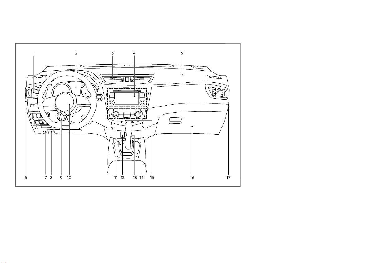
INSTRUMENT PANEL
LEFT-HAND DRIVE (LHD) MODEL
1. Side ventilator (P.4-28)
2. Meters and gauges (P.2-9)/Clock (P.2-40)
3. Center ventilator (P.4-28)
4. Audio system* (P.4-39) or Navigation System** or NissanConnect***
— Center multi-function control panel*
(P.4-4)
— Rear view monitor* (P.4-7)
—Intelligent Around View Monitor/
5. Passenger’s front-impact air bag (P.1-32)
6. Fuse box cover (P.8-30)
7. Fuel-filler lid release handle* (P.3-31) or
Hood lock release handle* (P.3-27)
8. Hood lock release handle* (P.3-27)
9. Steering wheel lock lever (P.3-34)
10. Driver’s front-impact air bag (P.1-32)/Horn
(P.2-60)
11. Heater/air conditioner control (P.4-29)
12. Auxiliary input jack* (P.4-72) and USB
connection port* (P.4-72 or NissanConnect***)
13. Power outlet* (P.2-64) or Cigarette lighter*
(P.2-66)
14. Defogger switch (P.2-60)
15. Front passenger air bag status light*
(P.1-40, P.1-43)
16. Glove box (P.2-66)
17. Fuse box cover* (P.8-30)
*: if equipped
**: See the separate Navigation System
Owner’s Manual (if equipped).
***: See the separate NissanConnect Owner’s
Manual (if equipped).
WAA0061X
Around View Monitor* (P.4-11)
— Bluetooth® Hands-Free Phone System
(without navigation)* (P.4-75, P.4-81,
P.4-87 or NissanConnect***)
— Bluetooth® Hands-Free Phone System
(with navigation)* (P.4-91 or NissanConnect***)
— Voice Recognition System* (P.4-93 or
NissanConnect***)
0-10 Illustrated table of contents
Page 15
(15,1)
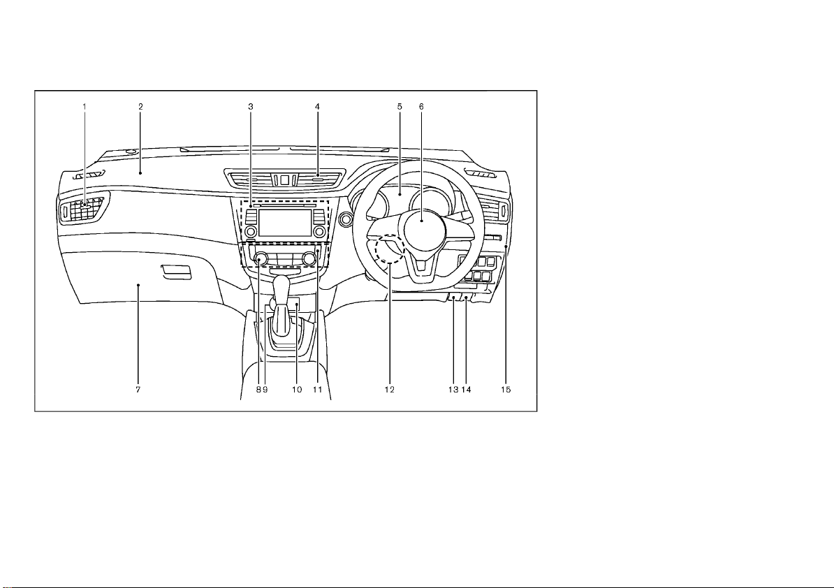
RIGHT-HAND DRIVE (RHD) MODEL
1. Side ventilator (P.4-28)
2. Passenger’s front-impact air bag (P.1-32)
3. Audio system* (P.4-39) or Navigation System** or NissanConnect***
— Center multi-function control panel*
(P.4-4)
— Rear view monitor* (P.4-7)
—Intelligent Around View Monitor/
Around View Monitor* (P.4-11)
5. Meters and gauges (P.2-9)/Clock (P.2-40)
6. Driver’s front-impact air bag (P.1-32)/Horn
(P.2-60)
7. Glove box (P.2-66)
— Fuse box (P.8-30)
8. Heater/air conditioner control (P.4-29)
9. Power outlet* (P.2-64) or Cigarette lighter*
(P.2-66) or Auxiliary input jack* (P.4-72)
and USB connection port* (P.4-72 or
NissanConnect***)
10. Auxiliary input jack* (P.4-72) and USB
connection port* (P.4-72 or NissanConnect***) or Power outlet* (P.2-64) or Cigarette lighter* (P.2-66)
11. Defogger switch (P.2-60)
12. Steering wheel lock lever (P.3-34)
13. Hood release handle (P.3-27)
14. Fuel-filler lid release handle (P.3-31)
15. Fuse box cover* (P.8-30)
*: if equipped
**: See the separate Navigation System
Owner’s Manual (if equipped).
***: See the separate NissanConnect Owner’s
Manual (if equipped).
JVC1028X
— Bluetooth® Hands-Free Phone System
(without navigation)* (P.4-75, P.4-87 or
NissanConnect***)
— Bluetooth® Hands-Free Phone System
(with navigation)* (P.4-91 or NissanConnect***)
— Voice Recognition System* (P.4-93 or
NissanConnect***)
4. Center ventilator (P.4-28)
Illustrated table of contents 0-11
Page 16
(16,1)
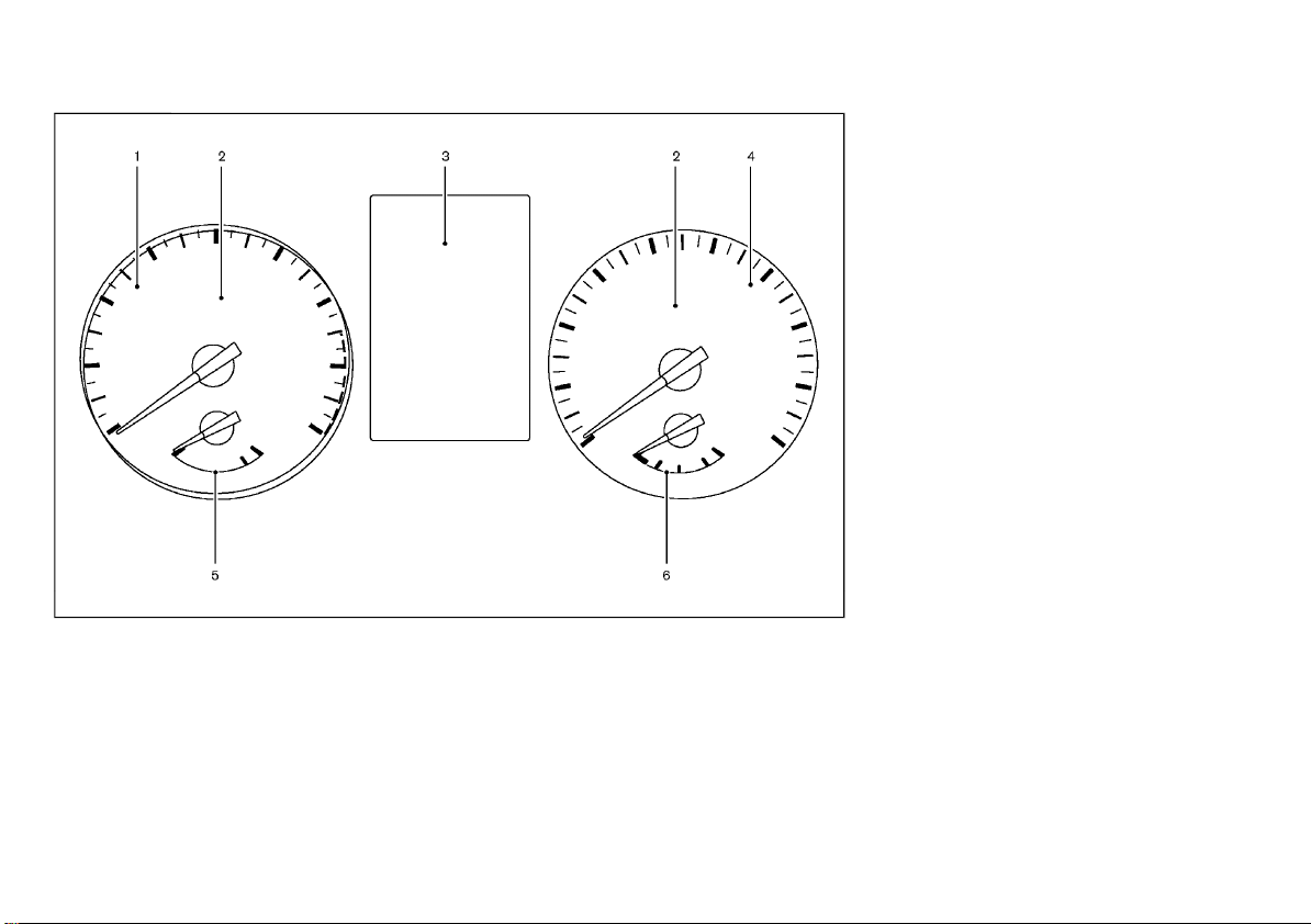
METERS AND GAUGES
1. Tachometer (P.2-10)
2. Warning/indicator lights (P.2-12)
3. Vehicle information display (P.2-21)
— Odometer/twin trip odometer (P. 2-9)
4. Speedometer (P.2-9)
5. Engine coolant temperature gauge
(P.2-10)
6. Fuel gauge (P.2-11)
JVC0581X
0-12 Illustrated table of contents
Page 17
(17,1)
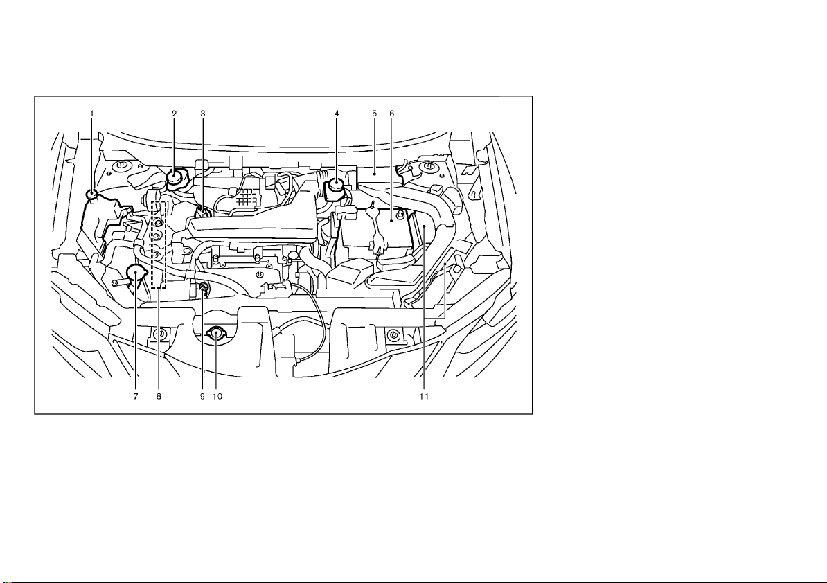
ENGINE COMPARTMENT
QR25DE ENGINE MODEL
1. Engine coolant reservoir (P.8-12)
2. Brake fluid reservoir (P.8-21) — RHD model
3. Engine oil filler cap (P.8-13)
4. Brake fluid reservoir (P.8-21) — LHD model
5. Air cleaner (P.8-23)
6. Battery (P.8-26)
7. Window washer fluid reservoir (P.8-25)
JVC0580X
8. Engine drive belts (P.8-18)
9. Engine oil dipstick (P.8-13)
10. Radiator cap (P.8-11)
— Vehicle overheat (P.6-11)
11. Fuse/fusible link box (P.8-30)
Illustrated table of contents 0-13
Page 18
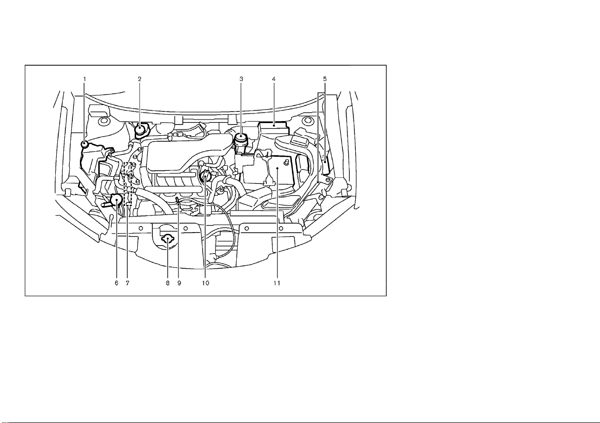
(18,1)
MR20DD ENGINE MODEL
1. Engine coolant reservoir (P.8-12)
2. Brake and clutch* fluid reservoir (P.8-21) —
RHD model
3. Brake and clutch* fluid reservoir (P.8-21) —
LHD model
4. Air cleaner (P.8-23)
5. Fuse/fusible link box (P.8-30)
6. Window washer fluid reservoir (P.8-25)
JVC0592X
7. Engine drive belts (P.8-18)
8. Radiator cap (P.8-11)
— Vehicle overheat (P.6-11)
9. Engine oil dipstick (P.8-13)
10. Engine oil filler cap (P.8-13)
11. Battery (P.8-26)
*: For Manual Transmission (MT) Model
0-14 Illustrated table of contents
Page 19
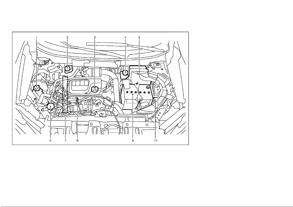
(19,1)
R9M ENGINE MODEL
1. Engine coolant reservoir (P.8-12)
2. Brake and clutch* fluid reservoir (P.8-21) —
RHD model
3. Engine oil filler cap (P.8-13)
4. Brake and clutch* fluid reservoir (P.8-21) —
LHD model
5. Air cleaner (P.8-23)
6. Window washer fluid reservoir (P.8-25)
JVC0640X
7. Engine drive belts (P.8-18)
8. Engine oil dipstick (P.8-13)
9. Battery (P.8-26)
10. Fuse/fusible link box (P.8-30)
*: For Manual Transmission (MT) Model
Illustrated table of contents 0-15
Page 20
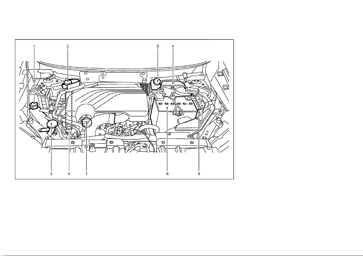
(20,1)
M9R ENGINE MODEL
1. Engine coolant reservoir (P.8-12)
2. Brake and clutch* fluid reservoir (P.8-21,
P.8-22) — RHD model
3. Brake and clutch* fluid reservoir (P.8-21,
P.8-22) — LHD model
4. Air cleaner (P.8-23)
5. Window washer fluid reservoir (P.8-25)
6. Engine drive belts (P.8-18)
JVC0971X
7. Engine oil filler cap/Engine oil dipstick
(P.8-13)
8. Battery (P.8-26)
9. Fuse/Fusible link box (P.8-30)
*: For Manual Transmission (MT) Model
0-16 Illustrated table of contents
Page 21
(21,1)
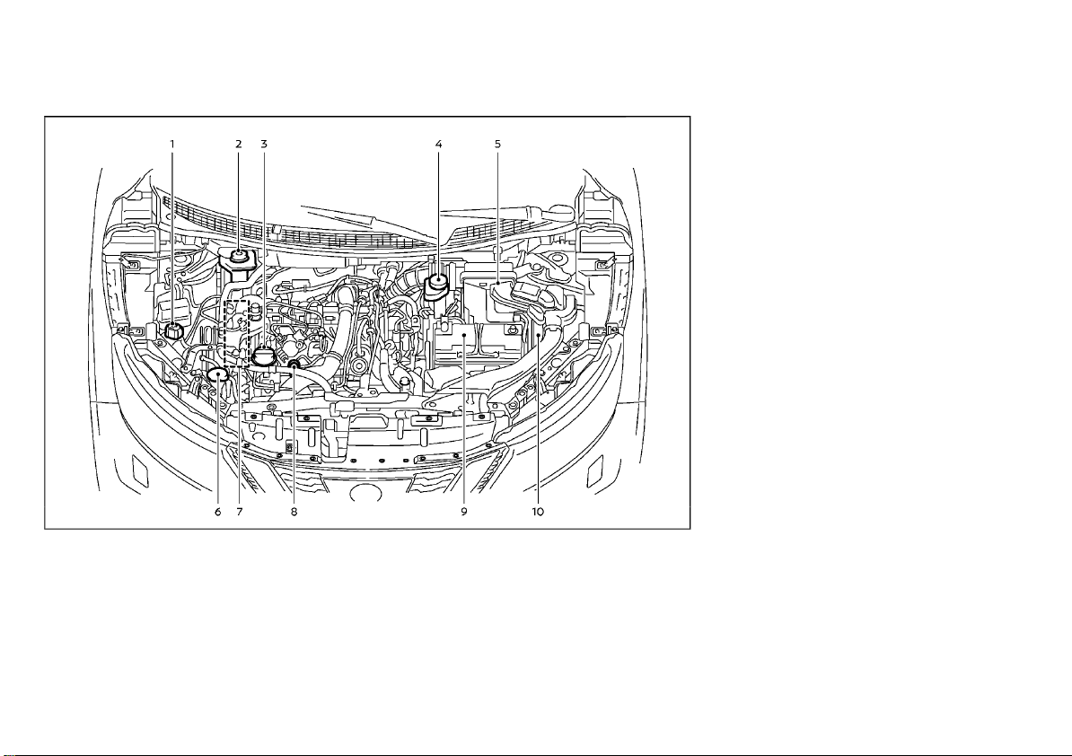
HR13DDT ENGINE MODEL
1. Engine coolant reservoir (P.8-12)
2. Brake and clutch fluid reservoir (P.8-21) —
RHD model
3. Engine oil filler cap (P.8-13)
4. Brake and clutch fluid reservoir (P.8-21) —
LHD model
5. Air cleaner (P.8-23)
6. Window washer fluid reservoir (P.8-25)
WAA0051X
7. Engine drive belts (P.8-18)
8. Engine oil dipstick (P.8-13)
9. Battery (P.8-26)
10. Fuse/fusible link box (P.8-30)
Illustrated table of contents 0-17
Page 22

(22,1)
MEMO
0-18 Illustrated table of contents
Page 23

(23,1)
1 Safety — seats, seat belts and supplemental
restraint system
Seats ........................................................................................................................... 1-2
Front seats ..................................................................................................... 1-2
Second row seats ..................................................................................... 1-5
Third row seats (if equipped) .......................................................... 1-7
Armrest .............................................................................................................. 1-8
Head restraints ................................................................................................... 1-8
Adjustable head restraint ................................................................... 1-8
Non-adjustable head restraint ....................................................... 1-8
Remove ............................................................................................................. 1-9
Install ................................................................................................................... 1-9
Adjust .................................................................................................................. 1-9
Seat belts ............................................................................................................. 1-10
Precautions on seat belt usage ................................................. 1-10
Child safety ................................................................................................. 1-12
Pregnant women ................................................................................... 1-12
Injured persons ........................................................................................ 1-13
Center mark on seat belts ............................................................. 1-13
Three-point type seat belts ........................................................... 1-13
Seat belt maintenance ...................................................................... 1-14
Child restraints ............................................................................................... 1-15
Precautions on child restraint usage .................................. 1-15
Universal child restraints for front seat and rear
seats (for Argentina and Europe) ........................................... 1-16
ISOFIX child restraint system (for second
row seats) .................................................................................................. 1-20
Child restraint anchorage (for second
row seats) .................................................................................................. 1-21
Child restraint installation using ISOFIX ........................... 1-21
Child restraint installation using three-point type
seat belt ...................................................................................................... 1-23
Supplemental Restraint System (SRS) ......................................... 1-32
Precautions on Supplemental Restraint
System (SRS) ........................................................................................... 1-32
Supplemental air bag systems ................................................. 1-37
SRS air bag deployment conditions .................................... 1-45
Pre-tensioner seat belt system ................................................ 1-48
Repair and replacement procedure ..................................... 1-48
Page 24
(24,1)
SEATS
Manual seat adjustment
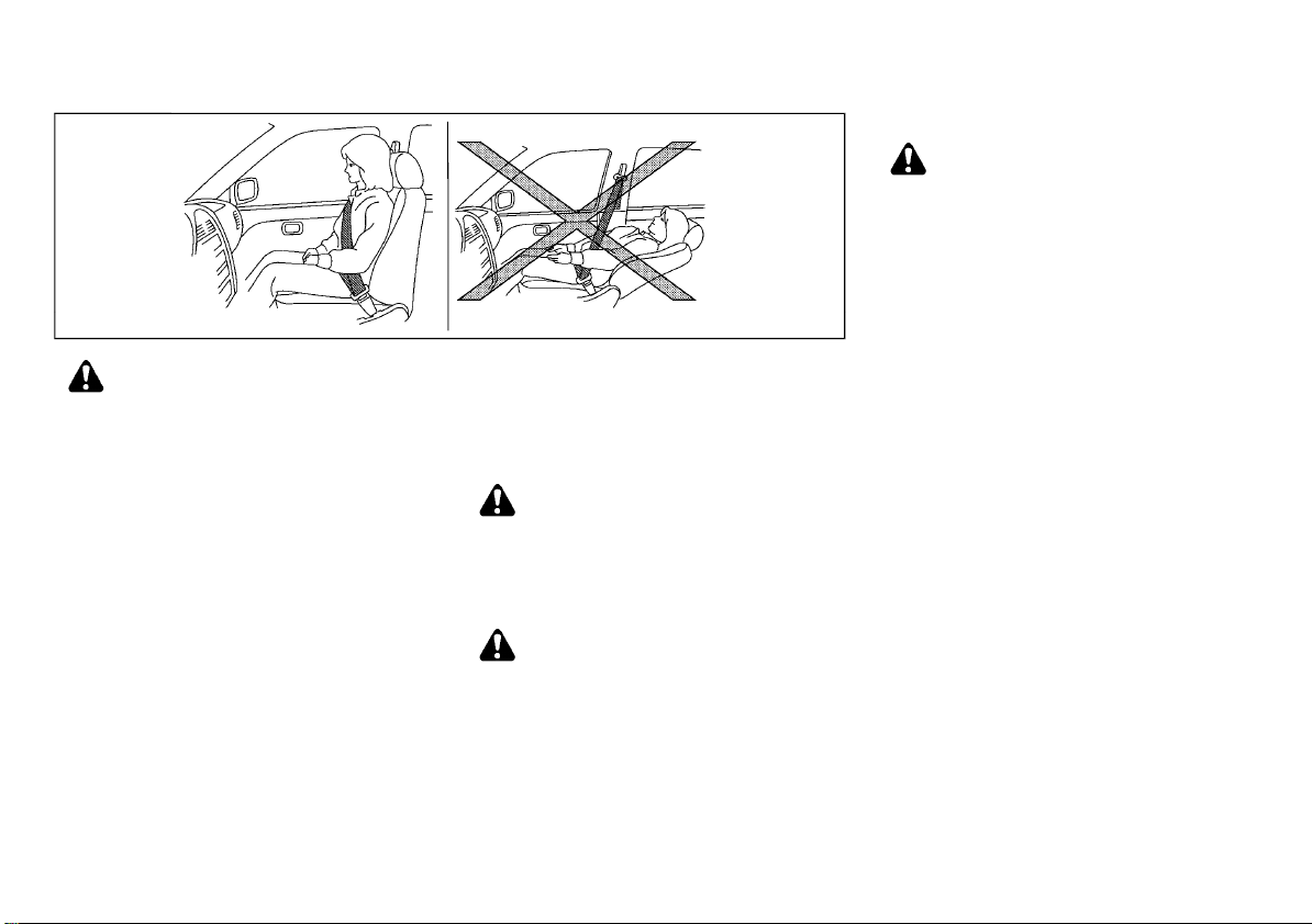
WARNING:
After adjusting a seat, gently shake the seat
to confirm that the seat is locked securely. If
the seat is not locked securely, it may move
suddenly and could cause the loss of control
of the vehicle.
SSS0133A
WARNING:
. Do not drive and/or ride in the vehicle
with the seatback reclined. This can be
dangerous. The shoulder belt will not be
properly against the body. In an accident,
you and your passengers could be
thrown into the shoulder belt and receive
neck or other serious injuries. You and
your passengers could also slide under
the lap belt and receive serious injuries.
. For the most effective protection while
the vehicle is in motion, the seatback
should be upright. Always sit well back
and upright in the seat and adjust the
seat belt properly. (See “Seat belts” (P.1-
10).)
. Do not leave children unattended inside
the vehicle. They could unknowingly activate switches or controls. Unattended
children could become involved in serious accidents.
. To help avoid risk of injury or death
through unintended operation of the
vehicle and/or its systems, do not leave
children, people who require the assis-
1-2 Safety — seats, seat belts and supplemental restraint system
tance of others or pets unattended in
your vehicle. Additionally, the temperature inside a closed vehicle on a warm
day can quickly become high enough to
cause a significant risk of injury or death
to people and pets.
CAUTION:
When adjusting the seat positions, be sure
not to contact any moving parts to avoid
possible injuries and/or damages.
FRONT SEATS
WARNING:
Do not adjust the driver’s seat while driving
so that full attention may be given to vehicle
operation.
Page 25
(25,1)
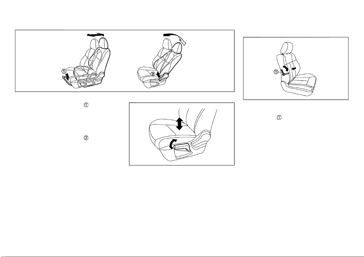
Forward and backward:
1. Pull up the adjusting lever .
2. Slide the seat to the desired position.
3. Release the adjusting lever to lock the seat
in position.
Reclining:
1. Pull up the adjusting lever .
2. Tilt the seatback to the desired position.
3. Release the adjusting lever to lock the
seatback in position.
The reclining feature allows the adjustment of
the seatback for occupants of different sizes to
help obtain the proper seat belt fit. (See “Seat
belts” (P.1-10).)
The seatback may be reclined to allow occupants to rest when the vehicle is parked.
JVR0332X
Seat lifter (if equipped):
JVR0333X
Pull up or push down the adjusting lever to
adjust the seat height until the desired position
is achieved.
Lumbar support (if equipped):
SSS0684
The lumbar support feature provides lower
back support to the driver.
Move the lever
up or down to adjust the seat
lumbar area.
Safety — seats, seat belts and supplemental restraint system 1-3
Page 26
(26,1)
Power seat adjustment
Operating tips:
. The power seat motor has an auto-reset
overload protection circuit. If the motor
stops during the seat adjustment, wait 30
seconds, then reactivate the switch.
. To avoid discharge of the battery, do not
operate the power seats for a long period
of time when the engine is not running.
For automatic drive positioner operation (if
equipped), see “Automatic drive positioner”
(P.3-44).
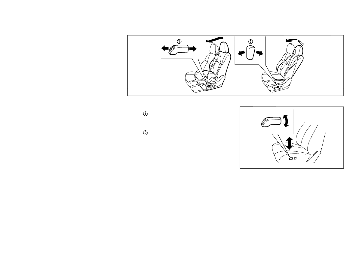
Forward and backward:
Move forward or backward the adjusting
switch
Reclining:
Move forward or backward the adjusting
switch
The reclining feature allows the adjustment of
the seatback for occupants of different sizes to
help obtain the proper seat belt fit. (See “Seat
belts” (P.1-10).)
The seatback may be reclined to allow occupants to rest when the vehicle is parked.
to the desired position.
to the desired position.
JVR0334X
Seat lifter (if equipped):
JVR0119X
Pull up or push down the adjusting switch to
adjust the seat height until the desired position
is achieved.
1-4 Safety — seats, seat belts and supplemental restraint system
Page 27
(27,1)
Lumbar support (if equipped):
SSS1053
The lumbar support feature provides lower
back support to the driver.
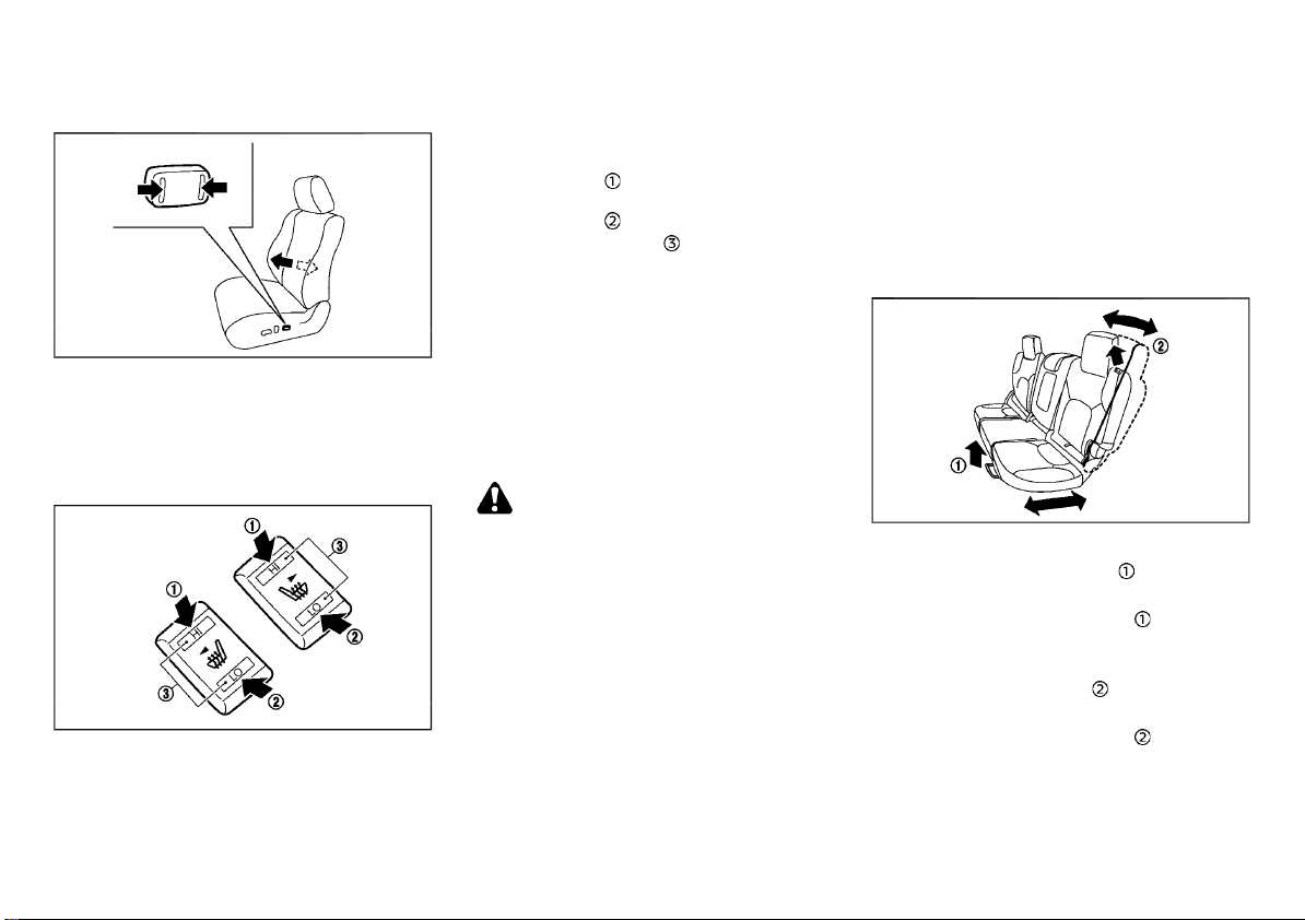
Push each side of the adjusting switch to adjust
the seat lumbar area until the desired position
is achieved.
Heated seats (if equipped)
JVR0322X
The front seats can be warmed by built-in
heaters. The switches located on the center
console can be operated independently of each
other.
1. Start the engine.
2. Select heat range.
.
For high heat, push the HI (High) side of
the switch
.
For low heat, push the LO (Low) side of
the switch
.
The indicator light will illuminate when
.
.
low or high is selected.
3. To turn off the heater, return the switch to
the level position. Make sure the indicator
light turns off.
The heater is controlled by a thermostat,
automatically turning the heater on and off.
The indicator light will remain on as long as
the switch is on.
When the vehicle’s interior is warmed, or
before you leave the vehicle, be sure to turn
off the switch.
CAUTION:
. The battery could run down if the seat
heater is operated while the engine is not
running.
. Do not use the seat heater for extended
periods or when no one is using the seat.
. Do not put anything on the seat which
insulates heat, such as a blanket, cushion,
seat cover, etc. Otherwise, the seat may
become overheated.
. Do not place anything hard or heavy on
the seat or pierce it with a pin or similar
object. This may result in damage to the
seat heater.
. Any liquid spilled on the heated seat
should be removed immediately with a
dry cloth.
. When cleaning the seat, never use gaso-
line, thinner, or any similar materials.
. If any malfunctions are found or the
heated seat does not operate, turn the
switch off and have the system checked
by a NISSAN dealer.
SECOND ROW SEATS
Adjustment
JVR0330X
Forward and backward (if equipped):
1. Pull up the adjusting lever .
2. Slide the seat to the desired position.
3. Release the adjusting lever
seat in position.
Reclining (if equipped):
1. Pull the adjusting lever .
2. Tilt the seatback to the desired position.
3. Release the adjusting lever
seatback in position.
The reclining feature allows the adjustment of
the seatback for occupants of different sizes to
help obtain the proper seat belt fit. (See “Seat
belts” (P.1-10).)
to lock the
to lock the
Safety — seats, seat belts and supplemental restraint system 1-5
Page 28
(28,1)
The seatback may be reclined to allow occupants to rest when the vehicle is parked.
JVR0449X
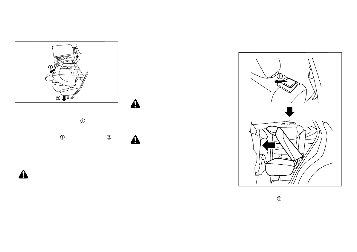
Folding:
1. For vehicles not equipped with third row
seat: Pull up the lever
seatback flat.
For vehicles equipped with third row seat:
Pull up the lever
the lower side of the outboard seats to fold
the seatback flat.
2. To return the seats to a seating position,
push up on the seatback until it latches in
place.
and pull the strap on
and fold the
WARNING:
. Never allow anyone to ride in the luggage
area or on the rear seats when they are in
the fold-down position. Use of these
areas by passengers without proper restraints could result in serious injury in an
accident or sudden stop.
. Do not fold down the second row seats
when occupants are in the second row
seat area or any luggage is on the second
row seats.
. Properly secure all luggage to help pre-
vent it from sliding or shifting. Do not
place luggage higher than the seatbacks.
. When returning the seatbacks to the
upright position, be certain they are
completely secured in the latched position. If they are not completely secured,
passengers may be injured in an accident
or sudden stop.
Walk-in mechanism (Three row model):
The second row seats can tilt and slide for easy
entry/exit to/from the third row seats.
WARNING:
After operating the walk-in mechanism, be
sure to return the seat to the rearmost
position and then tilt up the seatback until
it latches.
CAUTION:
. When operating the walk-in mechanism,
push and hold the seatback and operate
slowly. If the seatback is tilted down
quickly and then allowed to slide, there
is a risk that it could contact your face or
other parts of your body, or pinch your
hand or foot, causing injury.
. When operating the walk-in mechanism,
be sure not to contact any moving parts
to avoid possible injuries and/or damage.
. When operating the walk-in mechanism,
be sure that the second row seats are not
occupied by passengers and/or any objects to avoid possible injuries and/or
damage.
. Do not operate the walk-in mechanism
with objects, drinks, etc. on the seat. This
may cause objects to break or cause the
passenger room to be soiled.
JVR0355X
1. Pull the lever to tilt down the seatback.
2. Slide the seat forward.
3. When returning the seat to its original
position, tilt the seatback up, slide the seat
backward and then secure it in place.
1-6 Safety — seats, seat belts and supplemental restraint system
Page 29
(29,1)
Heated seats (if equipped)
JVR0525X
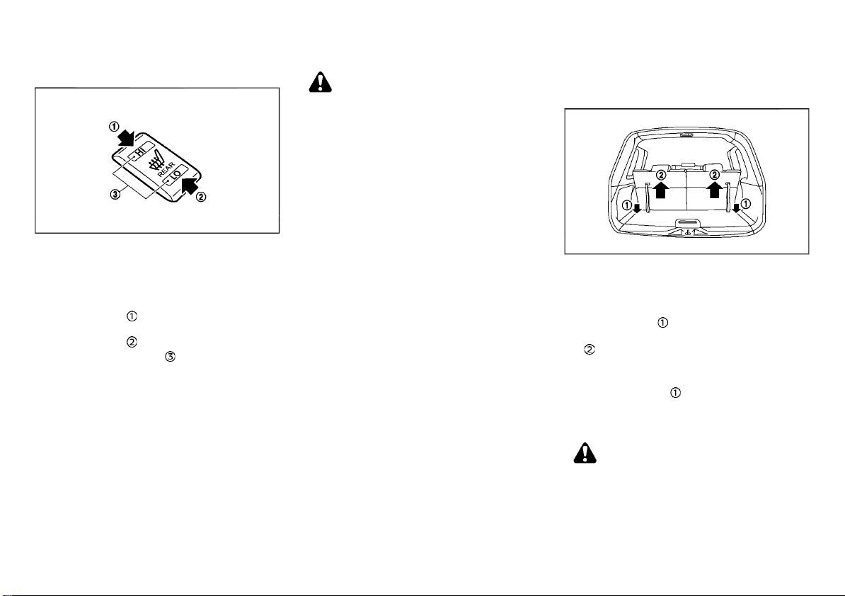
The seats can be warmed by built-in heaters.
The switch is located on the center console.
1. Start the engine.
2. Select heat range.
.
For high heat, push the HI (High) side of
the switch
.
For low heat, push the LO (Low) side of
the switch
.
The indicator light will illuminate when
the heater is on.
3. To turn off the heater, return the switch to
the level position. Make sure the indicator
light turns off.
The heater is controlled by a thermostat,
automatically turning the heater on and off.
The indicator light will remain on as long as
the switch is on.
When the vehicle’s interior is warmed, or
before you leave the vehicle, be sure to turn
off the switch.
.
.
CAUTION:
. The battery could run down if the seat
heater is operated while the engine is not
running.
. Do not use the seat heater for extended
periods or when no one is using the seat.
. Do not put anything on the seat which
insulates heat, such as a blanket, cushion,
seat cover, etc. Otherwise, the seat may
become overheated.
. Do not place anything hard or heavy on
the seat or pierce it with a pin or similar
object. This may result in damage to the
seat heater.
. Any liquid spilled on the heated seat
should be removed immediately with a
dry cloth.
. When cleaning the seat, never use gaso-
line, thinner, or any similar materials.
. If any malfunctions are found or the
heated seat does not operate, turn the
switch off and have the system checked
by a NISSAN dealer.
THIRD ROW SEATS (if equipped)
Folding
JVR0329X
To fold the third row seats flat for maximum
cargo capacity:
1. Make sure the head restraints are all the
way down.
2. Pull the strap
3. Once released, push the seatback forward
.
To return the third row seats to a seating
position:
Use the pull straps
Pull back until the seatback latches into position. Make sure to properly raise each seatback
to an upright and secured position.
WARNING:
When the seat is returned to the normal
seating position, the head restraints must be
returned to the upright position to properly
protect vehicle occupants.
to release the seat.
to raise each seatback.
Safety — seats, seat belts and supplemental restraint system 1-7
Page 30
(30,1)
HEAD RESTRAINTS
ARMREST
Fold down the armrest while pulling the strap
(if equipped) until it is horizontal.
Second row seats
JVR0337X
WARNING:
Head restraints supplement the other vehicle
safety systems. They may provide additional
protection against injury in certain rear end
collisions. Adjustable head restraints must be
adjusted properly, as specified in this section.
Check the adjustment after someone else
uses the seat. Do not attach anything to the
head restraint stalks or remove the head
restraint. Do not use the seat if the head
restraint has been removed. If the head
restraint was removed, reinstall and properly
adjust the head restraint before an occupant
uses the seating position. Failure to follow
these instructions can reduce the effectiveness of the head restraint. This may increase
the risk of serious injury or death in a
collision.
. Your vehicle is equipped with a head
restraint that may be integrated, adjustable
or non-adjustable.
. Adjustable head restraints have multiple
notches along the stalk to lock them in a
desired adjustment position.
. The non-adjustable head restraints have
single locking notch to secure them to the
seat frame.
. Proper Adjustment:
— For the adjustable type, align the head
restraint so the center of your ear is
approximately level with the center of
the head restraint.
— If your ear position is still higher than the
recommended alignment, place the
head restraint at the highest position.
. If the head restraint has been removed,
ensure that it is reinstalled and locked in
place before riding in that designated
seating position.
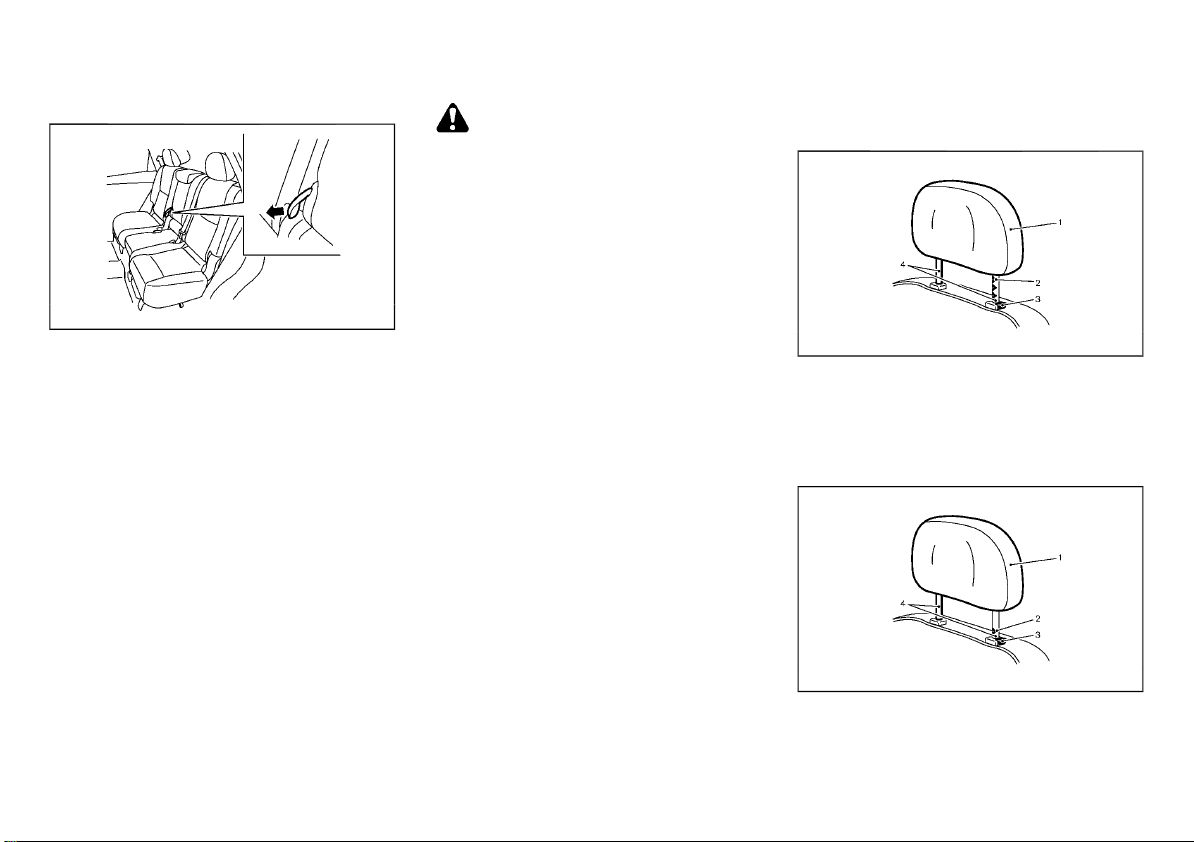
ADJUSTABLE HEAD RESTRAINT
SSS0992
1. Removable head restraint
2. Multiple notches
3. Lock knob
4. Stalks
NON-ADJUSTABLE HEAD RESTRAINT
JVR0203X
1. Removable head restraint
2. Single notch
1-8 Safety — seats, seat belts and supplemental restraint system
Page 31
(31,1)
3. Lock knob
4. Stalks
REMOVE
SSS1037
Use the following procedure to remove the
head restraint.
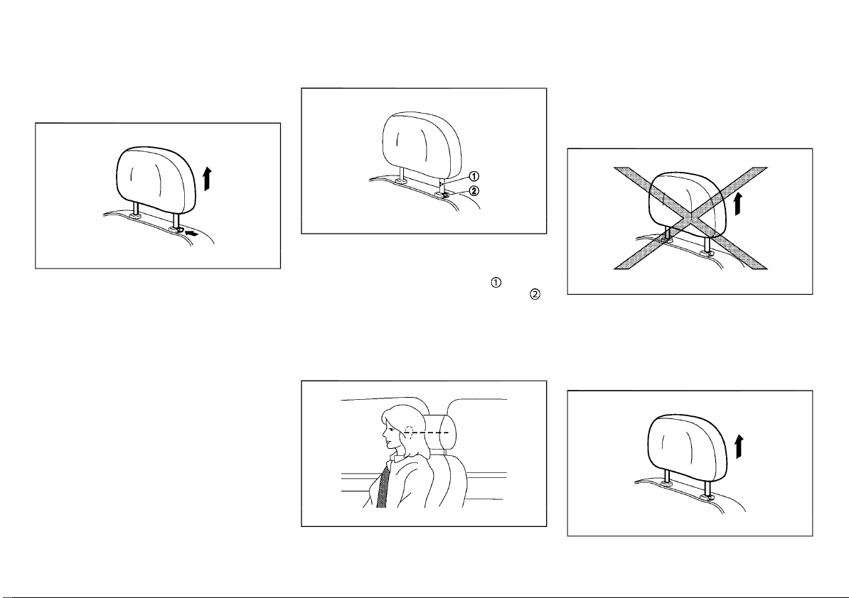
1. Pull the head restraint up to the highest
position.
2. Push and hold the lock knob.
3. Remove the head restraint from the seat.
4. Store the head restraint properly in a
secure place so it is not loose in the vehicle.
5. Reinstall and properly adjust the head
restraint before an occupant uses the
seating position.
INSTALL
SSS1038
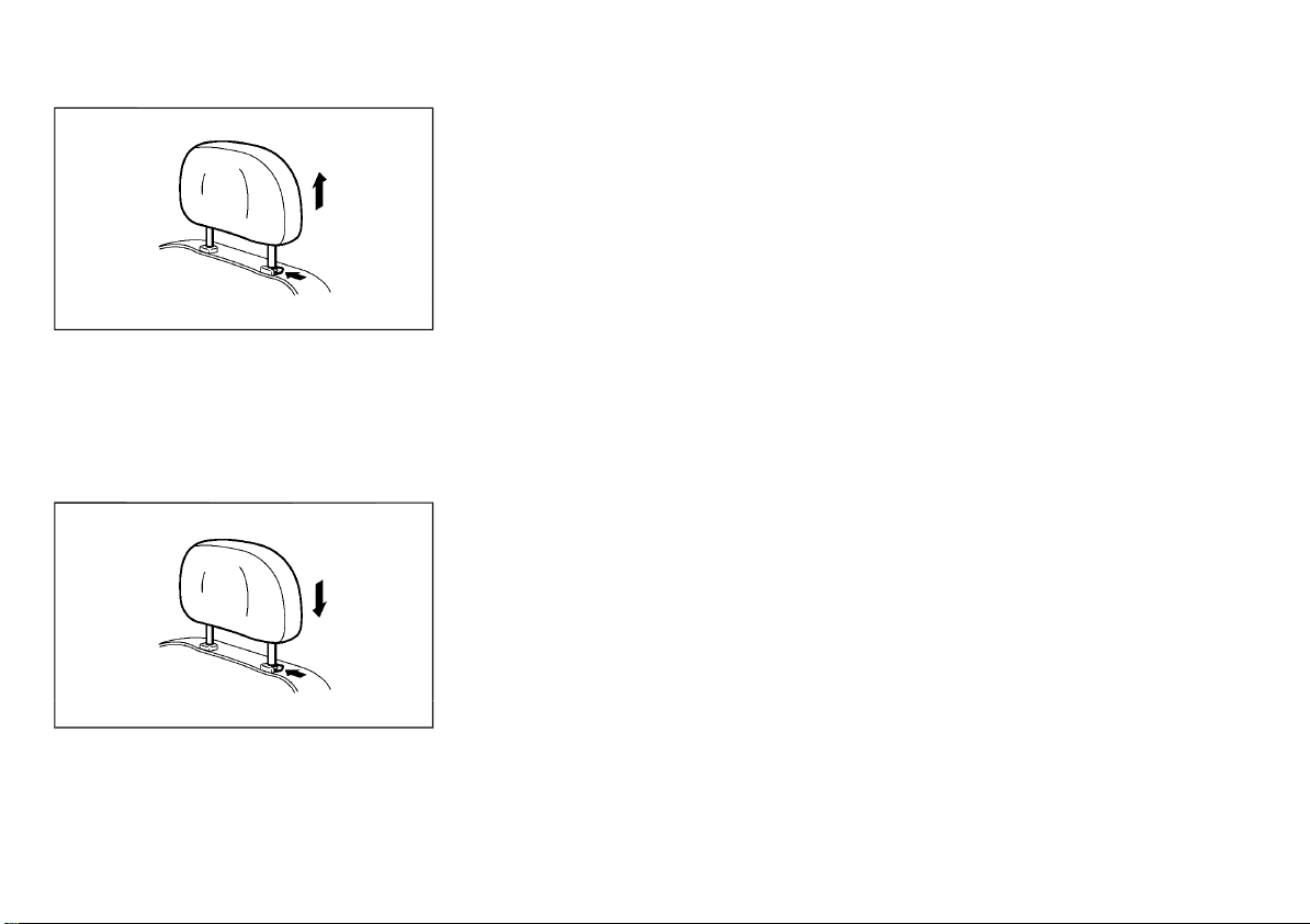
1. Align the head restraint stalks with the
holes in the seat. Make sure that the head
restraint is facing the correct direction. The
stalk with the adjustment notch
must be
installed in the hole with the lock knob
2. Push and hold the lock knob and push the
head restraint down.
3. Properly adjust the head restraint before an
occupant uses the seating position.
ADJUST
For adjustable head restraint
Adjust the head restraint so the center is level
with the center of your ears. If your ear position
is still higher than the recommended alignment, place the head restraint at the highest
position.
.
For non-adjustable head restraint
Make sure the head restraint is positioned from
the stored position or any non-latch position so
the lock knob is engaged in the notch before
riding in that designated seating position.
Raise
JVR0259X
SSS0997
To raise the head restraint, pull it up.
Type A
SSS1035
Safety — seats, seat belts and supplemental restraint system 1-9
Page 32
(32,1)
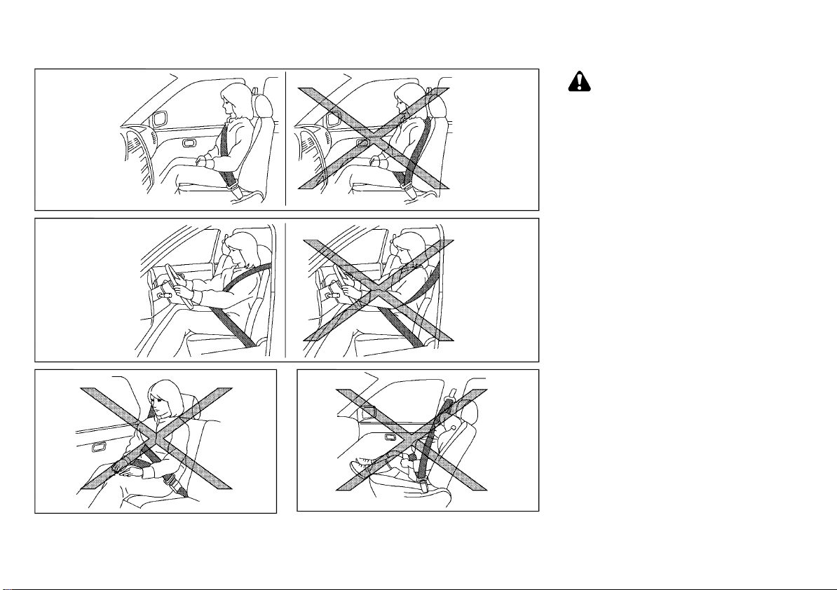
To raise the head restraint, push and hold the
lock knob. Then, pull it up.
Make sure the head restraint is positioned from
the stored position or any non-latch position so
the lock knob is engaged in the notch before
riding in that designated seating position.
Type B
SSS1037
Lower
SEAT BELTS
PRECAUTIONS ON SEAT BELT USAGE
If you are wearing the seat belt properly
adjusted and sitting upright and well back in
the seat, chances of being injured or killed in an
accident and/or the severity of injury may be
greatly reduced. NISSAN strongly encourages
you and all of your passengers to buckle up
every time you drive, even if your seating
position includes the supplemental air bag
systems.
SSS1036
To lower, push and hold the lock knob and
push the head restraint down.
Make sure the head restraint is positioned so
the lock knob is engaged in the notch before
riding in that designated seating position.
1-10 Safety — seats, seat belts and supplemental restraint system
Page 33
(33,1)
SSS0014
WARNING:
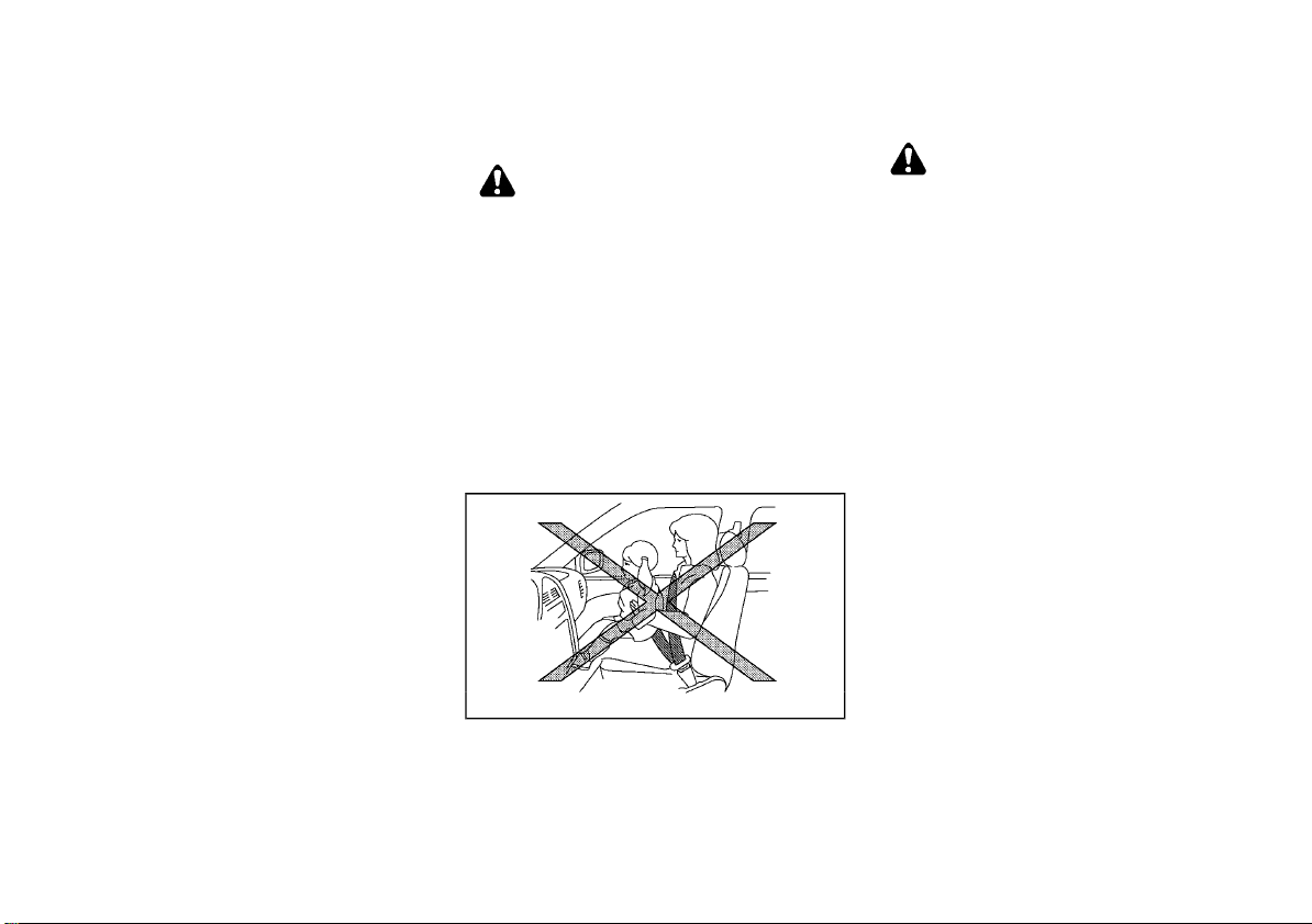
. Seatbelts are designed to bear upon the
bony structure of the body, and should be
worn low across the front of the pelvis or
the pelvis, chest and shoulders, as applicable; wearing the lap section of the belt
across the abdominal area must be
avoided. Serious injury may occur if a
seat belt is not worn properly.
SSS0134A
. Position the lap belt as low and snug as
possible around the hips, not the waist. A
lap belt worn too high could increase the
risk of internal injuries in an accident.
. Do not allow more than one person to use
the same seat belt. Each belt assembly
must only be used by one occupant; it is
dangerous to put a belt around a child
being carried on the occupant’s lap.
. Never carry more people in the vehicle
than there are seat belts.
. Never wear seat belts inside out. Belts
SSS0136A
should not be worn with straps twisted.
Doing so may reduce their effectiveness.
. Seatbelts should be adjusted as firmly as
possible, consistent with comfort, to provide the protection for which they have
been designed. A slack belt will greatly
reduce the protection afforded to the
wearer.
. Every person who drives or rides in this
vehicle should use a seat belt at all times.
Children should be properly restrained in
the rear seat and, if appropriate, in a child
restraint system.
SSS0016
. Do not put the belt behind your back or
under your arm. Always route the
shoulder belt over your shoulder and
across your chest. The belt should be
Safety — seats, seat belts and supplemental restraint system 1-11
Page 34
(34,1)
away from your face and neck, but not
falling off your shoulder. Serious injury
may occur if a seat belt is not worn
properly.
. No modifications or additions should be
made by the user which will either prevent the seat belt adjusting devices from
operating to remove slack, or prevent the
seat belt assembly from being adjusted
to remove slack.
. Care should be taken to avoid contam-
ination of the webbing with polishes, oils
and chemicals, and particularly battery
acid. Cleaning may safely be carried out
using mild soap and water. The belt
should be replaced if webbing becomes
frayed, contaminated or damaged.
. All seat belt assemblies including retrac-
tors and attaching hardware should be
inspected after any collision by a NISSAN
dealer. NISSAN recommends that all seat
belt assemblies in use during a collision
be replaced unless the collision was
minor and the belts show no damage
and continue to operate properly. Seat
belt assemblies not in use during a
collision should also be inspected and,
when necessary, replaced if either damage or improper operation is noted.
. It is essential to replace the entire as-
sembly after it has been worn in a severe
impact even if damage to the assembly is
not obvious.
. Once the pre-tensioner seat belt has
activated, it cannot be reused. It must
be replaced together with the retractor.
Contact a NISSAN dealer.
. Removal and installation of the pre-ten-
sioner seat belt system components
should be done by a NISSAN dealer.
CHILD SAFETY
WARNING:
. Infants and children need special protec-
tion. The vehicle’s seat belts may not fit
them properly. The shoulder belt may
come too close to the face or neck. The
lap belt may not fit over their small
hipbones. In an accident, an improperly
fitted seat belt could cause serious or
fatal injury.
. Always use an appropriate child restraint
system.
Children need adults to help protect them.
They need to be properly restrained. The
proper restraint depends on the child’s size.
Infants and small children
SSS0099
NISSAN recommends that infants and small
children be seated in a child restraint system.
You should choose a child restraint system that
fits your vehicle and the child, and always
follow the manufacturer’s instructions for installation and use.
Large children
WARNING:
. Never allow children to stand or kneel on
any seats.
. Never allow children in the cargo areas
while the vehicle is moving. A child could
be seriously injured in an accident or
sudden stop.
Children who are too large for a child restraint
system should be seated and restrained by the
seat belts that are provided.
If the child’s seating position has a shoulder
belt that fits close to the face or neck, the use
of a booster seat (commercially available) may
help overcome this. The booster seat should
raise the child so that the shoulder belt is
properly positioned across the top, middle
portion of the shoulder and the lap belt is low
on the hips. The booster seat should also fit the
vehicle seat. Once the child has grown so that
the shoulder belt is no longer on or near the
face or neck of the child, use the shoulder belt
without the booster seat. In addition, there are
many types of child restraint systems available
for larger children that should be used for
maximum protection.
PREGNANT WOMEN
NISSAN recommends that pregnant women
use seat belts. The seat belt should be worn
snug, and always position the lap belt as low as
possible around the hips, not the waist. Place
the shoulder belt over your shoulder and
across your chest. Never run the lap/shoulder
belt over your abdominal area. Contact your
doctor for specific recommendations.
1-12 Safety — seats, seat belts and supplemental restraint system
Page 35
(35,1)
INJURED PERSONS
NISSAN recommends that injured persons use
seat belts. Contact your doctor for specific
recommendations.
CENTER MARK ON SEAT BELTS
Selecting correct set of seat belts
SSS0671
The center seat belt buckle is identified by the
CENTER mark. The center seat belt tongue can
be fastened only into the center seat belt
buckle.
THREE-POINT TYPE SEAT BELTS
SSS0292
WARNING:
Every person who drives or rides in this
vehicle should use a seat belt at all times.
Fastening seat belts
WARNING:
The seatback should not be in a reclined
position any more than needed for comfort.
Seat belts are most effective when the
passenger sits well back and straight up in
the seat.
1. Adjust the seat. (See “Seats” (P.1-2).)
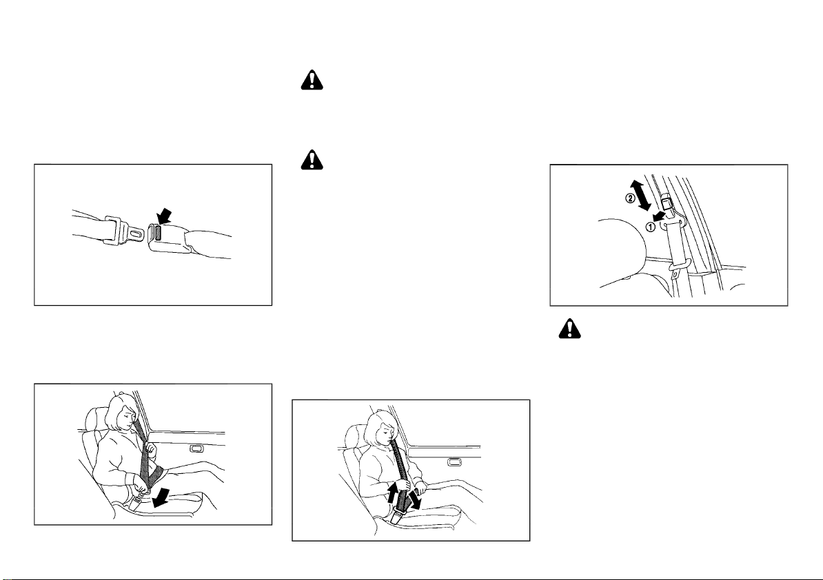
2. Slowly pull the seat belt out of the retractor
and insert the tongue into the buckle until
you hear and feel the latch engage.
.
The retractor is designed to lock during
a sudden stop or on impact. A slow
pulling motion permits the seat belt to
move, and allows you some freedom of
movement in the seat.
.
If the seat belt cannot be pulled from
its fully retracted position, firmly pull
the belt and release it. Then smoothly
pull the belt out of the retractor.
SSS0467
Safety — seats, seat belts and supplemental restraint system 1-13
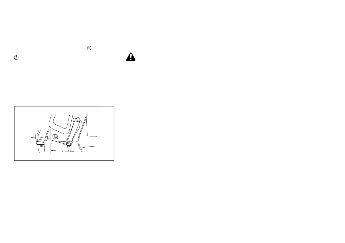
3. Position the lap belt portion low and snug
on the hips as shown.
4. Pull the shoulder belt portion toward the
retractor to take up extra slack. Be sure the
shoulder belt is routed over your shoulder
and is snug across your chest.
Shoulder belt height adjustment (if equipped)
SSS0351A
WARNING:
. The shoulder belt anchor height should
be adjusted to the position best for you.
Failure to do so may reduce the effectiveness of the entire restraint system
and increase the chance or severity of
injury in an accident.
. The shoulder belt should rest on the
middle of the shoulder. It must not rest
against the neck.
. Be sure that the seat belt is not twisted in
any way.
. Be sure that the shoulder belt anchor is
secured by trying to move the shoulder
belt anchor up and down after adjustment.
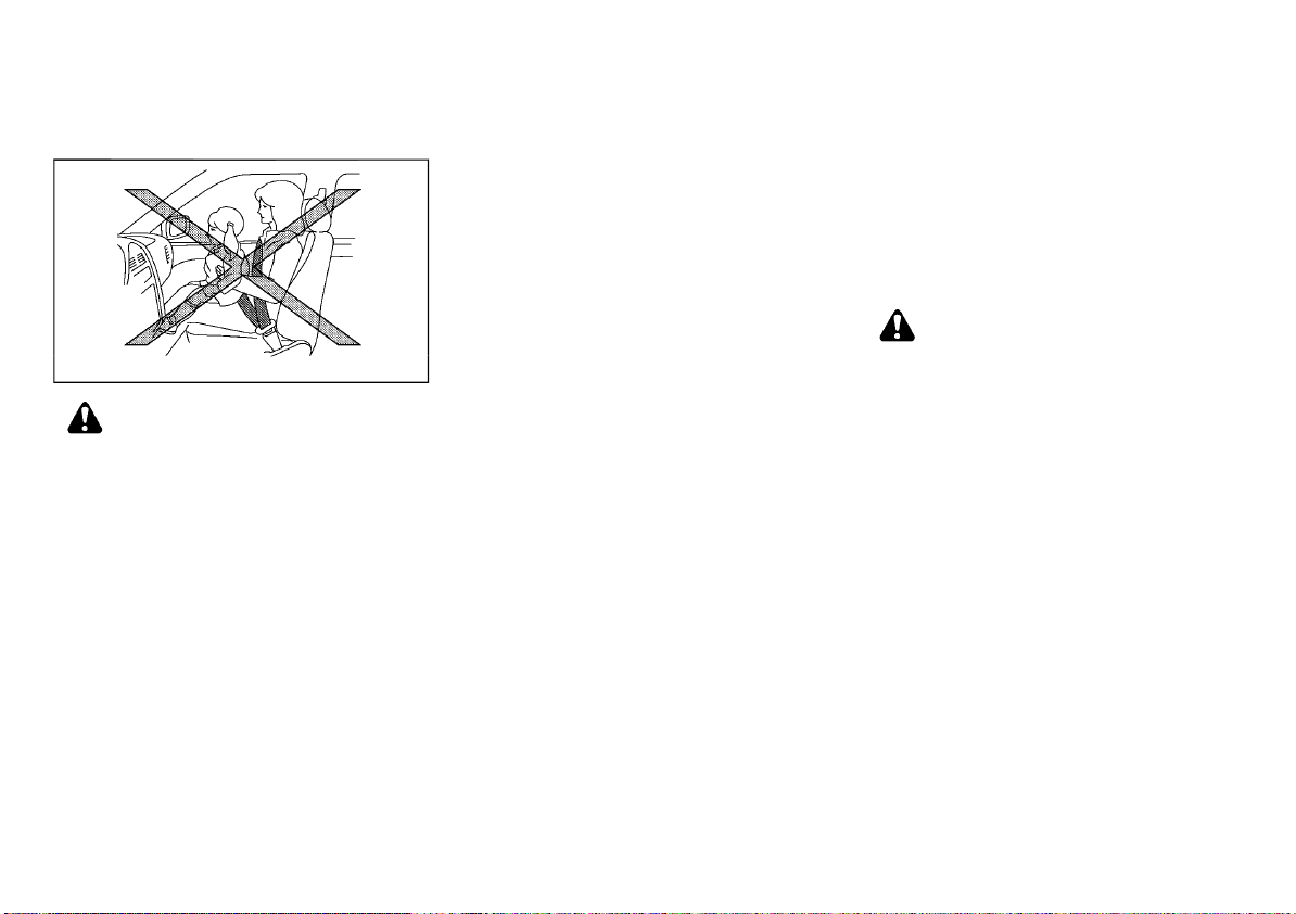
The shoulder belt anchor height should be
Page 36
(36,1)
adjusted to the position best for you.
The belt should be away from your face and
neck, but not falling off your shoulder.
To adjust, pull the release button
the shoulder belt anchor to the proper position
, so that the belt passes over the center of the
shoulder.
Release the button to lock the shoulder belt
anchor into position.
and move
Unfastening seat belts
Push the button on the buckle. The seat belt
automatically retracts.
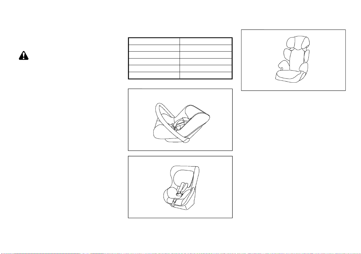
Belt hook (if equipped)
JVR0438X
Seat belt can be hooked on the belt hook.
Automatic locking mode (if equipped)
The front passenger’s and rear three-point seat
belts have an automatic lock mechanism to
use when installing a child restraint system.
This mechanism is referred to as the automatic
locking mode.
If the seat belt is fully extended, the automatic
lock mechanism will be activated and the seat
belt can only retract. The seat belt will not be
able to extend unless the seat belt is fully
retracted once.
To deactivate the automatic locking mode,
detach the seat belt tongue from the buckle
and fully retract the belt to its storing position.
CAUTION:
The automatic locking mode should be used
only for installation of a child restraint
system. During normal seat belt use by a
passenger, the automatic locking mode
should not be activated. The use of the
automatic locking mode by a passenger
may cause uncomfortable seat belt tension.
It can also change the operation of the front
passenger air bag. (See “Supplemental air
bag systems” (P.1-37).)
Checking seat belt operation
Seat belt retractors are designed to lock seat
belt movement:
. When the seat belt is pulled quickly from
the retractor.
. When the vehicle slows down rapidly.
To increase your confidence in the seat belts,
check the operation by grasping the shoulder
belt and pulling forward quickly. The retractor
should lock and restrict further belt movement.
If the retractor does not lock during this check,
contact a NISSAN dealer immediately.
SEAT BELT MAINTENANCE
Periodically check that the seat belt and all the
metal components, such as buckles, tongues,
retractors, flexible wires and anchors, work
properly. If loose parts, deterioration, cuts or
other damage on the seat belt webbing is
found, the entire seat belt assembly should be
replaced.
If dirt builds up in the shoulder belt guide of the
seat belt anchors, the seat belts may retract
slowly. Wipe the shoulder belt guide with a
clean, dry cloth.
To clean the seat belt webbing, apply a mild
soap solution or any solution recommended
for cleaning upholstery or carpet. Then wipe
with a cloth and allow the seat belts to dry in
the shade. Do not allow the seat belts to retract
until they are completely dry.
1-14 Safety — seats, seat belts and supplemental restraint system
Page 37
(37,1)
CHILD RESTRAINTS
PRECAUTIONS ON CHILD RESTRAINT
USAGE
SSS0099
WARNING:
. Infants and small children should always
be placed in an appropriate child restraint while riding in the vehicle. Failure
to use a child restraint can result in
serious injury or death.
. Infants and small children should never
be carried on your lap. It is not possible
for even the strongest adult to resist the
forces of a severe accident. The child
could be crushed between the adult and
parts of the vehicle. Also, do not put the
same seat belt around both your child
and yourself.
. NISSAN recommends that the child re-
straints be installed in the rear seat.
According to accident statistics, children
are safer when properly restrained in the
rear seat than in the front seat.
. Improper use or improper installation of
a child restraint can increase the risk or
severity of injury for both the child and
other occupants of the vehicle and can
lead to serious injury or death in an
accident.
. Follow all of the child restraint manufac-
turer’s instructions for installation and
use. When purchasing a child restraint, be
sure to select one which will fit your child
and vehicle. It may not be possible to
properly install some types of child restraint in your vehicle.
. The direction of the child restraint, either
front-facing or rear-facing, depends on
the type of the child restraint and the size
of the child. Refer to the child restraint
manufacturer’s instructions for details.
. Adjustable seatbacks should be posi-
tioned to ensure full contact between
child restraint and seatback.
. After attaching a child restraint, test it
before you place the child in it. Push it
from side to side and tug it forward to
make sure that it is held securely in place.
The child restraint should not move more
than 25 mm (1 in). If the restraint is not
secure, tighten the belt as necessary, or
install the restraint in another seat and
test it again.
. When the child restraint is not in use,
keep it secured with the ISOFIX child
restraint system or a seat belt to prevent
it from being thrown around in case of a
sudden stop or accident.
. Never install a rear-facing child restraint
on the front passenger’s seat when the
front passenger’s air bag is available.
Supplemental front-impact air bags inflate with great force. A rear-facing child
restraint could be struck by the supplemental front-impact air bags in an accident and could seriously injure or kill your
child.
Safety — seats, seat belts and supplemental restraint system 1-15
. If the seat belt in the position where a
child restraint is installed requires a locking device and if it is not used, injuries
could result from a child restraint tipping
over during normal vehicle braking or
cornering.
. If you install a child restraint system on
the rear seat, move the rear seat to the
rearmost position (for models with sliding seats).
CAUTION:
Remember that a child restraint system left
in a closed vehicle can become very hot.
Check the seating surface and buckles before
placing your child in a child restraint.
NISSAN recommends that infants and small
children be seated in a child restraint. You
should choose a child restraint that fits your
vehicle and always follow the manufacturer’s
instructions for installation and use. In addition,
there are many types of child restraints available for larger children that should be used for
maximum protection.
Page 38
(38,1)
UNIVERSAL CHILD RESTRAINTS FOR
FRONT SEAT AND REAR SEATS (for
Argentina and Europe)
WARNING:
In vehicles equipped with a side air bag
system, do not let any infants or small
children sit in the front passenger’s seat as
the air bag may cause serious injury in case
of deployment during a collision.
NOTE:
Universal child restraints approved to UN
Regulation No.44 (UN R44) or UN Regulation
No.129 (UN R129) are clearly marked “Universal”.
When selecting any child restraint, keep the
following points in mind:
. Choose a child restraint that complies with
the UN R44 or UN R129.
. Place your child in the child restraint and
check the various adjustments to be sure
the child restraint is compatible with your
child. Always follow all of the recommended
procedures.
. Check the child restraint in your vehicle to
be sure it is compatible with vehicle’s seat
belt system.
. Refer to the tables later in this section for a
list of the recommended fitment positions
and the approved child restraints for your
vehicle.
Mass group of child seat
Mass group Child’s weight
Group 0 up to 10 kg
Group 0+ up to 13 kg
Group I 9 to 18 kg
Group II 15 to 25 kg
Group III 22 to 36 kg
Kind of child seats (example):
Child safety seat categories 0 and 0+
Child safety seat categories II and III
JVR0373X
JVR0371X
Child safety seat categories 0+ and I
1-16 Safety — seats, seat belts and supplemental restraint system
JVR0372X
Page 39
(39,1)
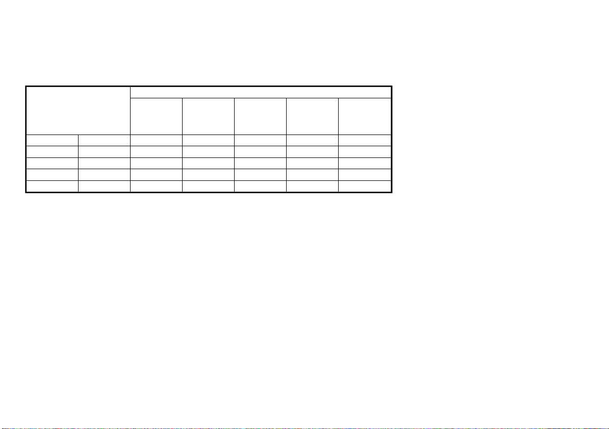
Approved child restraint positions
The following restriction is applied when using child restraints varying by infants weight and
installation position.
Suitability
Mass group
0
0+
I
II
III
X: not suitable for child restraint system
U: suitable for universal category child restraint system approved for this weight group
UF: suitable for forward-facing universal category child restraint system approved for this weight
group
L: suitable for particular child restraints given on attached list or vehicle list of child restraint
manufacturer
*1: If you install a child seat, remove the head restraint.
*2: If you install a child seat on sliding seat, set to most rearward slide position.
<10 kg X X U*2 X
<13 kg X L*2 U/L*2 X
9 - 18 kg X L*2 U*2 X
15 - 25 kg X L*1*2 UF/L*1*2 X
22 - 36 kg X L*1*2 UF/L*1*2 X
Front passenger seat
(Air bag ON)
Front pas-
senger seat
(Air bag
OFF)
Second row
outer seat
Second row
center seat
Third row
seat
X
X
X
X
X
Safety — seats, seat belts and supplemental restraint system 1-17
Page 40
(40,1)
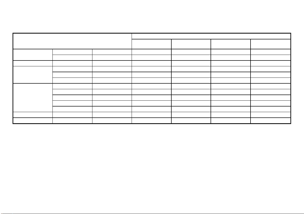
Permissible options for fitting an ISOFIX child restraint
Suitability
Mass group
Carry-cot
0 (<10 kg)
0+ (<13 kg)
I (9 - 18 kg)
II (15 - 25 kg)
III (22 - 36 kg)
X: not suitable for child restraint system
IUF: suitable for universal category forward facing child restraint system approved for this weight group
IL: suitable particular ISOFIX category child restraint system (CRS) given in the below list or vehicle list of child seat manufacturer.
IL*: suitable particular ISOFIX category child restraint system (CRS) given in the vehicle list of child seat manufacturer.
*1: If you install the child seat, remove the head restraint.
F ISO/L1 X X X
G ISO/L2 X X X
E ISO/R1 X IL* X
E ISO/R1 X IL X
D ISO/R2 X IL* X
C ISO/R3 X IL X
D ISO/R2 X IL* X
C ISO/R3 X IL X
B ISO/F2 X IUF X
B1 ISO/F2X X IL*1/IUF X
A ISO/F3 X IUF X
— — X IL*1 X
— — X IL*1 X
Front passenger
seat
Second row outer
seat
Second row center
seat
Third row seat
X
X
X
X
X
X
X
X
X
X
X
X
X
1-18 Safety — seats, seat belts and supplemental restraint system
Page 41
(41,1)
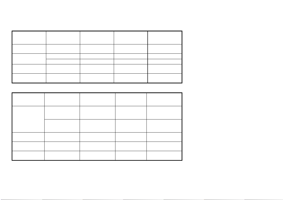
List of Universal recommended child restraints
0+ (<13 kg)
I (9 - 18 kg)
II (15 - 25 kg)
III (22 - 36 kg)
Front passenger
seat
(Air bag OFF)
Maxi Cosi Cabrio
Fix
Römer King plus Römer King plus —
— Römer Duo plus —
Römer Kid fix
(belt mounted)
Römer Kid fix
(belt mounted)
Second row outer
seat
Maxi Cosi Cabrio
Fix
Römer Kid fix
(belt mounted)
Römer Kid fix
(belt mounted)
Second row cen-
List of Semi-universal recommended child restraints
Front passenger
seat
(Air bag OFF)
Maxi Cosi Cabrio
Fix plus
0+ (<13 kg)
I (9 - 18 kg) —
II (15 - 25 kg) —
III (22 - 36 kg) —
Easy Fix
—
Second row outer
seat
Maxi Cosi Cabrio
Fix plus
Easy Fix
Maxi Cosi Cabrio
Fix plus
Easy Fix Base
Maxi Cosi pearl
plus family fix
Römer Kid fix
(ISOFIX mounted)
Römer Kid fix
(ISOFIX mounted)
ter seat
—
—
—
Second row
center seat
—
—
—
—
—
Third row seat
—
—
—
—
—
Third row seat
—
—
—
—
—
Safety — seats, seat belts and supplemental restraint system 1-19
Page 42
(42,1)
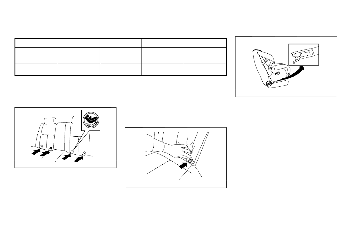
List of approved child restraints
ISOFIX child restraint anchor attachments
Name of CRS Fixture of CRS Facing position
0+ (<13 kg)
I (9 - 18 kg) Römer Duo plus*1
*1: The Fitting arm of the CRS must be engaged with the ISOFIX lower anchor with the 2nd row
seatback in the rearmost position. Then the seatback should be notched forwards to give
good support (0 — 3 notches from the rearmost position) (for models with sliding seats).
Römer Baby safe
plus SHR II+ ISO-
FIX base
ISOFIX CHILD RESTRAINT SYSTEM (for
second row seats)
Your vehicle is equipped with special anchor
points that are used with ISOFIX child restraint
systems.
ISOFIX label location
ISOFIX and sup-
port leg
ISO/F2X top
tether
ISOFIX lower anchor point locations
The ISOFIX anchor points are provided to install
child restraints in the second row outboard
seating positions only. Do not attempt to
install a child restraint in the center seating
position using the ISOFIX anchors.
JVR0351X
The ISOFIX anchors are located at the rear of
the seat cushion near the seatback. A label is
attached to the seatback to help you locate the
ISOFIX anchors.
Rear facing
Front facing
ISOFIX lower anchor location
Category
Semi-universal
Universal
SSS0637
ISOFIX child restraints include two rigid attachments that can be connected to two anchors
located in the seat. With this system, you do not
have to use a vehicle seat belt to secure the
child restraint. Check your child restraint for a
label stating that it is compatible with the
ISOFIX child restraints. This information may
also be in the instructions provided by the child
restraint manufacturer.
ISOFIX child restraints generally require the use
of a top tether strap or other anti-rotation
devices such as support legs. When installing
ISOFIX child restraints, carefully read and follow
the instructions in this manual and those
supplied with the child restraints. (See “Child
restraint installation using ISOFIX” (P.1-21).)
Anchor attachment
SSS0644
1-20 Safety — seats, seat belts and supplemental restraint system
Page 43
(43,1)
CHILD RESTRAINT ANCHORAGE (for
second row seats)
Your vehicle is designed to accommodate a
child restraint system on the second row seat.
When installing a child restraint system, carefully read and follow the instructions in this
manual and those supplied with the child
restraint system.
WARNING:
. Child restraint anchorages are designed
to withstand only those loads imposed
by correctly fitted child restraints. Under
no circumstances are they to be used for
adult seat belts, harnesses or for attaching other items or equipment to the
vehicle. Doing so could damage the child
restraint anchorages. The child restraint
will not be properly installed using the
damaged anchorage, and a child could be
seriously injured or killed in a collision.
. The child restraint top tether strap may
be damaged by contact with the tonneau
cover (if equipped) or items in the luggage area. Remove the tonneau cover
from the vehicle or secure it and any
luggage. Your child could be seriously
injured or killed in a collision if the top
tether strap is damaged.
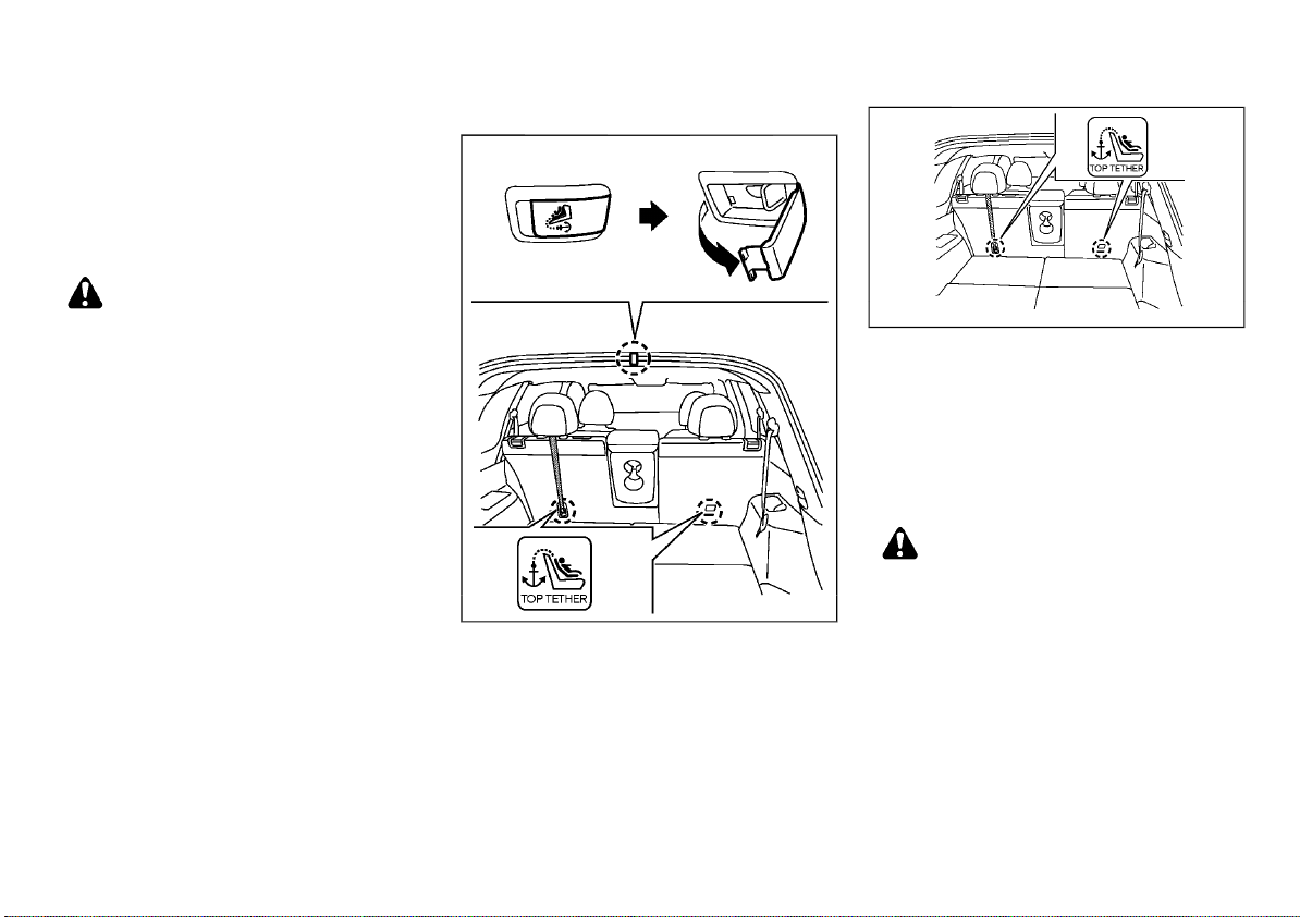
Anchorage location
Type A
JVR0447X
Anchorages are located as illustrated.
Position the top tether strap over the top of the
seatback and secure it to the tether anchorage
that provides the straightest installation. Tighten the tether strap according to the manufacturer’s instruction to remove any slack.
Type B (example)
JVR0448X
CHILD RESTRAINT INSTALLATION USING
ISOFIX
WARNING:
. Attach ISOFIX child restraints only at the
specified locations. For the ISOFIX lower
anchor locations, see “ISOFIX child restraint system (for second row seats)”
(P.1-20). If a child restraint is not secured
properly, your child could be seriously
injured or killed in an accident.
. Do not install child restraints that require
the use of a top tether strap to seating
positions that do not have a top tether
anchor.
. Do not secure a child restraint in the
center rear seating position using the
ISOFIX lower anchors. The child restraint
will not be secured properly.
Safety — seats, seat belts and supplemental restraint system 1-21
Page 44
(44,1)
. Inspect the lower anchors by inserting
your fingers into the lower anchor area
and feeling to make sure there are no
obstructions over the ISOFIX anchors,
such as seat belt webbing or seat cushion
material. The child restraint will not be
secured properly if the ISOFIX anchors
are obstructed.
. Child restraint anchorages are designed
to withstand only those loads imposed
by correctly fitted child restraints. Under
no circumstance are they to be used for
adult seat belts, harnesses or for attaching other items or equipment to the
vehicle. Doing so could damage the child
restraint anchorages. The child restraint
will not be properly installed using the
damaged anchorage, and a child could be
seriously injured or killed in a collision.
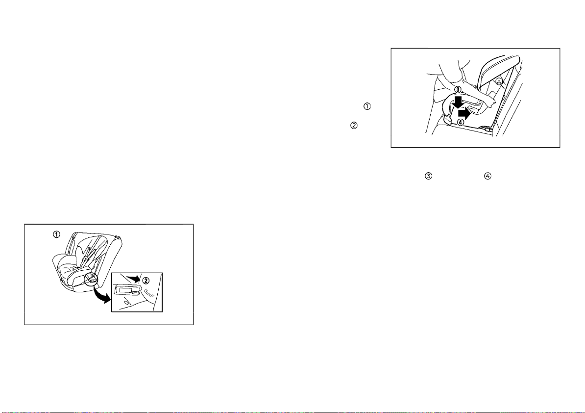
Installation on rear outboard seats
Front-facing:
Be sure to follow the manufacturer’s instructions for the proper use of your child restraint.
Follow these steps to install a front-facing child
restraint on the second row outboard seats
using ISOFIX:
1. Position the child restraint on the seat
2. Secure the child restraint anchor attachments to the ISOFIX lower anchors
3. For Europe and Latin America (Mass
group I-F2X, II, III):
The back of the child restraint should be
secured against the vehicle seatback. The
head restraint should be removed to obtain
the correct child restraint fit. Store the head
restraint in a secure place. Be sure to install
the head restraint when the child restraint
is removed. (See “Head restraints” (P.1-8),
“Universal child restraints for front seat and
rear seats (for Argentina and Europe)” (P.1-
16).)
For Europe and Latin America (except for
Mass group I-F2X, II, III):
Except for Europe and Latin America:
The back of the child restraint should be
secured against the vehicle seat back. If
necessary, adjust or remove the head
restraint to obtain the correct child restraint fit. If the head restraint is removed,
store it in a secure place. Be sure to install
Steps 1 and 2
SSS0646A
the head restraint when the child restraint
is removed. If the seating position does not
have an adjustable head restraint and it is
interfering with the proper child restraint
fit, try another seating position or a different child restraint. (See “Head restraints”
(P.1-8), “Universal child restraints for front
seat and rear seats (for Argentina and
Europe)” (P.1-16).)
1-22 Safety — seats, seat belts and supplemental restraint system
.
.
4. Shorten the rigid attachment to have the
Step 4
SSS0754A
child restraint firmly tightened; press downward
and rearward firmly in the center
of the child restraint with your knee to
compress the vehicle seat cushion and
seatback. Adjustable seatbacks should be
positioned to ensure full contact between
child restraint and seatback.
5. If the child restraint is equipped with a top
tether strap, route the top tether strap and
secure the tether strap to the tether
anchor point. (See “Child restraint anchorage (for second row seats)” (P.1-21).)
6. If the child restraint is equipped with other
anti-rotation devices such as support legs,
use them instead of the top tether strap
following the child restraint manufacturer’s
instructions.
Page 45
(45,1)
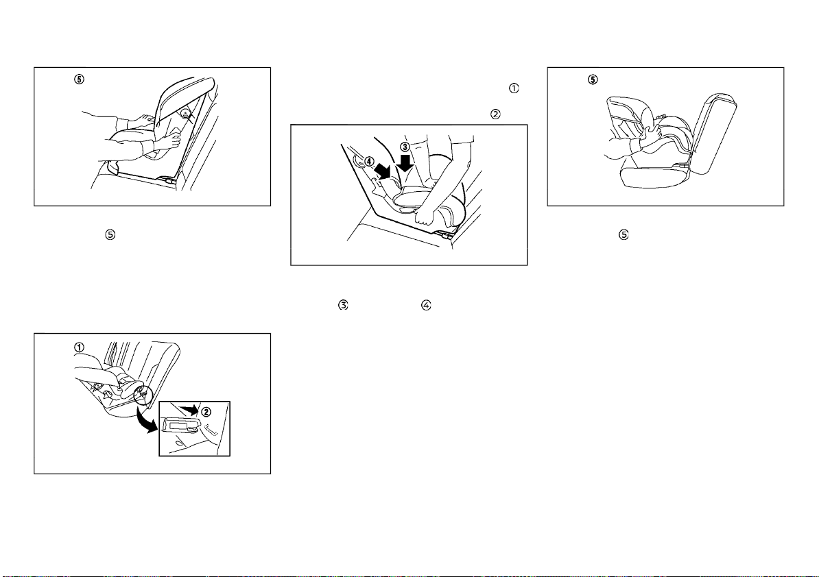
using ISOFIX:
1. Position the child restraint on the seat
2. Secure the child restraint anchor attachments to the ISOFIX lower anchors
.
.
7. Test the child restraint before you place the
child in it
Step 7
. Push the child restraint from
SSS0755A
side to side and tug it forward to make sure
that it is held securely in place.
8. Check to make sure that the child restraint
is properly secured prior to each use. If the
child restraint is loose, repeat steps 3
through 7.
Rear-facing:
Be sure to follow the manufacturer’s instruc-
Steps 1 and 2
SSS0649A
tions for the proper use of your child restraint.
Follow these steps to install a rear-facing child
restraint on the second row outboard seats
3. Shorten the rigid attachment to have the
Step 3
SSS0756A
child restraint firmly tightened; press downward
and rearward firmly in the center
of the child restraint with your hand to
compress the vehicle seat cushion and
seatback.
4. If the child restraint is equipped with a top
tether strap, route the top tether strap and
secure the tether strap to the tether
anchor point. (See “Child restraint anchorage (for second row seats)” (P.1-21).)
5. If the child restraint is equipped with other
anti-rotation devices such as support legs,
use them instead of the top tether strap
following the child restraint manufacturer’s
instructions.
Safety — seats, seat belts and supplemental restraint system 1-23
6. Test the child restraint before you place the
child in it
Step 6
. Push the child restraint from
SSS0757A
side to side and tug it forward to make sure
that it is held securely in place.
7. Check to make sure that the child restraint
is properly secured prior to each use. If the
child restraint is loose, repeat steps 3
through 6.
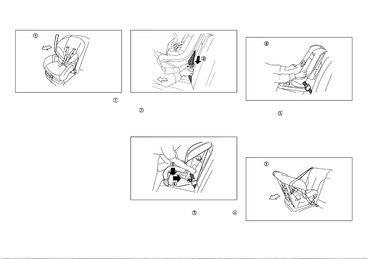
CHILD RESTRAINT INSTALLATION USING
THREE-POINT TYPE SEAT BELT
Installation on rear seats - without
automatic locking mode
Front-facing:
Be sure to follow the manufacturer’s instructions for the proper use of your child restraint.
Follow these steps to install a front-facing child
restraint on the rear seats using three-point
type seat belt without automatic locking mode:
Page 46
(46,1)
between child restraint and seatback.
1. Position the child restraint on the seat .
Front-facing: Step 1
SSS0758A
2. Installation on rear outboard seats (for
Argentina and Europe (Mass group II and
III)):
Remove the head restraint. (See “Head
restraints” (P.1-8), “Universal child restraints
for front seat and rear seats (for Argentina
3. Route the seat belt tongue through the
child restraint and insert it into the buckle
4. To prevent slack in the seat belt webbing, it
is necessary to secure the seat belt in place
with locking devices attached to the child
restraint.
Front-facing: Step 3
until you hear and feel the latch engage.
and Europe)” (P.1-16).)
Installation on rear outboard seats (for
Argentina and Europe (except for Mass
group II and III)):
Installation on rear outboard seats (except for Argentina and Europe):
Adjust the head restraint to its highest
position. (See “Head restraints” (P.1-8), “Universal child restraints for front seat and
rear seats (for Argentina and Europe)” (P.1-
16).)
5. Remove any additional slack from the seat
Front-facing: Step 5
belt; press downward
firmly in the center of the child restraint
with your knee to compress the vehicle
seat cushion and seatback while pulling up
on the seat belt. Adjustable seatbacks
should be positioned to ensure full contact
1-24 Safety — seats, seat belts and supplemental restraint system
SSS0493A
SSS0647A
and rearward
6. Test the child restraint before you place the
child in it
Front-facing: Step 6
. Push the child restraint from
SSS0638A
side to side and tug it forward to make sure
that it is held securely in place.
7. Check to make sure that the child restraint
is properly secured prior to each use. If the
child restraint is loose, repeat steps 3
through 5.
Rear-facing:
Be sure to follow the manufacturer’s instruc-
Rear-facing: Step 1
SSS0759A
tions for the proper use of your child restraint.
Follow these steps to install a rear-facing child
Page 47
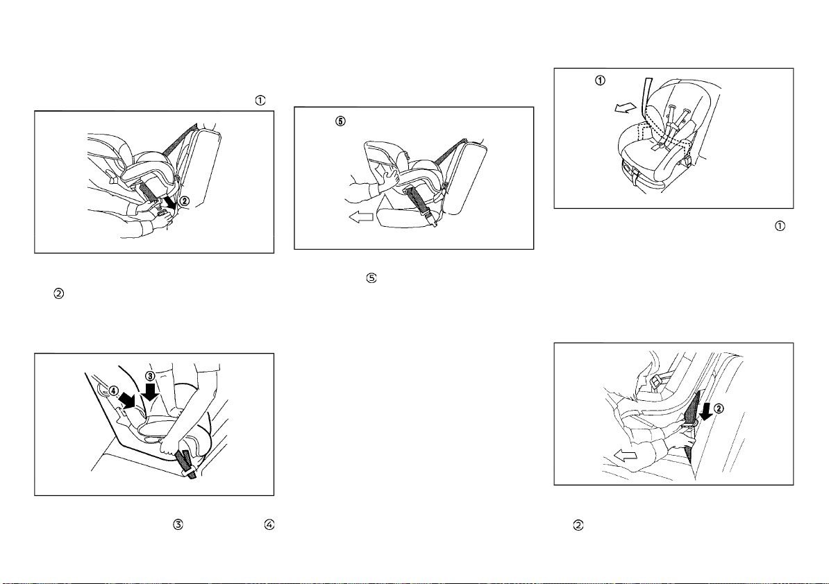
(47,1)
restraint on the rear seats using three-point
type seat belt without automatic locking mode:
1. Position the child restraint on the seat
with your hand to compress the vehicle
seat cushion and seatback while pulling up
.
on the seat belt.
2. Route the seat belt tongue through the
Rear-facing: Step 2
SSS0654A
child restraint and insert it into the buckle
until you hear and feel the latch engage.
3. To prevent slack in the seat belt webbing, it
is necessary to secure the seat belt in place
with locking devices attached to the child
restraint.
4. Remove any additional slack from the seat
belt; press downward
Rear-facing: Step 4
and rearward
SSS0639A
firmly in the center of the child restraint
5. Test the child restraint before you place the
child in it
Rear-facing: Step 5
. Push the child restraint from
SSS0658A
side to side and tug it forward to make sure
that it is held securely in place.
6. Check to make sure that the child restraint
is properly secured prior to each use. If the
child restraint is loose, repeat steps 3
through 5.
Installation on rear seats - with automatic locking mode
Front-facing:
Be sure to follow the manufacturer’s instructions for the proper use of your child restraint.
Follow these steps to install a front-facing child
restraint on the rear seats using three-point
type seat belt with automatic locking mode:
Safety — seats, seat belts and supplemental restraint system 1-25
1. Position the child restraint on the seat .
Front-facing: Step 1
SSS0758A
2. The back of the child restraint should be
secured against the vehicle seatback. If
necessary, adjust or remove the head
restraint to obtain the correct child restraint fit. If the seating position does not
have an adjustable head restraint and it is
interfering with the proper child restraint
fit, try another seating position or a different child restraint.
3. Route the seat belt tongue through the
Front-facing: Step 3
SSS0493A
child restraint and insert it into the buckle
until you hear and feel the latch engage.
Page 48
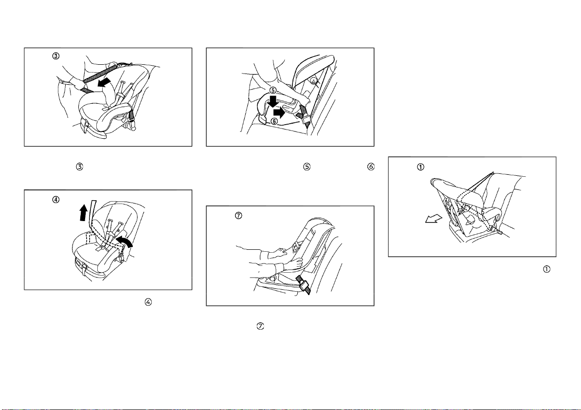
(48,1)
4. Pull the shoulder belt until the belt is fully
extended
Front-facing: Step 4
. At this time, the seat belt
SSS0651A
retractor is in the automatic locking mode
(child restraint mode).
6. Remove any additional slack from the seat
belt; press downward
Front-facing: Step 6
and rearward
SSS0647C
firmly in the center of the child restraint
with your knee to compress the vehicle
seat cushion and seatback while pulling up
on the seat belt.
retractor, the retractor is in the automatic
locking mode.
9. Check to make sure that the child restraint
is properly secured prior to each use. If the
child restraint is loose, repeat steps 4
through 8.
Rear-facing:
Be sure to follow the manufacturer’s instructions for the proper use of your child restraint.
Follow these steps to install a rear-facing child
restraint on the rear seats using three-point
type seat belt with automatic locking mode:
5. Allow the seat belt to retract . Pull up on
Front-facing: Step 5
the shoulder belt to remove any slack in the
belt.
SSS0652A
7. Test the child restraint before you place the
child in it
Front-facing: Step 7
. Push the child restraint from
side to side and tug it forward to make sure
that it is held securely in place.
8. Check that the retractor is in the automatic
locking mode by trying to pull more of the
seat belt out of the retractor. If you cannot
pull any more belt webbing out of the
1-26 Safety — seats, seat belts and supplemental restraint system
SSS0638B
1. Position the child restraint on the seat .
Rear-facing: Step 1
SSS0759A
Page 49
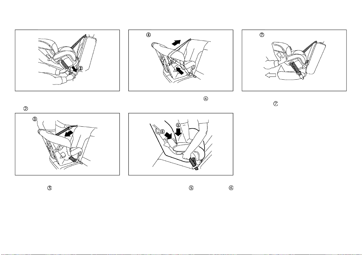
(49,1)
2. Route the seat belt tongue through the
Rear-facing: Step 2
SSS0654A
child restraint and insert it into the buckle
until you hear and feel the latch engage.
3. Pull the shoulder belt until the belt is fully
extended
Rear-facing: Step 3
. At this time, the seat belt
SSS0655A
retractor is in the automatic locking mode
(child restraint mode).
4. Allow the seat belt to retract . Pull up on
Rear-facing: Step 4
SSS0656A
the shoulder belt to remove any slack in the
belt.
5. Remove any additional slack from the seat
belt; press downward
Rear-facing: Step 5
and rearward
SSS0639B
firmly in the center of the child restraint
with your hand to compress the vehicle
seat cushion and seatback while pulling up
on the seat belt.
6. Test the child restraint before you place the
child in it
Rear-facing: Step 6
. Push the child restraint from
SSS0658B
side to side and tug it forward to make sure
that it is held securely in place.
7. Check that the retractor is in the automatic
locking mode by trying to pull more of the
seat belt out of the retractor. If you cannot
pull any more belt webbing out of the
retractor, the retractor is in the automatic
locking mode.
8. Check to make sure that the child restraint
is properly secured prior to each use. If the
child restraint is loose, repeat steps 3
through 7.
Safety — seats, seat belts and supplemental restraint system 1-27
Page 50
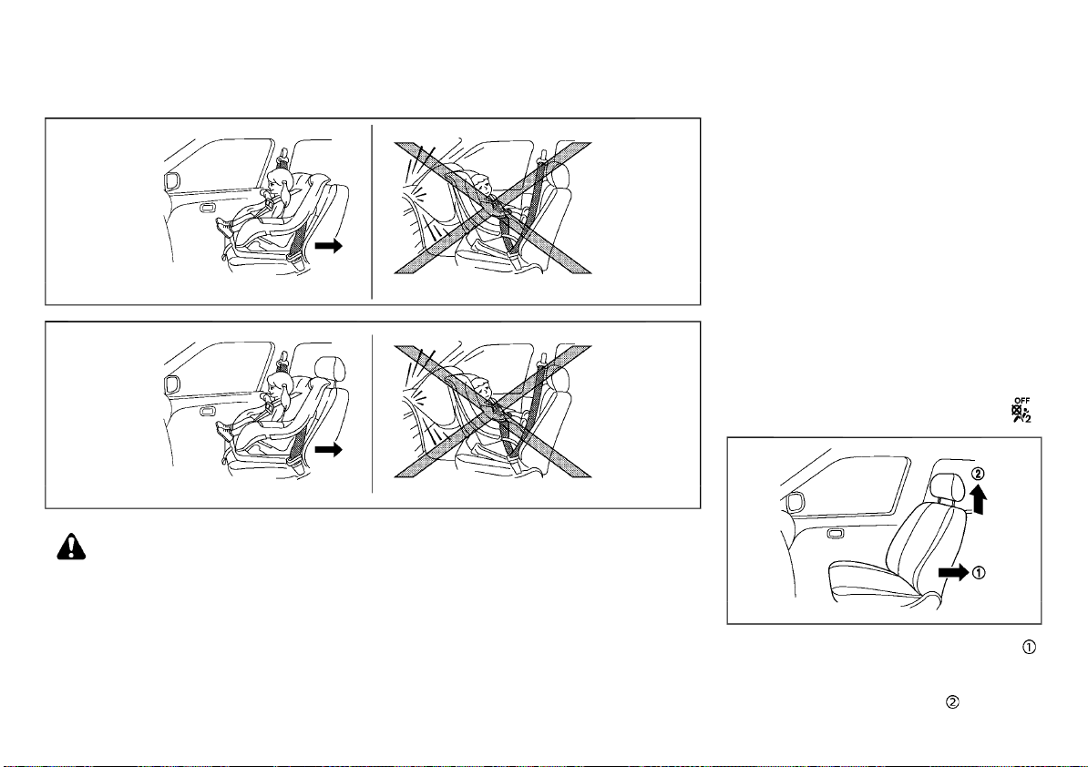
(50,1)
Installation on front passenger’s seat - without automatic locking mode
For Argentina and Europe (Mass group II and III)
For Argentina and Europe (except for Mass group II and III) and except for Argentina and Europe
WARNING:
. Never install a rear-facing child restraint
on the front passenger’s seat when the
front passenger’s air bag is available.
Supplemental front-impact air bags inflate with great force. A rear-facing child
restraint could be struck by the supplemental front-impact air bags in an accident and could seriously injure or kill your
child.
. Never install a child restraint with a top
tether strap on the front seat.
. NISSAN recommends that a child re-
straint be installed on the rear seat.
However, subject to local regulations, if
you must install a child restraint on the
front passenger’s seat, move the passenger’s seat to the rearmost position.
. Child restraints for infants must be used
in the rear-facing direction and therefore
must not be used on the front passen-
JVR0285X
SSS0300A
ger’s seat when the front passenger’s air
bag is available.
. Failure to use the seat belts will result in
the child restraint system not being
properly secured. It could tip over or
otherwise be unsecured and cause injury
to the child in a sudden stop or collision.
Front-facing:
Be sure to follow the manufacturer’s instructions for the proper use of your child restraint.
Follow these steps to install a front-facing child
restraint on the front passenger’s seat using
three-point type seat belt without automatic
locking mode:
1. Turn off the front passenger’s air bag using
the front passenger air bag switch (if
equipped). (See “Supplemental air bag systems” (P.1-37).) Place the ignition switch in
the “ON” position and make sure that the
front passenger air bag status light
(OFF) illuminates. (if equipped)
2. Move the seat to the rearmost position .
Front-facing: Steps 2 and 3
SSS0627
3. For Argentina and Europe (Mass group II
and III):
Remove the head restraint
. (See “Head
1-28 Safety — seats, seat belts and supplemental restraint system
Page 51
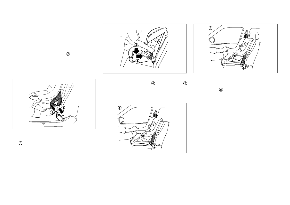
(51,1)
restraints” (P.1-8), “Universal child restraints
for front seat and rear seats (for Argentina
and Europe)” (P.1-16).)
For Argentina and Europe (except for
Mass group II and III):
Except for Argentina and Europe:
Adjust the head restraint
to its highest
position. (See “Head restraints” (P.1-8), “Universal child restraints for front seat and
rear seats (for Argentina and Europe)” (P.1-
16).)
4. Position the child restraint in the seat.
7. Remove any additional slack from the seat
belt; press downward
Front-facing: Step 7
and rearward
SSS0647B
firmly in the center of the child restraint
with your knee to compress the vehicle
seat cushion and seatback while pulling up
on the seat belt.
Front-facing: Step 8 (For Argentina and Europe
(except for Mass group II and III) and except for
8. Test the child restraint before you place the
child in it
Argentina and Europe)
. Push the child restraint from
SSS0302G
side to side and tug it forward to make sure
that it is held securely in place.
9. Check to make sure that the child restraint
is properly secured prior to each use. If the
child restraint is loose, repeat steps 6
through 8.
5. Route the seat belt tongue through the
Front-facing: Step 5
SSS0360C
child restraint and insert it into the buckle
until you hear and feel the latch engage.
6. To prevent slack in the seat belt webbing, it
is necessary to secure the seat belt in place
with locking devices attached to the child
restraint.
Front-facing: Step 8 (for Argentina and Europe
(Mass group II and III))
JVR0286X
Safety — seats, seat belts and supplemental restraint system 1-29
Page 52
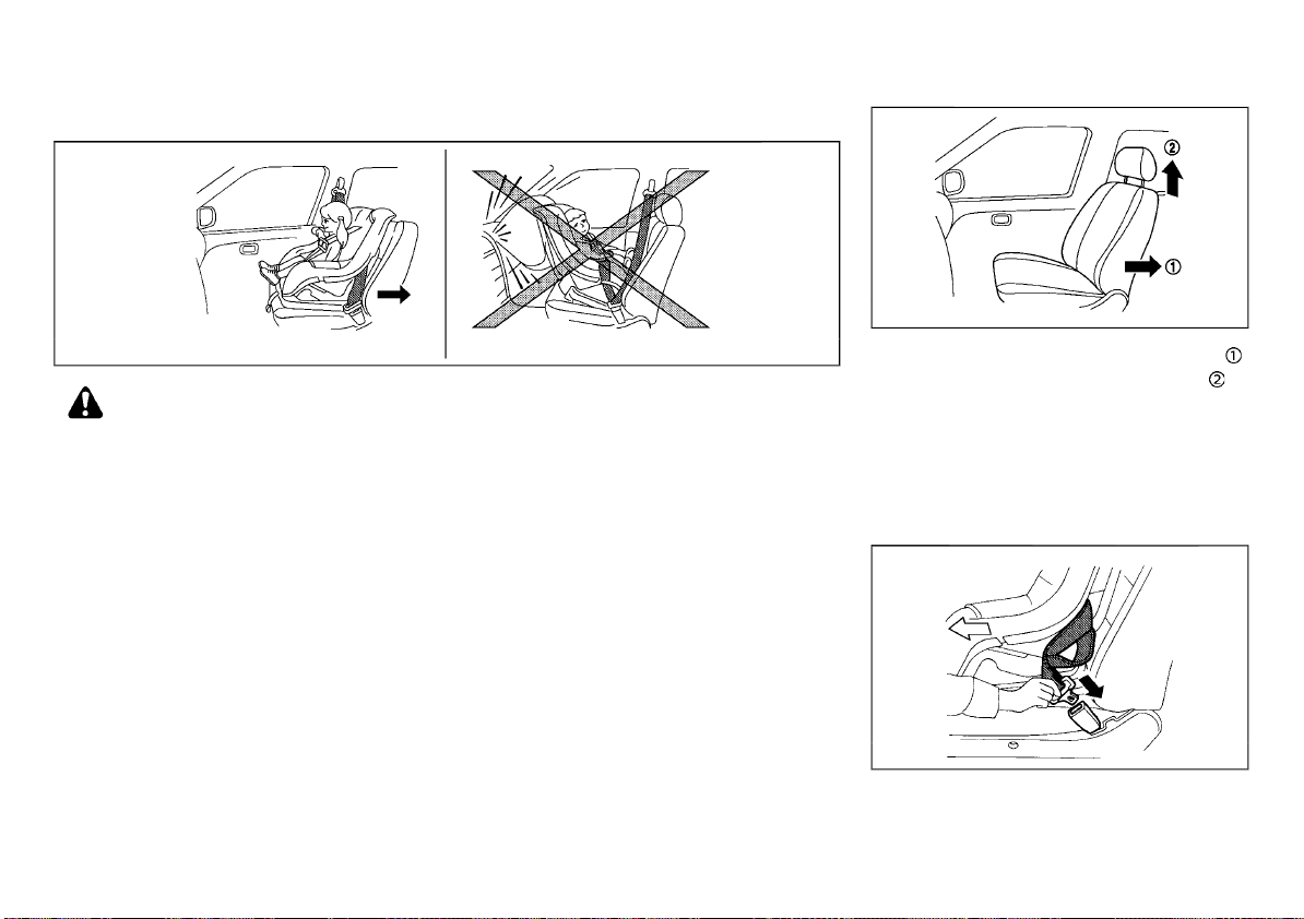
(52,1)
Installation on front passenger’s seat - with automatic locking mode
WARNING:
. Never install a rear-facing child restraint
on the front passenger’s seat when the
front passenger’s air bag is available.
Supplemental front-impact air bags inflate with great force. A rear-facing child
restraint could be struck by the supplemental front-impact air bags in an accident and could seriously injure or kill your
child.
. NISSAN recommends that a child re-
straint be installed on the rear seat.
. Failure to use the seat belts will result in
the child restraint not being properly
secured. It could tip over or otherwise
be unsecured and cause injury to the
child in a sudden stop or collision.
Front-facing:
Be sure to follow the manufacturer’s instructions for the proper use of your child restraint.
Follow these steps to install a front-facing child
restraint on the front passenger’s seat using
three-point type seat belt with automatic locking mode:
However, subject to local regulations, if
you must install a front-facing child
restraint on the front passenger’s seat,
move the passenger’s seat to the rearmost position.
. Never install a child restraint with a top
tether strap on the front seat.
. Child restraint systems for infants must
be used in the rear-facing direction and
therefore must not be used on the front
seat when the front passenger’s air bag is
available.
1-30 Safety — seats, seat belts and supplemental restraint system
JVR0285X
1. Move the seat to the rearmost position .
Front-facing: Steps 1 and 2
SSS0627
2. Adjust or remove the head restraint
obtain the correct child restraint fit. If the
seating position is interfering with the
proper child restraint fit, try another seating position or a different child restraint.
3. Position the front-facing child restraint
system in the front passenger’s seat. It
should be placed on the front-facing direction only.
4. Route the seat belt tongue through the
Front-facing: Step 4
SSS0360B
child restraint and insert it into the buckle
until you hear and feel the latch engage.
to
Page 53
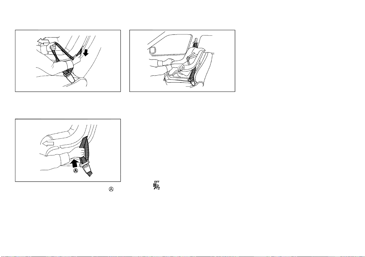
(53,1)
5. Pull the shoulder belt until the entire belt is
Front-facing: Step 5
SSS0361B
extended. At this time, the seat belt retractor is in the automatic locking mode (child
restraint mode).
6. Allow the seat belt to retract. Pull up on
Front-facing: Step 6
SSS0423A
the shoulder belt to remove any slack in the
belt.
7. Test the child restraint before you place the
Front-facing: Step 7
JVR0287X
child in it. Tilt it from side to side. Try to tug
it forward and check if it is held securely in
place.
8. Check that the retractor is in the automatic
locking mode by trying to pull more of the
seat belt out of the retractor. If you cannot
pull any more belt webbing out of the
retractor, the retractor is in the automatic
locking mode.
9. Check to make sure that the child restraint
is properly secured prior to each use. If the
seat belt is not locked, repeat steps 5
through 8.
10. Place the ignition switch in the “ON” position. The front passenger air bag status
light
should illuminate. If this light is
not illuminated, see “Front passenger air
bag status light” (P.1-43). Move the child
restraint to another seating position.
Have the system checked by a NISSAN
dealer.
After the child restraint is removed and the seat
belt is fully retracted, the automatic locking
mode is canceled and returned to the emergency locking mode.
Safety — seats, seat belts and supplemental restraint system 1-31
Page 54

(54,1)
SUPPLEMENTAL RESTRAINT SYSTEM (SRS)
PRECAUTIONS ON SUPPLEMENTAL RESTRAINT SYSTEM (SRS)
This Supplemental Restraint System (SRS) section contains important information concerning the driver’s and passenger’s supplemental
front-impact air bags, supplemental side-impact air bags, supplemental curtain side-impact air bags, supplemental curtain sideimpact and rollover air bags and pre-tensioner
seat belts.
Supplemental front-impact air bag system
This system can help cushion the impact force
to the head and chest area of the driver and/or
front passenger in certain frontal collisions. The
supplemental front-impact air bag is designed
to inflate on the front where the vehicle is
impacted.
This section shows two types of the frontimpact air bag system:
. With Advanced Air Bag System
. Without Advanced Air Bag System
Supplemental side-impact air bag system (if equipped)
This system can help cushion the impact force
to the chest area of the driver and front
passenger in certain side-impact collisions.
The supplemental side-impact air bag is designed to inflate on the side where the vehicle
is impacted.
Supplemental curtain side-impact air
bag system (if equipped)
This system can help cushion the impact force
to the head of the driver and passengers in
front and rear outboard seating positions in
certain side-impact collisions. The supplemental curtain side-impact air bag is designed to
inflate on the side where the vehicle is impacted.
Supplemental curtain side-impact and
rollover air bag system (for Korea)
This system can help cushion the impact force
to the head of the driver and passengers in
front and rear outboard seating positions in
certain side-impact or rollover collisions. In a
side-impact, the supplemental curtain sideimpact and rollover air bag is designed to
inflate on the side where the vehicle is impacted. In a rollover, the supplemental curtain
side-impact and rollover air bags on both sides
are designed to inflate. Under the both sideimpact and rollover situations, the supplemental curtain side-impact and rollover air bags will
remain inflated for a short period of time.
The SRS is designed to supplement the accident protection provided by the driver’s and
passenger’s seat belts and is not designed to
substitute for them. The SRS can help save
lives and reduce serious injuries. However,
inflating air bags may cause abrasions or other
injuries. Air bags do not provide protection to
the lower body. Seat belts should always be
correctly worn and the occupants should always be seated a suitable distance away from
the steering wheel and instrument panel. (See
“Seat belts” (P.1-10).) The air bags inflate quickly
in order to help protect the occupants. The
force of the air bags inflating can increase the
risk of injury if the occupants are too close to,
or are against, the air bag modules during
inflation.
Except for Korea: The air bags will deflate
quickly after deployment.
For Korea: The front and side-impact air bags
will deflate quickly after deployment. The
curtain side-impact air bag will remain inflated
for a while. The curtain side-impact and rollover
air bags will remain inflated for a short period
of time, under both side-impact and rollover
situations.
The SRS operates only when the ignition
switch is in the “ON” position.
When the ignition switch is in the “ON”
position, the SRS air bag warning light
illuminates for about 7 seconds and then
turns off. This indicates that the SRS air bag
system is operational. (See “SRS air bag
warning light” (P.1-36).)
1-32 Safety — seats, seat belts and supplemental restraint system
Page 55
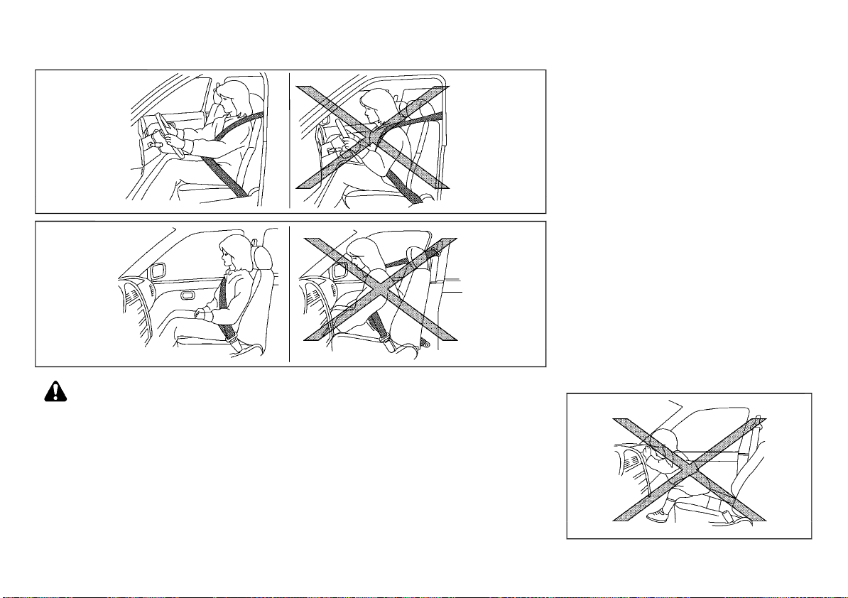
(55,1)
WARNING:
. The supplemental front-impact air bags
ordinarily will not inflate in the event of a
side impact, rear impact, rollover, or lower severity frontal collision. Always wear
the seat belts to help reduce the risk or
severity of injury in accidents.
. The seat belts and the supplemental
front-impact air bags are most effective
when you are sitting well back and upright in the seat. The front-impact air
bags inflate with great force. If you and
your passengers are unrestrained, leaning forward, sitting sideways, or out of
SSS0131A
SSS0132A
position in any way, you and your passengers are at greater risk of injury or
death in an accident. You and your
passengers may also receive serious or
fatal injuries from the supplemental
front-impact air bag if you are up against
it when it inflates. Always sit back against
the seatback and as far away as practical
from the steering wheel or instrument
panel. Always use the seat belts.
. Keep hands on the outside of the steering
wheel. Placing them inside the steering
wheel rim could increase the risk of injury
if the supplemental front air bag inflates.
Safety — seats, seat belts and supplemental restraint system 1-33
. Observe the following precautions for a
model with Advanced Air Bag System:
— The front passenger air bag will not
inflate if the front passenger air bag
status light is lit.
— The driver and front passenger seat
belt buckles are equipped with sensors that detect if the seat belts are
fastened. The advanced air bag system monitors the severity of a collision and seat belt usage then inflates
the air bags. Failure to properly wear
seat belts can increase the risk or
severity of injury in an accident.
— The front passenger seat is equipped
with occupant classification sensors
(weight sensors) that turn the front
passenger air bag OFF under some
conditions. These sensors are only
used in this seat. Failure to be properly seated and wearing the seat belt
can increase the risk or severity of
injury in an accident. (See “Supplemental front-impact air bag system
(with Advanced Air Bag System)” (P.1-
39).)
SSS0006
Page 56

(56,1)
. Never install a rear-facing child restraint
system on the front seat. An inflating
supplemental front-impact air bag could
seriously injure or kill your child. (See
“Child restraints” (P.1-15).)
SSS0007
SSS0008
WARNING:
. Never let children ride unrestrained or
extend their hands or face out of the
window. Do not attempt to hold them in
your lap or arms. Some examples of
dangerous riding positions are shown in
the illustrations.
. Children may be severely injured or killed
when the supplemental front-impact air
SSS0009
bags, supplemental side-impact air bags,
or supplemental curtain side-impact air
bags inflate if they are not properly
restrained.
1-34 Safety — seats, seat belts and supplemental restraint system
SSS0099
SSS0059A
SSS0100
SSS0140
Page 57
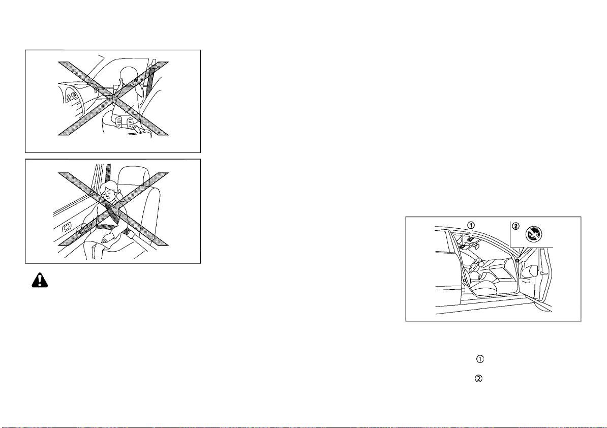
(57,1)
SSS0159
SSS0162
WARNING:
. The supplemental side-impact air bags
ordinarily will not inflate in the event of a
front impact, rear impact, rollover, or
lower severity side collision. Always wear
the seat belts to help reduce the risk or
severity of injury in accidents.
. The supplemental curtain side-impact air
bags ordinarily will not inflate in the
event of a front impact, rear impact,
rollover, or lower severity side collision.
Always wear the seat belts to help reduce
the risk or severity of injury in accidents
(if equipped except for Korea).
. The supplemental curtain side-impact
and rollover air bags ordinarily will not
inflate in the event of a front impact, rear
impact, or lower severity side collision.
Always wear the seat belts to help reduce
the risk or severity of injury in accidents
(for Korea).
. The seat belts and the supplemental
side-impact air bags, supplemental curtain side-impact air bags and supplemental curtain side-impact and rollover
air bags are most effective when you are
sitting well back and upright in the seat.
The supplemental side-impact air bags,
supplemental curtain side-impact air
bags and supplemental curtain side-impact and rollover air bags inflate with
great force. If you and your passengers
are unrestrained, leaning forward, sitting
sideways, or out of position in any way,
you and your passengers are at greater
risk of injury or death in an accident.
. Do not allow anyone to place their hands,
legs, or face near the supplemental sideimpact air bags, supplemental curtain
side-impact air bags and supplemental
curtain side-impact and rollover air bags
on the sides of the seatback of the front
seats or near the side roof rails. Do not
allow anyone sitting in the front seats or
rear outboard seats to extend their hands
out of the windows or lean against the
doors. Some examples of dangerous riding positions are shown in the illustrations.
. When sitting in the rear seats, do not hold
onto the seatback of the front seats. If
the supplemental side-impact air bags,
supplemental curtain side-impact air
bags and supplemental curtain side-impact and rollover air bags inflate, you
Safety — seats, seat belts and supplemental restraint system 1-35
may be seriously injured. Be especially
careful with children, who should always
be properly restrained.
. Do not use seat covers on the front
seatbacks. They may interfere with the
supplemental side-impact air bag inflations.
Pre-tensioner seat belt system
The pre-tensioner seat belt system activates in
conjunction with the supplemental front-impact air bag. Working with the seat belt
retractor and anchor, it helps tighten the seat
belt the instant the vehicle becomes involved in
certain types of collisions, helping to restrain
front seat occupants. (See “Pre-tensioner seat
belt system” (P.1-48).)
Air bag warning labels
SSS1023
Warning labels about the supplemental air bag
system are placed in the vehicle as shown in
the illustration.
The warning label
of the driver’s and/or passenger’s sun visor.
The warning label
the side of the passenger’s side body panel.
is located on the surface
(if equipped) is located on
Page 58
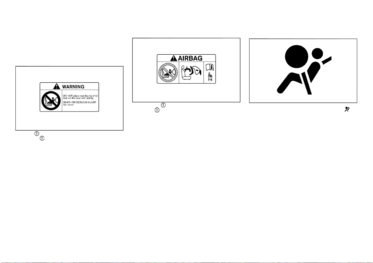
(58,1)
The label(s) warn you not to fit a rear-facing
child restraint system on the front passenger
seat as such a restraint system used in this
position could cause serious injury to the infant
in case of air bag deployment during a collision.
Type A:
Type B:
SRS air bag warning light
The label warns:
Air bag warning label
“NEVER use a rearward facing child restraint on
a seat protected by an ACTIVE AIRBAG in front
The label design varies depending on the
Air bag warning label (sample)
JVR0260X
model.
The label warns:
“Extreme Hazard! Do not use a rearward facing
child restraint on a seat protected by an airbag
in front of it!”
of it, DEATH or SERIOUS INJURY to the CHILD
can occur.”
In vehicles equipped with a front-impact passenger air bag system, use a rear-facing child
restraint system only on the rear seats.
When installing a child restraint system in your
vehicle, always follow the child restraint system
manufacturer’s instructions for installation. For
additional information, see “Child restraints”
(P.1-15).
1-36 Safety — seats, seat belts and supplemental restraint system
JVR0243X
SPA1097
The SRS air bag warning light, displaying in
the meter, monitors the circuits for the air bag
systems, pre-tensioner seat belt systems and
all related wiring.
When the ignition switch is in the “ON” position,
the SRS air bag warning light illuminates for
about 7 seconds and then turns off. This
indicates that the SRS air bag systems are
operational.
If any of the following conditions occur, the air
bag and/or pre-tensioner seat belt systems
need servicing:
. The SRS air bag warning light remains on
after approximately 7 seconds.
. The SRS air bag warning light flashes
intermittently.
. The SRS air bag warning light does not
illuminate at all.
Under these conditions, the air bag and/or pretensioner seat belt systems may not operate
properly. They must be checked and repaired.
Contact a NISSAN dealer immediately.
Page 59
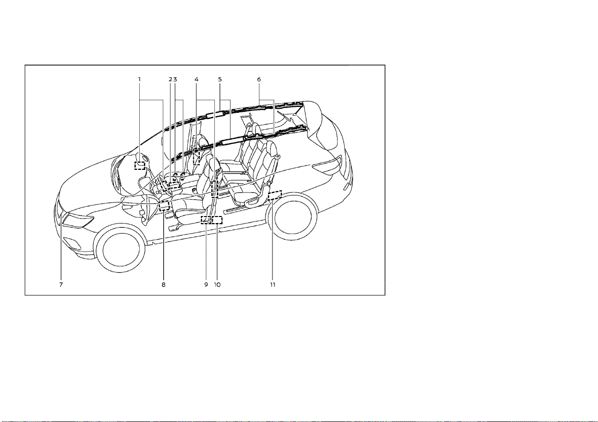
(59,1)
SUPPLEMENTAL AIR BAG SYSTEMS
With Advanced Air Bag System
1. Supplemental front-impact air bag modules (NISSAN Advanced Air Bags)
2. Air bag Control Unit (ACU)
3. Occupant classification sensors (weight
sensors)
4. Supplemental side-impact air bag modules
5. Supplemental curtain side-impact and
rollover supplemental air bags
WAB0010X
6. Supplemental curtain side-impact and
rollover air bag inflators
7. Crash zone sensor
8. Pressure sensors in door (driver’s side
shown; front passenger side similar)
9. Pre-tensioner seat belt retractors (front
seats)
10. Lap outer pre-tensioner
11. Satellite sensors
Safety — seats, seat belts and supplemental restraint system 1-37
Page 60
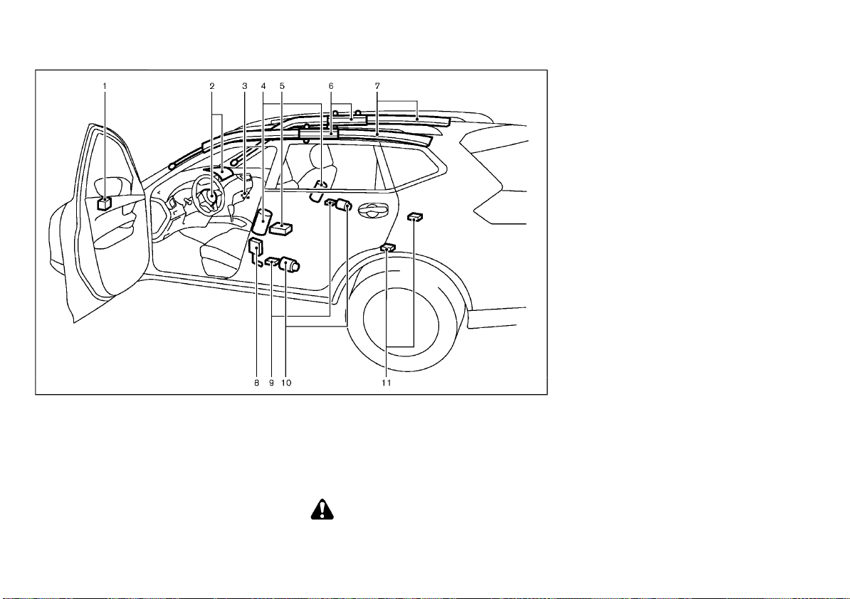
(60,1)
1. Crash zone sensor
2. Supplemental front-impact air bag modules
3. Front passenger air bag switch (if
equipped)
4. Supplemental side-impact air bag modules (if equipped)
5. Air bag Control Unit (ACU)
6. Supplemental curtain side-impact air bag
inflators (if equipped)
1-38 Safety — seats, seat belts and supplemental restraint system
Without Advanced Air Bag System
7. Supplemental curtain side-impact air bag
modules (if equipped)
8. Lap outer pre-tensioner
9. Satellite sensors (if equipped)
10. Pre-tensioner seat belt retractors
11. Satellite sensors (if equipped)
WARNING:
. Do not place any objects on the steering
wheel pad, on the instrument panel, and
near the front door finishers and the
JVR0526X
front seats. Do not place any objects
between any occupants and the steering
wheel pad, on the instrument panel, and
near the front door finishers and the
front seats. Such objects may become
dangerous projectiles and cause injury if
a supplemental air bag inflates.
. Immediately after inflation, several sup-
plemental air bag system components
will be hot. Do not touch them: you may
severely burn yourself.
. No unauthorized changes should be
made to any components or wiring of
the supplemental air bag systems. This is
to prevent accidental inflation of the
supplemental air bags or damage to the
supplemental air bag systems.
. Do not make unauthorized changes to
your vehicle’s electrical system, suspension system, front end structure, and side
panels. This could affect proper operation
of the supplemental air bag systems.
. Tampering with the supplemental air bag
systems may result in serious personal
injury. Tampering includes changes to
the steering wheel and the instrument
panel by placing materials over the steering wheel pad and above, around or on
the instrument panel or by installing
additional trim materials around the
supplemental air bag systems.
. Work around and on the supplemental air
bag systems should be done by a NISSAN
dealer. The SRS wiring should not be
modified or disconnected. Unauthorized
electrical test equipment and probing
devices should not be used on the supplemental air bag systems.
Page 61

(61,1)
. The SRS wiring harness connectors are
yellow and/or orange for easy identification.
When the air bags inflate, a fairly loud noise
may be heard, followed by the release of
smoke. This smoke is not harmful and does
not indicate a fire. Care should be taken not to
inhale it, as it may cause irritation and choking.
Those with a history of a breathing condition
should get fresh air promptly.
Supplemental front-impact air bag
system (with Advanced Air Bag System)
WARNING:
To ensure proper operation of the passenger’s Advanced Air Bag System, observe the
following items.
. Do not allow a passenger in the rear seat
to push or pull on the seatback pocket.
. Do not place heavy loads heavier than 4
kg (9.1 lbs) on the seatback, head restraint or in the seatback pocket.
. Do not store luggage behind the seat that
can press into the seatback.
. Be sure that the front passenger seat
does not contact the rear seat, instrument panel, etc., or the head restraint
does not contact the roof.
. Confirm the operating condition with the
front passenger air bag status light.
. If you notice that the front passenger air
bag status light is not operating in
accordance with the above description,
take your vehicle to a NISSAN dealer to
check the passenger seat Advanced Air
Bag System.
. Until you have confirmed with your deal-
er that your passenger seat Advanced Air
Bag System is working properly, position
the occupants in the rear seating positions.
. Do not position the front passenger seat
so it contacts the rear seat. If the front
seat does contact the rear seat, the air
bag system may determine a sensor
malfunction has occurred and the front
passenger air bag status light may illuminate and the supplemental air bag
warning light may flash.
. Do not place objects with sharp edges on
the seat. Also, do not place heavy objects
on the seat that will leave permanent
impressions in the seat. Such objects can
damage the seat or occupant classification sensors (weight sensors). This can
affect the operation of the air bag system
and result in serious personal injury.
. Do not use water or acidic cleaners (hot
steam cleaners) on the seat. This can
damage the seat or occupant classification sensors. This can also affect the
operation of the air bag system and
result in serious personal injury.
. Removing or modifying the front passen-
ger seat may affect the function of the air
bag system and result in serious personal
injury.
. Modifying or tampering with the front
passenger seat may result in serious
personal injury. For example, do not
change the front seats by placing material on the seat cushion or by installing
additional trim material, such as seat
covers, on the seat that is not specifically
designed to assure proper air bag operation. Additionally, do not stow any objects
Safety — seats, seat belts and supplemental restraint system 1-39
under the front passenger seat or the
seat cushion and seatback. Such objects
may interfere with the proper operation
of the occupant classification sensors.
. The front passenger air bag is designed
to automatically turn OFF under some
conditions. Read this section carefully to
learn how it operates. Proper use of the
seat, seat belt and child restraints is
necessary for most effective protection.
Failure to follow all instructions in this
manual concerning the use of seats, seat
belts and child restraints can increase the
risk or severity of injury in an accident.
This vehicle is equipped with Advanced Air Bag
System for the driver and front passenger
seats. The driver’s supplemental front-impact
air bag is located at the center of the steering
wheel. The passenger’s supplemental frontimpact air bag is located at the instrument
panel above the glove box.
The supplemental front-impact air bag system
is designed to inflate in higher severity frontal
collisions, although it may inflate if the forces in
another type of collision are similar to those of
a higher severity frontal impact. It may not
inflate in certain frontal collisions. Vehicle
damage (or lack of it) is not always an indication of proper supplemental front-impact air
bag system operation.
The Advanced Air Bag System has dual stage
air bag inflators. The system monitors information from the crash zone sensor, the Air bag
Control Unit (ACU), seat belt buckle sensors and
the occupant classification sensors (weight
sensors). Inflator operation is based on the
severity of a collision and seat belt usage for
the driver. For the front passenger, the occupant classification sensors are also monitored.
Based on information from the sensors, only
Page 62
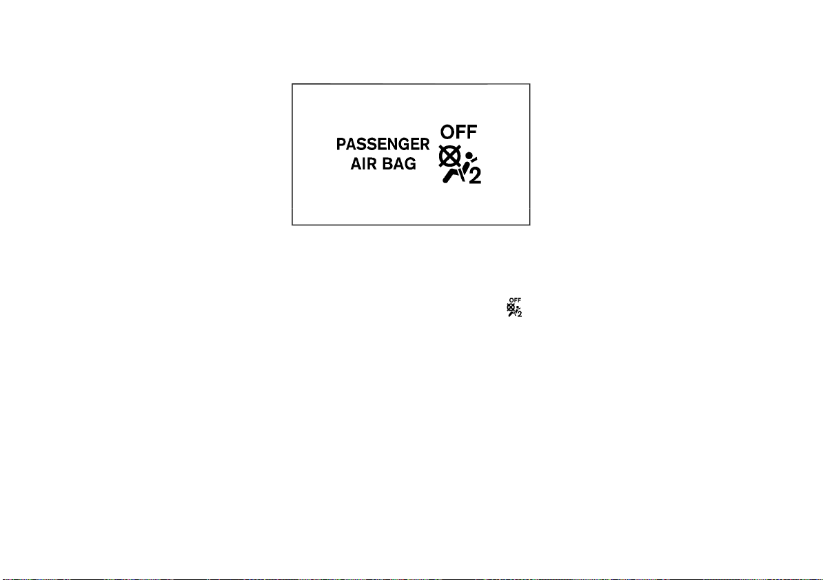
(62,1)
one front air bag may inflate in a crash,
depending on the crash severity and whether
the front occupants are belted or unbelted.
Additionally, the front passenger’s air bag may
be automatically turned OFF under some conditions, depending on the information provided
by the occupant classification sensors. If the
front passenger air bag is OFF, the front
passenger air bag status light will be illuminated. One front air bag inflating does not
indicate improper performance of the system. If
you have any questions about the performance
of your air bag system, please contact NISSAN
or a NISSAN dealer.
Supplemental front air bags, along with the use
of seat belts, help to cushion the impact force
on the head and chest of the front occupants.
They can help save lives and reduce serious
injuries. However, an inflating front air bag may
cause facial abrasions or other injuries. Front
air bags do not provide restraint to the lower
body.
Even with Advanced Air Bag System, seat belts
should be correctly worn and the driver and
passenger seated upright as far as practical
away from the steering wheel or instrument
panel. The supplemental front-impact air bags
inflate quickly in order to help protect the front
occupants. Because of this, the force of the
front air bag inflating can increase the risk of
injury if the occupant is too close to, or is
against, the air bag module during inflation.
The air bag will deflate quickly after a collision.
Front passenger air bag status light:
SSS0676
The front passenger seat is equipped with the
occupant classification sensors (weight sensor)
that turn the front passenger air bag on or off
depending on the weight applied to the front
passenger seat. The status of the front passenger air bag (ON or OFF) is indicated by the
front passenger air bag status light
which is located on the instrument panel.
After the ignition switch is placed in the “ON”
position, the front passenger air bag status
light on the instrument panel illuminates for
about 7 seconds and then turns off or remains
illuminated depending on the front passenger
seat occupied status. The light operates as
follows:
1-40 Safety — seats, seat belts and supplemental restraint system
Page 63
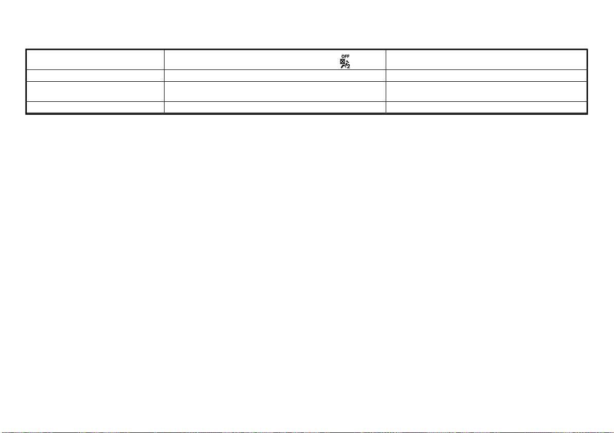
(63,1)
Condition of the front passenger
seat
Empty (unoccupied) ON (illuminated)
Child, Child Restraint, Small Adult
or Baggage
Adult OFF (dark)
In addition to the above, certain objects placed
on the front passenger seat may also cause the
light to operate as described above depending
on their weight.
For additional information related to the normal operation and troubleshooting of this
occupant classification sensor system, please
refer to “Normal operation” (P.1-42) and “Troubleshooting” (P.1-42) in this section.
Front passenger air bag:
The front passenger air bag is designed to
automatically turn OFF when the vehicle is
operated under some conditions as described
below. If the front passenger air bag is OFF, it
will not inflate in a crash. The driver’s air bag
and other air bags in your vehicle are not part
of this system.
The purpose of this system is to help reduce
the risk of injury or death from an inflating air
bag to certain front passenger seat occupants,
such as children, by requiring the air bag to be
automatically turned OFF.
The occupant classification sensors (weight
sensors) are on the seat frame under the front
passenger’s seat and are designed to detect an
occupant and objects on the seat. For example,
if a child is in the front passenger seat, the
Advanced Air Bag System is designed to turn
the front passenger air bag OFF. Also, if a child
restraint is on the seat, the occupant classification sensors can detect it and cause the air bag
to turn OFF.
Front passenger air bag status light (
Front passenger seat adult occupants who are
properly seated and using the seat belt as
outlined in this manual should not cause the
passenger’s air bag to be automatically turned
OFF. For small adults, it may be turned OFF,
however, if the occupant does not sit on the
seat properly (for example, by not sitting upright, by sitting on an edge of the seat, or by
otherwise being out of position), this could
cause the sensors to turn the air bag OFF.
Always be sure to be seated and wearing the
seat belt properly for the most effective protection by the seat belt and supplemental air
bag.
NISSAN recommends that pre-teens and children be properly restrained in a rear seat.
NISSAN also recommends that appropriate
child restraints and booster seats be properly
installed in a rear seat. If this is not possible, the
occupant classification sensors are designed to
operate as described above to turn the front
passenger’s air bag OFF for specified child
restraints. Failing to properly secure child
restrains and to use the automatic locking
mode (child restraint mode) (if equipped) may
allow the restraint to tip or move in an accident
or sudden stop. This can also result in the
passenger’s air bag inflating in a crash instead
of being OFF. (See “Child restraints” (P.1-15) for
proper use and installation.)
If the front passenger’s seat is not occupied,
the passenger’s air bag is designed not to
ON (illuminated)
)
Front passenger air bag status
turned OFF
turned OFF
turned ON
inflate in a crash. However, heavy objects
placed on the seat could result in air bag
inflation, because of the object being detected
by the occupant classification sensors. Other
conditions could also result in air bag inflation,
such as if a child is standing on the seat, or if
two children are on the seat, contrary to the
instructions in this manual. Always be sure that
you and all vehicle occupants are seated and
restrained properly.
Using the front passenger air bag status light,
you can monitor when the front passenger air
bag is automatically turned OFF.
If an adult occupant is in the seat but the front
passenger air bag status light is illuminated
(indicating that the air bag is OFF), it could be
that the person is a small adult, or is not sitting
on the seat properly.
If a child restraint must be used in the front
seat, the front passenger air bag status light
may or may not be illuminated, depending on
the size of the child and the type of child
restraint being used. If the air bag status light is
not illuminated (indicating that the air bag
might inflate in a crash), it could be that the
child restraint or seat belt is not being used
properly. Make sure that the child restraint is
installed properly, the seat belt is used properly
and the occupant is positioned properly. If the
air bag status light is still not illuminated,
reposition the occupant or child restraint in a
rear seat.
Safety — seats, seat belts and supplemental restraint system 1-41
Page 64

(64,1)
If the front passenger air bag status light will
not illuminate even though you believe that the
child restraint, the seat belts and the occupant
are properly positioned, take your vehicle to a
NISSAN dealer. A NISSAN dealer can check the
system status by using a special tool. However,
until you have confirmed with your dealer that
your air bag is working properly, reposition the
occupant or child restraint in a rear seat.
The Advanced Air Bag System and front
passenger air bag status light will take a few
seconds to register a change in the passenger
seat status.
If a malfunction occurs in the front passenger’s
air bag system, the supplemental air bag
warning light
gauges area will blink. Have the system
checked by a NISSAN dealer.
Normal operation:
In order for the occupant classification sensor
system to classify the front passenger based
on weight, please follow the precautions and
steps outlined below:
Precautions:
. Make sure that there are no objects weigh-
ing over 4 kg (9.1 lbs) hanging on the seat or
placed in the seatback pocket.
. Make sure that a child restraint or other
object is not pressing against the rear of
the seatback.
. Make sure that a rear passenger is not
pushing or pulling on the back of the front
passenger seat.
. Make sure that the front passenger seat or
seatback is not forced back against an
object on the seat or floor behind it.
1-42 Safety — seats, seat belts and supplemental restraint system
located in the meter and
. Make sure that there is no object placed
under the front passenger seat.
. Make sure that the front passenger seat
head restraint does not contact the roof
when adjusting the front passenger seat.
Steps:
1. Adjust the seat as outlined. (See “Seats” (P.1-
2).)
2. Make sure there are no objects on your lap.
3. Fasten the seat belt as outlined. (See “Seat
belts” (P.1-10).)
4. Remain in this position for 30 seconds
allowing the system to classify the front
passenger before the vehicle is put into
motion.
5. Ensure proper classification by checking
the front passenger air bag status light.
NOTE:
This vehicle’s occupant classification sensor
system locks the classification during driving
so it is important that you confirm that the
front passenger is properly classified prior to
driving. Also, the occupant classification sensor system may recalculate the weight of the
occupant under some conditions (both while
driving and when stopped), so the front
passenger seat occupant should continue to
remain seated as outlined above.
Troubleshooting:
If you think the front passenger air bag status
light is incorrect:
1. If the light is ON with an adult occupying
the front passenger seat:
. Occupant is a small adult — the air bag light
is functioning as intended. The front passenger air bag is suppressed.
However, if the occupant is not a small adult,
then this may be due to the following conditions that may be interfering with the weight
sensors:
. Occupant is not sitting upright, leaning
against the seatback, and centered on the
seat cushion with his/her feet comfortably
extended to the floor.
. A child restraint or other object pressing
against the rear of the seatback.
. A rear passenger pushing or pulling on the
back of the front passenger seat.
. Forcing the front seat or seatback against
an object on the seat or floor behind it.
. An object placed under the front passenger
seat.
. An object placed between the seat cushion
and center console or between the seat
cushion and the door.
If the vehicle is moving, please come to a stop
when it is safe to do so. Check and correct any
of the above conditions. Restart the vehicle and
wait 1 minute.
NOTE:
A system check will be performed during
which the front passenger air bag status
light will remain lit for about 7 seconds
initially.
If the light is still ON after this, the person
should be advised not to ride in the front
passenger seat and the vehicle should be
checked by a NISSAN dealer as soon as
possible.
2. If the light is OFF with a small adult, child
or child restraint occupying the front
passenger seat.
This may be due to the following conditions that may be interfering with the
weight sensors:
Page 65
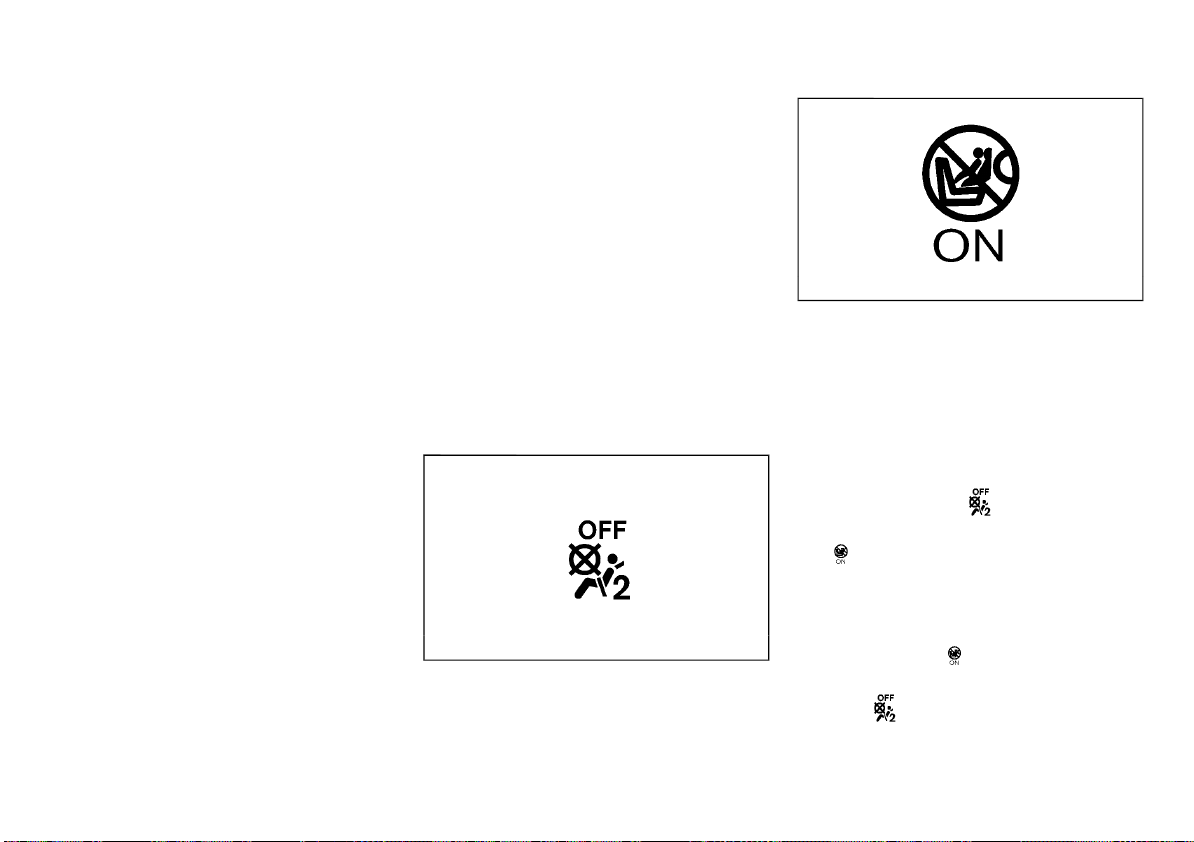
(65,1)
. Small adult or child is not sitting upright,
leaning against the seatback, and centered
on the seat cushion with his/her feet
comfortably extended to the floor.
. The child restraint is not properly installed,
as outlined. (See “Child restraints” (P.1-15).)
. An object weighing over 4 kg (9.1 lbs)
hanging on the seat or placed in the
seatback pocket.
. A child restraint or other object pressing
against the rear of the seatback.
. A rear passenger pushing or pulling on the
back of the front passenger seat.
. Forcing the front seat or seatback against
an object on the seat or floor behind it.
. An object placed under the front passenger
seat.
. An object placed between the seat cushion
and center console.
. The front passenger seat head restraint
contacting the roof.
If the vehicle is moving, please come to a stop
when it is safe to do so. Check and correct any
of the above conditions. Restart the vehicle and
wait 1 minute.
NOTE:
A system check will be performed during
which the front passenger air bag status
light will remain lit for about 7 seconds
initially.
If the light is still OFF after this, the small adult,
child or child restraint should be repositioned in
the rear seat and the vehicle should be
checked by a NISSAN dealer as soon as
possible.
3. If the light is OFF with no front passenger
and no objects on the front passenger
seat, the vehicle should be checked by a
NISSAN dealer as soon as possible.
Supplemental front-impact air bag system (without Advanced Air Bag System)
The driver’s supplemental front-impact air bag
is located at the center of the steering wheel.
The passenger’s supplemental front-impact air
bag is located at the instrument panel above
the glove box.
The supplemental front-impact air bag system
is designed to inflate in higher severity frontal
collisions, although it may inflate if the forces in
another type of collision are similar to those of
a higher severity frontal impact. It may not
inflate in certain frontal collisions. Vehicle
damage (or lack of it) is not always an indication of proper supplemental front-impact air
bag system operation.
Front passenger air bag status light (if
equipped):
JVR0374X
OFF light
Safety — seats, seat belts and supplemental restraint system 1-43
The front passenger air bag status light is
ON light
JVR0264X
located on the instrument panel.
When the ignition switch is placed in the “ON”
position, the front passenger air bag status ON
and OFF lights illuminate and then turn off or
remain on depending on the front passenger
air bag status.
. When the ignition switch is placed in the
“ON” position and the front passenger air
bag is active, the front passenger air bag
status OFF light
will turn off after
about 7 seconds.
The front passenger air bag status ON light
will illuminate and then turn off after 1
minute when the front passenger air bag
switch is in the “ON” position.
. When the ignition switch is placed in the
“ON” position and the front passenger air
bag is inactive, the front passenger air bag
status ON light
will turn off after about
7 seconds.
The front passenger air bag status OFF
light
will illuminate and remain on as
long as the front passenger air bag switch
is in the “OFF” position.
If the front passenger air bag status light
operates in a way other than described above,
Page 66
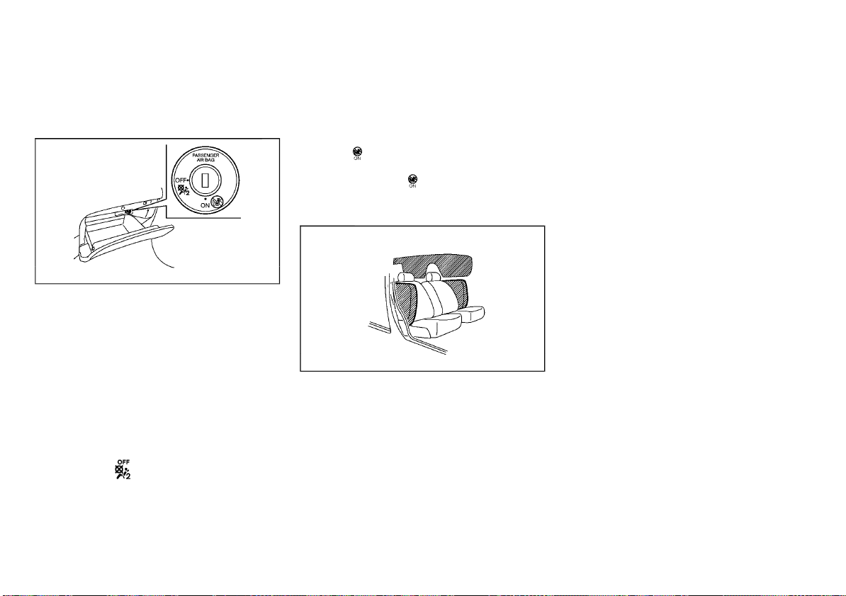
(66,1)
the front passenger air bag may not function
properly. Have the system checked, and if
necessary repaired, by a NISSAN dealer
promptly.
Front passenger air bag switch (if equipped):
JVR0365X
The front passenger air bag can be turned off
with the front passenger air bag switch located
in the glove box.
To turn off the front passenger air bag:
1. Place the ignition switch in the “OFF”
position.
2. Open the glove box and insert the mechanical key into the front passenger air bag
switch. For the mechanical key usage, see
“Keys” (P.3-3).
3. Push and turn the key to the “OFF” position.
4. Place the ignition switch in the “ON” position. The front passenger air bag status
OFF light
on.
To turn on the front passenger air bag:
1. Place the ignition switch in the “OFF”
position.
will illuminate and remain
2. Open the glove box and insert the mechanical key into the front passenger air bag
switch.
3. Push and turn the key to the “ON” position.
4. Place the ignition switch in the “ON” position. The front passenger air bag status ON
light
5. After 1 minute, the front passenger air bag
status ON light
will illuminate.
will turn off.
Supplemental side-impact air bag system (if equipped)
SSS0978
The supplemental side-impact air bag is located at the outside of the front seats’ seatbacks.
The supplemental side-impact air bag system
is designed to inflate in higher severity side
collisions, although it may inflate if the forces in
another type of collision are similar to those of
a higher severity side impact. It may not inflate
in certain side collisions. Vehicle damage (or
lack of it) is not always an indication of proper
supplemental side-impact air bag system operation.
Supplemental curtain side-impact air
bag system (if equipped)
The supplemental curtain side-impact air bag is
located at the roof rails.
The supplemental curtain side-impact air bag
system is designed to inflate in higher severity
side collisions, although it may inflate if the
forces in another type of collision are similar to
those of a higher severity side impact. It may
not inflate in certain side collisions. Vehicle
damage (or lack of it) is not always an indication of proper supplemental curtain side-impact air bag system operation.
Supplemental curtain side-impact and
rollover air bag system (for Korea)
The supplemental curtain side-impact and rollover air bag is located at the roof rails.
The supplemental curtain side-impact and rollover air bag system is designed to inflate in
higher severity side collisions or rollover collisions, although it may inflate if the forces in
another type of collision are similar to those of
a higher severity side impact or near rollover. It
may not inflate in certain side collisions or in
certain rollover collisions. Vehicle damage (or
lack of it) is not always an indication of proper
supplemental curtain side-impact and rollover
air bag system operation.
1-44 Safety — seats, seat belts and supplemental restraint system
Page 67
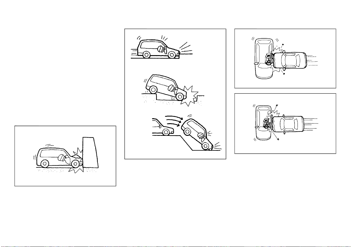
(67,1)
SRS AIR BAG DEPLOYMENT CONDITIONS
The SRS air bags activate in the event of a front
or side impact in which the vehicle occupants
may be severely injured even if they are
wearing the seat belts properly.
They may not activate when the crash energy
is absorbed and/or distributed by the vehicle
body. Vehicle damage (or lack of it) is not
always an indication of proper SRS air bag
system operation.
When the SRS air bag will deploy
Supplemental front-impact air bags:
The supplemental front-impact air bag system
is designed to inflate in higher severity frontal
collisions. Some examples are shown in the
following illustrations.
(supplemental side-impact air bag system)
JVR0161X
JVR0151X
The supplemental front-impact air bag system
will deploy in the event of an impact which
exceeds a 25 km/h (16 MPH) frontal collision
with a solid wall that does not move or deform.
The supplemental front-impact air bag system
may also deploy when the vehicle receives
severe damage to the undercarriage.
JVR0152X
. Hitting a curb, pavement edge or hard
surface at high speed
. Falling into a deep hole or ditch
. Landing hard on the ground after jumping
Supplemental side-impact and curtain sideimpact air bags (if equipped):
The supplemental side-impact and curtain
side-impact air bag systems are designed to
inflate in higher severity side collisions. Some
examples are shown in the following illustrations.
Safety — seats, seat belts and supplemental restraint system 1-45
(supplemental curtain side-impact air bag system)
. The supplemental side-impact and curtain
JVR0162X
side-impact air bags will deploy in the event
of a side impact with a normal passenger
vehicle that exceeds at a speed of 25 km/h
(16 MPH).
Supplemental curtain side-impact and rollover air bags (if equipped):
The supplemental curtain side-impact and rollover air bag systems are designed to inflate in
higher severity side collisions. Some examples
are shown in the following illustrations.
Page 68
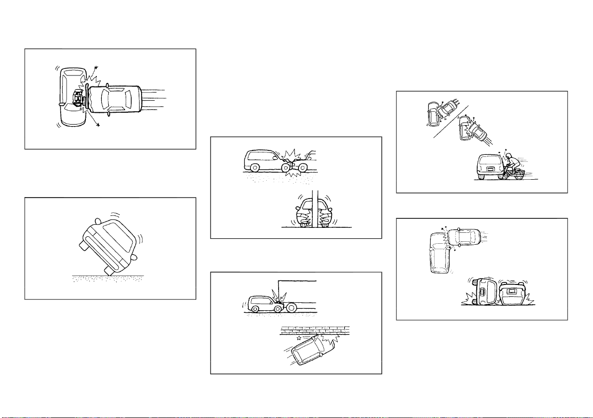
(68,1)
JVR0162X
. The supplemental curtain side-impact and
rollover air bags will deploy in the event of a
side impact with a normal passenger
vehicle that exceeds at a speed of 25
km/h (16 MPH).
JVR0153X
. The supplemental curtain side-impact and
rollover air bags will also deploy when the
vehicle tips up at a certain degree.
When the SRS air bag is unlikely to deploy
The SRS air bags may not deploy in cases
where the impact is not forceful enough to
inflate the SRS air bags.
For example, if the vehicle strikes an object,
such as a parked vehicle or sign pole, which can
move or deform on impact, the SRS air bags are
unlikely to deploy.
Supplemental front-impact air bags:
JVR0154X
. Striking a vehicle of the same class that is
parked
. Crashing into a solid utility pole
. Running under the tail gate of a truck
. A frontal offset impact to the guard rails
Supplemental side-impact and curtain sideimpact air bags (if equipped):
JVR0156X
. A collision from the side at an angle
. A side impact with a two-wheeled vehicle
JVR0157X
. Acollisionfromthesideimpactingthe
vehicle engine room (luggage room)
. Vehicle rollover
1-46 Safety — seats, seat belts and supplemental restraint system
JVR0155X
Page 69
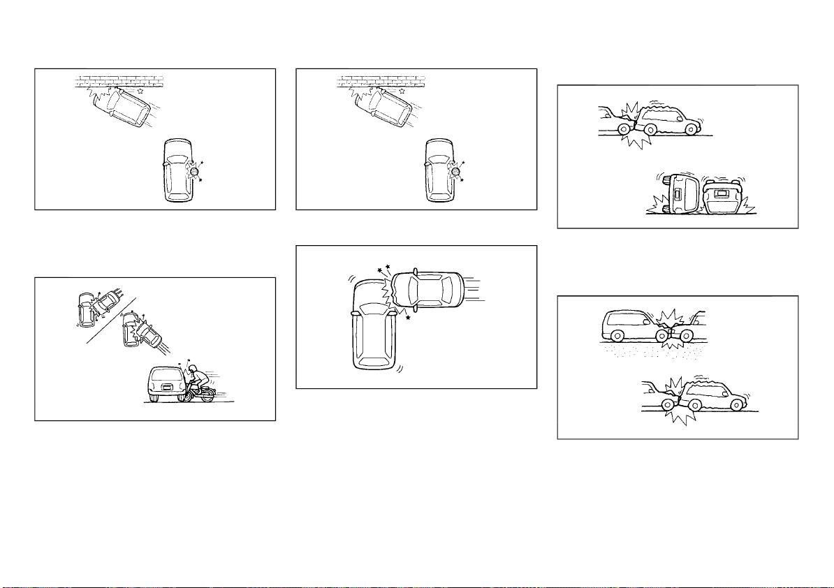
(69,1)
Supplemental front-impact air bags:
JVR0163X
. A frontal offset impact to the guard rails
. A collision with a pole
Supplemental curtain side-impact and rollover air bags (if equipped):
JVR0156X
. A collision from the side at an angle
. A side impact with a two-wheeled vehicle
JVR0163X
. A frontal offset impact to the guard rails
. A collision with a pole
JVR0158X
. Acollisionfromthesideimpactingthe
vehicle engine room
When the SRS air bag will not deploy
Once the SRS air bag has inflated, the air bag
module will not function again if your vehicle
collides with another vehicle or an object.
Other examples where the SRS air bag will not
deploy are shown in the following illustrations.
Safety — seats, seat belts and supplemental restraint system 1-47
JVR0159X
. A collision from the side or rear
. Vehicle rollover
Supplemental side-impact and curtain sideimpact air bags (if equipped):
JVR0160X
. A frontal collision with a parked or moving
vehicle
. A rear collision
Page 70
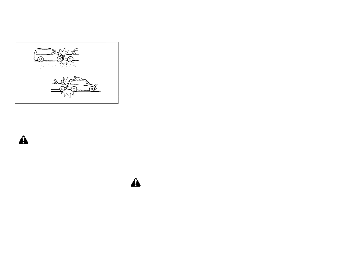
(70,1)
Supplemental side-impact and curtain sideimpact and rollover air bags (if equipped):
JVR0160X
. A frontal collision with a parked or moving
vehicle
. A rear collision
PRE-TENSIONER SEAT BELT SYSTEM
WARNING:
. The pre-tensioner seat belt cannot be
reused after activation. It must be replaced together with the retractor and
buckle as a unit.
. If the vehicle becomes involved in a
collision but the pre-tensioner is not
activated, be sure to have the pre-tensioner system checked and, if necessary,
replaced by a NISSAN dealer.
. No unauthorized changes should be
made to any components or wiring of
the pre-tensioner seat belt system. This
is to prevent accidental activation of the
pre-tensioner seat belt or damage to the
pre-tensioner seat belt system.
. Work around or on the pre-tensioner seat
belt system should be done by a NISSAN
dealer. The SRS wiring should not be
modified or disconnected. Unauthorized
electrical test equipment and probing
devices should not be used on the pretensioner seat belt system.
. If you need to dispose of the pre-ten-
sioner seat belt system, or scrap the
vehicle, contact a NISSAN dealer. Correct
pre-tensioner disposal procedures are
set forth in the appropriate NISSAN Service Manual. Incorrect disposal procedures could cause personal injury.
The pre-tensioner is encased with the front
seat belt’s retractor and anchor. These seat
belts are used the same as conventional seat
belts.
When the pre-tensioner seat belt activates, a
fairly loud noise may be heard, followed by the
release of smoke. This smoke is not harmful
and does not indicate a fire. Care should be
taken not to inhale it, as it may cause irritation
and choking. Those with a history of a breathing condition should get fresh air promptly.
REPAIR AND REPLACEMENT PROCEDURE
WARNING:
. Once the air bags have been inflated, the
air bag modules will not function and
must be replaced. The air bag modules
must be replaced by a NISSAN dealer. The
inflated air bag modules cannot be repaired.
. The air bag systems should be inspected
by a NISSAN dealer if there is any damage
to the front end portion of the vehicle.
. If you need to dispose of the SRS or scrap
the vehicle, contact a NISSAN dealer.
Correct disposal procedures are set forth
in the appropriate NISSAN Service Manual. Incorrect disposal procedures could
cause personal injury.
The air bags and pre-tensioner seat belts are
designed to activate on a one-time-only basis.
As a reminder, unless the SRS air bag warning
light is damaged, the SRS air bag warning light
remains illuminated after inflation has occurred. The repair and replacement of the SRS
should be done only by a NISSAN dealer.
When maintenance work is required on the
vehicle, information about the air bags, pretensioner seat belts and related parts should
be pointed out to the person performing the
maintenance. The ignition switch should always be in the “LOCK” position when working
under the hood or inside the vehicle.
1-48 Safety — seats, seat belts and supplemental restraint system
Page 71

(71,1)
2 Instruments and controls
Cockpit ...................................................................................................................... 2-3
Left-Hand Drive (LHD) model ........................................................... 2-3
Right-Hand Drive (RHD) model ....................................................... 2-5
Instrument panel .............................................................................................. 2-7
Left-Hand Drive (LHD) model ........................................................... 2-7
Right-Hand Drive (RHD) model ....................................................... 2-8
Meters and gauges ......................................................................................... 2-9
Speedometer and odometer ........................................................... 2-9
Tachometer ................................................................................................ 2-10
Engine coolant temperature gauge ....................................... 2-10
Fuel gauge ................................................................................................... 2-11
Instrument brightness control .................................................... 2-11
Continuously Variable Transmission (CVT)/Dual
Clutch Transmission (DCT) position indicator
(if equipped) ................................................................................................ 2-11
Warning lights, indicator lights and
audible reminders ......................................................................................... 2-12
Checking lights ........................................................................................ 2-13
Warning lights ........................................................................................... 2-13
Indicator lights ......................................................................................... 2-17
Audible reminders ................................................................................. 2-20
Vehicle information display ................................................................... 2-21
How to use the vehicle information display .................... 2-21
Startup display ......................................................................................... 2-22
Settings .......................................................................................................... 2-22
Vehicle information display warnings
and indicators ........................................................................................... 2-30
Oil control system (if equipped) ................................................. 2-36
Trip computer ........................................................................................... 2-37
Clock and outside air temperature ......................................... 2-40
Intelligent Driver Alertness (if equipped) ............................. 2-40
Traffic Sign Recognition (if equipped) ................................... 2-41
Headlight and turn signal switch .................................................... 2-43
Headlight switch .................................................................................. 2-43
Headlight aiming control .............................................................. 2-46
Battery saver system ....................................................................... 2-54
Adaptive Front lighting System (AFS)
(if equipped) ............................................................................................. 2-54
Headlight cleaner (if equipped) ................................................ 2-54
Turn signal switch .............................................................................. 2-54
Fog light switch ............................................................................................. 2-55
Front fog lights (if equipped) ..................................................... 2-56
Rear fog light (if equipped) .......................................................... 2-56
Wiper and washer switch ....................................................................... 2-57
Windshield wiper and washer switch ................................. 2-57
Rain-sensing auto wiper system (if equipped) ............ 2-58
Rear window wiper and washer switch ........................... 2-59
Defogger switch ............................................................................................ 2-60
Horn ......................................................................................................................... 2-60
Heated steering wheel (if equipped) ............................................. 2-61
Windows ............................................................................................................... 2-61
Power windows .................................................................................... 2-61
Sunroof (if equipped) ................................................................................. 2-63
Automatic sunroof and sunshade ........................................ 2-63
Power outlets ................................................................................................... 2-64
USB (Universal Serial Bus) charging connector
(if equipped) ............................................................................................. 2-65
Ashtrays and cigarette lighter (if equipped) ........................... 2-65
Ashtray ......................................................................................................... 2-65
Cigarette lighter ................................................................................... 2-66
Storage .................................................................................................................. 2-66
Glove box ................................................................................................... 2-66
Console box ............................................................................................. 2-66
Sunglasses holder ............................................................................... 2-66
>
Page 72

(72,1)
Cup holders ................................................................................................ 2-67
Soft bottle holders ................................................................................ 2-68
Card holder ................................................................................................. 2-68
Luggage hooks ........................................................................................ 2-69
Luggage compartment (if equipped) ..................................... 2-69
Coat hook (if equipped) ................................................................... 2-71
Tonneau cover (if equipped) ......................................................... 2-72
Roof rack (if equipped) .............................................................................. 2-72
Sun visors ............................................................................................................. 2-73
Type A ............................................................................................................. 2-73
Type B ............................................................................................................. 2-73
Interior lights ..................................................................................................... 2-74
Interior light switch .............................................................................. 2-74
Console light .............................................................................................. 2-74
Map lights .................................................................................................. 2-74
Room light (if equipped) ................................................................ 2-75
Rear personal lights (if equipped) .......................................... 2-75
Vanity mirror light (if equipped) .............................................. 2-75
Luggage room light .......................................................................... 2-75
Battery saver system ....................................................................... 2-75
HomeLink® Universal Transceiver (if equipped) ................... 2-76
Programming HomeLink® ............................................................ 2-76
Operating the HomeLink®
Universal Transceiver ....................................................................... 2-77
Programming troubleshooting ................................................ 2-77
Clearing the programmed information ............................. 2-77
Reprogramming a single HomeLink® button ............... 2-77
If your vehicle is stolen ................................................................... 2-77
Page 73
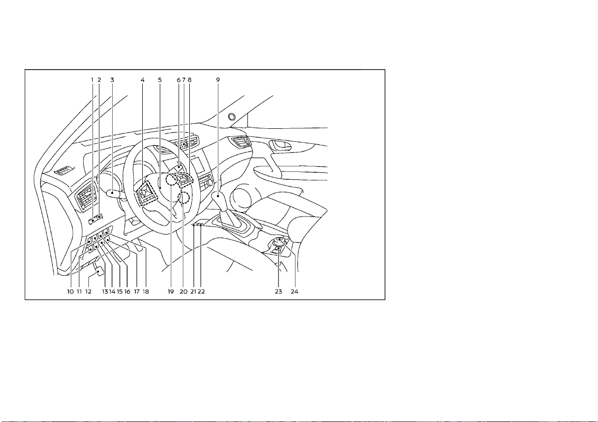
(73,1)
COCKPIT
LEFT-HAND DRIVE (LHD) MODEL
1. Instrument brightness control switch
2. TRIP RESET switch
3. Headlight and turn signal switch/Fog light
switch*
4. Steering-wheel-mounted controls (left
side)
— Audio control* or Navigation System*
— Vehicle information display control
— Bluetooth® Hands-Free Phone System
(without navigation)*
— Bluetooth® Hands-Free Phone System
(with navigation)*
— Voice recognition system switch*
5. Steering wheel
— Horn
6. Wiper and washer switch
7. Hazard indicator flasher switch
WAA0060X
8. Steering-wheel-mounted controls (right
side)
— Cruise control switches*
— Intelligent Cruise Control (ICC) system
switches*
— Speed limiter switches*
— Bluetooth® Hands-Free Phone System
(without navigation)*
— Bluetooth® Hands-Free Phone System
(with navigation)*
— Voice recognition system switch*
9. Shift lever
—Continuously Variable Transmission
(CVT)
— Dual Clutch Transmission (DCT)
— Manual Transmission (MT)
10. Vehicle Dynamic Control (VDC) OFF switch
or Electronic Stability Program (ESP) OFF
switch
11. Heated steering wheel switch* or Headlight aiming control switch*
12. Parking brake (Pedal type)*
13. Headlight cleaner switch* or Intelligent
4x4 LOCK switch (for Korea)*
14. Lane Departure Warning (LDW) switch* or
Intelligent Lane Intervention switch*
15. Stop/Start OFF switch* or SPORT mode
switch*
16. Power back door switch*
17. ECO switch*
18. Power back door main switch* or Fuelfiller lid opener switch*
19. Push-button ignition switch (model with
Intelligent Key system)*
20. Ignition switch (model without Intelligent
Key system)*
Instruments and controls 2-3
Page 74

(74,1)
21. Parking brake (Switch type)*
22. Automatic brake hold switch*
23. Hill descent control switch*
24. Intelligent 4x4 mode switch*
*: if equipped
2-4 Instruments and controls
Page 75
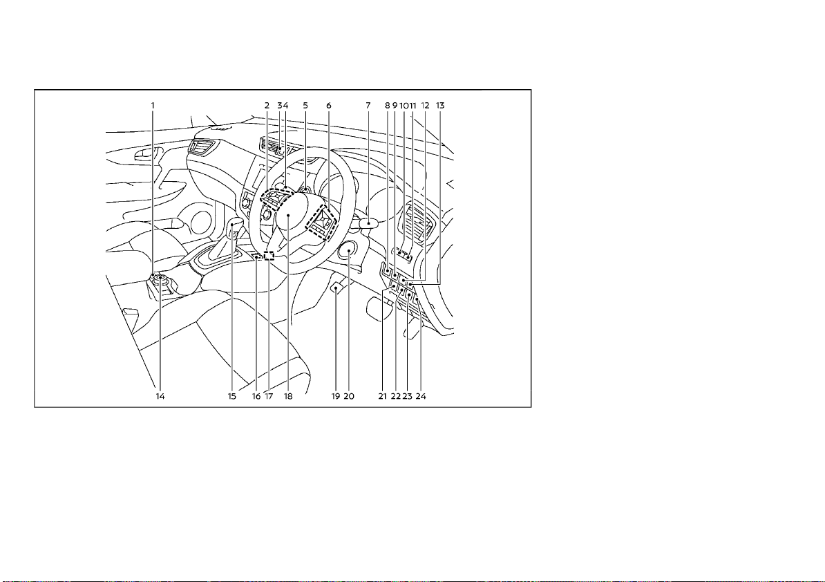
(75,1)
RIGHT-HAND DRIVE (RHD) MODEL
1. Hill descent control switch*
2. Steering-wheel-mounted controls (left
side)
— Audio control* or Navigation System*
— Vehicle information display control
— Bluetooth® Hands-Free Phone System
(without navigation)*
— Bluetooth® Hands-Free Phone System
(with navigation)*
WAA0058X
— Voice recognition system switch*
3. Hazard indicator flasher switch
4. Headlight and turn signal switch/Fog light
switch* or Wiper and washer switch
5. Push-button ignition switch (model with
Intelligent Key system)*
6. Steering-wheel-mounted controls (right
side)
— Cruise control switches*
— Intelligent Cruise Control (ICC) system
switches*
— Speed limiter switches*
— Bluetooth® Hands-Free Phone System
(without navigation)*
— Bluetooth® Hands-Free Phone System
(with navigation)*
— Voice recognition system switch*
7. Wiper and washer switch or Headlight
and turn signal switch/Fog light switch*
8. Power back door main switch*
9. Power back door switch*
10. Instrument brightness control switch
11. TRIP RESET switch
12. Lane Departure Warning (LDW) switch* or
Intelligent Lane Intervention switch*
13. Vehicle Dynamic Control (VDC) OFF switch
or Electronic Stability Program (ESP) OFF
switch
14. Intelligent 4x4 mode switch*
15. Shift lever
—Continuously Variable Transmission
(CVT)
— Dual Clutch Transmission (DCT)
— Manual Transmission (MT)
16. Automatic brake hold switch*
17. Parking brake (Switch type)*
18. Steering wheel
— Horn
19. Parking brake (Pedal type)*
20. Ignition switch (model without Intelligent
Key system)*
21. ECO switch* or Stop/Start or Idling Stop
OFF switch*
Instruments and controls 2-5
Page 76

(76,1)
22. Stop/Start or Idling Stop OFF switch*
23. ECO switch*
24. Heated steering wheel switch* or Headlight aiming control switch*
*: if equipped
2-6 Instruments and controls
Page 77
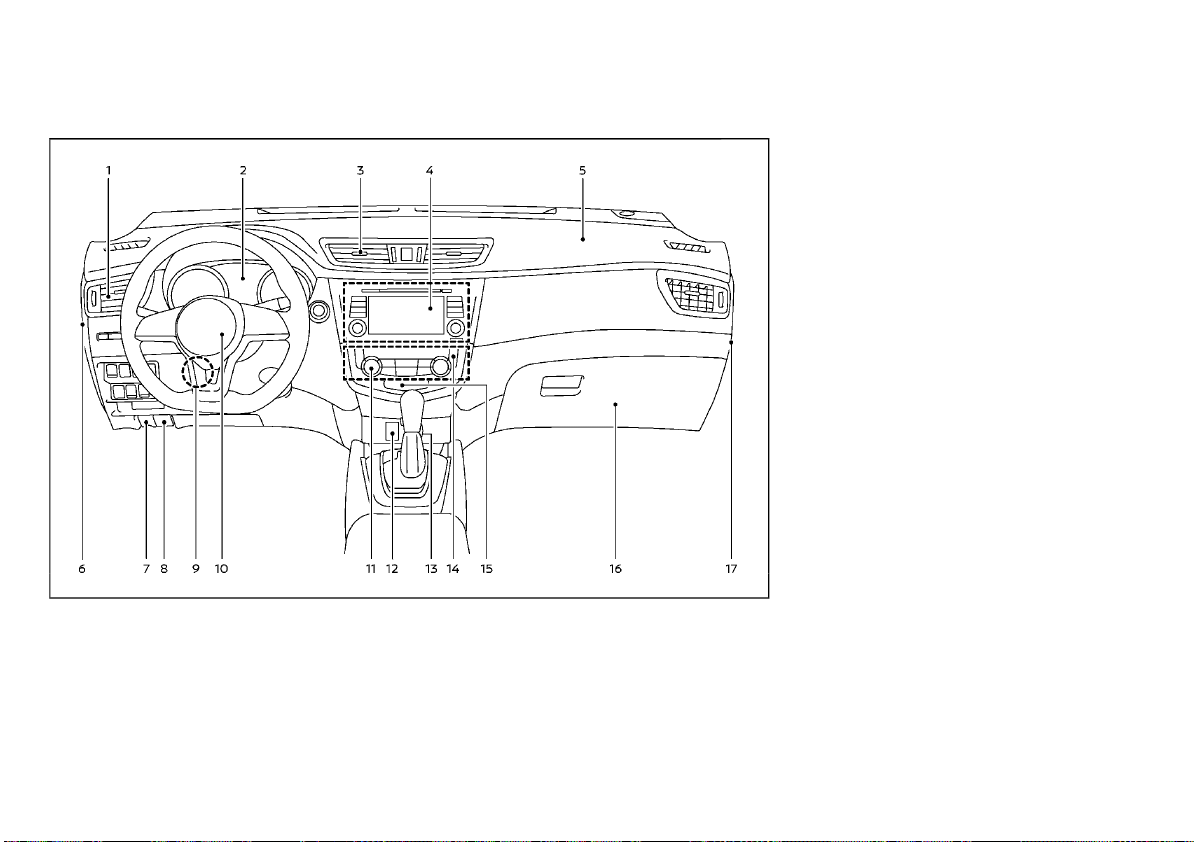
(77,1)
INSTRUMENT PANEL
LEFT-HAND DRIVE (LHD) MODEL
1. Side ventilator
2. Meters and gauges/Clock
3. Center ventilator
4. Audio system* or Navigation System*
— Center multi-function control panel*
— Rear view monitor*
—Intelligent Around View Monitor/
Around View Monitor*
— Bluetooth® Hands-Free Phone System
8. Hood release handle*
9. Steering wheel lock lever
10. Driver’s front-impact air bag/Horn
11. Heater/air conditioner control
12. Auxiliary input jack* and USB connection
port*
13. Power outlet* or Cigarette lighter*
14. Defogger switch
15. Front passenger air bag status light*
16. Glove box
17. Fuse box cover*
*: if equipped
WAA0061X
(without navigation)*
— Bluetooth® Hands-Free Phone System
(with navigation)*
— Voice Recognition System*
5. Passenger’s front-impact air bag
6. Fuse box cover
7. Fuel-filler lid release handle* or Hood
release handle*
Instruments and controls 2-7
Page 78
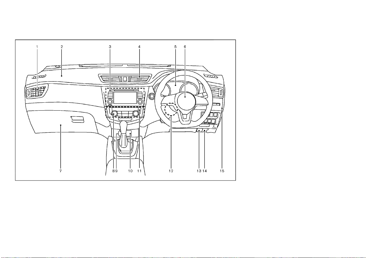
(78,1)
RIGHT-HAND DRIVE (RHD) MODEL
1. Side ventilator
2. Passenger’s front-impact air bag
3. Audio system* or Navigation System*
— Center multi-function control panel*
— Rear view monitor*
—Intelligent Around View Monitor/
Around View Monitor*
— Bluetooth® Hands-Free Phone System
(without navigation)*
8. Heater/air conditioner control
9. Power outlet* or Cigarette lighter* or
Auxiliary input jack* and USB connection
port*
10. Auxiliary input jack* and USB connection
port* or Power outlet* or Cigarette lighter*
11. Defogger switch
12. Steering wheel lock lever
13. Hood release handle
14. Fuel-filler lid release handle
15. Fuse box cover*
*: if equipped
JVC1028X
— Bluetooth® Hands-Free Phone System
(with navigation)*
— Voice Recognition System*
4. Center ventilator
5. Meters and gauges/Clock
6. Driver’s front-impact air bag/Horn
7. Glove box
— Fuse box
2-8 Instruments and controls
Page 79
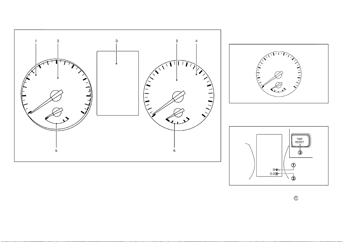
(79,1)
METERS AND GAUGES
1. Tachometer
2. Warning/indicator lights
3. Vehicle information display
— Odometer/twin trip odometer
4. Speedometer
5. Engine coolant temperature gauge
6. Fuel gauge
SPEEDOMETER AND ODOMETER
Speedometer
JVI1006X
The speedometer indicates the vehicle speed
(km/h or MPH).
Distance to empty (dte — km or mile)/Odometer
JVC0581X
JVI1603X
Distance to empty (dte — km or mile):
The distance to empty (dte) provides you
with an estimation of the distance that can be
driven before refueling. The dte is constantly
being calculated, based on the amount of fuel
in the fuel tank and the actual fuel consumption.
Instruments and controls 2-9
Page 80
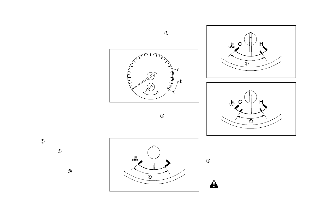
(80,1)
The display is updated every 30 seconds.
The dte mode includes a low range warning
feature. If the fuel level is low, the warning is
displayed on the screen.
When the fuel level drops even lower, the dte
display will change to “———”.
. If the amount of fuel added is small, the
display just before the ignition switch is
placed in the “OFF” position may continue
to be displayed.
. When driving uphill or rounding curves, the
fuel in the tank shifts, which may momentarily change the display.
Odometer/Twin trip odometer:
After the ignition switch is placed in the “OFF”
or “LOCK” position from “ON” position, the
odometer/twin trip odometer stays on for 30
seconds. With the ignition switch in the “OFF”
position, when you open any door then close all
doors, the odometer/twin trip odometer stays
on for 30 seconds.
The odometer/twin trip odometer is displayed
in the vehicle information display when the
ignition switch is in the “ON” position.
The odometer
displays the total distance the
vehicle has been driven.
The twin trip odometer
displays the distance
of individual trips.
Changing odometer/twin trip odometer display:
Push the TRIP RESET switch
(located on the
instrument panel) to change the display as
follows:
ODO ? TRIP A ? TRIP B ? ODO
Resetting twin trip odometer:
Push the TRIP RESET switch
for more than 1
second to reset the trip odometer to zero.
TACHOMETER
JVI0951X
The tachometer indicates the engine speed in
revolutions per minute (rpm). Do not rev the
engine into the red zone
.
The red zone varies with models.
ENGINE COOLANT TEMPERATURE
GAUGE
Type A
JVI0999X
Type B
The engine coolant temperature gauge indi-
Type C
JVI0820X
JVI0796X
cates the engine coolant temperature.
The engine coolant temperature is normal
when the gauge needle points within the zone
shown in the illustration.
The engine coolant temperature will vary with
the outside air temperature and driving conditions.
CAUTION:
. If the gauge indicates the engine coolant
temperature is near the hot (H) end of the
normal range, reduce vehicle speed to
2-10 Instruments and controls
Page 81
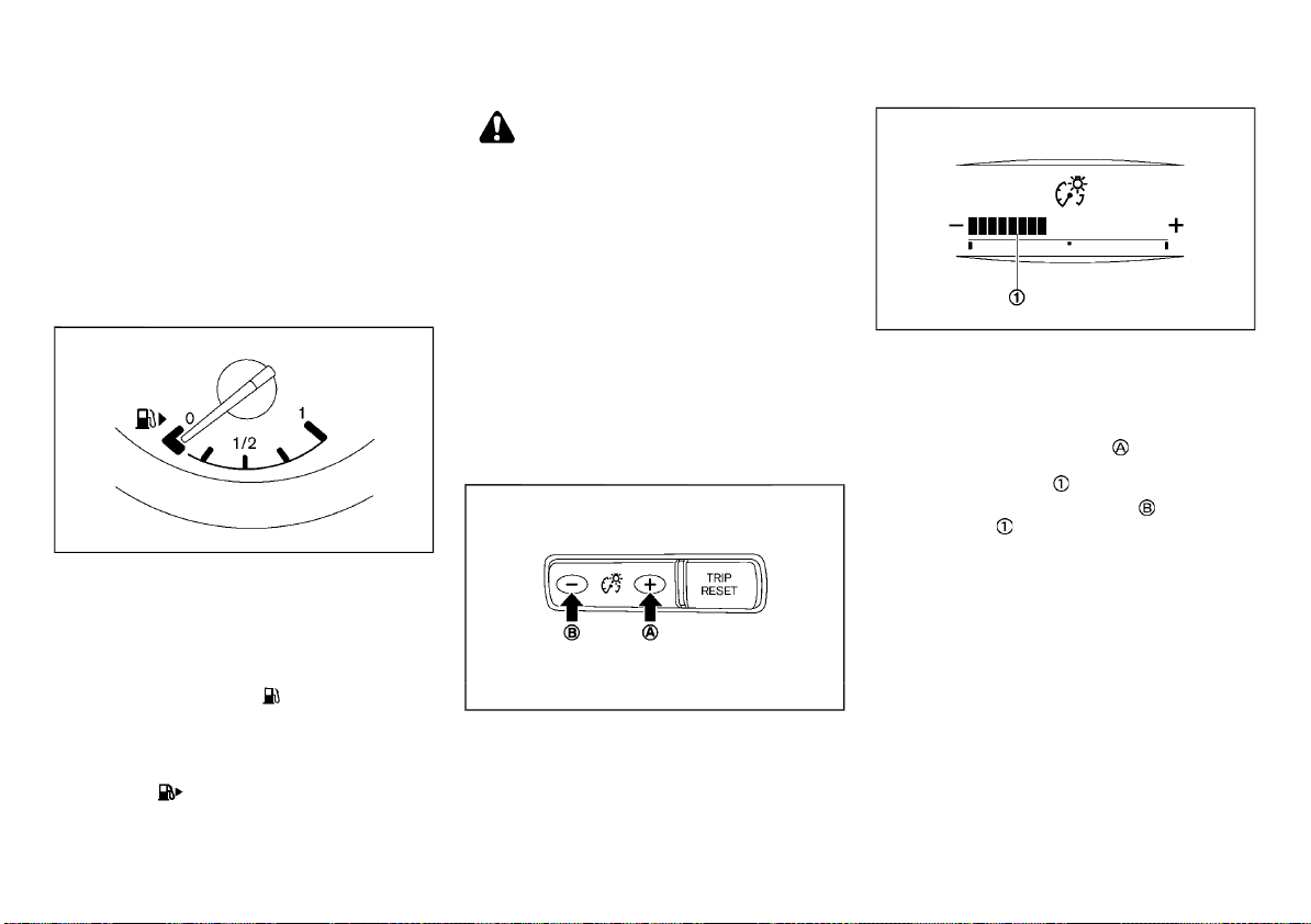
(81,1)
decrease the temperature.
. If the gauge is over the normal range,
stop the vehicle as soon as safely possible and let the engine idle.
. If the engine is overheated, continued
operation of the vehicle may seriously
damage the engine. (See “If your vehicle
overheats” (P.6-11) for immediate action
required.)
FUEL GAUGE
JVI0640X
The fuel gauge indicates the approximate fuel
level in the tank when the ignition switch is in
the “ON” position.
The gauge may move slightly during braking,
turning, accelerating, or going up and down
hills due to movement of fuel in the tank.
The low fuel warning
vehicle information display when the fuel level
in the tank is getting low. Refuel as soon as it is
convenient, preferably before the gauge reads
0 (empty).
The arrow,
located on the right side of the vehicle.
, indicates the fuel-filler lid is
appears on the
CAUTION:
Refuel before the gauge reads the empty (0)
position.
There is a small reserve of fuel in the tank when
the fuel gauge reads the empty (0) position.
Malfunction Indicator Light (MIL)
For Korea:
If the Malfunction Indicator Light (MIL) illuminates while the engine is running, it may
indicate that the fuel-filler cap is loose or
missing, or that the fuel level is low. Make sure
that the fuel-filler cap is installed and closed
tightly, and that a sufficient amount of fuel
remains in the fuel tank. (See “Malfunction
Indicator Light (MIL)” (P.2-19).)
INSTRUMENT BRIGHTNESS CONTROL
JVI0644X
JVI0661M
The instrument brightness control switch can
be operated when the ignition switch is in the
“ON” position. When the switch is operated, the
vehicle information display switches to the
brightness adjustment mode.
Push the + side of the switch
meter panel lights and instrument panel lights
(if equipped). The bar
Push the - side of the switch
lights. The bar
The vehicle information display returns to the
normal display when the instrument brightness
control switch is not operated for more than 5
seconds.
moves to the − side.
to brighten the
moves to the + side.
to dim the
CONTINUOUSLY VARIABLE TRANSMISSION (CVT)/DUAL CLUTCH TRANSMISSION (DCT) POSITION INDICATOR (if
equipped)
The Continuously Variable Transmission (CVT)/
Dual Clutch Transmission (DCT) position indicator indicates the shift lever position when the
ignition switch is in the “ON” position.
Instruments and controls 2-11
Page 82
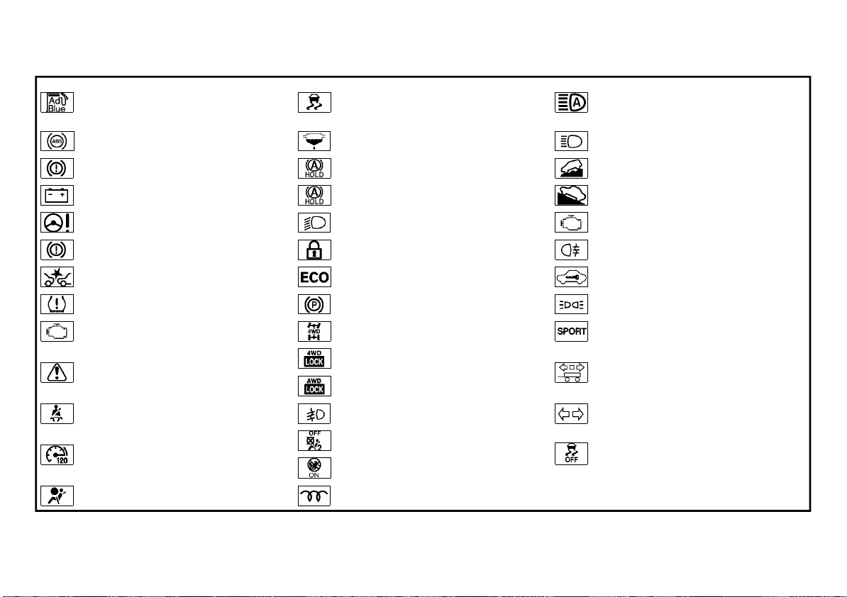
(82,1)
WARNING LIGHTS, INDICATOR
LIGHTS AND AUDIBLE REMINDERS
AdBlue® warning light*
Anti-lock Braking System (ABS) warning light
Brake warning light (red)
Charge warning light
Electric power steering warning light Dipped beam indicator light*
Electronic parking brake system
warning light (yellow)*
Intelligent Emergency Braking system
warning light*
Low tire pressure warning light*
Malfunction Warning Light (MWL) (red)*
Vehicle Dynamic Control (VDC) warning light (except for Europe)/Electronic
Stability Program (ESP) warning light
(for Europe)
Water-in-fuel-filter warning light*
Automatic brake hold indicator (white)
*
Automatic brake hold indicator
(green)*
Door lock indicator light*
ECO mode system indicator light*
Electronic parking brake indicator
light*
Four-Wheel Drive (4WD) AUTO indicator light (4WD model)
High beam assist indicator light*
High beam indicator light
Hill descent control system on indicator light*
Hill Start Assist system on indicator
light*
Malfunction Indicator Light (MIL)
Rear fog light indicator light*
Security indicator light
Small light indicator light
SPORT mode indicator light*
Master warning light
Seat belt warning light Front fog lights indicator light*
Speed [120 km/h (75 MPH)] warning
light*
Supplemental Restraint System (SRS)
air bag warning light
2-12 Instruments and controls
Four-Wheel Drive (4WD)/All-Wheel
Drive (AWD) LOCK indicator light*
Front passenger air bag status light*
Glow plug indicator light*
Trailer direction indicator light*
Turn signals/hazard indicator lights
Vehicle Dynamic Control (VDC) off
indicator light (except for Europe)/
Electronic Stability Program (ESP) off
indicator light (for Europe)
*: if equipped
Page 83
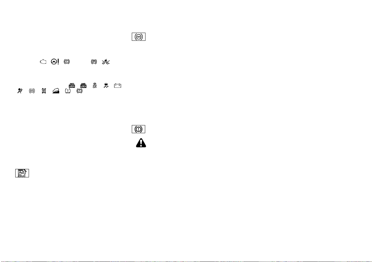
(83,1)
CHECKING LIGHTS
With all doors closed, apply the parking brake,
fasten the seat belts and place the ignition
switch in the “ON” position without starting the
engine. The following lights (if equipped) will
come on:
*1: models not equipped with electronic parking
brake system
The following lights (if equipped) will come on
briefly and then go off:
, , , , , (red)*2.
*2: models equipped with electronic parking
brake system
If any light does not come on or operates in a
way other than described, it may indicate a
burned-out bulb and/or a system malfunction.
Have the system checked, and if necessary
repaired, by a NISSAN dealer promptly.
Some indicators and warnings are also displayed on the vehicle information display
between the speedometer and tachometer.
(See “Vehicle information display” (P.2-21).)
, , (red)*1, , .
, , , , ,
WARNING LIGHTS
AdBlue® warning light (if equipped
for diesel engine model)
The AdBlue® warning light will illuminate if the
level of AdBlue® fluid in the AdBlue® tank is
getting low, or if there is a malfunction in the
AdBlue® system. See “AdBlue® Selective Catalytic Reduction (SCR) system (if equipped for
diesel engine model)” (P.5-5).
Anti-lock Braking System (ABS)
warning light
When the ignition switch is in the “ON” position,
the Anti-lock Braking System (ABS) warning
light illuminates and then turns off. This indicates the ABS is operational.
If the ABS warning light illuminates while the
engine is running, or while driving, it may
indicate the ABS is not functioning properly.
Have the system checked by a NISSAN dealer
promptly.
If an ABS malfunction occurs, the anti-lock
function is turned off. The brake system then
operates normally, but without anti-lock assistance. (See “Brake system” (P.5-103).)
Brake warning light (red)
WARNING:
. If the brake fluid level is below the
minimum mark on the brake fluid reservoir, do not drive the vehicle until the
brake system has been checked by a
NISSAN dealer.
. Even if you judge it to be safe, have your
vehicle towed because driving it could be
dangerous.
. Depressing the brake pedal without the
engine running and/or with a low brake
fluid level could increase the stopping
distance and require greater pedal travel
distance and effort.
The brake warning light indicates the parking
brake system operation (models not equipped
with electronic parking brake system), a low
brake fluid level of the brake system and an
Anti-lock Braking System (ABS) malfunction.
Parking brake warning indicator (models not
equipped with electronic parking brake system):
When the ignition switch is placed in the “ON”
position, the brake warning light illuminates.
When the engine is started and the parking
brake is released, the brake warning light turns
off.
If the parking brake is not fully released, the
brake warning light remains on. Be sure that
the brake warning light has turned off before
driving. (See “Parking brake” (P.3-40).)
Low brake fluid warning indicator:
When the ignition switch is placed in the “ON”
position, the brake warning light illuminates,
and then turns off (models equipped with
electronic parking brake system).
If the brake warning light illuminates while the
engine is running, or while driving, and the
parking brake is released, it may indicate the
brake fluid level is low.
When the brake warning light illuminates while
driving, stop the vehicle safely as soon as
possible. Stop the engine and check the brake
fluid level. If the brake fluid level is at the
minimum mark, add brake fluid as necessary.
(See “Brake fluid” (P.8-21).)
If the brake fluid level is sufficient, have the
brake system checked by a NISSAN dealer
promptly.
Anti-lock Braking System (ABS) warning indicator:
When the parking brake is released and the
brake fluid level is sufficient, if both the brake
warning light and the Anti-lock Braking System
(ABS) warning light illuminate, it may indicate
Instruments and controls 2-13
Page 84
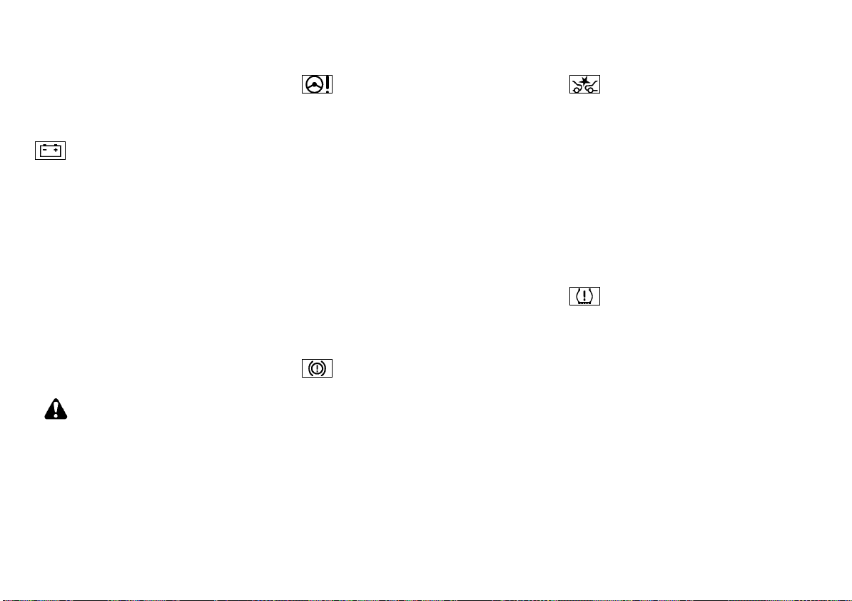
(84,1)
the ABS is not functioning properly. Have the
brake system checked, and if necessary repaired, by a NISSAN dealer promptly. (See “Antilock Braking System (ABS) warning light” (P.2-
13).)
Charge warning light
When the ignition switch is in the “ON” position,
the charge warning light illuminates, and then
turns off. This indicates the charging system is
operational.
If the charge warning light illuminates while the
engine is running, or while driving, it may
indicate the charging system is not functioning
properly and may need servicing.
When the charge warning light illuminates
while driving, stop the vehicle safely as soon
as possible. Stop the engine and check the
alternator belt. If the alternator belt is loose,
broken or missing, the charging system needs
repair. (See “Drive belt” (P.8-18).)
If the alternator belt appears to be functioning
correctly but the charge warning light remains
illuminated, have the charging system checked
by a NISSAN dealer promptly.
CAUTION:
Do not continue driving if the alternator belt
is loose, broken or missing.
Electric power steering warning light
When the ignition switch is in the “ON” position,
the electric power steering warning light illuminates. After starting the engine, the electric
power steering warning light turns off. This
indicates the electric power steering is operational.
If the electric power steering warning light
illuminates while the engine is running, it may
indicate the electric power steering is not
functioning properly and may need servicing.
Have the electric power steering checked by a
NISSAN dealer.
When the electric power steering warning light
illuminates with the engine running, the power
assist to the steering will cease operation but
you will still have control of the vehicle. At this
time, greater steering efforts are required to
operate the steering wheel, especially in sharp
turns and at low speeds.
(See “Electric power steering” (P.5-102).)
Electronic parking brake system
warning light (yellow) (if equipped)
The electronic parking brake system warning
light functions for the electronic parking brake
system. If the warning light illuminates at any
time, it may indicate that the electronic parking
brake system is not functioning properly. Have
the brake system checked, and if necessary
repaired, by a NISSAN dealer promptly.
Intelligent Emergency Braking
system warning light (if equipped)
When the ignition switch is in the “ON” position,
the Intelligent Emergency Braking system
warning light illuminates. After starting the
engine, the warning light turns off.
This light illuminates when the Intelligent
Emergency Braking system is set to OFF on
the vehicle information display.
If the light illuminates when the Intelligent
Emergency Braking system is ON, it may
indicate that the system is unavailable. See
“Intelligent Emergency Braking” (P.5-78) or “Intelligent Emergency Braking with pedestrian
detection system” (P.5-83).
Low tire pressure warning light (if
equipped)
When the ignition switch is in the “ON” position,
the low tire pressure warning light illuminates
and then turns off. This indicates that the low
tire pressure warning system is operational.
This light illuminates if there is low tire pressure
or a tire pressure warning system malfunction.
The Tire Pressure Monitoring System (TPMS)
monitors the tire pressure of all tires except the
spare.
Low tire pressure warning:
If the vehicle is being driven with low tire
pressure, the low tire pressure warning light
will illuminate.
When the low tire pressure warning light
illuminates, you should stop and adjust the tire
pressure to the recommended COLD tire pressure shown on the tire placard. Use a tire
pressure gauge to check the tire pressure. The
2-14 Instruments and controls
Page 85
(85,1)
low tire pressure warning light may not automatically turn off when the tire pressure is
adjusted. After the tire is inflated to the
recommended pressure, reset the tire pressures registered in your vehicle (model with
TPMS reset function) and then drive the vehicle
at speeds above 25 km/h (16 MPH). These
operations are required to activate the TPMS
and turn off the low tire pressure warning light.
Model with TPMS reset function:
TPMS resetting must be also performed after a
tire or a wheel is replaced, or the tires are
rotated.
Depending on a change in the outside temperature, the low tire pressure warning light
may illuminate even if the tire pressure has
been adjusted properly. Adjust the tire pressure
to the recommended COLD tire pressure again
when the tires are cold, and reset the TPMS.
If the low tire pressure warning light still
continues to illuminate after the resetting
operation, it may indicate that the TPMS is
not functioning properly. Have the system
checked by a NISSAN dealer.
For additional information, see “Tire Pressure
Monitoring System (TPMS)” (P.5-9).
TPMS malfunction:
If the TPMS is not functioning properly, the low
tire pressure warning light will flash for approximately 1 minute when the ignition switch
is placed in the “ON” position. The light will
remain on after the 1 minute. Have the system
checked by a NISSAN dealer.
For additional information, see “Tire Pressure
Monitoring System (TPMS)” (P.5-9).
WARNING:
. If the light does not illuminate with the
ignition switch placed in the “ON” position, have the vehicle checked by a
NISSAN dealer as soon as possible.
. If the light illuminates while driving, avoid
sudden steering maneuvers or abrupt
braking, reduce vehicle speed, pull off
the road to a safe location and stop the
vehicle as soon as possible. Driving with
under-inflated tires may permanently
damage the tires and increase the likelihood of tire failure. Serious vehicle
damage could occur and may lead to an
accident and could result in serious
personal injury. Check the tire pressure
for all four tires. Adjust the tire pressure
to the recommended COLD tire pressure
shown on the tire placard to turn the low
tire pressure warning light off. If the light
still illuminates while driving after adjusting the tire pressure, a tire may be flat or
the TPMS may be malfunctioning. If you
have a flat tire, replace it with a spare tire
as soon as possible. If no tire is flat and all
tires are properly inflated, have the vehicle checked by a NISSAN dealer.
. After adjusting the tire pressure, be sure
to reset the TPMS. Otherwise, the TPMS
will not warn of low tire pressure (model
with TPMS reset function).
. Since the spare tire is not equipped with
the TPMS, when a spare tire is mounted
or a wheel is replaced, the TPMS will not
function and the low tire pressure warning light will flash for approximately 1
minute. The light will remain on after the
1 minute. Contact your NISSAN dealer as
soon as possible for tire replacement
and/or system resetting.
. Replacing tires with those not originally
specified by NISSAN could affect the
proper operation of the TPMS.
CAUTION:
. The TPMS is not a substitute for the
regular tire pressure check. Be sure to
check the tire pressure regularly.
. If the vehicle is being driven at speeds of
less than 25 km/h (16 MPH), the TPMS
may not operate correctly.
. Be sure to install the specified size of tires
to all four wheels correctly.
Malfunction Warning Light (MWL)
(red) (if equipped)
When the ignition switch is placed in the “ON”
position, the Malfunction Warning Light (MWL)
illuminates in red. This means that the system
is operational. After starting the engine, the
MWL turns off.
For the orange Malfunction Indicator Light
(MIL), see “Malfunction Indicator Light (MIL)”
(P.2-19) for details.
If the MWL (red) illuminates continuously while
the engine is running, it may indicate an engine
control system malfunction. Have your vehicle
inspected by a NISSAN dealer. You do not need
to have your vehicle towed to the dealer.
CAUTION:
Continuing vehicle operation without proper
servicing of the engine control system could
lead to poor driveability, reduced fuel economy, and damage to the engine control
Instruments and controls 2-15
Page 86
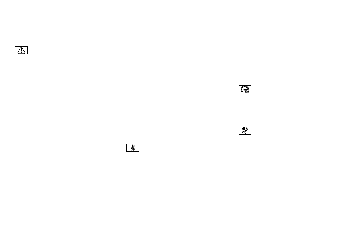
(86,1)
system, which may affect the vehicle’s warranty coverage.
Master warning light
When the ignition switch is in the “ON” position,
the master warning light illuminates if any of
the following are displayed on the vehicle
information display.
. Steering lock release malfunction indicator
(if equipped)
. No Key detected warning (if equipped)
. Key ID incorrect warning (if equipped)
. Shift to Park warning (Continuously Vari-
able Transmission (CVT)/Dual Clutch Transmission (DCT) models)
. Door/back door open warning
. Low fuel warning
. Release parking brake warning
. Engine start operation indicator (for Con-
tinuously Variable Transmission (CVT)/Dual
Clutch Transmission (DCT) models)
. Key System Fault warning (if equipped)
. Low Tyre Pressure warning (if equipped)
. TPMS system fault (if equipped)
. CVT System Fault warning (for Continu-
ously Variable Transmission (CVT) models)
. DCT System Fault warning (for Dual Clutch
Transmission (DCT) models)
. Low oil pressure Stop vehicle warning (if
equipped)
. 4WD system fault/AWD Error warning (if
equipped)
. 4WD/AWD High Temp. Stop vehicle warning
(if equipped)
. Tyre size incorrect warning (if equipped)
2-16 Instruments and controls
. Key battery low warning (if equipped)
. Battery Voltage Low Charge Battery warn-
ing
. Headlight system fault warning (if
equipped)
. Chassis control system fault warning
. Second row seat belt warning (if equipped)
. Adaptive Front lighting System (AFS) warn-
ing (if equipped)
. Oil level sensor warning (if equipped)
. AdBlue® warning (if equipped for diesel
engine model)
. Parking Sensor System Fault warning (if
equipped)
. System fault (if equipped)
. Press brake pedal warning (for electronic
parking brake equipped models)
. Loose fuel cap warning (if equipped)
. Other warning
See “Vehicle information display” (P.2-21).
Seat belt warning light
Type A:
The light illuminates whenever the ignition
switch is placed in the “ON” or “START” position,
and will remain illuminated until the driver’s
seat belt is fastened. At the same time, the
chime (if equipped) will sound for about 6
seconds unless the driver’s seat belt is securely
fastened.
Type B:
When the ignition switch is in the “ON” position,
the seat belt warning light on the meter
illuminates. The light will continue to illuminate
until the driver’s and/or front passenger’s (if
equipped) seat belts are fastened. (See “Seat
belts” (P.1-10).)
When the vehicle speed exceeds 15 km/h (10
MPH), the light will blink and the chime will
sound unless the driver’s and/or front passenger’s (if equipped) seat belts are securely
fastened. The chime will continue to sound for
about 95 seconds until the seat belt is fastened.
(See “Seat belts” (P.1-10).)
For second row seats, see “Vehicle information
display warnings and indicators” (P.2-30) (if
equipped).
Speed [120 km/h (75 MPH)] warn-
ing light (if equipped)
This light blinks when the vehicle speed goes
over approximately 120 km/h (75 MPH). Be sure
to observe the speed limit in the area where
you are driving.
Supplemental Restraint System
(SRS) air bag warning light
When the ignition switch is in the “ON” position,
the Supplemental Restraint System (SRS) air
bag warning light illuminates for about 7
seconds and then turns off. This indicates the
SRS air bag system is operational.
If any of the following conditions occur, the SRS
air bag system and/or pre-tensioner seat belt
need servicing. Have the system checked, and if
necessary repaired, by a NISSAN dealer
promptly.
. The SRS air bag warning light remains
illuminated after about 7 seconds.
. The SRS air bag warning light flashes
intermittently.
. The SRS air bag warning light does not
come on at all.
Unless checked and repaired, the SRS air bag
Page 87
(87,1)
system and/or pre-tensioner seat belt may not
function properly. (See “Supplemental Restraint
System (SRS)” (P.1-32).)
Vehicle Dynamic Control (VDC) warning
light (except for Europe)/Electronic Stability
Program (ESP) warning light (for Europe)
When the ignition switch is in the “ON” position,
the Vehicle Dynamic Control (VDC)/Electronic
Stability Program (ESP) warning light illuminates and then turns off.
The warning light blinks when the VDC/ESP
system is operating.
When the warning light blinks while driving, the
driving condition is slippery and the vehicle’s
traction limit is about to be exceeded.
If the VDC/ESP warning light illuminates while
the engine is running or while driving, it may
indicate that the VDC/ESP system is not
functioning properly and may need servicing.
Have the system checked, and if necessary
repaired, by a NISSAN dealer promptly. If a
malfunction occurs, the VDC/ESP function is
turned off, but the vehicle is still drivable. (See
“Vehicle Dynamic Control (VDC)/Electronic Stability Program (ESP) system” (P.5-35).)
Water-in-fuel-filter warning light
(if equipped for diesel engine model)
If the water-in-fuel-filter warning light illuminates while the engine is running, contact a
NISSAN dealer as soon as possible.
CAUTION:
Continuing vehicle operation without properly draining could cause serious damage to
the engine.
INDICATOR LIGHTS
Automatic brake hold indicator
(white) (if equipped)
The automatic brake hold indicator (white)
illuminates when the automatic brake hold
system become standby. (See “Automatic brake
hold” (P.3-42).)
Automatic brake hold indicator
(green) (if equipped)
The automatic brake hold indicator (green)
illuminates while the automatic brake hold
system is operating. (See “Automatic brake
hold” (P.3-42).)
Dipped beam indicator light (if equipped)
The dipped beam indicator light illuminates
when the headlight low beam is on. (See
“Headlight and turn signal switch” (P.2-43).)
Door lock indicator light (if equipped)
The door lock indicator light, located on the
instrument panel, illuminates when all the
doors are locked.
. With the ignition switch in the “ON” position,
the door lock indicator light will illuminate
and stay on when the doors are locked
using the power door lock switch.
. With the ignition switch in the “OFF” or
“LOCK” position, the door lock indicator
light will operate as follows:
—When the doors are locked with the
power door lock switch, the door lock
indicator light will illuminate for 30
minutes.
— When the doors are locked by pushing
the “LOCK” button (on the remote controller or Intelligent Key) or the request
switch (Intelligent Key system equipped
models), the door lock indicator light will
illuminate for 1 minute.
The door lock indicator light turns off when any
door is unlocked.
For locking or unlocking doors, see “Doors” (P.3-
5).
ECO mode system indicator light
(if equipped)
The ECO mode indicator light illuminates when
the ECO mode system is turned on.
(See “ECO mode system” (P.5-91).)
Electronic parking brake indicator
light (if equipped)
The electronic parking brake indicator light
indicates that the electronic parking brake
system is operating.
If the parking brake is not fully released, the
electronic parking brake indicator light remains
on. Be sure that the electronic parking brake
indicator light has turned off before driving.
(See “Parking brake” (P.3-40).)
If the electronic parking brake indicator light
illuminates or flashes while the electronic
parking brake system warning light
low) illuminates, it may indicate that the
electronic parking brake system is not functioning properly. Have the system checked, and
if necessary repaired, by a NISSAN dealer
promptly.
Instruments and controls 2-17
(yel-
Page 88
(88,1)
Four-Wheel Drive (4WD) AUTO
indicator light (4WD model)
When the ignition switch is in the “ON” position,
the Four-Wheel Drive (4WD) AUTO indicator
light illuminates and then turns off.
When selecting 4WD AUTO mode while the
engine is running, the 4WD AUTO indicator light
illuminates. (See “Intelligent 4x4 (if equipped
except for Korea)” (P.5-28).)
/ Four-Wheel Drive (4WD)/All-Wheel
Drive (AWD) LOCK indicator light (if equipped)
When the ignition switch is in the “ON” position,
the Four-Wheel Drive (4WD)/All-Wheel Drive
(AWD) LOCK indicator light illuminates and then
turns off.
For Korea: When selecting AWD LOCK mode
while the engine is running, the AWD LOCK
indicator light illuminates. (See “Intelligent 4x4
(if equipped for Korea)” (P.5-33).)
Except for Korea: When selecting 4WD LOCK
mode while the engine is running, the 4WD
LOCK indicator light illuminates simultaneously
with the 4WD AUTO indicator light illuminating.
“Intelligent 4x4 (if equipped except for Korea)”
(P.5-28).)
CAUTION:
Do not drive on dry hard surface roads in the
LOCK mode.
Front fog lights indicator light (if equipped)
The front fog lights indicator light illuminates
when the front fog lights are on. (See “Fog light
switch” (P.2-55).)
/ Front passenger air bag
status light (if equipped)
Models with Advanced Air Bag System:
The front passenger air bag status light ( )
located on the instrument panel will illuminate
and the front passenger air bag will be OFF
depending on how the front passenger seat is
being used.
For front passenger air bag status light operation, see “Supplemental front-impact air bag
system (with Advanced Air Bag System)” (P.1-
39).
Models without Advanced Air Bag System:
The front passenger air bag status light ( )
located on the instrument panel will illuminate
when the front passenger air bag is turned off
with the front passenger air bag switch. When
the front passenger air bag is turned on, the
front passenger air bag status light (
illuminate.
For more details, see “Supplemental frontimpact air bag system (without Advanced Air
Bag System)” (P.1-43).
) will
Glow plug indicator light (if
equipped for diesel engine model)
When the ignition switch is in the “ON” position,
the glow plug indicator light illuminates and
turns off after the glow plugs have warmed up.
If the glow plugs have already warmed up, the
glow plug indicator flashes briefly and then
turns off.
High beam assist indicator light (if
equipped)
The indicator light illuminates when the headlights come on while the headlight switch is in
the “AUTO” position with the high beam selected. This indicates that the high beam assist
system is operational. (See “Headlight and turn
signal switch” (P.2-43).)
High beam indicator light
The high beam indicator light illuminates when
the headlight high beam is on. The indicator
turns off when the low beam is selected. (See
“Headlight and turn signal switch” (P.2-43).)
Hill descent control system on
indicator light (if equipped)
When the ignition switch is placed in the “ON”
position the hill descent control system on
indicator light illuminates briefly and then turns
off. This indicates that the hill descent control
system is operational.
The light illuminates when the hill descent
control system is activated.
If the hill descent control switch is on and the
indicator light blinks, the system is not en-
2-18 Instruments and controls
Page 89
(89,1)
gaged.
If the indicator light does not illuminate or blink
when the hill descent control switch is on, the
system may not be functioning properly. Have
the system checked by a NISSAN dealer.
For additional information, see “Hill descent
control system” (P.5-39).
Hill Start Assist system on indica-
tor light (if equipped)
The light illuminates when the conditions of the
hill start assist system are satisfied when the
vehicle is stopped on a hill.
Then, the light blinks when the brake pedal is
released, which indicates that the hill start
assist system is activated.
For additional information, see “Hill Start Assist
system” (P.5-39).
Malfunction Indicator Light (MIL)
CAUTION:
. Continuing vehicle operation without
proper servicing of the engine control
system and/or Continuously Variable
Transmission (CVT)/Dual Clutch Transmission (DCT) system could lead to poor
driveability, reduced fuel economy, and
damage to the engine control system
and/or CVT/DCT system, which may affect the vehicle’s warranty coverage.
. Incorrect setting of the engine control
system may lead to non-compliance of
local and national emission laws and
regulations.
When the ignition switch is in the “ON” position,
the Malfunction Indicator Light (MIL) illuminates. After starting the engine, the MIL turns
off. This indicates that the engine control
system and/or CVT/DCT system is operational.
For Korea:
When the ignition switch is in the “ON” position,
sometimes the MIL may illuminate for 20
seconds and then blink for 10 seconds, without
the engine running. This is due to a function of
checking the engine control system, and it is
not a malfunction. After a few normal drives,
this function will not occur and the MIL stays
illuminated with the ignition switch in the “ON”
position.
If the MIL illuminates while the engine is
running, it may indicate that the fuel-filler cap
is loose or missing, or that the fuel level is low.
Check the fuel-filler cap if the LOOSE FUEL CAP
warning appears on the vehicle information
display. Make sure that the fuel-filler cap is
installed and closed tightly, and that a sufficient
amount of fuel remains in the fuel tank. After a
few driving trips, the MIL should turn off. If the
MIL continues to be illuminated, it may indicate
that the engine control system is not functioning properly and may need servicing. Have the
vehicle checked, and if necessary repaired, by a
NISSAN dealer promptly.
If the MIL blinks while the engine is running, it
may indicate a potential malfunction in the
emission control system. In this case, the
emission control system may not function
properly and may need servicing. Have the
system checked, and if necessary repaired, by a
NISSAN dealer promptly.
Except for Korea:
If the MIL illuminates while the engine is
running, it may indicate that the engine control
system is not functioning properly and may
need servicing. Have the vehicle checked, and if
necessary repaired, by a NISSAN dealer
promptly.
If the MIL blinks (if equipped) while the engine is
running, it may indicate a potential malfunction
in the emission control system. In this case, the
emission control system may not function
properly and may need servicing. Have the
system checked, and if necessary repaired, by a
NISSAN dealer promptly.
Precautions:
To reduce or avoid possible damage to the
engine control system when the MIL blinks:
. Avoid driving at speeds above 70 km/h (43
MPH).
. Avoid going up steep uphill grades.
. Avoid carrying or towing unnecessary
loads.
For MR20DD engine model:
When the ignition switch is in the “ON” position,
sometimes the MIL may illuminate for 20
seconds and then blink for 10 seconds, without
the engine running. This is due to a function of
checking the engine control system, and it is
not a malfunction. After a few normal drives,
this function will not occur and the MIL stays
illuminated with the ignition switch in the “ON”
position.
Instruments and controls 2-19
Page 90
(90,1)
Rear fog light indicator light (if equipped)
The rear fog light indicator light illuminates
when the rear fog light is on. (See “Fog light
switch” (P.2-55).)
Security indicator light
The security indicator light blinks when the
ignition switch is in the “LOCK”, “OFF” position.
This function indicates the security system
equipped on the vehicle is operational.
If the security system is malfunctioning, this
light will remain on while the ignition switch is
in the “ON” position. (See “Security indicator
light” (P.3-22) for additional information.)
Small light indicator light
The light illuminates when the headlight switch
is turned to the
position.
SPORT mode indicator light (if equipped)
The SPORT mode indicator light illuminates
when the SPORT mode is turned “ON”. (See
“Driving with Continuously Variable Transmission (CVT)/Driving with Dual Clutch Transmission (DCT)” (P.5-19) for the use of the SPORT
mode switch.)
Trailer direction indicator light (if
equipped)
The light will illuminate whenever an additional
electrical load is detected by the direction
indicator system.
For additional information, see “Trailer towing
(for Australia, New Zealand, South Africa, Ar-
2-20 Instruments and controls
gentina and Europe)” (P.5-98).
Turn signals/hazard indicator lights
The turn signals/hazard indicator lights blink
when the turn signal switch or hazard indicator
flasher switch is turned on. (See “Headlight and
turn signal switch” (P.2-43) or “Hazard indicator
flasher switch” (P.6-2).)
Vehicle Dynamic Control (VDC) off indicator light (except for Europe)/Electronic Stability Program (ESP) off indicator light (for Europe)
When the ignition switch is in the “ON” position,
the Vehicle Dynamic Control (VDC)/Electronic
Stability Program (ESP) off indicator light illuminates and then turns off.
The VDC/ESP off indicator light illuminates
when the VDC/ESP off switch is pushed to the
“OFF” position.
When the VDC/ESP off switch is pushed to the
“OFF” position, the VDC/ESP system is turned
off.
For details, see “Vehicle Dynamic Control (VDC)/
Electronic Stability Program (ESP) system” (P.5-
35).
AUDIBLE REMINDERS
Brake pad wear warning
The disc brake pads have audible wear warnings. When a brake pad requires replacement, it
will make a high pitched scraping sound when
the vehicle is in motion. This scraping sound
will first occur only when the brake pedal is
depressed. After more wear of the brake pad,
the sound will always be heard even if the
brake pedal is not depressed. Have the brakes
checked as soon as possible if the wear
warning sound is heard.
Have the system checked, and if necessary
repaired, by a NISSAN dealer promptly. (See
“Brakes” (P.8-20).)
Door lock warning chime (if equipped)
When the chime sounds, be sure to check both
the vehicle and the Intelligent Key. (See “Troubleshooting guide” (P.3-17).)
Light reminder chime
The chime will sound if the driver’s side door is
opened while the headlight switch is in either
the
is in the “OFF” or “LOCK” position.
Be sure to turn the light switch to the “OFF” or
“AUTO” (if equipped) position when you leave
the vehicle.
or position and the ignition switch
Parking brake reminder chime
The chime will sound if the vehicle is driven at
more than 7 km/h (4 MPH) (models not
equipped with electronic parking brake) or 4
km/h (2 MPH) (models equipped with electronic
parking brake) with the parking brake applied.
Stop the vehicle and release the parking brake.
Stop/Start System or Idling Stop System reminder buzzer (if equipped)
The engine will shift to the normal stopped
state if any of the following operations is made
during Stop/Start System or Idling Stop System
activation, and the Stop/Start System or Idling
Stop System buzzer will sound if:
. The driver’s seat belt is unfastened and the
driver’s door is open (MT models).
. The vehicle engine hood is open.
Close the hood or the driver’s door, or fasten
the seat belt then restart the engine using the
Page 91
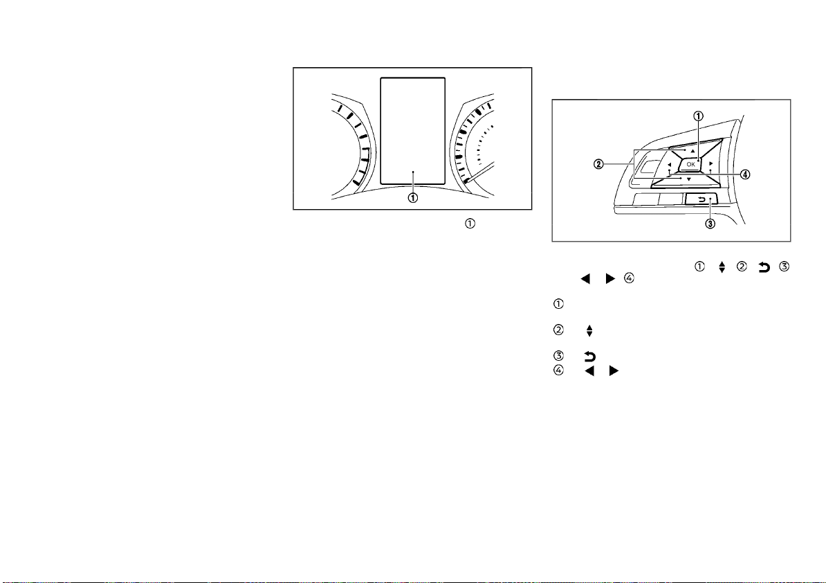
(91,1)
VEHICLE INFORMATION DISPLAY
ignition switch.
For more information, see “Stop/Start System
or Idling Stop System” (P.5-24).
JVI0641X
The vehicle information display is located
between the tachometer and the speedometer. It displays following items if the vehicle
is equipped with them:
. Vehicle settings
. Trip computer information
. Driver Assistance
. Speed limiter information
. Cruise control system information
. Intelligent Cruise Control (ICC) system in-
formation
. Intelligent Key operation information
. Audio information
. Navigation - turn by turn
. Indicators and warnings
. Tyre pressure information
. Chassis Control
. AdBlue® Selective Catalytic Reduction (SCR)
system information
. Other information
Please note that the information used in this
manual is written in UK English. There are a few
differences in the information for the UK and
U.S. English versions of the system.
For language settings, see “Language” (P.2-29).
HOW TO USE THE VEHICLE INFORMATION DISPLAY
JVI1566X
The vehicle information display can be changed using the buttons OK
and
steering wheel.
OK - change or select an item in the
vehicle information display
cle information display
to the next (i.e. trip, Fuel economy)
The buttons on the steering wheel mounted
controls are also used to control audio functions. For additional information, see “Steering
wheel mounted controls for audio” (P.4-72) or
the separate NissanConnect Owner’s Manual (if
equipped).
located on the left side of the
- navigate through the items in vehi-
- go back to the previous menu
- change from one display screen
, , ,
Instruments and controls 2-21
Page 92

(92,1)
STARTUP DISPLAY
When the ignition switch is placed in the “ON”
position, the screens that display in the vehicle
information display include:
. Trip computer
. Fuel economy
. Warnings
Warnings will only display if there are any
present, for more information on warnings
and indicators, see “Vehicle information display
warnings and indicators” (P.2-30).
To control what items display in the vehicle
information display, see “Settings” (P.2-22).
SETTINGS
The setting mode allows you to change the
information displayed in the vehicle information display:
. Driver Assistance
. Clock
. Display Settings
. Vehicle Settings
. Maintenance
. Alert
. Tyre Pressures (if equipped)
. Units (if equipped)
. Language (if equipped)
. Factory Reset
Driver Assistance
To change the status, warnings or turn on or
off any of the systems/warnings displayed in
the “Driver Assistance” menu, use the
button to select and the OK button to
change a menu item:
. Driving Aids (if equipped)
. Driver Attention (if equipped)
. Traffic Sign (if equipped)
. Parking Aids (if equipped)
. Chassis Control
Driving Aids (if equipped) :
To change the status, warnings or turn on or
off any of the systems/warnings displayed in
the “Driving Aids” menu, use the
to select and the OK button to change a
menu item:
. Emergency Brake (if equipped)
Press the OK button
gent Emergency Braking system ON/OFF.
. Lane (if equipped)
— Warning
Press the OK button to turn the Lane
Departure Warning (LDW) system ON/
OFF.
— Assist (if equipped)
Press the OK button
Intelligent Lane Intervention system
ON/OFF.
. Blind Spot (if equipped)
Press the OK button
Spot Warning (BSW) system ON/OFF.
— Warning (if equipped)
Press the OK button
Spot Warning (BSW) system ON/OFF.
For additional information, see “Intelligent
Emergency Braking” (P.5-78), “Intelligent Emergency Braking with pedestrian detection system” (P.5-83), “Lane Departure Warning (LDW)”
(P.5-40) and “Blind Spot Warning (BSW)” (P.5-49).
to turn the Intelli-
to turn the Blind
button
to turn the
to turn the Blind
Driver Attention (if equipped) :
Intelligent Driver Alertness ON/OFF
Traffic Sign (if equipped) :
Traffic Sign ON/OFF
Parking Aids (if equipped) :
To change the status or turn on or off any of
the systems displayed in the “Parking Aids”
menu, use the
OK button
. Moving Object (if equipped)
Press the OK button
Object Detection (MOD) (if equipped) ON/
OFF.
. Cross Traffic (if equipped)
Press the OK button
Cross Traffic Alert (RCTA) (if equipped) ON/
OFF.
. Front Sensor (if equipped)
Press the OK button
. Rear Sensor (if equipped)
Press the OK button
. Display (if equipped)
Press the OK button
. Volume (if equipped)
— High/Med./Low
. Range (if equipped)
— Far/Mid./Near
For additional information, see “Rear Cross
Traffic Alert (RCTA)” (P.5-55), “Parking sensor
(sonar) system” (P.5-95) and “Intelligent Around
View Monitor/Around View Monitor” (P.4-11).
button to select and the
to change a menu item:
to turn the Moving
to turn the Rear
to turn ON/OFF.
to turn ON/OFF.
to turn ON/OFF.
2-22 Instruments and controls
Page 93

(93,1)
Chassis Control:
To change the status, warnings or turn on or
off any of the systems/warnings displayed in
the “Chassis Control” menu.
Use the
button
. Trace Control
— See “Intelligent Trace Control” (P.5-36) for
Press the OK button
. Engine Brake (if equipped)
— See “Intelligent Engine Brake (Continu-
Press the OK button
button to select and the OK
to change a menu item:
more information.
to turn ON/OFF.
ously Variable Transmission (CVT)/Dual
Clutch Transmission (DCT) models)” (P.5-
37) for more information.
to turn ON/OFF.
Clock
For models without navigation or audio
system:
Set Clock:
The clock setting can be changed using the
12H/24H:
The time setting can be selected from 12 hour
and 24 hour formats.
D.S.T (if equipped):
Turns the Daylight Savings Time on or off.
Time Zone (if equipped):
Select the applicable time zone from the list.
For models with NissanConnect navigation or
audio system:
and the OK buttons.
Automatic Time:
The adjustment settings can be selected from
“Auto”, “Manual” and “Time Zone”.
. Auto
. Manual
. Time Zone
12H/24H:
The time setting can be selected from 12 hour
and 24 hour formats.
D.S.T:
Turns the Daylight Savings Time on or off.
Time Zone:
Select the applicable time zone from the list.
Set Clock Manually:
The clock can be adjusted manually using the
and the OK buttons.
NOTE:
The clock is synchronized with the clock on
the center display. To set the clock on center
display, see the separate NissanConnect
Owner’s Manual.
For models with navigation or audio system
(except for NissanConnect):
To set the clock, see “Clock” (P.4-7), “Audio main
operation” (P.4-47), “Audio main operation” (P.4-
55) or “Audio main operation” (P.4-61) or the
separate Navigation System Owner’s Manual (if
equipped).
Display Settings
The display settings allows the customer to
choose from the various meter selections.
The display settings can be changed using the
and the OK buttons.
Contents Selection:
The items that display when the ignition switch
is placed in the “ON” position can be enabled/
disabled. To change the items that are displayed, use the
OK button
Body Colour:
The color of the vehicle that displays in the
vehicle information display when the ignition
switch is placed in the “ON” position can be
changed.
1. Use the
selected, and press OK button
2. Select the body color using the
and press OK button .
ECO Mode Settings (if equipped):
This setting allows the customer to change the
ECO mode system settings.
Use the
Settings” is selected, and press OK button
- ECO Glow
This setting allows the customer to enable/
disable the ambient ECO indicator in the
vehicle information display.
1. Use the
2. Press the OK button
ambient ECO in the vehicle information
display.
button to scroll and the
to select a menu item.
button until “Body Colour” is
.
button
button until “ECO Mode
.
button to select “ECO Glow”.
to turn ON/OFF the
Instruments and controls 2-23
Page 94

(94,1)
- Display
Type A
This setting allows the customer to enable/
Type B
WAC0086X
JVI0665X
disable the ECO pedal guide function.
1. Use the
2. Press the OK button
button to select “Display”.
to select “Pedal
Guide” or “Fuel econ.”.
For detailed information, see “ECO mode system” (P.5-91).
Stop/Start (if equipped):
To change the status, warnings or turn on or
off any of the systems/warnings displayed in
the “Stop/Start” menu, use the
select and the OK button
button to
to change a menu
item:
. Display
— Stop/Start display ON/OFF
. Trip CO2 Saving
The “Trip CO2 Saving” and engine stop time
mode shows the CO2 saving and engine
stop time since the last reset. The CO2
saving and engine stop time can be reset
by pushing the OK button
.
. Total CO2 saving
The “Total CO2 Saving” and engine stop
time mode shows:
— The estimated CO2 exhaust emissions
prevented.
— The engine stop time that the engine
has been stopped by the “Stop/Start or
Idling Stop” System.
NOTE:
The “Total CO2 saving” and engine stop
time values cannot be reset and show
accumulated “Stop/Start or Idling Stop”
System information since the vehicle was
built.
ECO Drive Report (if equipped):
- Display
This setting allows the customer to enable/
disable the ECO Drive Report in the vehicle
information display.
1. Use the
button to select “ECO Drive
Report”.
2. Press the OK button
to turn ON/OFF the
ECO management display in the vehicle
information display.
- View History
This setting allows the customer to reset the
past history of the fuel economy and the best
fuel economy.
Welcome Effect:
You can choose whether or not to display the
welcome screen when the ignition switch is
placed in the “ACC” or “ON” position. You can
also choose the following items to define how
the welcome screen looks:
. Dial and Pointer
. Display Effect
Select “Welcome Effects” using the
button
and press the OK button to select this
menu. Use the
button to navigate
between the menu options and press the OK
button
to turn each function ON/OFF.
Vehicle Settings
The vehicle settings allows the customer to
change settings for the following settings.
. Lighting
. Turn Indicator
. Unlocking
. Wipers
. Mirrors
. Remote Start (if equipped)
. Driving Position (if equipped)
The vehicle settings can be changed using the
, and the OK buttons.
2-24 Instruments and controls
Page 95

(95,1)
Lighting:
The “Lighting” menu has the following options:
. Welcome Light
The welcome lighting can be set to be ON
or OFF. From the “Lighting” menu, select
“Welcome Light”. Use the OK button
turn this feature ON or OFF.
. Int. Lamp Timer
The internal light timer can be set to be ON
or OFF. From the “Lighting” menu, select
“Int. Lamp Timer”. Use the OK button
turn this feature ON or OFF.
. Auto Lights (if equipped)
The sensitivity of the Auto Light or the
Intelligent Auto Headlight can be adjusted.
From the “Lighting” menu, select “Auto
Lights”. Use the
button
The following options are available:
— On Earliest
— On Earlier
— Standard
— On Later
. Headlight Off Delay (if equipped)
The duration of the automatic headlights
can be changed from 0 to 180 seconds.
From the “Lighting” menu, select “Headlight
Off delay”. Use the OK button
the duration.
Turn Indicator:
The “3 Flash On” overtaking feature can be set
to be ON or OFF. From the “Turn Indicator”
menu, select “3 Flash On”. Use the OK button
to turn this feature ON or OFF.
to select the required sensitivity.
button and the OK
to change
Unlocking (if equipped):
There are the following options in the “Unlocking” menu:
. I–Key Door Lock (if equipped)
to
to
When this item is turned on, the request
switch on the door is activated. From the
“Unlocking” menu, select “I-Key Door Lock”.
Use the OK
deactivate this function.
. Selective Unlock (if equipped)
When this item is turned on, and the door
handle request switch on the driver’s or
front passenger’s side door is pushed, only
the corresponding door is unlocked. All the
doors can be unlocked if the door handle
request switch is pushed again within 1
minute. When this item is turned to off, all
the doors will be unlocked when the door
handle request switch is pushed once.
From the “Unlocking” menu, select “Selective Unlock”. Use the OK button
activate or deactivate this function.
. Auto Door Unlock (if equipped)
This menu allows the user to customize the
auto door unlock options. The following
options are available:
— Ignition OFF
— Shift to Park
— Off
. Answer Bk. Horn (if equipped)
When the answer back horn is on the horn
will chirp and the hazard indicators will
flash once when locking the vehicle with
the Intelligent Key or remote keyless entry
function.
button to activate or
Wipers:
. Speed Dependent (if equipped)
The “Speed Dependent” feature can be
activated or deactivated. From the “Wipers”
menu, select “Speed Dependent”. Use the
OK button
. Auto Wipe (if equipped)
The “Auto Wipe” feature can be activated or
deactivated. From the “Wipers” menu, select
“Auto Wipe”. Use the OK button
this feature ON or OFF.
. Rain Sensor (if equipped)
The “Rain sensor” feature can be activated
or deactivated. From the “Wipers” menu,
select “Rain Sensor”. Use the OK button
to turn this feature ON or OFF.
. Reverse Link
The “Reverse Link” wiper feature can be set
to be ON or OFF. From the “Wipers” menu,
to
select “Reverse Link”. Use the OK button
to turn this feature ON or OFF.
. Drip Wipe
The “Drip Wipe” feature can be set to be ON
or OFF. From the “Wipers” menu, select “Drip
Wipe”. Use the OK button
feature ON or OFF.
Mirrors (if equipped):
. Auto Fold Off
When this item is turned on, the auto fold
feature for the outside rearview mirrors is
disabled. Use OK button
function.
. Unfold at Ignition
When this item is turned on, the outside
rearview mirrors automatically fold when
the ignition switch is placed in the “OFF”
position, and unfold when the ignition
switch is placed in the “ON” position. Use
to turn this feature ON or OFF.
to turn
to turn this
to select this
Instruments and controls 2-25
Page 96
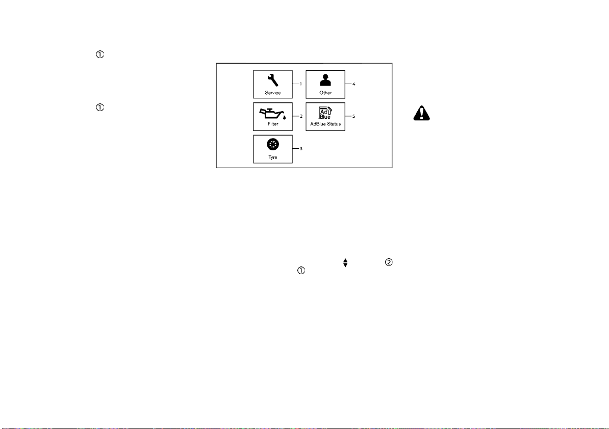
(96,1)
the OK button to select this function.
. Unfold at Unlock
When this item is turned on, the outside
rearview mirrors automatically fold when
the vehicle doors are locked, and unfold
when the vehicles doors are unlocked. Use
the OK button
Remote Start (if equipped):
The “Remote Start” feature allows user to turn
the remote engine start on or off. When turned
on, the engine can be started remotely. See
“Remote engine start” (P.3-20) for more information.
Driving Position (if equipped):
Displays the available driving position options.
. Exit Seat Slide
When this item is turned on, this feature will
move the driver’s seat backward for an
easy exit when the ignition is turned off and
the driver’s door is opened. After getting
into the vehicle and placing the ignition
switch in the ON position, the driver’s seat
will move to the previous set position. See
“Automatic drive positioner” (P.3-44) for
more information.
to select this function.
Maintenance
WAC0092X
1. Service
2. Filter (if equipped)
3. Tyre
4. Other
5. AdBlue Status (if equipped)
The maintenance mode allows you to set alerts
for the reminding of maintenance intervals. To
change an item:
Select “Maintenance” using the
and press OK button .
Service:
This indicator appears when the customer set
distance comes for changing the engine oil and
filter. You can set or reset the distance for
checking or replacing these items. For scheduled maintenance items and intervals, see a
separate maintenance booklet.
Filter (if equipped):
This indicator appears when the customer set
distance comes for changing the oil filter. You
can set or reset the distance for checking or
replacing these items. For scheduled maintenance items and intervals, see a separate
button
maintenance booklet.
Tyre:
This indicator appears when the customer set
distance comes for replacing tires. You can set
or reset the distance for replacing tires.
WARNING:
The tire replacement indicator is not a substitute for regular tire checks, including tire
pressure checks. See “Changing tires and
wheels” (P.8-43). Many factors including tire
inflation, alignment, driving habits and road
conditions affect tire wear and when tires
should be replaced. Setting the tire replacement indicator for a certain driving distance
does not mean your tires will last that long.
Use the tire replacement indicator as a guide
only and always perform regular tire checks.
Failure to perform regular tire checks, including tire pressure checks could result in tire
failure. Serious vehicle damage could occur
and may lead to a collision, which could
result in serious personal injury or death.
Other:
This indicator appears when the customer set
distance comes for checking or replacing
maintenance items other than the engine oil,
oil filter and tires. Other maintenance items can
include such things as air filter or tire rotation.
You can set or reset the distance for checking
or replacing the items.
AdBlue Status (if equipped):
You can use this option to check the level of
fluid in the AdBlue® tank. For more details, see
“AdBlue® Selective Catalytic Reduction (SCR)
system (if equipped for diesel engine model)”
(P.5-5).
2-26 Instruments and controls
Page 97

(97,1)
Alert
This setting allows the customer to set alarms.
Select “Alert” using the
OK button
Outside Temp. (if equipped):
This setting allows the customer to enable/
disable the alert for outside temperature in the
vehicle information display.
1. Use the
Temp.”.
2. Press the OK button
alert.
Timer:
This setting allows the customer to set an alert
to notify the driver that the set time has been
reached.
1. Use the
2. Press the OK button
3. To change the timer amount, use the
button and the OK button to save the
selected time amount.
Navigation (if equipped):
This setting allows the customer to enable/
disable the alert for navigation in the vehicle
information display.
1. Use the
tion”.
2. Press the OK button
alert.
.
button to select “Outside
button to select “Timer”.
button to select “Naviga-
button and press
to turn ON/OFF the
.
to turn ON/OFF the
Phone (if equipped):
This setting allows the customer to enable/
disable the alert for an incoming call in the
vehicle information display.
1. Use the
2. Press the OK button
alert.
Mail (if equipped):
This setting allows the customer to enable/
disable the alert for a mail receiving in the
vehicle information display.
1. Use the
2. Press the OK button
alert.
button to select “Phone”.
to turn ON/OFF the
button to select “Mail”.
to turn ON/OFF the
Tyre Pressures (if equipped)
The settings in the “Tyre pressures” menu are
all related to the Tire Pressure Monitoring
System (TPMS). (See “Tire Pressure Monitoring
System (TPMS)” (P.6-2), “Tire Pressure Monitoring System (TPMS)” (P.5-9) and “Tire Pressure
Monitoring System (TPMS)” (P.8-42).)
. Target Front
. Target Rear
. Tyre Pressure Unit
. Calibrate
Target Front:
The “Target Front” tire pressure is the pressure
specified for the front tires on the tire placard.
(See “Tire Pressure Monitoring System (TPMS)”
(P.5-9) and “Tire placard” (P.9-13).)
Use the
select and change the value for the “Target
Front”/“Target front” tire pressure.
button and the OK button to
Target Rear:
The “Target Rear” tire pressure is the pressure
specified for the rear tires on the tire placard.
(See “Tire Pressure Monitoring System (TPMS)”
(P.5-9) and “Tire placard” (P.9-13).)
Use the
select and change the value for the “Target
Rear”/“Target rear” tire pressure.
button and the OK button to
Instruments and controls 2-27
Page 98
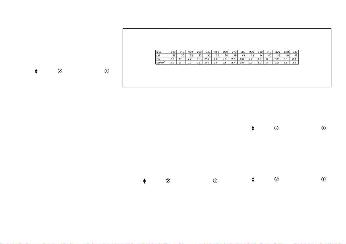
(98,1)
Tyre Pressure Unit:
The unit for tire pressure that displays in the
vehicle information display can be changed to:
. kPa
. bar
. psi
. Kgf/cm2
Use the
select and change the unit.
If necessary, refer to the following table to
convert between units.
button and the OK button to
Calibrate:
The tire pressure is affected by the temperature of the tire; the tire temperature increases
when the car is driven. To be able to accurately
monitor the tire air leakage and to prevent false
TPMS warnings due to changes in temperature,
the TPMS system uses temperature sensors in
the tires to perform temperature compensation calculations.
On rare occasions it may be necessary to
recalibrate the TPMS system reference temperature. This operation should only be performed when the actual tire pressure has been
adjusted, while the current ambient temperature is significantly different to the current
calibration temperature. (See “Tire Pressure
Monitoring System (TPMS)” (P.5-9).)
Use the
start or cancel the calibration process. While
the calibration process is active, the message:
“Resetting tyre pressure system” will be displayed.
button , and the OK button to
JVI0938X
Units (if equipped)
The units that are shown in the vehicle
information display can be changed:
. Distance/Fuel
. Tyre pressures (if equipped)
. Temperature
Use the
select and change the units of the vehicle
information display.
Distance/Fuel:
The unit for the mileage that displays in the
vehicle information display can be changed to:
. km, l/100km
. km, km/l
. miles, MPG (if equipped)
Use the
select and change the unit.
Tyre pressures (if equipped):
See “Tyre Pressure Unit” (P.2-28).
button , and the OK button to
button and the OK button to
2-28 Instruments and controls
Page 99

(99,1)
Temperature:
The temperature that displays in the vehicle
information display can be changed from:
. °C (Celsius)
. °F (Fahrenheit)
Use the
button to toggle choices.
Language (if equipped)
The language of the vehicle information display
can be changed.
Use the
select and change the language of the vehicle
information display. The language of the center
display/navigation can be changed independently of the vehicle information display. For
models with Navigation System, see “Vehicle
information and settings (for type D audio)”
(P.4-5) or the NissanConnect Owner’s Manual.
For models without Navigation System, see
“Audio system” (P.4-39) or the NissanConnect
Owner’s Manual.
button , and the OK button to
Factory Reset
The settings in the vehicle information display
can be reset back to the factory default. To
reset the vehicle information display:
1. Select “Factory Reset” using the
and press the OK button .
2. Select “YES” to return all settings back to
default by pressing the OK button
button
.
Instruments and controls 2-29
Page 100
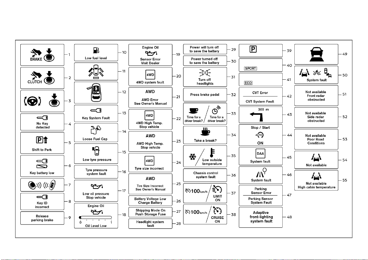
(100,1)
VEHICLE INFORMATION DISPLAY WARNINGS AND INDICATORS
2-30 Instruments and controls
WAC0079X
 Loading...