

Page 1
Page 11850
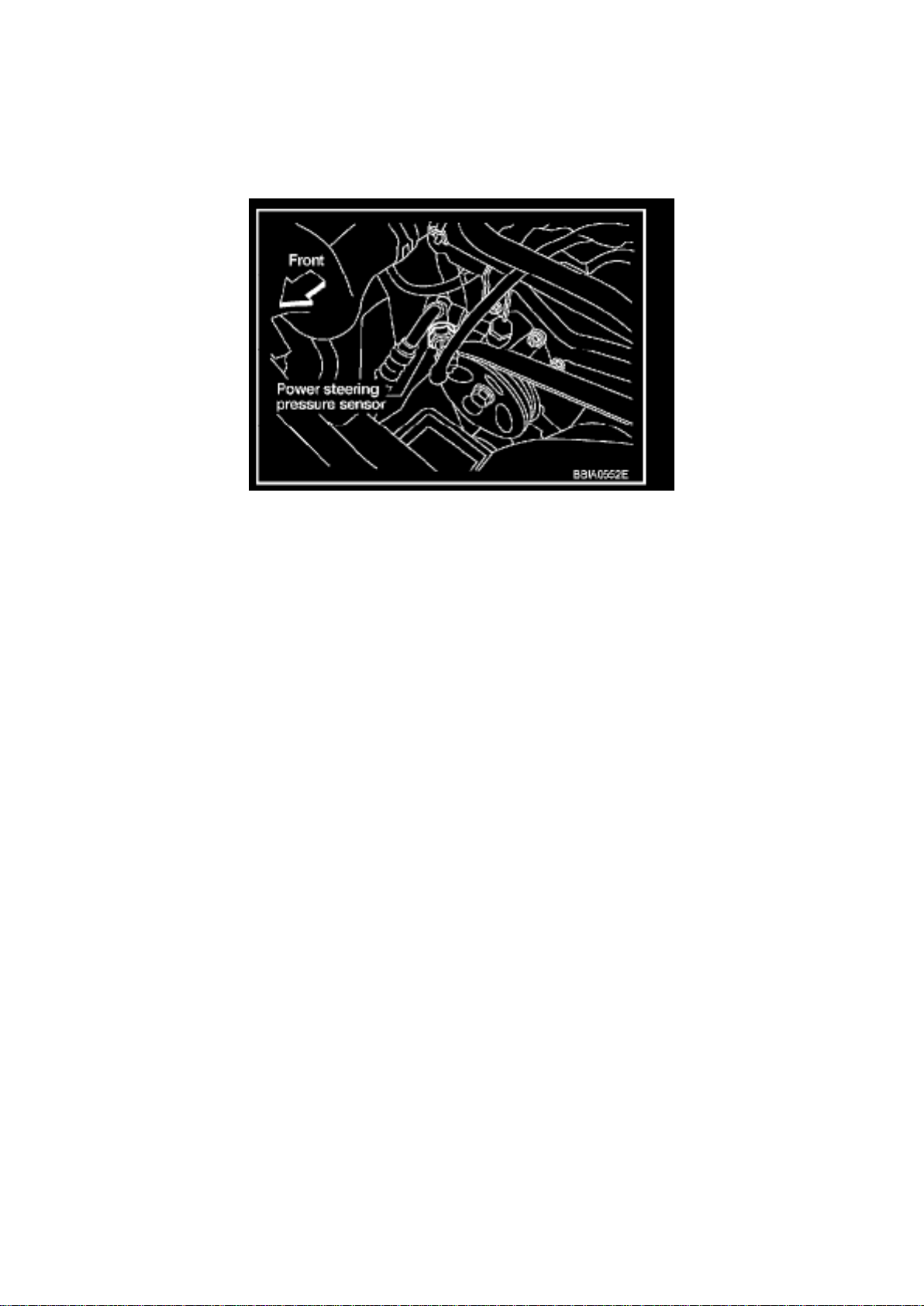
Power Steering Pressure Switch: Description and Operation
PSP SENSOR
Component Description
Power steering pressure (PSP) sensor is installed to the power steering high-pressure tube and
detects a power steering load. This sensor is a potentiometer which transforms the power steering
load into output voltage, and emits the voltage signal to the ECM. The ECM controls the electric
throttle control actuator and adjusts the throttle valve opening angle to increase the engine speed
and adjusts the idle speed for the increased load.
Page 2

Page 913
Page 3
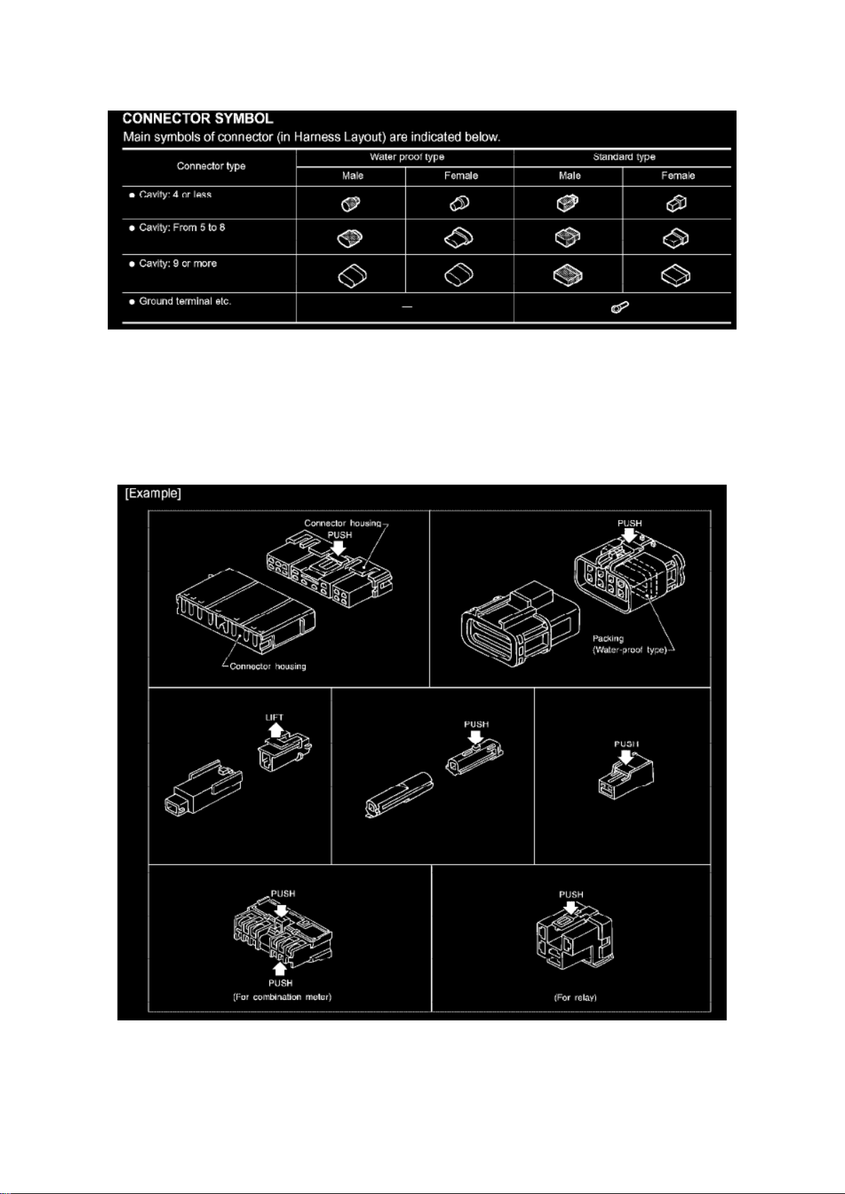
CONNECTOR SYMBOL
Page 4

Harness Connector Descriptions
HARNESS CONNECTOR
Description
HARNESS CONNECTOR (TAB-LOCKING TYPE)
- The tab-locking type connectors help prevent accidental looseness or disconnection.
- The tab-locking type connectors are disconnected by pushing or lifting the locking tab(s). Refer to
the illustration given.
CAUTION: Do not pull the harness or wires when disconnecting the connector.
Page 5
Page 6773
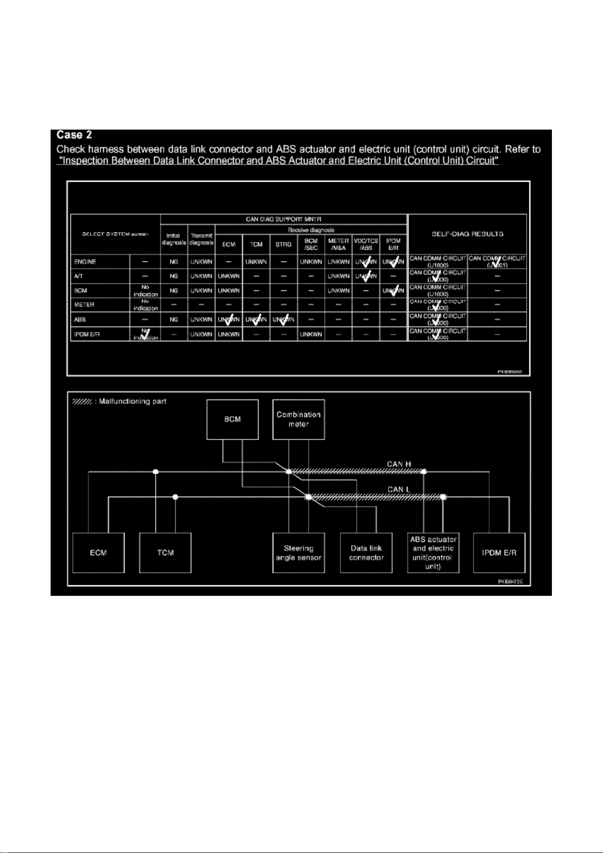
Case 2
Page 6

Engine Controls - MIL ON/DTC's
P1273/P1283/P1274/P1284
Page 7

Engine Control Module: All Technical Service Bulletins Engine Controls - MIL ON/DTC's
P1273/P1283/P1274/P1284
Page 8

Classification: EC04-025
Reference: NTB04-126
Date: October 29, 2004
MUST CLEAR SELF-LEARNING AFTER REPAIRING DTC P1273/P1283 OR P1274/P1284 AIR
FUEL LEAN OR RICH SHIFT
APPLIED VEHICLES: All Nissan's with DTC's P1273/P1274/P1283/P1284
IF YOU CONFIRM:
A MIL "ON" with any of the following DTC(s) stored:
^ P1273/P1283 (A/F Sensor Bank-1/2-Lean Monitor)
^ P1274/P1284 (A/F Sensor Bank-1/2-Rich Monitor)
ACTIONS:
1. Repair the vehicle as necessary.
^ Refer to ASIST for diagnostic and repair information.
2. Clear the engine ECU Self-Learning.
IMPORTANT:
If Self-Learning Is Not Cleared:
^ The DTC may be stored again; even if no malfunction exists.
^ This could result in the customer returning with the same incident ("come-back" repair).
CLAIMS INFORMATION
The procedure to clear ECU Self-Learning is part of the DTC repair and should not be claimed as a
separate repair item.
IMPORTANT:
The purpose of ACTIONS (above) is to give you a quick idea of the work you will be performing.
You MUST closely follow the entire Service Procedure as it contains information that is essential to
successfully completing this repair.
SERVICE PROCEDURE
1. Repair the source of the lean condition (P1273/P1283) or rich condition (P1274/P1284).
^ Check ASIST for any specific incident bulletins that may apply to your vehicle.
^ As necessary, follow Service Manual (ESM) diagnostic and repair information.
Page 9

Page 10761
Page 10

Steering Angle Sensor: Service and Repair
Page 11

Removal and Installation
NOTE: The steering angle sensor is an integral part of the spiral cable.
- If the ABS actuator and electronic unit (control unit) is replaced, make sure to adjust position of
steering angle sensor. Refer to "Adjustment of Steering Angle Sensor Neutral Position". See:
Adjustments
Page 12

Page 8375
Page 13
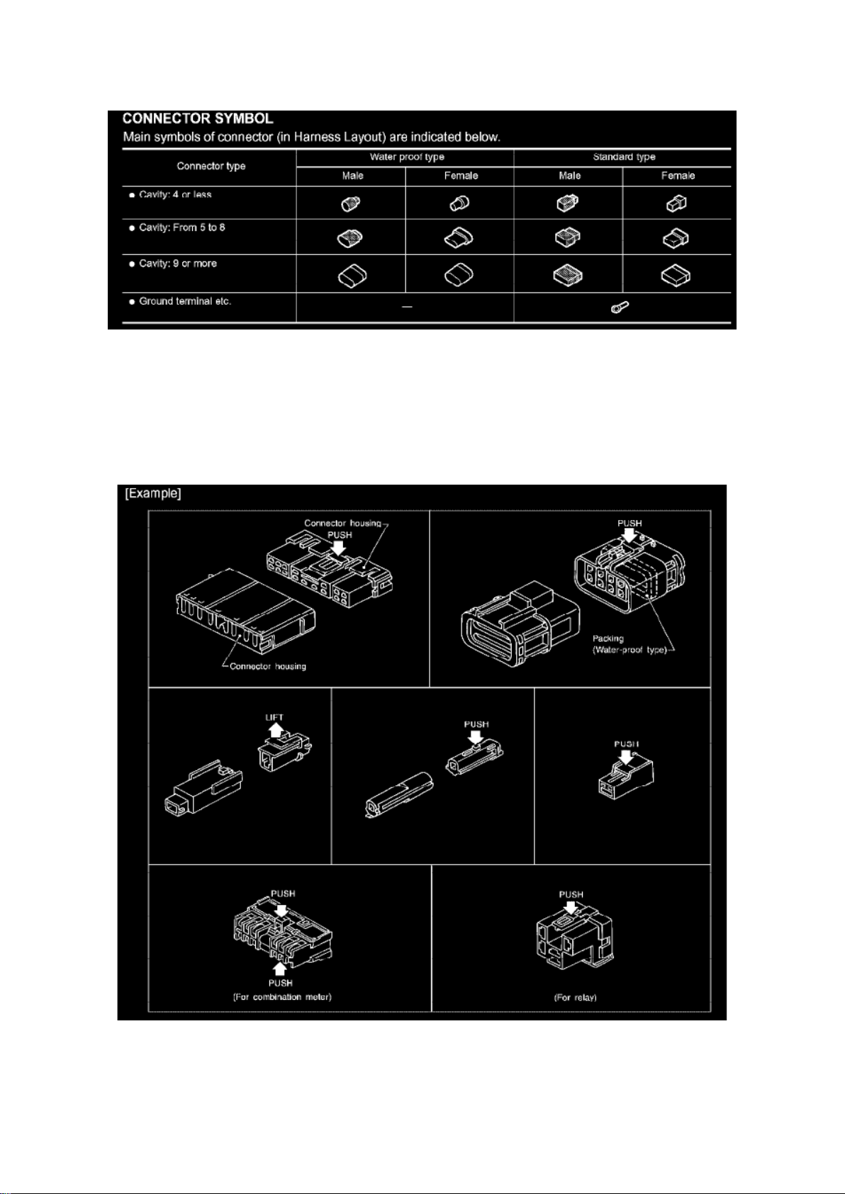
CONNECTOR SYMBOL
Page 14

Harness Connector Descriptions
HARNESS CONNECTOR
Description
HARNESS CONNECTOR (TAB-LOCKING TYPE)
- The tab-locking type connectors help prevent accidental looseness or disconnection.
- The tab-locking type connectors are disconnected by pushing or lifting the locking tab(s). Refer to
the illustration given.
CAUTION: Do not pull the harness or wires when disconnecting the connector.
Page 15
Page 14332
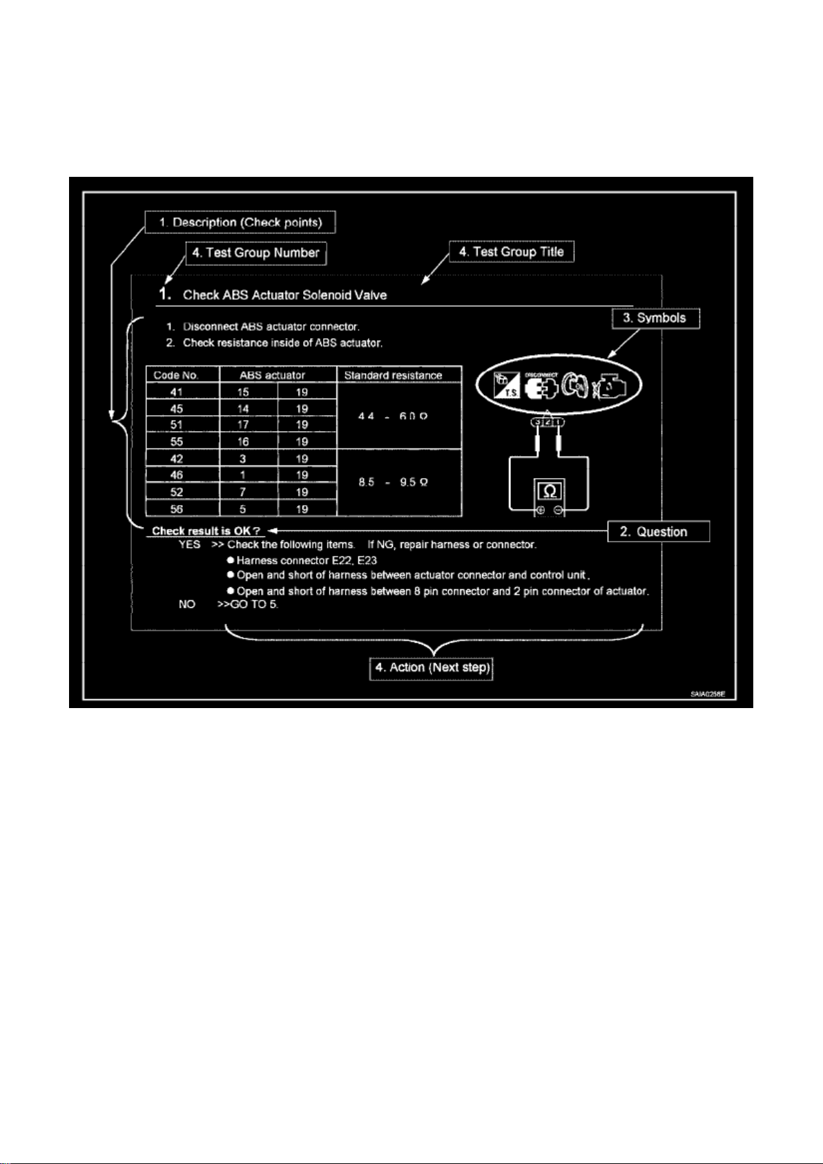
HOW TO FOLLOW TEST GROUPS IN TROUBLE DIAGNOSIS
1. Work and diagnostic procedure
Start to diagnose a problem using procedures indicated in enclosed test groups.
2. Questions and required results
Questions and required results are indicated in bold type in test group. The meaning of are as
follows:
a. Battery voltage -> 11 - 14 V or approximately 12 V b. Voltage: Approximately 0 V -> Less than 1
V
3. Symbol used in illustration
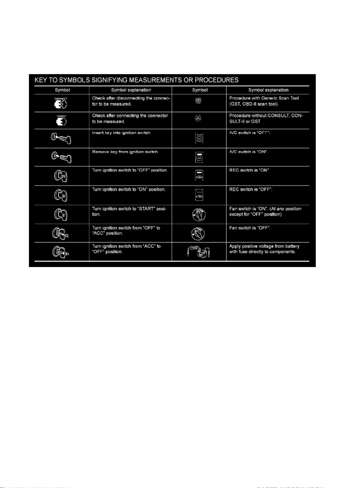
Symbols included in illustrations refer to measurements or procedures. Before diagnosing a
problem, familiarize yourself with each symbol. Refer to "Connector Symbols" in General
Information and "KEY TO SYMBOLS SIGNIFYING MEASUREMENTS OR PROCEDURES".
Page 16

4. Action items
Next action for each test group is indicated based on result of each question. Test group number is
shown in the left upper portion of each test group.
HARNESS WIRE COLOR AND CONNECTOR NUMBER INDICATION
There are two types of harness wire color and connector number indication.
Type 1: Harness Wire Color And Connector Number Are Shown In Illustration
Page 17
Page 4607
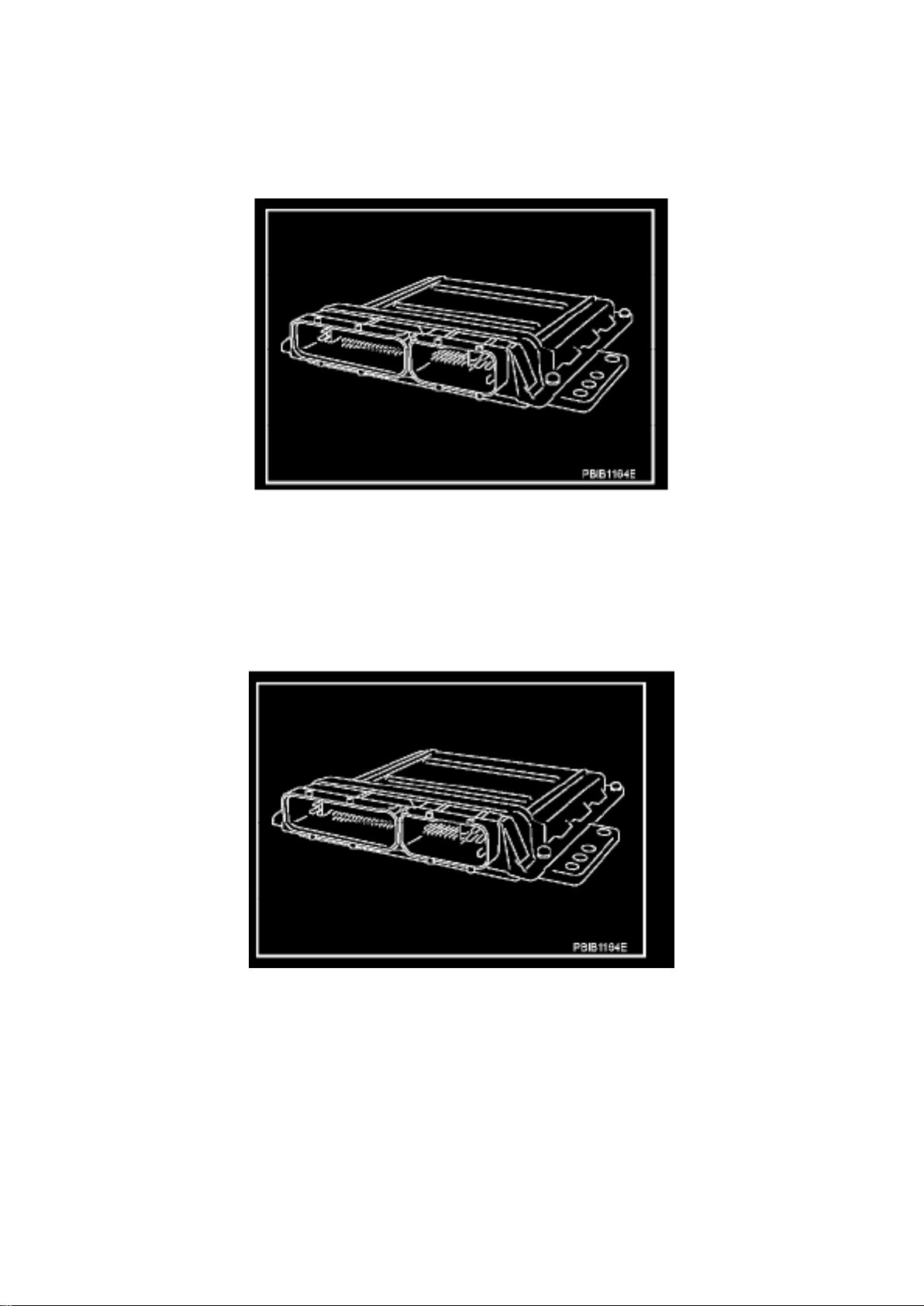
Engine Control Module: Description and Operation
ECM
Component Description
The ECM consists of a microcomputer and connectors for signal input and output and for power
supply. The ECM controls the engine.
ECM POWER SUPPLY
Page 18

Component Description
Battery voltage is supplied to the ECM even when the ignition switch is turned OFF for the ECM
memory function of the DTC memory, the air-fuel ratio feedback compensation value memory, the
idle air volume learning value memory, etc.
Page 19
Page 8043
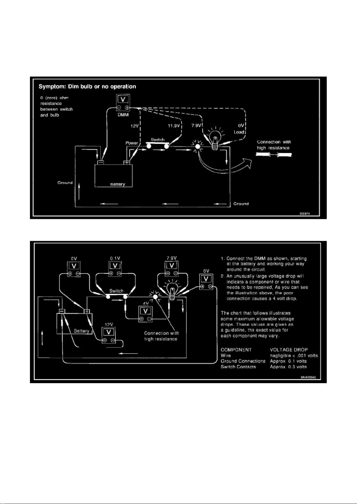
Unwanted resistance can be caused by many situations as follows:
- Undersized wiring (single strand example)
- Corrosion on switch contacts
- Loose wire connections or splices.
If repairs are needed always use wire that is of the same or larger gauge.
Page 20

MEASURING VOLTAGE DROP - ACCUMULATED METHOD
- Connect the DMM across the connector or part of the circuit you want to check. The positive lead
of the DMM should be closer to power and the negative lead closer to ground.
- Operate the circuit.
- The DMM will indicate how many volts are being used to "push" current through that part of the
circuit.
Note in the illustration that there is an excessive 4.1 volt drop between the battery and the bulb.
MEASURING VOLTAGE DROP - STEP-BY-STEP
The step-by-step method is most useful for isolating excessive drops in low voltage systems (such
as those in "Computer Controlled Systems"). Circuits in the "Computer Controlled System" operate
on very low amperage. The (Computer Controlled) system operations can be adversely affected by
any variation in resistance in the system. Such resistance variation may be caused by poor
connection, improper installation, improper wire gauge or corrosion. The step by step voltage drop
test can identify a component or wire with too much resistance.
Page 21

Page 2552
Page 22
CONSULT-II Data Link Connector (DLC) Circuit
Page 23

INSPECTION PROCEDURE
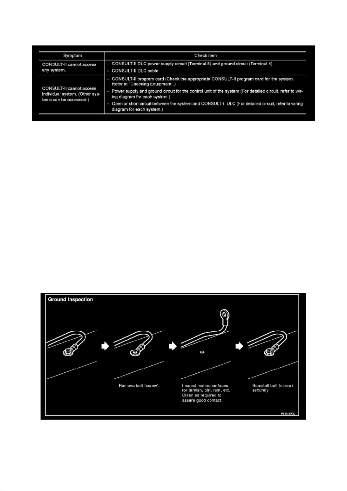
If the CONSULT-II cannot diagnose the system properly, check the given items.
NOTE: The DDL1 and DDL2 circuits from DLC pins 12, 13, 14 and 15 may be connected to more
than one system. A short in a DDL circuit connected to a control unit in one system may affect
CONSULT-II access to other systems.
Ground Inspection
Ground Inspection
Ground connections are very important to the proper operation of electrical and electronic circuits.
Ground connections are often exposed to moisture, dirt and other corrosive elements. The
corrosion (rust) can become an unwanted resistance. This unwanted resistance can change the
way a circuit works.
Electronically controlled circuits are very sensitive to proper grounding. A loose or corroded ground
can drastically affect an electronically controlled circuit. A poor or corroded ground can easily affect
the circuit. Even when the ground connection looks clean, there can be a thin film of rust on the
surface.
When inspecting a ground connection follow these rules:
- Remove the ground bolt or screw.
- Inspect all mating surfaces for tarnish, dirt, rust, etc.
- Clean as required to assure good contact.
- Reinstall bolt or screw securely.
- Inspect for "add-on" accessories which may be interfering with the ground circuit.
- If several wires are crimped into one ground eyelet terminal, check for proper crimps. Make sure
all of the wires are clean, securely fastened and providing a good ground path. If multiple wires are
cased in one eyelet make sure no ground wires have excess wire insulation.
For detailed ground distribution information, refer to "Ground Distribution".
How to Check Terminals
SERVICE INFORMATION FOR ELECTRICAL INCIDENT
Page 24

Page 13568
Page 25
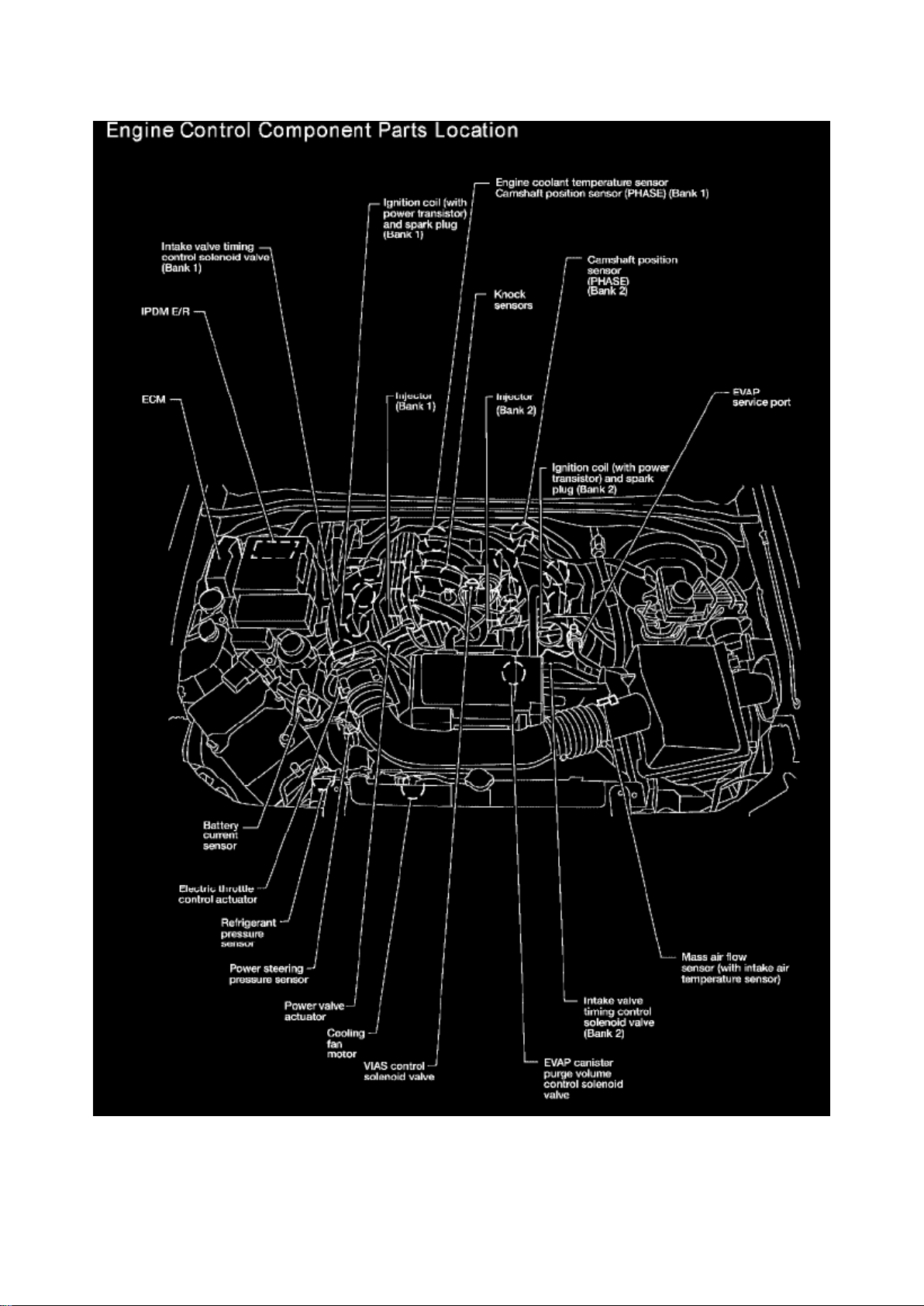
Engine Control Component Parts Location Part 1
Page 26
Page 8310
14. Coat/spray the bracket bolt and the frame around the bolt with Nissan Bitumen Wax (P/N
999MP-9G001P).
15. Reinstall the EVAP canister mounting bolt.
16. Clear any DTCs stored in the ECM.
Disclaimer
Page 27
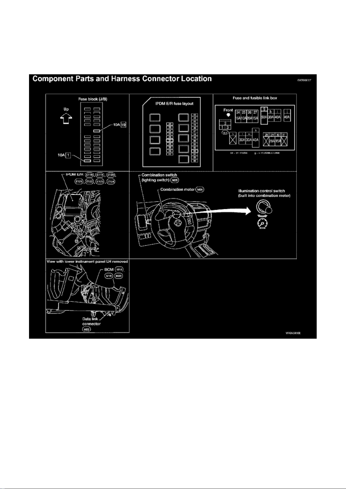
Locations
Component Parts And Harness Connector Location
Page 28
Page 7556
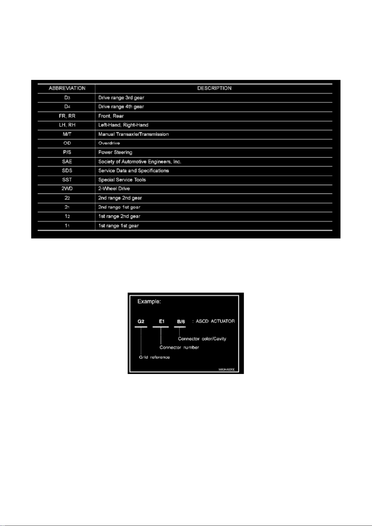
Abbreviations
How to Read Harness Layout
Harness Layout
HOW TO READ HARNESS LAYOUT
The following Harness Layouts use a map style grid to help locate connectors on the drawings:
- Main Harness
Page 29

- Engine Room Harness RH View (Engine Compartment), Generator Sub-harness, and Trailer Tow
Relay Sub-harness
- Engine Room Harness (Passenger Compartment)
- Engine Room Harness LH View (Engine Compartment)
- Engine Control Harness
- Chassis Harness
- Body Harness
- Body No. 2 Harness
- Room Lamp Harness
- Back Door Harness
- Back Door No. 2 Harness
- Rear Window Sub-Harness
- Rear Window Defogger Sub-Harness
To use the grid reference
1. Find the desired connector number on the connector list. 2. Find the grid reference. 3. On the
drawing, find the crossing of the grid reference letter column and number row. 4. Find the
connector number in the crossing zone. 5. Follow the line (if used) to the connector.
Page 30
Page 11472
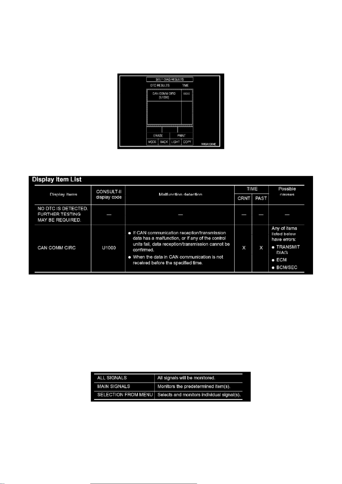
Power Distribution Module: Scan Tool Testing and Procedures
Self-Diagnostic Results
Page 31

SELF-DIAGNOSTIC RESULTS
Operation Procedure
1. Touch "SELF-DIAG RESULTS" on "SELECT DIAG MODE" screen. 2. Self-diagnosis results are
displayed.
Display Item List
NOTE:
The details for display of the period are as follows:
- CRNT: Error currently detected with IPDM E/R.
- PAST: Error detected in the past and placed in IPDM E/R memory.
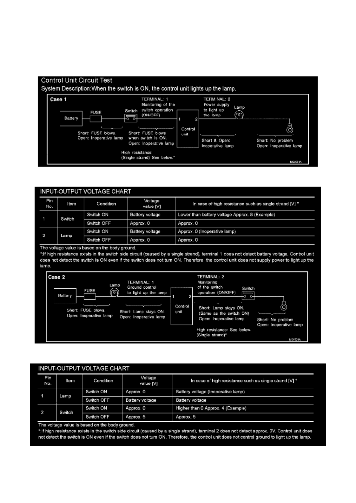
Data Monitor
DATA MONITOR
Operation Procedure
1. Touch "DATA MONITOR" on "SELECT DIAG MODE" screen.
2. Touch "ALL SIGNALS", "MAIN SIGNALS" or "SELECTION FROM MENU" on the "DATA
MONITOR" screen. 3. Touch "START". 4. Touch the required monitoring item on "SELECT ITEM
MENU". 5. Touch "RECORD" while monitoring to record the status of the item being monitored. To
stop recording, touch "STOP".
Page 32
Page 8616
Page 33

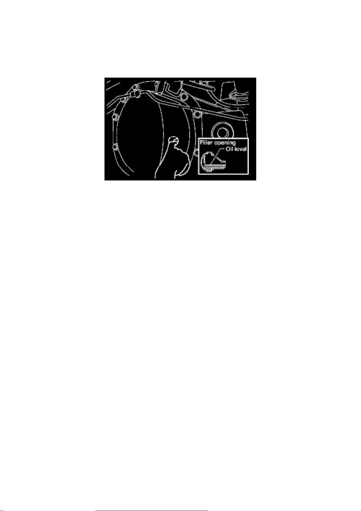
Control Unit Circuit Test
INPUT-OUTPUT VOLTAGE CHART
INPUT-OUTPUT VOLTAGE CHART
Control Units and Electrical Parts
PRECAUTIONS
Page 34
Page 9924
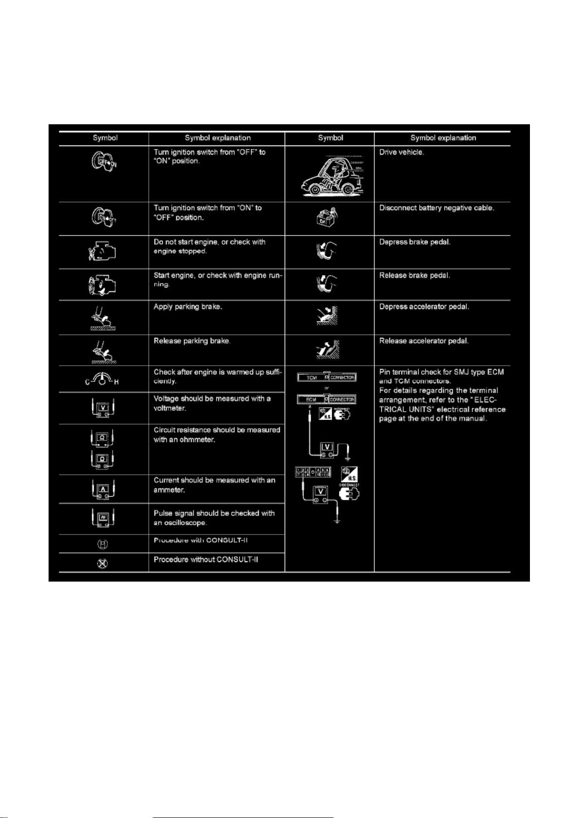
2. Check oil level from filler plug hole as shown.
CAUTION: Do not start engine while checking oil level.
3. Apply sealant to filler plug. Install filler plug to final drive assembly and tighten to the specified
torque. Refer to "COMPONENTS".
^ Use Genuine Silicone RTV or equivalent. Refer to "Recommended Chemical Products and
Sealants".
Page 35
Page 4577
KEY TO SYMBOLS SIGNIFYING MEASUREMENTS OR PROCEDURES
How to Perform Efficient Diagnosis For an Electrical Incident
How to Perform Efficient Diagnosis for an Electrical Incident
Page 36

Page 3704
Page 37
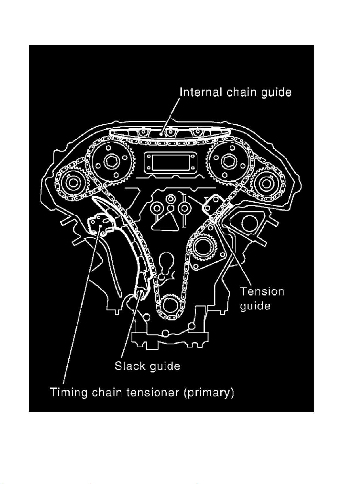
Mating mark (F) Yellow link Copper link
Page 38

- When it is difficult to align mating marks (A) with (B) and (E) with (F) of the primary timing chain
with each sprocket, gradually turn the
camshaft to align it with the mating marks.
- During alignment, be careful to prevent dislocation of mating mark alignments of the secondary
timing chains.
4. Install internal chain guide.
Page 39

Page 5484
Page 40
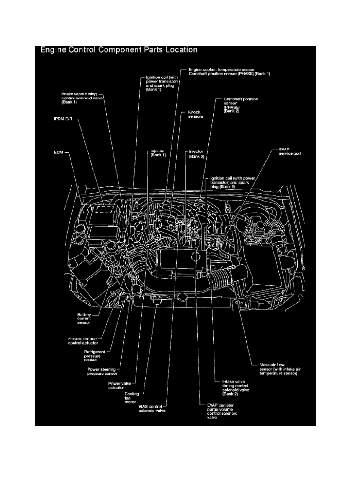
Engine Control Component Parts Location Part 1
Page 41

Page 751
Page 42
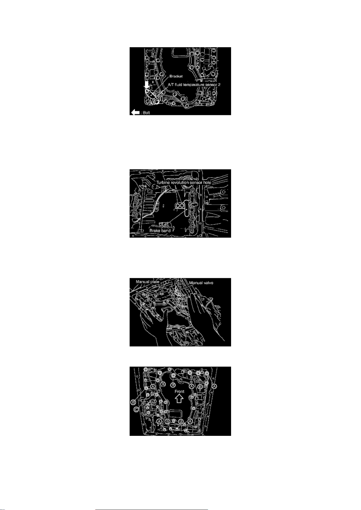
5. Install A/T fluid temperature sensor 2 to bracket.
Page 43

6. Install A/T fluid temperature sensor 2 with bracket in control valve with TCM. Tighten A/T fluid
temperature sensor 2 bolt to the specified torque.
Refer to AT-234, "COMPONENTS".
CAUTION: Adjust bolt hole of bracket to bolt hole of control valve with TCM.
7. Install control valve with TCM in transmission case.
CAUTION: ^
Make sure that turbine revolution sensor is securely installed into turbine revolution sensor hole.
^ Hang down revolution sensor harness toward outside so as not to disturb installation of control
valve with TCM.
^ Adjust A/T assembly harness connector of control valve with TCM to terminal hole of
transmission case.
^ Assemble it so that manual valve cutout is engaged with manual plate projection.
8. Install bolts A, B and C in control valve with TCM.
Page 44

Page 5855
Page 45
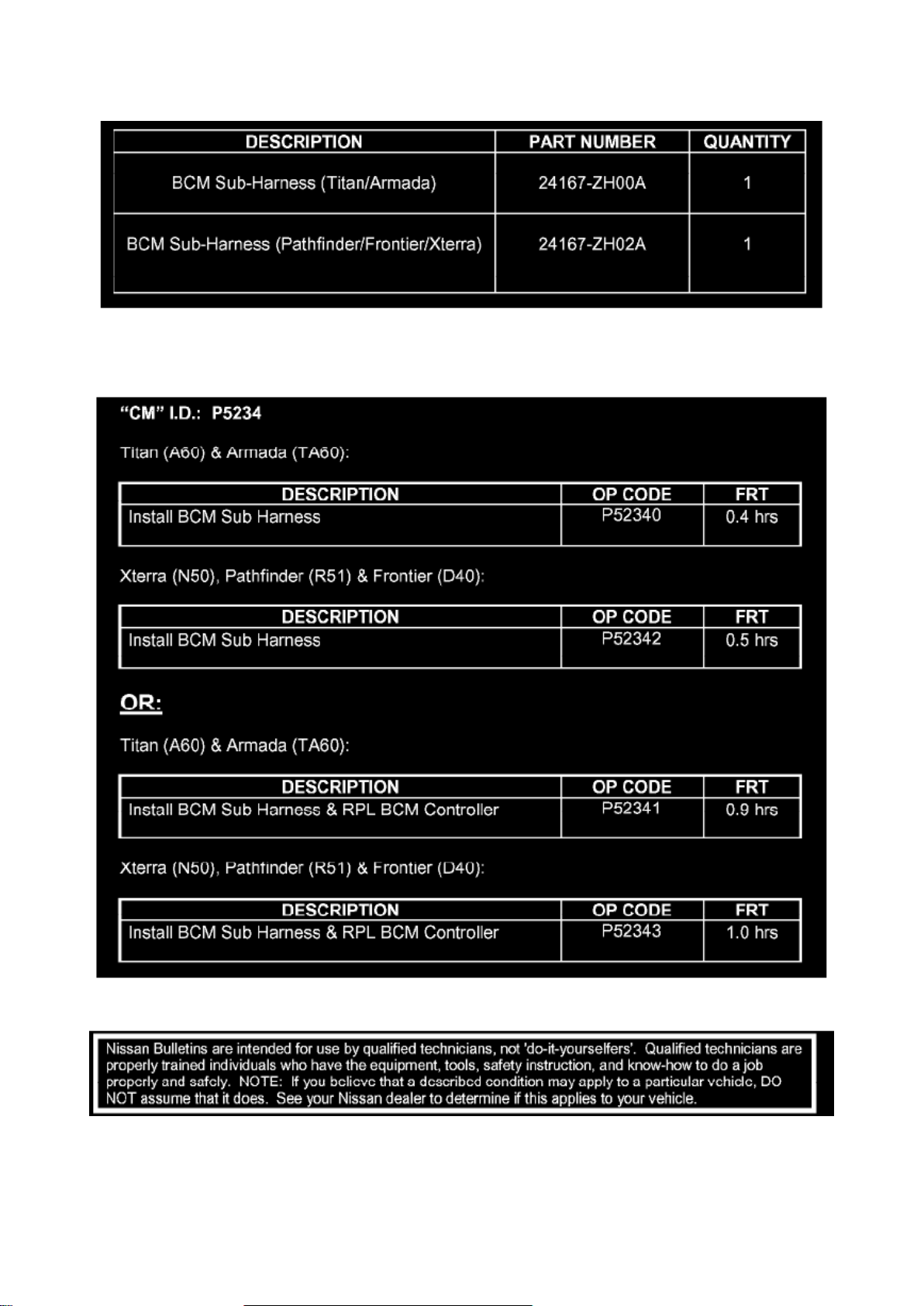
PARTS INFORMATION
Page 46

CLAIMS INFORMATION
Submit a Campaign (CM) line claim using the claims coding shown.
Disclaimer
Procedure A
PROCEDURE A: TRAILER LIGHTS WIRING CONNECTOR TERMINAL CHECK
Check the condition of the BCM by performing a terminal check at the Trailer Lights Wiring
Connector (near the trailer hitch) as follows.
Procedure A (Terminal Check) is split up into two sections:
^ Section 1: For vehicles with a 4-terminal Trailer Lights Wiring Connector.
Page 47

Page 9986
Page 48

Tool number: ST3127S000 (J-25765-A)
Page 49

5. If the rotating torque is low, continue to tighten the drive pinion nut in 6.8 Nm (5 ft. lbs.)
increments without overtightening. Refer to
COMPONENTS. Tighten until proper rotating torque is achieved.
CAUTION: ^
Do not loosen the drive pinion nut to decrease drive pinion rear bearing rotating torque.
^ Do not exceed specified rotating preload torque. If preload torque or rotating torque is exceeded
a new collapsible spacer must be installed.
^ Do not exceed maximum tightening torque. If maximum tightening torque is reached prior to
reaching the required rotating torque, the collapsible spacer may have been damaged. Replace the
collapsible spacer.
6. Check the gear oil level. Refer to "Checking Differential Gear Oil". 7. Install the remaining
components in the reverse order of removal.
Page 50
Page 2368
- Start at one end of the circuit and work your way to the other end. (At the fuse block in this
example)
- Connect one probe of the DMM to the fuse block terminal on the load side.
- Connect the other probe to the fuse block (power) side of SW1. Little or no resistance will indicate
that portion of the circuit has good continuity. If there were an open in the circuit, the DMM would
indicate an over limit or infinite resistance condition. (point A)
- Connect the probes between SW1 and the relay. Little or no resistance will indicate that portion of
the circuit has good continuity. If there were an open in the circuit, the DMM would indicate an over
limit or infinite resistance condition. (point B)
- Connect the probes between the relay and the solenoid. Little or no resistance will indicate that
portion of the circuit has good continuity. If there were an open in the circuit, the DMM would
indicate an over limit or infinite resistance condition. (point C)
Any circuit can be diagnosed using the approach in the previous example.
VOLTAGE CHECK METHOD
To help in understanding the diagnosis of open circuits please refer to the previous schematic. In
any powered circuit, an open can be found by methodically checking the system for the presence
of voltage.
This is done by switching the DMM to the voltage function.
- Connect one probe of the DMM to a known good ground.
- Begin probing at one end of the circuit and work your way to the other end.
- With SW1 open, probe at SW1 to check for voltage. voltage; open is further down the circuit than
SW1. no voltage; open is between fuse block and SW1 (point A).
- Close SW1 and probe at relay. voltage; open is further down the circuit than the relay. no voltage;
open is between SW1 and relay (point B).
- Close the relay and probe at the solenoid. voltage; open is further down the circuit than the
solenoid. no voltage; open is between relay and solenoid (point C).
Any powered circuit can be diagnosed using the approach in the previous example.
Page 51

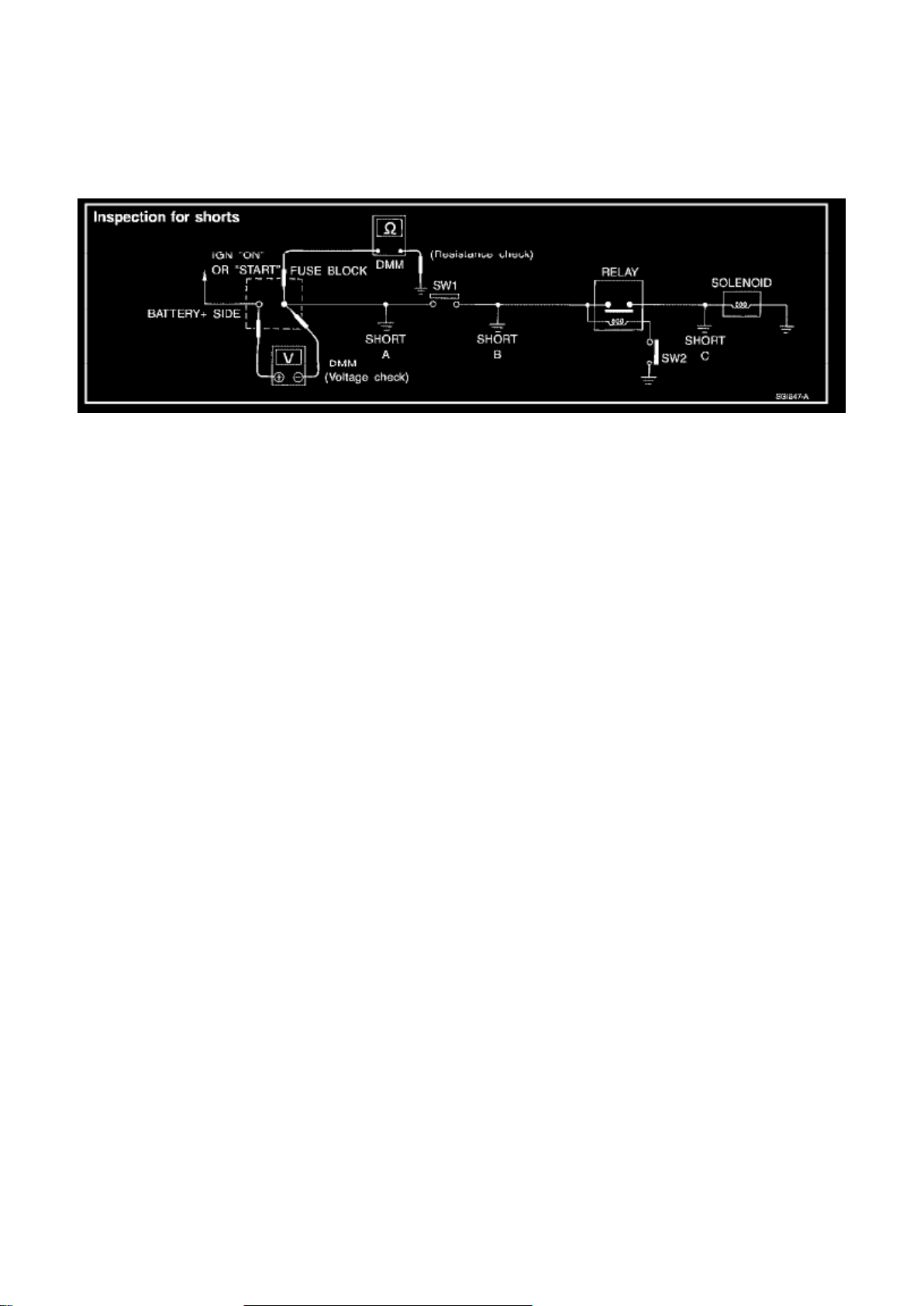
Testing for "Shorts" in the Circuit
To simplify the discussion of shorts in the system, please refer to the following schematic.
RESISTANCE CHECK METHOD
- Disconnect the battery negative cable and remove the blown fuse.
- Disconnect all loads (SW1 open, relay disconnected and solenoid disconnected) powered through
the fuse.
- Connect one probe of the DMM to the load side of the fuse terminal. Connect the other probe to a
known good ground.
- With SW1 open, check for continuity. continuity; short is between fuse terminal and SW1 (point
A). no continuity; short is further down the circuit than SW1.
- Close SW1 and disconnect the relay. Put probes at the load side of fuse terminal and a known
good ground. Then, check for continuity. continuity; short is between SW1 and the relay (point B).
no continuity; short is further down the circuit than the relay.
- Close SW1 and jump the relay contacts with jumper wire. Put probes at the load side of fuse
terminal and a known good ground. Then, check for continuity. continuity; short is between relay
and solenoid (point C). no continuity; check solenoid, retrace steps.
Page 52
Page 4731
- Start at one end of the circuit and work your way to the other end. (At the fuse block in this
example)
- Connect one probe of the DMM to the fuse block terminal on the load side.
- Connect the other probe to the fuse block (power) side of SW1. Little or no resistance will indicate
that portion of the circuit has good continuity. If there were an open in the circuit, the DMM would
indicate an over limit or infinite resistance condition. (point A)
- Connect the probes between SW1 and the relay. Little or no resistance will indicate that portion of
the circuit has good continuity. If there were an open in the circuit, the DMM would indicate an over
limit or infinite resistance condition. (point B)
- Connect the probes between the relay and the solenoid. Little or no resistance will indicate that
portion of the circuit has good continuity. If there were an open in the circuit, the DMM would
indicate an over limit or infinite resistance condition. (point C)
Any circuit can be diagnosed using the approach in the previous example.
VOLTAGE CHECK METHOD
To help in understanding the diagnosis of open circuits please refer to the previous schematic. In
any powered circuit, an open can be found by methodically checking the system for the presence
of voltage.
This is done by switching the DMM to the voltage function.
- Connect one probe of the DMM to a known good ground.
- Begin probing at one end of the circuit and work your way to the other end.
- With SW1 open, probe at SW1 to check for voltage. voltage; open is further down the circuit than
SW1. no voltage; open is between fuse block and SW1 (point A).
- Close SW1 and probe at relay. voltage; open is further down the circuit than the relay. no voltage;
open is between SW1 and relay (point B).
- Close the relay and probe at the solenoid. voltage; open is further down the circuit than the
solenoid. no voltage; open is between relay and solenoid (point C).
Any powered circuit can be diagnosed using the approach in the previous example.
Page 53

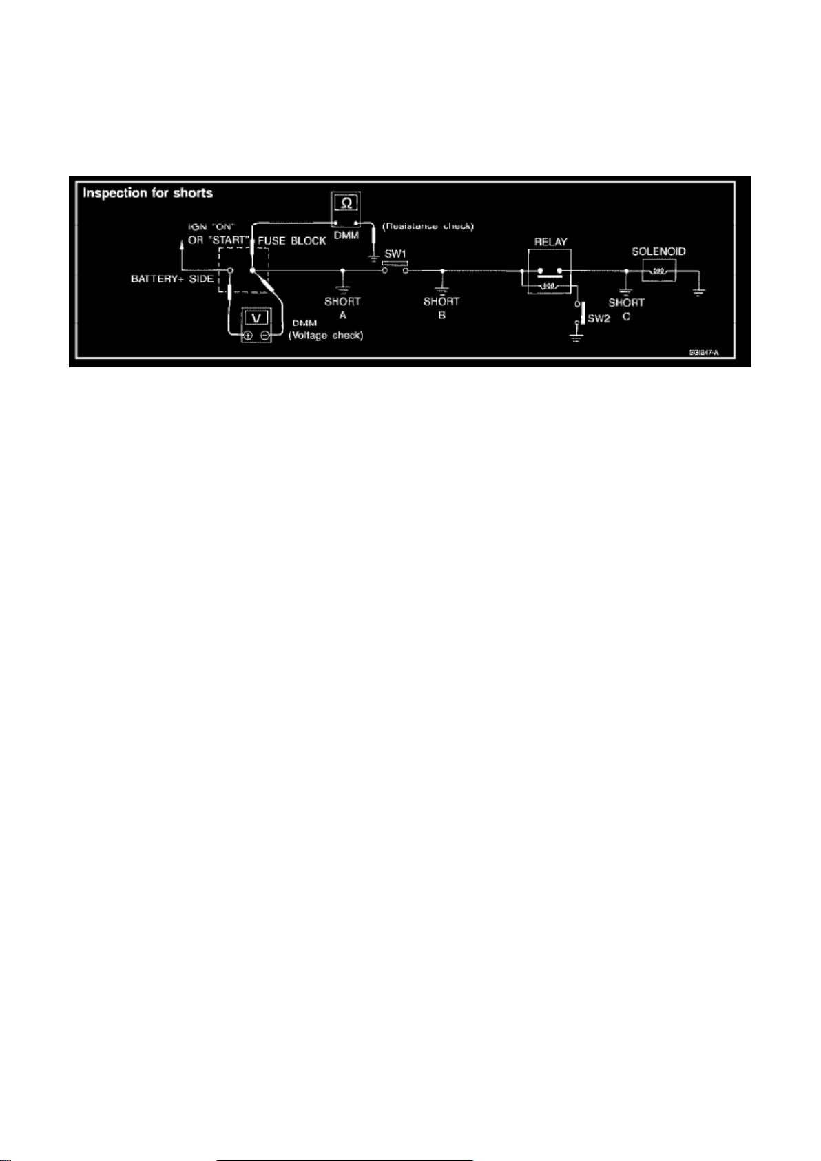
Testing for "Shorts" in the Circuit
To simplify the discussion of shorts in the system, please refer to the following schematic.
RESISTANCE CHECK METHOD
- Disconnect the battery negative cable and remove the blown fuse.
- Disconnect all loads (SW1 open, relay disconnected and solenoid disconnected) powered through
the fuse.
- Connect one probe of the DMM to the load side of the fuse terminal. Connect the other probe to a
known good ground.
- With SW1 open, check for continuity. continuity; short is between fuse terminal and SW1 (point
A). no continuity; short is further down the circuit than SW1.
- Close SW1 and disconnect the relay. Put probes at the load side of fuse terminal and a known
good ground. Then, check for continuity. continuity; short is between SW1 and the relay (point B).
no continuity; short is further down the circuit than the relay.
- Close SW1 and jump the relay contacts with jumper wire. Put probes at the load side of fuse
terminal and a known good ground. Then, check for continuity. continuity; short is between relay
and solenoid (point C). no continuity; check solenoid, retrace steps.
Page 54

Page 13080
Page 55
Optional Splice
Page 56

Part 1
Page 57

Page 13172
Page 58
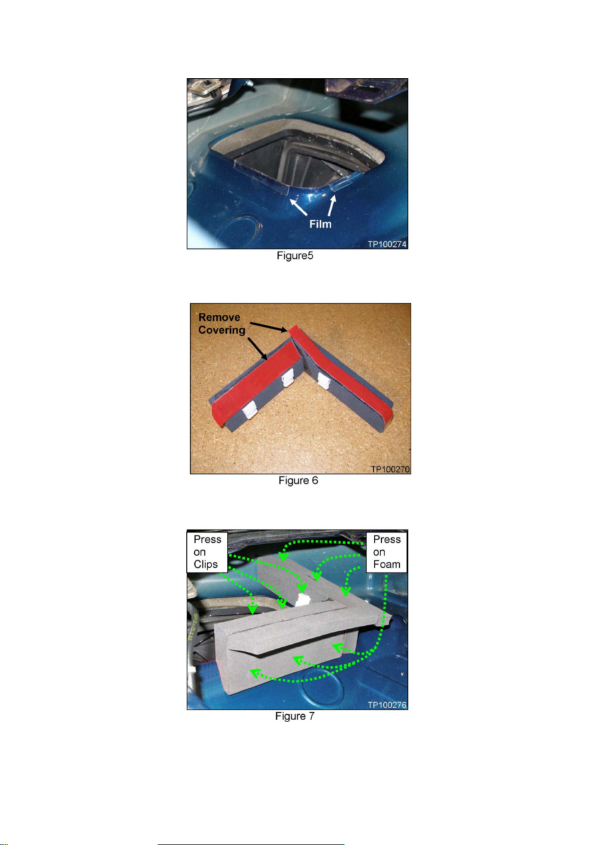
b. Apply the film: half on the inside, half on the outside (see Figure 5).
Page 59

6. Remove the remaining adhesive covering from the foam assembly (see Figure 6).
7. Put the foam assembly in position again (see Figure 7).
8. Carefully press down on each clip, securing it to the flange (see Figure 7).
^ Before pressing down, make sure the film is underneath each clip.
Page 60

Page 14285
Page 61
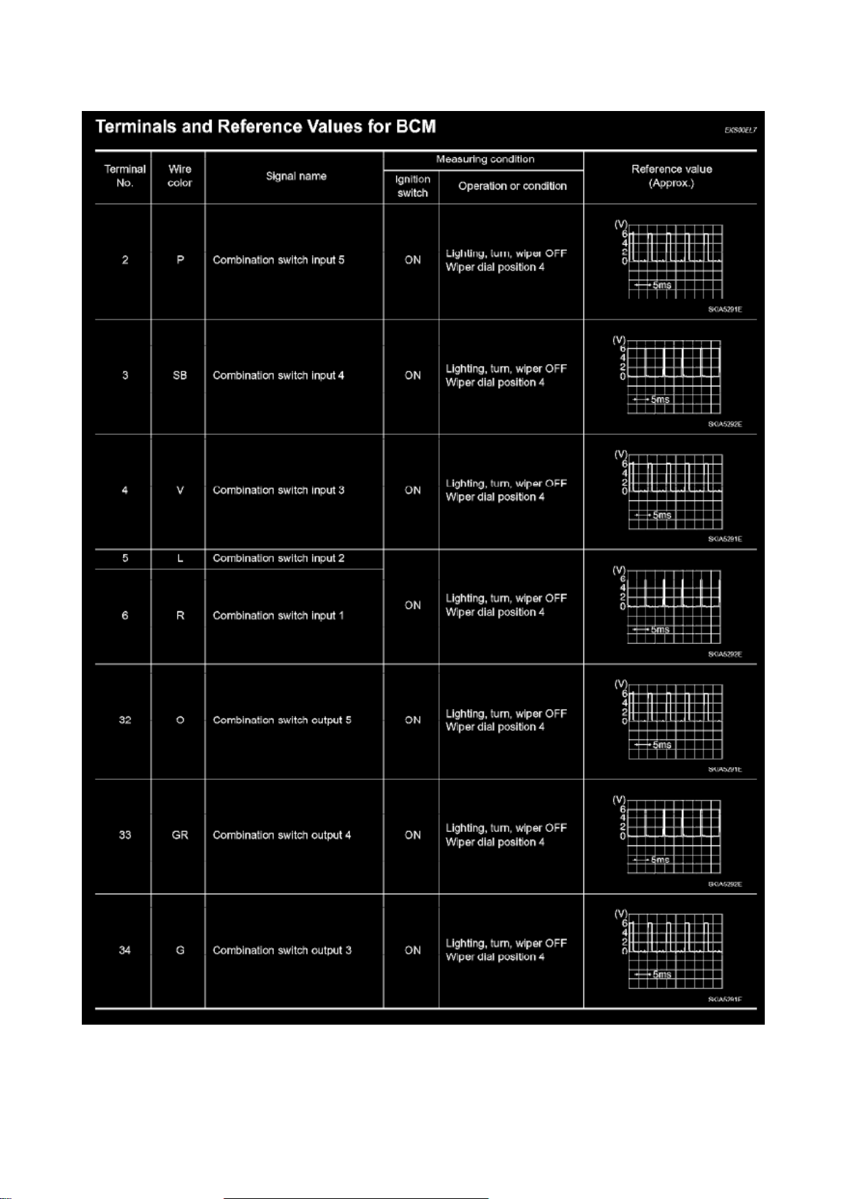
License Plate Lamp: Pinout Values and Diagnostic Parameters
Page 62

Terminals And Reference Values For BCM Part 1
Page 63

Page 8348
Page 64
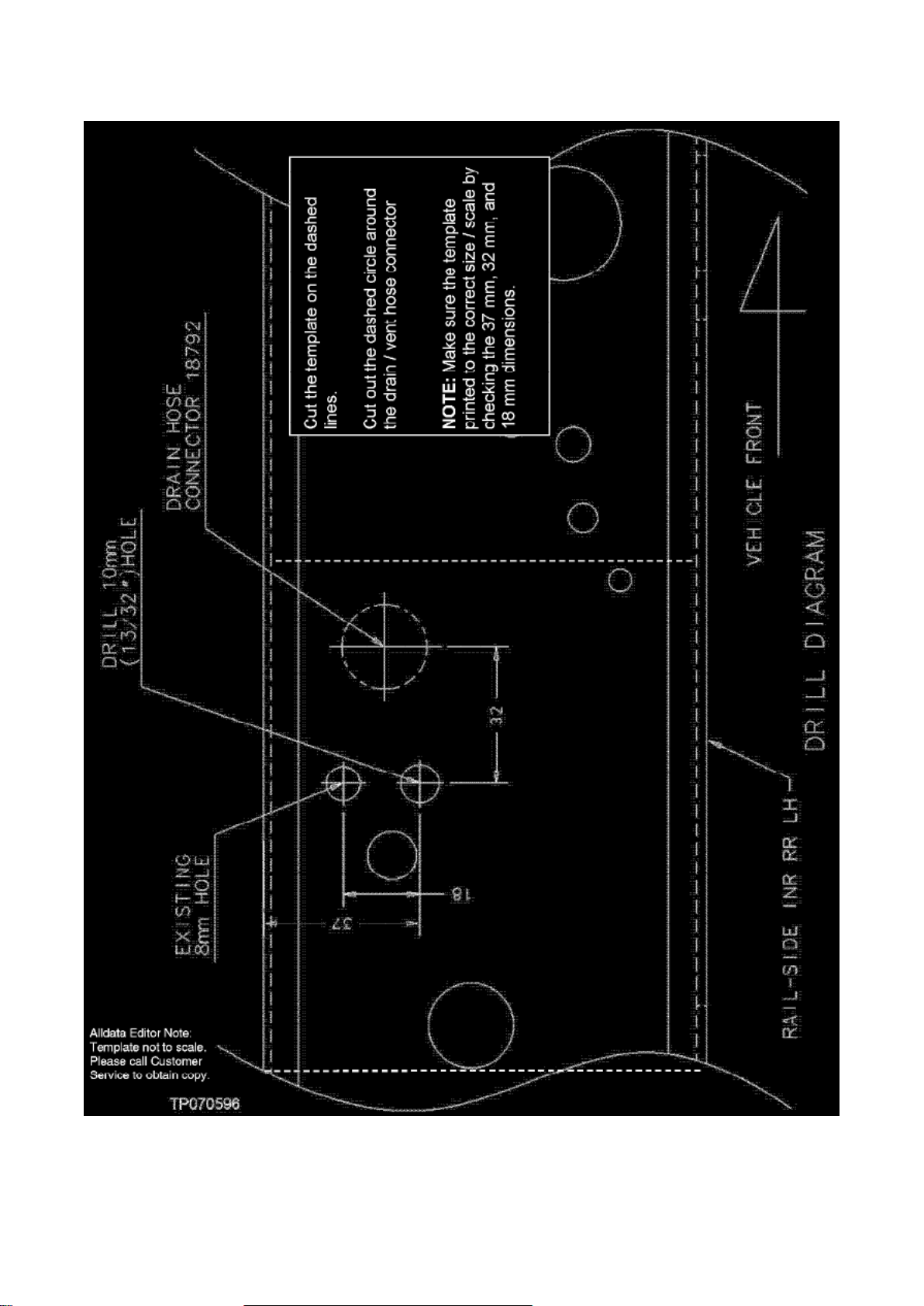
5. Cut out the template and place it on the frame rail as shown in Figure 3.
Page 65

^ Make sure the template is aligned (straight) with the frame rail.
6. Center punch and drill a 13/32 (10 mm) hole at the location shown.
7. Prep the hole you just drilled as follows:
Page 66

Page 639
Page 67
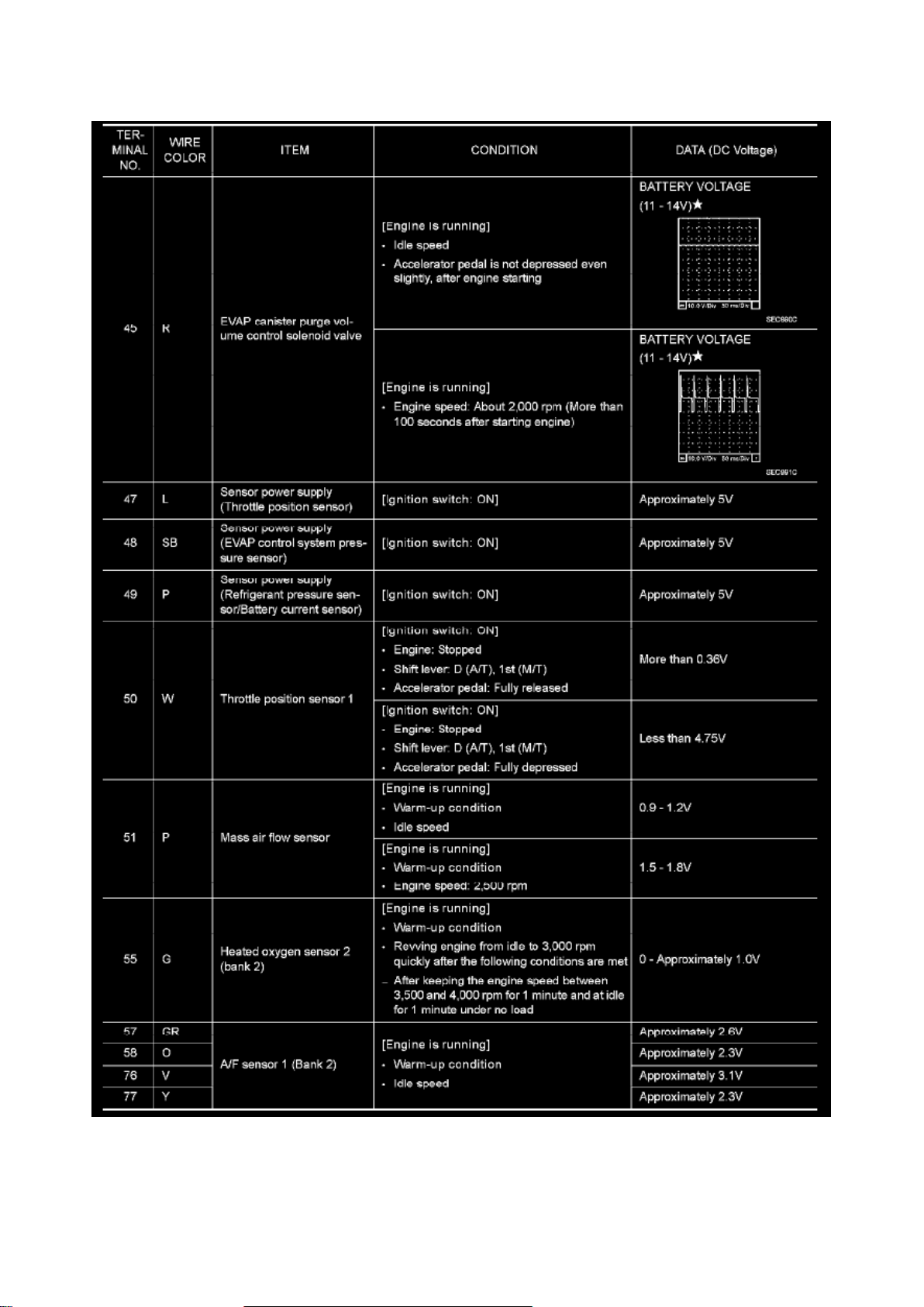
ECM Harness Connector Terminal Layout Part 6
Page 68

Page 4238
Page 69
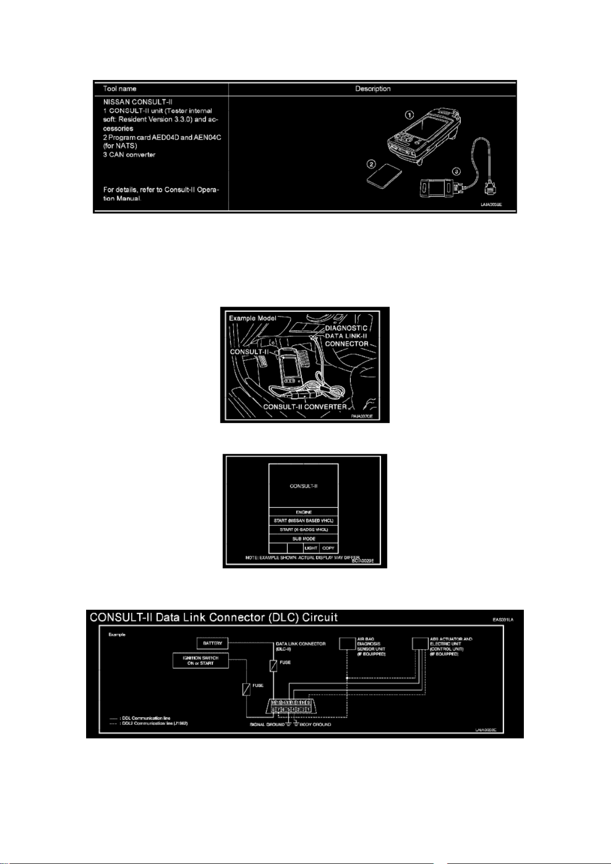
Checking Equipment
Page 70

When ordering the equipment, contact your NISSAN distributor.
CONSULT-II Start Procedure
NOTE: Turning ignition switch off when performing CAN diagnosis could cause CAN memory to be
erased.
1. Connect CONSULT-II and CONSULT-II CONVERTER to the data link connector.
2. If necessary, turn on the ignition switch. 3. Touch "START (NISSAN BASED VECL)" or "System
Shortcut ENGINE) on the screen.
Consult-II Data Link Connector (DLC) Circuit
Page 71
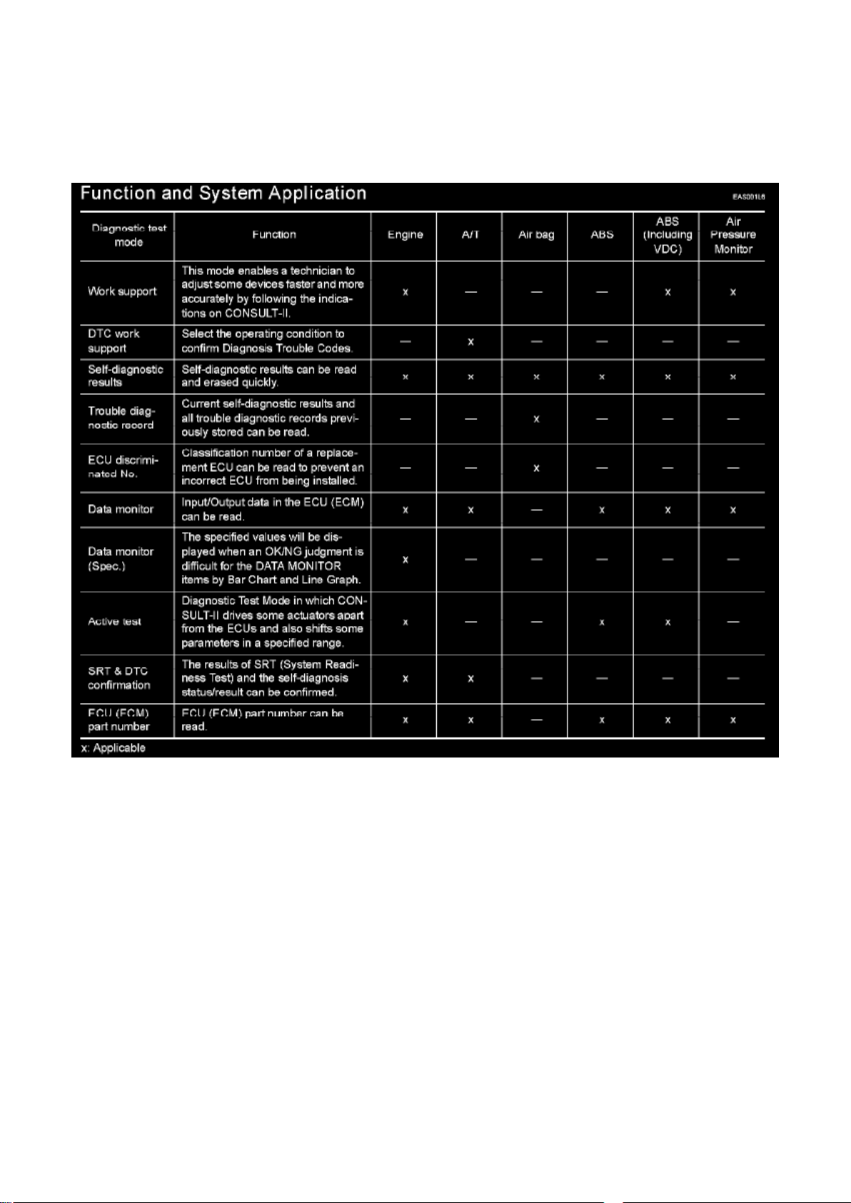
Page 5159
CONSULT-II Checking System
CONSULT-II CHECKING SYSTEM
Description
- CONSULT-II is a hand-held type tester. When it is connected with a diagnostic connector
equipped on the vehicle side, it will communicate with the control unit equipped in the vehicle and
then enable various kinds of diagnostic tests.
- Refer to "CONSULT-II Operator's Manual" for more information.
Function and System Application
Nickel Metal Hydride Battery Replacement
CONSULT-II contains a nickel metal hydride battery. When replacing the battery obey the
following:
Page 72

WARNING: Replace the nickel metal hydride battery with Genuine CONSULT-II battery only. Use
of another battery may present a risk of fire or explosion. The battery may present a fire or
chemical burn hazard if mistreated. Do not recharge, disassemble or dispose of in fire. Keep the
battery out of reach of children and discard used battery conforming to the local regulations.
Page 73

Page 13521
Page 74
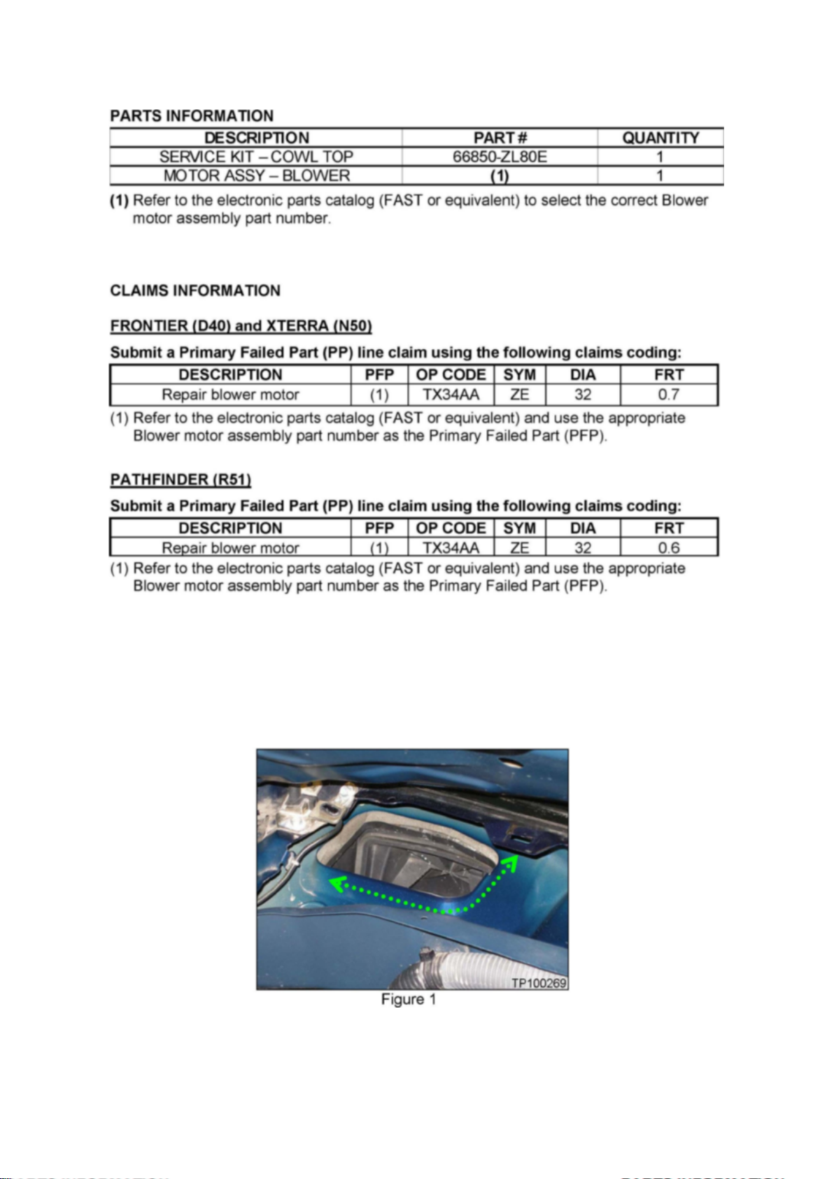
PARTS INFORMATION
Page 75

CLAIMS INFORMATION
SERVICE PROCEDURE
1. Remove the cowl top.
^ For removal procedure, refer to the appropriate section of the ESM, if needed.
2. Clean off the flange of the air intake hole (located at right side of cowl area) with a suitable
cleaner. See Figure 1.
Page 76
Page 7787
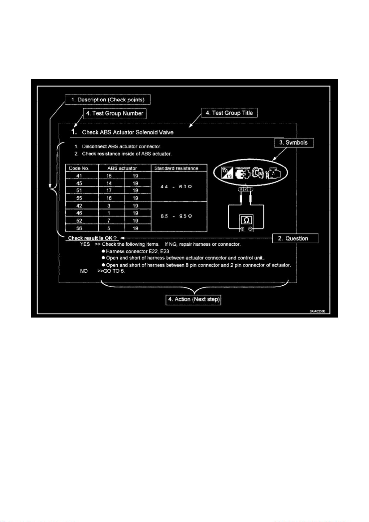
HOW TO FOLLOW TEST GROUPS IN TROUBLE DIAGNOSIS
1. Work and diagnostic procedure
Start to diagnose a problem using procedures indicated in enclosed test groups.
2. Questions and required results
Questions and required results are indicated in bold type in test group. The meaning of are as
follows:
a. Battery voltage -> 11 - 14 V or approximately 12 V b. Voltage: Approximately 0 V -> Less than 1
V
3. Symbol used in illustration
Symbols included in illustrations refer to measurements or procedures. Before diagnosing a
problem, familiarize yourself with each symbol. Refer to "Connector Symbols" in General
Information and "KEY TO SYMBOLS SIGNIFYING MEASUREMENTS OR PROCEDURES".
Page 77

4. Action items
Next action for each test group is indicated based on result of each question. Test group number is
shown in the left upper portion of each test group.
HARNESS WIRE COLOR AND CONNECTOR NUMBER INDICATION
There are two types of harness wire color and connector number indication.
Type 1: Harness Wire Color And Connector Number Are Shown In Illustration
Page 78
Page 12840
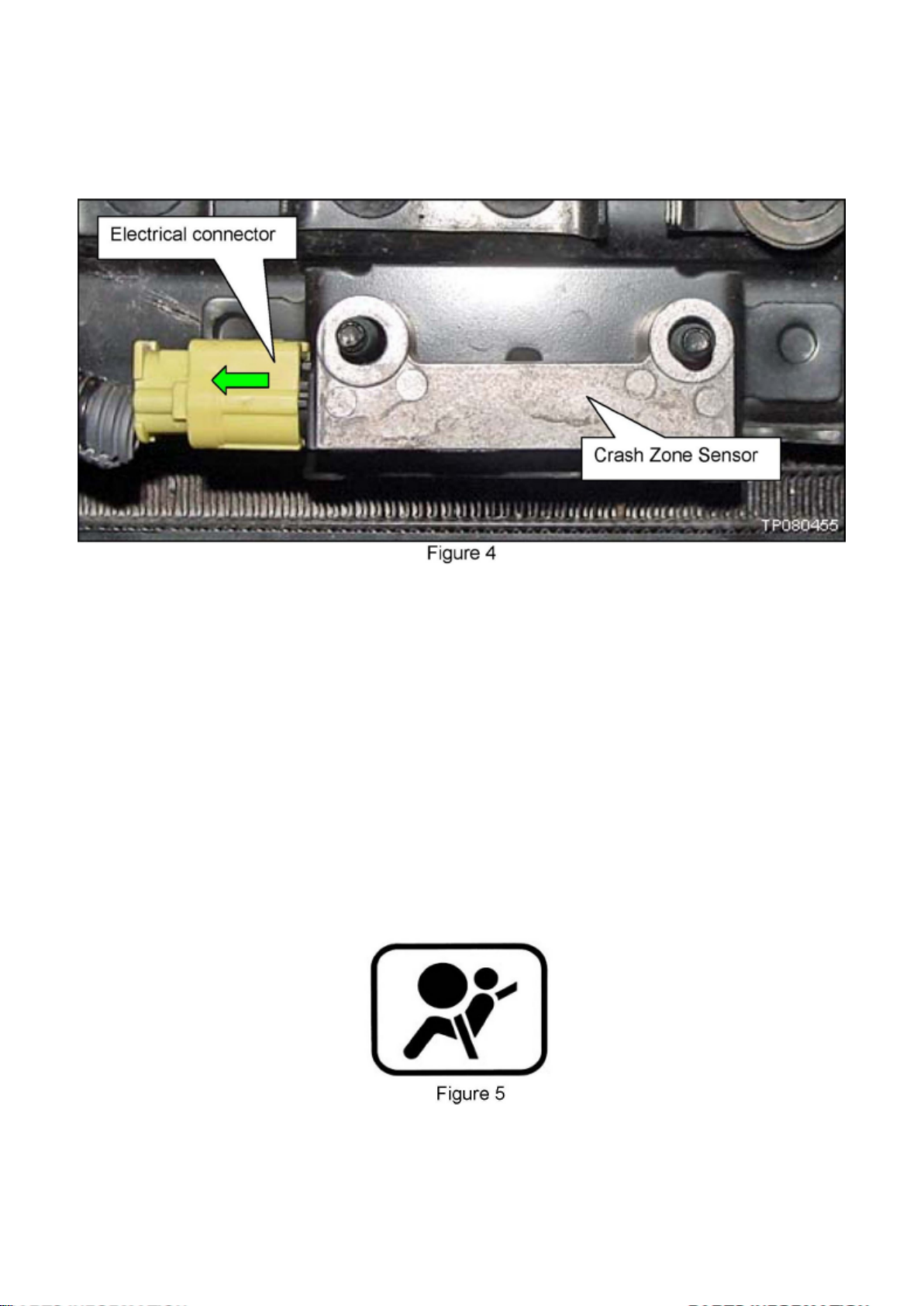
11. Disconnect the electrical connector shown in Figure 4.
Page 79

12. Remove the old Crash Zone Sensor.
13. Install the new Crash Zone Sensor in reverse order.
^ Reuse the original cover.
^ Make sure to use the new nuts included with the new sensor.
^ Torque nuts to 10.8 N.m (1.1 kg-m, 96 in-lb).
14. If DTC B1033, B1034, or B1035 was stored in the Air Bag control unit, use C-III to erase the
codes:
^ Make sure to erase DTCs in current SELF DIAG RESULTS, and, under Special function,
SELF-DIAG [PAST].
15. Check the Air Bag warning light as follows:
a. Sit in the driver seat and watch the air bag warning light as you turn the ignition ON (see Figure
5).
b. The air bag warning light should turn ON for 5 - 7 seconds, and then go OFF.
c. If the air bag warning light does not turn ON at all, does not turn OFF, or blinks, refer to the
Service Manual for diagnosis and repair.
^ Diagnosis and repair beyond replacement of the Crash Zone Sensor is not covered by this
bulletin.
16. Make the old Crash Zone Sensor unusable by breaking its electrical connector.
Page 80
Page 1113
Page 81

Page 9083
Page 82
How to Check Terminal
Page 83

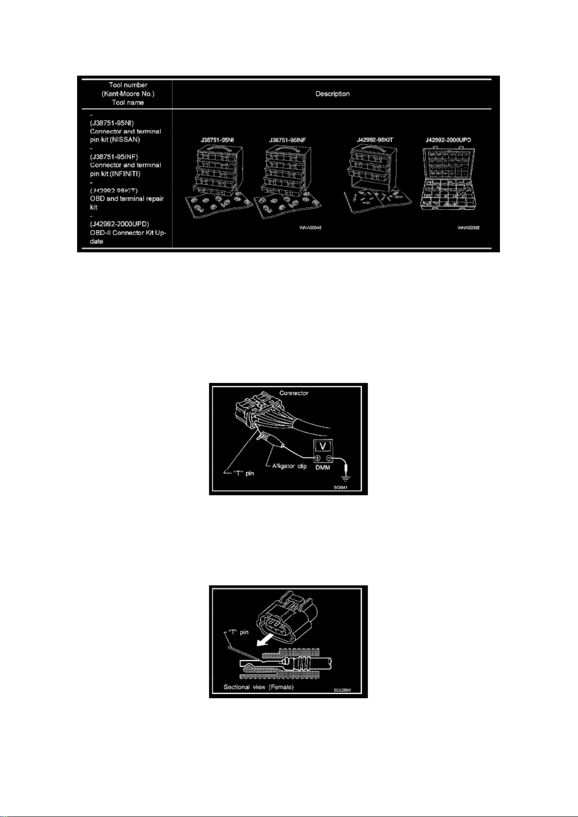
CONNECTOR AND TERMINAL PIN KIT
Use the connector and terminal pin kits listed below when replacing connectors or terminals. The
connector and terminal pin kits contain some of the most commonly used NISSAN/INFINITI
connectors and terminals. For detailed connector and terminal pin replacement procedures, refer to
the latest NISSAN/ INFINITI CONNECTOR AND TERMINAL PIN SERVICE MANUAL.
HOW TO PROBE CONNECTORS
Connector damage and an intermittent connection can result from improperly probing of the
connector during circuit checks. The probe of a digital multimeter (DMM) may not correctly fit the
connector cavity. To correctly probe the connector, follow the procedures below using a "T" pin. For
the best contact grasp the "T" pin using an alligator clip.
Probing from Harness Side
Standard type (not waterproof type) connector should be probed from harness side with "T" pin.
- If the connector has a rear cover such as a ECM connector, remove the rear cover before probing
the terminal.
- Do not probe waterproof connector from harness side. Damage to the seal between wire and
connector may result.
Probing from Terminal Side
Page 84
Page 13120
Body Control Module: Description and Operation
BCM (BODY CONTROL MODULE)
System Description
- BCM (body control module) controls the operation of various electrical units installed on the
vehicle.
BCM FUNCTION
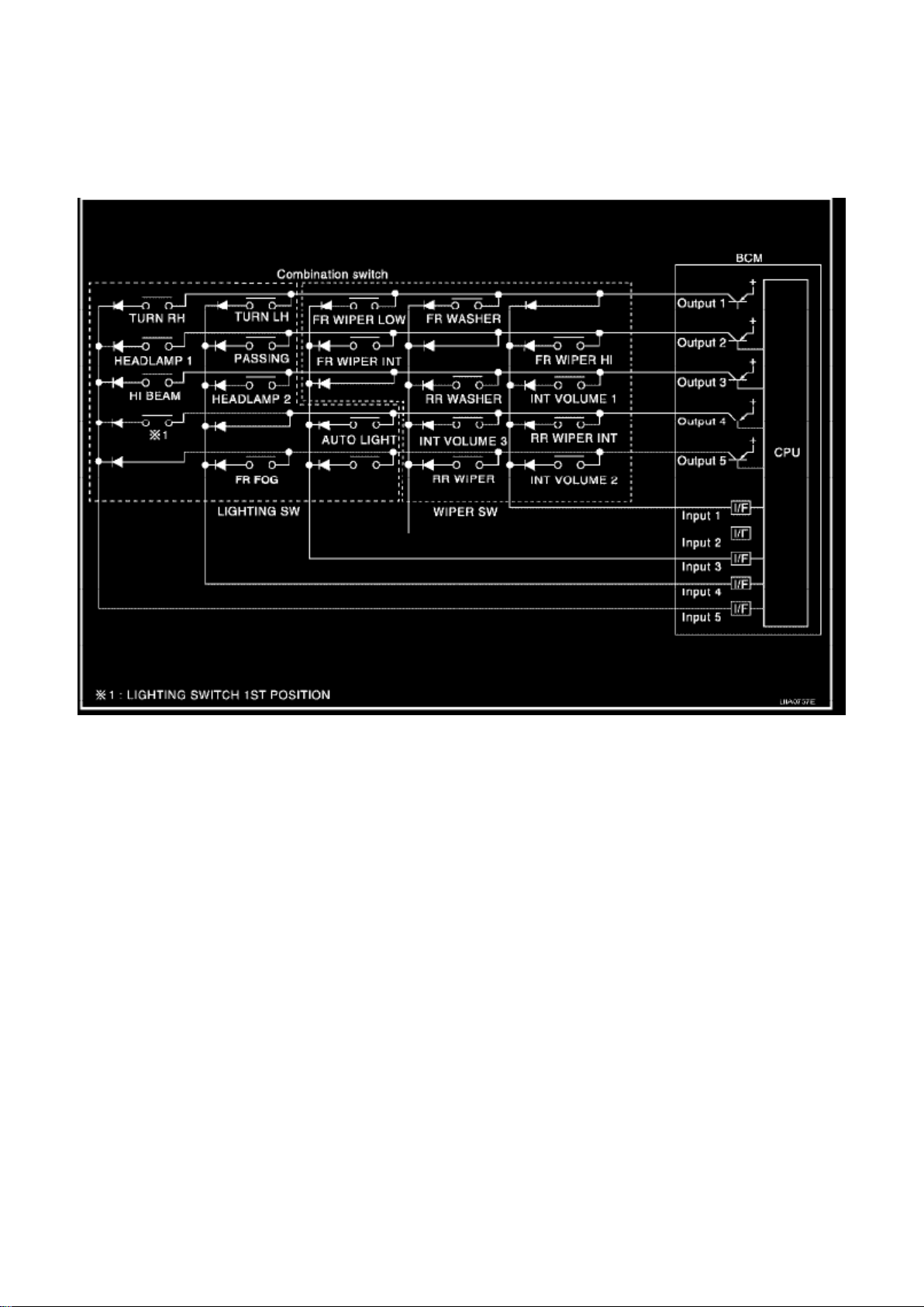
BCM has a combination switch reading function for reading the operation of combination switches
(light, wiper washer, turn signal) in addition to the function for controlling the operation of various
electrical components. Also, it functions as an interface that receives signals from the A/C control
unit, and sends signals to ECM using CAN communication.
COMBINATION SWITCH READING FUNCTION
1. Description
- BCM reads combination switch (light, wiper) status, and controls various electrical components
according to the results.
- BCM reads information of a maximum of 20 switches by combining five output terminals
(OUTPUT 1-5) and five input terminals (INPUT 1-5).
Page 85

2. Operation description
- BCM activates transistors of output terminals (OUTPUT 1-5) periodically and allows current to
flow in turn.
- If any (1 or more) of the switches are turned ON, circuit of output terminals (OUTPUT 1-5) and
input terminals (INPUT 1-5) becomes active.
- At this time, transistors of output terminals (OUTPUT 1-5) are activated to allow current to flow.
When voltage of input terminals (INPUT 1-5) corresponding to that switch changes, interface in
BCM detects voltage change and BCM determines that switch is ON.
Page 86

Page 911
Page 87
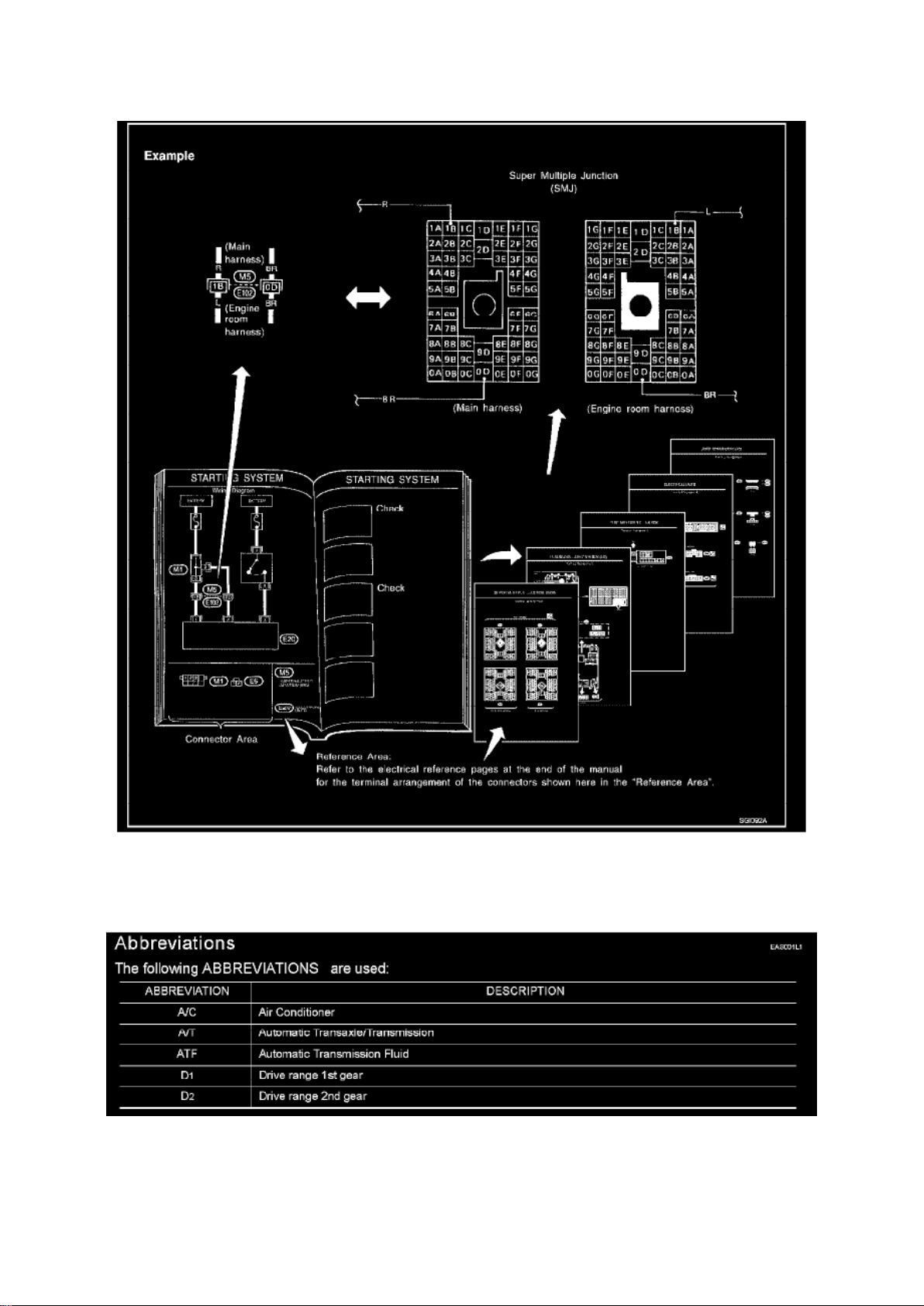
- The switch chart is used in schematic diagrams.
Page 88

- The switch diagram is used in wiring diagrams.
Reference Area
The Reference Area of the wiring diagram contains references to additional electrical reference
pages at the end of the manual. If connector numbers and titles are shown in the Reference Area
of the wiring diagram, these connector symbols are not shown in the Connector Area.
Page 89
Page 1957
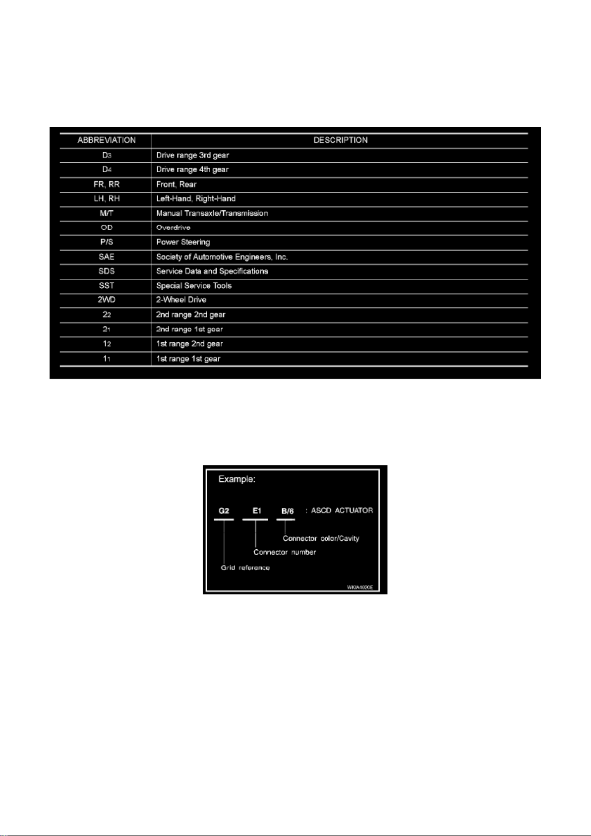
Abbreviations
How to Read Harness Layout
Harness Layout
HOW TO READ HARNESS LAYOUT
The following Harness Layouts use a map style grid to help locate connectors on the drawings:
- Main Harness
Page 90

- Engine Room Harness RH View (Engine Compartment), Generator Sub-harness, and Trailer Tow
Relay Sub-harness
- Engine Room Harness (Passenger Compartment)
- Engine Room Harness LH View (Engine Compartment)
- Engine Control Harness
- Chassis Harness
- Body Harness
- Body No. 2 Harness
- Room Lamp Harness
- Back Door Harness
- Back Door No. 2 Harness
- Rear Window Sub-Harness
- Rear Window Defogger Sub-Harness
To use the grid reference
1. Find the desired connector number on the connector list. 2. Find the grid reference. 3. On the
drawing, find the crossing of the grid reference letter column and number row. 4. Find the
connector number in the crossing zone. 5. Follow the line (if used) to the connector.
Page 91
Page 5739
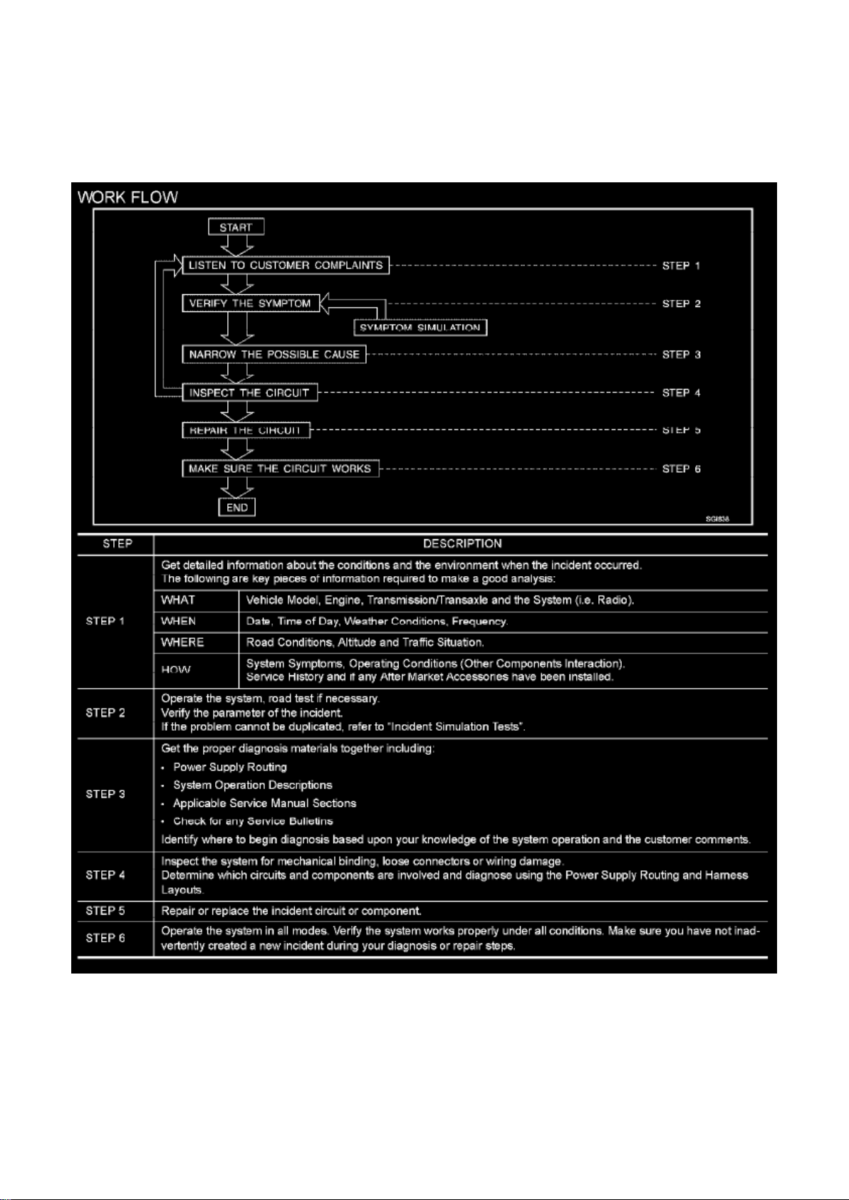
Work Flow
WORK FLOW
INCIDENT SIMULATION TESTS
Page 92

Introduction
Sometimes the symptom is not present when the vehicle is brought in for service. If possible,
re-create the conditions present at the time of the incident. Doing so may help avoid a No Trouble
Found Diagnosis. The following section illustrates ways to simulate the conditions/environment
under which the owner experiences an electrical incident.
The section is broken into the six following topics:
- Vehicle vibration
- Heat sensitive
- Freezing
- Water intrusion
- Electrical load
Page 93

Page 4523
Page 94
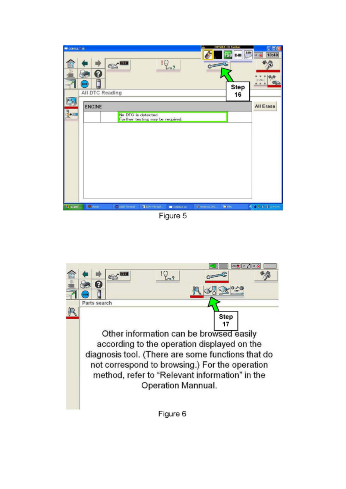
16. If there are no DTCs, select the "Repair" icon (see Figure 5).
Page 95

^ If there are any DTCs other than those listed in the accompanying Symptom based TSB,
diagnose, perform repairs, and erase DTCs before continuing.
17. Select the "ECM Reprogram" icon. (See Figure 6.)
Page 96

Upper Link
Page 97

Ball Joint: Service and Repair Upper Link
Page 98

INSPECTION AFTER REMOVAL
Upper Link Check for deformation and cracks. Replace if necessary.
Upper Link Ball Joint Check for distortion and damage. Replace if necessary
Page 99
Page 7568
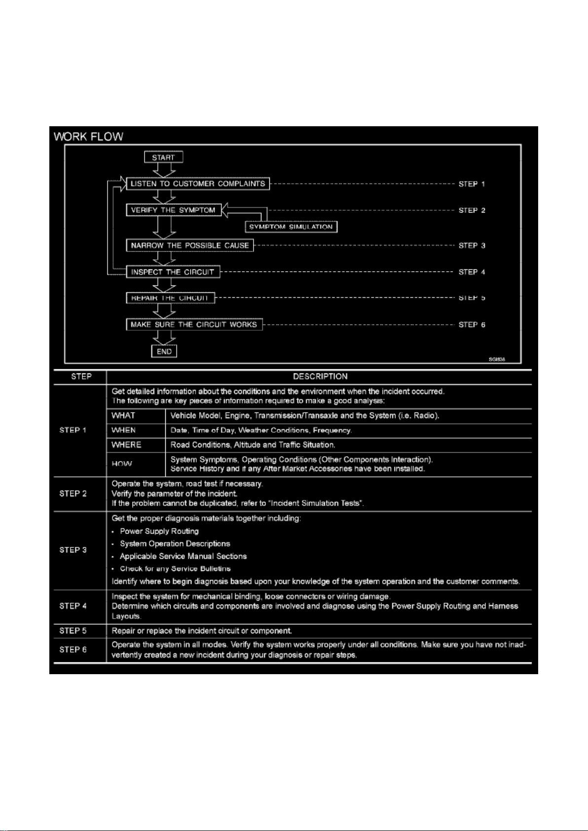
Work Flow
WORK FLOW
INCIDENT SIMULATION TESTS
Page 100

Introduction
Sometimes the symptom is not present when the vehicle is brought in for service. If possible,
re-create the conditions present at the time of the incident. Doing so may help avoid a No Trouble
Found Diagnosis. The following section illustrates ways to simulate the conditions/environment
under which the owner experiences an electrical incident.
The section is broken into the six following topics:
- Vehicle vibration
- Heat sensitive
- Freezing
- Water intrusion
- Electrical load
 Loading...