


ELECTRICAL SYSTEM
GI
MA
CONTENTS
PRECAUTIONS ...............................................................4
Supplemental Restraint System (SRS) ″AIR
BAG″ and ″SEAT BELT PRE-TENSIONER″...............4
Wiring Diagrams and Trouble Diagnosis.....................4
HARNESS CONNECTOR................................................5
Description...................................................................5
STANDARDIZED RELAY................................................7
Description...................................................................7
POWER SUPPLY ROUTING...........................................9
Schematic....................................................................9
Wiring Diagram - POWER - ......................................11
Inspection...................................................................19
GROUND........................................................................20
Ground Distribution....................................................20
COMBINATION SWITCH ..............................................32
Check.........................................................................32
Replacement..............................................................33
STEERING SWITCH......................................................34
Check.........................................................................34
HEADLAMP (FOR USA)...............................................35
System Description....................................................35
Wiring Diagram - H/LAMP -.......................................36
Trouble Diagnoses.....................................................37
Bulb Replacement .....................................................37
Aiming Adjustment.....................................................38
HEADLAMP (FOR CANADA) - DAYTIME LIGHT
SYSTEM - ......................................................................40
Component Parts and Harness Connector
Location .....................................................................40
System Description....................................................40
Schematic..................................................................43
Wiring Diagram - DTRL -...........................................44
Trouble Diagnoses.....................................................47
Bulb Replacement .....................................................48
Aiming Adjustment.....................................................48
PARKING, LICENSE AND TAIL LAMPS .....................49
Wiring Diagram - TAIL/L -..........................................49
STOP LAMP ..................................................................51
Wiring Diagram - STOP/L - .......................................51
SECTION
BACK-UP LAMP............................................................52
Wiring Diagram - BACK/L -.......................................52
FRONT FOG LAMP.......................................................53
System Description....................................................53
Wiring Diagram - F/FOG -.........................................54
Aiming Adjustment.....................................................55
TURN SIGNAL AND HAZARD WARNING LAMPS.....56
System Description....................................................56
Wiring Diagram - TURN -..........................................58
Trouble Diagnoses.....................................................60
Electrical Components Inspection.............................60
ILLUMINATION..............................................................61
System Description....................................................61
Wiring Diagram - ILL -...............................................62
INTERIOR, MAP, VANITY AND TRUNK ROOM
LAMPS...........................................................................64
System Description....................................................64
Wiring Diagram - INT/L -...........................................68
CONSULT-II Inspection Procedure (With Multi-
Remote Control System)...........................................73
CONSULT-II Application Items (With
Multi-Remote Control System) ..................................74
Trouble Diagnoses for Interior Lamp Timer (With
Power Door Locks and Without Multi-Remote
Control System).........................................................75
Trouble Diagnoses for Interior Lamp Timer (With
Multi-Remote Control System) ..................................80
METERS AND GAUGES...............................................85
Component Parts and Harness Connector
Location .....................................................................85
System Description....................................................86
Combination Meter ....................................................88
Schematic..................................................................90
Construction...............................................................92
Wiring Diagram - METER - .......................................93
Meter/Gauge Operation and Odo/Trip Meter
Segment Check in Diagnosis Mode..........................95
Trouble Diagnoses.....................................................96
Electrical Components Inspection...........................103
EL
EM
LC
EC
FE
CL
MT
AT
AX
SU
BR
ST
RS
BT
HA
SC
IDX

CONTENTS (Cont’d)
WARNING LAMPS......................................................105
Schematic................................................................105
Wiring Diagram - WARN -.......................................107
Electrical Components Inspection...........................114
WARNING CHIME.......................................................115
Component Parts and Harness Connector
Location ...................................................................115
System Description..................................................116
Wiring Diagram - CHIME - ......................................118
CONSULT-II Inspection Procedure (With Multi-
Remote Control System).........................................121
CONSULT-II Application Items (With
Multi-Remote Control System) ................................122
Trouble Diagnoses (Without Multi-Remote
Control System).......................................................123
Trouble Diagnoses (With Multi-Remote Control
System)....................................................................129
FRONT WIPER AND WASHER..................................137
System Description..................................................137
Wiring Diagram - WIPER -......................................139
Removal and Installation.........................................141
Washer Nozzle Adjustment .....................................142
Washer Tube Layout ...............................................142
HORN...........................................................................143
Wiring Diagram - HORN - .......................................143
CIGARETTE LIGHTER................................................144
Wiring Diagram - CIGAR -.......................................144
REAR WINDOW DEFOGGER.....................................145
Component Parts and Harness Connector
Location ...................................................................145
System Description..................................................146
Wiring Diagram - DEF -...........................................148
CONSULT-II Inspection Procedure (With Multi-
Remote Control System).........................................150
CONSULT-II Application Items (With
Multi-Remote Control System) ................................151
Trouble Diagnoses (Without Multi-Remote
Control System).......................................................151
Trouble Diagnoses (With Multi-Remote Control
System)....................................................................154
Electrical Components Inspection...........................158
Filament Check........................................................158
Filament Repair .......................................................159
AUDIO..........................................................................161
System Description..................................................161
Wiring Diagram - AUDIO -.......................................162
Trouble Diagnoses...................................................164
Inspection.................................................................164
Audio Unit Removal and Installation.......................165
Location of Antenna.................................................166
Removal and Installation of Antenna.......................166
POWER SUNROOF.....................................................167
System Description..................................................167
Wiring Diagram - SROOF -.....................................168
DOOR MIRROR...........................................................169
Wiring Diagram - MIRROR - ...................................169
HEATED MIRROR.......................................................170
Wiring Diagram - H/MIRR -.....................................170
TRUNK LID OPENER..................................................171
Wiring Diagram - TLID -..........................................171
AUTOMATIC SPEED CONTROL DEVICE (ASCD)...173
Component Parts and Harness Connector
Location ...................................................................173
System Description..................................................175
Schematic................................................................177
Wiring Diagram - ASCD - ........................................178
Fail-safe System......................................................182
Trouble Diagnoses...................................................183
Electrical Component Inspection.............................191
ASCD Wire Adjustment ...........................................192
POWER WINDOW.......................................................193
System Description..................................................193
Wiring Diagram - WINDOW -..................................195
Trouble Diagnoses...................................................197
POWER DOOR LOCK.................................................198
Component Parts and Harness Connector
Location ...................................................................198
System Description (Without Multi-Remote
Control System).......................................................199
System Description (With Multi-Remote Control
System)....................................................................199
Schematic................................................................200
Wiring Diagram - D/LOCK -.....................................202
CONSULT-II Inspection Procedure (With Multi-
Remote Control System).........................................211
CONSULT-II Application Items (With
Multi-Remote Control System) ................................212
Trouble Diagnoses (Without Multi-Remote
Control System).......................................................213
Trouble Diagnoses (With Multi-Remote Control
System)....................................................................219
MULTI-REMOTE CONTROL SYSTEM.......................229
Component Parts and Harness Connector
Location ...................................................................229
System Description..................................................230
Schematic................................................................233
Wiring Diagram - MULTI - .......................................234
CONSULT-II Inspection Procedure..........................237
CONSULT-II Application Items ................................238
Trouble Diagnoses...................................................239
ID Code Entry Procedure........................................254
Remote Controller Battery Replacement.................258
THEFT WARNING SYSTEM.......................................259
EL-2

CONTENTS (Cont’d)
Component Parts and Harness Connector
Location ...................................................................259
System Description..................................................261
Schematic................................................................264
Wiring Diagram - THEFT -.......................................265
CONSULT-II Inspection Procedure..........................269
CONSULT-II Application Item..................................270
Trouble Diagnoses...................................................271
Electrical Components Inspection...........................290
SMART ENTRANCE CONTROL UNIT.......................291
Description...............................................................291
CONSULT-II.............................................................293
Schematic................................................................295
Smart Entrance Control Unit Inspection Table........297
TIME CONTROL UNIT ................................................298
Description (Without Power Door Locks)................298
Schematic (Without Power Door Locks) .................299
Time Control Unit Inspection Table (Without
Power Door Locks)..................................................300
Description (With Power Door Locks).....................301
Schematic (With Power Door Locks) ......................302
Time Control Unit Inspection Table (With Power
Door Locks) .............................................................304
NVIS (NISSAN VEHICLE IMMOBILIZER SYSTEM
- NATS) ........................................................................305
Component Parts and Harness Connector
Location ...................................................................305
System Description..................................................306
System Composition................................................306
Wiring Diagram - NATS -.........................................307
CONSULT-II.............................................................308
Trouble Diagnoses...................................................311
How to Replace NVIS (NATS) IMMU......................324
ELECTRICAL UNITS LOCATION...............................325
Engine Compartment...............................................325
Passenger Compartment.........................................326
HARNESS LAYOUT....................................................328
How to Read Harness Layout.................................328
Outline......................................................................329
Main Harness...........................................................330
Engine Room Harness ............................................332
Engine Control Harness ..........................................335
Body Harness..........................................................341
Room Lamp Harness...............................................343
Front Door Harness.................................................344
Rear Door Harness..................................................346
BULB SPECIFICATIONS............................................348
Headlamp.................................................................348
Exterior Lamp ..........................................................348
Interior Lamp............................................................348
WIRING DIAGRAM CODES (CELL CODES).............349
GI
MA
EM
LC
EC
FE
CL
MT
AT
AX
SU
BR
ST
RS
BT
HA
SC
IDX
EL-3

PRECAUTIONS
Supplemental Restraint System (SRS) “AIR BAG” and “SEAT BELT PRE-TENSIONER”
Supplemental Restraint System (SRS) “AIR
BAG” and “SEAT BELT PRE-TENSIONER”
The Supplemental Restraint System such as “AIR BAG” and “SEAT BELTPRE-TENSIONER” used along with
a seat belt, helps to reduce the risk or severity of injury to the driver and front passenger for certain types of
collision. The SRS system composition which is available to NISSAN MODEL B15 is as follows:
쐌 For a frontal collision
The Supplemental Restraint System consists of driver air bag module (located in the center of the steering wheel), front passenger air bag module (located on the instrument panel on passenger side), front seat
belt pre-tensioners, a diagnosis sensor unit, warning lamp, wiring harness and spiral cable.
쐌 For a side collision
The Supplemental Restraint System consists of front side air bag module (located in the outer side of front
seat), side air bag (satellite) sensor, diagnosis sensor unit (one of components of air bags for a frontal
collision), wiring harness, warning lamp (one of components of air bags for a frontal collision).
Information necessary to service the system safely is included in the RS section of this Service Manual.
WARNING:
쐌 To avoid rendering the SRS inoperative, which could increase the risk of personal injury or death
in the event of a collision which would result in air bag inflation, all maintenance should be performed by an authorized NISSAN dealer.
쐌 Improper maintenance, including incorrect removal and installation of the SRS, can lead to per-
sonal injury caused by unintentional activation of the system. For removal of Spiral Cable and Air
Bag Module, see the RS section.
쐌 Do not use electrical test equipment on any circuit related to the SRS unless instructed to in this
Service Manual. Spiral cable and wiring harnesses covered with yellow insulation tape either just
before the harness connectors or for the complete harness are related to the SRS.
NIEL0001
Wiring Diagrams and Trouble Diagnosis
When you read wiring diagrams, refer to the following:
쐌 GI-11, “HOW TO READ WIRING DIAGRAMS”
쐌 “POWER SUPPLY ROUTING”, EL-9 for power distribution circuit
When you perform trouble diagnosis, refer to the following:
쐌 GI-36, “How to Follow Test Groups in Trouble Diagnoses”
쐌 GI-25, “HOW TO PERFORM EFFICIENT DIAGNOSIS FOR AN ELECTRICAL INCIDENT”
Check for any Service bulletins before servicing the vehicle.
NIEL0002
EL-4

HARNESS CONNECTOR
Description
Description
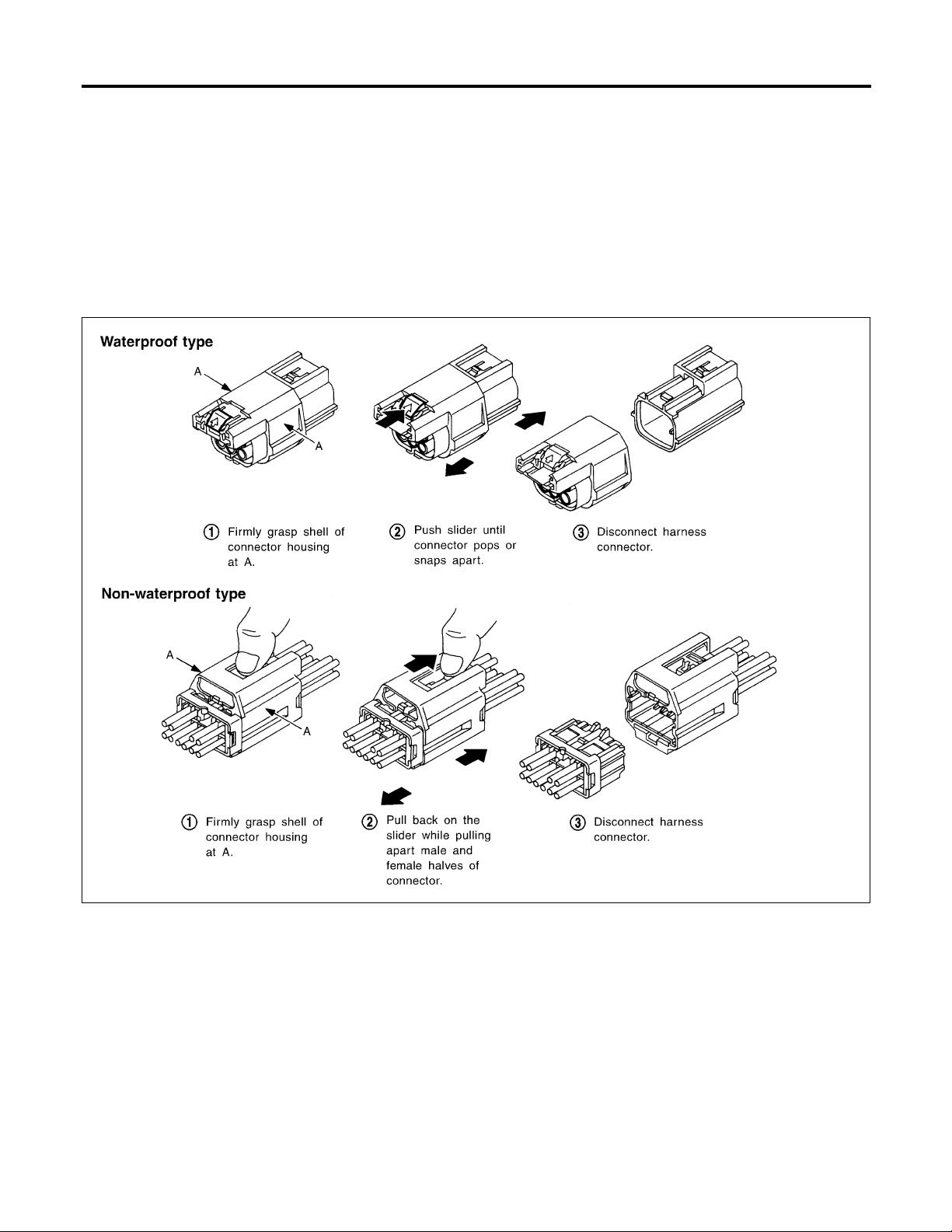
HARNESS CONNECTOR (TAB-LOCKING TYPE)
쐌 The tab-locking type connectors help prevent accidental looseness or disconnection.
쐌 The tab-locking type connectors are disconnected by pushing or lifting the locking tab(s). Refer to the
illustration below.
Refer to the next page for description of the slide-locking type connector.
CAUTION:
Do not pull the harness or wires when disconnecting the connector.
[Example]
NIEL0003
NIEL0003S01
GI
MA
EM
LC
EC
FE
CL
MT
AT
AX
SU
BR
ST
RS
BT
HA
SC
EL-5
SEL769DA
IDX
Description (Cont’d)
HARNESS CONNECTOR
HARNESS CONNECTOR (SLIDE-LOCKING TYPE)
=NIEL0003S02
쐌 A new style slide-locking type connector is used on certain systems and components, especially those
related to OBD.
쐌 The slide-locking type connectors help prevent incomplete locking and accidental looseness or disconnec-
tion.
쐌 The slide-locking type connectors are disconnected by pushing or pulling the slider. Refer to the illustra-
tion below.
CAUTION:
쐌 Do not pull the harness or wires when disconnecting the connector.
쐌 Be careful not to damage the connector support bracket when disconnecting the connector.
[Example]
EL-6
AEL299C
STANDARDIZED RELAY
Description
Description
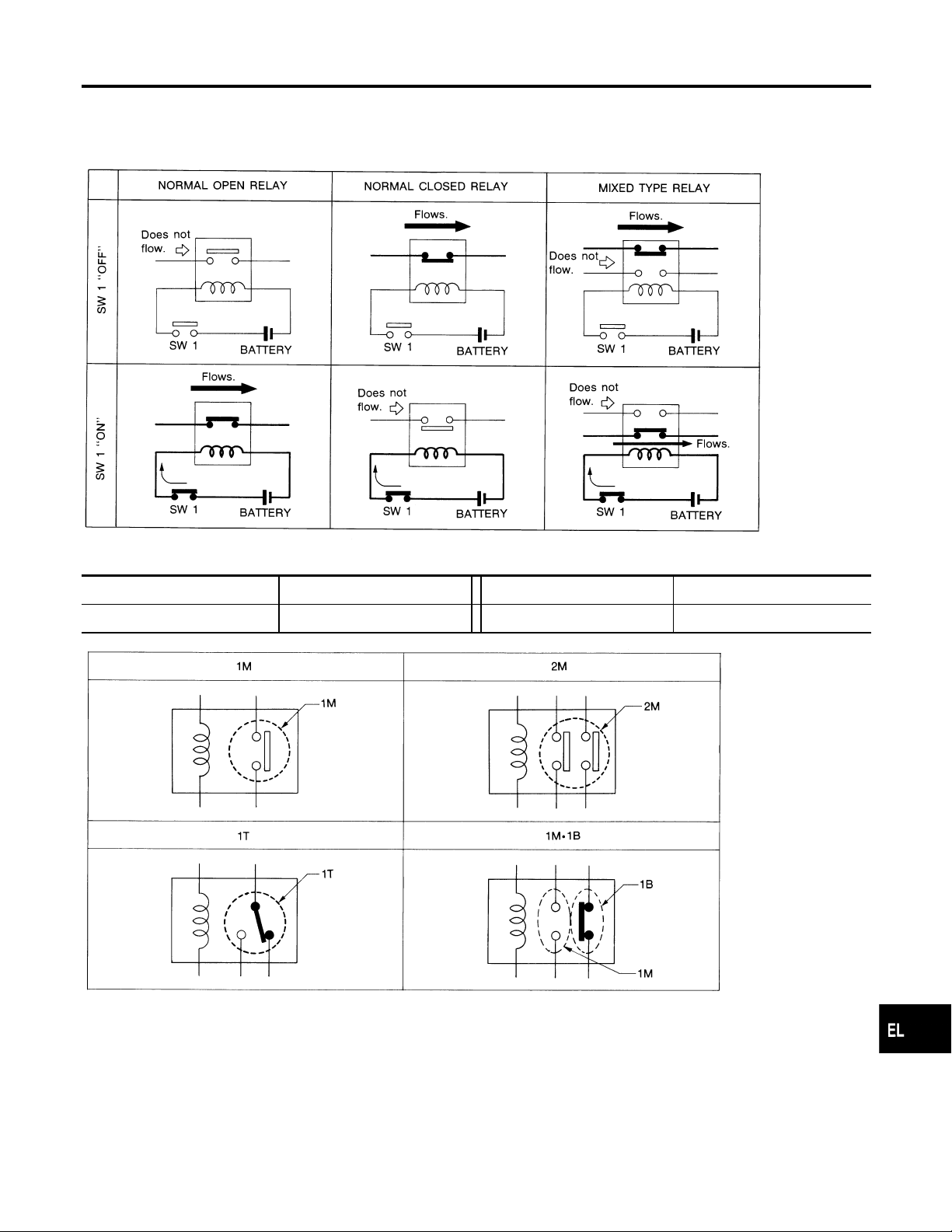
NORMAL OPEN, NORMAL CLOSED AND MIXED TYPE RELAYS
Relays can mainly be divided into three types: normal open, normal closed and mixed type relays.
NIEL0004
NIEL0004S01
SEL881H
GI
MA
EM
LC
EC
FE
CL
MT
TYPE OF STANDARDIZED RELAYS
1M 1 Make 2M 2 Make
1T 1 Transfer 1M·1B 1 Make 1 Break
NIEL0004S02
SEL882H
AT
AX
SU
BR
ST
RS
BT
HA
SC
EL-7
IDX

Description (Cont’d)
STANDARDIZED RELAY
EL-8
LEL638

POWER SUPPLY ROUTING
Schematic
Schematic
For detailed ground distribution information, refer to “Ground Distribution”, EL-20.
NIEL0005
GI
MA
EM
LC
EC
FE
CL
MT
AT
AX
SU
BR
ST
RS
BT
HA
SC
EL-9
IDX
LEL407

Schematic (Cont’d)
POWER SUPPLY ROUTING
EL-10
WEL812
POWER SUPPLY ROUTING
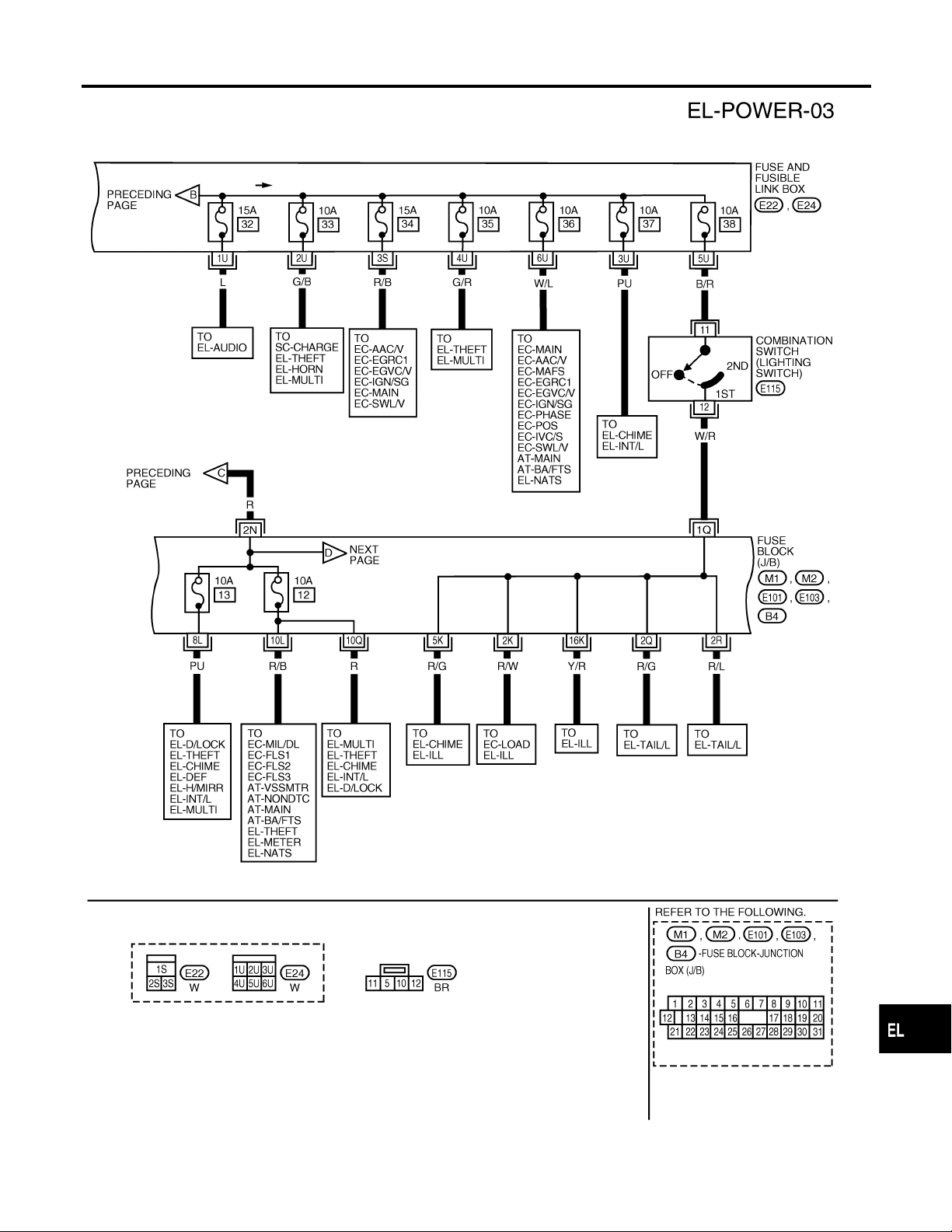
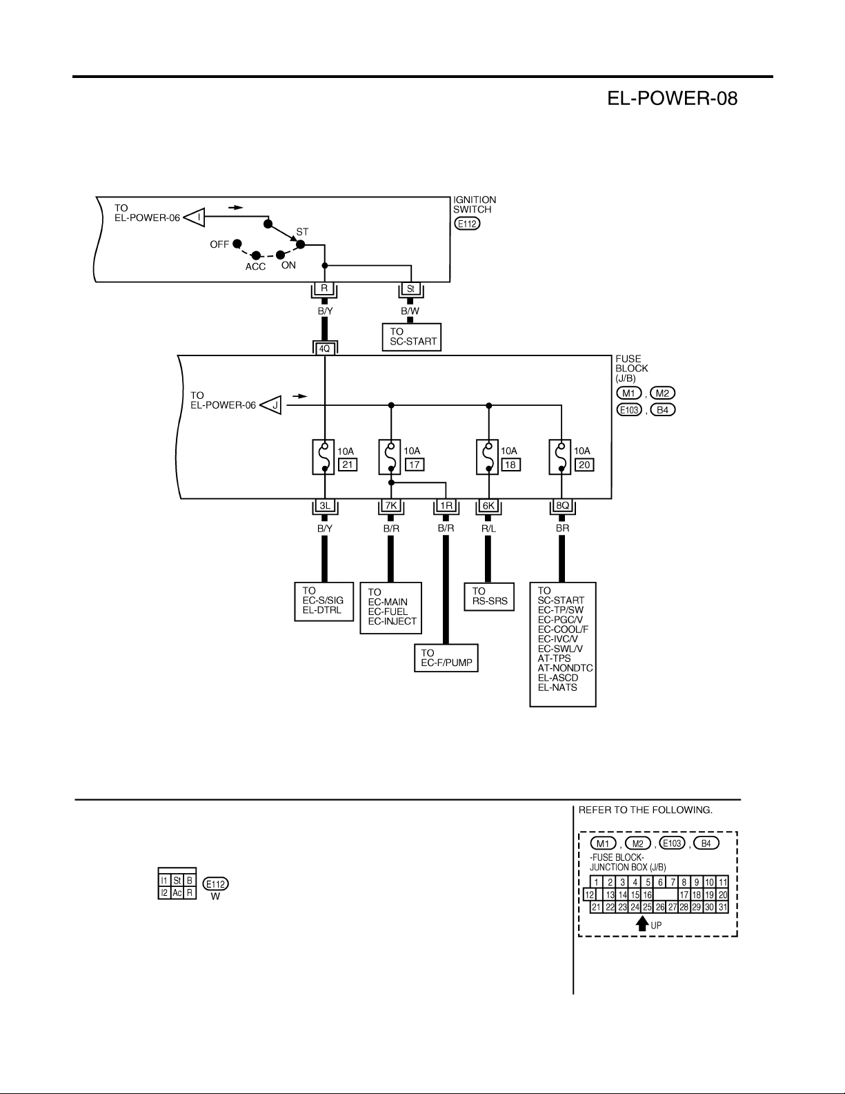
Wiring Diagram — POWER —
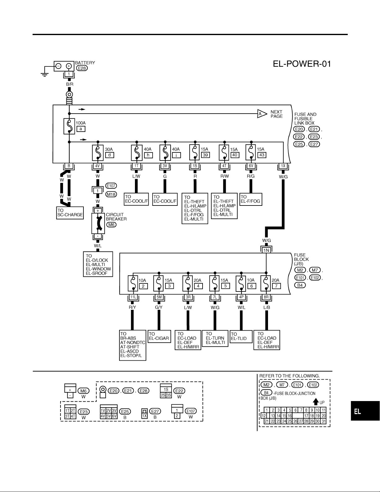
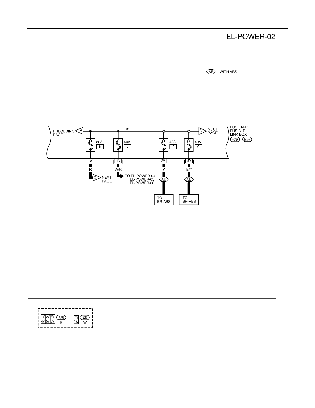
Wiring Diagram — POWER —
BATTERY POWER SUPPLY — IGNITION SW. IN ANY POSITION
NIEL0006
NIEL0006S01
GI
MA
EM
LC
EC
FE
CL
MT
AT
AX
SU
BR
ST
RS
BT
HA
SC
EL-11
LEL409
IDX
Wiring Diagram — POWER — (Cont’d)
POWER SUPPLY ROUTING
EL-12
LEL410
POWER SUPPLY ROUTING
Wiring Diagram — POWER — (Cont’d)
GI
MA
EM
LC
EC
FE
CL
MT
AT
AX
SU
BR
ST
RS
BT
HA
EL-13
SC
IDX
LEL411
Wiring Diagram — POWER — (Cont’d)
POWER SUPPLY ROUTING
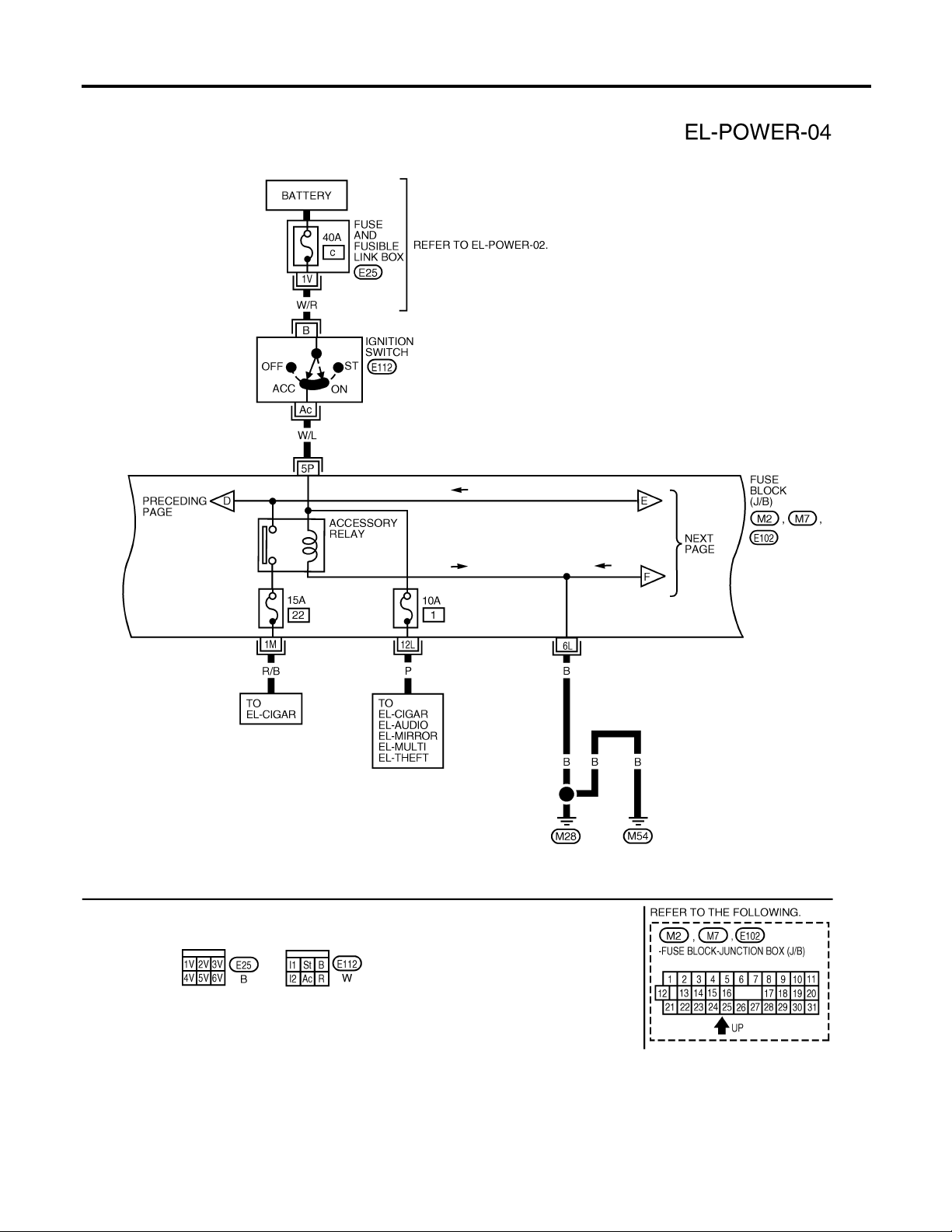
ACCESSORY POWER SUPPLY — IGNITION SW. IN “ACC” OR “ON”
NIEL0006S02
EL-14
LEL412

POWER SUPPLY ROUTING
Wiring Diagram — POWER — (Cont’d)
IGNITION POWER SUPPLY — IGNITION SW. IN “ON”
NIEL0006S04
GI
MA
EM
LC
EC
FE
CL
MT
AT
AX
SU
BR
ST
RS
BT
HA
SC
EL-15
LEL413
IDX
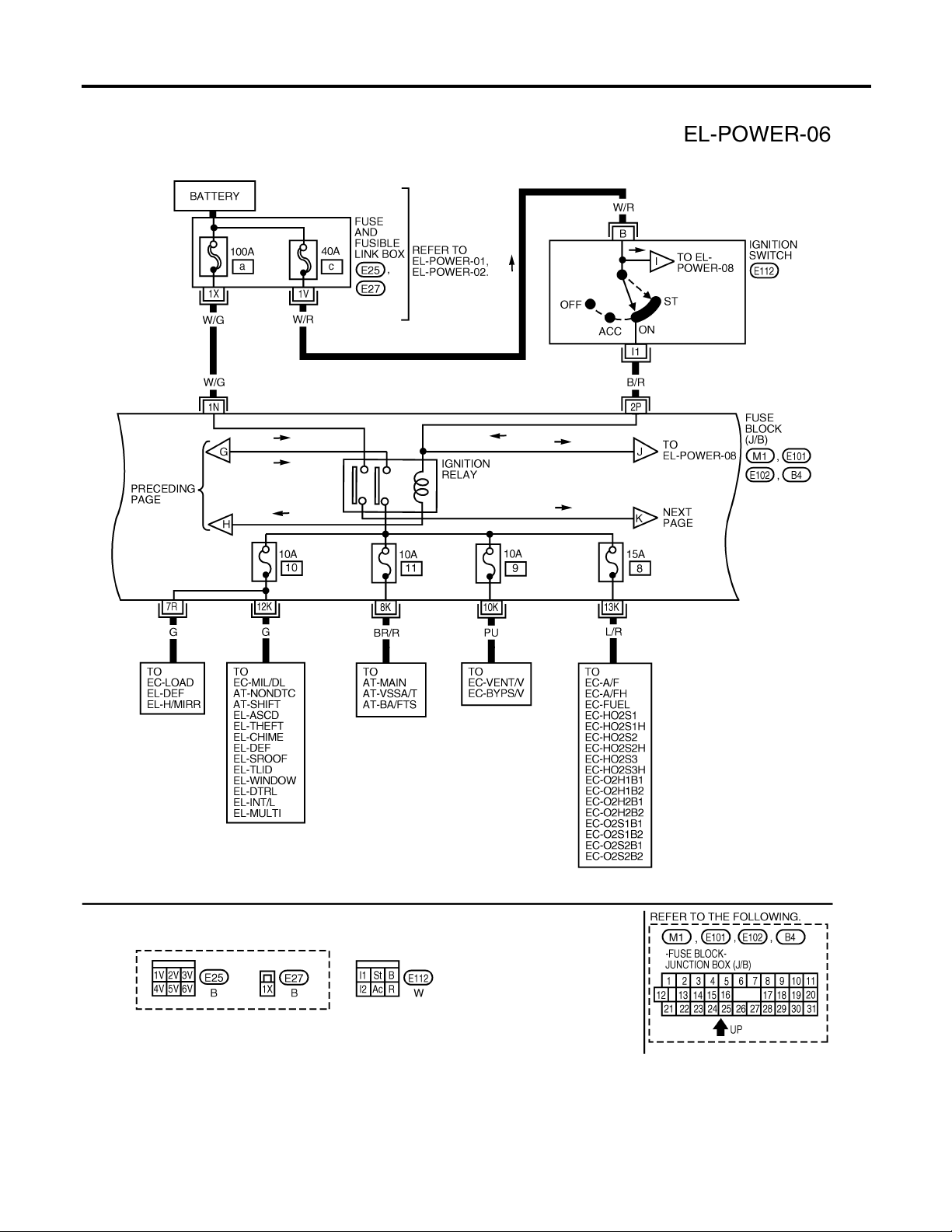
Wiring Diagram — POWER — (Cont’d)
POWER SUPPLY ROUTING
IGNITION POWER SUPPLY — IGNITION SW. IN “ON” AND/OR “START”
NIEL0006S03
EL-16
WEL813
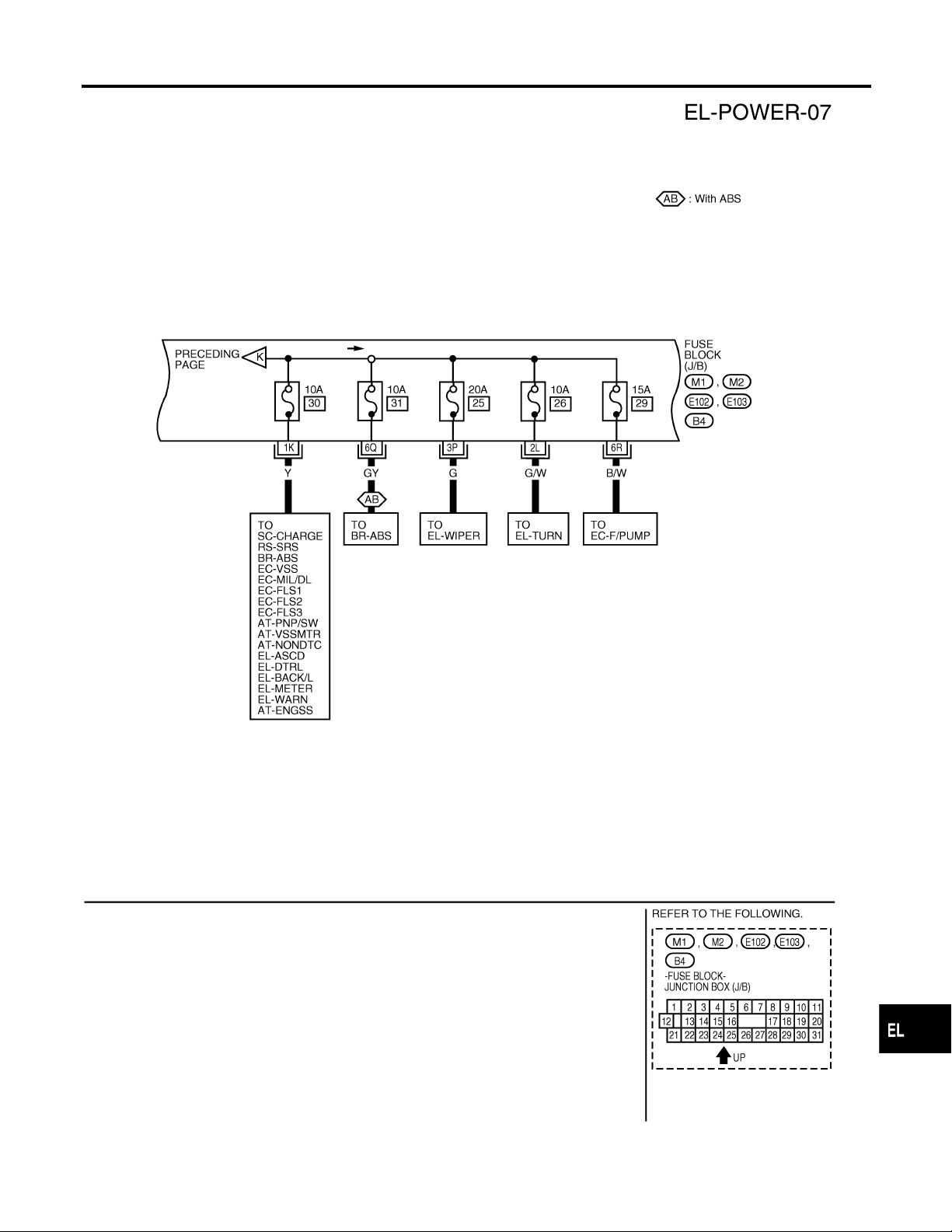
POWER SUPPLY ROUTING
Wiring Diagram — POWER — (Cont’d)
GI
MA
EM
LC
EC
FE
CL
MT
AT
AX
SU
BR
ST
RS
BT
HA
EL-17
SC
IDX
LEL415
Wiring Diagram — POWER — (Cont’d)
POWER SUPPLY ROUTING
EL-18
LEL416
POWER SUPPLY ROUTING
Inspection
CEL083
LEL639
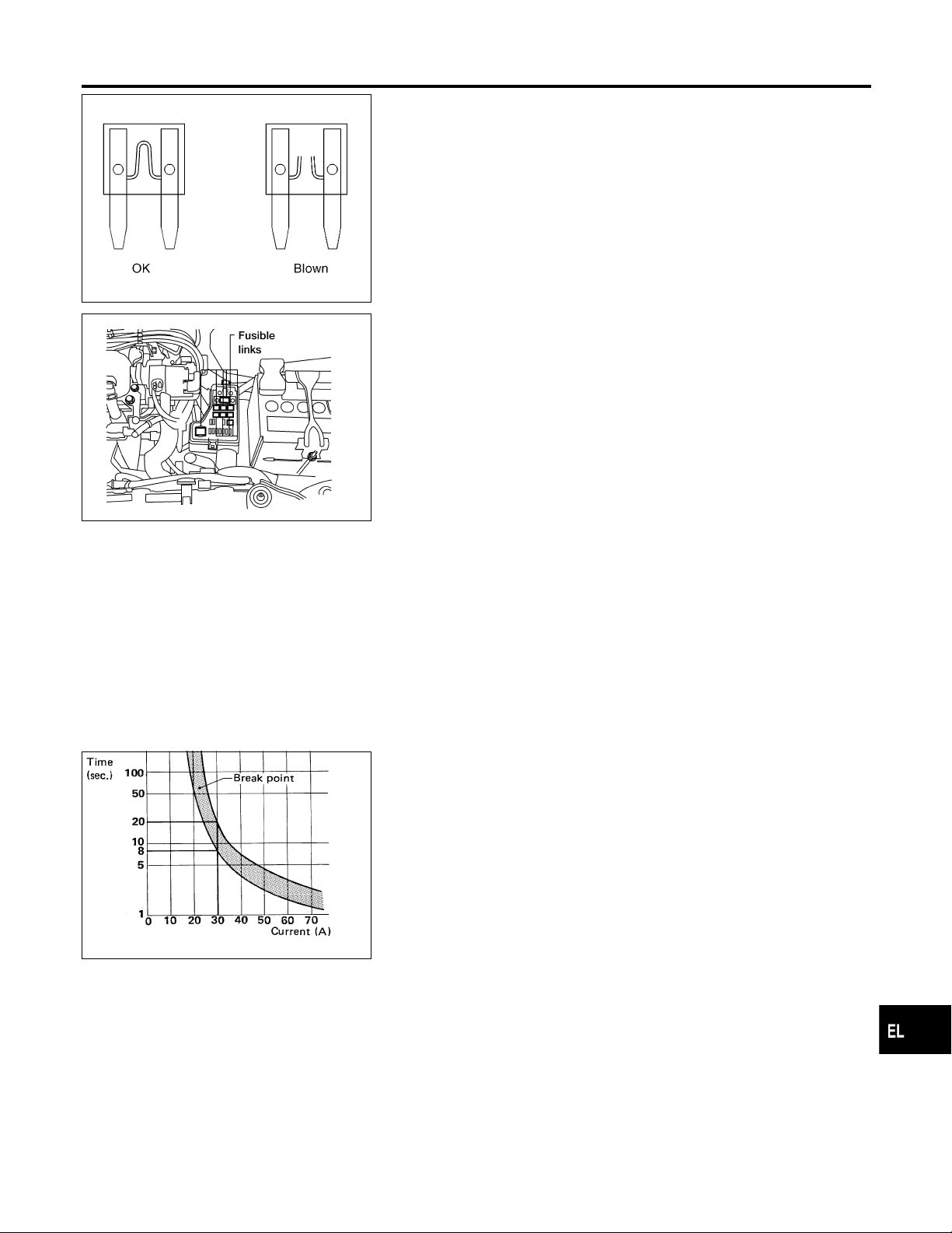
Inspection
FUSE
쐌 If fuse is blown, be sure to eliminate cause of problem
before installing new fuse.
쐌 Use fuse of specified rating. Never use fuse of more than
specified rating.
쐌 Do not partially install fuse; always insert it into fuse
holder properly.
쐌 Remove fuse for “ELECTRICAL PARTS (BAT)” if vehicle is
not used for a long period of time.
FUSIBLE LINK
A melted fusible link can be detected either by visual inspection or
by feeling with fingertip. If its condition is questionable, use circuit
tester or test lamp.
CAUTION:
쐌 If fusible link should melt, it is possible that critical circuit
(power supply or large current carrying circuit) is shorted.
In such a case, carefully check and eliminate cause of
problem.
쐌 Never wrap outside of fusible link with vinyl tape. Impor-
tant: Never let fusible link touch any other wiring harness,
vinyl or rubber parts.
NIEL0007
NIEL0007S01
NIEL0007S02
GI
MA
EM
LC
EC
FE
CL
MT
SBF284E
CIRCUIT BREAKER
For example, when current is 30A, the circuit is broken within 8 to
20 seconds.
A circuit breaker is used for the following systems:
쐌 Power door locks
쐌 Power sunroof
쐌 Power windows
쐌 Multi-remote control system
NIEL0007S03
AT
AX
SU
BR
ST
RS
BT
HA
SC
EL-19
IDX
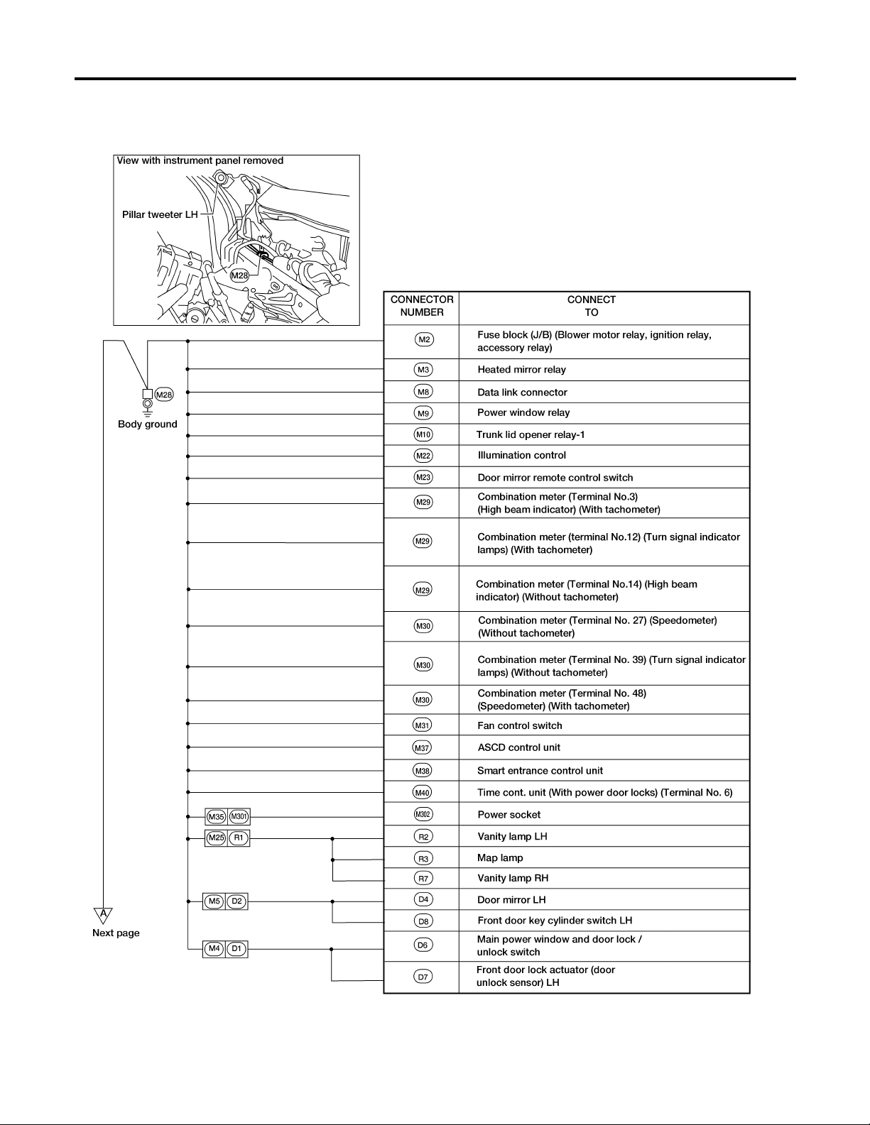
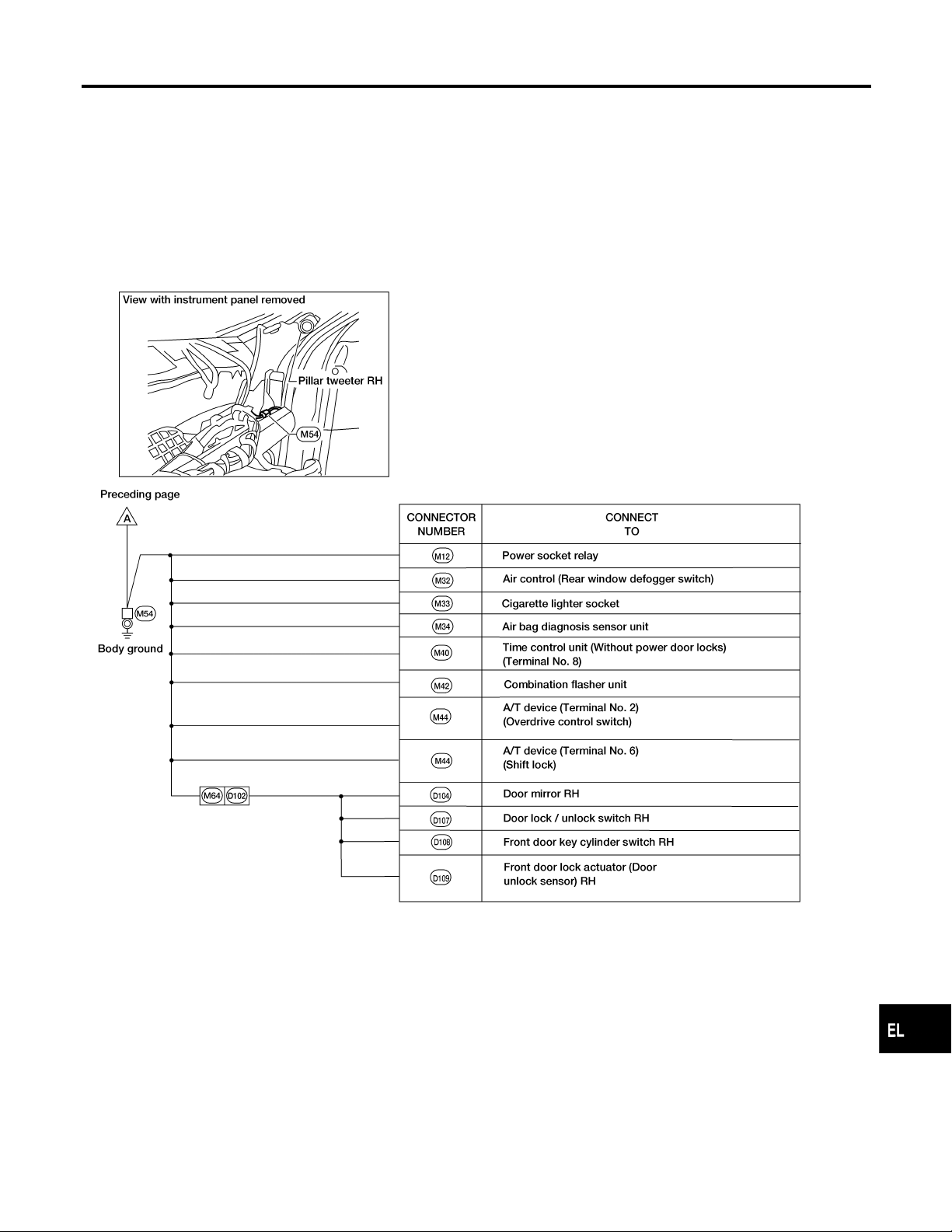
Ground Distribution
GROUND
MAIN HARNESS
Ground Distribution
NIEL0008
NIEL0008S01
EL-20
LEL424
GROUND
Ground Distribution (Cont’d)
GI
MA
EM
LC
EC
FE
CL
MT
AT
AX
SU
BR
ST
RS
BT
HA
EL-21
SC
IDX
LEL423

Ground Distribution (Cont’d)
GROUND
ENGINE ROOM HARNESS
NIEL0008S02
EL-22
LEL425

GROUND
Ground Distribution (Cont’d)
GI
MA
EM
LC
EC
FE
CL
MT
AT
AX
SU
BR
ST
RS
BT
HA
EL-23
SC
IDX
LEL426

Ground Distribution (Cont’d)
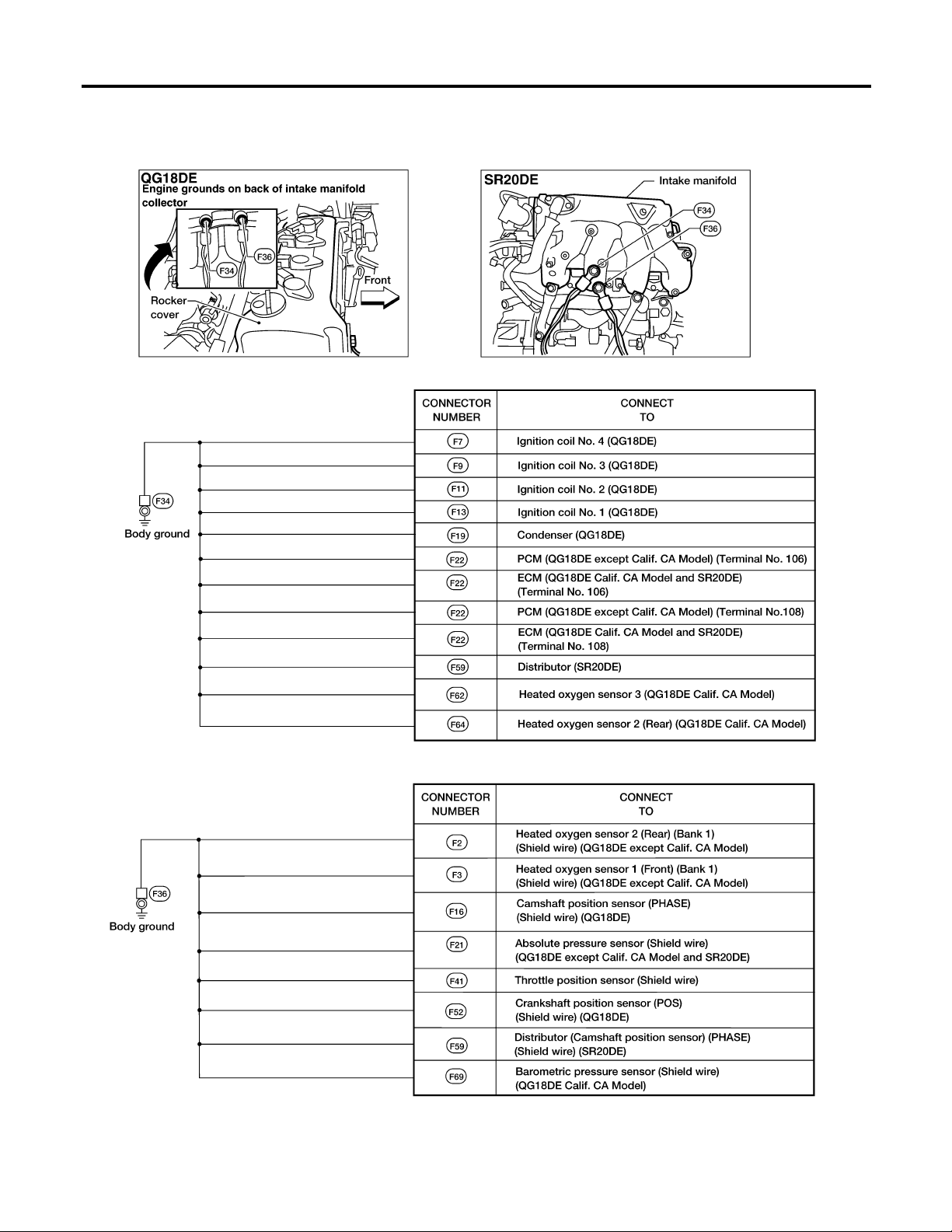
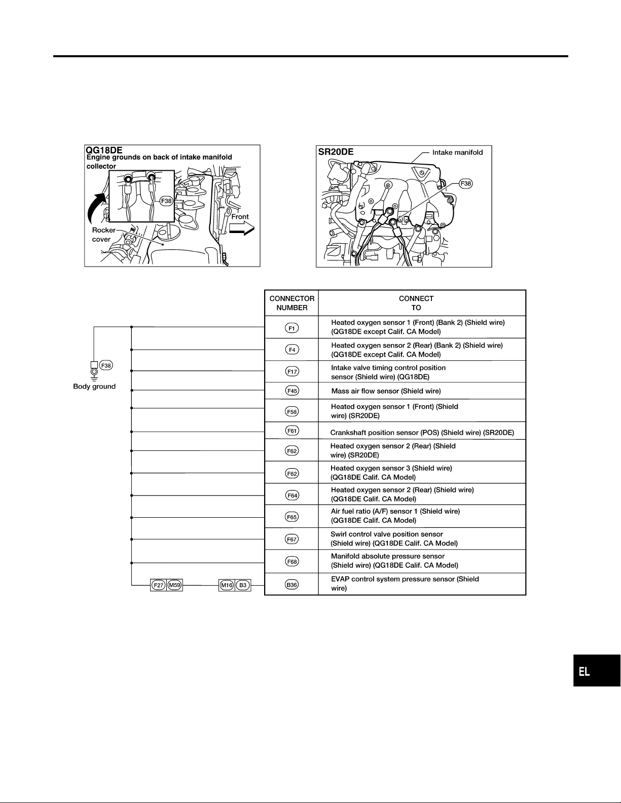
GROUND
ENGINE CONTROL HARNESS
NIEL0008S03
EL-24
LEL429

GROUND
Ground Distribution (Cont’d)
GI
MA
EM
LC
EC
FE
CL
MT
AT
AX
SU
BR
ST
RS
BT
HA
EL-25
SC
IDX
WEL555A
Ground Distribution (Cont’d)
GROUND
EL-26
WEL556A
GROUND
Ground Distribution (Cont’d)
GI
MA
EM
LC
EC
FE
CL
MT
AT
AX
SU
BR
ST
RS
BT
HA
EL-27
SC
IDX
WEL557A

Ground Distribution (Cont’d)
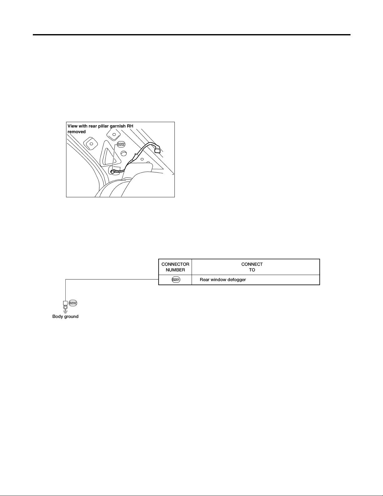
GROUND
BODY HARNESS
NIEL0008S04
EL-28
LEL427

GROUND
Ground Distribution (Cont’d)
GI
MA
EM
LC
EC
FE
CL
MT
AT
AX
SU
BR
ST
RS
BT
HA
EL-29
SC
IDX
LEL428
Ground Distribution (Cont’d)
GROUND
BODY NO. 2 HARNESS
=NIEL0008S05
EL-30
LEL434
 Loading...