

Nissan Sentra Clutch CL 2000 Owner's Manual

CLUTCH
GI
MA
CONTENTS
PRECAUTIONS ...............................................................2
Precautions..................................................................2
PREPARATION ...............................................................3
Special Service Tools ..................................................3
Commercial Service Tools...........................................3
NOISE, VIBRATION AND HARSHNESS (NVH)
TROUBLESHOOTING.....................................................4
NVH Troubleshooting Chart.........................................4
CLUTCH SYSTEM...........................................................5
Components.................................................................5
Inspection and Adjustment ..........................................6
ADJUSTING CLUTCH PEDAL
BLEEDING PROCEDURE
CLUTCH MASTER CYLINDER.......................................8
Components.................................................................8
Removal.......................................................................8
Installation....................................................................9
Disassembly.................................................................9
Inspection.....................................................................9
Assembly .....................................................................9
OPERATING CYLINDER...............................................11
Components...............................................................11
Removal.....................................................................11
Disassembly...............................................................11
Inspection...................................................................12
....................................6
..........................................7
SECTION
Assembly ...................................................................12
Installation..................................................................12
PIPING ...........................................................................13
Removal.....................................................................13
Installation..................................................................13
CLUTCH RELEASE MECHANISM...............................14
Components...............................................................14
Removal.....................................................................14
Inspection...................................................................14
Installation..................................................................14
CLUTCH DISC, CLUTCH COVER AND
FLYWHEEL....................................................................17
Components...............................................................17
Inspection and Adjustment ........................................17
CLUTCH DISC
CLUTCH COVER AND FLYWHEEL
FLYWHEEL INSPECTION
Installation..................................................................18
SERVICE DATA AND SPECIFICATIONS (SDS).........19
Clutch Control System...............................................19
Clutch Master Cylinder..............................................19
Clutch Operating Cylinder .........................................19
Clutch Disc.................................................................19
Clutch Cover..............................................................19
Clutch Pedal ..............................................................19
.........................................................17
CL
...........................18
........................................18
EM
LC
EC
FE
MT
AT
AX
SU
BR
ST
RS
BT
HA
SC
EL
IDX
Precautions
PRECAUTIONS
SBR686C
Precautions
NICL0001
쐌 Recommended fluid is brake fluid “DOT 3”.
쐌 Do not reuse drained brake fluid.
쐌 Be careful not to splash brake fluid on painted areas; it
may cause paint damage. If brake fluid is splashed on
painted areas, wash it away with water immediately.
쐌 Use flare nut wrench when removing or installing clutch
hydraulic tubes.
쐌 Use new brake fluid to clean or wash all parts of master
cylinder and operating cylinder.
쐌 Never use mineral oils such as gasoline or kerosene. It will
ruin the rubber parts of the hydraulic system.
WARNING:
After cleaning clutch disc, wipe it with a dust collector. Do not
use compressed air.
CL-2

PREPARATION
Special Service Tools
Special Service Tools
The actual shapes of Kent-Moore tools may differ from those of special service tools illustrated here.
Tool number
(Kent-Moore No.)
Tool name
KV30101600 (New)
KV30101000 (Former)
(J33213)
Clutch aligning bar
ST20050240
(—)
Diaphragm spring
adjusting wrench
KV32101000
(J25689-A)
Pin punch
Description
Installing clutch cover and clutch disc
a: 15.9 mm (0.626 in) dia.
b: 17.9 mm (0.705 in) dia.
c: 40 mm (1.57 in)
NT641
Adjusting unevenness of diaphragm spring of
clutch cover
a: 150 mm (5.91 in)
b: 25 mm (0.98 in)
NT404
Removing and installing spring pin
a: 4 mm (0.16 in) dia.
NICL0002
GI
MA
EM
LC
EC
FE
MT
AT
AX
NT410
Tool name Description
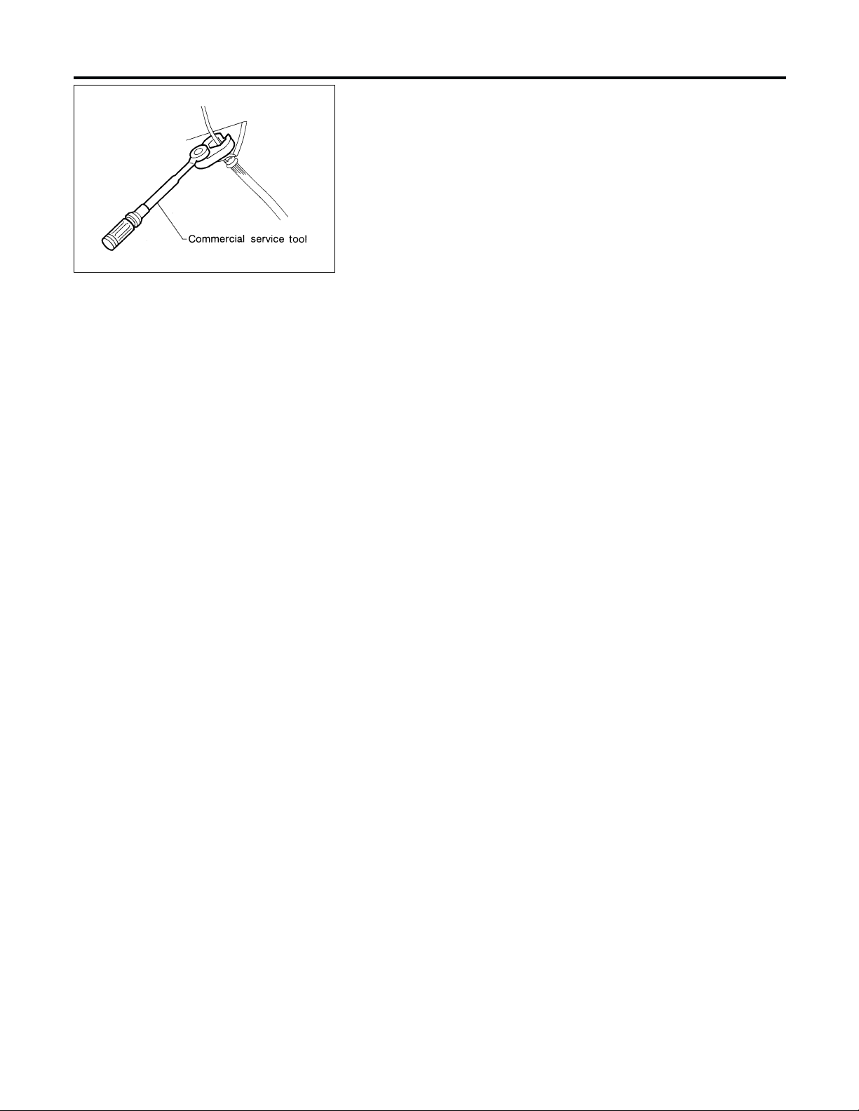
1 Flare nut crowfoot
2 Torque wrench
NT360
Commercial Service Tools
Removing and installing clutch piping
a: 10 mm (0.39 in)
SU
NICL0003
BR
ST
RS
BT
HA
SC
EL
IDX
CL-3
NOISE, VIBRATION AND HARSHNESS (NVH) TROUBLESHOOTING
NVH Troubleshooting Chart
NICL0004
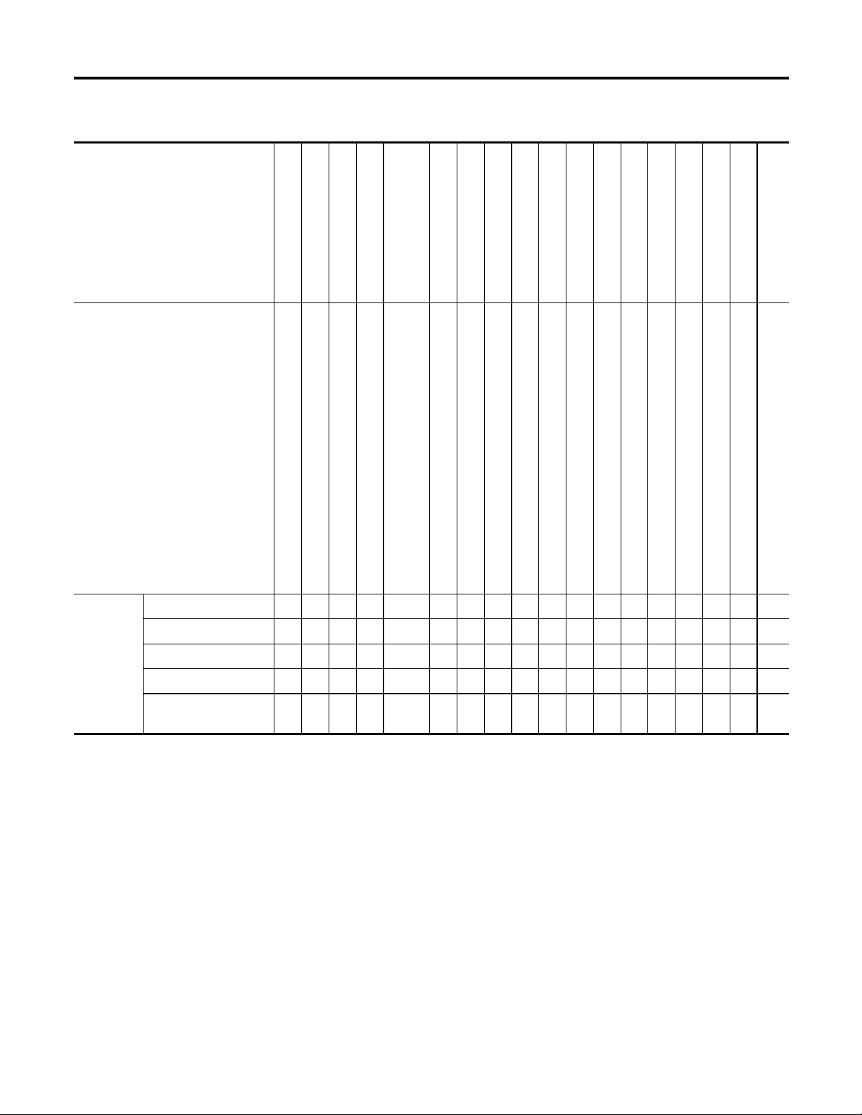
NVH Troubleshooting Chart
NICL0004S01
Use the chart below to help you find the cause of the symptom. The numbers indicate the order of inspection.
Check each part in order. If necessary, repair or replace these parts.
Reference page
SUSPECTED PARTS
(Possible cause)
CL-6
CL-7
CL-8
CL-11
CL-14
EM-127, (SR20DE).
Refer to EM-49, (QG18DE),
CL-17
CL-17
CL-17
CL-17
CL-17
CL-17
CL-17
CL-17
CL-17
CL-17
CL-17
CL-18
Symptom
CLUTCH PEDAL (Free play out of adjustment)
CLUTCH LINE (Air in line)
MASTER CYLINDER PISTON CUP (Damaged)
OPERATING CYLINDER PISTON CUP (Damaged)
ENGINE MOUNTING (Loose)
RELEASE BEARING (Worn, dirty or damaged)
CLUTCH DISC (Out of true)
CLUTCH DISC (Runout is excessive)
CLUTCH DISC (Lining broken)
CLUTCH DISC (Dirty or burned)
CLUTCH DISC (Oily)
CLUTCH DISC (Worn out)
CLUTCH DISC (Hardened)
CLUTCH DISC (Lack of spline grease)
DIAPHRAGM SPRING (Damaged)
DIAPHRAGM SPRING (Out of tip alignment)
CLUTCH COVER (Distortion)
Clutch grabs/chatters 1 2 2 2 2 2
Clutch pedal spongy 1 2 2
Clutch noisy 1
Clutch slips 1 2 2 3 4 5
Clutch does not disen-
gage
1234 55555 5667
FLYWHEEL (Distortion)
CL-4

CLUTCH SYSTEM
Components
Components
NICL0005
GI
MA
EM
LC
EC
FE
MT
1. Clutch pedal bracket
2. ASCD clutch switch
3. Clutch interlock switch
4. Clutch pedal
5. Clutch master cylinder
6. Nipple
7. Clutch damper
8. Clevis
9. Hose clamp
10. Reservoir hose
11. Reservoir tank
12. Reservoir cap
13. Clutch disc
14. Clutch cover
15. Withdrawal lever
16. Clutch lever
17. Spring pin
18. Release bearing
19. Operating cylinder
20. Clutch hose
21. Spacer
22. Release bearing spring
23. Clutch tube
WCL005
AT
AX
SU
BR
ST
RS
BT
HA
SC
EL
IDX
CL-5
Inspection and Adjustment
CLUTCH SYSTEM
WCL010
Inspection and Adjustment
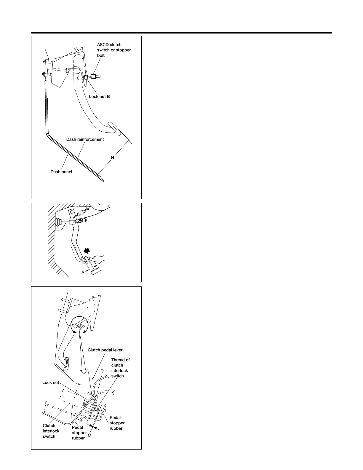
ADJUSTING CLUTCH PEDAL
Pedal Height
NICL0006
NICL0006S01
NICL0006S0101
1. Verify that clutch pedal height “H” is within specification.
쐌 Measure distance between the upper surface of dash rein-
forcement and pedal.
Pedal height “H”:
156.1 - 166.1 mm (6.146 - 6.539 in)
2. Adjust pedal free play with master cylinder push rod. Then
tighten lock nut.
Pedal free play “A”:
9 - 16 mm (0.35 - 0.63 in)
쐌 Push or step on clutch pedal until resistance is felt, and check
the distance the pedal moves.
SCL702
WCL011
3. Adjust clearance “C” shown in the figure while fully depressing
clutch pedal.
Clearance C:
0.1 - 1.0 mm (0.004 - 0.039 in)
CL-6
 Loading...