

Page 1
Edition: August 2002
Revision: November 2002
Publication No. SM2E-1B15U2
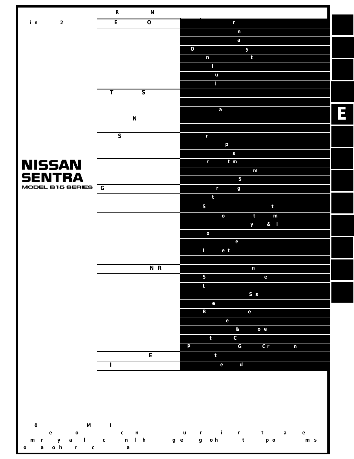
QUICK REFERENCE INDEX
A
GENERAL INFORMATION
B ENGINE
C
TRANSMISSION/
TRANSAXLE
D DRIVELINE/AXLE
E SUSPENSION
F BRAKES
G STEERING
H RESTRAINTS
I BODY
J AIR CONDITIONER
K ELECTRICAL
L MAINTENANCE
M INDEX
GI
General Information
EM
Engine Mechanical
LU
Engine Lubrication System
CO
Engine Cooling System
EC
Engine Control System
FL
Fuel System
EX
Exhaust System
ACC
Accelerator Control System
CL
Clutch
MT
Manual Transaxle
AT
Automatic Transaxle
FAX
Front Axle
RAX
Rear Axle
FSU
Front Suspension
RSU
Rear Suspension
WT
Road Wheels & Tires
BR
Brake System
PB
Parking Brake System
BRC
Brake Control System
PS
Power Steering System
SB
Seat Belts
SRS
Supplemental Restraint System (SRS)
BL
Body, Lock & Security System
GW
Glasses, Window System & Mirrors
RF
Roof
EI
Exterior & Interior
IP
Instrument Panel
SE
Seat
MTC
Manual Air Conditioner
SC
Starting & Charging System
LT
Lighting System
DI
Driver Information System
WW
Wiper, Washer & Horn
BCS
Body Control System
LAN
LAN System
AV
Audio Visual & Telephone System
ACS
Auto Cruise Control System
PG
Power Supply, Ground & Circuit Elements
MA
Maintenance
IDX
Alphabetical Index
A
B
C
D
E
F
G
H
I
J
K
L
M
© 2002 NISSAN NORTH AMERICA, INC.
All rights reserved. No part of this Service Manual may be reproduced or stored in a retrieval system, or transmitted in any
form, or by any means, electronic, mechanical, photo-copying, recording or otherwise, without the prior written permission
of Nissan North America, Inc., Gardena, California.
-1
Page 2
FOREWORD
This manual contains maintenance and repair procedures for the
2002 NISSAN SENTRA.
In order to assure your safety and the efficient functioning of the vehicle,
this manual should be read thoroughly. It is especially important that the
PRECAUTIONS in the GI section be completely understood before starting
any repair task.
All information in this manual is based on the latest product information
at the time of publication. The right is reserved to make changes in specifications and methods at any time without notice.
IMPORTANT SAFETY NOTICE
The proper performance of service is essential for both the safety of
the technician and the efficient functioning of the vehicle.
The service methods in this Service Manual are described in such a
manner that the service may be performed safely and accurately.
Service varies with the procedures used, the skills of the technician
and the tools and parts available. Accordingly, anyone using service
procedures, tools or parts which are not specifically recommended
by NISSAN must first be completely satisfied that neither personal
safety nor the vehicle’s safety will be jeopardized by the service
method selected.
-2
Page 3
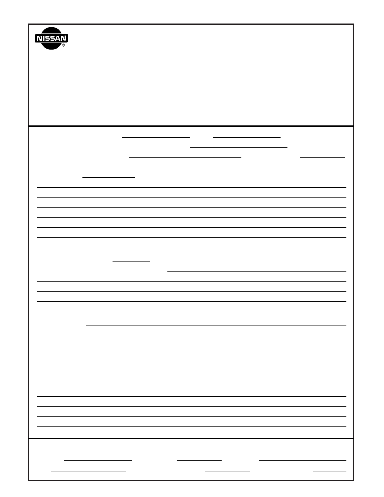
PLEASE HELP MAKE THIS SERVICE MANUAL BETTER!
Your comments are important to NISSAN and will help us to improve our Service Manuals.
Use this form to report any issues or comments you may have regarding our Service Manuals.
Please print this form and type or write your comments below. Mail or fax to:
Nissan North America, Inc.
Technical Service Information
39001 Sunrise Drive, P.O. Box 9200
Farmington Hills, MI USA 48331
FAX: (248) 488-3910
SERVICE MANUAL: Model: Year:
PUBLICATION NO. (Please photocopy back cover):
VEHICLE INFORMATION VIN: Production Date:
Please describe any issues or problems in detail:
Page number(s)
Note: Please include a copy of each page, marked with your comments.
Are the trouble diagnosis procedures logical and easy to use? (circle your answer) YES NO
If no, what pagenumber(s)?
Please describe the issue or problem in detail:
Is the organization of the manual clear and easy to follow? (circle your answer) YES NO
Please comment:
What information should be included in NISSAN Service Manuals to better support you in servicing or
repairing customer vehicles?
Note: Please include a copy of each page,markedwithyourcomments.
DATE: YOUR NAME: POSITION:
DEALER: DEALER NO.: ADDRESS:
CITY: STATE/PROV./COUNTRY: ZIP/POSTAL CODE:
Page 4
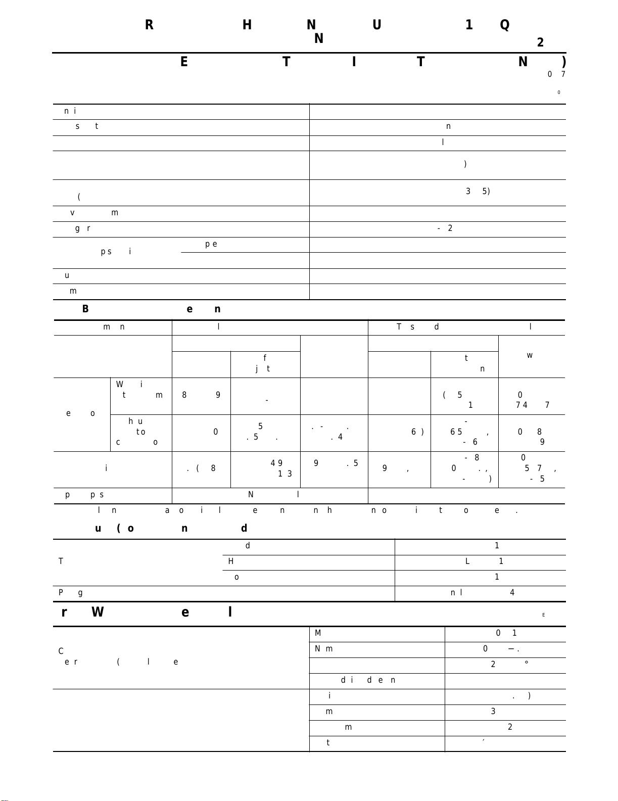
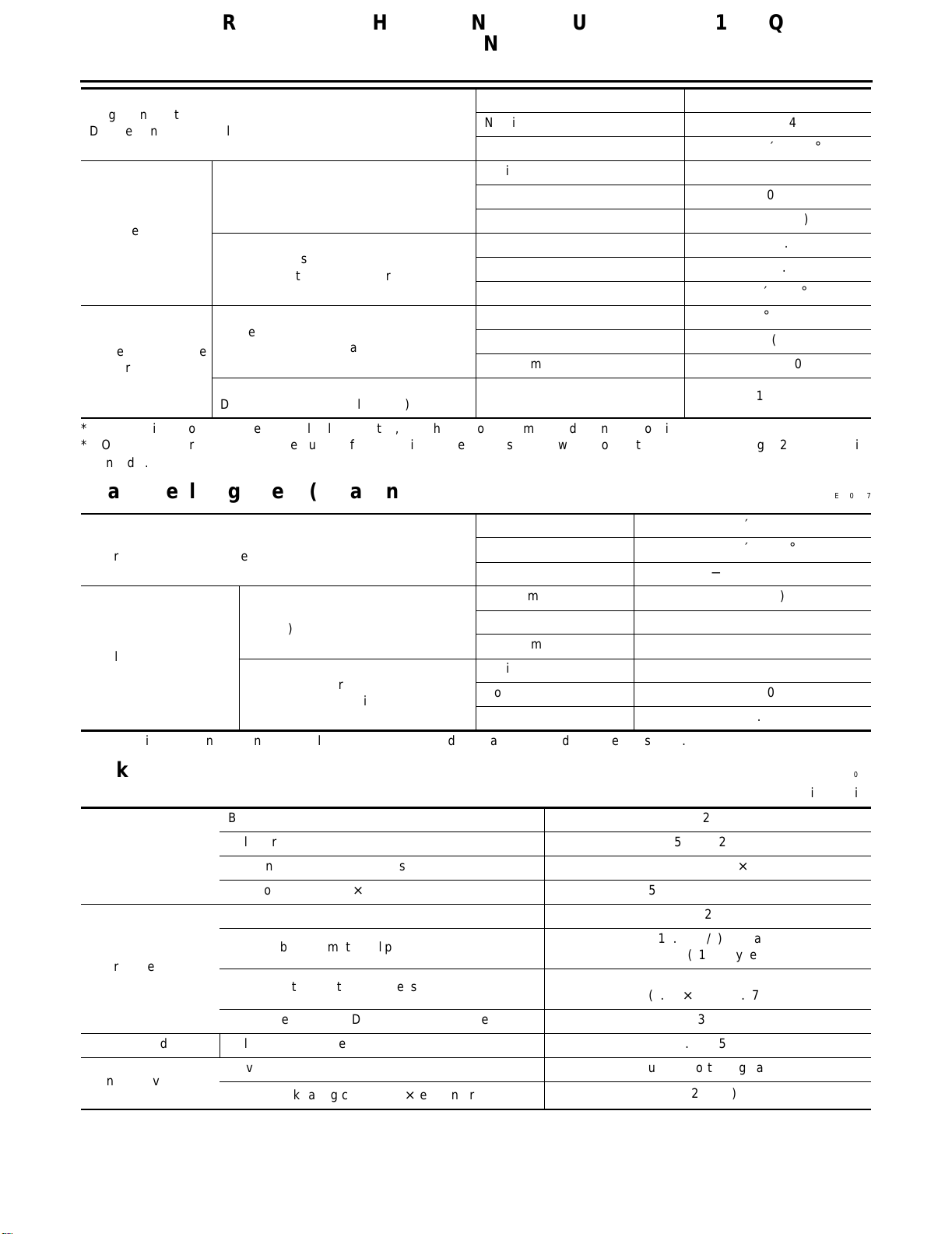
QUICK REFERENCE CHART: SENTRA (EQUIPPED WITH 1.8L, QG
ENGINE)
2002
QUICK REFERENCE CHART: SENTRA (EQUIPPED WITH 1.8L, QG ENGINE)
PFP:00027
Engine Tune-Up Data ELS000L4
Engine
Classification Gasoline
Cylinder arrangement 4, in-line
Displacement
3
(cu in)
cm
Bore × stroke
mm
(in)
Valve arrangement DOHC
Firing order 1-3-4-2
Number of piston rings
Number of main bearings 5
Compression ratio 9.5
Compression 2
Oil 1
80.0 x 88.0 (3.150 x 3.465)
Drive Belt Deflection and Tension
Component Deflection Adjustment Unit: mm (in) Tension Adjustment *1 Unit: N (kg, lb)
Used Belt
After
Limit
With air conditioner com-
Generator
Power steering oil pump 7.1 (0.280)
Applied pushing force 98 N (10 kg, 22 lb) —
*1: If the belt tension gauge cannot be installed at check points shown, check belt tension at a different location on the belt.
pressor
Without air
conditioner
compressor
8.1 (0.319)
10.2 (0.402)
(0.209 - 0.244)
(0.256 - 0.276)
(0.173 - 0.193)
Adjustment
5.3 - 5.7
6.5 - 7.0
4.4 - 4.9
New Belt
4.5 - 5.0
(0.177- 0.197)
5.5 - 6.1 (0.217
3.9 - 4.4 (0.154
- 0.240)
- 0.173)
292 (30, 66)
292 (30, 60)
196 (20, 44)
1,769 (107.94)
Used Belt
Limit
QG18DE
Adjustment
652 - 740
(66.5 - 75.5,
146.6 - 166.4)
652 - 740
(66.5 - 75.5,
146.6 - 166.4)
495 - 583
(50.5 -59.5,
111.4 - 131.2)
After
177.4 - 197.1)
177.4 - 197.1)
135.6 - 155.5)
New Belt
789 - 877
(80.5 - 89.5,
789 - 877
(80.5 - 89.5,
603- 691
(61.5 - 70.5,
Spark Plugs (Double Platinum - Tipped)
Standard PLFR5A-11
Type
Plug gap nominal 1.1 mm (0.043 in)
Hot PLFR4A-11
Cold PLFR6A-11
Front Wheel Alignment (Unladen*1) ELS000L6
Minimum −1°10' (−1.17°)
Camber
Degree minute (decimal degree)
Caster
Degree minute (decimal degree)
Nominal −0°25' (−0.42°)
Maximum 0°20′ (0.33°)
Left and right difference 45′ (0.75°) or less
Minimum 0°51′ (0.85°)
Nominal 1°36′ (1.60°)
Maximum 2°21′ (2.35°)
Left and right difference 45′ (0.75°) or less
Page 5
QUICK REFERENCE CHART: SENTRA (EQUIPPED WITH 1.8L, QG
ENGINE)
2002
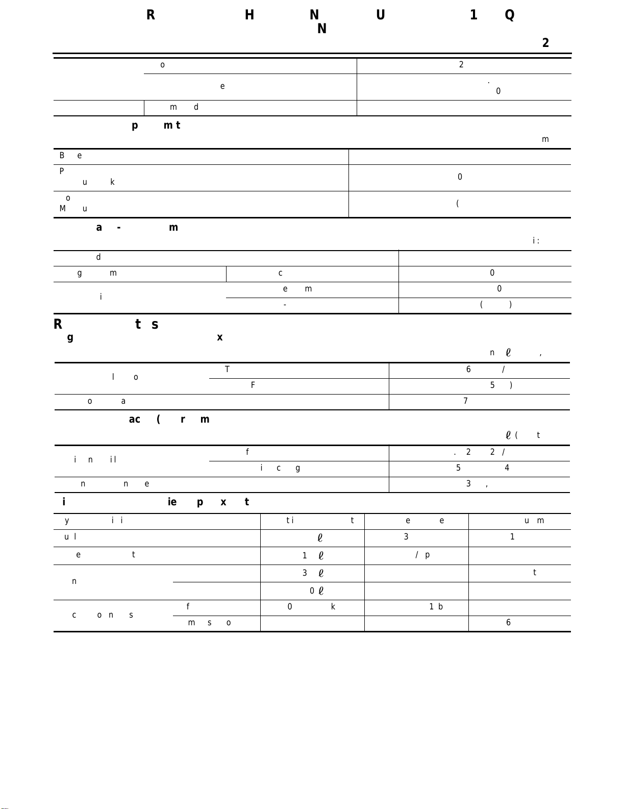
Minimum 13°58′ (13.97°)
Kingpin inclination
Degree minute (decimal degree)
Distance
mm (in)
Total toe-in
Angle (left plus right)
Degree minute (decimal degree)
Inside
Wheel turning angle
Full turn*2
*1: Fuel, radiator coolant and engine oil full. Spare tire, jack, hand tools and mats in designated positions.
*2: On power steering models, wheel turning force (at circumference of steering wheel) of 98 to 147 N (10 to 15 kg, 22 to 33 lb) with
engine idle.
Degree minute (decimal degree)
Outside
Degree minute (decimal degree)
Nominal 14°43′ (14.72°)
Maximum 15°28′ (15.47°)
Minimum 1 (0.039”)
Nominal 2 (0.079”)
Maximum 3 (0.118”)
Minimum 5.5′ (0.08°)
Nominal 11′ (0.18°)
Maximum 16′ (0.27°)
Minimum 34° (34.0°)
Nominal 37° (37.0°)
Maximum 38° (38.0°)
Nominal 31° (31.0°)
Rear Wheel Alignment (Unladen*) ELS000L7
Minimum −1°45′ (−1.75°)
Camber
Degree minute (decimal degree)
Distance
mm (in)
Tota l toe-in
Angle (left plus right)
Degree minute (decimal degree)
*: Fuel, radiator coolant and engine oil full. Spare tire, jack, hand tools and mats in designated positions.
Nominal −1°00′ (−1.00°)
Maximum −0°15′ (−0.25°)
Minimum −3 (−0.12)
Nominal 1 (0.04)
Maximum 5 (0.20)
Minimum −16′ (−0.27°)
Nominal 5′30″ (0.09°)
Maximum 26′ (0.43°)
Brake ELS000L8
Unit: mm (in)
Brake model CL25VA
Front brake
Rear brake
Master cylinder Cylinder bore diameter 23.81 (15/16)
Control valve
Cylinder bore diameter 57.2 (2.252)
Pad length × width × thickness 125.6 × 46.0 × 11.0 (4.94 × 1.811 × 0.433)
Rotor outer diameter × thickness 257 × 22 (10.12 × 0.87)
Brake model LT20G
Cylinder bore diameter/caliper bore diameter
Lining length × width × thickness
Drum inner diameter/Disc diameter × thickness 203.2 (8)
Valve model Dual proportioning valve
Split point [kPa (kg/cm
2
,
psi)] × reducing ratio
15.87 (5/8) type a
17.45 (11/16) type b
219.4 × 35 × 4.5
(8.64 × 1.38 × 0.177)
1,961 (20,284) × 0.2
Page 6
QUICK REFERENCE CHART: SENTRA (EQUIPPED WITH 1.8L, QG
ENGINE)
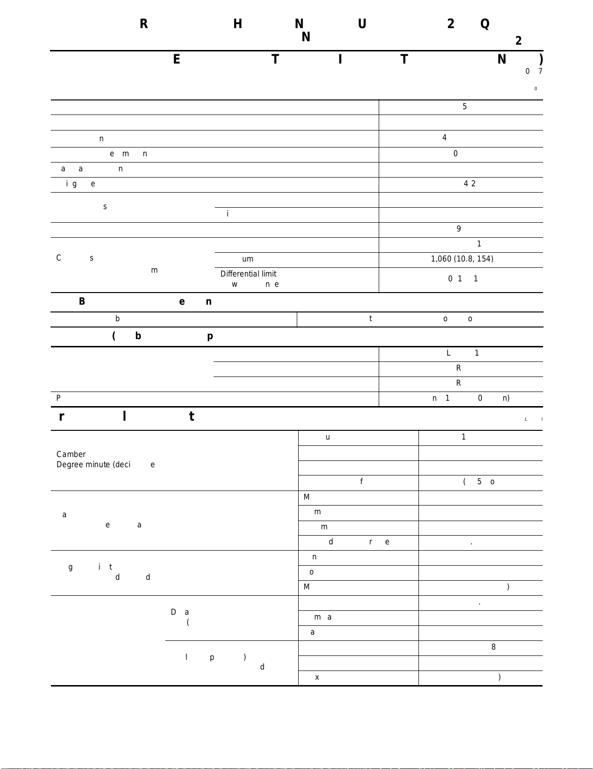
Booster model M215T
Brake booster
Brake fluid Recommended brake fluid DOT 3
Diaphragm diameter
Disc Brake - Repair Limits
Brake model CL25VA
Pad wear limit
Minimum thickness
Rotor repair limit
Minimum thickness
Drum Brake - Repair Limits
Brake model LT20G
Lining wear limit Minimum thickness 1.5 (0.059)
Drum repair limit
Maximum inner diameter 204.5 (8.05)
Maximum out-of round 0.03 (0.0012)
Primary: 230 (9.06)
Secondary: 205 (8.07)
2.0 (0.079)
20 (0.79)
2002
Unit: mm (in)
Unit: mm (in)
Refill Capacities ELS000LC
Engine Coolant Capacity (Approximate)
Unit:
(US qt, Imp qt)
Drain and refill without reservoir
Reservoir tank (at MAX level) 0.7 (3/4, 5/8)
Engine Oil Capacity (Approximate)
Drain and refill
Dry engine (engine overhaul) 3.1 (3 1/4, 2 3/4)
Miscellaneous Capacities (Approximate)
System description Metric measurement US measurement Imp measurement
Fuel tank
Power steering system
Transaxle
Air conditioning system
M/T (RS5F70A)
A/T (RE4F03B)
refrigerant 0.45 - 0.55 kg 0.99 - 1.21 lb —
compressor oil 180 ml 6.1 fl oz 6.3 fl oz
M/T (RS5F70A) 6.0 (6 3/8, 5 1/4)
A/T (RE4F03B) 5.9 (6 1/4, 5 1/4)
Unit:
With oil filter change 2.7 (2 7/8, 2 3/8)
Without oil filter change 2.5 (2 5/8, 2 1/4)
50
1.0
3.0
7.0
13 1/4 gal 11 gal
2 1/8 pt 1 3/4 pt
3 1/8 qt 2 5/8 qt
7 3/8 qt 6 1/8 qt
(US qt, Imp qt)
Page 7
QUICK REFERENCE CHART: SENTRA (EQUIPPED WITH 2.5L, QR
ENGINE)
2002
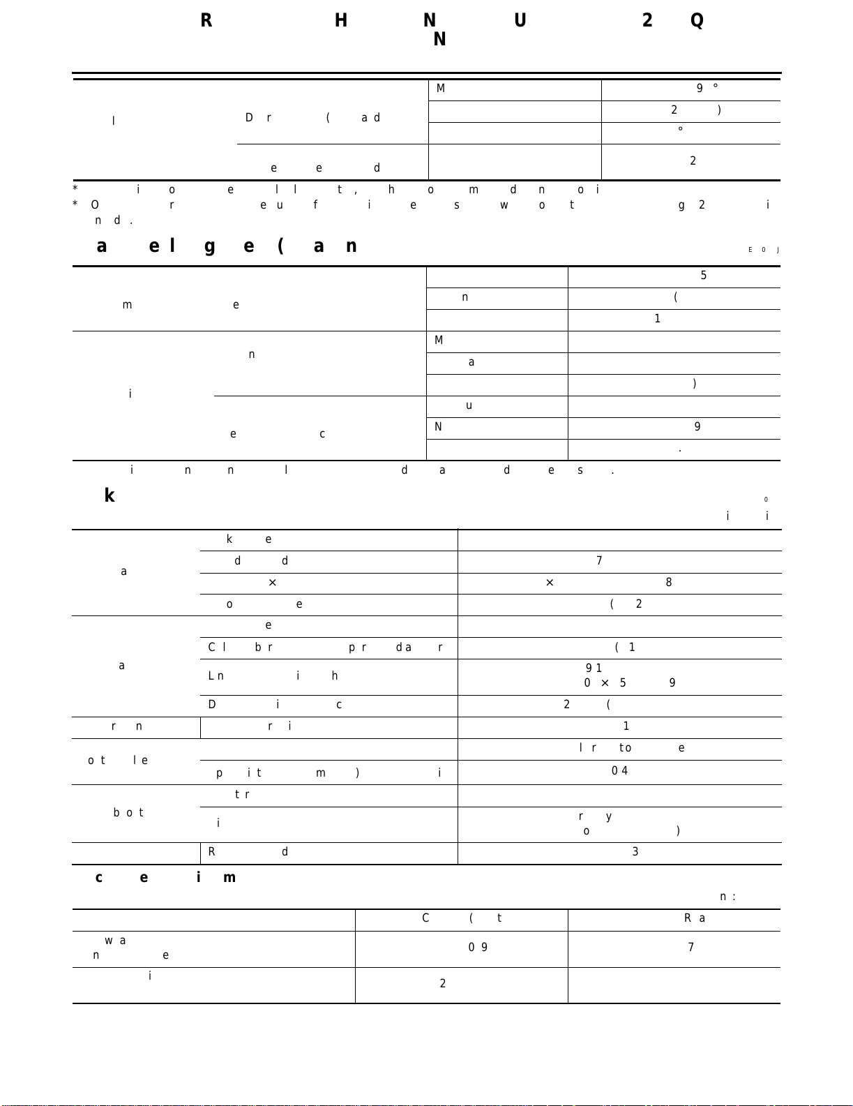
QUICK REFERENCE CHART: SENTRA (EQUIPPED WITH 2.5L, QR ENGINE)
PFP:00027
Engine Tune-Up Data ELS000LF
Engine QR25DE
Cylinder arrangement 4 in-line
3
Displacement cm
Bore and stroke mm (in) 89.0 x 100 (3.50 - 3.94)
Valve arrangement DOHC
Firing order 1-3-4-2
Number of piston rings
Compression ratio 9.5
Compression pressure
kPa (kg/cm
2
,
(cu in)
psi) / 250 rpm
Compression 2
Oil 1
Standard 1,250 (12.8, 182)
Minimum 1,060 (10.8, 154)
Differential limit
between cylinders
Drive Belt Deflection and Tension
Tension of drive belts
Auto adjustment by auto-tensioner
2,488 (151.82)
100 (1.0, 14)
Spark Plugs (Double Platinum Tipped)
Standard PLFR5A-11
Type
Plug gap nominal 1.1 mm (0.043 in)
Hot PLFR4A-11
Cold PLFR6A-11
Front Wheel Alignment (Unladen*1) ELS000LI
Minimum −1°12' (−1.2°)
Camber
Degree minute (decimal degree)
Caster
Degree minute (decimal degree)
Kingpin inclination
Degree minute (decimal degree)
Distance
mm (in)
Tota l toe-in
Angle (left plus right)
Degree minute (decimal degree)
Nominal −0°27' (−0.45°)
Maximum 0°18′ (0.3°)
Left and right difference 45′ (0.75°) or less
Minimum 0°58′ (0.97°)
Nominal 1°43′ (1.72°)
Maximum 2°28′ (2.47°)
Left and right difference 45′ (0.75°) or less
Minimum 14°03′ (14.05°)
Nominal 14°46′ (14.77°)
Maximum 15°31′ (15.52°)
Minimum 1 (0.039”)
Nominal 2 (0.079”)
Maximum 3 (0.118”)
Minimum 5.5′ (0.08°)
Nominal 11′ (0.18°)
Maximum 16′ (0.27°)
Page 8
QUICK REFERENCE CHART: SENTRA (EQUIPPED WITH 2.5L, QR
ENGINE)
2002
Minimum 29° (29.0°)
Inside
Wheel turning angle
Full turn*2
*1: Fuel, radiator coolant and engine oil full. Spare tire, jack, hand tools and mats in designated positions.
*2: On power steering models, wheel turning force (at circumference of steering wheel) of 98 to 147 N (10 to 15 kg, 22 to 33 lb) with
engine idle.
Degree minute (decimal degree)
Outside
Degree minute (decimal degree)
Nominal 32° (32.0°)
Maximum 33° (33.0°)
Nominal 27° (27.0°)
Rear Wheel Alignment (Unladen*) ELS000LJ
Minimum −1°45′ (−1.75°)
Camber
Degree minute (decimal degree)
Distance
mm (in)
Tota l toe-in
Angle (left plus right)
Degree minute (decimal degree)
*: Fuel, radiator coolant and engine oil full. Spare tire, jack, hand tools and mats in designated positions.
Nominal −1°00′ (−1.00°)
Maximum −0°15′ (−0.25°)
Minimum −3 (−0.12)
Nominal 1 (0.04)
Maximum 5 (0.20)
Minimum −16′ (−0.27°)
Nominal 5′30″ (0.09°)
Maximum 26′ (0.43°)
Brake ELS000LK
Unit: mm (in)
Brake model CL25VB
Front brake
Rear brake
Master cylinder Cylinder bore diameter 23.81 (15/16)
Control valve
Brake booster
Brake fluid Recommended brake fluid DOT 3
Disc Brake - Repair Limits
Brake model CL25VB (Front) CL9HC (Rear)
Pad wear limit
Minimum thickness
Rotor repair limit
Minimum thickness
Cylinder bore diameter 57.2 (2.252)
Pad length × width × thickness 125.6 × 46.0 × 11.0 (4.94 × 1.811 × 0.433)
Rotor outer diameter × thickness 280 × 22 (11.02 × 0.87)
Brake model CL9HC
Cylinder bore diameter/caliper bore diameter 33.96 (1 11/32)
Lining length × width × thickness
Drum inner diameter/Disc diameter × thickness 258 × 9 (10.16 × 0.35)
Valve model Dual proportioning valve
Split point [kPa (kg/cm
Booster model M215T
Diaphragm diameter
2
,
psi)] × reducing ratio
2.0 (0.079) 2.0 (0.079)
20 (0.79) 8 (0.31)
89.1 × 39.5 × 10
(3.508 × 1.555 × 0.39)
2,942 (30,427) × 0.2
Primary: 230 (9.06)
Secondary: 205 (8.07)
Unit: mm (in)
MA-2
Page 9
QUICK REFERENCE CHART: SENTRA (EQUIPPED WITH 2.5L, QR
ENGINE)
2002
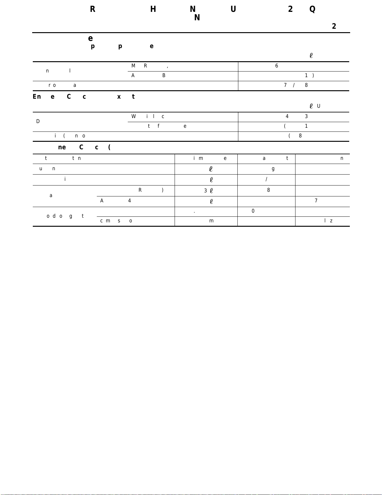
Refill Capacities ELS000LN
Engine Coolant Capacity (Approximate)
Unit:
(US qt, Imp qt)
Drain and refill (without reservoir)
Reservoir tank (at MAX level) 0.7 (3/4, 5/8)
Engine Oil Capacity (Approximate)
Drain and refill
Dry engine (engine overhaul) 4.6 (4 7/8, 4)
Miscellaneous Capacity (Approximate)
System description Metric measurement US measurement Imp measurement
Fuel tank
Power steering system
Transaxle
Air conditioning system
M/T (RS5F51A, RS6F51H)
A/T (RE4F04B)
refrigerant 0.45 - 0.55 kg 0.99 - 1.21 lb —
compressor oil 180 ml 6.1 fl oz 6.3 fl oz
M/T (RS5F51A, RS6F51H) 6.0 (6 3/8, 5 1/4)
A/T (RE4F04B) 5.9 (6 1/4, 5 1/4)
Unit:
With oil filter change 4.2 (4 1/2, 3 3/4)
Without oil filter change 4.0 (4 1/4, 3 1/2)
50
1.0
2.3
8.5
13 1/4 gal 11 gal
2 1/8 pt 1 3/4 pt
2 3/8 qt 2 qt
9 qt 7 1/2 qt
(US qt, Imp qt)
Page 10
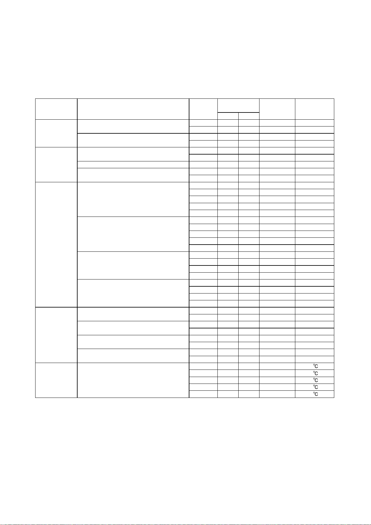
TEST VALUE AND TEST LIMIT (GST ONLY — NOT APPLICABLE TO CONSULT-II)
The following is the information specified in Mode 6 of SAE J1979.
The test value is a parameter used to determine whether a system/circuit diagnostic test is “OK” or “NG” while
being monitored by the ECM during self-diagnosis. The test limit is a reference value which is specified as the
maximum or minimum value and is compared with the test value being monitored.
Items for which these data (test value and test limit) are displayed are the same as SRT code items.
These data (test value and test limit) are specified by Test ID (TID) and Component ID (CID) and can be dis-
played on the GST screen.
SRT item Self-diagnostic test item DTC
QG18DE (Except CALIF. CA)
Three way catalyst function (Bank 1)
CATALYST
Three way catalyst function (Bank 2)
EVAP control system (Small leak)
EVAP SYSTEM
HO2S
HO2S HTR
EGR SYSTEM EGR function
EVAP control system purge flow monitoring P0441 06H 83H Min. 20mV
EVAP control system (Very small leak)
Heated oxygen sensor 1 (Bank 1)
Heated oxygen sensor 1 (Bank 2)
Heated oxygen sensor 2 (Bank 1)
Heated oxygen sensor 2 (Bank 2)
Heated oxygen sensor 1 heater (Bank 1)
Heated oxygen sensor 1 heater (Bank 2)
Heated oxygen sensor 2 heater (Bank 1)
Heated oxygen sensor 2 heater (Bank 2)
Attachment No.24
Test value
(GST display)
TID CID
P0420 01H 01H Max. 1/128
P0420 02H 81H Min. 1
P0430 03H 02H Max. 1/128
P0430 04H 82H Min. 1
P0442 05H 03H Max.
P1442 05H 03H Max.
P0456 07H 03H Max.
P1456 07H 03H Max.
P0133 09H 04H Max. 16ms
P1143 0AH 84H Min. 10mV
P1144 0BH 04H Max. 10mV
P0132 0CH 04H Max. 10mV
P0134 0DH 04H Max. 1s
P0153 11H 05H Max. 16ms
P1163 12H 85H Min. 10mV
P1164 13H 05H Max. 10mV
P0152 14H 05H Max. 10mV
P0154 15H 05H Max. 1s
P0139 19H 86H Min. 10mV/500ms
P1147 1AH 86H Min. 10mV
P1146 1BH 06H Max. 10mV
P0138 1CH 06H Max. 10mV
P0159 21H 87H Min. 10mV/500ms
P1167 22H 87H Min. 10mV
P1166 23H 07H Max. 10mV
P0158 24H 07H Max. 10mV
P0032 29H 08H Max. 20mV
P0031 2AH 88H Min. 20mV
P0052 2BH 09H Max. 20mV
P0051 2CH 89H Min. 20mV
P0038 2DH 0AH Max. 20mV
P0037 2EH 8AH Min. 20mV
P0058 2FH 0BH Max. 20mV
P0057 30H 8BH Min. 20mV
P0400 31H 8CH Min. 1
P0400 32H 8CH Min. 1
P0400 33H 8CH Min. 1
P0400 34H 8CH Min. 1
P1402 35H 0CH Max. 1
Test limit
Conversion
1/128mm
1/128mm
1/128mm
1/128mm
2
2
2
2
Page 11
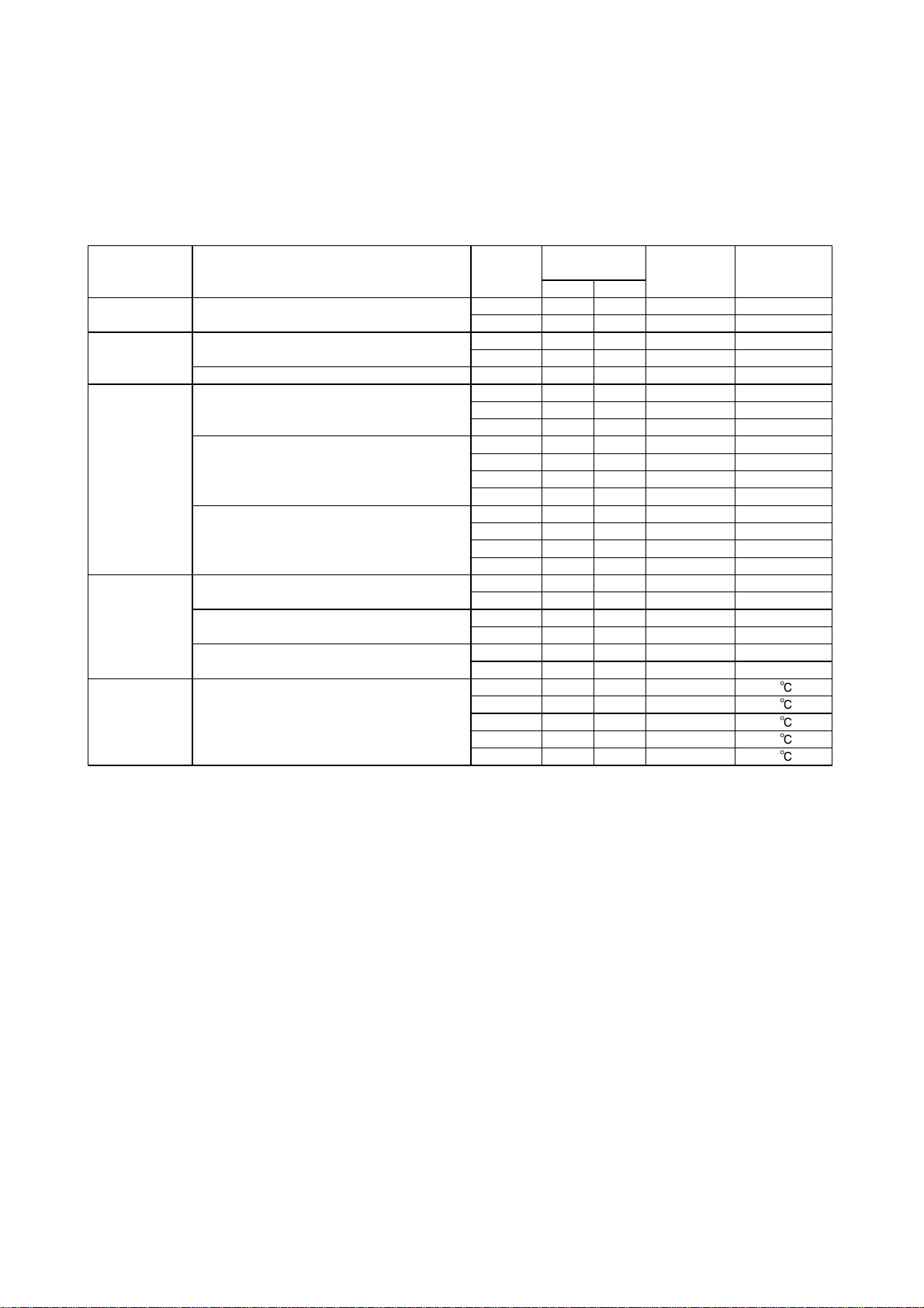
TEST VALUE AND TEST LIMIT (GST ONLY — NOT APPLICABLE TO CONSULT-II)
The following is the information specified in Mode 6 of SAE J1979.
The test value is a parameter used to determine whether a system/circuit diagnostic test is “OK” or “NG” while
being monitored by the ECM during self-diagnosis. The test limit is a reference value which is specified as the
maximum or minimum value and is compared with the test value being monitored.
Items for which these data (test value and test limit) are displayed are the same as SRT code items.
These data (test value and test limit) are specified by Test ID (TID) and Component ID (CID) and can be dis-
played on the GST screen.
SRT item Self-diagnostic test item DTC
QG18DE (CALIF. CA)
CATALYST Three way catalyst function
EVAP SYSTEM
HO2S
HO2S HTR
EGR SYSTEM EGR function
EVAP control system (Small leak)
EVAP control system purge flow monitoring P0441 06H 83H Min. 20mV
A/F sensor 1
Heated oxygen sensor 2
Heated oxygen sensor 3
A/F sensor 1 heater
Heated oxygen sensor 2 heater
Heated oxygen sensor 3 heater
Attachment No.25
Test value
(GST display)
TID CID
P0420 01H 01H Max. 1/128
P0420 02H 81H Max. 1
P0442 05H 03H Max.
P1442 05H 03H Max.
P1273 43H 0EH Max. 0.002
P1274 44H 8EH Min. 0.002
P1275 45H 8EH Min. 0.004
P0139 19H 86H Min. 10mV/500ms
P1147 1AH 86H Min. 10mV
P1146 1BH 06H Max. 10mV
P0138 1CH 06H Max. 10mV
P0145 61H 92H Min. 10mV/500ms
P0144 62H 92H Min. 10mV
P0143 63H 12H Max. 10mV
P0146 64H 12H Max. 10mV
P1277 57H 04H Max. 5mV
P1277 58H 04H Min. 5mV
P0141 2DH 0AH Max. 20mV
P0141 2EH 8AH Min. 20mV
P0147 71H 14H Max. 20mV
P0147 72H 94H Min. 20mV
P0400 31H 8CH Min. 1
P0400 32H 8CH Min. 1
P0400 33H 8CH Min. 1
P0400 34H 8CH Min. 1
P1402 35H 0CH Max. 1
Test limit
Conversion
1/128mm
1/128mm
2
2
Page 12
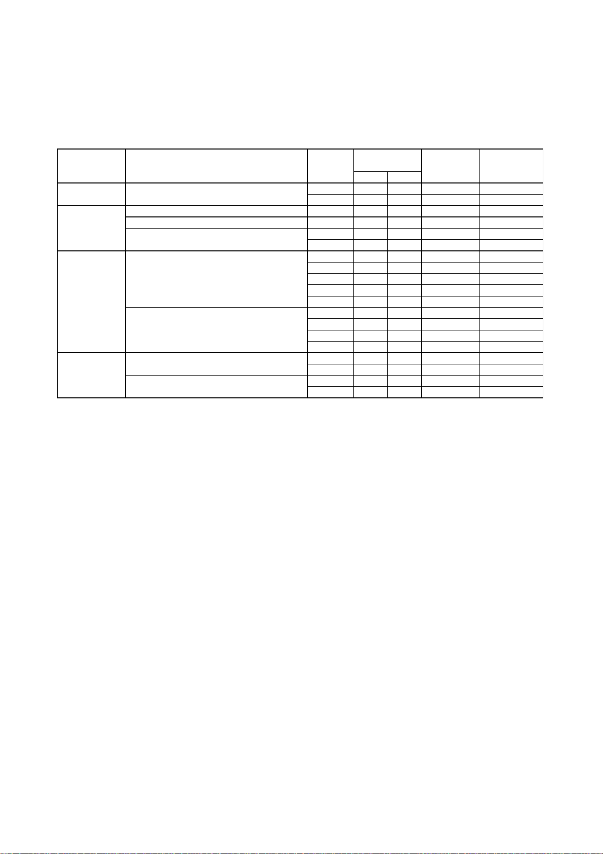
SRT item Self-diagnostic test item DTC
TEST VALUE AND TEST LIMIT (GST ONLY — NOT APPLICABLE TO CONSULT-II)
The following is the information specified in Mode 6 of SAE J1979.
These data (test value and test limit) are specified by Test ID (TID) and Component ID (CID) and can be dis-
played on the GST screen.
The test value is a parameter used to determine whether a system/circuit diagnostic test is “OK” or “NG” while
being monitored by the ECM during self-diagnosis. The test limit is a reference value which is specified as the
maximum or minimum value and is compared with the test value being monitored.
QR25DE
CATALYST Three way catalyst function
EVAP control system (Small leak) P0442 05H 03H Max.
EVAP SYSTEM
HO2S
HO2S HTR
EVAP control system purge flow monitoring P0441 06H 83H Min. 20mV
EVAP control system (Very small leak)
Heated oxygen sensor 1
Heated oxygen sensor 2
Heated oxygen sensor 1 heater
Heated oxygen sensor 2 heater
Attachment No.26
Test value
(GST display)
TID CID
P0420 01H 01H Max. 1/128
P0420 02H 81H Min. 1
P0456 07H 03H Max.
P1456 07H 03H Max.
P0133 09H 04H Max. 16ms
P1143 0AH 84H Min. 10mV
P1144 0BH 04H Max. 10mV
P0132 0CH 04H Max. 10mV
P0134 0DH 04H Max. 1s
P0139 19H 86H Min. 10mV/500ms
P1147 1AH 86H Min. 10mV
P1146 1BH 06H Max. 10mV
P0138 1CH 06H Max. 10mV
P0032 29H 08H Max. 20mV
P0031 2AH 88H Min. 20mV
P0038 2DH 0AH Max. 20mV
P0037 2EH 8AH Min. 20mV
Test limit
Conversion
1/128mm
1/128mm
1/128mm
2
2
2
Page 13
B ENGINE
SECTION
A
ACC
ACCELERA T OR CONTROL SYSTEM
CONTENTS
QG18DE
ACCELERATOR CONTROL SYSTEM ...................... 2
Removal and Installation .......................................... 2
Adjusting Accelerator Wire ....................................... 2
QR25DE
ACCELERATOR CONTROL SYSTEM .......................4
Removal and Installation ..........................................4
C
D
E
F
G
H
I
J
M
K
L
ACC-1
Page 14
ACCELERATOR CONTROL SYSTEM
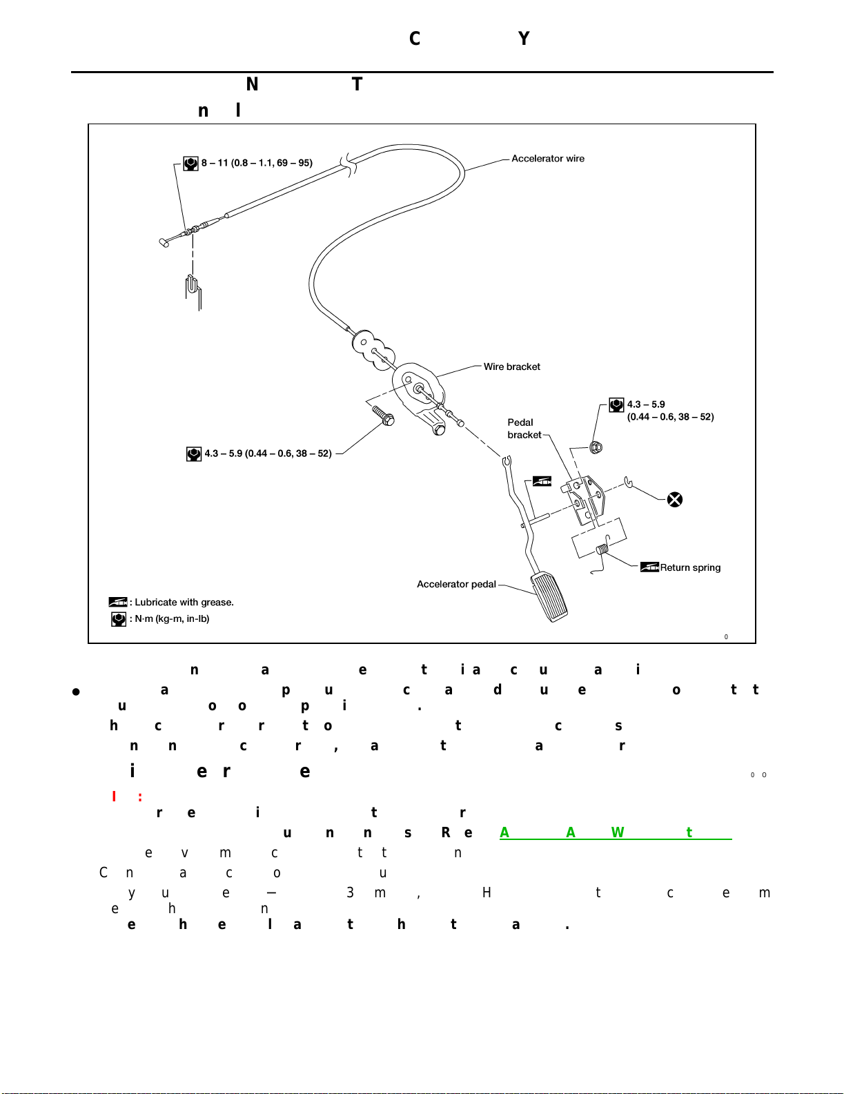
[QG18DE]
ACCELERATOR CONTROL SYSTEM
PFP:18005
Removal and Installation EBS007OJ
WFE005
CAUTION:
● When
● Check
removing accelerator wire, make a mark to indicate lock nut's initial position.
that throttle valve opens fully when accelerator pedal is fully depressed. Also check that it
returns to idle position when pedal is released.
● Check
● When
accelerator control parts for improper contact with any adjacent parts.
connecting accelerator wire, be careful not to twist or scratch its inner wire.
Adjusting Accelerator Wire EBS007OK
CAUTION:
● Make
● Perform
1. Remove the vacuum hose connected to the throttle opener.
2. Connect suitable vacuum hose to vacuum pump.
3. Apply vacuum [more than −40.0 kPa (−300 mmHg, −11.81 inHg)] until the throttle drum becomes free from
sure the ASCD wire is not pulling the throttle drum.
the ASCD wire adjustment as necessary. Refer to ACS-23, "ASCD Wire Adjustment" .
the rod of the throttle opener.
Make sure that there is clearance between the throttle drum and rod.
ACC-2
Page 15
ACCELERATOR CONTROL SYSTEM
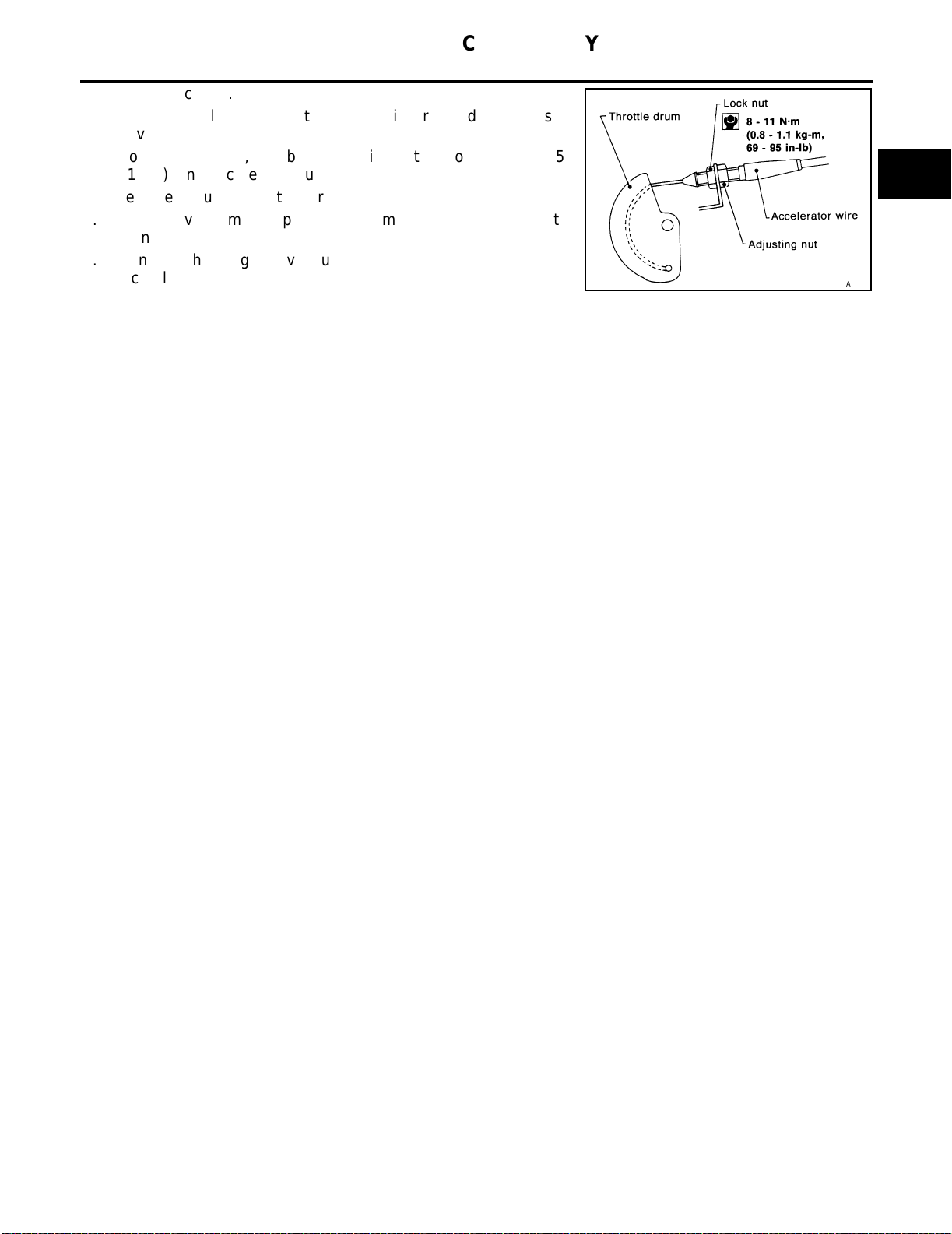
4. Loosen lock nut.
5. Tighten accelerator adjusting nut until throttle drum starts to
move.
6. From that position, turn back adjusting nut 3.9 to 4.5 mm (0.15 -
0.18 in), and secure lock nut.
7. Release vacuum from the throttle opener.
8. Remove vacuum pump and vacuum hose from the throttle
opener.
9. Reinstall the original vacuum hose to the throttle opener
securely.
[QG18DE]
A
ACC
C
SFE249AE
D
E
F
G
M
H
I
J
K
L
ACC-3
Page 16
ACCELERATOR CONTROL SYSTEM
[QR25DE]
ACCELERATOR CONTROL SYSTEM
PFP:18005
Removal and Installation EBS007OL
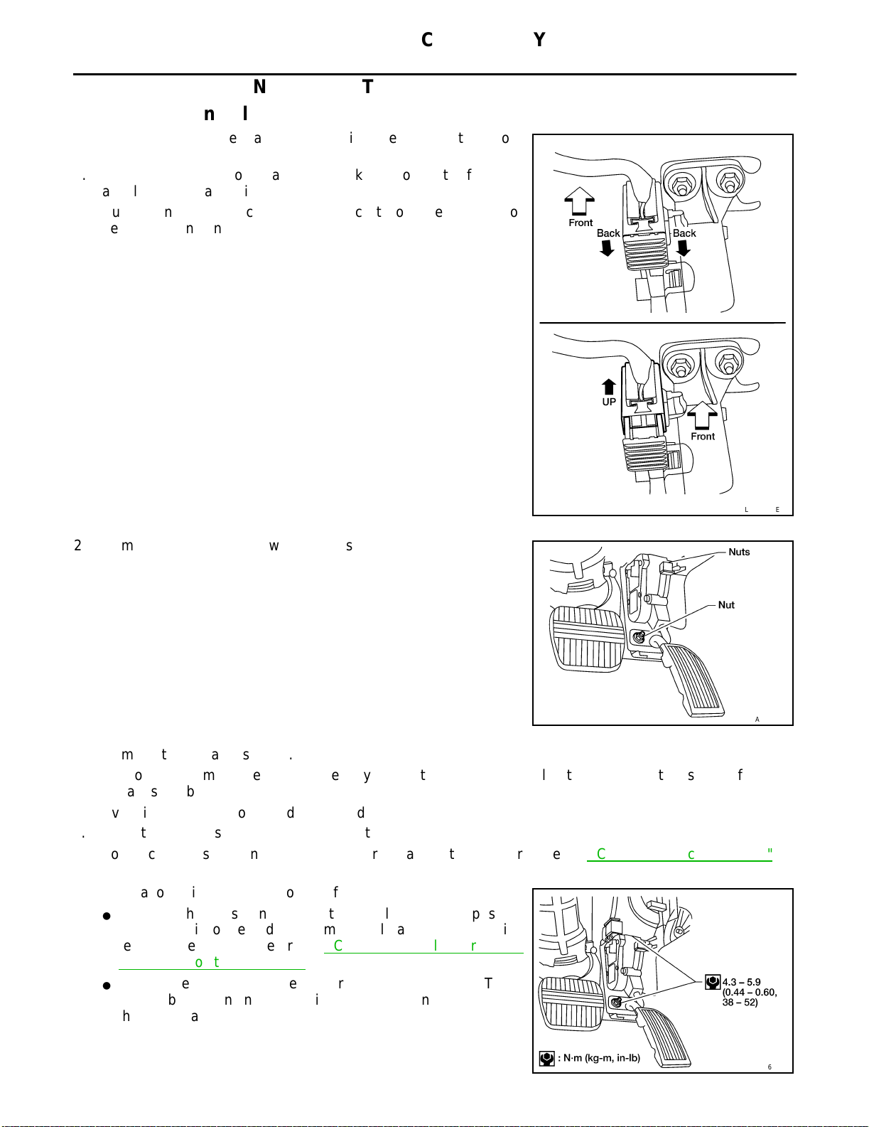
1. Disconnect the accelerator pedal position sensor electrical connector.
a. Pull the connector lock back to unlock the connector from the
accelerator pedal position sensor.
b. Pull up on the connector to disconnect it from the accelerator
pedal position sensor.
LBIA0075E
2. Remove the upper and lower pedal assembly nuts.
LBIA0060E
3. Remove the pedal assembly.
a. Do not disassemble the pedal assembly. Do not remove the accelerator pedal position sensor from the
pedal assembly.
b. Avoid impact from dropping during handling.
c. Keep the pedal assembly away from water.
d. For electrical inspection of the accelerator pedal position sensor. Refer to EC-1289, "
Basic Inspection" .
4. Installation is in the reverse order of removal.
● When
the harness connector of the accelerator pedal position
sensor is disconnected, perform "Accelerator pedal position
released learning". Refer to EC-1253, "
Accelerator Pedal
Released Position Learning" .
● Check
the accelerator pedal for smooth operation. There
should be no binding or sticking when applying or releasing
the accelerator pedal.
ACC-4
LBIA0061E
Page 17
ACCELERATOR CONTROL SYSTEM
[QR25DE]
● Check
that the accelerator pedal moves through the full spec-
ified distance of pedal travel.
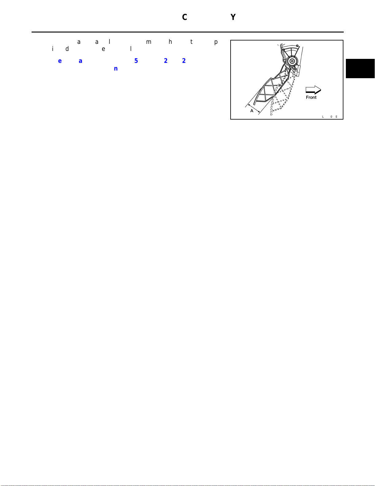
Pedal Travel "A" : 52.6 - 58.2 mm (2.07 - 2.29
in)
A
ACC
C
LBIA0062E
D
E
F
G
H
M
I
J
K
L
ACC-5
Page 18

ACCELERATOR CONTROL SYSTEM
[QR25DE]
ACC-6
Page 19

K ELECTRICAL
SECTION
A
B
AUTO CRUISE CONTROL SYSTEM
CONTENTS
QG18DE
PRECAUTIONS .......................................................... 2
Precautions for Supplemental Restraint System
(SRS) “AIR BAG” and “SEAT BELT PRE-TEN-
SIONER” ..................................................................2
Wiring Diagrams and Trouble Diagnosis .................. 2
AUTOMATIC SPEED CONTROL DEVICE (ASCD) ..... 3
Component Parts and Harness Connector Location ..... 3
System Description .................................................. 5
POWER SUPPLY AND GROUND ........................ 5
OPERATION ......................................................... 5
ASCD MOTOR ACTUATOR OPERATION ........... 6
Schematic ................................................................ 7
Wiring Diagram — ASCD — .................................... 8
FIG. 1 ..................................................................... 8
FIG. 2 ..................................................................... 9
FIG. 3 ................................................................... 10
FIG. 4 ....................................................................11
Fail-safe System .................................................... 12
DESCRIPTION .................................................... 12
MALFUNCTION DETECTION CONDITIONS ..... 12
Trouble Diagnoses ................................................. 13
SYMPTOM CHART ............................................. 13
FAIL-SAFE SYSTEM CHECK ............................. 14
POWER SUPPLY AND GROUND CIRCUIT
CHECK ................................................................15
ASCD BRAKE/STOP LAMP SWITCH CHECK ...16
ASCD STEERING SWITCH CHECK ..................18
VEHICLE SPEED SENSOR CHECK ..................19
ASCD MOTOR ACTUATOR CIRCUIT CHECK ...19
ASCD MOTOR ACTUATOR CHECK ..................21
Electrical Component Inspection ............................22
ASCD STEERING SWITCH ................................22
ASCD BRAKE SWITCH AND STOP LAMP
SWITCH ..............................................................22
ASCD CLUTCH SWITCH (M/T) ..........................22
PARK/NEUTRAL POSITION SWITCH (A/T) .......22
PARK/NEUTRAL POSITON (PNP) RELAY .........23
ASCD Wire Adjustment ..........................................23
QR25DE
PRECAUTIONS ........................................................24
Precautions for Supplemental Restraint System
(SRS) “AIR BAG” and “SEAT BELT PRE-TEN-
SIONER” .................................................................24
Wiring Diagrams and Trouble Diagnosis ................24
AUTOMATIC SPEED CONTROL DEVICE (ASCD) ...25
Description ..............................................................25
C
D
E
F
G
H
I
J
ACS
L
M
ACS-1
Page 20
PRECAUTIONS
[QG18DE]
PRECAUTIONS
Precautions for Supplemental Restraint System (SRS) “AIR BAG” and “SEAT
BELT PRE-TENSIONER”
PFP:00001
EKS0043V
The Supplemental Restraint System such as “AIR BAG” and “SEAT BELT PRE-TENSIONER”, used along
with a front seat belt, helps to reduce the risk or severity of injury to the driver and front passenger for certain
types of collision. Information necessary to service the system safely is included in the SRS and SB section of
this Service Manual.
WARNING:
● To
avoid rendering the SRS inoperative, which could increase the risk of personal injury or death
in the event of a collision which would result in air bag inflation, all maintena nce must be performed by an authorized NISSAN/INFINITI dealer.
● Improper
maintenance, including incorrect removal and installation of the SRS, can lead to personal injury caused by unintentional activation of the system. For removal of Spiral Cable and Air
Bag Module, see the SRS section.
● Do
not use electrical test equipment on any circuit related to the SRS unless instructed to in this
Service Manual. SRS wiring harnesses can be identified by yellow and/or orange harness connectors.
Wiring Diagrams and T rouble Diagnosis EKS0043R
When you read wiring diagrams, refer to the following:
● GI-13,
● PG-2,
When you perform trouble diagnosis, refer to the following:
● GI-10,
● GI-26,
Check for any Service bulletins before servicing the vehicle.
"How to Read Wiring Diagrams"
"POWER SUPPLY ROUTING "
"HOW TO FOLLOW TEST GROUPS IN TROUBLE DIAGNOSES"
"How to Perform Efficient Diagnosis for an Electrical Incident"
ACS-2
Page 21
AUTOMATIC SPEED CONTROL DEVICE (ASCD)
[QG18DE]
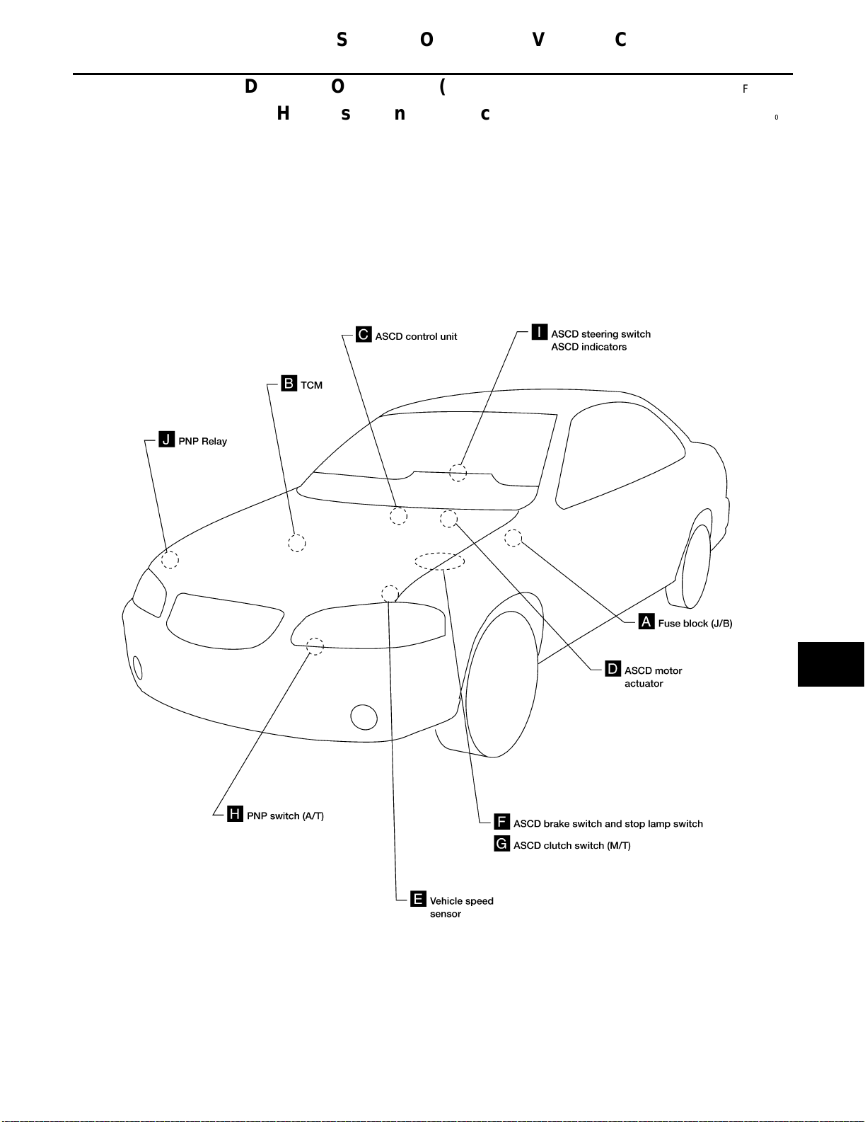
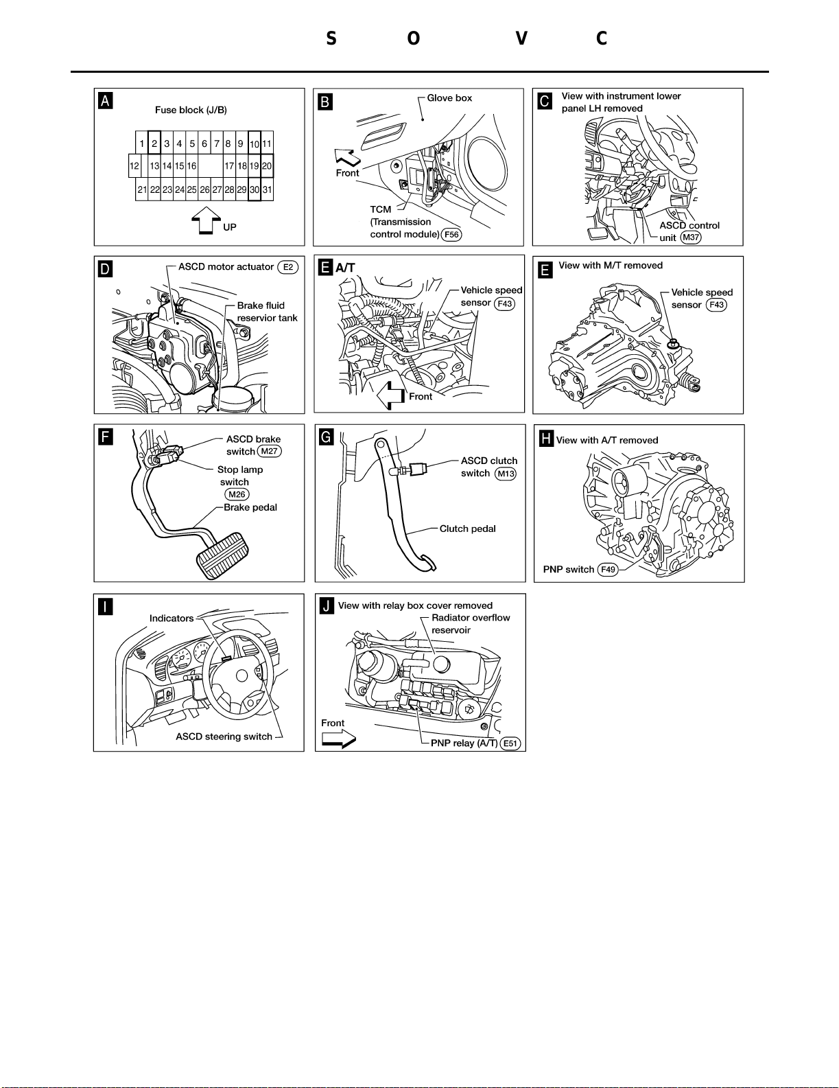
AUTOMATIC SPEED CONTROL DEVICE (ASCD) PFP:18930
Component Parts and Harness Connector Location EKS002CK
A
B
C
D
E
F
G
H
I
J
ACS
L
M
ACS-3
WKIA0002E
Page 22
AUTOMATIC SPEED CONTROL DEVICE (ASCD)
[QG18DE]
ACS-4
WKIA0003E
Page 23
AUTOMATIC SPEED CONTROL DEVICE (ASCD)
[QG18DE]
System Description EKS002CL
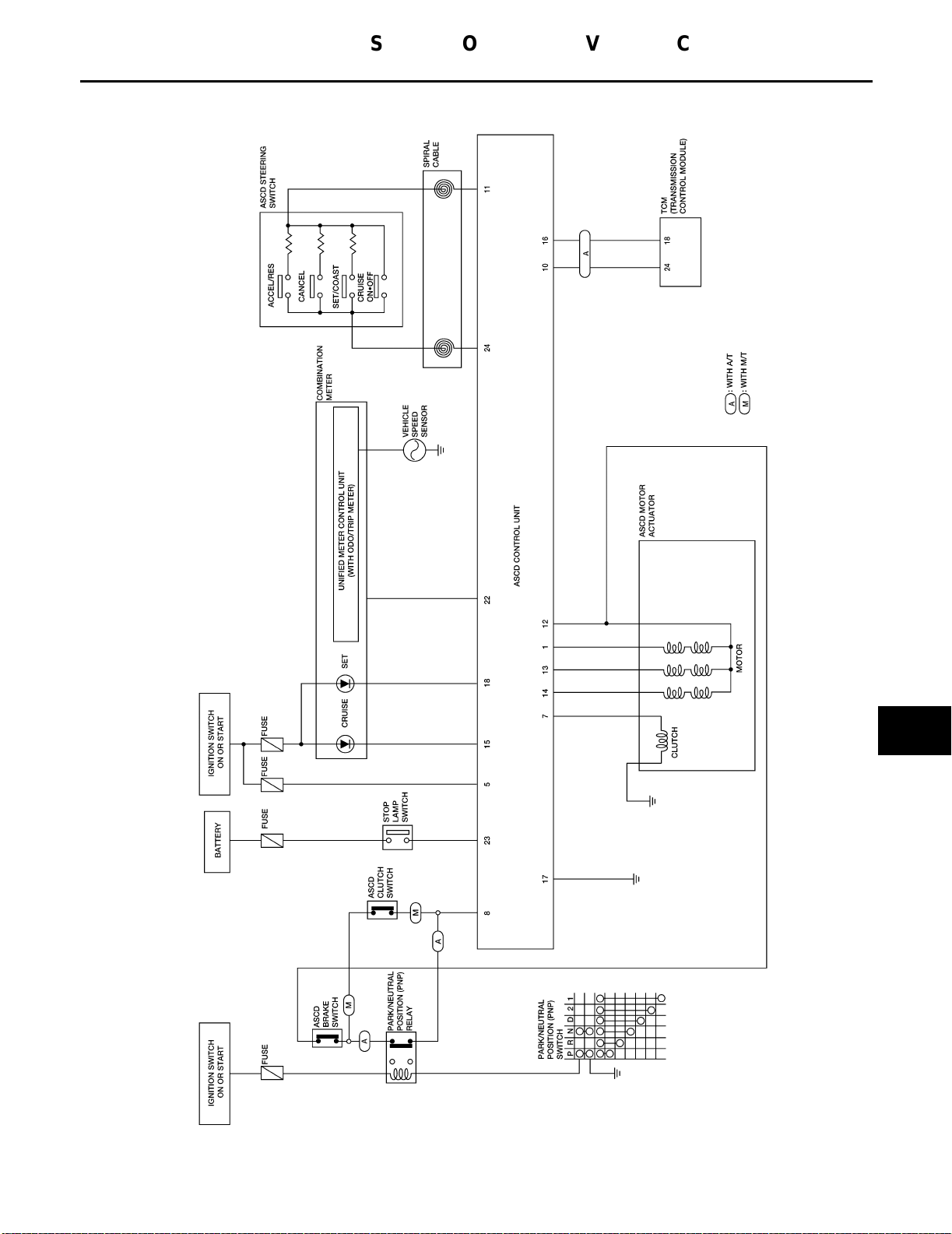
Refer to Owner's Manual for ASCD operating instructions.
POWER SUPPLY AND GROUND
Power is supplied at all times:
● through
● to
When ignition switch is in the ON or START position, power is supplied:
● through
● to
● through
● to
● through
● to
When park/neutral position switch (A/T) is in the P or N position, ground is supplied:
● to
● through
When ASCD CRUISE/ON●OFF switch is depressed (ON), ground is supplied:
● to
● from
● to
● from
Then ASCD control unit illuminates CRUISE indicator.
Ground is supplied:
● to
● from
Ground is supplied:
● to
● through
OPERATION
Set Operation
To activate the ASCD, all of following conditions must exist:
● ASCD
● Power
is released and A/T selector lever is in other than P and N position. (A/T)]
● Vehicle
When the SET/COAST switch is depressed, ground is supplied:
● to
● from
Then ASCD motor actuator is activated to control throttle wire and ASCD control unit supplies ground:
● to
10A fuse [No. 2, located in the fuse block (J/B)]
the stop lamp switch terminal +.
10A fuse [No. 10, located in the fuse block (J/B)]
ASCD control unit terminal 5.
10A fuse [No. 20, located in the fuse block (J/B)]
park/neutral position relay terminal 1
10A fuse [No. 30, located in the fuse block (J/B)]
combination meter terminals 6 and 21.
park/neutral position (PNP) relay terminal 2
body grounds F33, F35, and F37.
ASCD control unit terminal 11
ASCD steering switch terminal 4
ASCD steering switch terminal 1
ASCD control unit terminal 24.
combination meter terminal 22
ASCD control unit terminal 15.
ASCD control unit terminal 17
body grounds M28 and M54.
control unit receives ASCD CRUISE/ON●OFF switch ON signal
supply to ASCD control unit terminal 8 [Brake and clutch pedal is released (M/T), and brake pedal
speed is between 40 km/h (25 MPH) and 144 km/h (89 MPH). (Signal from combination meter)
ASCD control unit terminal 11
ASCD steering switch terminal 4.
combination meter terminal 7 to illuminate SET indicator.
A
B
C
D
E
F
G
H
I
J
ACS
L
M
A/T Overdrive Control During Cruise Control Driving (A/T)
When the vehicle speed is approximately 5 km/h (3 MPH) below set speed, a signal is sent:
● from
● to
ASCD control unit terminal 10
TCM terminal 24.
When this occurs, the TCM cancels overdrive.
When vehicle speed returns to approximately 0.6 km/h (0.4 MPH) below set speed, overdrive is reactivated.
ACS-5
Page 24
AUTOMATIC SPEED CONTROL DEVICE (ASCD)
[QG18DE]
Coast Operation
When the SET/COAST switch is depressed during cruise control driving, ASCD motor actuator returns the
throttle cable to decrease vehicle set speed until the switch is released. Then ASCD will keep the new set
speed.
If SET/COAST switch is pressed and released quickly during cruise control driving, vehicle set speed will be
reduced by 1.6 km/h (1.0 MPH).
Accel Operation
When the ACCEL/RES switch is depressed, ground is supplied:
● from
● to
If the ACCEL/RES switch is depressed during cruise control driving, ASCD motor actuator pulls the throttle
cable to increase the vehicle speed until the switch is released or vehicle speed reaches maximum controlled
speed by the system. Then ASCD will keep the new set speed.
If ACCEL/RES switch is pressed and released quickly during cruise control driving, vehicle set speed will be
increased by 1.6 km/h (1.0 MPH).
Cancel Operation
When any of following conditions exist, cruise operation will be canceled:
● CANCEL
● Brake
● Brake
If CRUISE/ON●OFF switch is turned to OFF when ASCD is activated, all of ASCD operation will be canceled
and vehicle speed memory will be erased.
ASCD steering switch terminal 4
ASCD control unit terminal 11.
switch is depressed. (Ground is supplied to ASCD control unit terminal 11)
pedal is depressed. (Power is supplied to ASCD control unit terminal 23 from stop lamp switch)
or
clutch pedal is depressed (M/T), brake pedal is depressed or A/T selector lever is shifted to P or
N position (A/T). (Power supply to ASCD control unit terminal 8 is interrupted.)
Resume Operation
When the ACCEL/RES switch is depressed, after cancel operation other than depressing CRUISE/ON●OFF
switch is performed, vehicle speed will return to last set speed. To resume vehicle set speed, vehicle condition
must meet following conditions:
● Brake
● Clutch
● A/T
● Vehicle
pedal is released.
pedal is released (M/T).
selector lever is in other than P and N position (A/T).
speed is between 40 km/h (25 MPH) and 144 km/h (89 MPH).
ASCD MOTOR ACTUATOR OPERATION
When the ASCD activates, power is supplied:
● from
● to
● from
● to
Ground is supplied:
● from
● to
Power to the actuator motor is supplied constantly from the ASCD control unit. The ASCD control unit then
switches the actuator motor ground signals ON and OFF to control actuator motor operation and vehicle
speed.
terminal 7 of ASCD control unit
ASCD motor actuator terminal 1, and
terminal 12 of ASCD control unit
ASCD motor actuator terminal 6.
ASCD control unit terminals 1, 13, and 14
terminals 3, 5, and 2 of ASCD motor actuator.
ACS-6
Page 25
AUTOMATIC SPEED CONTROL DEVICE (ASCD)
[QG18DE]
Schematic EKS002CM
A
B
C
D
E
F
G
H
I
J
ACS
L
M
ACS-7
WKWA0008E
Page 26
AUTOMATIC SPEED CONTROL DEVICE (ASCD)
[QG18DE]
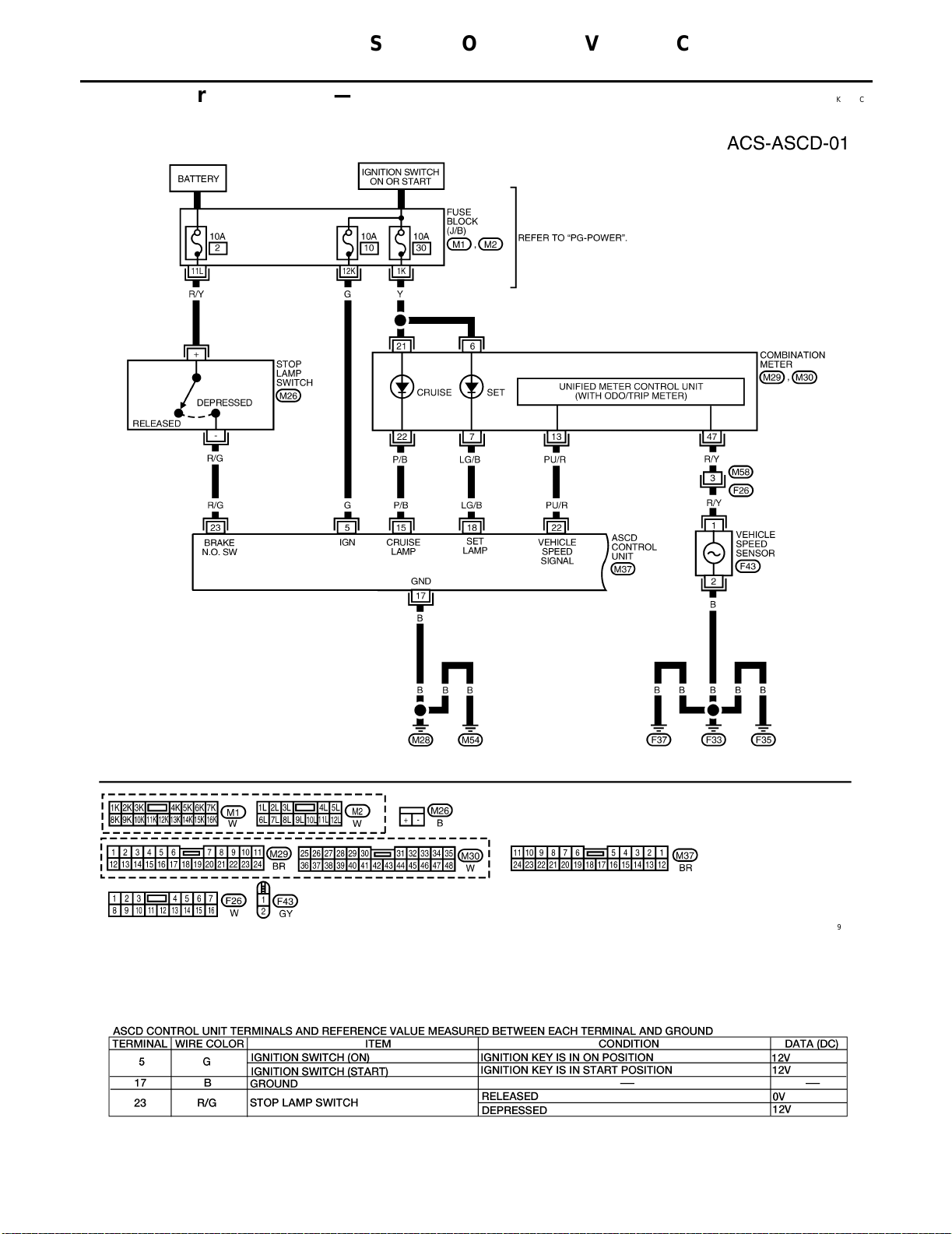
Wiring Diagram — ASCD —
FIG. 1
EKS002CN
ACS-8
WKWA0009E
LEL601
Page 27
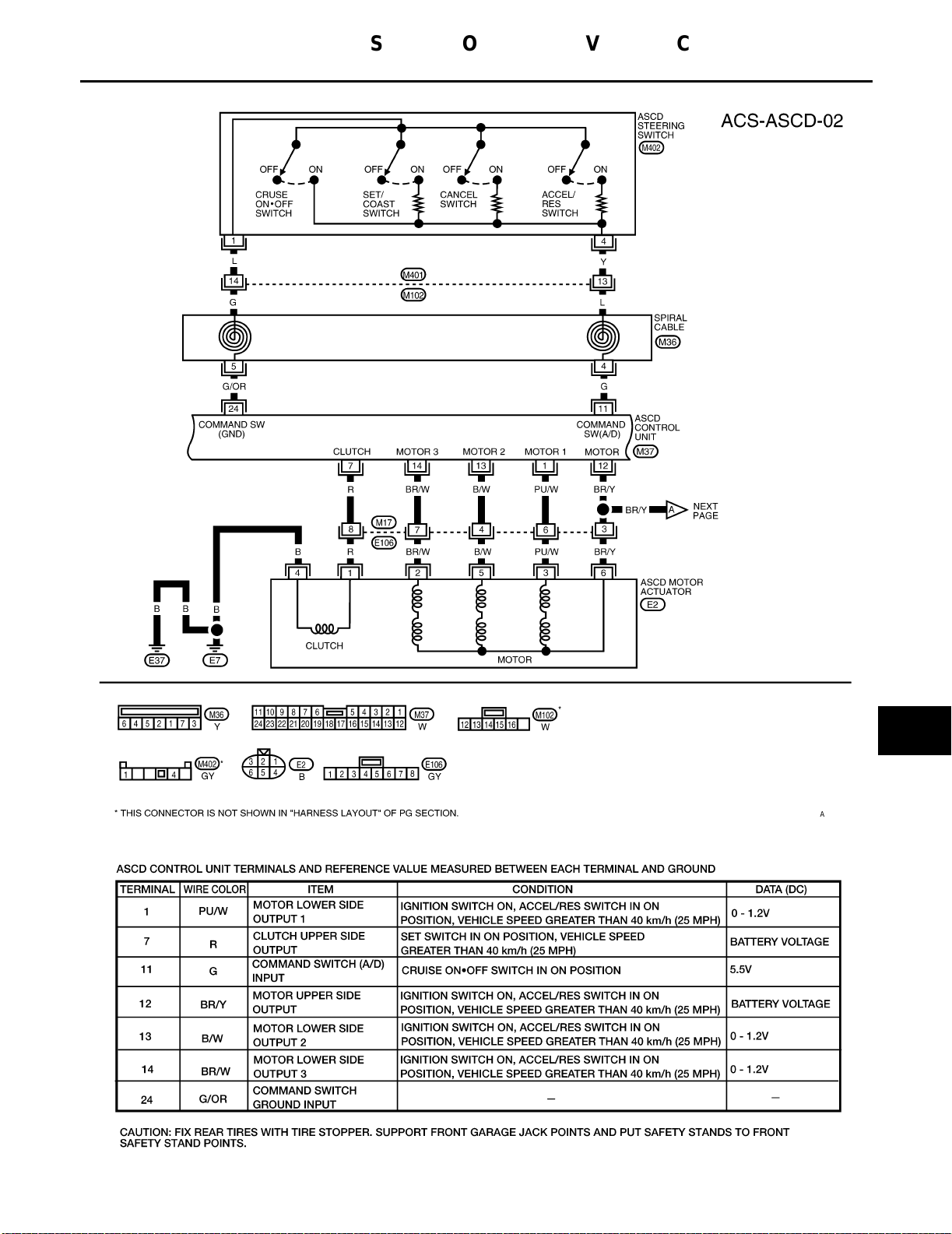
FIG. 2
AUTOMATIC SPEED CONTROL DEVICE (ASCD)
[QG18DE]
A
B
C
D
E
F
G
WKWA0010E
H
I
J
ACS
L
M
ACS-9
WEL431A
Page 28
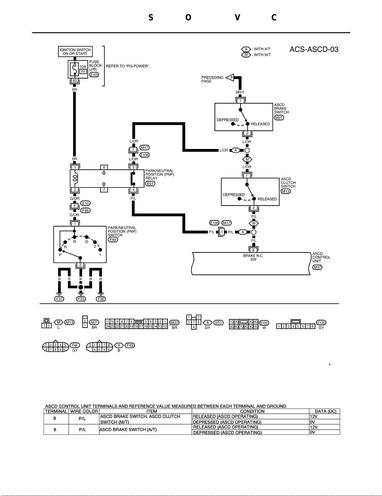
FIG. 3
AUTOMATIC SPEED CONTROL DEVICE (ASCD)
[QG18DE]
ACS-10
WKWA0011E
LEL602
Page 29
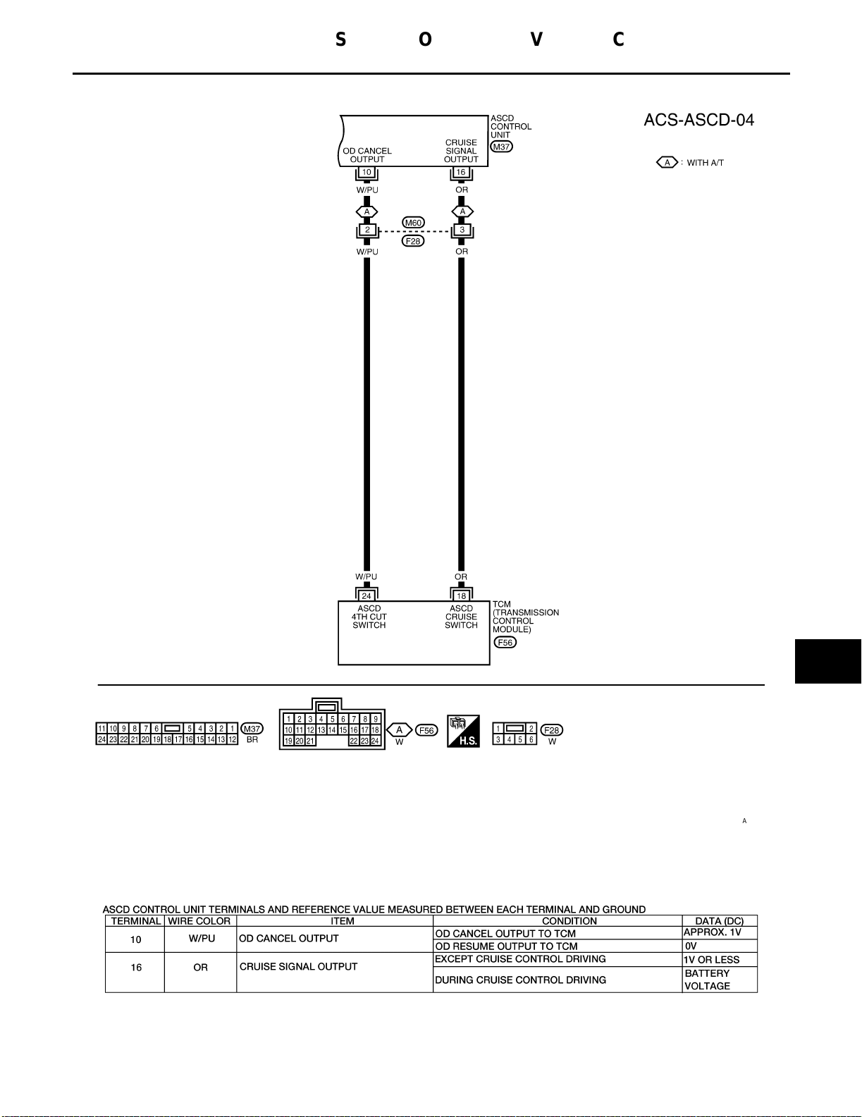
FIG. 4
AUTOMATIC SPEED CONTROL DEVICE (ASCD)
[QG18DE]
A
B
C
D
E
F
G
WKWA0012E
H
I
J
ACS
L
M
ACS-11
WEL098A
Page 30
AUTOMATIC SPEED CONTROL DEVICE (ASCD)
[QG18DE]
Fail-safe System
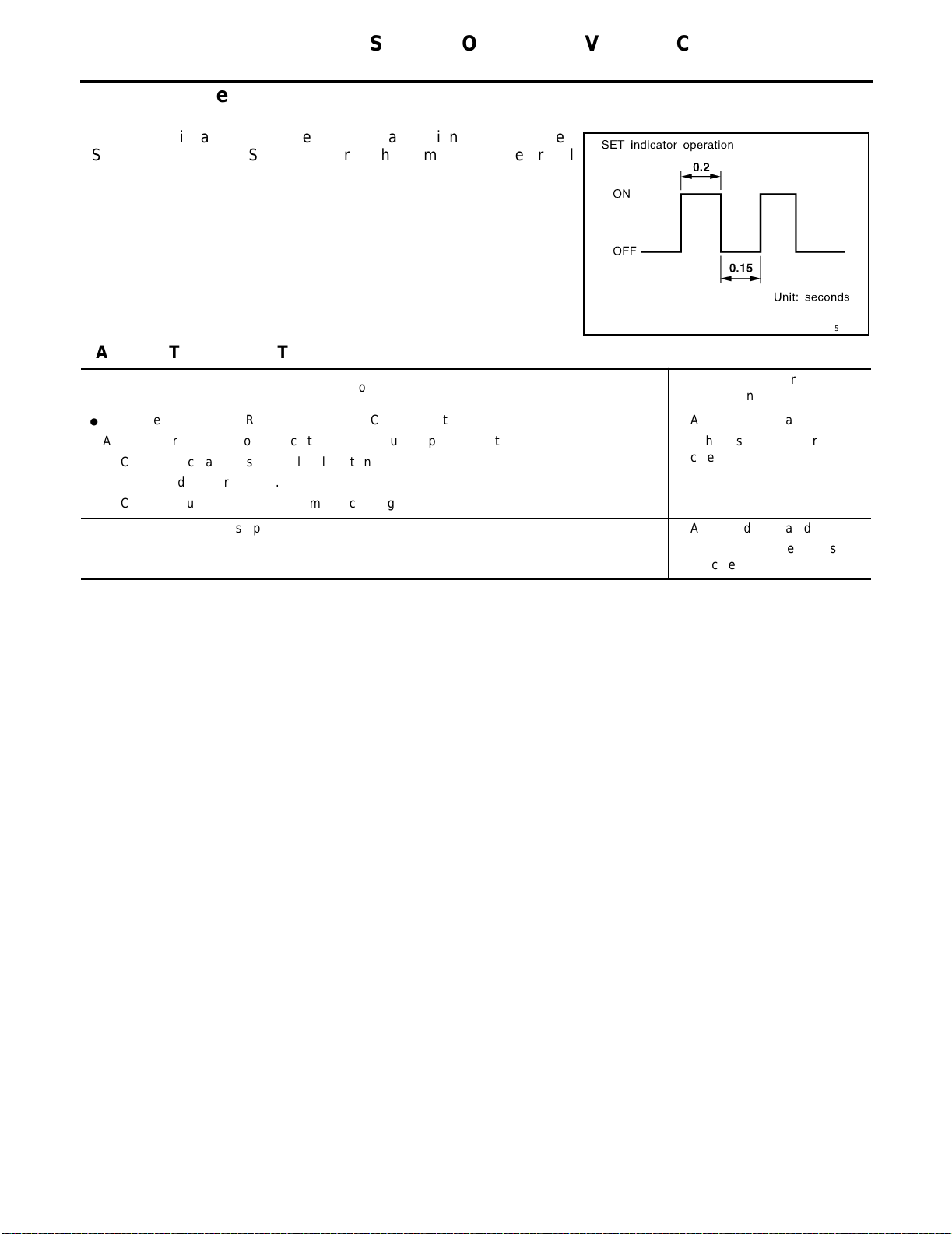
DESCRIPTION
When the fail-safe system senses a malfunction, it deactivates
ASCD operation. The SET indicator in the combination meter will
then flash.
MALFUNCTION DETECTION CONDITIONS
Detection conditions
● ASCD
● ASCD
● ASCD
● Vehicle
● ASCD
● ASCD
steering (ACCEL/RES, CANCEL, SET/COAST) switch is stuck.
motor actuator ground circuit or power circuit is open or shorted.
motor actuator has internal malfunction.
speed sensor is faulty.
control unit internal circuit is malfunctioning.
brake switch or stop lamp switch is faulty. ● ASCD is deactivated.
EKS002CO
SEL255W
ASCD operation during malfunc-
tion detection
● ASCD
● Vehicle
● Vehicle
is
celed.
canceled.
deactivated.
speed memory is can-
speed memory is not
ACS-12
Page 31
AUTOMATIC SPEED CONTROL DEVICE (ASCD)
[QG18DE]
T rouble Diagnoses EKS002CP
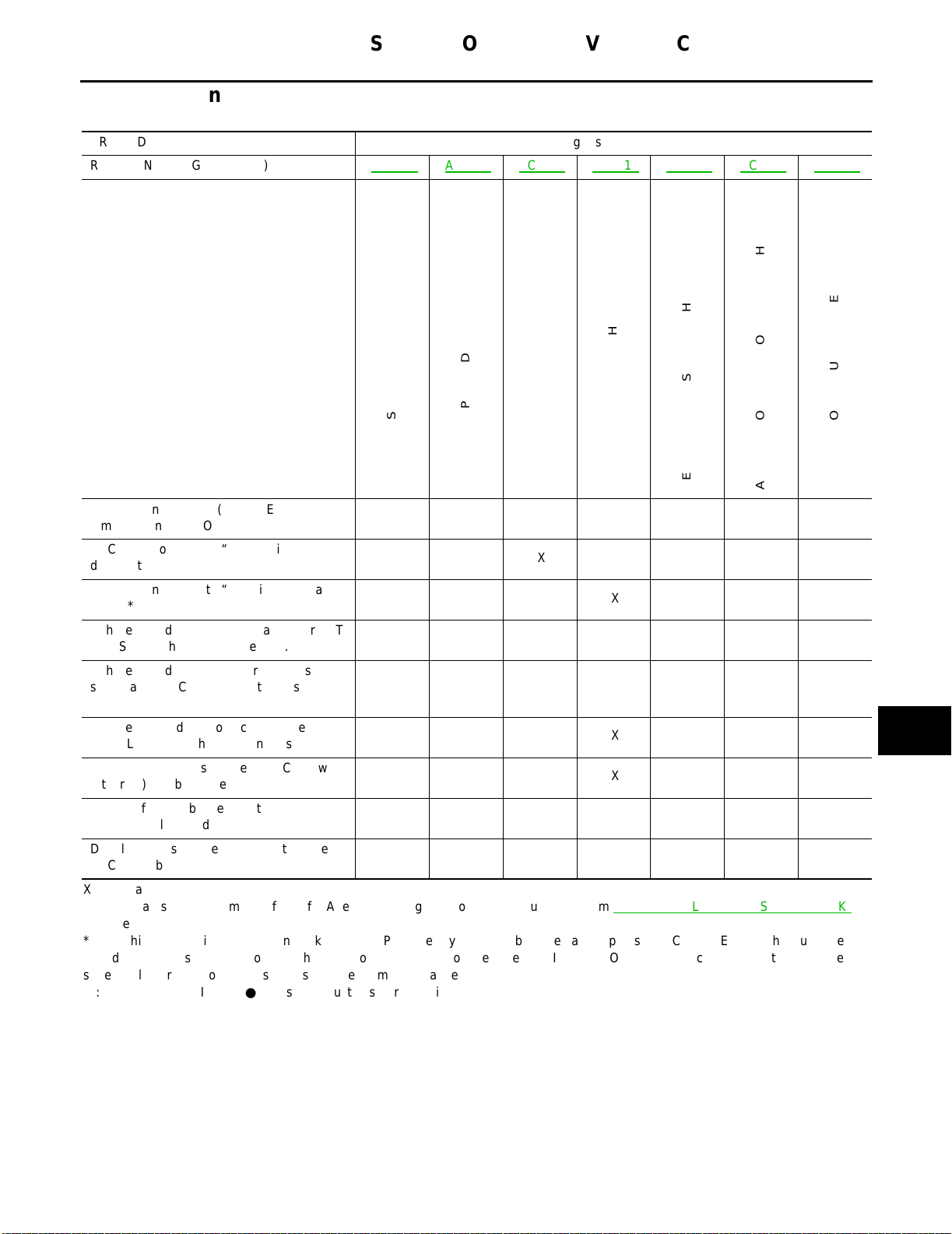
SYMPTOM CHART
PROCEDURE Diagnostic procedure
REFERENCE PAGE (ACS- ) ACS-14
SYMPTOM
CHECK
SYSTEM
ACS-15 ACS-16 ACS-18 ACS-19 ACS-19 ACS-21
CHECK
CHECK
CIRCUIT
ACTUATOR
MOTOR
CHECK
ACTUATOR
MOTOR
CIRCUIT
GROUND
AND
SUPPLY
CHECK
SWITCH
LAMP
BRAKE/STOP
CHECK
SWITCH
STEERING
CHECK
SENSOR
SPEED
A
B
C
D
E
F
FAIL-SAFE
ASCD cannot be set. (“CRUISE” indicator
lamp does not turn ON.)
ASCD cannot be set. (“SET” indicator lamp
does not turn ON.)
ASCD cannot be set. (“SET” indicator lamp
blinks.*1)
Vehicle speed does not decrease after SET/
COAST switch has been pressed.
Vehicle speed does not return to the set
speed after ACCEL/RES switch has been
pressed.*2
Vehicle speed does not increase after
ACCEL/RES switch has been pressed.
System is not released after CANCEL switch
(steering) has been pressed.
Large difference between set speed and
actual vehicle speed.
Deceleration is greatest immediately after
ASCD has been set.
X: Applicable
*1: It indicates that system is in fail-safe. After completing diagnostic procedures, perform ACS-14, "
verify repairs.
*2: If vehicle speed is greater than 40 km/h (25 MPH) after system has been released, pressing ACCEL/RES switch returns vehicle
speed to the set speed previously achieved. However, doing so when the CRUISE ON●OFF main switch is turned to “OFF”, vehicle
speed will not return to the set speed since the memory is canceled.
*3: Check only CRUISE ON●OFF switch built-in steering switch.
XXXXX
POWER
XX*3
ASCD
XXX
ASCD
XX
XX
XX
XX
VEHICLE
XXX
XXX
FAIL-SAFE SYSTEM CHECK" to
ASCD
ASCD
G
H
I
J
ACS
L
M
ACS-13
Page 32
AUTOMATIC SPEED CONTROL DEVICE (ASCD)
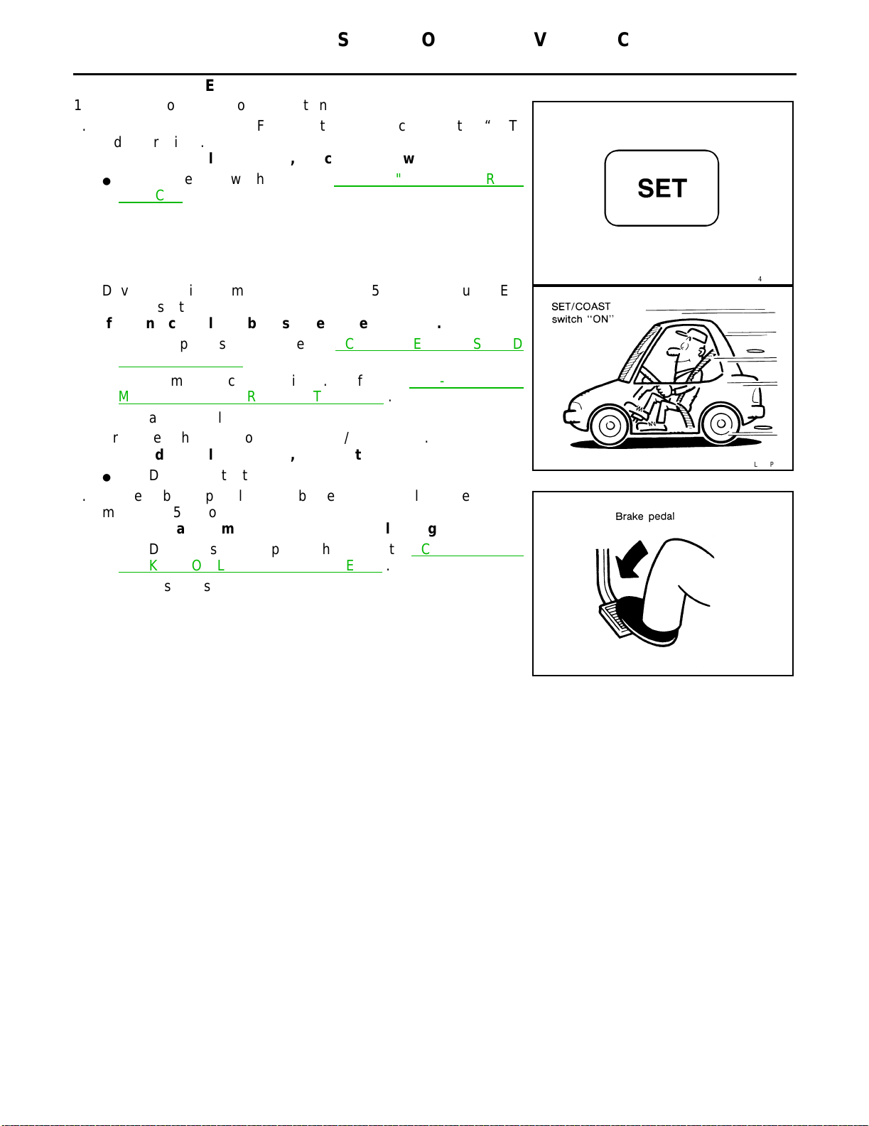
FAIL-SAFE SYSTEM CHECK
1. Turn ignition switch to ON position.
2. Turn CRUISE ON●OFF switch to ON and check if the “SET”
indicator blinks.
If the indicator lamp blinks, check the following.
● ASCD
steering switch. Refer to ACS-22, "ASCD STEERING
SWITCH" .
[QG18DE]
3. Drive the vehicle at more than 40 km/h (25 MPH) and push SET/
COAST switch.
If the indicator lamp blinks, check the following.
● Vehicle
speed sensor. Refer to ACS-19, "VEHICLE SPEED
SENSOR CHECK" .
● ASCD
motor actuator circuit. Refer to ACS-19, "ASCD
MOTOR ACTUATOR CIRCUIT CHECK" .
● Replace
control unit.
4. Drive the vehicle at more than 20 km/h (12 MPH).
If the indicator lamp blinks, replace the following.
● ASCD
motor actuator.
5. Depress brake pedal slowly (brake pedal should be depressed
more than 5 seconds).
If the indicator lamp blinks, check the following.
● ASCD
brake/stop lamp switch. Refer to ACS-16, "ASCD
BRAKE/STOP LAMP SWITCH CHECK" .
6. END. (System is OK.)
SEL417V
SEL767P
SAT797A
ACS-14
Page 33
AUTOMATIC SPEED CONTROL DEVICE (ASCD)
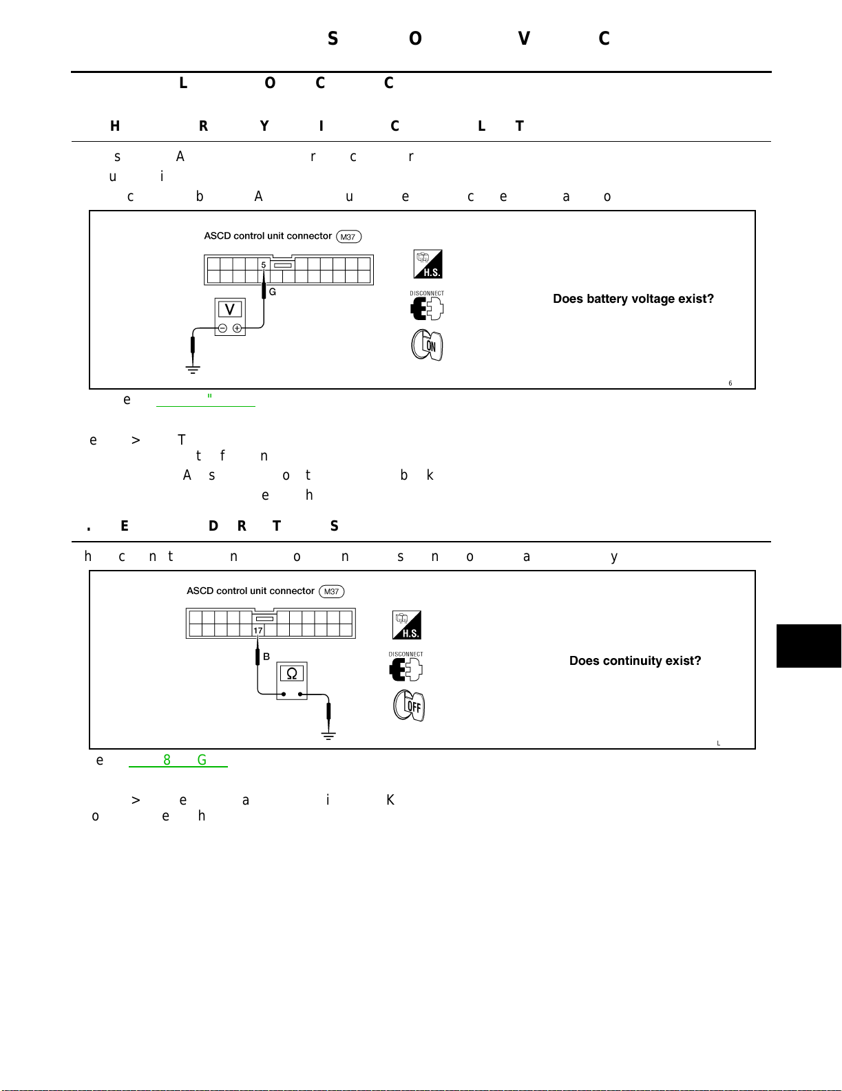
POWER SUPPLY AND GROUND CIRCUIT CHECK
1.
CHECK POWER SUPPLY CIRCUIT FOR ASCD CONTROL UNIT
[QG18DE]
A
1. Disconnec t ASCD control unit harness connector.
2. Turn ignition switch ON.
3. Check voltage between ASCD control unit harness connector terminal 5 and ground.
Refer to ACS-8, "
Yes >> GO TO 2.
No >> Check the following.
● 10A
● Harness
2.
CHECK GROUND CIRCUIT FOR ASCD CONTROL UNIT
Check continuity between ASCD control unit harness connector terminal 17 and body ground.
FIG. 1" .
fuse (No. 10 located in the fuse block)
for open or short
LEL516
B
C
D
E
F
G
H
I
Refer to ACS-8, "
Yes >> Power supply and ground circuit is OK.
No >> Repair harness.
FIG. 1" .
J
ACS
L
LEL517
M
ACS-15
Page 34
AUTOMATIC SPEED CONTROL DEVICE (ASCD)
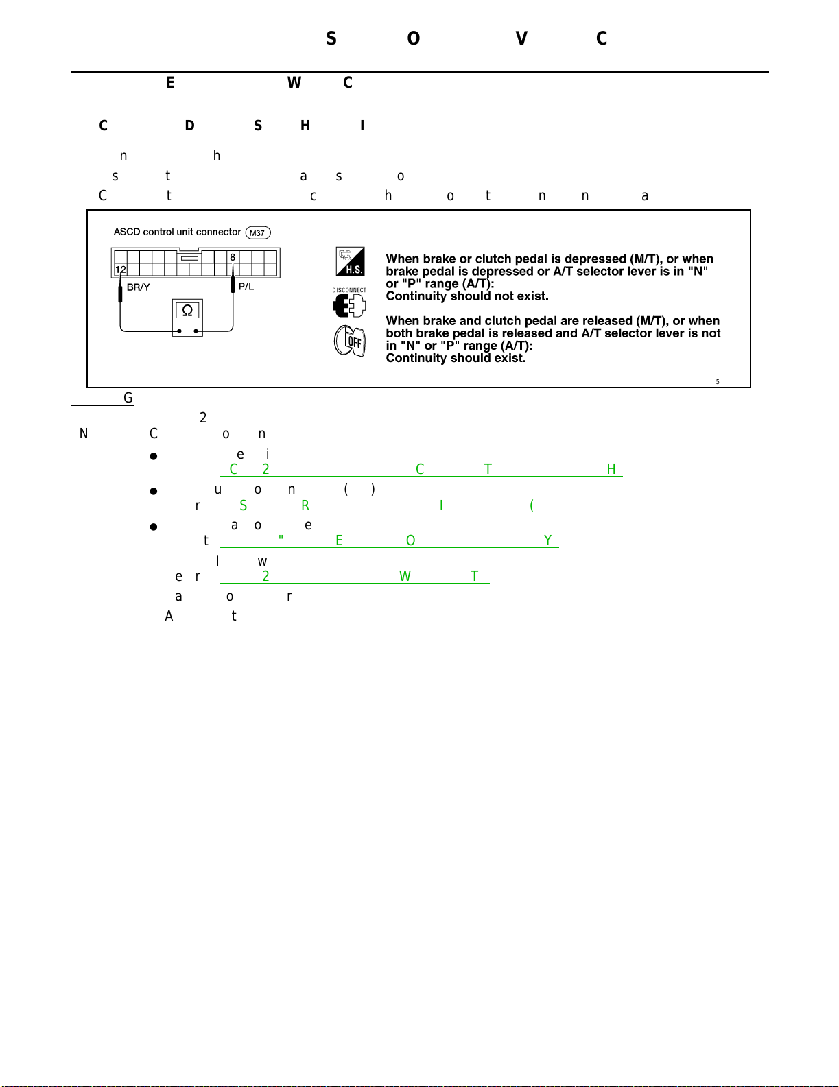
ASCD BRAKE/STOP LAMP SWITCH CHECK
1.
CHECK ASCD BRAKE SWITCH CIRCUIT
1. Turn ignition switch OFF.
2. Disconnect ASCD control unit harness connector.
3. Check continuity between ASCD control unit harness connector terminal 8 and terminal 12.
OK or NG
OK >> GO TO 2.
NG >> Check the following.
● ASCD
● Park/neutral
● Park/neutral
● ASCD
● Harness
● ASCD
brake switch
Refer to ACS-22, "
position switch (A/T)
Refer to ACS-22, "
position relay (A/T)
Refer to ACS-23, "
clutch switch (M/T)
Refer to ACS-22, "
for open or short
control unit
ASCD BRAKE SWITCH AND STOP LAMP SWITCH" .
PARK/NEUTRAL POSITION SWITCH (A/T)" .
PARK/NEUTRAL POSITON (PNP) RELAY" .
ASCD CLUTCH SWITCH (M/T)" .
[QG18DE]
LEL518
ACS-16
Page 35
AUTOMATIC SPEED CONTROL DEVICE (ASCD)
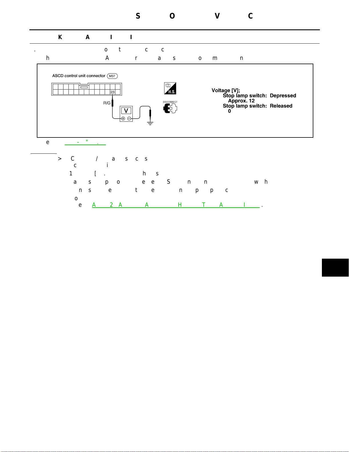
2.
CHECK STOP LAMP SWITCH CIRCUIT
1. Disconnec t ASCD control unit harness connector.
2. Check voltage between ASCD control unit harness connector terminal 23 and ground.
[QG18DE]
A
B
C
D
Refer to ACS-8, "
FIG. 1" .
OK or NG
OK >> ASCD brake/stop lamp switch is OK.
NG >> Check the following.
● 10A
fuse [No. 2, located in the fuse block (J/B)]
● Harness
● Harness
● Stop
Refer to ACS-22, "
for open or short between ASCD control unit and stop lamp switch
for open or short between fuse and stop lamp switch
lamp switch
ASCD BRAKE SWITCH AND STOP LAMP SWITCH" .
LEL519
E
F
G
H
I
J
ACS
L
ACS-17
M
Page 36
AUTOMATIC SPEED CONTROL DEVICE (ASCD)
ASCD STEERING SWITCH CHECK
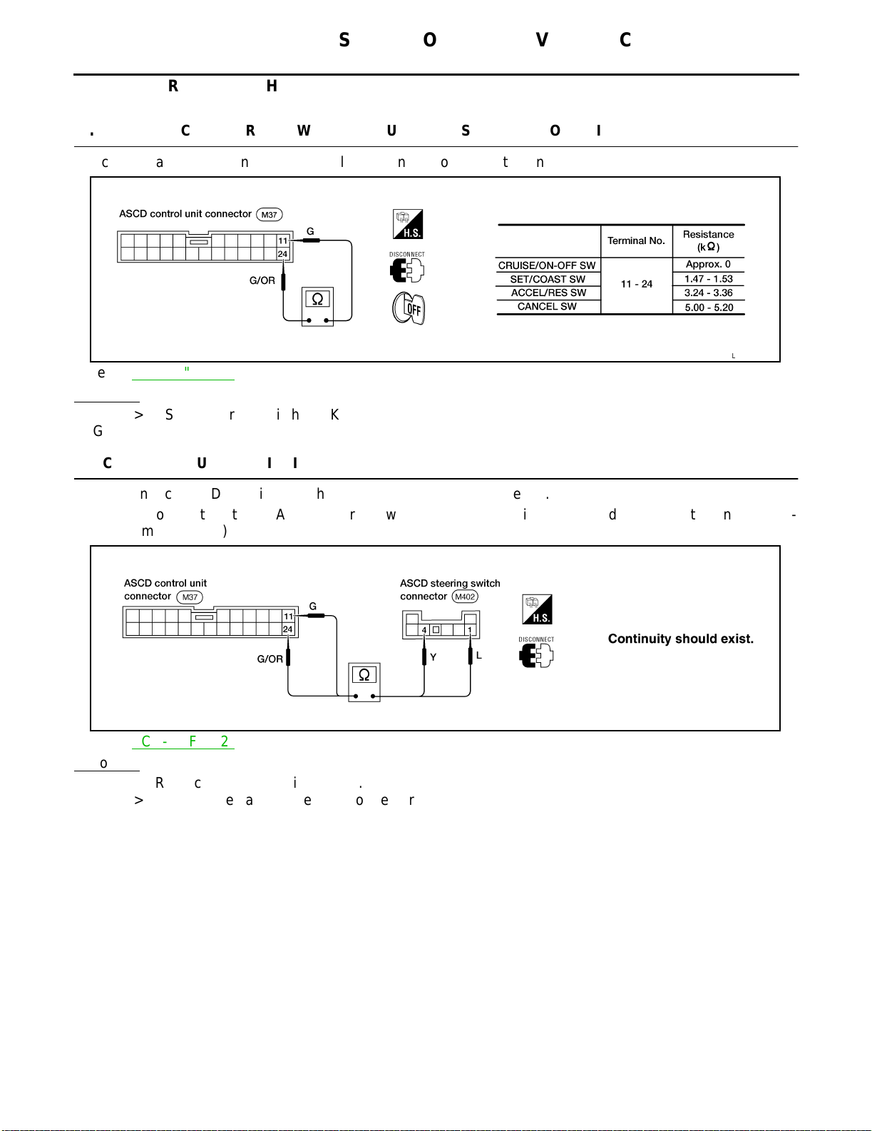
1.
CHECK ASCD STEERING SWITCH CIRCUIT FOR ASCD CONTROL UNIT
Check resistance between ASCD control unit harness connector terminals.
Refer to ACS-9, "
OK or NG
OK >> ASCD steering switch is OK.
NG >> GO TO 2.
FIG. 2" .
[QG18DE]
LEL520
2.
CHECK CIRCUIT CONTINUITY
1. Disconnect ASCD steering switch and ASCD control unit connector.
2. Check continuity between ASCD steering switch connector terminals 1 (4) and ASCD control unit connector terminal 24 (11).
LEL521
Refer to ACS-9, "
OK or NG
OK >> Replace ASCD steering switch.
NG >> Repair or replace harness or connectors.
FIG. 2" .
ACS-18
Page 37
AUTOMATIC SPEED CONTROL DEVICE (ASCD)
VEHICLE SPEED SENSOR CHECK
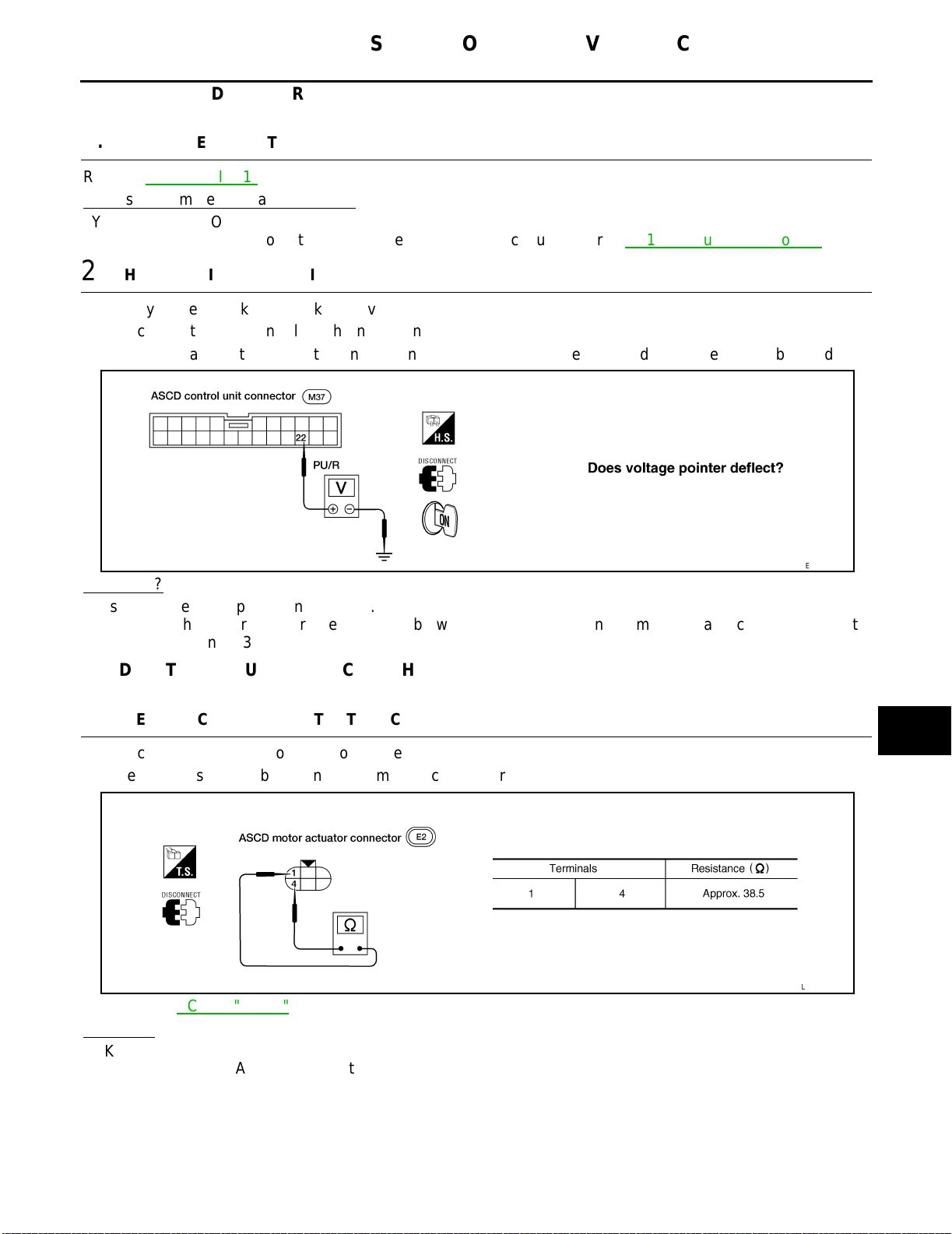
1.
CHECK SPEEDOMETER OPERATION
[QG18DE]
A
Refer to ACS-8, "
Does speedometer operate normally?
Yes >> GO TO 2.
No >> Check speedometer and vehicle speed sensor circuit. Refer to DI-15, "
2.
CHECK VEHICLE SPEED INPUT
1. Apply wheel chocks and jack up drive wheel.
2. Disconnec t ASCD control unit harness connector.
3. Check voltage between control unit terminal 22 and ground while turning drive wheel slowly by hand.
Yes or No?
Yes >> Vehicle speed sensor is OK.
No >> Check harness for open or short between ASCD control unit terminal 22 and combination meter
FIG. 1" .
Trouble Diagnoses" .
LEL522
terminal 13.
ASCD MOTOR ACTUATOR CIRCUIT CHECK
B
C
D
E
F
G
H
I
J
1.
CHECK ASCD MOTOR ACTUATOR (CLUTCH)
1. Disconnec t ASCD motor actuator connector.
2. Measure resistance between ASCD motor actuator terminals 1 and 4.
2"
Refer to ACS-9, "FIG.
OK or NG
OK >> GO TO 2.
NG >> Replace ASCD motor actuator.
.
ACS
L
M
LEL618
ACS-19
Page 38
AUTOMATIC SPEED CONTROL DEVICE (ASCD)
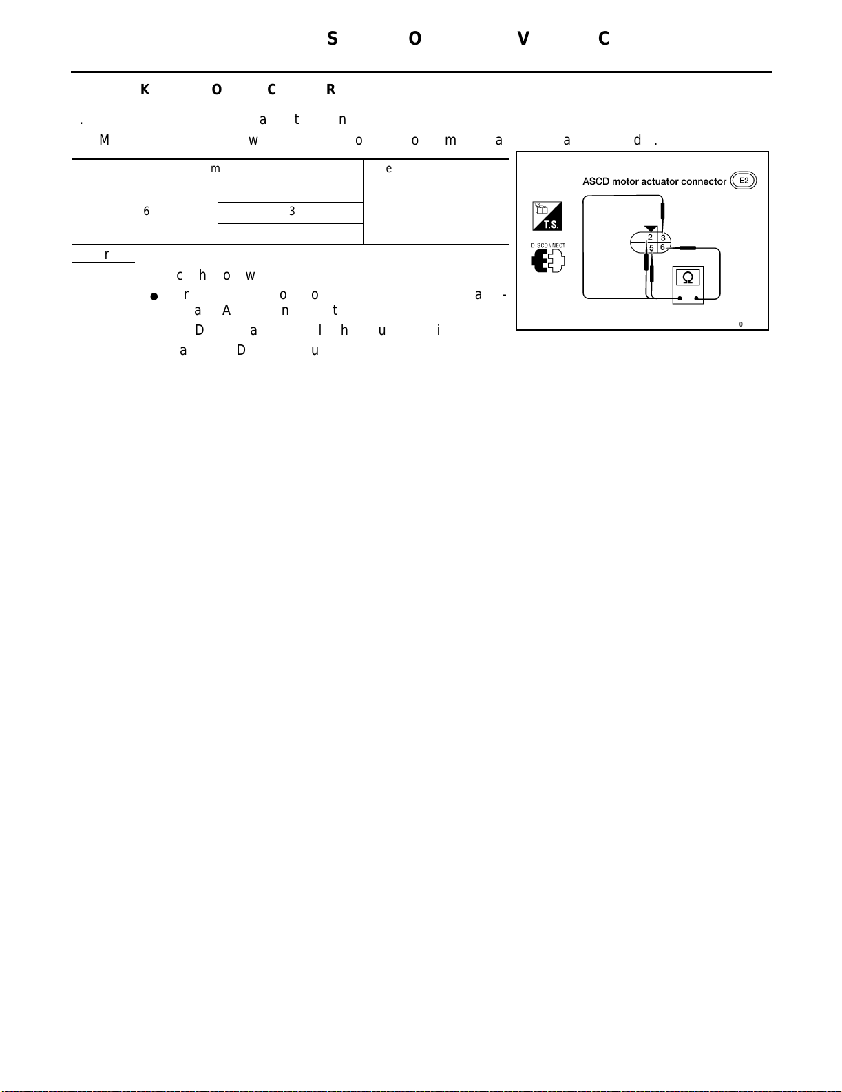
2.
CHECK ASCD MOTOR ACTUATOR (MOTOR)
1. Disconnect ASCD motor actuator connector.
2. Measure resistance between ASCD motor actuator terminal 6 and terminals 2, 3, and 5.
Terminals Resistance (Ω) Approx.
2
6
5
OK or NG
OK >> Check the following.
● Harness
ator and ASCD control unit
● ASCD
NG >> Replace ASCD motor actuator.
for open or short between ASCD motor actu-
motor actuator (clutch) ground circuit
5.23
[QG18DE]
WKIA0358E
ACS-20
Page 39
AUTOMATIC SPEED CONTROL DEVICE (ASCD)
ASCD MOTOR ACTUATOR CHECK
1.
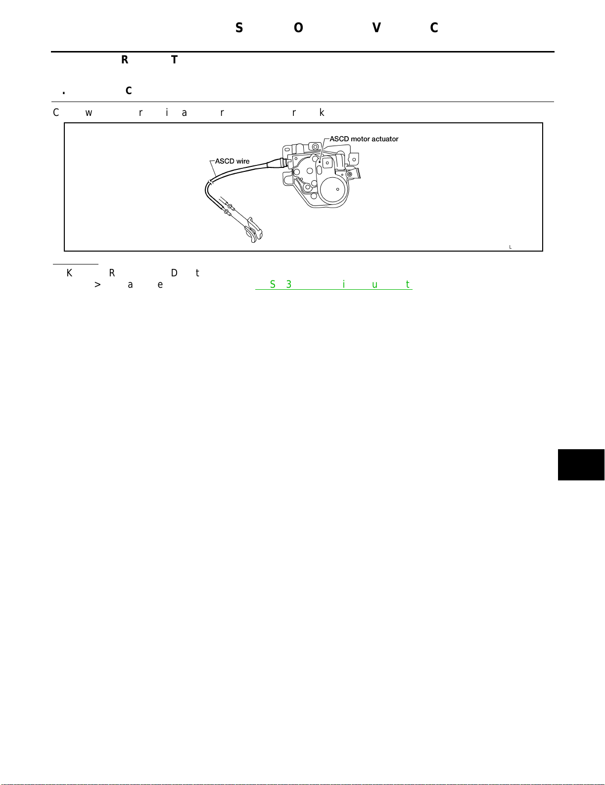
CHECK ASCD WIRE
[QG18DE]
A
Check wire for improper installation, rust formation or breaks.
OK or NG
OK >> Replace ASCD motor actuator.
NG >> Repair or replace wire. Refer to ACS-23, "
ASCD Wire Adjustment" .
B
C
D
E
LEL620
F
G
H
I
J
ACS
L
M
ACS-21
Page 40
AUTOMATIC SPEED CONTROL DEVICE (ASCD)
[QG18DE]
Electrical Component Inspection
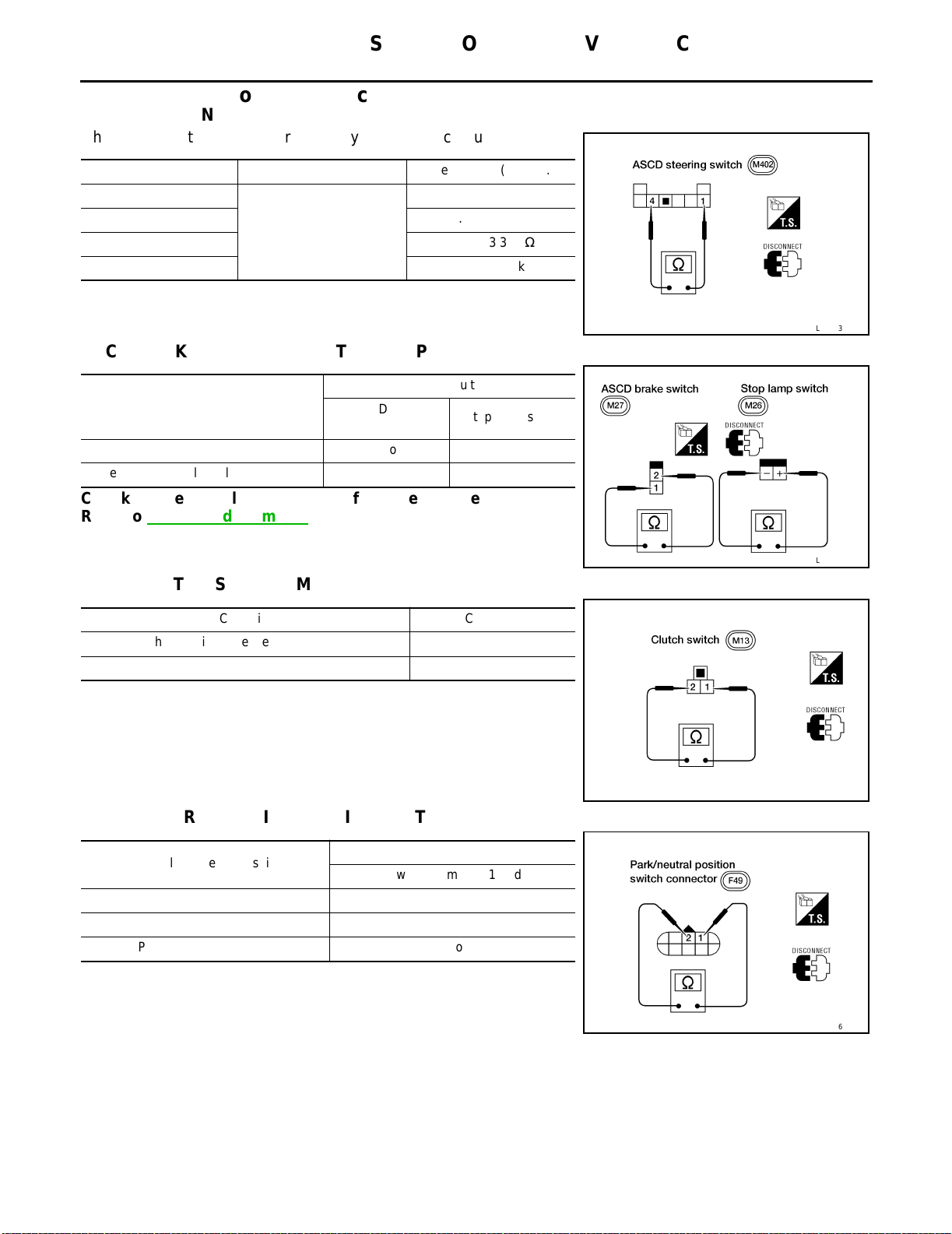
ASCD STEERING SWITCH
Check continuity between terminals by pushing each button.
Button Terminals Resistance (Approx.)
CRUISE/ON●OFF
SET/COAST 1.47 - 1.53 kΩ
ACCEL/RES 3.24 - 3.36 kΩ
CANCEL 5.00 - 5.20 kΩ
1 - 4
ASCD BRAKE SWITCH AND STOP LAMP SWITCH
Continuity
Condition
When brake pedal is depressed No Yes
When brake pedal is released Yes No
Check brake pedal adjustment after checking each switch.
Refer to BR-12, "
Adjustment" .
ASCD brake
switch
0 kΩ
Stop lamp switch
EKS002CQ
LEL523
ASCD CLUTCH SWITCH (M/T)
Condition Continuity
When clutch pedal is depressed No
When clutch pedal is released Yes
PARK/NEUTRAL POSITION SWITCH (A/T)
A/T selector lever position
“P” Yes
“N” Yes
Except “P” and “N” No
Between terminals 1 and 2
Continuity
LEL524
LEL525
ACS-22
LEL526
Page 41
AUTOMATIC SPEED CONTROL DEVICE (ASCD)
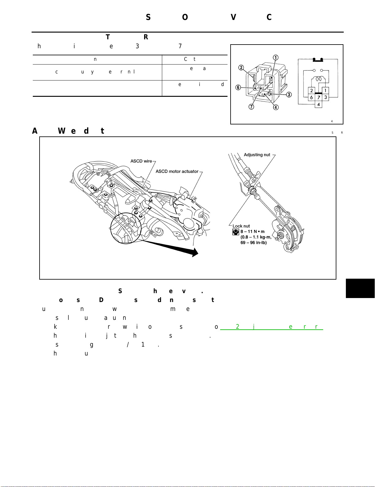
PARK/NEUTRAL POSITON (PNP) RELAY
Check continuity between terminals 3 and 4, 6 and 7.
Condition Continuity
12V direct current supply between terminals 1 and 2
No current supply
Between terminals 6 and
Between terminals 3 and
[QG18DE]
A
7
4
B
C
LEL644
ASCD Wire Adjustment EKS002CR
LEL569
CAUTION:
● Be
● Do
Adjust the tension of ASCD wire in the following manner.
1. Loosen lock nut and adjusting nut.
2. Make sure that accelerator wire is properly adjusted. Refer to ACC-2, "
3. Tighten adjusting nut just until throttle drum starts to move.
4. Loosen adjusting nut again 1/2 to 1 turn.
5. Tighten lock nut.
careful not to twist ASCD wire when removing it.
not tense ASCD wire excessively during adjustment.
Adjusting Accelerator Wire" .
D
E
F
G
H
I
J
ACS
L
M
ACS-23
Page 42
PRECAUTIONS
[QR25DE]
PRECAUTIONS
Precautions for Supplemental Restraint System (SRS) “AIR BAG” and “SEAT
BELT PRE-TENSIONER”
PFP:00001
EKS0043U
The Supplemental Restraint System such as “AIR BAG” and “SEAT BELT PRE-TENSIONER”, used along
with a front seat belt, helps to reduce the risk or severity of injury to the driver and front passenger for certain
types of collision. Information necessary to service the system safely is included in the SRS and SB section of
this Service Manual.
WARNING:
● To
avoid rendering the SRS inoperative, which could increase the risk of personal injury or death
in the event of a collision which would result in air bag inflation, all maintena nce must be performed by an authorized NISSAN/INFINITI dealer.
● Improper
maintenance, including incorrect removal and installation of the SRS, can lead to personal injury caused by unintentional activation of the system. For removal of Spiral Cable and Air
Bag Module, see the SRS section.
● Do
not use electrical test equipment on any circuit related to the SRS unless instructed to in this
Service Manual. SRS wiring harnesses can be identified by yellow and/or orange harness connectors.
Wiring Diagrams and T rouble Diagnosis EKS0043T
When you read wiring diagrams, refer to the following:
● GI-13,
● PG-2,
When you perform trouble diagnosis, refer to the following:
● GI-10,
● GI-26,
Check for any Service bulletins before servicing the vehicle.
"How to Read Wiring Diagrams"
"POWER SUPPLY ROUTING "
"HOW TO FOLLOW TEST GROUPS IN TROUBLE DIAGNOSES"
"How to Perform Efficient Diagnosis for an Electrical Incident"
ACS-24
Page 43
AUTOMATIC SPEED CONTROL DEVICE (ASCD)
[QR25DE]
AUTOMATIC SPEED CONTROL DEVICE (ASCD) PFP:18930
Description EKS002CS
Regarding the information for ASCD system, refer to EC-1850, "AUTOMATIC SPEED CONTROL DEVICE
(ASCD)" (QR25DE engine models).
A
B
C
D
E
F
G
H
I
J
ACS
L
M
ACS-25
Page 44

AUTOMATIC SPEED CONTROL DEVICE (ASCD)
[QR25DE]
ACS-26
Page 45
C TRANSMISSION/TRANSAXLE
A
B
SECTION
CONTENTS
RE4F03B
TROUBLE DIAGNOSIS - INDEX ................................ 7
Alphabetical & P No. Index for DTC ......................... 7
PRECAUTIONS .......................................................... 9
Precautions for Supplemental Re straint System
(SRS) “AIR BAG” and “SEAT BELT PRE-TEN-
SIONER” .................................................................. 9
Precautions for On Board Diagnostic (OBD) System
of A/T and Engine .................................................... 9
Precautions .............................................................. 9
Service Notice or Precautions .................................11
Wiring Diagrams and Trouble Diagnosis ................ 12
PREPARATION ........................ ............. .................... 13
Special Service Tools ............................................. 13
Commercial Service Tools ...................................... 16
OVERALL SYSTEM ................................................. 17
A/T Electrical Parts Location .................................. 17
Circuit Diagram ...................................................... 18
Cross-sectional View .............................................. 19
Hydraulic Control Circuit ........................................ 20
Shift Mechanism ..................................................... 21
Control System ... ...... ...... ....... ...... ....... ...... ....... ....... 30
Control Mechanism ......................................... ....... 31
Control Valve ............ ...... ....... ...... ........................... 35
ON BOARD DIAGNOSTIC SYSTEM DESCRIP-
TION ............................ .......................... .................... 37
Introduction ............................................................ 37
OBD-II Function for A/T System ............................. 37
One or Two Trip Detection Logic of OBD-II ............ 37
OBD-II Diagnostic Trouble Code (DTC) ................. 37
Malfunction Indicator Lamp (MIL) ........................... 41
CONSULT-II ........................................................... 41
TROUBLE DIAGNOSIS — INTRODUCTION ........... 56
Introduction ............................................................ 56
Work Flow .............................................................. 60
TROUBLE DIAGNOSIS — BASIC INSPECTION .... 63
A/T Fluid Check ...................................................... 63
Stall Test ................................................................. 63
Line Pressure Tes t ......... ....... ...... ....... .................... 67
Road Test ............................................................... 68
AUTOMATIC TRANSAXLE
TROUBLE DIAGNOSIS — GENERAL DESCRIP-
TION .......................................................................... 84
Symptom Chart ....................................................... 84
TCM Terminals and Reference Value ...................107
TROUBLE DIAGNOSIS FOR POWER SUPPLY .....111
Wiring Diagram — AT — MAIN .............................111
Diagnostic Procedure ...........................................112
DTC P0705 PARK/NEUTRAL POSITION (PNP)
SWITCH ..................................................................114
Description ................... ...... ....... ...... ......................114
Wiring Diagram — AT — PNP/SW .......................115
Diagnostic Procedure ...........................................116
Component Inspection ..........................................118
DTC P0710 A/T FLUID TEMPERATURE SENSOR
CIRCUIT ..................................................................119
Description ................... ...... ....... ...... ......................119
Wiring Diagram — AT — FTS ..............................120
Diagnostic Procedure ...........................................121
Component Inspection ..........................................123
DTC P0720 VEHICLE SPEED SENSOR·A/T (REV-
OLUTION SENSOR) ...............................................124
Description ................... ...... ....... ...... ......................124
Wiring Diagram — AT — VSSA/T ........................125
Diagnostic Procedure ...........................................126
DTC P0725 ENGINE SPEED SIGNAL ...................128
Description ................... ...... ....... ...... ......................128
Wiring Diagram — AT — ENGSS .........................129
Diagnostic Procedure ...........................................130
DTC P0731 A/T 1ST GEAR FUNCTION ................132
Description ................... ...... ....... ...... ......................132
Wiring Diagram — AT — 1ST ...............................134
Diagnostic Procedure ...........................................135
Component Inspection ..........................................136
DTC P0732 A/T 2ND GEAR FUNCTION ................137
Description ................... ...... ....... ...... ......................137
Wiring Diagram — AT — 2ND ..............................139
Diagnostic Procedure ...........................................140
Component Inspection ..........................................141
DTC P0733 A/T 3RD GEAR FUNCTION ................142
Description ................... ...... ....... ...... ......................142
AT
D
E
F
G
H
I
J
K
L
M
AT-1
Page 46

Wiring Diagram — AT — 3RD ..............................144
Diagnostic Procedure ...........................................145
Component Inspection ..........................................146
DTC P0734 A/T 4TH GEAR FUNCTION ................147
Description ................ .......................... ..................147
Wiring Diagram — AT — 4TH ...............................149
Diagnostic Procedure ...........................................150
Component Inspection ..........................................154
DTC P0740 TORQUE CONVERTER CLUTCH
SOLENOID VALVE .................. ...... ....... ...... ....... .....155
Description ................ .......................... ..................155
Wiring Diagram — AT — TCV ..............................156
Diagnostic Procedure ...........................................157
Component Inspection ..........................................158
DTC P0744 A/T TCC S/V FUNCTION (LOCK-UP) .160
Description ................ .......................... ..................160
Wiring Diagram — AT — TCCSIG ........................163
Diagnostic Procedure ...........................................164
Component Inspection ..........................................169
DTC P0745 LINE PRE SSU RE SO LENO ID VAL VE .170
Description ................ .......................... ..................170
Wiring Diagram — AT — LPSV ............................171
Diagnostic Procedure ...........................................172
Component Inspection ..........................................174
DTC P0750 SHIFT SOLENOID V ALVE A ...............176
Description ................ .......................... ..................176
Wiring Diagram — AT — SSV/A ...........................177
Diagnostic Procedure ...........................................178
Component Inspection ..........................................179
DTC P0755 SHIFT SOLENOID V ALVE B ...............180
Description ................ .......................... ..................180
Wiring Diagram — AT — SSV/B ...........................181
Diagnostic Procedure ...........................................182
Component Inspection ..........................................183
DTC P1705 THROTTLE POSITION SENSOR .......184
Description ................ .......................... ..................184
Wiring Diagram — AT — TPS ..............................186
Diagnostic Procedure ...........................................187
Component Inspection ..........................................191
DTC P1760 OVERRUN CLUTCH SOLENOID
VALVE .....................................................................192
Description ................ .......................... ..................192
Wiring Diagram — AT — OVRCSV ......................193
Diagnostic Procedure ...........................................194
Component Inspection ..........................................195
DTC BATT/FLUID TEMP SEN (A/T FLUID TEMP
SENSOR CIRCUIT AND TCM POWER SOURCE) .196
Description ................ .......................... ..................196
Wiring Diagram — AT — BA/FTS .........................198
Diagnostic Procedure ...........................................199
Component Inspection ..........................................201
DTC VHCL SPEED SEN·MTR VEHICLE SPEED
SENSOR·MTR ................... ......................................202
Description ................ .......................... ..................202
Wiring Diagram — AT — VSSMTR ......................204
Diagnostic Procedure ...........................................205
DTC CONTROL UNIT (RAM), CONTROL UNIT
(ROM) ......................................................................206
Description ............................................................206
Diagnostic Procedure ............................................206
DTC CONTROL UNIT (EEP ROM) .........................208
Description ............................................................208
Diagnostic Procedure ............................................209
TROUBLE DIAGNOSES FOR SYMPTOMS ...........210
Wiring Diagram — AT — NONDTC ......................210
1. O/D OFF Indicator Lamp Does Not Come On ..215
2. Engine Cannot Be Started In “P” and “N” Position .217
3. In “P” Position, Vehicle Moves Forward Or Back-
ward When Pushed ...............................................218
4. In “N” Position, Vehicle Moves ..........................219
5. Large Shock. “N” → “R” Position ......................221
6. Vehicle Does Not Creep Backward In “R” Position .222
7. Vehicle Does Not Creep Forward In “D”, “2” Or
“1” Position ............................................................224
8. Vehicle Cannot Be Started From D
9. A/T Does Not Shift: D
down: D
4 → D2 .....................................................229
10. A/T Does Not Shift: D
11. A/T Does Not Shift: D
1 → D2 Or Does Not Kick-
2 → D3 ..........................231
3 → D4 ...........................233
1 .................226
12. A/T Does Not Perform Lock-up .......................235
13. A/T Does Not Hold Lock-up Condition ............236
14. Lock-up Is Not Released .................................238
15. Engine Speed Does Not Return To Idle (Light
Braking D
16. Vehicle Does Not Start From D
17. A/T Does Not Shift: D
4 → D3 ) .................................................239
1 .....................240
4 → D3 , When Overdrive
Control Switch “ON” → “OFF” ... ............................242
18. A/T Does Not Shift: D
3 → 22 , When Selector
Lever “D” → “2” Position .......................................243
19. A/T Does Not Shift: 2
2 → 11 , When Selector
Lever “2” → “1” Position ........................................244
20. Vehicle Does Not Decelerate By Engine Brake .245
21. TCM Self-diagnosis Does Not Activate (PNP,
Overdrive Control and Throttle Position Switches
Circuit Checks) .................................................... ..245
A/T SHIFT LOCK SYSTEM .....................................253
Description ............................................................253
Shift Lock System Electrical Parts Location ..........253
Wiring Diagram — SHIFT — .................................254
Diagnostic Procedure ............................................255
KEY INTERLOCK CABLE ......................................259
Components ....................... .................... ...............259
Removal ............................. ...................................259
Installation .......................... ...................................260
ON-VEHICLE SERVICE ..........................................261
Control Valve Assembly and Accumulators ..........261
Control Cable Adjustment .....................................264
Park/Neutral Position (PNP) Switch Adjustment ...264
Differential Side Oil Seal Replacement .................265
Revolution Sensor Replacement ..........................265
REMOVAL AND INSTALLATION ............................266
Removal ............................. ...................................266
Installation .......................... ...................................267
OVERHAUL ................................. ............................269
Components ....................... .................... ...............269
Oil Channel ...........................................................272
AT-2
Page 47

Locations of Adjusting Shims, Needle Bearings,
Thrust Washers and Snap Rings ......................... 273
Disassembly ................... ...................................... 274
MANUAL SHAFT .................................................... 290
Components ................................ ......................... 290
Removal ............................................................... 290
Inspection ................. ............................................ 291
Installation ............................................................ 291
OIL PUMP ............................................................... 294
Components ................................ ......................... 294
Disassembly ................... ...................................... 294
Inspection ................. ............................................ 295
Assembly ........................ .................... .................. 297
CONTROL VALVE ASSEMBLY ............................. 299
Components ................................ ......................... 300
Disassembly ................... ...................................... 301
Inspection ................. ............................................ 304
Assembly ........................ .................... .................. 305
CONTROL VALVE UPPER BODY ......................... 310
Components ................................ ..........................311
Disassembly ................... .......................................311
Inspection ................. ............................................ 312
Assembly ........................ .................... .................. 313
CONTROL VALVE LOWER BODY ........................ 315
Components ................................ ......................... 316
Disassembly ................... ...................................... 316
Inspection ................. ............................................ 317
Assembly ........................ .................... .................. 317
REVERSE CLUTCH ............................................... 318
Components ................................ ......................... 319
Disassembly ................... ...................................... 319
Inspection ................. ............................................ 320
Assembly ........................ .................... .................. 321
HIGH CLUTCH ....................................................... 324
Components ................................ ......................... 325
Disassembly ................... ...................................... 325
Inspection ................. ............................................ 327
Assembly ........................ .................... .................. 327
FORWARD CLUTCH AND OVERRUN CLUTCH .. 330
Components ................................ ......................... 330
Disassembly ................... ...................................... 330
Inspection ................. ............................................ 332
Assembly ........................ .................... .................. 334
LOW & REVERSE BRAKE .................................... 338
Components ................................ ......................... 339
Disassembly ................... ...................................... 339
Inspection ................. ............................................ 340
Assembly ........................ .................... .................. 341
REAR INTERNAL GEAR, FORWARD CLUTCH
HUB AND OVERRUN CLUTCH HUB .................... 344
Components ................................ ......................... 344
Disassembly ................... ...................................... 344
Inspection ................. ............................................ 346
Assembly ........................ .................... .................. 346
OUTPUT SHAFT , IDLER GEAR, REDUCTION PIN-
ION GEAR AND BEARING RETAINER ................. 349
Components ................................ ......................... 349
Disassembly ................... ...................................... 349
Inspection .............................................................351
Assembly ..................... .........................................352
BAND SERVO PISTON ASSEMBLY ......................355
Components .........................................................355
Disassembly .........................................................355
Inspection .............................................................358
Assembly ..................... .........................................358
FINAL DRIVE ........................................... ...... ....... ..362
Components .........................................................362
Disassembly .........................................................362
Inspection .............................................................364
Assembly ..................... .........................................364
ASSEMBLY ....................................... ......................367
Assembly (1) .........................................................367
Adjustment (1) ......................................................368
Assembly (2) .........................................................375
Adjustment (2) ......................................................379
Assembly (3) .........................................................383
Assembly (4) .........................................................386
SERVICE DATA AND SPECIFICATIONS (SDS) ....392
General Specifications . ...... ....... ...... ......................392
Shift Schedule ......................................................392
Stall Revolution .....................................................392
Line Pressure .......................................................393
Control Valves ......................................................393
Clutch, Brake and Brake Band .............................393
Clutch and Brake Return Springs .........................395
Oil Pump ...............................................................395
Input Shaft ................... ...... ....... ...... ......................395
Planetary Carrier ..................................................396
Final Drive ............................................................396
Reduction Pinion Gear .........................................397
Output Shaft .........................................................399
Bearing Retainer ...................................................399
Total End Play .......................................................400
Reverse Clutch End Play ......................................400
Accumulator ................. ...... ....... ............................400
Band Servo ...........................................................400
Removal and Installation ......................................400
Shift Solenoid Valves ............................................401
Solenoid Valve ......................................................401
A/T Fluid Temperature Sensor ..............................401
Revolution Sensor ................................................401
Dropping Resistor .................................................401
RE4F04B
TROUBLE DIAGNOSIS - INDEX ............................402
Alphabetical & P No. Index for DTC .....................402
PRECAUTIONS ......................................................404
Precautions for Supplemental Restraint System
(SRS) “AIR BAG” and “SEAT BELT PRE-TEN-
SIONER” ...................... ...... ....... ...... ....... ...... .........404
Precautions for On Board Diagnostic (OBD) System
of A/T and Engine .................................................404
Precautions .................. ...... ....... ...... ....... ...... ....... ..404
Service Notice or Precautions ..............................406
Wiring Diagrams and Trouble Diagnosis ..............407
A
B
AT
D
E
F
G
H
I
J
K
L
M
AT-3
Page 48

PREPARATION .......................................................408
Special Service Tools .................. ....... ...... ....... .....408
Commercial Service Tools .................. ...... ............410
OVERALL SYSTEM .............................. ...... ....... .....412
A/T Electrical Parts Location .................................412
Circuit Diagram .....................................................413
Cross-sectional View ............................................414
Hydraulic Control Circuit .......................................415
Shift Mechanism ...................................................416
Control System .....................................................425
Control Mechanism ...............................................427
Control Valve ........................................................431
ON BOARD DIAGNOSTIC SYSTEM DESCRIP-
TION ........................................................................433
Introduction ............... ............................................433
OBD-II Function for A/T System ...........................433
One or Two Trip Detection Logic of OBD-II ..........433
OBD-II Diagnostic Trouble Code (DTC) ...............433
Malfunction Indicator Lamp (MIL) .........................437
CONSULT-II ........ ...................................... ............437
Diagnostic Procedure Without CONSULT-II .........446
TROUBLE DIAGNOSIS - INTRODUCTION ...........451
Introduction ............... ............................................451
Work Flow .............................................................455
TROUBLE DIAGNOSIS - BASIC INSPECTION .....458
A/T Fluid Check ....................................................458
Stall Test ...............................................................458
Line Pressure Test ................................................462
Road Test .... ....... ...... ...... ......................................463
TROUBLE DIAGNOSIS - GENERAL DESCRIP-
TION ........................................................................479
Symptom Chart .....................................................479
TCM Terminals and Reference Value ...................489
System Description ...............................................492
TROUBLE DIAGNOSIS FOR POWER SUPPLY ....493
Wiring Diagram — AT — MAIN ............................493
Diagnostic Procedure ...........................................494
DTC P0705 PARK/NEUTRAL POSITION SWITCH .496
Description ................ .......................... ..................496
On Board Diagnosis Logic ....................................496
Possible Cause .....................................................496
Diagnostic Trouble Code (DTC) Confirmation Pro-
cedure ....................... .......................... ..................496
Wiring Diagram — AT — PNP/SW .......................498
Diagnostic Procedure ...........................................499
DTC P0710 A/T FLU ID T EMPE RATURE SENSOR
CIRCUIT ..................................................................502
Description ................ .......................... ..................502
On Board Diagnosis Logic ....................................502
Possible Cause .....................................................502
Diagnostic Trouble Code (DTC) Confirmation Pro-
cedure ....................... .......................... ..................502
Wiring Diagram — AT — FTS ...............................504
Diagnostic Procedure ...........................................506
DTC P0720 VEHI CLE SPEED SENSOR ·A/T (REV -
OLUTION SENSOR) ...............................................509
Description ................ .......................... ..................509
On Board Diagnosis Logic ....................................509
Possible Cause .....................................................509
Diagnostic Trouble Code (DTC) Confirmation Pro-
cedure ...................................................................509
Wiring Diagram — AT — VSSA/T .........................511
Diagnostic Procedure ............................................512
DTC P0725 ENGINE SPEED SIGNAL ....................514
Description ............................................................514
On Board Diagnosis Logic ....................................514
Possible Cause .....................................................514
Diagnostic Trouble Code (DTC) Confirmation Pro-
cedure ...................................................................514
Wiring Diagram — AT — ENGSS .........................515
Diagnostic Procedure ............................................516
DTC P0731 A/T 1ST GEAR FUNCTION .................518
Description ............................................................518
On Board Diagnosis Logic ....................................518
Possible Cause .....................................................518
Diagnostic Trouble Code (DTC) Confirmation Pro-
cedure ...................................................................518
Wiring Diagram — AT — 1ST ...............................520
Diagnostic Procedure ............................................521
DTC P0732 A/T 2ND GEAR FUNCTION ................523
Description ............................................................523
On Board Diagnosis Logic ....................................523
Possible Cause .....................................................523
Diagnostic Trouble Code (DTC) Confirmation Pro-
cedure ...................................................................523
Wiring Diagram — AT — 2ND ..............................525
Diagnostic Procedure ............................................526
DTC P0733 A/T 3RD GEAR FUNCTION ................528
Description ............................................................528
On Board Diagnosis Logic ....................................528
Possible Cause .....................................................528
Diagnostic Trouble Code (DTC) Confirmation Pro-
cedure ...................................................................528
Wiring Diagram — AT — 3RD ..............................530
Diagnostic Procedure ............................................531
DTC P0734 A/T 4TH GEAR FUNCTION .................533
Description ............................................................533
On Board Diagnosis Logic ....................................533
Possible Cause .....................................................533
Diagnostic Trouble Code (DTC) Confirmation Pro-
cedure ...................................................................533
Wiring Diagram — AT — 4TH ...............................535
Diagnostic Procedure ............................................536
DTC P0740 TORQUE CONVERTER CLUTCH
SOLENOID VALVE ..................................................540
Description ............................................................540
On Board Diagnosis Logic ....................................540
Possible Cause .....................................................540
Diagnostic Trouble Code (DTC) Confirmation Pro-
cedure ...................................................................540
Wiring Diagram — AT — TCV ..............................542
Diagnostic Procedure ............................................543
DTC P0744 A/T TCC S/V FUNCTION (LOCK-UP) .545
Description ............................................................545
On Board Diagnosis Logic ....................................545
Possible Cause .....................................................545
Diagnostic Trouble Code (DTC) Confirmation Pro-
cedure ...................................................................545
AT-4
Page 49

Wiring Diagram — AT — TCCSIG ....................... 547
Diagnostic Procedure ........................................... 548
DTC P0745 LINE PRESSURE SOLENOID VALVE . 553
Description ........................................................... 553
On Board Diagnosis Logic ................................... 553
Possible Cause .................................................... 553
Diagnostic Trouble Code (DTC) Confirmation Pro-
cedure .................................................................. 553
Wiring Diagram — AT — LPSV ............................ 555
Diagnostic Procedure ........................................... 556
DTC P0750 SHIFT SOLENOID VALVE A .............. 559
Description ........................................................... 559
On Board Diagnosis Logic ................................... 559
Possible Cause .................................................... 559
Diagnostic Trouble Code (DTC) Confirmation Pro-
cedure .................................................................. 559
Wiring Diagram — AT — SSV/A .......................... 561
Diagnostic Procedure ........................................... 562
DTC P0755 SHIFT SOLENOID VALVE B .............. 564
Description ........................................................... 564
On Board Diagnosis Logic ................................... 564
Possible Cause .................................................... 564
Diagnostic Trouble Code (DTC) Confirmation Pro-
cedure .................................................................. 564
Wiring Diagram — AT — SSV/B .......................... 566
Diagnostic Procedure ........................................... 567
DTC P1705 THROTTLE POSITION SENSOR
[ACCELERATOR PEDAL POSITION (APP) SEN-
SOR] ....................................................................... 569
Description ........................................................... 569
On Board Diagnosis Logic ................................... 570
Possible Cause .................................................... 570
Diagnostic Trouble Code (DTC) Confirmation Pro-
cedure .................................................................. 570
Wiring Diagram — AT — TPS .............................. 572
Diagnostic Procedure ........................................... 573
DTC P1760 OVERRUN CLUTCH SOLENOID
VALVE ......................... ............................................ 575
Description ........................................................... 575
On Board Diagnosis Logic ................................... 575
Possible Cause .................................................... 575
Diagnostic Trouble Code (DTC) Confirmation Pro-
cedure .................................................................. 575
Wiring Diagram — AT — OVRCSV ...................... 577
Diagnostic Procedure ........................................... 578
DTC BATT/FLUID TEMP SEN (A/T FLUID TEMP
SENSOR CIRCUIT AND TCM POWER SOURCE) . 580
Description ........................................................... 580
On Board Diagnosis Logic ................................... 580
Possible Cause .................................................... 580
Diagnostic Trouble Code (DTC) Confirmation Pro-
cedure .................................................................. 580
Wiring Diagram — AT — BA/FTS ........................ 582
Diagnostic Procedure ........................................... 583
DTC VEHICLE SPEED SENSOR MTR .................. 587
Description ........................................................... 587
On Board Diagnosis Logic ................................... 587
Possible Cause .................................................... 587
Diagnostic Trouble Code (DTC) Confirmation Pro-
cedure .......................... ...... ....... ...... ....... ...... ....... ..587
Wiring Diagram — AT — VSSMTR ......................589
Diagnostic Procedure ...........................................590
DTC TURBINE REVOLUTION SENSOR ...............592
Description ................... ...... ....... ...... ......................592
Wiring Diagram — AT — TRSA/T ........................594
Diagnostic Procedure ...........................................595
Component Inspection ..........................................596
DTC U1000 CAN COMMUNICATION LINE ............597
Description ................... ...... ....... ...... ......................597
On Board Diagnosis Logic ....................................597
Possible Cause .....................................................597
DTC Confirmation Procedure ...............................597
Wiring Diagram — AT — CAN ..............................598
Diagnostic Procedure ...........................................599
DTC CONTROL UNIT (RAM), CONTROL UNIT
(ROM) ............................. ....................................... ..600
Description ................... ...... ....... ...... ......................600
On Board Diagnosis Logic ....................................600
Possible Cause .....................................................600
Diagnostic Trouble Code (DTC) Confirmation Pro-
cedure .......................... ...... ....... ...... ....... ...... ....... ..600
Diagnostic Procedure ...........................................601
DTC CONTROL UNIT (EEP ROM) ... ....... ...... ....... ..602
Description ................... ...... ....... ...... ......................602
Diagnostic Procedure ...........................................603
TROUBLE DIAGNOSIS FOR SYMPTOMS ... ....... ..604
Wiring Diagram — AT — NONDTC ......................604
1. O/D OFF Indicator Lamp Does Not Come On ..609
2. Engine Cannot Be Started In P and N Position .611
3. In P Position, Vehicle Moves Forward or Back-
ward When Pushed ..............................................612
4. In N Position, Vehicle Moves ............................613
5. Large Shock N → R Position ............................615
6. Vehicle Does Not Creep Backward In R Position .617
7. Vehicle Does Not Creep Forward in D, 2 or 1 Posi-
tion ........................ ................................. ...............620
8. Vehicle Cannot Be Started From D
9. A/T Does Not Shift: D
down: D
4 → D2 ......................... ............................626
10. A/T Does Not Shift: D
11. A/T Does Not Shift: D
1 → D2 or Does Not Kick-
2 → D3 ........................ ..629
3 → D4 ..........................632
1 .................623
12. A/T Does Not Perform Lock-up ......................635
13. A/T Does Not Hold Lock-up Condition ............637
14. Lock-up Is Not Released ................................639
15. Engine Speed Does Not Return To Idle (Light
Braking D
16. Vehicle Does Not Start From D
17. A/T Does Not Shift: D
4 → D3 ) ................................................640
1 .....................642
4 → D3 , When Overdrive
Control Switch ON → OFF ...................................643
18. A/T Does Not Shift: D
3 → 22 , When Selector
Lever D → 2 Position ............................................644
19. A/T Does Not Shift: 2
2 → 11 , When Selector
Lever 2 → 1 Position ............................................645
20. Vehicle Does Not Decelerate By Engine Brake .646
21. TCM Self-diagnosis Does Not Activate {Park/
neutral Position (PNP), Overdrive Control and
Throttle Position Sensor [Accelerator Pedal Posi-
tion (APP) Sensor] Switches Circuit Checks} .......646
A
B
AT
D
E
F
G
H
I
J
K
L
M
AT-5
Page 50

A/T SHIFT LOCK SYSTEM ................................ .....651
Description ................ .......................... ..................651
Shift Lock System Electrical Parts Location .........651
Wiring Diagram — SHIFT — ................................652
Diagnostic Procedure ...........................................653
KEY INTERLOCK CABLE ......................................657
Components .........................................................657
Removal ...............................................................657
Installation .............................. ...... ....... ..................658
ON-VEHICLE SERVICE ..........................................659
Control Valve Assembly and Accumulators ..........659
Revolution Sensor Replacement ..........................661
Park/Neutral Position (PNP) Switch Adjustment ...661
Control Cable Adjustment .....................................662
Differential Side Oil Seal Replacement .................662
REMOVAL AND INSTALLATION ...........................664
Removal ...............................................................664
Installation .............................. ...... ....... ..................665
OVERHAUL ....................... ....... ...... ....... ...... ....... .....667
Components .........................................................667
Oil Channel ...........................................................670
Locations of Adjusting Shims, Needle Bearings,
Thrust Washers and Snap Rings ..........................671
DISASSEMBLY .......................................................672
Disassembly .........................................................672
REPAIR FOR COMPONENT PARTS ......................687
Manual Shaft ............ ...... ....... ...............................687
Oil Pump ...............................................................690
Control Valve Assembly ........................................694
Control Valve Upper Body ....................................702
Control Valve Lower Body ....................................706
Reverse Clutch ...................... ...... ....... ...... ............709
High Clutch ...........................................................712
Forward And Overrun Clutches ............................717
Low & Reverse Brake ...........................................723
Rear Internal Gear, Forward Clutch Hub and Over-
run Clutch Hub ......................................................725
Output Shaft, Idler Gear, Reduction Pinion Gear and
Bearing Retainer .................................... ...... ....... ..729
Band Servo Piston Assembly ................................734
Final Drive .............................................................739
ASSEMBLY .............................................................744
Assembly (1) .......................................... ...... ....... ..744
Adjustment (1) .......................................................745
Assembly (2) .......................................... ...... ....... ..750
Adjustment (2) .......................................................757
Assembly (3) .......................................... ...... ....... ..759
SERVICE DATA AND SPECIFICATIONS (SDS) ....766
General Specifications ..........................................766
Shift Schedule .......................................................766
Stall Revolution .....................................................766
Line Pressure ........................................................767
Control Valves .......................................................767
Accumulator ..........................................................767
Clutch and Brakes ........ ...... ....... ...... ......................768
Final Drive .............................................................770
Planetary Carrier and Oil Pump ............................770
Input Shaft .............................................................771
Reduction Pinion Gear ....... ....... ...... ....... ...............771
Band Servo ...........................................................772
Output Shaft ....................... ....... ...... ....... ...... ....... ..772
Bearing Retainer .................................... ...... ....... ..773
Total End Play .......................................................773
Reverse Clutch End Play ......................................773
Removal and Installation .......................................773
Shift Solenoid Valves ............................................774
Solenoid Valves ....................................................774
A/T Fluid Temperature Sensor ..............................774
Revolution Sensor .................................................774
Dropping Resistor .................................................774
Turbine Revolution Sensor ....................................774
AT-6
Page 51
TROUBLE DIAGNOSIS - INDEX
[RE4F03B]
TROUBLE DIAGNOSIS - INDEX PFP:00000
Alphabetical & P No. Index for DTC ECS004CK
ALPHABETICAL INDEX FOR DTC
Items
(CONSULT-II screen terms)
A/T 1ST GR FNCTN P0731
A/T 2ND GR FNCTN P0732
A/T 3RD GR FNCTN P0733
A/T 4TH GR FNCTN P0734
A/T TCC S/V FNCTN P0744
ATF TEMP SEN/CIRC P0710
ENGINE SPEED SIG P0725
L/PRESS SOL/CIRC P0745
O/R CLTCH SOL/CIRC P1760
PNP SW/CIRC P0705
SFT SOL A/CIRC*2 P0750
SFT SOL B/CIRC*2 P0755
TCC SOLENOID/CIRC P0740
TP SEN/CIRC A/T*2 P1705
VEH SPD SEN/CIR AT*3 P0720
● *1: These numbers are prescribed by SAE J2012.
● *2: When the fail-safe operation occurs , the MIL illu m inat es.
● *3: The MIL illuminates when both the “Revolution sensor signal” and the “Vehicle speed sensor signal” meet the fail-safe condition at
the same time.
DTC
CONSULT-II
GST*1
Reference page
AT-132, "
AT-137, "
AT-142, "
AT-147, "
AT-160, "
S/V FUNCTION (LOCK-UP)"
AT -1 19, "
AT-128, "
AT-192, "
AT-114, "
NEUTRAL POSITION (PNP)
AT-176, "
AT-180, "
AT-155, "
CONVERTER CLUTCH SOLE-
AT-184, "
AT-124, "
SPEED SENSOR·A/T (REVO-
DTC P0731 A/T 1ST
GEAR FUNCTION"
DTC P0732 A/T 2ND
GEAR FUNCTION"
DTC P0733 A/T 3RD
GEAR FUNCTION"
DTC P0734 A/T 4TH
GEAR FUNCTION"
DTC P0744 A/T TCC
DTC P0710 A/T FLUID
TEMPERATURE SENSOR
CIRCUIT"
DTC P0725 ENGINE
SPEED SIGNAL"
AT-170, "
PRESSURE SOLENOID
RUN CLUTCH SOLENOID
TLE POSITION SENSOR"
DTC P0745 LINE
VALVE"
DTC P1760 OVER-
VALVE"
DTC P0705 PARK/
SWITCH"
DTC P0750 SHIFT
SOLENOID VALVE A"
DTC P0755 SHIFT
SOLENOID VALVE B"
DTC P0740 TORQUE
NOID VALVE"
DTC P1705 THROT-
DTC P0720 VEHICLE
LUTION SENSOR)"
A
B
AT
D
E
F
G
H
I
J
K
L
M
AT-7
Page 52
P NO. INDEX FOR DTC
DTC
CONSULT-II
GST*1
P0705 PNP SW/CIRC
P0710 ATF TEMP SEN/CIRC
P0720 VEH SPD SEN/CIR AT*3
P0725 ENGINE SPEED SIG
P0731 A/T 1ST GR FNCTN
P0732 A/T 2ND GR FNCTN
P0733 A/T 3RD GR FNCTN
P0734 A/T 4TH GR FNCTN
P0740 TCC SOLENOID/CIRC
P0744 A/T TCC S/V FNCTN
P0745 L/PRESS SOL/CIRC
P0750 SFT SOL A/CIRC*2
P0755 SFT SOL B/CIRC*2
P1705 TP SEN/CIRC A/T*2
P1760 O/R CLTCH SOL/CIRC
TROUBLE DIAGNOSIS - INDEX
Items
(CONSULT-II screen terms)
[RE4F03B]
Reference page
AT-114, "
NEUTRAL POSITION (PNP)
AT-119, "
TEMPERATURE SENSOR
AT-124, "
SPEED SENSOR·A/T (REVO-
AT-128, "
AT-132, "
AT-137, "
AT-142, "
AT-147, "
AT-155, "
CONVERTER CLUTCH SOLE-
AT-160, "
S/V FUNCTION (LOCK-UP)"
AT-170, "
AT-176, "
AT-180, "
AT-184, "
TLE POSITION SENSOR"
AT-192, "
RUN CLUTCH SOLENOID
DTC P0705 PARK/
SWITCH"
DTC P0710 A/T FLUID
CIRCUIT"
DTC P0720 VEHICLE
LUTION SENSOR)"
DTC P0725 ENGINE
SPEED SIGNAL"
DTC P0731 A/T 1ST
GEAR FUNCTION"
DTC P0732 A/T 2ND
GEAR FUNCTION"
DTC P0733 A/T 3RD
GEAR FUNCTION"
DTC P0734 A/T 4TH
GEAR FUNCTION"
DTC P0740 TORQUE
NOID VALVE"
DTC P0744 A/T TCC
DTC P0745 LINE
PRESSURE SOLENOID
VALVE"
DTC P0750 SHIFT
SOLENOID VALVE A"
DTC P0755 SHIFT
SOLENOID VALVE B"
DTC P1705 THROT-
DTC P1760 OVER-
VALVE"
● *1: These numbers are prescribed by SAE J2012.
● *2: When the fail-safe operation occurs, the MIL illumi nat es.
● *3: The MIL illuminates when both the “Revolution sensor signal” and the “Vehicle speed sensor signal” meet the fail-safe condition at
the same time.
AT-8
Page 53
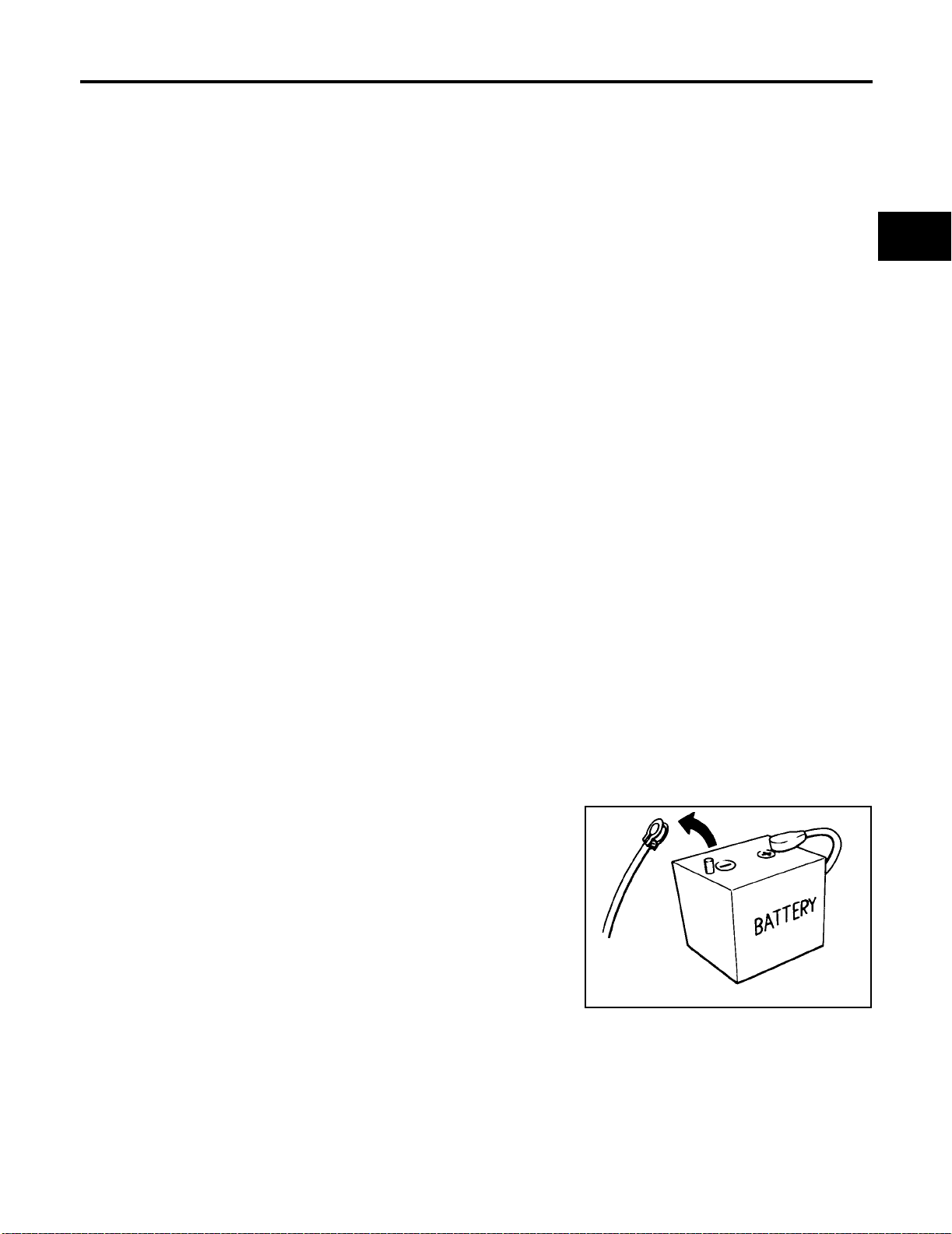
PRECAUTIONS
[RE4F03B]
PRECAUTIONS PFP:00001
Precautions for Supplemental Restraint System (SRS) “AIR BAG” and “SEAT
BELT PRE-TENSIONER”
ECS004CL
A
The Supplemental Rest raint System such as “AIR BAG” and “SEAT BELT PR E-TENSIONER”, used along
with a front seat belt, helps to reduce the risk or severity of injury to the driver and front passenger for certain
types of col lision. Infor mation necess ary to service the system safely is included in the S RS and SB sect ion of
this Service Manual.
WARNING:
● To avoid rendering the SRS inopera tive, which c ould increa se the risk of perso nal injury or dea th
in the event of a collision which would result in air bag inflation, all maintenance must be performed by an authorized NISSAN/INFINITI dealer.
● Improper maintenance, inc luding incorrect removal and installation of the SRS, can lead to per-
sonal injury ca use d by unintentional ac tiv atio n o f the s yst em . F or re moval of Spiral Cable and Air
Bag Module, see the SRS section.
● Do not use electrical test equ ipment o n any circu it related to the SRS unless in structed to in this
Service Manual. SRS wiring harnesses can be identified by yellow and/or orange harnesses or
harness connectors.
Precautions for On Board Diagnostic (OBD) System of A/T and Engine ECS004CM
The ECM has an on boa rd diagnos tic system. It wil l light up the m alfunction indicator la mp (MIL) to warn th e
driver of a malfunction causing emission deterioration.
CAUTION:
● Be sure to turn the ign itio n s w itch “OFF” a nd dis co nne ct the ne gati ve ba ttery te rmi nal be fore an y
repair or inspection work. The open/short circuit of related switches, sensors, solenoid valves,
etc. will cause the MIL to light up.
● Be sure to connect and lock the connectors securely after work. A loose (unlocked) connector will
cause the MIL to light up due to an open circuit. (Be sure the connector is free from water, grease,
dirt, bent terminals, etc.)
● Be sure to route and secure the harnesses properly after work. Interference of the harness with a
bracket, etc. may cause the MIL to light up due to a short circuit.
● Be sure to connect rubber tubes properly after work. A misconnected or disconnected rubber tube
may cause the MIL to light up due to a malfunction of the EGR system or fuel injection system, etc.
● Be sure to eras e the u nnecess ary mal function i nformatio n (repairs compl eted) from the TC M and
ECM before returning the vehicle to the custom er.
B
AT
D
E
F
G
H
I
J
K
Precautions ECS004CN
● Before connecting or dis connecting the TCM harness con-
nector, turn ignition switch OFF and disconnect negative
battery terminal. Failure to do so may damage the TCM.
Because battery voltage is applied to TCM even if ignition
switch is turned off.
SEF289H
AT-9
L
M
Page 54
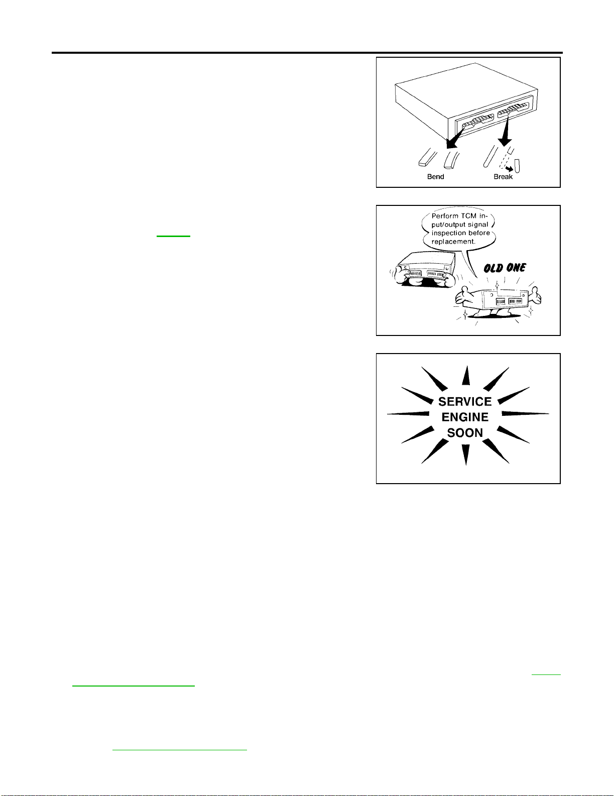
PRECAUTIONS
● When connecting or discon necting pin connectors into or
from TCM, take care not to damage pin term inals (bend or
break).
Make sure that th ere are not any bends or breaks on TCM
pin terminal, when connecting pin connectors.
● Before replacing TCM, perform TCM input/output signal
inspection and make s ure whether TCM fu nctions properly
or not. Se e page AT-107
.
[RE4F03B]
AAT470A
MEF040DA
● After performing each TROUBLE DIAGNOSIS, perform
“DTC (Diagnostic Trouble Code) CONFIRMATION PROCEDURE”.
The DTC should not be displa yed in the “DTC CONFIRMATION PROCEDURE” if the repair is completed.
● Before proceeding with disassembly, thoroughly clean th e out-
side of the transaxle. It is important to prevent the internal parts
from becoming contaminated by dirt or other foreign matter.
● Disassembly should be done in a clean work area.
● Use lint-free cloth or towels for wiping parts clean. Common
shop rags can leave fibers that could interfere with the operation
SAT964I
of the transaxle.
● Place disassembled parts in order for easier and proper assembly.
● All parts should be carefully cleaned with a general purpose, non-flammable solvent before inspection or
reassembly.
● Gaskets, seals and O-rings should be replaced any time the transaxle is disassembled.
● It is very important to perform functional tests whenever they are indicated.
● The valve bo dy co ntains precision parts and requires extreme ca re w h en parts are removed and s er v ic ed.
Place disassembled valve body parts in order for easier and proper assembly. Care will also prevent
springs and small part s from becoming scattered or lost.
● Properly installed valves, sle ev e s, plugs, etc. will slide alo ng bore s in va lv e bo dy unde r thei r own we ig ht.
● Before assembly, apply a coat of recommended ATF to all parts. Apply petroleum jelly to protect O-rings
and seals, or hold bearings and washers in place during assembly. Do not use grease.
● Extreme care should be taken to avoid damage to O-rings, seals and gaskets when assembling.
● Replace ATF cooler if excessive foreig n material is fo und in oil pan or cl ogging strai ner. Refer to AT-11,
"ATF COOLER SERVICE" .
● After over haul, refill the transaxle with new ATF.
● When the A/T drain plug is remove d, only some of t he fluid is drai ned. O ld A/T flu id wil l remain i n torque
converter and ATF cooling system.
Always follow the procedures unde r “Changing A/T Fluid” in the MA section when changing A/T fluid.
Refer to MA-31, "
Changing A/T Fluid" .
AT-10
Page 55

PRECAUTIONS
[RE4F03B]
Service Notice or Precautions ECS004CO
FAIL-SAFE
The TCM has an electronic Fail-Safe (limp home mode). Th is allows t he vehicl e to be dri ven even if a major
electrical input/output device circuit is damaged.
Under Fail-Safe, the vehicle always runs in third gear, even with a shift lever position of “1”, “2” or “D”. The customer may complain of sluggish or poor acceleration.
When the ignition key is turned “ON” following Fail-Safe operation, O/D OFF indicator lamp blinks for about 8
seconds. [For “TCM Self-diagnostic Procedure (No Tools)”, refer to AT- 50 , "
(No Tools)" .]
The blinking of the O/D OFF indicator lamp for about 8 seconds will appear only once and be cleared. The
customer may resume normal driving conditions.
Always follow the “Work Flow”. Refer to AT-60, "
Work Flow" .
The SELF-DIAGNOSIS results will be as follows:
● The first SELF -DIAGNOSIS will indicate damage to the vehi cle speed sensor or the revolution sensor.
● During the next SELF-DIAGNOSIS, performed after checking the sensor, no damages will be indicated.
TORQUE CONVERTER SERVICE
The torque converter should be replaced under any of the following conditions:
● External leaks in the hub weld area.
● Converter hub is scored or damaged.
● Converter pilot is broken, damaged or fits poorly into crankshaft.
● Steel particles are found aft er flushing the cooler and coo ler lines.
● Pump is damaged or steel particle s are foun d in the con ve rte r.
● Vehicle has TCC shudder and/or no TCC apply. Replace only after all hydraulic and electrical diagnoses
have been made. (Converter clutch material may be glazed.)
● Converter is contaminated with engine coolant containing antifreeze.
● Internal failure of stator roller cl utc h .
● Heavy clutch debris due to overheating (blue converter).
● Steel particles or clutch lining materi al foun d in f luid fi lter or on mag net wh en no interna l parts in unit are
worn or damaged — indicates that lining material came from converter.
The torque converter should not be replaced if:
● The fluid has an odor, is discolored, and there is no evidence of metal or clutch facing particles.
● The threads in one or more of the converter bolt holes are damaged.
● Transaxle failure did not display evidence of damaged or worn internal parts, steel particles or clutch plate
lining material in unit and inside the fluid filter.
● Vehicle has been exposed to high mileage (only). The exception may be where the torque converter
clutch dampener plate lining has seen excess wear by vehicles operated in heavy and/or constant traffic,
such as taxi, delivery or police use.
ATF COOLER SERVICE
Replace ATF cooler if excessive foreign material is found in oil pan or clogging strainer.
Replace radiator lower tank (which includes ATF cooler) with a new one and flush cooler line using cleaning
solvent and com pressed air.
Refer to CO-14, "
RADIATOR" .
TCM Self-diagnostic Procedure
A
B
AT
D
E
F
G
H
I
J
K
L
M
OBD-II SELF-DIAGNOSIS
● A/T self-diagnosis is performed by the TCM in combination with the ECM. The results can be read through
the blinking pattern of the O/D OFF indicator or the malfunction indicator lamp (MIL). Refer to the table on
AT-54, "
● The self-dia gnostic results indicated by the MIL are automaticall y stored in the ECM and TCM memories.
Always perform the procedure “HOW TO ERASE DTC” on page AT-39
avoid unnecessary blinking of the MIL.
● The following self-diagnostic items can be detected using ECM self-diagnostic results mode* only when
the O/D OFF indicator lamp does not indicate any malfunctions.
– PNP switch
– A/T 1st, 2nd, 3rd, or 4th gear function
Judgement of Self-diagnosis Code" for the indicator used to display each self-diagnostic result.
to complete the repair and
AT-11
Page 56

PRECAUTIONS
[RE4F03B]
– A/T TCC S/V function (lock-up).
*: For details of OBD-II, refer to EC-60, "
CA Model)] or EC-625, "
● Certain systems and componen ts, especially those relate d to OBD, may use a new style slide-
ON BOARD DIAGNOSTIC (OBD) SYSTEM" [QG18DE (Calif. CA Model)].
locking type harness connector.
For description and how to disconnect, refer to PG-50, "
TYPE)" .
ON BOARD DIAGNOSTIC (OBD) SYSTEM" [QG18DE (Except Calif.
HARNESS CONNECTOR (SLIDE-LOCKING
Wiring Diagrams and Trouble Diagnosis ECS004CP
When you read wiring diagrams, refer to the following:
● GI-13, "How to Read Wiring Diagrams".
● PG-2, "POWER SUPPLY ROUTING".
When you perfo rm trouble diagnosis, refer to the following:
● GI-10, "HOW TO FOLLOW TEST GROUPS IN TROUBLE DIAGNOSES".
● GI-26, "How to Perform Efficient Diagnosis for an Electrical Incident".
AT-12
Page 57
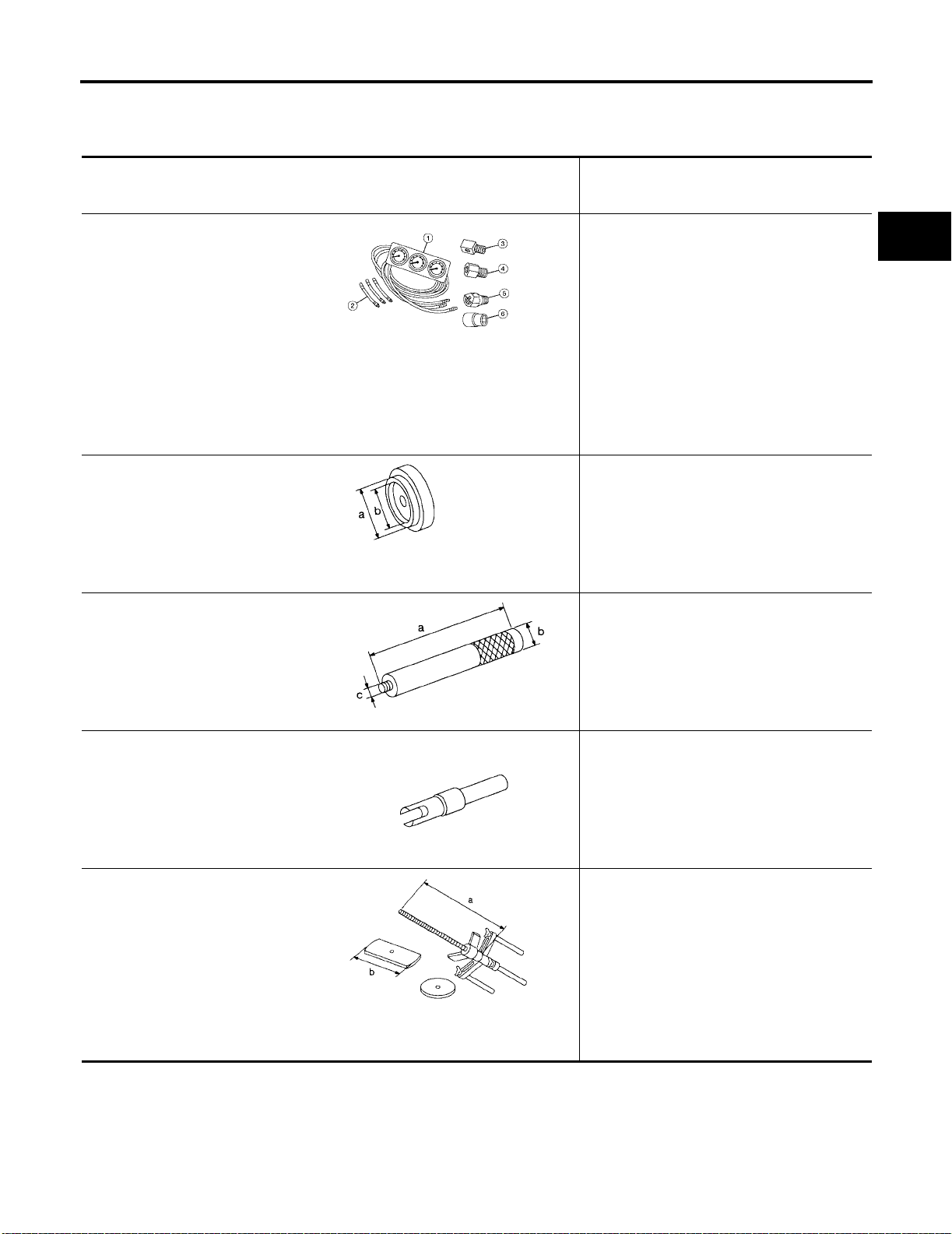
PREPARATION
[RE4F03B]
PREPARATION PFP:00002
Special Service Tools ECS 004CQ
The actual shapes of Kent-Moore tools may differ from those of spec ial ser vi ce tool s illust rat ed here.
Tool number
(Kent-Moore No.)
Tool name
(J34301-C)
Oil pressure gauge set
1 (J34301-1)
Oil pressure gauge
2 (J34301-2)
Hoses
3 (J34298)
Adapter
4 (J34282)
Adapter
5 (790-301-1230-A)
60° Adapter
6 (J34301-15)
Square socket
AAT896
Description
Measuring line pressure
A
B
AT
D
E
F
KV31103000
(J38982)
Drift
ST35325000
(—)
Drift
KV38107700
(J39027)
Preload adapter
KV31103200
(J34285-A and J34285-87)
Clutch spring compressor
NT105
NT417
NT087
Installing differential oil seal
(Use with ST35325000.)
a: 59 mm (2.32 in) dia.
b: 49 mm (1.93 in) dia.
Installing differential oil seal
(Use with KV31103000.)
a: 215 mm (8.46 in)
b: 25 mm (0.98 in) dia.
c: M12 x 1.5P
● Measuring turning torque of final drive as-
sembly
● Measuring clearance between side gear
and differential case with washer
● Selecting differential side bearing adjusting
shim
Removing and installing clutch return spring
a: 320 mm (12.60 in)
b: 174 mm (6.85 in)
G
H
I
J
K
L
M
NT423
AT-13
Page 58
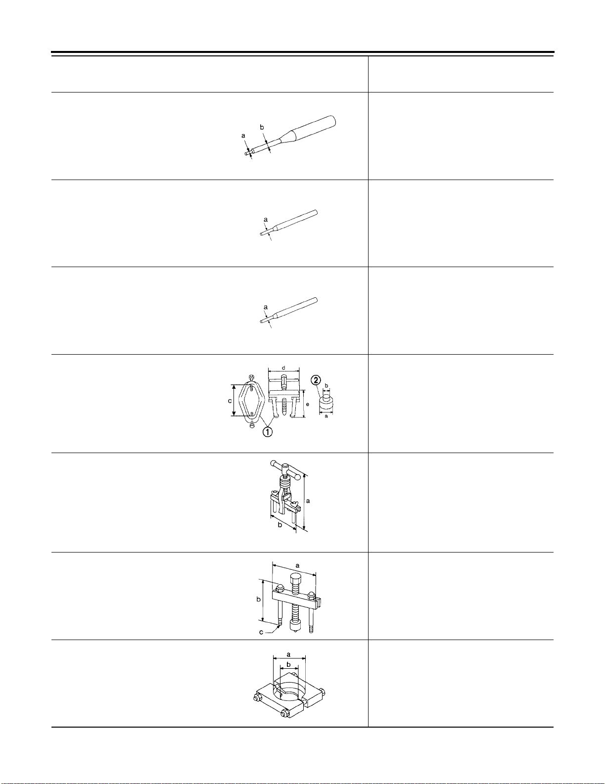
Tool number
(Kent-Moore No.)
Tool name
ST23540000
(J25689-A)
Pin punch
KV32101000
(J25689-A)
Pin punch
ST25710000
(—)
Pin punch
PREPARATION
[RE4F03B]
Description
Removing and installing parking rod pla te ,
manual plate and differential pinion mate shaft
retaining pins
a: 2.3 mm (0.091 in) dia.
b: 4 mm (0.16 in) dia.
NT442
Installing throttle lever and manual shaft retaining pins
a: 4 mm (0.16 in) dia.
NT410
Aligning groove of manual shaft and hole of
transmission case
a: 2 mm (0.08 in) dia.
ST3306S001
(J22888-D)
Differential side bearing puller set
1 ST33051001
(J22888-D)
Puller
2 ST33061000
(J8107-2)
Adapter
KV381054S0
(J34286)
Puller
ST27180001
(J25726-B)
Puller
ST30031000
(J22912-O1)
Puller
NT410
NT745
NT414
NT424
Removing differential side bearing in ner race
a: 39 mm (1.54 in) dia.
b: 29.5 mm (1.161 in) dia.
c: 130 mm (5.12 in)
d: 135 mm (5.31 in)
e: 120 mm (4.72 in)
● Removing idler gear bearing outer race
● Removing differential side oil seals
● Removing differential side bearing outer
race
● Removing needle bearing from bear in g re-
tainer
a: 250 mm (9.84 in)
b: 160 mm (6.30 in)
● Removing idler gear
a: 100 mm (3.94 in)
b: 110 mm (4.33 in)
c: M8 x 1.25P
Removing reduction gear bearing inner race
a: 90 mm (3.54 in) dia.
b: 50 mm (1.97 in) dia.
NT411
AT-14
Page 59
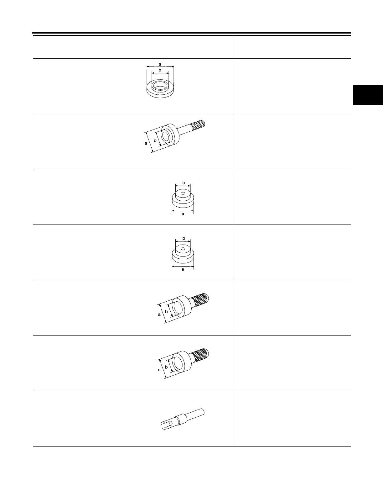
PREPARATION
[RE4F03B]
Tool number
(Kent-Moore No.)
Tool name
ST35272000
(J26092)
Drift
ST37830000
(—)
Drift
ST35321000
(—)
Drift
ST30633000
(—)
Drift
NT426
NT427
NT073
Description
● Installing reduction gear bearing inner race
● Installing idler gear bearing inner race
a: 72 mm (2.83 in) dia.
b: 35.5 mm (1.398 in) dia.
Installing idler gear bearing outer race
a: 62 mm (2.44 in) dia.
b: 39 mm (1.54 in) dia.
Installing output shaft bearing
a: 49 mm (1.93 in) dia.
b: 41 mm (1.61 in) dia.
Installing differential side bearing outer race
a: 67 mm (2.64 in) dia.
b: 49 mm (1.93 in) dia.
A
B
AT
D
E
F
G
H
I
ST35271000
(J26091)
Drift
ST33400001
(J26082)
Drift
KV38105710
(—)
NT073
NT115
NT115
NT087
● Installing idler gear
a: 72 mm (2.83 in) dia.
b: 63 mm (2.48 in) dia.
● Installing oil pump housing oil seal
a: 60 mm (2.36 in) dia.
b: 47 mm (1.85 in) dia.
● Measuring clearance between side gear
and differential case
J
K
L
M
AT-15
Page 60
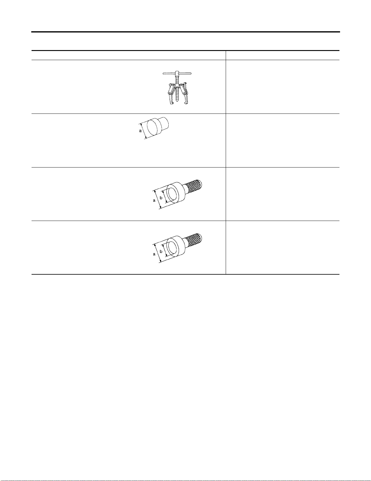
PREPARATION
[RE4F03B]
Commercial Service Tools ECS004CR
Tool name Description
Puller
NT077
Drift Removing idler gear bearing inner race
NT109
Drift Installing differential left side bearing
● Removing idler gear bearing inner rac e
● Removing and installing band serv o pisto n
snap ring
a: 34 mm (1.34 in) dia.
a: 86 mm (3.39 in) dia.
b: 80 mm (3.15 in) dia.
NT115
Drift Installing differential right side bearing
a: 46 mm (1.81 in) dia.
b: 40 mm (1.57 in) dia.
NT115
AT-16
Page 61
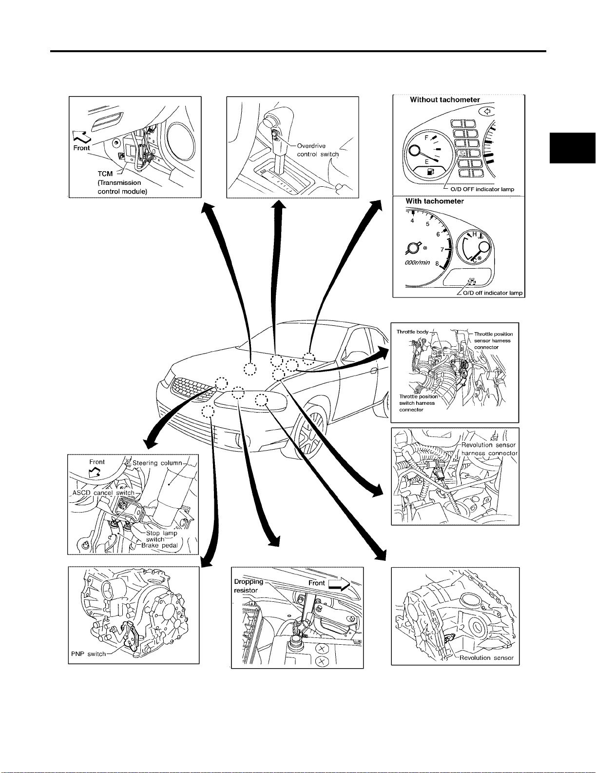
OVERALL SYSTEM
[RE4F03B]
OVERALL SYSTEM PFP:00000
A/T Electrical Parts Location ECS004CS
A
B
AT
D
E
F
G
H
M
I
J
K
L
WAT358
AT-17
Page 62
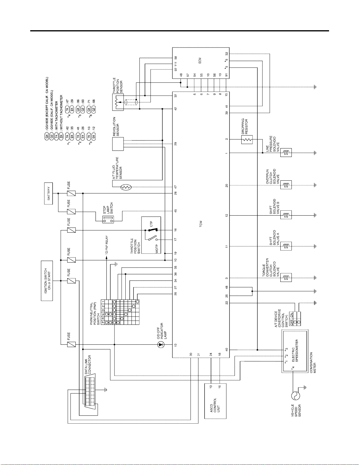
OVERALL SYSTEM
[RE4F03B]
Circuit Diagram ECS004CT
WDWA0001E
AT-18
Page 63
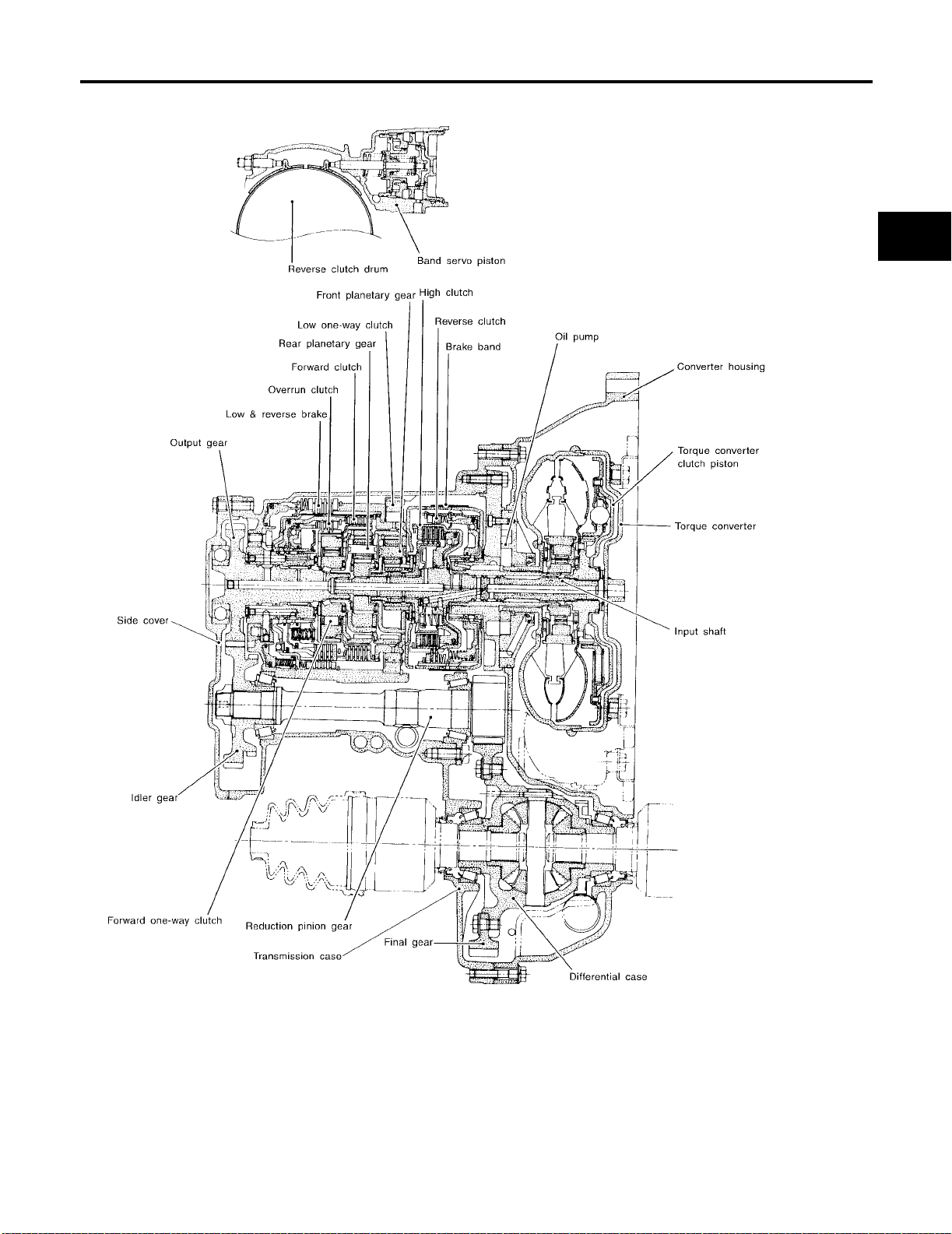
OVERALL SYSTEM
[RE4F03B]
Cross-sectional View ECS004CU
A
B
AT
D
E
F
G
H
M
I
J
K
L
SAT842J
AT-19
Page 64
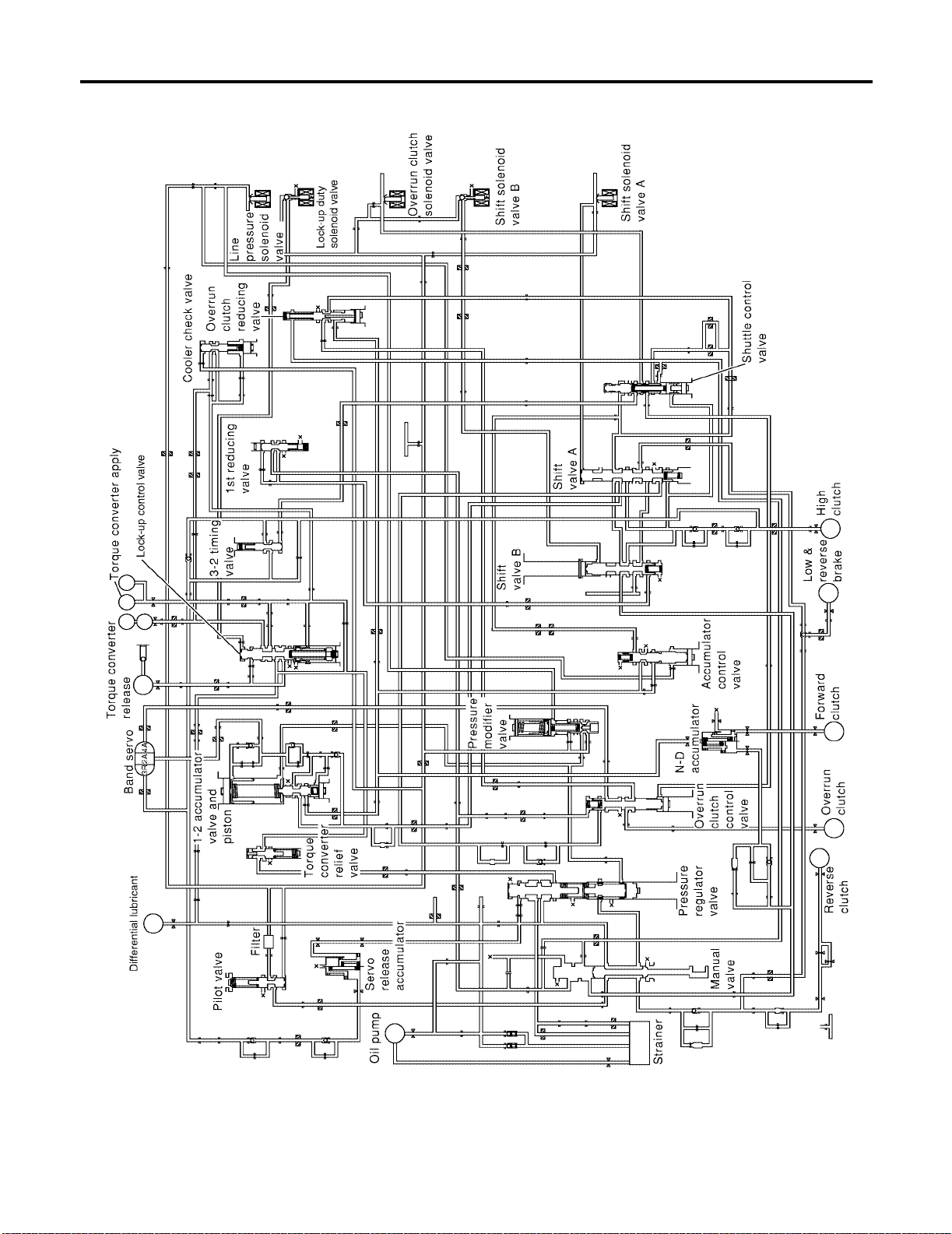
OVERALL SYSTEM
[RE4F03B]
Hydraulic Control Circuit E C S 004CV
WAT408
AT-20
Page 65
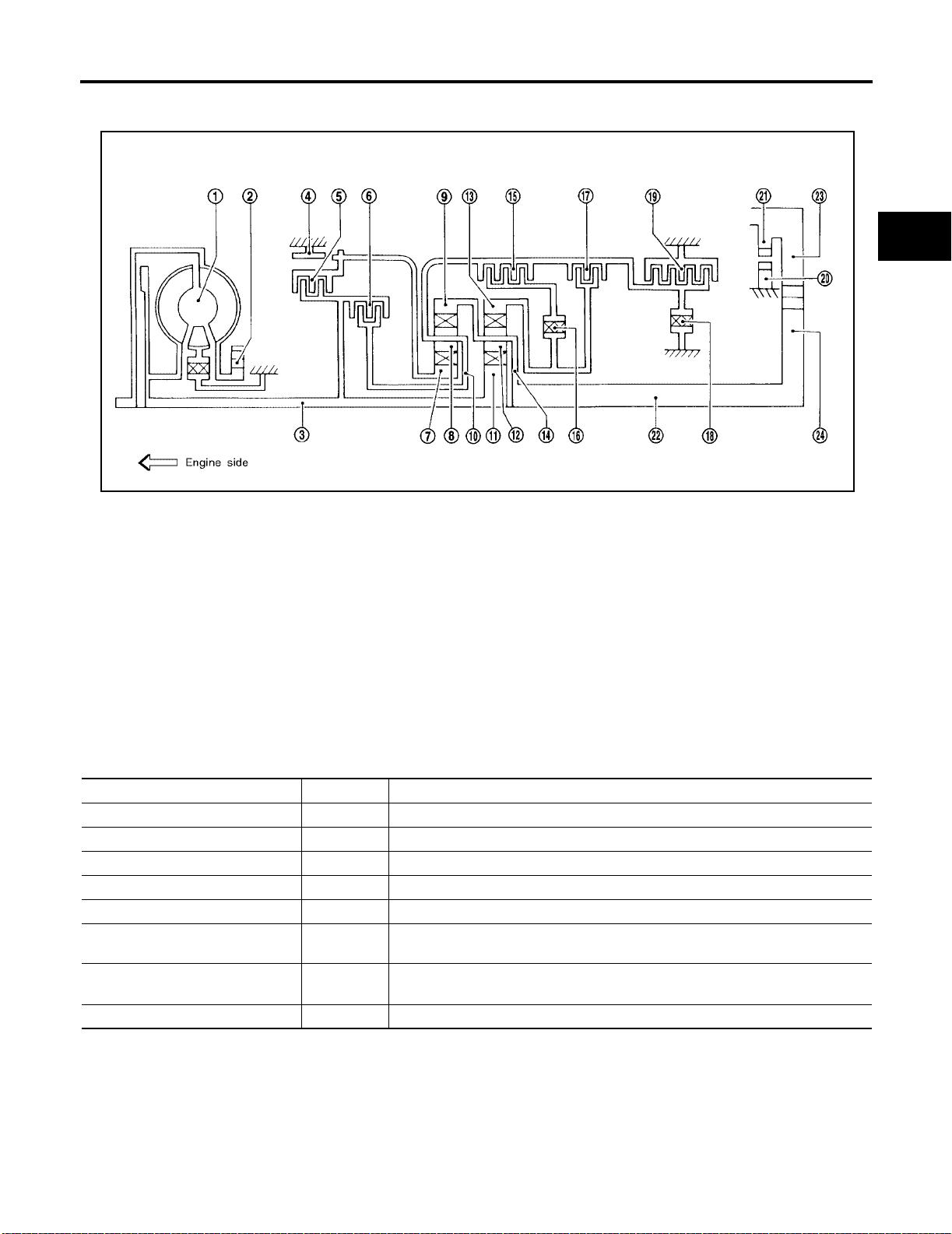
OVERALL SYSTEM
[RE4F03B]
Shift Mechanism ECS004CW
CONSTRUCTION
A
B
AT
D
E
F
SAT998I
1. Torque converter 2. Oil pump 3. Input shaft
4. Brake band 5. Reverse clutch 6. High clutch
7. Front sun gear 8. Front pinion gear 9. Front internal gear
10.Front planetary carrier 11.Rear sun gear 12.Rear pinion gear
13.Rear internal gear 14.Rear planetary carrier 15.Forward clutch
16.Forward one-way clutch 17.Overrun clutch 18.Low one-way clutch
19.Low & reverse brake 20.Parking pawl 21.Parking gear
22.Output shaft 23.Idle gear 24.Output gear
FUNCTION OF CLUTCH AND BRAKE
Clutch and brake components Abbr. Function
5 Reverse clutch R/C To transmit input power to front sun gear 7 .
6 High clutch H/C To transmit input power to front planetary carrier 10 .
15 Forward clutch F/C To connect front planetary carrier 10 with forward one-way clutch 16 .
17 Overrun clutch O/C T o connect front planetary carrier 10 with rear internal gear 13 .
4 Brake band B/B To lock front sun gear 7 .
16 Forward one-way clutch F/O.C When forward clutch 15 is engaged, to stop rear internal gear 13 from rotating in
opposite direction against engine revolution.
18 Low one-way clutch L/O.C To stop front planetary carrier 10 from rotating in opposite direction against
engine revolution.
19 Low & reverse brake L & R/B To lo ck front pla netary carri er 10 .
G
H
I
J
K
L
M
AT-21
Page 66
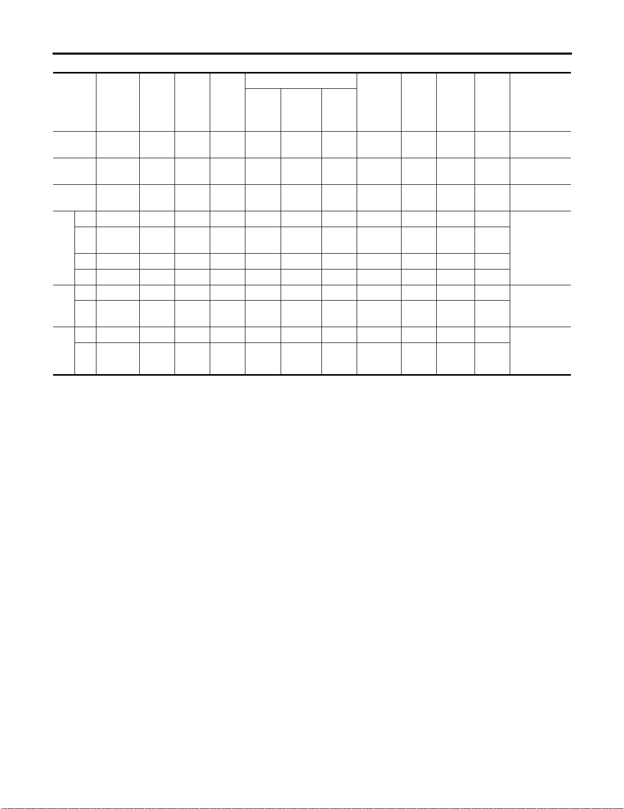
OVERALL SYSTEM
[RE4F03B]
CLUTCH AND BAND CHART
Shift
position
Reverse
clutch
5
High
clutch
6
For-
ward
clutch
15
Over-
run
clutch
17
2nd
apply
Band servo
3rd
release
4th
apply
Forward
one-way
clutch
16
P
RO O
N
1st O *1D B B
2n
D*
d
4
3rd O O *1A *2C C B *5O
O*1AO B
4th O C *3C C O O
1st O D B B
2
2n
d
OAO B
1st O O B O Locks (held
1
2n
d
● *1: Operates when overdrive control switch is set in “OFF ” posit io n.
● *2: Oil pressure is applied to both 2nd “apply” side and 3rd “release ” side of band ser vo piston. Howeve r, brake band does not con-
OOO B
tract because oil pressure area on the “release” side is greater than that on the “apply” side.
● *3: Oil pressure is applied to 4th “apply” side in cond ition *2 above, and brake band contracts.
● *4: A/T will not shift to 4th when overdrive control switch is set in “OFF” position.
● *5: Operates when overdrive control switch is “OFF” .
● O : Operates.
● A: Operates when throttle opening is less than 3/16, activating engine brake.
● B: Operates during “progressive” acceleration.
● C: Operates but does not affect power transmission.
● D: Operates when throttle opening is less than 3/16, but does not affect engine br ake.
Low
one-
way
clutch
18
Low &
reverse
brake
19
Lock-
up
Remarks
PARK
POSITION
REVERSE
POSITION
NEUTRAL
POSITION
Automatic
shift
1 ⇔ 2 ⇔ 3 ⇔
4
Automatic
shift
1 ⇔ 2
stationary) in
1st speed
1 ⇐ 2
AT-22
Page 67
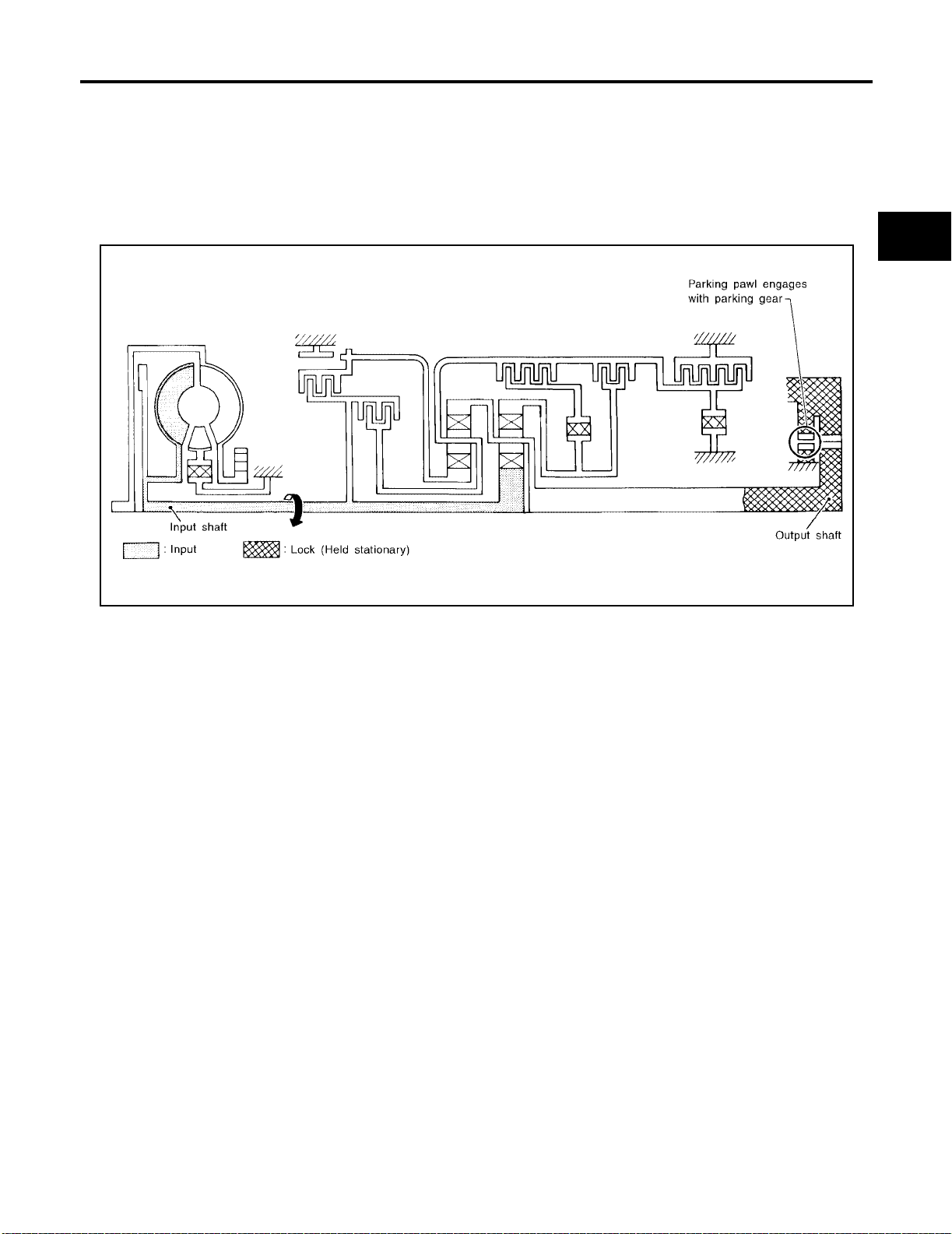
OVERALL SYSTEM
[RE4F03B]
POWER TRANSMISSION
“N” and “P” Positions
● “N” position
Power from the input shaft is not transmit ted to the outp ut shaft beca use the clutches do not operate.
● “P” position
Similar to the “N” position, the clutches do not operate. The parking pawl engages with the parking gear to
mechanically hold the output shaft so that the powertrain is locked.
A
B
AT
D
E
F
G
SAT991I
H
I
J
K
L
M
AT-23
Page 68
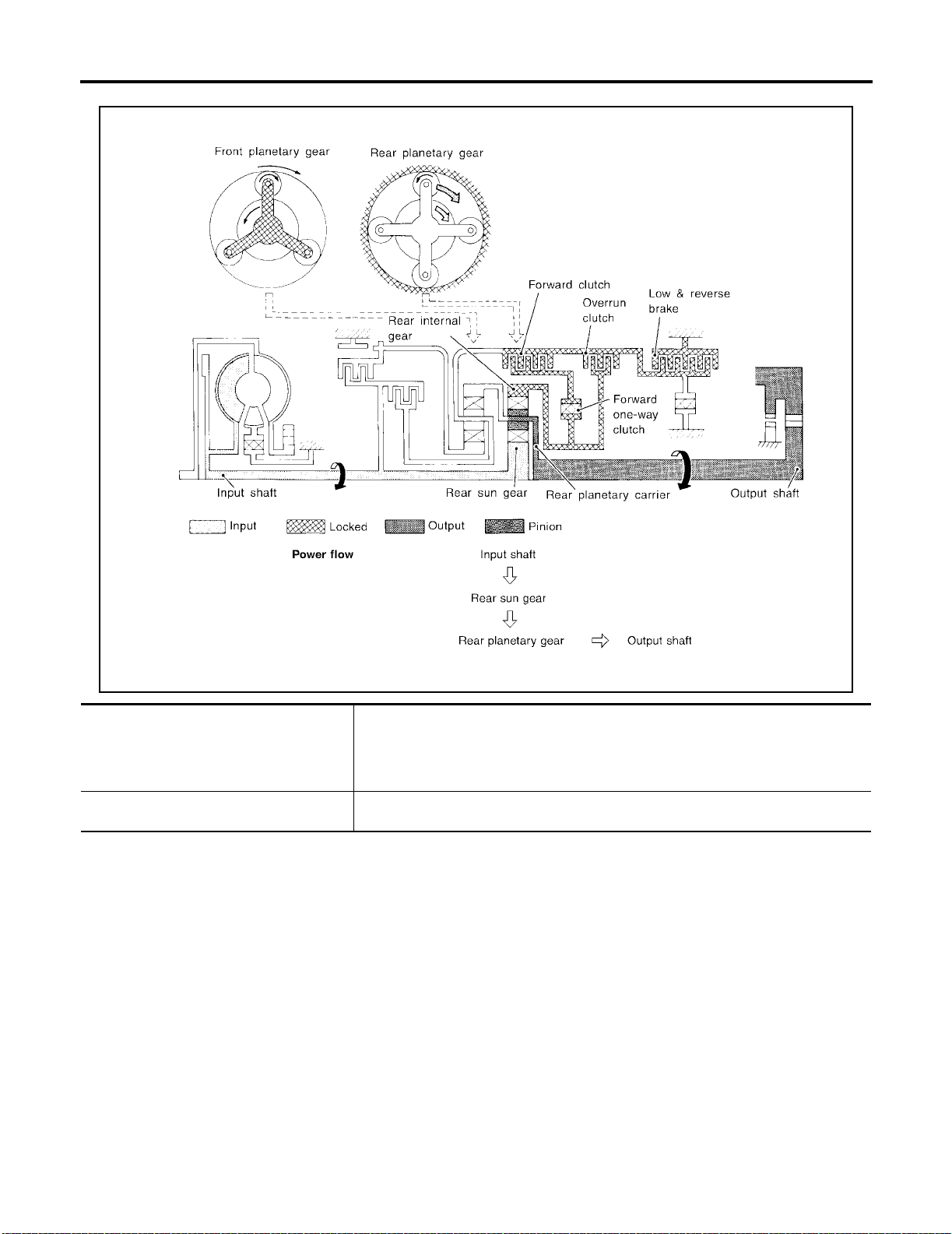
“11 ” Posit ion
OVERALL SYSTEM
[RE4F03B]
SAT374J
● Forward clutch
● Forward one-way clutch
● Overrun clutch
● Low and reverse brake
Engine brake Overrun clutch always engages, therefore engine brake can be obtained when deceler-
As overrun clutch engages, rear internal gea r is locked by t he oper at io n of low and
reverse brake.
This is diffe re n t from tha t o f D
ating.
1 and 21 .
AT-24
Page 69
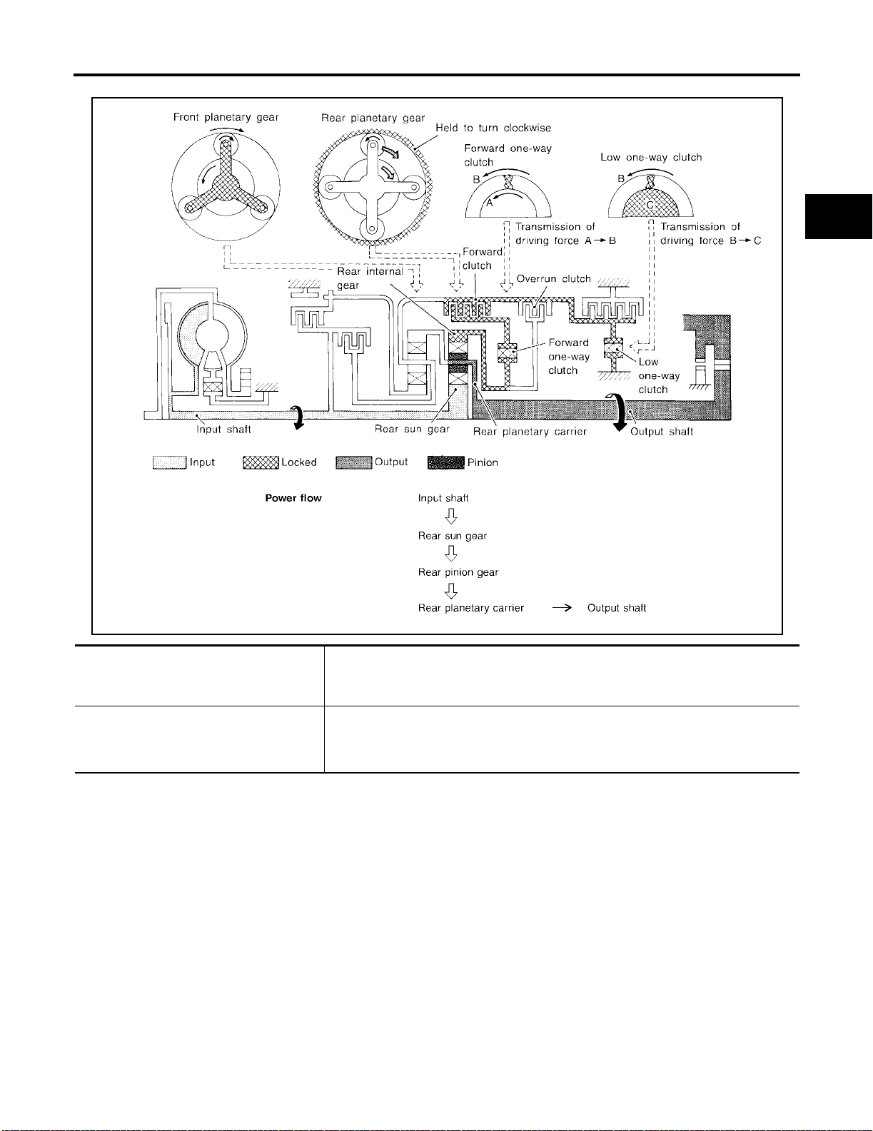
“D1 ” and “21 ” Positions
OVERALL SYSTEM
[RE4F03B]
A
B
AT
D
E
F
G
● Forward one-way clutch
● Forward clutch
● Low one-way clutch
Overrun clutch
engagement conditions
(Engine brake)
SAT377J
Rear internal gear is locked to rotate counterclock wise because of the functioning of
these three clutches.
D
1 : Overdrive control switch “OFF” and throttl e opening is less than 3/16
2
1 : Always engaged
1 and 21 positions, engine bra ke is not ac tivat ed du e to free t urn in g of low one-
At D
way clutc h.
H
I
J
K
L
M
AT-25
Page 70
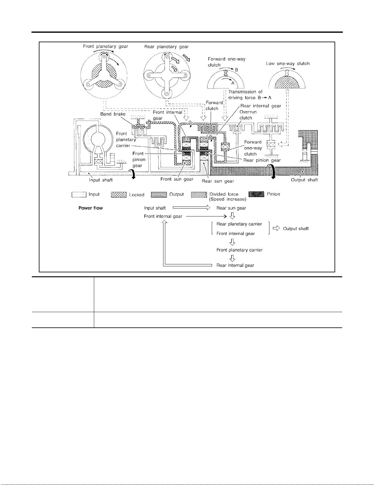
“D2 ”, “22 ” and “12 ” Positio n s
OVERALL SYSTEM
[RE4F03B]
● Forward clutch
● Forward one-way
clutch
● Brake band
Overrun clutch
engagement conditions
SAT378J
Rear sun gear drives rear planetary carrier and combined front internal gear. Front internal gear now
rotates around front sun gear accompanying front pl anetary car rier.
As front planetary carrier transfers the power to rear int ern al gear th rou gh fo rwar d cl utch and f orward oneway clutch, this rotation of rear internal gear increase s th e speed of rear planetary carrier compared with
that of the 1st speed.
2 : Overdrive control switch “OFF” and throttle opening is less than 3/16
D
2 and 12 : Always engaged
2
AT-26
Page 71
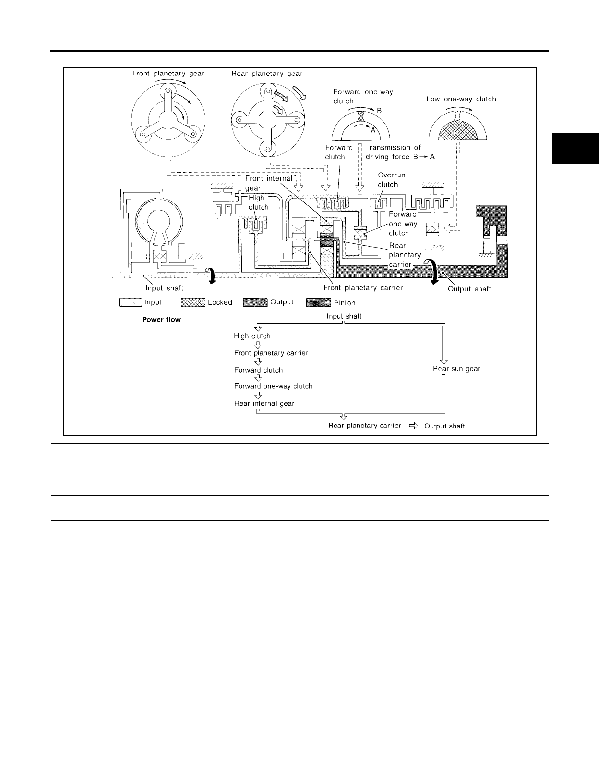
“D3 ” Position
OVERALL SYSTEM
[RE4F03B]
A
B
AT
D
E
F
G
● High clutch
● Forward clutch
● Forward one-way
clutch
Overrun clutch
engagement conditions
SAT379J
Input power is transmitted to front planetary carrier through high clutch. And front planetary carrier is connected to rear internal gear by operation of forward clutch and forward one-way clutch.
This rear internal gear rotation and another input (the rear sun gear ) acc om pany rear plan etary carrie r to
turn at the same speed.
D
3 : Overdrive control switch “OFF” and throttle opening is less tha n 3/1 6
H
I
J
K
L
M
AT-27
Page 72
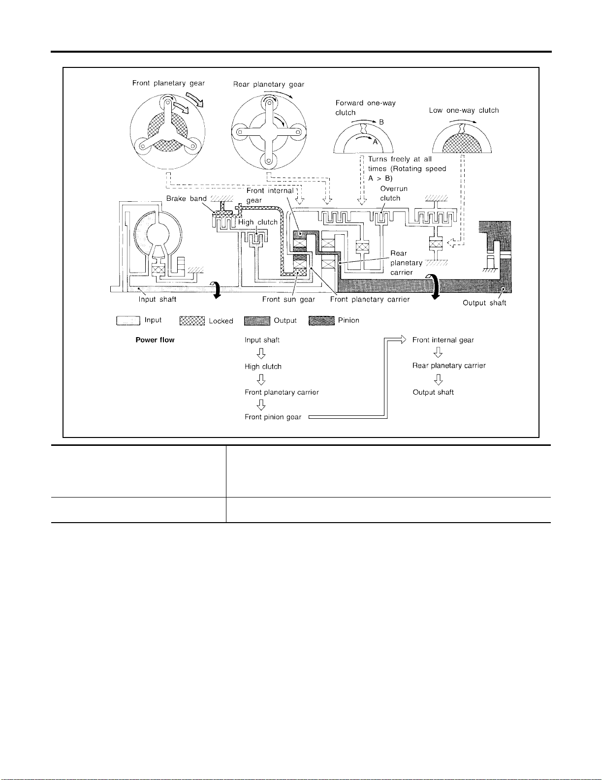
“D4 ” (OD) Position
OVERALL SYSTEM
[RE4F03B]
● High clutch
● Brake band
● Forward clutch (Does not affect power
transmission)
Engine brake
SAT380J
Input power is transmitted to front carrier through high clutch.
This front carrier turns around the sun gear which is fixed by brake band and makes
front internal gear (output) turn faster.
At D4 position, there is no one-way clutch in the power transmission line and engine
brake can be obtained when decelerating.
AT-28
Page 73
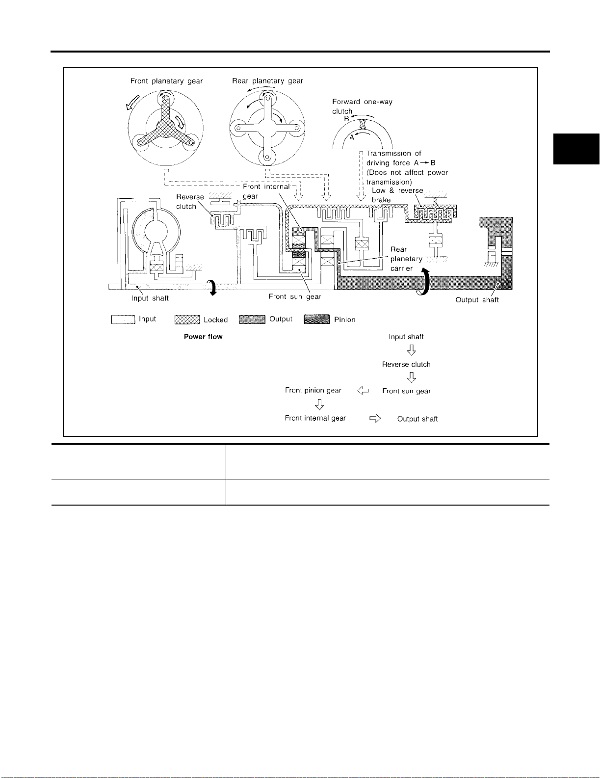
“R” Position
OVERALL SYSTEM
[RE4F03B]
A
B
AT
D
E
F
G
● Reverse clutch
● Low and reverse brake
Engine brake
SAT381J
Front planetary carrier is stationary because of the operation of low and reverse brake.
Input power is transmitted to front sun gear through reverse clutch, which drives front
internal gear in the opposite direction.
As there is no one-way clutch in the power transmission line, engine brake can be
obtained when decelerating.
H
I
J
K
L
M
AT-29
Page 74
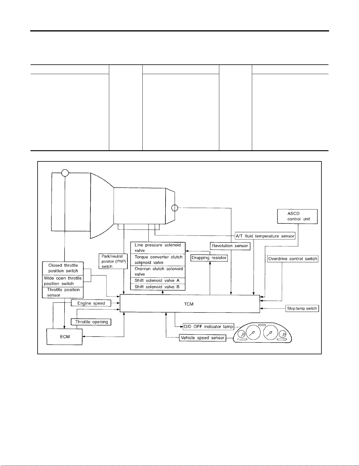
OVERALL SYSTEM
[RE4F03B]
Control System ECS004CX
OUTLINE
The automatic transaxle senses vehicle operating conditions through various switches and sensors. It always
controls the optimum shift position and reduces shifting and lock-up shocks.
SWITCHES & SENSORS TCM ACTUATORS
PNP switch
Throttle position sensor
Closed throttle position switch
Wide open throttle position
switch
Engine speed signal
A/T fluid temperature sensor
Revolution sensor
Vehicle speed sensor
Overdrive control switch
ASCD control unit
Stop lamp swit ch
CONTROL SYSTEM
Shift control
Line pressure control
Lock-up control
Overrun clutch control
Timing control
Fail-safe control
Self-diagnosis
CONSULT -II communication line
control
Duet-EA control
Shift solenoid valve A
Shift solenoid valve B
Overrun clutch solenoid valve
T orque converter clutch solenoid
valve
Line pressure solenoid valve
O/D OFF indicator lamp
WAT359
AT-30
Page 75
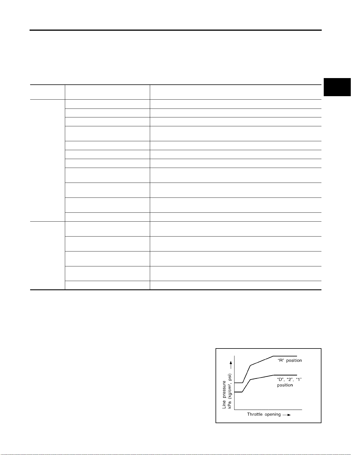
OVERALL SYSTEM
[RE4F03B]
TCM FUNCTION
The function of the TCM is to:
● Receive input signals sent from various switches and sensors.
● Determine required line pressure, shifting point, lock-up operation, and engine brake operation.
● Send required output signals to the respective solenoids.
INPUT/OUTPUT SIGNAL OF TCM
Input
Output
Sensors, switches and solenoid
valves
PNP switch Detects select lever position and sends a signal to TCM.
Throttle position sensor Detects throttle valve position and sends a signal to TCM.
Closed throttle position switch Detects throttle valve's fully-closed position and sends a signal to TCM.
Wide open throttle position switch
Engine speed signal From ECM.
A/T fluid temperature sensor Detects transmission fluid temperature and sends a signal to TCM.
Revolution sensor Detects outpu t sha ft rpm and sends a signal to TCM.
Vehicle speed sensor
Overdrive control switch
ASCD control unit
Stop lamp switch Releases lock-up system when depressing pedal in lock-up condition.
Shift solenoid valve A/B
Line pressure solenoid valve
Torq ue converter clutch solenoid
valve
Overrun clutch solenoid valve
O/D OFF indicator lamp Shows TCM faults, when A/T control components malfunction.
Detects a throttle valve position of greater than 1/2 of full throttle and sends a
signal to TCM.
Used as an auxiliary vehicle speed sensor. Sends a signal when revolution
sensor (installed on transmission) malfunctions.
Sends a signal, which prohibits a shift to “D
TCM.
Sends the cruise signal and “D
control unit to TCM.
Selects shifting point suited to driving conditions in relati on to a signa l sent
from TCM.
Regulates (or decreases) line pressure suited to driving conditions in relation
to a signal sent from TCM.
Regulates (or decreases) lock-up pr essure suited to driving conditions in relation to a signal sent from TCM.
Controls an “engine brake” effect suited to driving condi tions in relati on t o a
signal sent from TCM.
Function
4 ” (overdrive) p o si tion, to the
4 ” (overdrive) cancellation signal from ASCD
Control Mechanism ECS004CY
LINE PRESSURE CONTROL
TCM has various line pressure control characteristics to match the driving conditions.
An ON-OFF duty signal is sent to the line pressure solenoid valve based on TCM characteristics.
Hydraulic pr essu r e o n the cl ut ch and br a ke is e le ct ron ic al l y c on tro ll ed thr o ugh th e li ne pr ess ure so le no i d v alve
to accommodate engine torque. This results in smooth shift operation.
A
B
AT
D
E
F
G
H
I
J
K
L
M
Normal Control
The line pressure to throttle opening characteristics is set for suitable
clutch operation.
AT-31
SAT003J
Page 76
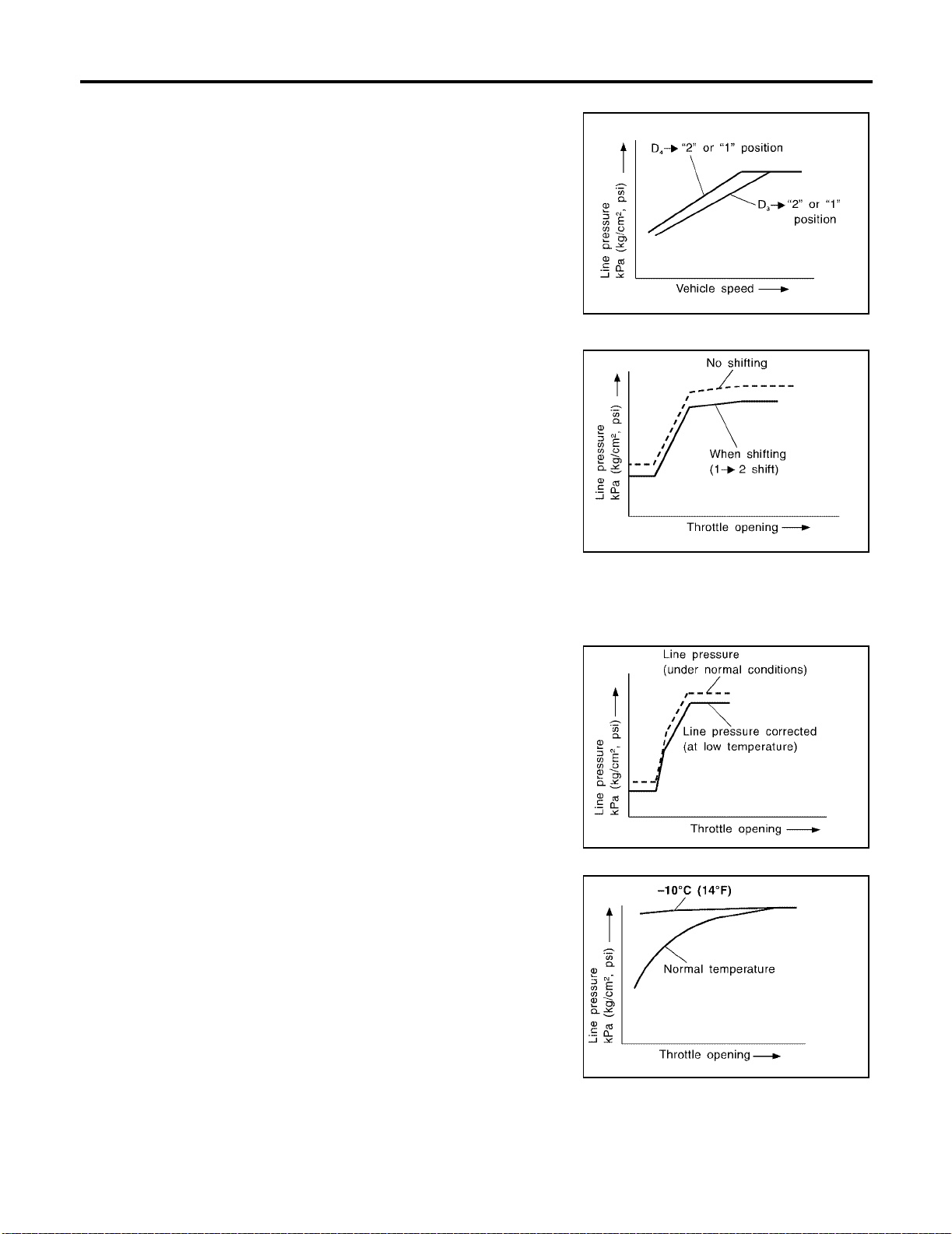
OVERALL SYSTEM
Back-up Control (Engine brake)
If the selector lever is shifted to “2” position while driving in D4 (OD)
or D
3 , great driving force is applied to the clutch inside the transmis-
sion. Clutch operating pressure (line pressure) must be increased to
deal with this driving force.
During Shift Change
The line pressure is temporari ly reduce d correspon ding to a c hange
in engine torqu e w h en s hi ftin g ge ars (t ha t is , w he n t he s hif t s ol en oi d
valve is switched for clutch operation) to reduce shifting shock.
[RE4F03B]
SAT004J
SAT005J
At Low Fluid Temperature
● Fluid viscosity and frictional characteristics of the clutch facing change with fluid temperature. Clutch
engaging or band-contacting pressure is compensated for, according to fluid temperature, to stabilize
shifting quality.
● The line pressure is reduced below 60°C (140°F) to prevent
shifting shock due to low viscosity of automatic transmission
fluid when temperature is low.
SAT006J
● Line pressure is increased to a maximum, irrespective of the
throttle opening, when fluid temperature drops to −10°C (14°F).
This pressure rise is adopted to prevent a delay in clutch and
brake operation due to extreme drop of fluid viscosity at low
temperature.
SAT007J
SHIFT CONTROL
The shift is regulated entirely by electronic control to accommodate vehicle speed and varying engine operations. This is accomplished by electrical signals transmitted by the revolution sensor and throttle position sensor . This results in improved acceleration performance and fuel economy.
AT-32
Page 77
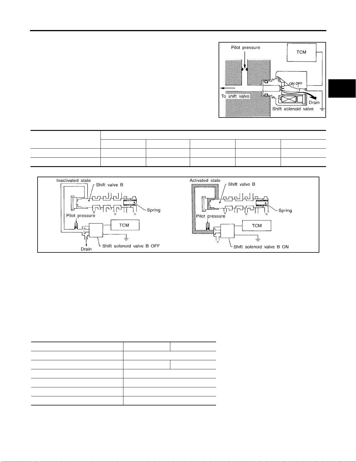
OVERALL SYSTEM
Control of Shift Solenoid Valves A and B
The TCM activa tes shift solenoid valv es A and B according t o signals from the throttle position sensor and revolution sensor to select
the optimum gear p osition on the basis of the shift sc hedule me morized in the TCM.
The shift sole noid valve perfor ms simple ON-OFF op eration. When
set to “ON”, the drain c ircuit closes and pilot pres sure is applied to
the shift valve.
[RE4F03B]
A
B
AT
SAT008J
Relation Between Shift Solenoid Valves A and B and Gear Positions
Shift solenoid valve
A ON (Closed) OFF (Open) OFF (Open) ON (Closed) ON (Closed)
B ON (Closed) ON (Closed) OFF (Open) OFF (Open) ON (Closed)
1 , 21 , 11 D2 , 22 , 12 D3 D4 (OD) N-P
D
Gear position
Control of Shift Valves A and B
SAT009J
Pilot pressure g enerated by the opera tion of shi ft solenoid valves A a nd B is ap plied to t he end face of shift
valves A and B.
The drawing above shows the operation of shift valve B. When the shift solenoid valve is “ON”, pilot pressure
applied to the end face of the shift valve overcomes spring force, moving the valve upward.
D
E
F
G
H
I
J
K
LOCK-UP CONTROL
The torque converter clutch piston in the torque converter is locked to eliminate torque converter slip to
increase power transmission efficiency. The solenoid valve is controlled by an ON-OFF duty signal sent from
the TCM. The signal is converted to an oil pressure signal which controls the torque converter clutch piston.
Conditions for Lock-up Opera tion
When vehicle is driven in 4th gear position, vehicle speed and throttle opening are detected. If the detected
values fall w ithin the loc k -up zone memorized in the TCM, lock-up is performed.
Overdrive control switch ON OFF
Selector lever “D” position
Gear position D
Vehicle speed sensor More than set value
Throttle position sensor Less than set opening
Closed throttle position switch OFF
A/T fluid temperature sensor More than 40°C (104°F)
4 D3
AT-33
L
M
Page 78
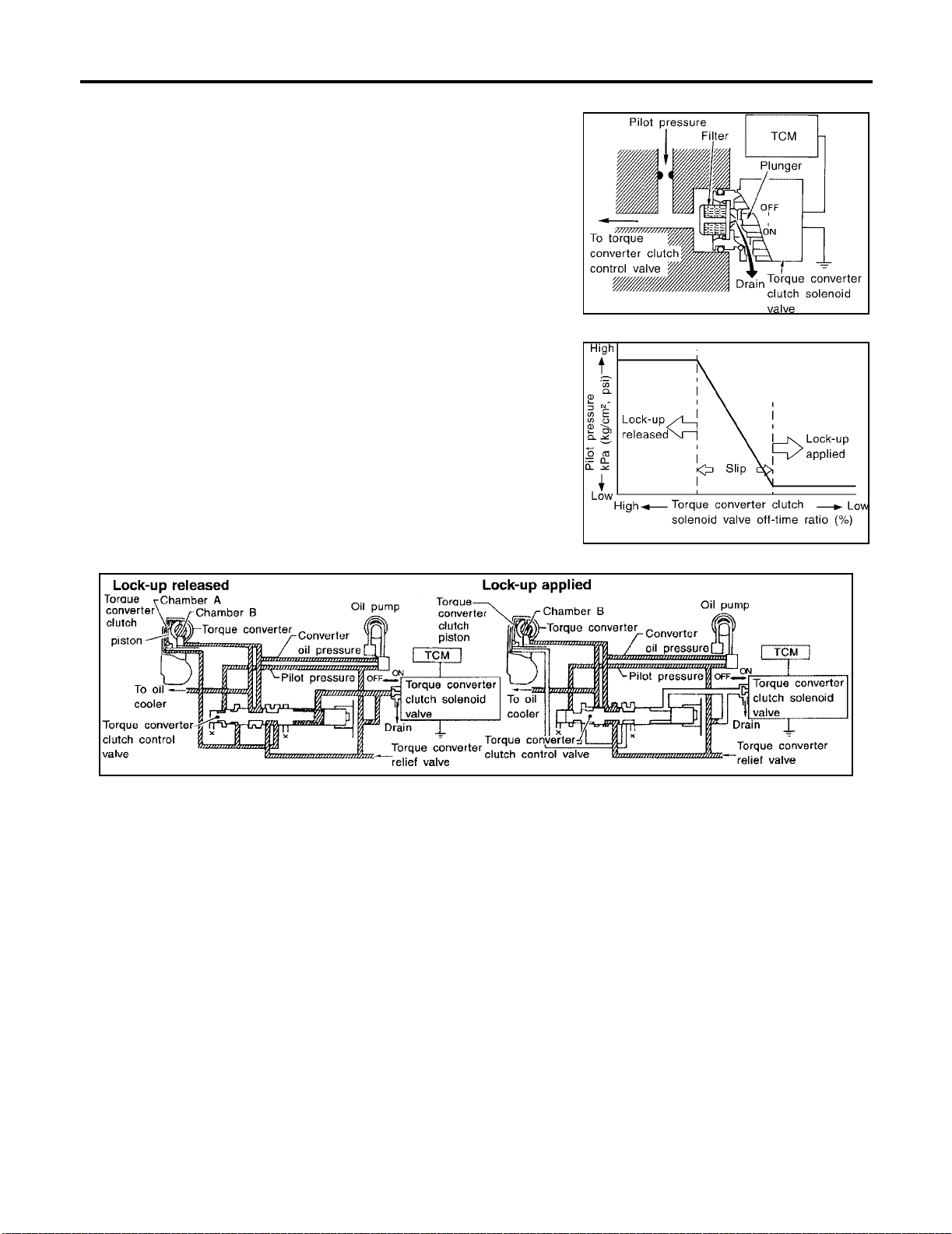
OVERALL SYSTEM
Torque Converter Clutch Solenoid Valve Control
The torque converter clutch solenoid valve is controlled by the TCM.
The plunger closes the drain circuit during the “OFF” period, and
opens the circuit during the “ON” period. If the percentage of OF Ftime increases in one cycle, the pilot pressure drain time is reduced
and pilot pressure remains high.
The torque conv erter clutch piston is de signed to slip to adju st the
ratio of ON-OFF, thereby reducing lock-up shock.
OFF-time INCREASING
↓
Amount of drain DECREASING
↓
Pilot pressure HIGH
↓
Lock-up RELEASING
[RE4F03B]
SAT010J
SAT011J
Torque Converter Clutch Control Valve Operation
AAT155A
Lock-up released
The OFF-duration of the torque conv erter clutch sole noid valve is long , and pilot pressu re is high. The pil ot
pressure pushes the end face of the torque c onverter cl utch control va lve in com bination wit h spring forc e to
move the valve to the left. As a result, converter pressure is applied to chamber A (torque converter clutch piston release side). Accordingly, the torque converter clutch piston remains unlocked.
Lock-up applied
When the OFF-duration of the torque converter clutch solenoid valve is short, pilot pressure drains and
becomes low. Accordingly, the control valve moves to the right by the pilot pressure of the other circuit and
converter pressu re. As a result, converter pressure is applied to chamber B, keeping t he torque converter
clutch piston applied.
Also smooth lock-up is provided by transient application and release of the lock-up.
OVERRUN CLUTCH CONTROL (ENGINE BRAKE CONTROL)
Forward one-way clutch is used to reduce shifting shocks in downshifting operations. This clutch transmits
engine torque to the wheels. However, drive force from the wheels is not transmitted to the engine because
the one-way clutch rotates idle. This means the engine brake is not effective.
The overrun clutch operates when the engine brake is needed.
AT-34
Page 79
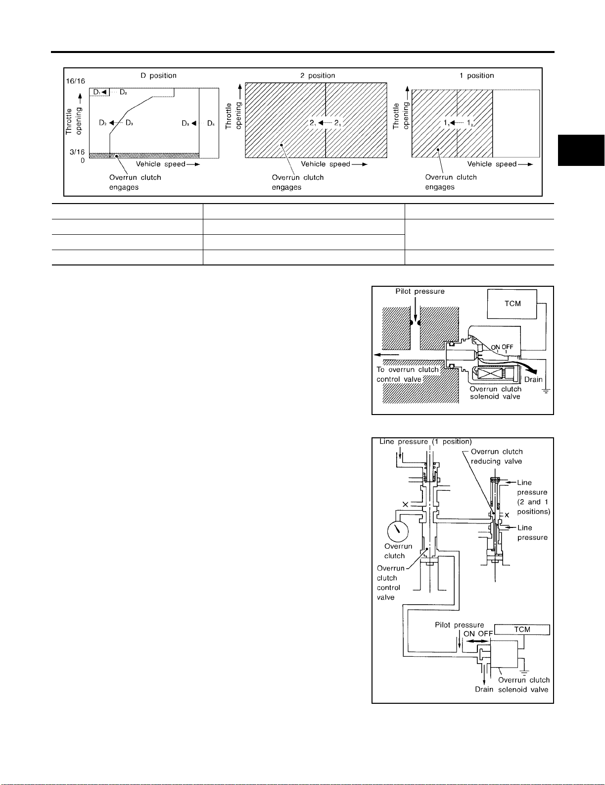
OVERALL SYSTEM
Overrun Clutch Operating Conditions
[RE4F03B]
A
B
AT
Selector lever position Gear position Throttle opening
“D” position D
“2” positio n 2
“1” positio n 1
1 , D2 , D3 gear position
1 , 22 gear position
1 , 12 gear position At any position
Overrun Clu t c h Solenoid Valve Control
The overrun cl utch s olenoid valve i s opera ted by an ON-O FF sign al
transmitted by the TCM to provide overrun clutch control (engine
brake control).
When this solenoid valve is “ON”, the pilot pressure drain port
closes. When it is “OFF”, the drain port opens.
During the sole noid valve “ON”, pilot pressure i s applied to th e end
face of the overrun clutch control valve.
Overrun Clutch Control Valve Operation
When the solenoid valve is “ON”, pilot pressure is applied to the
overrun clutch control valve. This pushes up the overrun clutch control valve. The line pressure is th en shut off so that the clutch does
not engage.
When the solenoid valve is “OFF”, pilot pressure is not generated. At
this point, the overrun clutch control valve moves downward by
spring force. As a result, ov errun clutch operation pressure is provided by the overrun clutch reducing valve. This causes the overrun
clutch to engage.
In the 1 position, the overrun clut ch control valve remains pushed
down so that the overrun clutch is engaged at all times.
Less than 3/16
SAT014J
SAT015J
D
E
F
G
H
I
J
K
L
M
SAT016J
Control Valve ECS004CZ
FUNCTION OF CONTROL VALVES
AT-35
Page 80

OVERALL SYSTEM
[RE4F03B]
Valve name Function
Pressure regulator valve, plug
and sleeve
Pressure modifier valve and
sleeve
Pilot valve Regulates line pressure to maintain a constant pilot pressure level which controls lock-up mecha-
Accumulator control valve Regulates accumulator back-pre ssur e to press ure sui ted to driving conditions.
Manual valve Directs line pressure to oil circuits corresponding to select positions.
Shift valve A Simultaneously switches four oil circuits using output pressure of shift solenoid valve A to meet
Shift valve B Simultaneously switches three oil circuits using output pressure of shift solenoid valve B in rela-
Overrun clutch control valve Switches hydraulic circuits to prevent engagement of the overrun clutch simultaneously with appli-
1st reducing valve Reduces low & reverse brake pressure to dampen engine-brake shock when down-shift in g from
Overrun clutch reducing valve Reduces oil pressure directed to the overrun clutch and prevents engine-brake sho ck.
Torq ue converter relief valve Prev ents an exc ess ive rise in torque converter pressure.
Torq ue converter clutch control
valve, plug and sleeve
1-2 accumulator valve and piston Dampens the shock encountered when 2nd gear band ser vo contracts, and provides smooth
3-2 timing valve Switches oil pressure with 3-2 tim in g val ve acc ord in g to thro ttle openi ng.
Shuttle control valve Reduces shock when down-shiftin g from 3rd to 2nd and regulates overrun clutch.
Cooler check valve Regulates oil pressure which causes lock-up when driving at low speeds.
Regulates oil discharged from the oil pump to prov ide optim um line pr essure for all driving conditions.
Used as a signal supplementary valve to the pressure regulator valve. Regulates pressure-modifier pressure (signal pressure) which contro ls optim um line pr ess ure f or all driving conditions.
nism, overrun clutch, shift timing.
Hydraulic pressure drains when the shift lever is in Neutral.
driving conditions (vehicle speed, throttle opening, etc.).
Provides automatic downshifting and up-shifting (1st → 2nd → 3rd → 4th gears/4th → 3rd → 2nd
→ 1st gears) in combination with shift valve B .
tion to driving conditions (vehicle speed, throttle opening, etc.).
Provides automatic downshifting and up-shifting (1st → 2nd → 3rd → 4th gears/4th → 3rd → 2nd
→ 1st gears) in combination with shift valve A .
cation of the brake band in D
the “1” position 1
In “1” and “2” positions, line pressure acts on the overrun clutch reduc in g valve to inc rea se th e
pressure-regulating point, with resultant engine brake capability.
Activates or inactivates the lock-up functio n.
Also provides smooth lock-up through tran sie nt applic ation and release of the lock-up system.
shifting.
2 to 11 .
4 . (Interlocking occurs if the overrun clutch engages during D4 .)
AT-36
Page 81
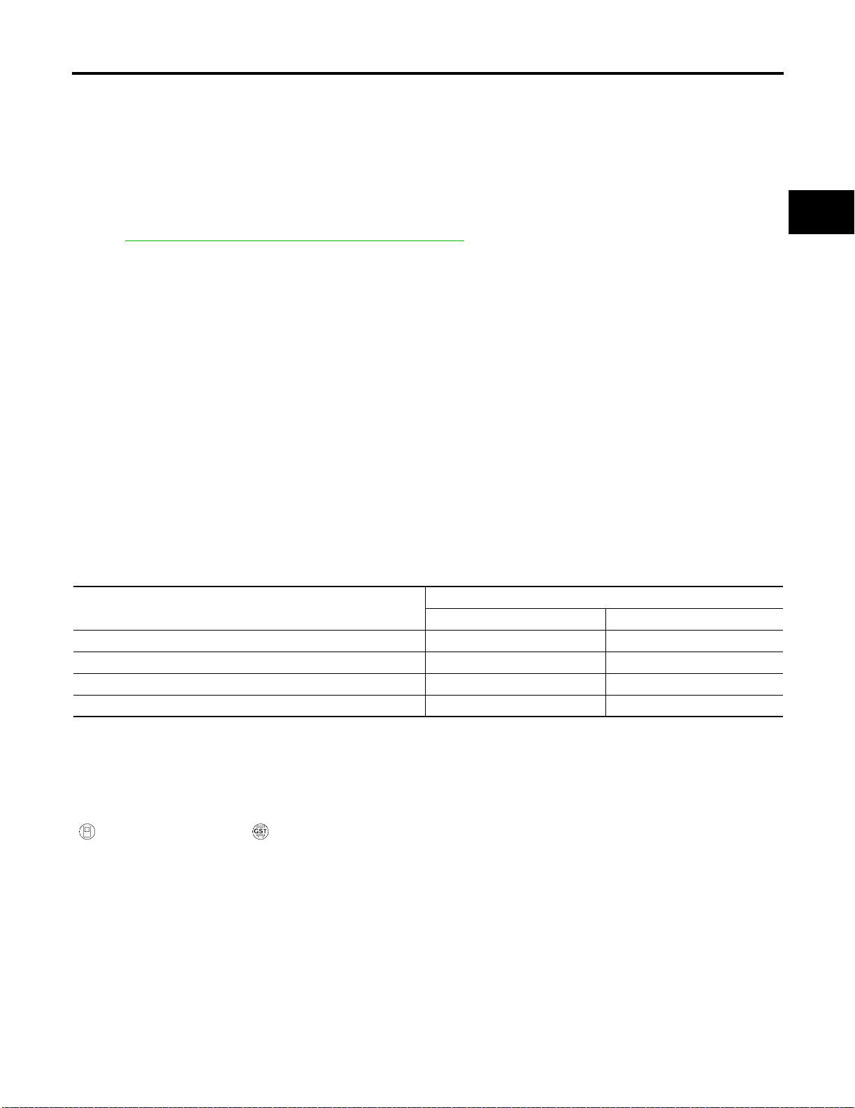
ON BOARD DIAGNOSTIC SYSTEM DESCRIPTION
[RE4F03B]
ON BOARD DIAGNOSTIC SYSTEM DESCRIPTION PFP:00000
Introduction ECS004D0
The A/T system has two self-diagnostic systems.
The first is the emission-related on board diagnostic system (OBD-II) performed by the TCM in combination
with the ECM. The malfunction is indicated by the MIL (malfunction indicator lamp) and is stored as a DTC in
the ECM memory but not the TCM memory.
The second is the TCM original self-diagnosis indicated by the O/D OFF indicator lamp. The malfunction is
stored in the TCM memory. The detected ite ms are overlap ped with OBD- II self-diagn ostic items . For detail,
refer to AT-42, "
SELF-DIAGNOSTIC RESULT TEST MODE" .
A
B
AT
OBD-II Function for A/T System ECS004D1
The ECM provides emission-rel ated on boa rd diagnos tic (OBD-II) functi ons for the A/T system. O ne function
is to receive a signal from the TCM used with OBD-related parts of the A/T system. The signal is sent to the
ECM when a malfunction occurs in the corresponding OBD-related part. The other function is to indicate a
diagnostic result by means of the MIL (malfunction indicator lamp) on the instrument panel. Sensors, switches
and solenoid valves are used as sensing elements.
The MIL automatically illuminates in One or Two Trip Detection Logic when a malfunction is sensed in relation
to A/T system parts.
One or Two Trip Detection Logic of OBD-II ECS004D2
ONE TRIP DETECTION LOGIC
If a malfunction is sensed during the first test drive, the MIL will illuminate and the malfunction will be stored in
the ECM memory as a DTC. The TCM is not provided with such a memory function.
TWO TRIP DETECTION LOGIC
When a malfunction is sensed during the first test drive, it is stored in the ECM memory as a 1st trip DTC
(diagnostic trouble code) or 1st trip freeze frame data. At this point, the MIL will not illuminate. — First Trip
If the same malfunction as that experienced during the first test drive is sensed during the second test drive,
the MIL will illuminate . — Seco nd Trip
A/T-related parts for which the MIL illuminates during the first or second test drive are listed below.
Items
Shift solenoid valve A — DTC: P0750 X
Shift solenoid valve B — DTC: P0755 X
Throttle position sensor or switch — DTC: P1705 X
Except above X
One trip detection Two trip detection
The “trip” in the “On e or Two Trip Detection Logic” me an s a dri vin g m od e i n w h ic h se lf -dia gn o sis is pe rfo r me d
during vehic le operation.
MIL
OBD-II Diagnostic Trouble Code (DTC) ECS004D3
HOW TO READ DTC AND 1ST TRIP DTC
DTC and 1st trip DTC can be read by the following methods.
( with CONSULT-II or GST) CONSULT-II or GST (Generic Scan Tool) Examples: P0705, P0710,
P0720, P0725, etc.
These DTCs are prescribed by SAE J2012.
(CONSULT-II also displays the malfunctioning component or system.)
● 1st trip DTC No. is the same as DTC No.
● Output of the diagnost ic trouble co de indicates th at the indica ted circuit has a malfunctio n. How-
ever, in case of the Mode II and GST they do not indicate whether the malfunction is still occurring
or occurred in the past and returned to normal.
CONSULT-II ca n identify them a s shown below. Therefore , using CONSULT-II (if available) is recommended.
D
E
F
G
H
I
J
K
L
M
AT-37
Page 82
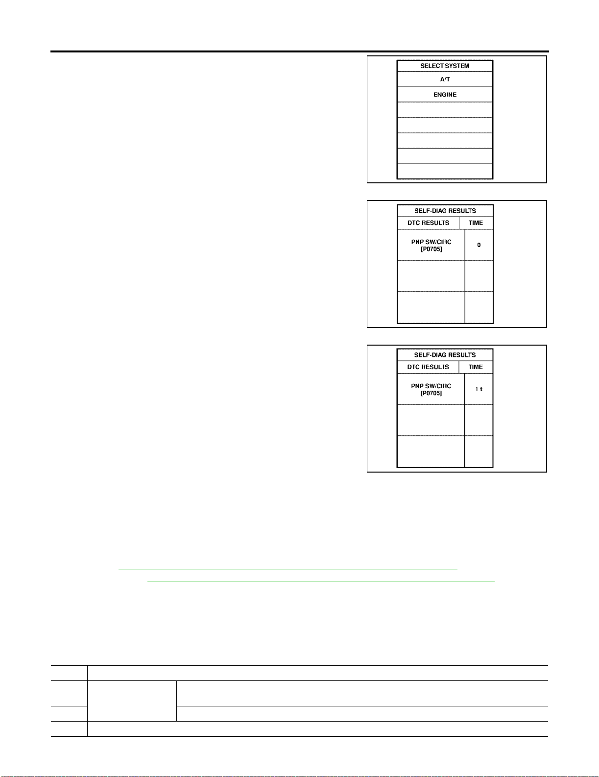
ON BOARD DIAGNOSTIC SYSTEM DESCRIPTION
A sample of CONSULT-II display for DTC and 1st trip DTC is shown.
DTC or 1st trip D TC o f a m al f un c tio n i s di sp layed in SELF DIAG NO SIS mode for “ENGINE” with CONSULT-II. Time data indicates how
many times the vehicle was driven after the last detection of a DTC.
If the DTC is being detected currently, the time data will be “0”.
[RE4F03B]
SAT014K
SAT015K
If a 1st trip DTC is stored in the ECM, the time data will be “1t”.
SAT016K
Freeze Frame Data and 1st Trip Fr eeze Frame Data
The ECM has a m emory function, which stores the driving co ndition such as fuel sy stem status, calculat ed
load value, engin e coolant temperature, short term fuel trim, long term fuel trim, engine speed and vehicle
speed at the moment the ECM detects a malfunction.
Data which are stored in the ECM mem ory, along with the 1st t rip DTC , are called 1st trip free ze fram e data,
and the data, stored t ogeth er wit h the D TC data , are c alled f reeze f rame data and displa yed on CONS ULT-II
or GST. The 1st trip freeze frame data can only be displayed on the CONSULT-II screen, not on the GST. For
detail, refer to EC-64, "
Calif. CA Model)] or EC-629, "
Model)].
Only one set o f freez e fram e da ta (either 1st tri p free ze fra me d ata of free ze fra me data) c an be store d in t he
ECM. 1st trip freez e frame data is s tored in the ECM me mory al ong w ith t he 1s t trip DT C. Th ere is no priori ty
for 1st trip freeze frame data and it is updated each time a different 1st trip DTC is detected. However, once
freeze frame data (2nd trip detection/MIL on) is stored in the ECM memory, 1st trip freeze frame data is no
longer stored. Remember, only one set of freeze frame data can be stored in the ECM.
The ECM has the following priorities to update the data.
Priority Items
1 Freeze frame data Misfire — DTC: P0300 - P0304
2 Excep t the above items (Includes A/T related items)
3 1st trip freeze f rame data
FREEZE FRAME DATA AND 1ST TRIP FREEZE FRAME DATA" [QG18DE (Except
FREEZE FRAME DATA AND 1ST TRIP FREEZE FRAME DATA" (Calif. CA
Fuel Injection System Function — DTC: P0171, P0172, P0174, P0175
AT-38
Page 83

ON BOARD DIAGNOSTIC SYSTEM DESCRIPTION
[RE4F03B]
Both 1st trip freeze frame data and freeze frame data (along with the DTCs) are cleared when the ECM memory is erased.
HOW TO ERASE DTC
The diagnostic tr ouble co de can be eras ed by CON SULT-II, GST or ECM DIAGNOST IC TEST MODE as follows.
● If the battery terminal is disconnected, the diagnostic trouble code will be lost within 24 hours.
● When you erase the DTC, using CONSULT-II or GST is easier and quicker than switching the mode
selector on t he ECM.
The following emi ssion-related diagnostic inf ormation is cleared from the ECM m emory when erasing DTC
related to OBD-II. For details, refer to EC-73, "
MATION" [QG18DE (Except Calif. CA Model)] or EC-637, "HOW TO ERASE EMISSION-RELATED DIAG-
NOSTIC INFORMATION" [QG18DE (Calif. CA Model)].
● Diagnostic trouble codes (DTC)
● 1st trip diagnostic trouble codes (1st trip DTC)
● Freeze frame data
● 1st trip freeze frame data
● System readiness test (SRT) codes
● Test values
HOW TO ERASE EMISSION-RELATED DIAGNOSTIC INFOR-
A
B
AT
D
E
F
HOW TO ERASE DTC (WITH CONSULT-II)
● If a DTC is displayed for both ECM and TCM, it needs to be erased for both ECM and TCM.
1. If the ignit ion swi tch stays “ON” after repair work, be sure to turn igniti on swit ch “OFF” once . Wait at least
10 seconds and then turn it “ON” (engine stopped) again.
2. Turn CONSULT-II “ON” and touch “A/T”.
3. Touch “SELF DIAGNOSIS”.
4. Touch “ERASE”. (The DTC in the TCM will be erased.) Then touch “BACK” twice.
5. Touch “ENGINE”.
6. Touch “SELF DIAGNOSIS”.
7. Touch “ERASE”. (The DTC in the ECM will be erased.)
G
H
I
J
K
L
M
AT-39
Page 84
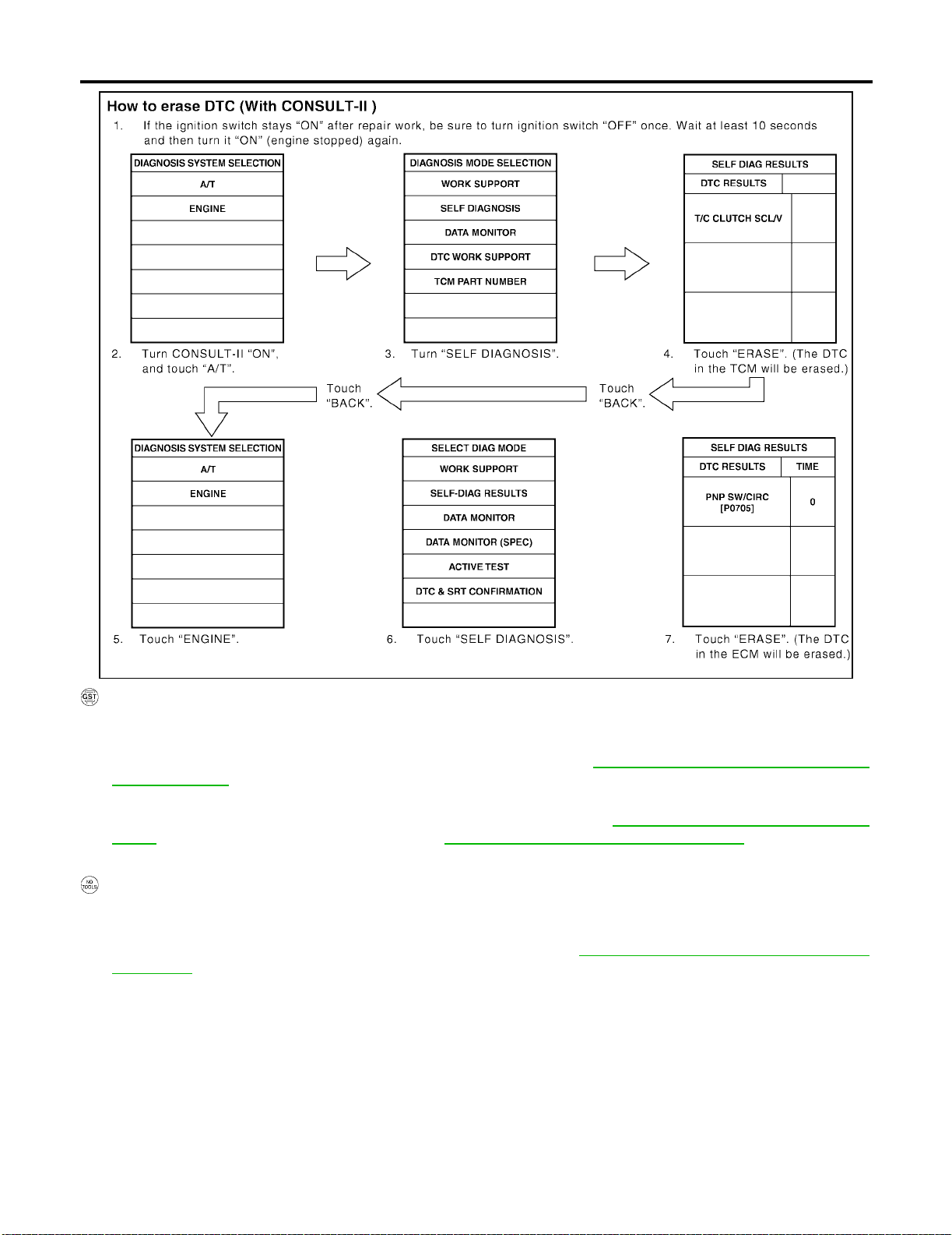
ON BOARD DIAGNOSTIC SYSTEM DESCRIPTION
[RE4F03B]
SAT286K
HOW TO ERASE DTC (WITH GST)
1. If the ignition s witch s tays “ON” aft er repair wo rk, be sure to tur n ignit ion swi tch “OFF” on ce. Wait at least
5 seconds and then turn it “ON” (engine stopped) again.
2. Perform “OBD-II Self-di agnostic Procedure (No Tools)”. Refer to AT-5 0 , "
dure (No Tools)" . (The engine warm- up st ep can be skipp ed w hen per formi ng th e diag nosis o nly to era se
the DTC.)
3. Select Mode 4 with Generic Scan Tool (GST). For details, refer to EC-74, "
GST)" [QG18DE (Except Calif. CA Model)] or EC-638, "How to Erase DTC ( With GST)" [QG18DE (Calif.
CA Model)].
OBD-II Self-diagnostic Proce-
How to Erase DTC ( With
HOW TO ERASE DTC (NO TOOLS)
1. If the ignition s witch s tays “ON” aft er repair wo rk, be sure to tur n ignit ion swi tch “OFF” on ce. Wait at least
5 seconds and then turn it “ON” (engine stopped) again.
2. Perform “TCM Self-diagnostic Procedure (No Tools)”. Refer to AT-5 0, "
(No Tools)" . (The engine wa rm- up step can be s ki pp ed w h en performing the di ag no sis only to eras e t he
DTC.)
TCM Self-diagnostic Procedure
AT-40
Page 85
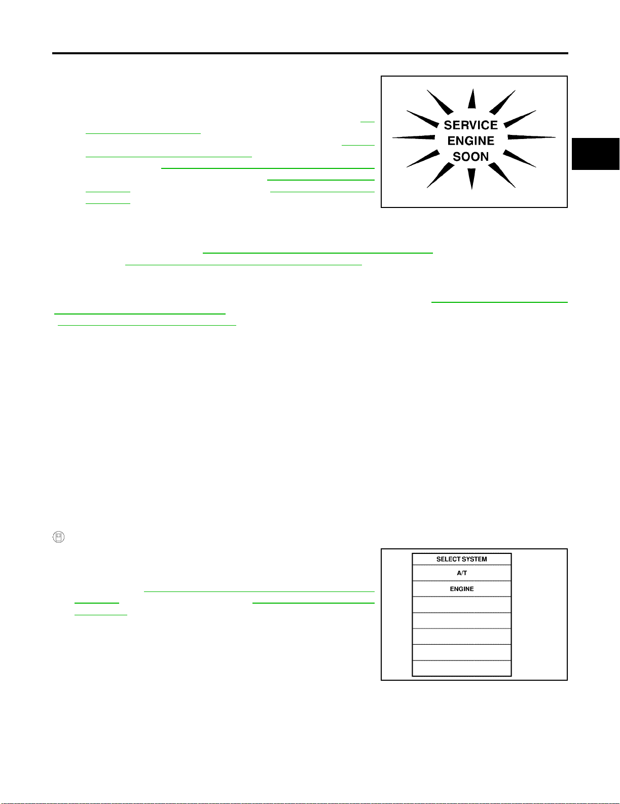
ON BOARD DIAGNOSTIC SYSTEM DESCRIPTION
[RE4F03B]
Malfunction Indicator Lamp (MIL) EC S004D4
1. The malfunction indicator lamp will light up when the ignition
switch is turned ON without the engine running. This is for
checking the lamp.
● If the malfuncti on i nd ic ato r l am p do es n ot l igh t up, refer to DI-
24, "WARNING LAMPS" .
(Or see MIL & CONSULT-II in EC section. Refer to EC-75,
"Malfunction In dicator Lamp (MIL)" [QG1 8DE (Except Calif.
CA Model)] or EC-639, "
Malfunction Indicator Lamp (MIL)"
[QG18DE (Calif. CA Model)], and EC-122, "CONSULT-II
Function" (Except Calif. CA Model)] or EC-686, "CONSULT-II
Function" [QG18DE (Calif. CA Model)].
SAT964I
2. When the engine is started, the malfunction indicator lamp
should go off.
If the lamp rema ins on, the on boar d diagnostic syst em has detected an emission-rel ated (OBD-II) malfunction. For detail, refer to EC-61, "
Model)] or EC-626, "
Emission-related Diagnostic Information" [QG18DE (Calif. CA Model)].
Emission-rel ate d Diag nost ic Info rma tio n" [QG18D E (Exc ept Cal if. C A
CONSULT-II ECS004D5
After performing “SELF-DIAGNOSTIC PROCEDURE (WITH CONSULT-II)” (AT-41, "SELF-DIAGNOSTIC
PROCEDURE (WITH CONSULT-II)" ), place check marks for results on the “DIAGNOSTIC WORKSHEET”,
(AT-57, "
NOTICE:
1. The CONSULT-II e le ct ric al l y dis pl a ys sh ift t imi ng an d l ock- up t imi ng (t ha t i s, o pe r atio n t imin g of e ach so le -
2. Shift sc hedu le (whic h impl ies ge ar posi tion) di sp laye d on CONS ULT-II and that indicate d in Serv ice Ma n-
– Actual shift schedu le ha s mo re or les s tol era nc e or allowa nc e,
– Shift schedul e indicated in Service Manual refers to the point where shifts start, and
– Gear position displayed on CONSULT-II indicates the point where shifts are completed.
3. Shift solenoid valve “A” or “B” is displayed on CONSULT-II at the start of shifting. Gear position is dis-
4. Additional CONSULT-II information can be found in the Operation Manual supplied with the CONSULT-II
DIAGNOSTIC WORKSHEET" ). Reference pages are provided followin g the items.
noid).
Check for time difference between actual shift timing and the CONSULT-II display. If the difference is
noticeable, mechanical parts (except solenoids, sensors, etc.) may be malfunctioning. Check mechanical
parts using applicable diagnostic procedures.
ual may differ slightly. This occurs because of the following reasons:
played upon completion of shift ing (which is computed by TCM).
unit.
A
B
AT
D
E
F
G
H
I
J
K
L
SELF-DIAGNOSTIC PROCEDURE (WITH CONSULT-II)
1. Turn on CONSULT-II and touch “ENGINE” for OBD-II detected
items or touch “A/T” for TCM s elf-diagnosis.
If A/T is not displayed, check TCM power supply and ground circuit. Refer to AT-111, "
SUPPLY" . If result is NG, refer to PG-2, "POWER SUPPLY
ROUTING" .
TROUBLE DIAGNOSIS FOR POWER
AT-41
M
SAT014K
Page 86
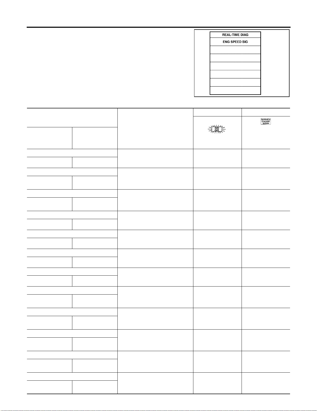
ON BOARD DIAGNOSTIC SYSTEM DESCRIPTION
2. Touch “SELF DIAG RESULTS”.
Display shows malfunction experienced since the last erasing
operation.
CONSULT-II performs “REAL TIME DIAG”.
Also, any malfunction detected while in this mode will be displayed at real time.
SELF-DIAGNOSTIC RESULT TEST MODE
Detected items
(Screen terms for CONSULT-II, “SELF
DIAGNOSIS” test mode)
Malfunction is detected when ...
“A/T” “ENGINE”
PNP switch circuit
—
PNP SW/CIRC
Revolution sensor
VHCL SPEED
SEN·A/T
VEH SPD SEN/CIR
AT
Vehicle speed sensor (Meter)
VHCL SPEED
SEN·MTR
—
A/T 1st gear function
—
A/T 1ST GR FNCTN
A/T 2nd gear function
—
A/T 2ND GR FNCTN
A/T 3rd gear function
—
A/T 3RD GR FNCTN
A/T 4th gear function
—
A/T 4TH GR FNCTN
A/T TCC S/V function (lock-up)
—
A/T TCC S/V
FNCTN
Shift solenoid valve A
SHIFT SOLENOID/V ASFT SOL A/CIRC
● TCM does not receive the correct
voltage signal (based on the gear
position) from the switch.
● TCM does not receive the proper
voltage signal from the sensor.
● TCM does not receive the proper
voltage signal from the sensor.
● A/T cannot be shifted to the 1st
gear position even if electrical circuit is good.
● A/T cannot be shifted to the 2nd
gear position even if electrical circuit is good.
● A/T cannot be shifted to the 3rd
gear position even if electrical circuit is good.
● A/T cannot be shifted to the 4th
gear position even if electrical circuit is good.
● A/T cannot perform lock-up even if
electrical circuit is good.
● TCM detects an improper voltage
drop when it tries to operate the
solenoid valve.
[RE4F03B]
TCM self-diagnosis OBD-II (DTC)
Available by O/D OFF
Available by malfunc-
indicator lamp or “A /T”
on CONSULT-II
— P0705
X P0720
X—
— P0731*1
— P0732*1
— P0733*1
— P0734*1
— P0744*1
X P0750
tion indicator lamp *2,
“ENGINE” on CON-
SULT-II or GST
SAT987J
Shift solenoid valve B
SHIFT SOLENOID/V BSFT SOL B/CIRC
Overrun clutch solenoid valve
OVERRUN
CLUTCH S/V
O/R CLUCH SOL/
CIRC
T/C clutch solenoid valve
T/C CLUTCH SOL/V TCC SOLENOID/
CIRC
● TCM detects an improper voltage
drop when it tries to operate the
solenoid valve.
● TCM detects an improper voltage
drop when it tries to operate the
solenoid valve.
● TCM detects an improper voltage
drop when it tries to operate the
solenoid valve.
AT-42
X P0755
X P1760
X P0740
Page 87
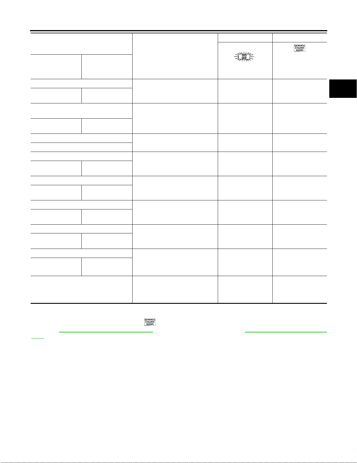
ON BOARD DIAGNOSTIC SYSTEM DESCRIPTION
[RE4F03B]
Detected items
(Screen terms for CONSULT-II, “SELF
DIAGNOSIS” test mode)
Malfunction is detected when ...
“A/T” “ENGINE”
Line pressure solenoid valve
LINE PRESSURE S/VL/PRESS SOL/CIRC
Throttle position sensor, Throttle position
switch
THROTTLE POSI
SEN
Engine speed signal
ENGINE SPEED SIG
A/T fluid temperature sensor
BATT/FLUID TEMP
SEN
TCM (RAM)
CONTROL UNIT
(RAM)
TCM (ROM)
CONTROL UNIT
(ROM)
TCM (EEP ROM)
CONT UNIT (EEP
ROM)
Initial start
INITIAL START
No failure
(NO SELF DIAGNOSTIC FAILURE INDICATED FURT HER TESTING MAY BE
REQUIRED**)
X: Applicable
—: Not applicable
*1: These malfunctions cannot be display ed by M IL if another malf unct i on is assi gned to MIL.
*2: Refer to EC-75, "
(MIL)" [QG18DE (Calif. CA Model)].
TP SEN/CIRC A/T
ATF TEMP SEN/
CIRC
—
—
—
—
Malfunction Indicato r Lamp (MIL)" [QG18D E (Except Calif. CA Model)] or EC-639, "Malfunction Indica tor Lamp
● TCM detects an improper voltage
drop when it tries to operate the
solenoid valve.
● TCM receives an excessivel y low
or high voltage from the sensor.
● TCM does not receive the proper
voltage signal from the ECM.
● TCM receives an excessivel y low
or high voltage from the sensor.
● TCM memory (RAM) is malfunc-
tioning.
● TCM memory (ROM) is malfunc-
tioning.
● TCM memory (EEP ROM) is mal-
functioning.
● This is not a malfunction message
(Whenever shutting off a power
supply to the TCM, this message
appears on the screen.)
● No failure has been detected.
TCM self-diagnosis OBD-II (DTC)
Available by O/D OFF
indicator lamp or “A/T”
on CONSULT-II
——
——
——
A
Available by malfunc-
tion indicator lamp *2,
“ENGINE” on CON-
SULT-II or GST
X P0745
B
AT
D
X P1705
E
X P0725
X P0710
F
G
H
I
J
X—
K
XX
L
M
AT-43
Page 88

ON BOARD DIAGNOSTIC SYSTEM DESCRIPTION
DATA MONITOR MODE (A/T)
Item Display
Vehicle speed sensor 1 (A/
T)
(Revolution sensor)
Vehicle speed sensor 2
(Meter)
Throttle position sensor THRTL POS
A/T fluid temperature sensor
Battery voltage BATTERY VOLT
Engine speed ENGINE SPEED
Overdrive control switch OVERDRIVE
PN position switch PN POSI SW
R position switch R POSITION SW
D position switch D POSITION SW
2 position switch 2 POSITION SW
1 position switch 1 POSITION SW
ASCD cruise signal ASCD CRUISE
ASCD OD cut signal ASCD OD CUT
VHCL/S SE·A/T
[km/h] or [mph]
VHCL/S
SE·MTR
[km/h] or [mph]
SEN
[V]
FLUID TEMP SE
[V]
[V]
[rpm]
SW
[ON/OFF]
[ON/OFF] X —
[ON/OFF] X —
[ON/OFF] X —
[ON/OFF] X —
[ON/OFF] X —
[ON/OFF]
[ON/OFF]
Monitor item
TCM
input sig-
nals
Main sig-
nals
X—
X—
X—
X—
X—
XX
X—
X—
X—
Description Remarks
● Vehicle speed computed
from signal of revolution
sensor is displayed.
● Vehicle speed computed
from signal of vehicle
speed sensor is displayed.
● Throttle position sensor
signal voltage is displayed.
● A/T fluid temperature
sensor signal voltage is
displayed.
● Signal voltage lowers as
fluid temperature rises.
● Source voltage of TCM is
displayed.
● Engine speed, computed
from engine speed signal,
is displayed.
● ON/OFF state computed
from signal of overdrive
control SW is displayed.
● ON/OFF state computed
from signal of PN position
SW is displayed.
● ON/OFF state computed
from signal of R position
SW is displayed.
● ON/OFF state computed
from signal of D position
SW is displayed.
● ON/OFF status, com-
puted from signal of 2
position SW, is displayed.
● ON/OFF status, com-
puted from signal of 1
position SW, is displayed.
● Status of ASCD cruise
signal is displayed.
ON ... Cruising state
OFF ... Normal running
state
● Status of ASCD O D
release signal is displayed.
ON ... OD released
OFF ... OD not released
[RE4F03B]
When racing engine in “N”
or “P” position with vehicle
stationary, CONSULT-II
data may not indicate 0 km/
h (0 mph).
Vehicle speed display may
not be accurate under
approx. 10 km/h (6 mph). It
may not indicate 0 km/h (0
mph) when vehicle is stationary.
Engine speed display may
not be accurate under
approx. 800 rpm. It may not
indicate 0 rpm even when
engine is not running.
● This is displayed even
when no ASCD is
mounted.
● This is displayed even
when no ASCD is
mounted.
AT-44
Page 89

ON BOARD DIAGNOSTIC SYSTEM DESCRIPTION
[RE4F03B]
Item Display
Kickdown switch KICKDOWN SW
[ON/OFF] X —
Closed throttle position
switch
CLOSED THL/
SW
[ON/OFF]
Wide open throttle position
switch
W/O THRL/PSW
[ON/OFF]
Gear position GEAR
Selector lever position SLCT LVR POSI
Vehicle speed VEHICLE
SPEED
[km/h] or [mph]
Stop lamp switch BRAKE SW
[ON/OFF]
Throttle position THROTTLE
POSI
[/8]
Line pressure duty LINE PRES DTY
[%]
Torq ue converter clutch
solenoid valve duty
TCC S/V DUTY
[%]
Shift solenoid valve A SHIFT S/V A
[ON/OFF]
Shift solenoid valve B SHIFT S/V B
[ON/OFF]
Monitor item
TCM
input sig-
nals
Main sig-
nals
X—
X—
—X
—X
—X
X—
—X
—X
—X
—X
—X
Description Remarks
● ON/OFF status, com-
puted from signal of kickdown SW, is displayed.
● ON/OFF status, com-
puted from signal of
closed th rottle posi tion
SW, is displayed.
● ON/OFF status, com-
puted from signal of wide
open throttle position SW,
is displayed.
● Gear position data used
for computation by TCM,
is displayed.
● Selector lever position
data, used for computation by TCM, is displayed.
● Vehicle speed data, used
for computation by TCM,
is displayed.
● ON/OFF status are dis-
played.
ON: Brake pedal is
depressed.
OFF: Brake pedal is
released.
● Throttle position data,
used for computation by
TCM, is displayed.
● Control value of line pres-
sure solenoid valve, computed by TCM from each
input signal, is displayed.
● Control value of torque
converter clutch solenoid
valve, computed by TCM
from each input signal, is
displayed.
● Control value of shift
solenoid valve A, computed by TCM from each
input signal, is displayed.
● Control value of shift
solenoid valve B, computed by TCM from each
input signal, is displayed.
● This is displayed even
when no kickdown switch
is equipped.
● A specific value used for
control is displayed if failsafe is activated due to
error.
● A specific value used for
control is displayed if failsafe is activated due to
error.
Control value of solenoid is
displayed even if solenoid
circuit is disconnected.
The “OFF” signal is displayed if solenoid circuit is
shorted.
A
B
AT
D
E
F
G
H
I
J
K
L
M
AT-45
Page 90
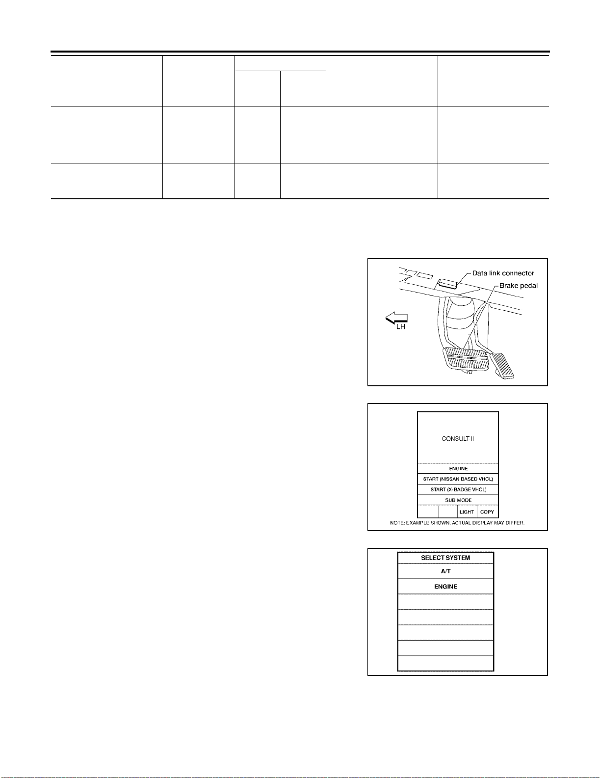
ON BOARD DIAGNOSTIC SYSTEM DESCRIPTION
Monitor item
Item Display
Overrun clutch solenoid
valve
Self-diagnosis display lamp
(O/D OFF indicator lamp)
X: Applicable
—: Not applicable
OVERRUN/C S/
V
[ON/OFF] — X
SELF-D DP LMP
[ON/OFF] — X
DTC WORK SUPPORT MODE WITH CONSULT-II
CONSULT-II Setting Procedure
1. Turn ignition switch “OFF”.
2. Connect CONSULT-II to Data link connector which is located in
left side lower dash pane l.
TCM
input sig-
nals
Main sig-
nals
● Control value of overrun
clutch solenoid valve
computed by TCM from
each input signal is displayed.
● Control status of O/D
OFF indicator lamp is displayed.
[RE4F03B]
Description Remarks
3. Turn ignition swit ch “ON”.
4. Touch “START (NISSAN BASED VHCL)”.
5. Touch “A/T”.
LAT136
BCIA0029E
SAT014K
AT-46
Page 91
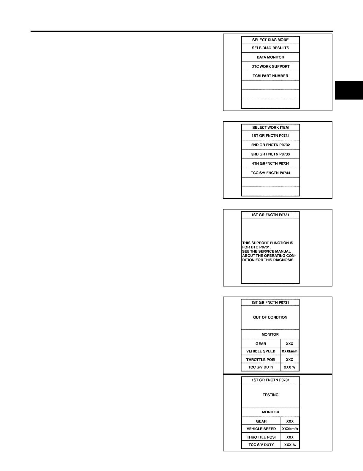
ON BOARD DIAGNOSTIC SYSTEM DESCRIPTION
6. Touch “DTC WORK SUPPORT”.
7. Touch select item menu (1ST, 2ND, etc.).
[RE4F03B]
A
B
AT
SAT971J
D
E
F
G
SAT018K
8. Touch “START”.
9. Perform driving test according to “DTC CONFIRMATION PROCEDURE” in “TROUBLE DIAGNOSIS FOR DTC”.
● When testing conditions are satisfied, CONSULT-II screen
changes from “OUT OF CONDITION” to “TESTING”.
SAT589J
SAT019K
H
I
J
K
L
M
SAT591J
AT-47
Page 92
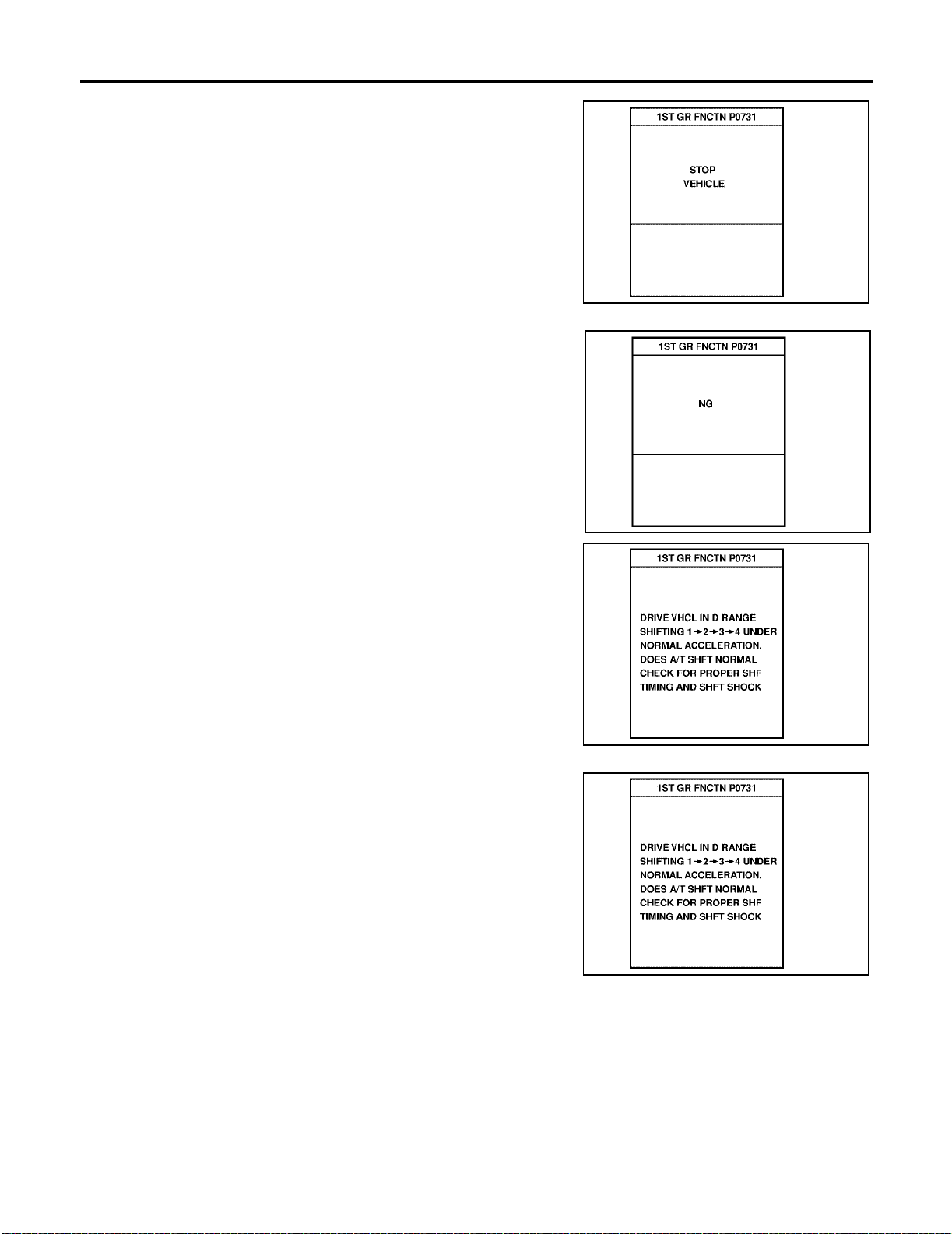
ON BOARD DIAGNOSTIC SYSTEM DESCRIPTION
10. Stop vehicle. If “NG” appears on the screen, malfunction may
exist. Go to “DIAGNOSTIC PROCEDURE”.
[RE4F03B]
SAT592J
11. Perform t est d riv e to chec k ge ar sh if t feel ing in ac cord ance wit h
instruction s displayed.
12. Touch “YES” or “NO”.
SAT593J
SAT594J
SAT595J
AT-48
Page 93
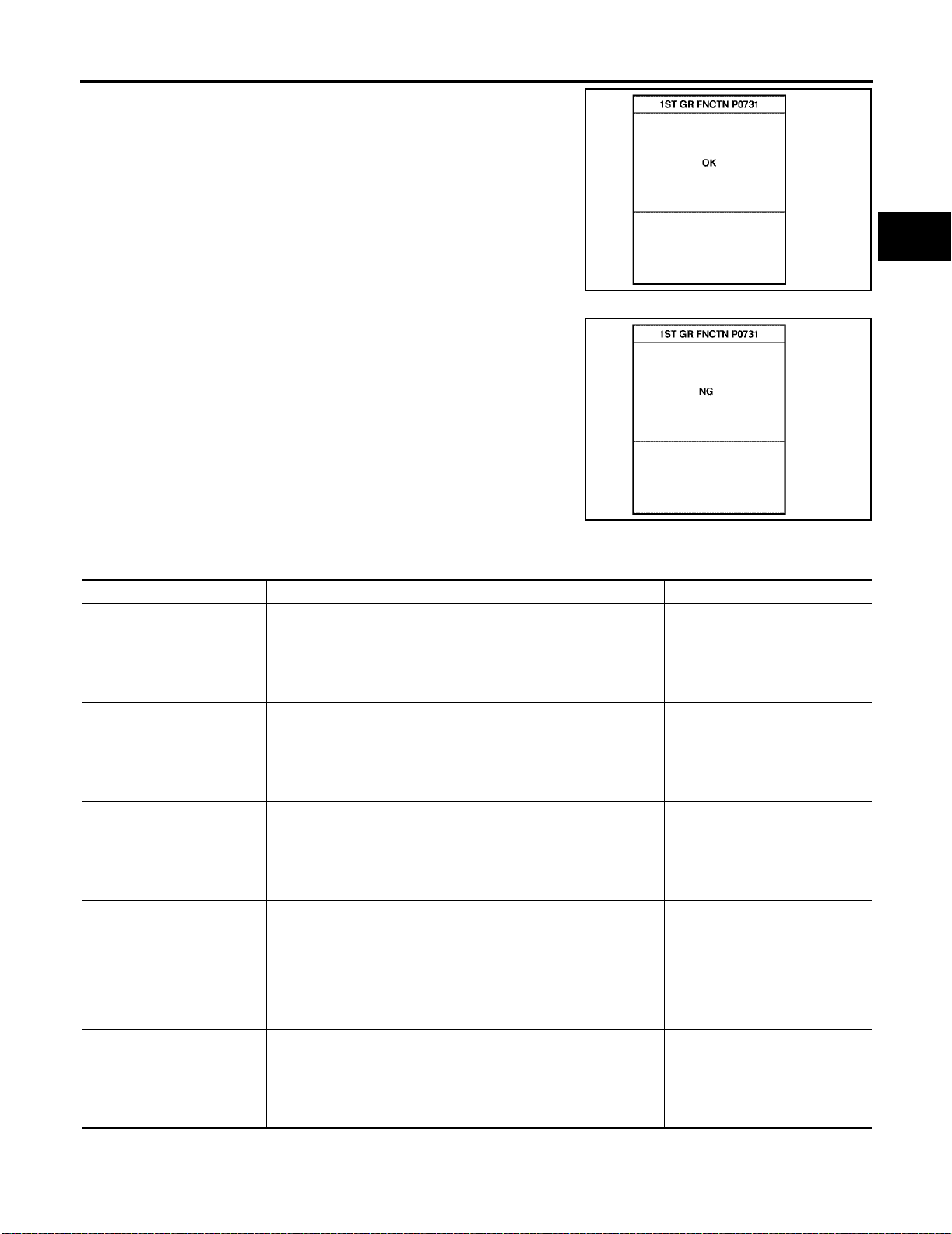
ON BOARD DIAGNOSTIC SYSTEM DESCRIPTION
[RE4F03B]
13. CONSULT-II proced ure ended.
If “NG” appears on the screen, a malfunction may exist. Go to “DIAGNOSTIC PROCEDURE”.
DTC WORK SUPPORT MODE
DTC work support item Description Check items (Possible cause)
1ST GR FNCTN P0731
2ND GR FNCTN P0732
3RD GR FNCTN P0733
4TH GR FNCTN P0734
TCC S/V FNCTN P0744
Following items for “A/T 1st gear function (P0731)” can be confirmed.
● Self-diagnosis status (whether the diagnosis is being conducted
or not)
● Self-diagnosis result (OK or NG)
Following items for “A/T 2nd gear functi on (P0 732)” can be confirmed.
● Self-diagnosis status (whether the diagnosis is being conducted
or not)
● Self-diagnosis result (OK or NG)
Following items for “A/T 3rd gear function ( P0733)” can be confirmed.
● Self-diagnosis status (whether the diagnosis is being conducted
or not)
● Self-diagnosis result (OK or NG)
Following items for “A/T 4th gear function (P0734)” can be confirmed.
● Self-diagnosis status (whether the diagnosis is being conducted
or not)
● Self-diagnosis result (OK or NG)
Following items for “A/T TCC S/V function (lock -up ) (P0 744)” can
be confirmed.
● Self-diagnosis status (whether the diagnosis is being conducted
or not)
● Self-diagnosis result (OK or NG)
● Shift solenoid valve A
● Shift solenoid valve B
● Each clutch
● Hydraulic control circuit
● Shift solenoid valve B
● Each clutch
● Hydraulic control circuit
● Shift solenoid valve A
● Each clutch
● Hydraulic control circuit
● Shift solenoid valve A
● Shift solenoid valve B
● Overrun clutch solenoid valve
● Line pressure solenoid valve
● Each clutch
● Hydraulic control circuit
● Torque converter clutch sole-
noid valve
● Each clutch
● Hydraulic control circuit
A
B
AT
SAT596J
D
E
F
G
SAT593J
H
I
J
K
L
M
AT-49
Page 94
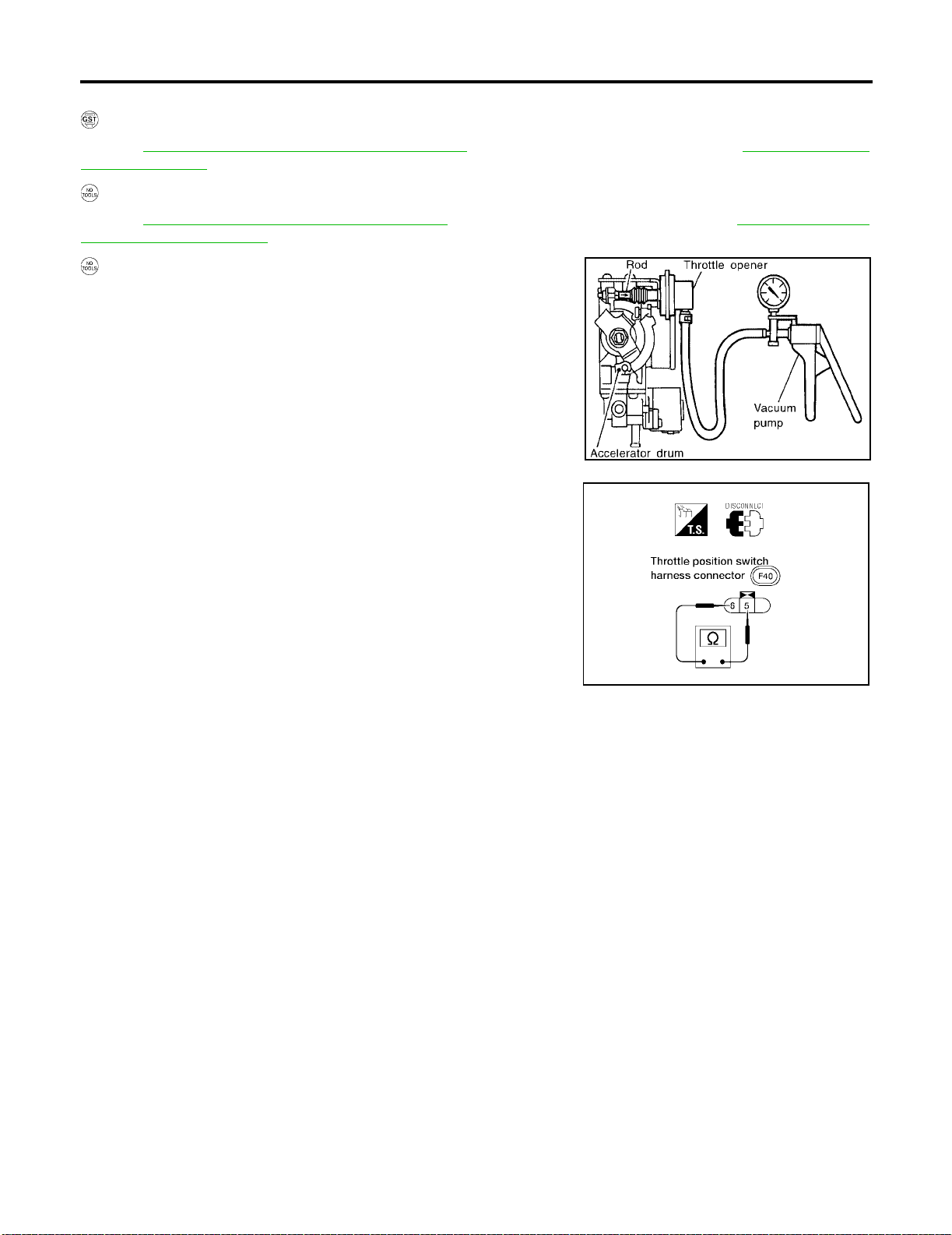
ON BOARD DIAGNOSTIC SYSTEM DESCRIPTION
[RE4F03B]
DIAGNOSTIC PROCEDURE WITHOUT CONSULT-II
OBD-II Self-diagnostic Procedure (With GST)
Refer to EC-137, "Generic Scan Tool (GST) Function" [QG18DE (Except Calif. CA Model)], EC-701, "Generic
Scan Tool (GST)" [QG18DE (Calif. CA Model)].
OBD-II Self-diagnostic Procedure (No Tools)
Refer to EC-75, "Malfunction Indicator Lamp (MIL)" [QG18DE (Except Calif. CA Model)] or EC-639, "Malfunc-
tion Indicator Lamp (MIL)" [QG18DE (Calif. CA Model)].
TCM Self-diagnostic Proced ure (No Tools)
SAT491J
Preparation
1. Turn ignition switch to “OFF” position.
2. Connect the h andy type vacu um pum p to the t hrot tle opener and
apply vacuum −25.3 kPa (−190 mmHg, −7.48 inHg).
3. Disconnect the throttle position switch harness connector .
4. Turn ignition switch to “ON” position.
5. Check continuity of the closed throttle position switch.
Continuity should
exist.
(If continuity does not exist, check throttle opener and closed throttle position switch. Then
increase vacuum until closed throttle position switch shows continuity.)
6. Go to test group 1, "CHECK O/D OFF INDICATOR LAMP".
LAT153
AT-50
Page 95
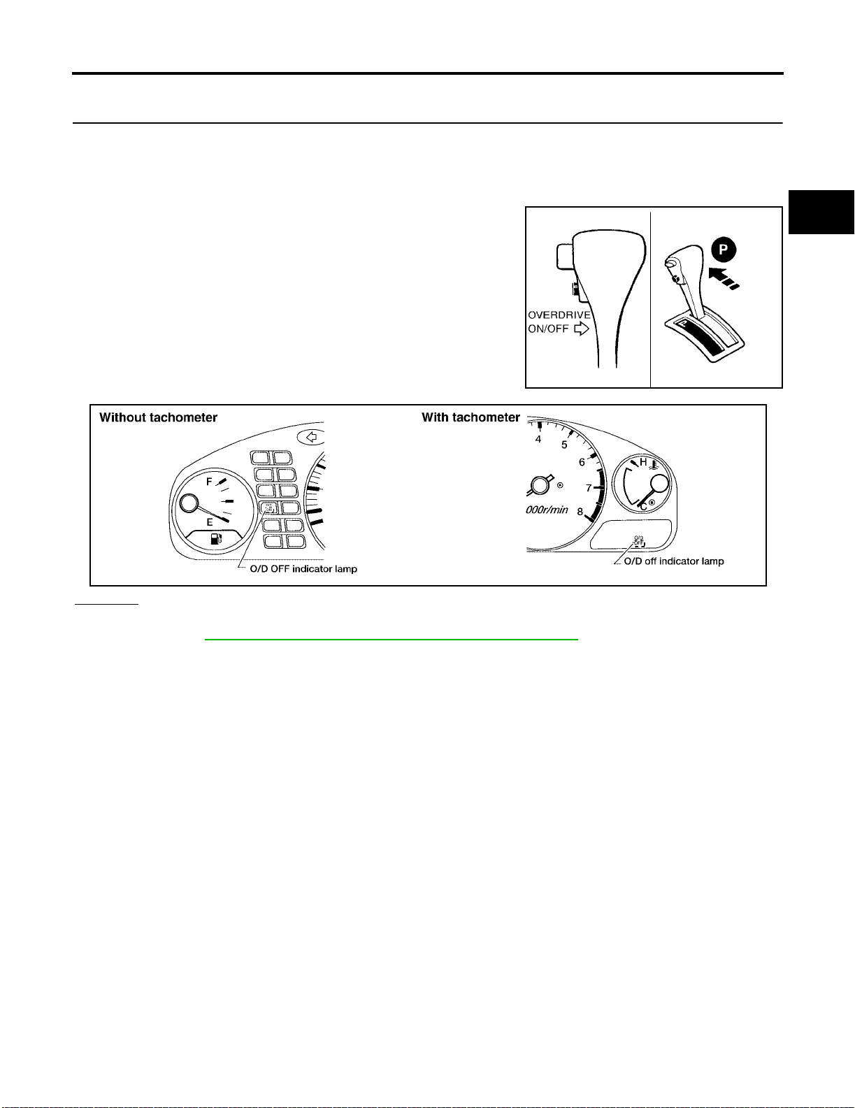
ON BOARD DIAGNOSTIC SYSTEM DESCRIPTION
[RE4F03B]
1. CHECK O/D OFF INDICATOR LAMP
1. Move A/T selector lever to “P” position.
Start the engine.
Warm engine to normal operating tem perature.
2. Turn ignition switch to “OFF” position.
3. Wait 5 seconds.
4. Turn ignition switch to “ON” position.
(Do not start engine.)
5. Does O/D OFF indicator lamp come on fo r about 2 seconds?
SAT967I
A
B
AT
D
E
F
G
H
Yes or No
Yes >> GO TO 2.
No >> GO TO AT- 215, "
I
LAT154
J
1. O/D OFF Indicator Lamp Does Not Come On" .
K
L
M
AT-51
Page 96
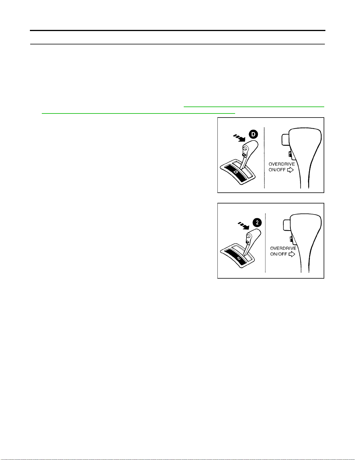
ON BOARD DIAGNOSTIC SYSTEM DESCRIPTION
[RE4F03B]
2. JUDGEMENT PROCEDURE STEP 1
1. Turn ignition switch to “OFF” position.
2. Tur n ignition switch to “ACC” position.
3. Move A/T selector lever from “P” to “D” position.
4. Turn ignition switch to “ON” position.
(Do not start engine.)
5. Depress and h old overdrive control switch (the O/ D OFF indicator lamp will be “ON”) until directed to
release the switch.
If O/D OFF indicator lamp doe s not come on, go to AT-24 5 , "
(PNP, Overdrive Control and Throttle Position Switches Circuit Checks)" .
6. Turn ignition switch to “OFF” position.
7. Turn ignition switch to “ON” position.
(Do not start engine.)
8. Release the overdrive control switch (the O/D OFF indicator
lamp will be “OFF”).
9. Wait 2 seconds.
10. Move A/T select or lever to “2” position.
11. Depress and release the ove rdrive control s witch (the O/D OFF
indicator lamp will be “ON”).
21. TCM Self-diagnos is Does Not Activate
SAT968I
12. Depress and hold the overdrive control switch (the O/D OFF
indicator lamp will be “OFF”) until directed to release the switch.
>> GO TO 3.
SAT969I
AT-52
Page 97
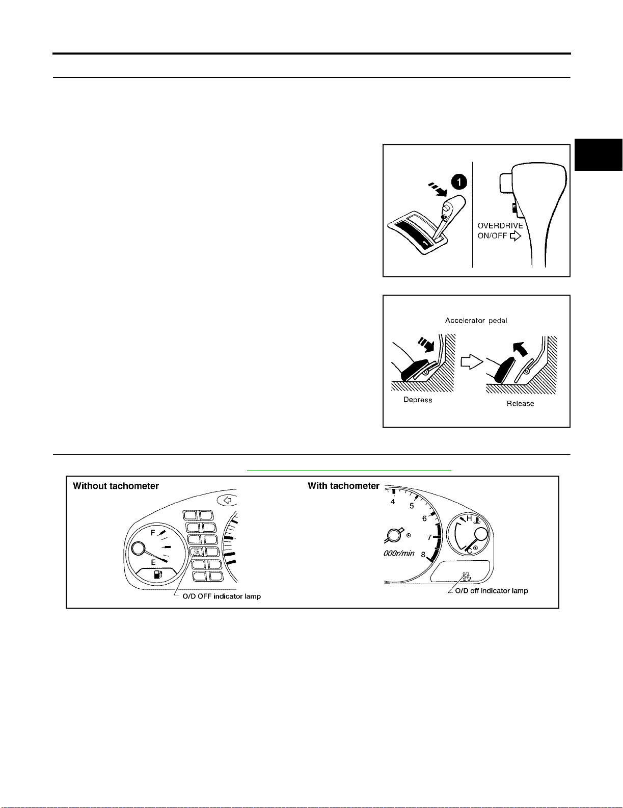
ON BOARD DIAGNOSTIC SYSTEM DESCRIPTION
[RE4F03B]
3. JUDGEMENT PROCEDURE STEP 2
1. Move A/T selector lever to “1” position.
2. Release the overd rive control switch.
3. Depress and releas e the overdriv e control switch (the O/D OFF indicator lamp will be “ON”).
4. Depress and releas e the overdriv e control switch (the O/D OFF indicator lamp will be “OFF”).
5. Depress and hold the overdrive control switch (the O/D OFF
indicator lamp will be “ON”) until directed to release the switch.
6. Depress accelerator pedal fully and release.
7. Release the overdrive control switch (the O/D OFF indicator
lamp will begin to flash “ON” and “OFF”).
>> GO TO 4.
SAT970I
A
B
AT
D
E
F
G
H
4. CHECK SELF-DIAGNOSIS CODE
Check O/D OFF indicator lamp. Refer to AT-54, "
>> DIAGNOSIS END
I
SAT981F
J
Judgement of Self-diagnosis Code" .
K
L
M
LAT154
AT-53
Page 98
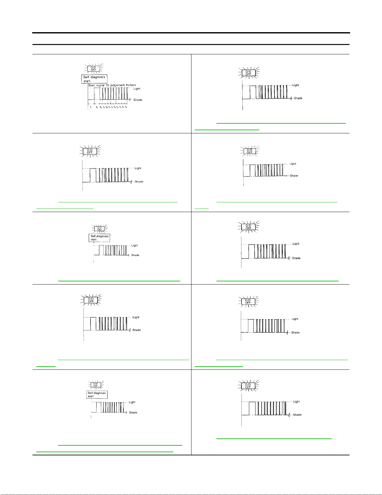
ON BOARD DIAGNOSTIC SYSTEM DESCRIPTION
Judgement of Self-diagnosis Code
O/D OFF indicator lamp:
All judgement flickers are the same.
WCIA0073E WCIA0074E
All circuits that can be confirmed by self-diagnos is are O K.
2nd judgement flicker is longer than others.
WCIA0075E WCIA0076E
Vehicle speed sensor circuit is short-circuited or disconnected.
Þ Go to AT-202, "
SPEED SENSOR·MTR" .
4th judgement flicker is longer than others.
DTC VHCL SPEED SEN·MTR VEHICLE
[RE4F03B]
1st judgement flicker is longer than others.
Revolution sensor circuit is short-circui te d or disconnected.
Þ Go to AT-124, "
(REVOLUTION SENSOR)" .
3rd judgement flicker is longer than others.
Throttle position sensor circuit is short-circ uited or disconnected.
Þ Go to AT-184, "
SOR" .
5th judgement flicker is longer than others.
DTC P0720 VEHICLE SPEED SENSOR·A/T
DTC P1705 THROTTLE POSITION SEN-
WCIA0077E WCIA0078E
Shift solenoid valve A circuit is short-circuited or disconnected.
Þ Go to AT-176, "
6th judgement flicker is longer than others.
Overrun clutch solenoid valve circu it is short- ci rcu ited or disc onnected.
Þ Go to AT-192, "
VALVE" .
8th judgement flicker is longer than others.
A/T fluid temperature sensor is disconnec te d or TCM pow er
source circuit is damaged.
Þ Go to AT-196, "
TEMP SENSOR CIRCUIT AND TCM POWER SOURCE)" .
DTC P0750 SHIFT SOLENOID VALVE A" .
WCIA0079E WCIA0080E
DTC P1760 OVERRUN CLUTCH SOLENOID
WCIA0081E WCIA0082E
DTC BATT/FLUID TEMP SEN (A/T FLUID
Shift solenoid valve B circuit is short-circuited or disco nnected.
Þ Go to AT-180, "DTC P0755 SHIFT SOLENOID VALVE B" .
7th judgement flicker is longer than others.
Torque converter clutch solenoid valve circuit is short- circuited or
disconnected.
Þ Go to AT -155, "
SOLENOID VALVE" .
9th judgement flicker is longer than others.
Engine speed signal circuit is short-circuited or disconnected.
Þ Go to AT-128, "DTC P0725 ENGINE SPEED SIGNAL" .
DTC P0740 TORQUE CONVERTER CLUTCH
AT-54
Page 99
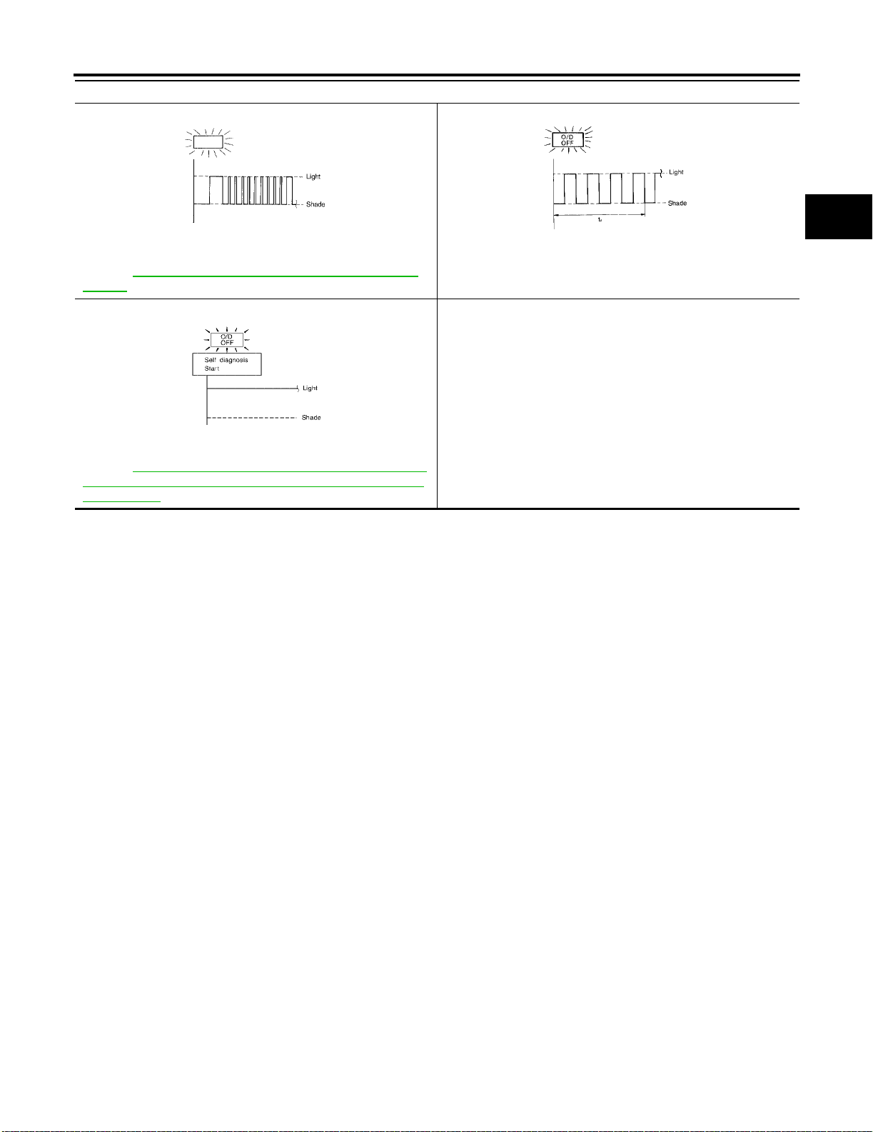
ON BOARD DIAGNOSTIC SYSTEM DESCRIPTION
[RE4F03B]
O/D OFF indicator lamp:
10th judgement flicker is longer than others.
WCIA0083E WCIA0084E
Line pressure solenoid valve circuit is short-circuited or disconnected.
Þ Go to A T-170, "
VALVE" .
Lamp comes on.
PNP switch, overdrive contro l s witch or throttle position switch circuit is disconnected or TCM is damaged.
Þ Go to A T-245, "
(PNP, Overdrive Contr ol and Throt tle Posi tion Switches Circuit Checks)" .
t1 = 2.5 seconds t2 = 2.0 seconds t3 = 1.0 second t4 = 1.0 second
DTC P0745 LINE PRESSURE SOLENOID
WCIA0085E
21. TCM Self-diagnosis Does Not Activate
Flickers as shown below.
Battery power is low.
Battery has been disconnected for a long time.
Battery is connected conversely.
(When reconnecting TCM connect or s. — Thi s is not a proble m .)
A
B
AT
D
E
F
G
H
M
I
J
K
L
AT-55
Page 100
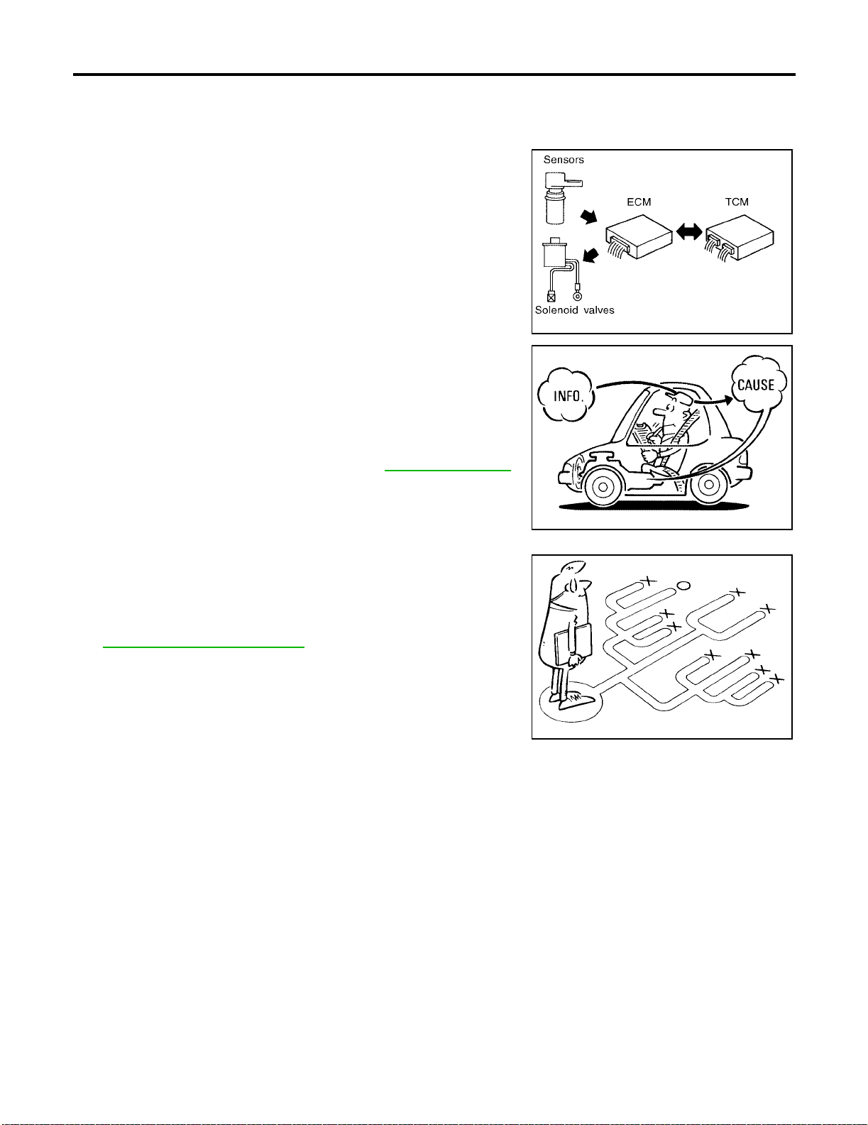
TROUBLE DIAGNOSIS — INTRODUCTION
[RE4F03B]
TROUBLE DIAGNOSIS — INTRODUCTION PFP:00000
Introduction ECS004D6
The TCM receiv es a signal from the vehicl e speed sensor, throttle
position sensor or PNP switch and provides shift control or lock-up
control via A/T solenoid valves.
The TCM also communicates with the ECM by means of a signal
sent from sensing elements used with the OBD-related parts of the
A/T system for malfu nction-diagnostic purpo ses. The TCM is capable of diagno si ng malfunction in g parts wh ile th e EC M can store malfunctions in its memory.
Input and output signals must always be correct and stable in the
operation of the A/T system. The A/T system must be in good operating condition and be free of valve seizure, solenoid valve malfunction, etc.
It is much more difficult to diagn ose a problem th at occurs intermi ttently rather than continuously. Most intermittent problems are
caused by po or electric connectio ns o r i mp roper wiring. In t hi s ca se ,
careful checking of suspected circuits may help prevent the replacement of good parts.
A visual check only may not find the cause of the problems. A road
test with CONSULT-II (or GST) or a circuit tester connec ted should
be performed. Follow the “Work Flow”. Refer to AT-60, "
Work Flow" .
AAT473A
Before undertaking a ctual checks, take a fe w minutes to talk with a
customer who approaches with a driveability complaint. The customer can supply good information about such problems, especially
intermittent ones. Find out what symptoms are present and under
what condition s they occur. A “Diagnostic Worksheet” l ik e t he ex am ple (AT-58, "
Diagnostic Worksheet" ) should be used.
Start your diagnosis by looking for “conventional” problems first. This
will help troubleshoot driveability problems on an electronically controlled engine vehicle.
Also check related Service bulletins for information.
SAT632I
SEF234G
AT-56
 Loading...