

Page 1

AIR CONDITIONER
Revision: October 2008
2009 Quest
A
B
SECTION MTC
MANUAL AIR CONDITIONER
CONTENTS
SERVICE INFORMATION ............................3
PRECAUTIONS ...................................................3
Precaution for Supplemental Restrain t System
(SRS) "AIR BAG" and "SEAT BELT PRE-TEN-
SIONER" ...................................................................
Precaution for Working with HFC-134a (R-134a) ......3
Contaminated Refrigerant .........................................3
General Refrigerant Precaution ................................4
Precaution for Leak Detection Dye ...........................4
A/C Identification Label .............................................4
Precaution for Refrigerant Connectio n ......................4
Precaution for Service of Compressor ......................8
Precaution for Service Equipment .............................9
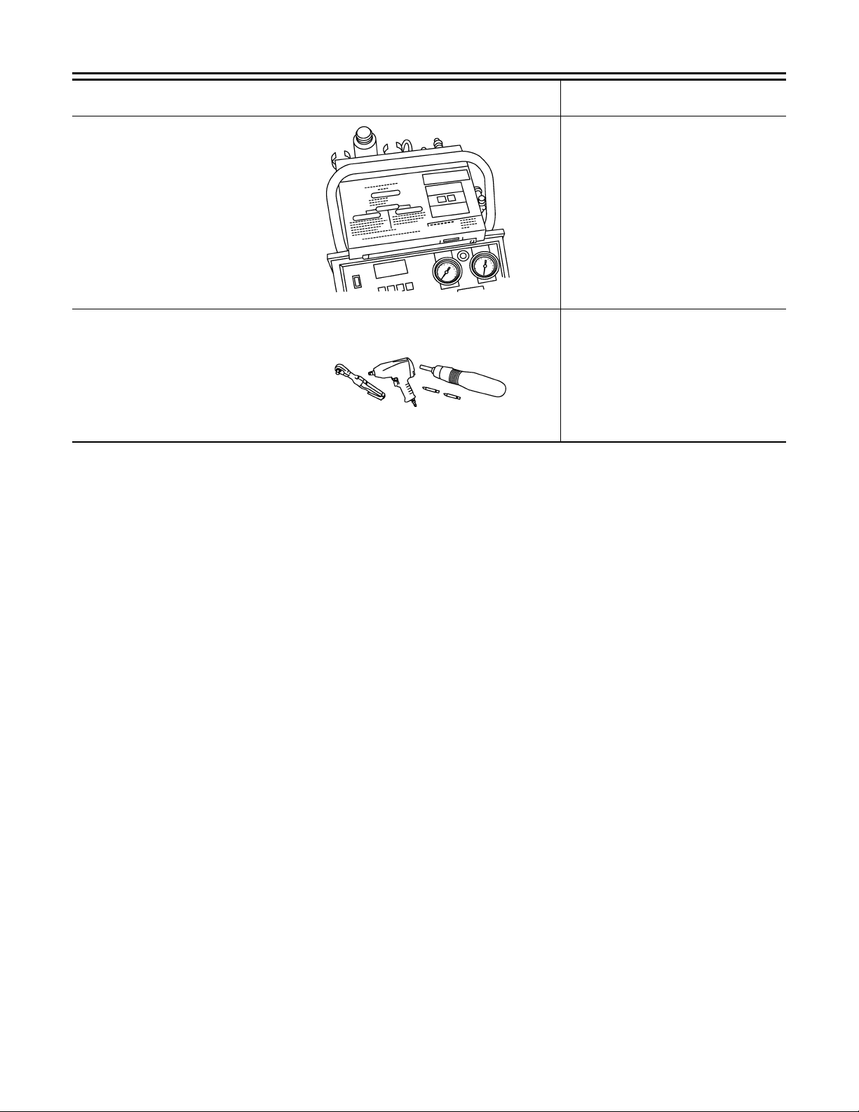
PREPARATION ..................................................11
Special Service Tool .............................. ... ... .... .......11
HFC-134a (R-134a) Service Too l a nd Eq uipment ....11
Commercial Service Tool ........................................13
REFRIGERATION SYSTEM ..............................15
Refrigerant Cycle ....................................................15
Refrigerant System Protection ................................15
Component Part Location ................... ... ... ..............16
OIL ......................................................................19
Maintenance of Oil Quantity in Compressor ...........19
AIR CONDITIONER CONTROL .........................21
Description ..............................................................21
Operation ................................................................21
Description of Control System .................................22
Control Operation ....................................................23
Discharge Air Flow ..................................................25
System Description .................................................26
CAN Communication System Description ...............26
TROUBLE DIAGNOSIS .....................................27
CONSULT-III Function (HVAC) ...............................27
CONSULT-III Function (BCM) .................................28
How to Perform Trouble Diagnosis for Quick and
Accurate Repair ......................................................
29
Component Parts and Harness Connector Loca-
tion ................................ ............................. ..............
Schematic ........................ ................................ ........34
Wiring Diagram - A/C,M - ........................................35
Front Air Control Terminal and Reference Value ....43
3
A/C System Self-Diagnosis Function .......................44
Operational Check (Front) .......................................45
Operational Check (Rear) ........................................47
Power Supply and Ground Circuit for Front Air
Control ............................. ........................................
Mode Door Motor Circuit .........................................50
Air Mix Door Motor Circuit .......................................54
Intake Door Motor Circuit .........................................63
Defroster Door Motor Circuit ....................................67
Front Blower Motor Circuit .......................................69
Rear Blower Motor Circuit .......................................75
Rear Temperature Control Circuit ...........................84
Magnet Clutch Circuit ..............................................90
Insufficient Cooling ..................................................94
Insufficient Heating ................................................101
Heater Pump Circuit ........... ... .... ... ... ... ...................102
Noise .....................................................................105
Self-Diagnosis .......................................................107
Ambient Sensor Circuit ..........................................108
Intake Sensor Circuit .......... ... .... ... ... ......................110
CONTROL UNIT ..............................................113
Removal and Installation .......................................113
AMBIENT SENSOR ........................................ 115
Removal and Installation .......................................115
INTAKE SENSOR ........................................... 116
Removal and Installation .......................................116
BLOWER MOTOR ..........................................118
Component ................... .........................................118
Removal and Installation .......................................119
IN-CABIN MICROFILTER ...............................120
Removal and Installation .......................................120
C
D
E
F
30
G
H
48
I
MTC
K
L
M
N
O
P
MTC-1
Page 2

HEATER & COOLING UNIT ASSEMBLY ....... 121
Revision: October 2008
2009 Quest
Component ............................................................121
Removal and Installation .......................................122
HEATER CORE ............................................... 124
Component ............................................................124
Removal and Installation .......................................125
HEATER PUMP ............................................... 127
Removal and Installation .......................................127
DEFROSTER DOOR MOTOR ......................... 128
Removal and Installation .......................................128
INTAKE DOOR MOTOR .................................. 129
Component ............................................................129
Removal and Installation .......................................130
MODE DOOR MOTOR .................................... 132
Removal and Installation .......................................132
AIR MIX DOOR MOTOR .................................. 134
Component ............................................................134
Removal and Installation .......................................134
VARIABLE BLOWER CONTROL ................... 136
Component ............................................................136
Removal and Installation .......................................137
REFRIGERANT LINES .....................................143
HFC-134a (R-134a) Service Procedure ................ 143
Component ........................................................... 145
Removal and Installation for Compressor .............147
Removal and Installation for Compressor Clutch ..147
Removal and Installation for Low-Pressure Flexi-
ble Hose ........................ ... ... ... ...............................
Removal and Installation for High-pressure Flexi-
ble Hose ........................ ... ... ... ...............................
Removal and Installation for High-pressure Pipe .. 151
Removal and Installation for High/Low-Pressure
Pipe .................................. .....................................
Removal and Installation for Refrigerant Pressure
Sensor ........................... ............. ............ .......... .....
Removal and Installation for Condenser ...............155
Removal and Installation for Front Evaporator .....157
Removal and Installation for Rear Evaporator ......159
Removal and Installation for Front Expansion
Valve .....................................................................
Removal and Installation for Rear Expansion
Valve .....................................................................
Checking of Refrigerant Leaks ..............................161
Checking System for Leaks Using the Fluorescent
Dye Leak Detector ................................................
Dye Injection . ... ... ... ... ....................................... ... .. 161
Electronic Refrigerant Leak Detector ....................162
150
150
151
155
160
160
161
DUCTS AND GRILLES .................................... 138
Component ............................................................138
Removal and Installation .......................................141
SERVICE DATA AND SPECIFICATIONS
(SDS) ................................................................
Service Data and Specification (SDS) ..................165
165
MTC-2
Page 3

< SERVICE INFORMATION >
Revision: October 2008
2009 Quest
PRECAUTIONS
SERVICE INFORMATION
PRECAUTIONS
Precaution for Supplemental Restraint System (SRS) "AIR BAG" and "SEAT BELT PRE-TENSIONER" INFOID:0000000004277527
The Supplemental Restraint System such as “AIR BAG” and “SEAT BELT PRE-TENSIONER”, used along
with a front seat belt, helps to reduce the risk or severity of injury to the driver and front passenger for certain
types of collision. This system includes seat belt switch inputs and dual stage front air bag modules. The SRS
system uses the seat belt switches to determine the front air bag deployment, and may only deploy one front
air bag, depending on the severity of a collision and whether the front occupants are belted or unbelted.
Information necessary to service the system safely is included in the SRS and SB section of this Service Manual.
WARNING:
• To avoid rendering the SRS inoperative, which could increase the risk of personal injury or death in
the event of a collision which would result in air bag inflation, all maintenance must be performed by
an authorized NISSAN/INFINITI dealer.
• Improper maintenance, including incorrect removal and installation of the SRS, can lead to personal
injury caused by unintentional activation of the system. For removal of Spiral Cable and Air Bag
Module, see the SRS section.
• Do not use electrical test equipment on any circuit related to the SRS unless instructed to in this
Service Manual. SRS wiring harnesses can be identified by yellow and/or orange harnesses or harness connectors.
Precaution for Working with HFC-134a (R-134a) INFOID:0000000004277528
A
B
C
D
E
F
G
H
WARNING:
• CFC-12 (R-12) refrigerant and HFC-134a (R-134a) refrigerant are not compatible. If the refrigerants
are mixed compressor failure is likely to occur. Refer to MTC-3, "Contaminated Refrigerant"
determine the purity of HFC-134a (R-134a) in the vehicle and recovery tank, use refrigerant recovery/
recycling equipment and refrigerant identifier.
• Use only specified oil for the HFC-134a (R-134a) A/C system and HFC-134a (R-134a) components. If
oil other than that specified is used, compressor failure is likely to occur.
• The specified HFC-134a (R-134a) oil rapidly absorbs moisture from the atmosphere. The following
handling precautions must be observed:
- When removing refrigerant components from a vehicle, immediately cap (seal) the component to
minimize the entry of moisture from the atmosphere.
- When installing refrigerant components to a vehicle, do not remove the caps (unseal) until just
before connecting the components. Connect all refrigerant loop components as quickly as possible
to minimize the entry of moisture into system.
- Only use the specified oil from a sealed container. Immediately reseal containers of oil. Without
proper sealing, oil will become moisture saturated and should not be used.
- Avoid breathing A/C refrigerant and oil vapor or mist. Exposure may irritate eyes, nose and throat.
Remove HFC-134a (R-134a) from the A/C system using certified service equipment meeting requirements of SAE J2210 [HFC-134a (R-134a) recycling equipment] or J2209 [HFC-134a (R-134a) recycling
equipment]. If accidental system discharge occurs, ventilate work area before resuming service.
Additional health and safety information may be obtained from refrigerant and oil manufacturers.
- Do not allow refrigerant oil to come in contact with styrofoam parts. Damage may result.
. To
Contaminated Refrigerant INFOID:0000000004277529
If a refrigerant other than pure HFC-134a (R-134a) is identified in a vehicle, your options are:
• Explain to the customer that environmental regulations prohibit the release of contaminated refrigerant into
the atmosphere.
• Explain that recovery of the contaminated refrigerant could damage your service equipment and refrigerant
supply.
• Suggest the customer return the vehicle to the location of previous service where the contamination may
have occurred.
• If you choose to perform the repair, recover the refrigerant using only dedicated equipment and contain-
ers. Do not recover contaminated refrigerant into your existing service equipment. If your facility does
I
MTC
K
L
M
N
O
P
MTC-3
Page 4

PRECAUTIONS
Revision: October 2008
2009 Quest
< SERVICE INFORMATION >
not have dedicated recovery equipment, you may contact a local refrigerant product retailer for available service. This refrigerant must be disposed of in accordance with all federal and local regulations. In addition,
replacement of all refrigerant system components on the vehicle is recommended.
• If the vehicle is within the warranty period, the air conditioner warranty is void. Please contact NISSAN Customer Affairs for further assistance.
General Refrigerant Precaution INFOID:0000000004277530
WARNING:
• Do not release refrigerant into the air. Use approved recovery/recycling equipment to capture the
refrigerant every time an air conditioning system is discharged.
• Always wear eye and hand protection (goggles and gloves) when working with any refrigerant or air
conditioning system.
• Do not store or heat refrigerant containers above 52°C (125°F).
• Do not heat a refrigerant container with an open flame; if container warming is required, place the
bottom of the container in a warm pail of water.
• Do not intentionally drop, puncture, or incinerate refrigerant containers.
• Keep refrigerant away from open flames: poisonous gas will be produced if refrigerant burns.
• Refrigerant will displace oxygen, therefore be certain to work in well ventilated areas to prevent suffocation.
• Do not pressure test or leak test HFC-134a (R-134a) service equipment and/or vehicle air conditioning systems with compressed air during repair. Some mixtures of air and HFC-134a (R-134a) have
been shown to be combustible at elevated pressures. These mixtures, if ignited, may cause injury or
property damage. Additional health and safety information may be obtained from refrigerant manufacturers.
Precaution for Leak Detection Dye INFOID:0000000004277531
• The A/C system contains a fluorescent leak detection dye used for locating refrigerant leaks. An ultraviolet
(UV) lamp is required to illuminate the dye when inspecting for leaks.
• Always wear fluorescence enhancing UV safety glasses to protect your eyes and enhance the visibility of
the fluorescent dye.
• The fluorescent dye leak detector is not a replacement for an electronic refrigerant leak detector. The fluorescent dye leak detector should be used in conjunction with an electronic refrigerant leak detector (J-
41995).
• For your safety and the customer's satisfaction, read and follow all manufacturer's operating instructions and
precautions prior to performing work.
• A compressor shaft seal should not be repaired because of dye seepage. The compressor shaft seal should
only be repaired after confirming the leak with an electronic refrigerant leak detector (J-41995).
• Always remove any dye from the leak area after repairs are complete to avoid a misdiagnosis during a future
service.
• Do not allow dye to come into contact with painted body panels or interior components. If dye is spilled,
clean immediately with the approved dye cleaner. Fluorescent dye lef t on a surface for an extended period of
time cannot be removed.
• Do not spray the fluorescent dye cleaning agent on hot surfaces (engine exhaust manifold, etc.).
• Do not use more than one refrigerant dye bottle (1/4 ounce / 7.4 cc) per A/C system.
• Leak detection dyes for HFC-134a (R134a) and CFC-12 (R-12) A/C systems are different. Do not use HFC134a (R134a) leak detection dye in CFC-12 (R-12) A/C systems or CFC-12 (R-12) leak detection dye in
HFC-134a (R134a) A/C systems or A/C system damage may result.
• The fluorescent properties of the dye will remain for over three (3) years unless a compressor failure occurs.
A/C Identification Label INFOID:0000000004277532
Vehicles with factory installed fluorescent dye have an identification label on the underside of hood.
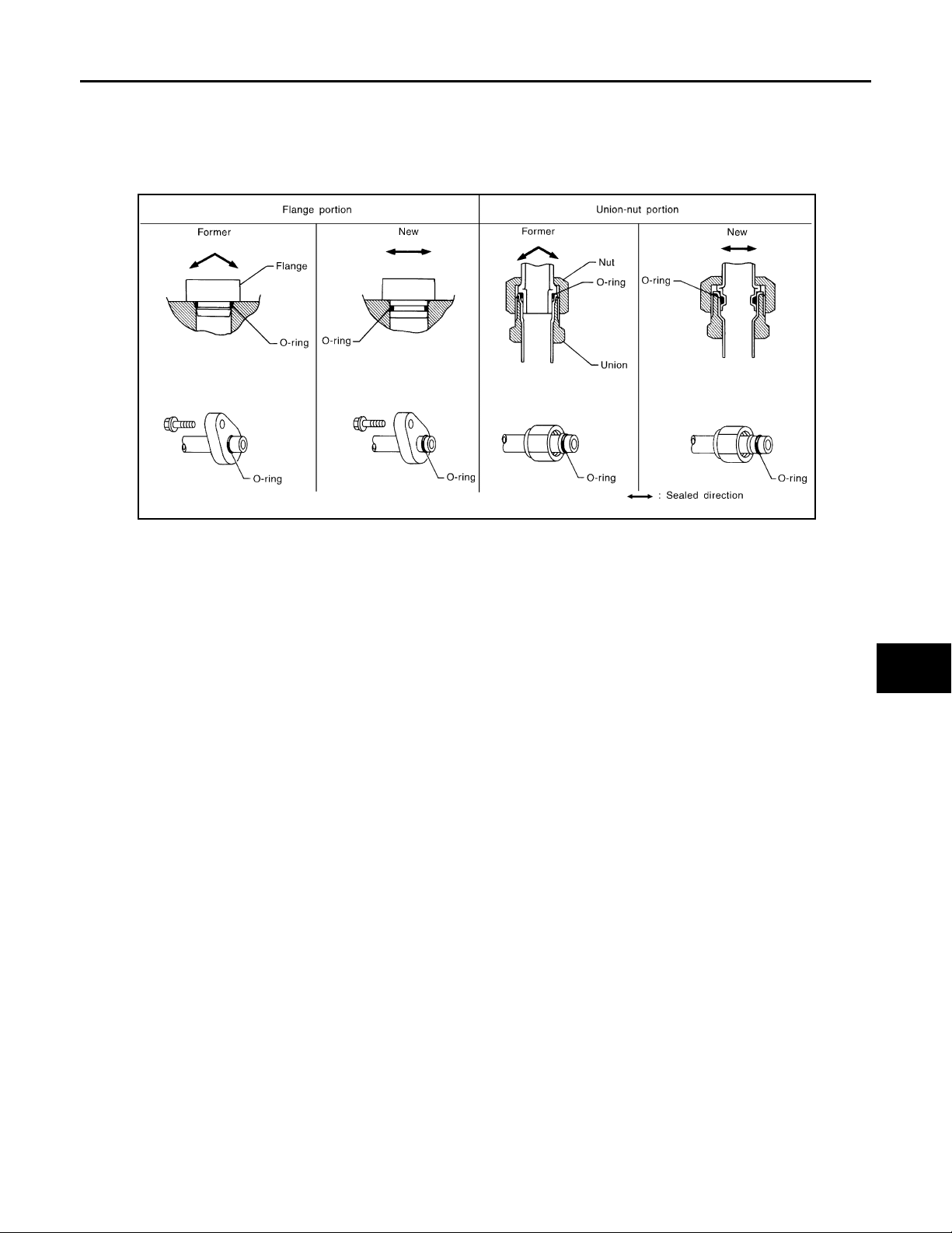
Precaution for Refrigerant Connection INFOID:0000000004277533
A new type refrigerant connection has been introduced to all refrigerant lines except the following locations.
• Expansion valve to cooling unit
• Evaporator pipes to evaporator (inside cooling unit)
• Refrigerant pressure sensor
FEATURES OF NEW TYPE REFRIGERANT CONNECTION
MTC-4
Page 5
PRECAUTIONS
Revision: October 2008
2009 Quest
< SERVICE INFORMATION >
• The O-ring has been relocated. It has also been provided with a groove for proper installation. This reduces
the possibility of the O-ring being caught in, or damaged by, the mating part. The sealing direction of the Oring is now set vertically in relation to the contacting surface of the mating part to improve sealing characteristics.
• The reaction force of the O-ring will not occur in the direction that causes the joint to pull out, thereby facilitating piping connections.
SHA815E
A
B
C
D
E
F
G
O-RING AND REFRIGERANT CONNECTION
H
I
MTC
K
L
M
N
O
P
MTC-5
Page 6
< SERVICE INFORMATION >
Revision: October 2008
2009 Quest
PRECAUTIONS
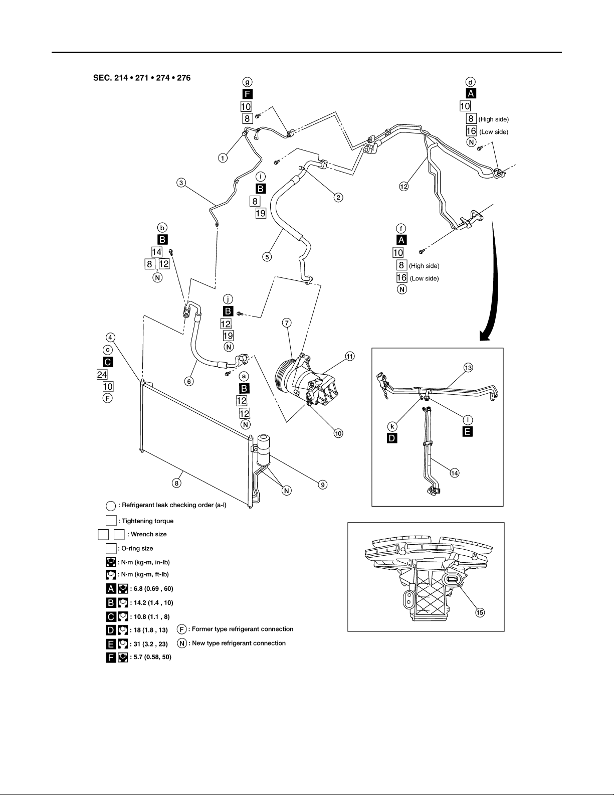
Front A/C Compressor and Condenser
1. High-pressure service valve 2. Low-pressure service valve 3. High-pressure pipe
4. Refrigerant pressure sensor 5. Low-pressure flexible hose 6. High-pressure flexible hose
7. Shaft seal 8. Condenser 9. Liquid tank
10. Pressure relief valve 11. Compressor 12. High/low pressure pipe (production)
13. High/low pressure pipe - upper
(service)
14 High/low pressure pipe - lower
(service)
MTC-6
WJIA1967E
15 Expansion valve (front)
Page 7
< SERVICE INFORMATION >
Revision: October 2008
2009 Quest
PRECAUTIONS
Rear A/C
A
B
C
D
E
F
G
LJIA0016E
CAUTION:
The new and former refrigerant connections use different O-ring configurations. Do not confuse Orings since they are not interchangeable. If a wrong O-ring is installed, refrigerant will leak at or
around the connection.
O-Ring Part Numbers and Specifications
Connection type
New 8 92471 N8210 6.8 (0.268) 1.85 (0.0728)
Former 10 J2476 89956 9.25 (0.3642) 1.78 (0.0701)
New
Former 92475 71L00 11.0 (0.433) 2.4 (0.094)
New
Former 92475 72L00 14.3 (0.563) 2.3 (0.091)
New
SHA814E
*: Always check with the Parts Department for the latest parts information.
Former 92477 N8200 17.12 (0.6740) 1.78 (0.0701)
New 24 92195 AH300 21.8 (0.858) 2.4 (0.094)
O-ring
size
12
16
19
Part number* D mm (in) W mm (in)
92472 N8210 10.9 (0.429) 2.43 (0.0957)
92473 N8210 13.6 (0.535) 2.43 (0.0957)
92474 N8210 16.5 (0.650) 2.43 (0.0957)
WARNING:
H
I
MTC
K
L
M
N
O
P
MTC-7
Page 8
PRECAUTIONS
Revision: October 2008
2009 Quest
< SERVICE INFORMATION >
Make sure all refrigerant is discharged into the recycling equipment and the pressure in the system is
less than atmospheric pressure. Then gradually loosen the discharge side hose fitting and remove it.
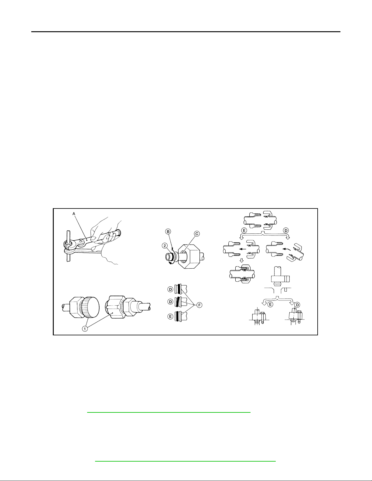
CAUTION:
When replacing or cleaning refrigerant cycle components, observe the following.
• When the compressor is removed, store it in the same position as it is when mounted on the car.
Failure to do so will cause oil to enter the low pressure chamber.
• When connecting tubes, always use a torque wrench and a back-up wrench.
• After disconnecting tubes, immediately plug all openings to prevent entry of dirt and moisture.
• When installing an air conditioner in the vehicle, connect the pipes as the final stage of the operation. Do not remove the seal caps of pipes and other components until just before required for connection.
• Allow components stored in cool areas to warm to working area temperature before removing seal
caps. This prevents condensation from forming inside A/C components.
• Thoroughly remove moisture from the refrigeration system before charging the refrigerant.
• Always replace used O-rings.
• When connecting tube, apply oil to circle of the O-rings shown in illustration. Be careful not to apply
oil to threaded portion.
• O-ring must be closely attached to dented portion of tube.
• When replacing the O-ring, be careful not to damage O-ring and tube.
• Connect tube until you hear it click, then tighten the nut or bolt by hand until snug. Make sure that
the O-ring is installed to tube correctly.
• After connecting line, conduct leak test and make sure that there is no leakage from connections.
When the gas leaking point is found, disconnect that line and replace the O-ring. Then tighten connections of seal seat to the specified torque.
1. Plug 2. O-ring A. Torque wrench
B. Apply oil C. Do not apply oil to threads D. NG (no good)
E. OK (okay) F. Inflated portion
Precaution for Service of Compressor INFOID:0000000004277534
• Plug all openings to prevent moisture and foreign matter from entering.
• When the compressor is removed, store it in the same position as it is when mounted on the car.
• When replacing or repairing compressor, follow “Maintenance of Oil Quantity in Compressor”
exactly. Refer to MTC-19, "Maintenance of Oil Quantity in Compressor"
• Keep friction surfaces between clutch and pulley clean. If the surface is contaminated with oil, wipe
it off by using a clean waste cloth moistened with thinner.
• After compressor service operation, turn the compressor shaft by hand more than 5 turns in both
directions. This will equally distribute oil inside the compressor. After the compressor is installed,
let the engine idle and operate the compressor for 1 hour.
• After replacing the compressor magnet clutch, apply voltage to the new one and check for normal
operation. Refer to ATC-164, "Removal and Installation for Compressor Clutch"
WJIA1774E
.
.
MTC-8
Page 9
PRECAUTIONS
Revision: October 2008
2009 Quest
< SERVICE INFORMATION >
Precaution for Service Equipment INFOID:0000000004277535
RECOVERY/RECYCLING EQUIPMENT
Follow the manufacturer's instructions for machine operation and machine maintenance. Never introduce any
refrigerant other than that specified into the machine.
ELECTRONIC LEAK DETECTOR
Follow the manufacturer's instructions for tester operation and tester maintenance.
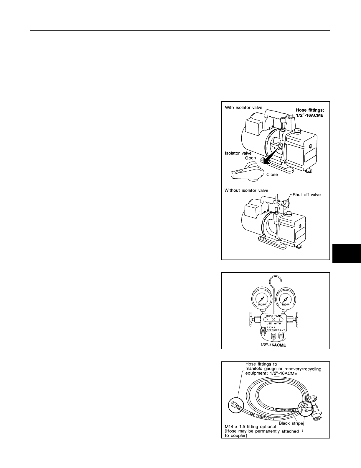
VACUUM PUMP
The oil contained inside the vacuum pump is not compatible with the
specified oil for HFC-134a (R-134a) A/C systems. The vent side of
the vacuum pump is exposed to atmospheric pressure so the vacuum pump oil may migrate out of the pump into the service hose.
This is possible when the pump is switched off after evacuation (vacuuming) and hose is connected to it.
To prevent this migration, use a manual valve situated near the
hose-to-pump connection, as follows.
• Usually vacuum pumps have a manual isolator valve as part of the
pump. Close this valve to isolate the service hose from the pump.
• For pumps without an isolator, use a hose equipped with a manual
shut-off valve near the pump end. Close the valve to isolate the
hose from the pump.
• If the hose has an automatic shut off valve, disconnect the hose
from the pump: as long as the hose is connected, the valve is open
and lubricating oil may migrate.
Some one-way valves open when vacuum is applied and close
under a no vacuum condition. Such valves may restrict the pump's
ability to pull a deep vacuum and are not recommended.
A
B
C
D
E
F
G
H
I
MANIFOLD GAUGE SET
Be certain that the gauge face indicates HFC-134a (R-134a) Make
sure the gauge set has 1/2″-16 ACME threaded connections for service hoses. Confirm the set has been used only with refrigerant
HFC-134a (R-134a) along with specified oil.
SERVICE HOSES
Be certain that the service hoses display the markings described
(colored hose with black stripe). All hoses must include positive shutoff devices (either manual or automatic) near the end of the hoses
opposite the manifold gauge.
RHA270D
SHA533D
MTC
K
L
M
N
O
P
SERVICE COUPLERS
RHA272D
MTC-9
Page 10

PRECAUTIONS
Revision: October 2008
2009 Quest
< SERVICE INFORMATION >
Never attempt to connect HFC-134a (R-134a) service couplers to a
CFC-12 (R-12) A/C system. The HFC-134a (R-134a) couplers will
not properly connect to the CFC-12 (R-12) system. If an improper
connection is attempted, discharging and contamination may occur.
Shut-off valve rotation A/C service valve
Clockwise Open
Counterclockwise Close
REFRIGERANT WEIGHT SCALE
Verify that no refrigerant other than HFC134a (R-134a) and specified
oils have been used with the scale. If the scale controls refrigerant
flow electronically, the hose fitting must be 1/2”-16 ACME.
RHA273D
RHA274D
CHARGING CYLINDER
Using a charging cylinder is not recommended. Refrigerant may be vented into air from cylinder's top valve
when filling the cylinder with refrigerant. Also, the accuracy of the cylinder is generally less than that of an
electronic scale or of quality recycle/recharge equipment.
MTC-10
Page 11
< SERVICE INFORMATION >
Revision: October 2008
2009 Quest
PREPARATION
PREPARATION
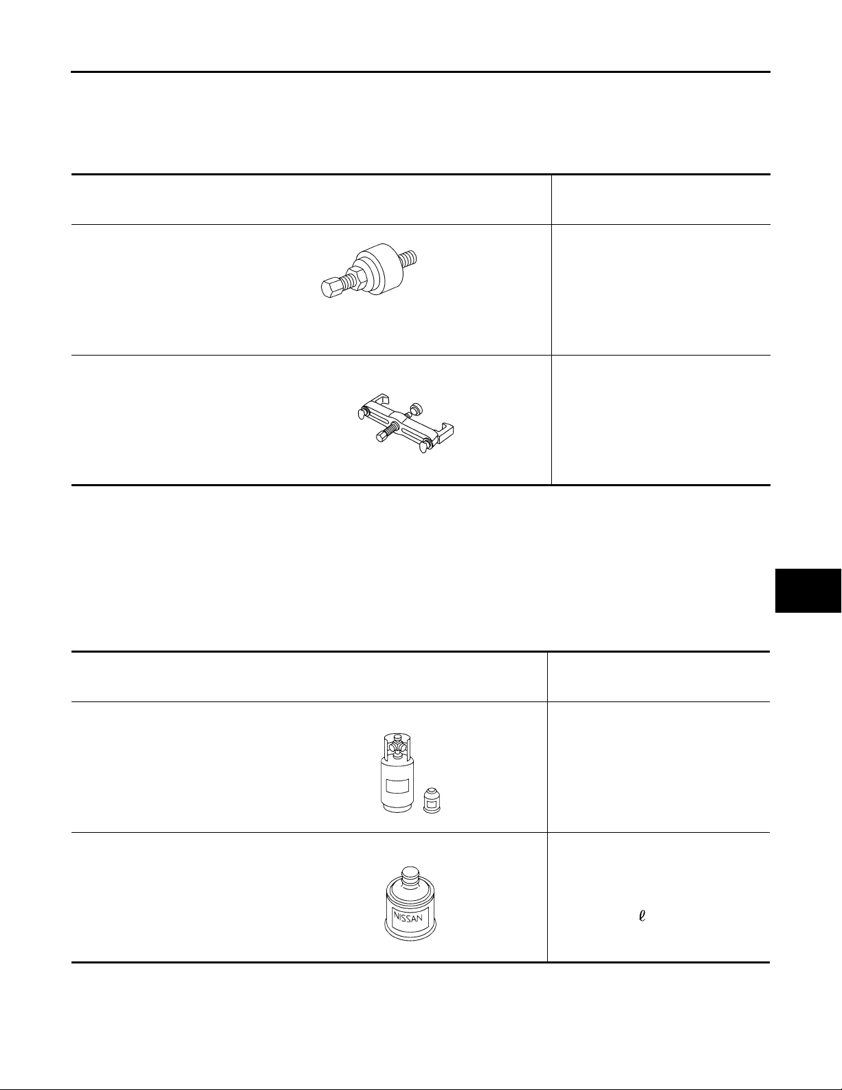
Special Service Tool INFOID:0000000004277536
The actual shapes of Kent-Moore tools may differ from those of special service tools illustrated here.
Tool number
(Kent-Moore No.)
Tool name
—
(J-38873-A)
Pulley installer
LHA171
KV99233130
(J-29884)
Pulley puller
LHA172
HFC-134a (R-134a) Service Tool and Equipment INFOID:0000000004277537
Description
Installing pulley
Removing pulley
A
B
C
D
E
F
G
H
Never mix HFC-134a refrigerant and/or its specified oil with CFC-12 (R-12) refrigerant and/or its oil.
Separate and non-interchangeable service equipment must be used for handling each type of refrigerant/oil.
Refrigerant container fittings, service hose fittings and service equipment fittings (equipment which handles
refrigerant and/or oil) are different between CFC-12 (R-12) and HFC-134a (R-134a). This is to avoid mixed
use of the refrigerants/oil.
Adapters that convert one size fitting to another must never be used refrigerant/oil contamination will occur
and compressor failure will result.
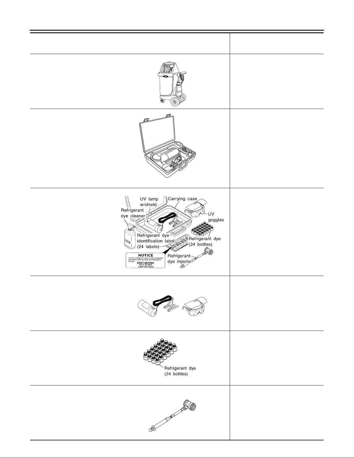
Tool number
(Kent-Moore No.)
Tool name
HFC-134a (R-134a)
(—)
Refrigerant
S-NT196
—
(—)
NISSAN A/C System Oil Type S
S-NT197
Description
Container color: Light blue
Container marking: HFC-134a (R134a)
Fitting size: Thread size
• large container 1/2”-16 ACME
Type: Poly alkylene glycol oil (PAG),
type S
Application: HFC-134a (R-134a)
swash plate compressors (NISSAN
only)
Lubricity: 40 m (1.4 US fl oz, 1.4 Imp
fl oz)
I
MTC
K
L
M
N
O
P
MTC-11
Page 12
< SERVICE INFORMATION >
Revision: October 2008
2009 Quest
PREPARATION
Tool number
(Kent-Moore No.)
Tool name
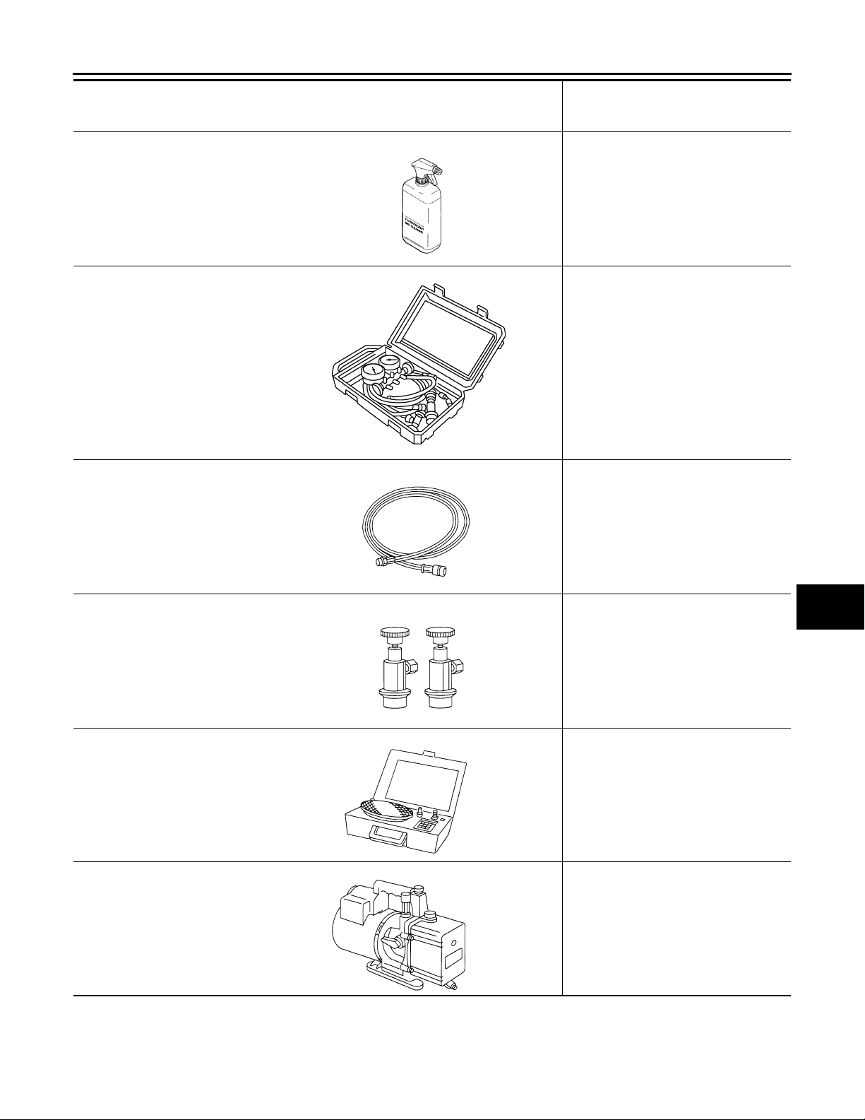
KV991J0130
(ACR2005-NI)
ACR5 A/C Service Center
—
(J-41995)
Electronic refrigerant leak detector
—
(J-43926)
Refrigerant dye leak detection kit
Kit includes:
(J-42220)
UV lamp and UV safety goggles
(J-41459)
Refrigerant dye injector
(J-41447)
Quantity 24, 1/4 ounce bottles of
HFC-134a (R-134a) fluorescent
leak detection dye
(J-43872)
Refrigerant dye cleaner
—
(J-42220)
Fluorescent dye leak detector
Description
Refrigerant recovery, recycling and recharging
WJIA0293E
Checking for refrigerant leaks
(Power supply: DC 12V battery terminal)
AHA281A
Leak detection dye
(Power supply: DC 12V battery terminal)
ZHA200H
Checking for refrigerant leak s when fluorescent dye is installed in A/C system.
Includes: UV lamp and UV safety goggles
(Power supply: DC 12V battery terminal)
—
(J-41447)
HFC-134a (R-134a) fluorescent
leak detection dye
(Box of 24, 1/4 ounce bottles)
—
(J-41459)
HFC-134a (R-134a) Dye injector
Use with (J-41447) 1/4 ounce bottles
SHA438F
Application: For HFC-134a (R-134a)
PAG oil
Container: 1/4 ounce (7.4cc) bottle
(Includes self-adhesive dye identification labels for affixing to vehicle after
charging system with dye.)
SHA439F
For injecting 1/4 ounce of fluorescent
leak detection dye into A/C system.
SHA440F
MTC-12
Page 13
< SERVICE INFORMATION >
Revision: October 2008
2009 Quest
PREPARATION
Tool number
(Kent-Moore No.)
Tool name
—
(J-43872)
Refrigerant dye cleaner
—
(J-39183-C)
Manifold gauge set (with hoses
and couplers)
Service hoses:
• (J-39500-72B)
High side hose
• (J-39500-72R)
Low side hose
• (J-39500-72Y)
Utility hose
Service couplers:
• (J-39500-20A)
High side coupler
• (J-39500-24A)
Low side coupler
SHA441F
S-NT201
RJIA0196E
Description
For cleaning dye spills.
Identification:
• The gauge face indicates R-134a.
Fitting size: Thread size
• 1/2”-16 ACME
Hose colors:
• Low side hose: Blue with black stripe
• High side hose: Red with black stripe
• Utility hose: Yellow with black stripe
or green with black stripe
Hose fitting to gauge:
• 1/2”-16 ACME
Hose fitting to service hose:
• M14 x 1.5 fitting is optional or permanently attached.
A
B
C
D
E
F
G
H
I
MTC
K
—
(J-39699)
Refrigerant weight scale
—
(J-39649)
Vacuum pum p
(Including the isolator valve)
Commercial Service Tool INFOID:0000000004277538
MTC-13
S-NT202
S-NT200
S-NT203
For measuring of refrigerant
Fitting size - thread size:
• 1/2” - 16 ACME
Capacity:
• Air displacement: 4 CFM
• Micron rating: 20 microns
• Oil capacity: 482 g (17 oz)
Fitting size: Thread size
• 1/2”-16 ACME
L
M
N
O
P
Page 14
< SERVICE INFORMATION >
Revision: October 2008
2009 Quest
PREPARATION
Tool number
Tool name
(J-41810-NI)
Refrigerant identifier equipment (R134a)
RJIA0197E
Power tool Loosening bolts and nuts
PIIB1407E
Description
For checking refrigerant purity and
system contamination
MTC-14
Page 15

< SERVICE INFORMATION >
Revision: October 2008
2009 Quest
REFRIGERATION SYSTEM
REFRIGERATION SYSTEM
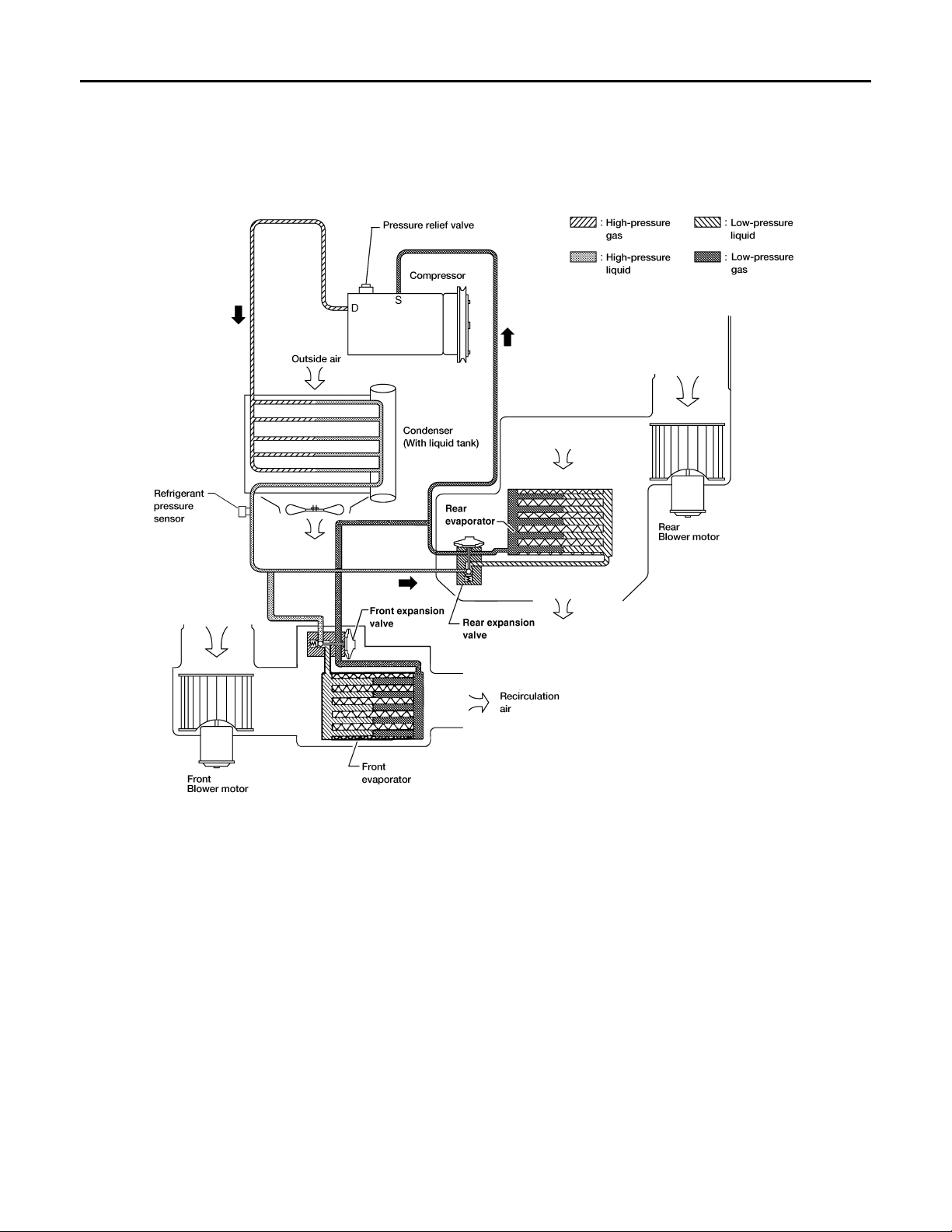
Refrigerant Cycle INFOID:0000000004277539
Refrigerant flow
The refrigerant flows in the standard pattern, that is, through the compressor, the condenser with liquid tank,
through the front and rear evaporators, and back to the compressor. The refrigerant evaporation through the
evaporator coils are controlled by a front and rear externally equalized expansion valves, located inside the
front and rear evaporator cases.
Refrigerant System Protection INFOID:0000000004277540
Refrigerant pressure sensor
The refrigerant system is protected against excessively high or low pressures by the refrigerant pressure sensor, located on the condenser. If the system pressure rises above or falls below the specifications, the refrigerant pressure sensor detects the pressure inside the refrigerant line and sends a voltage signal to the ECM.
The ECM de-energizes the A/C relay to disengage the magnetic compressor clutch when pressure on the high
2
pressure side detected by refrigerant pressure sensor is over about 2,746 kPa (28 kg/cm
about 120 kPa (1.22 kg/cm
2
, 17.4 psi).
Pressure Relief Valve
The refrigerant system is also protected by a pressure relief valve, located in the rear head of the compressor .
When the pressure of refrigerant in the system increases to an abnormal level [more than 2,990 kPa (30.5 kg/
, 398 psi), or below
A
B
C
D
E
F
G
H
I
MTC
K
L
M
N
O
P
MTC-15
Page 16
REFRIGERATION SYSTEM
Revision: October 2008
2009 Quest
< SERVICE INFORMATION >
cm2, 433.6 psi)], the release port on the pressure relief valve automatically opens and releases refrigerant into
the atmosphere.
Component Part Location INFOID:0000000004277541
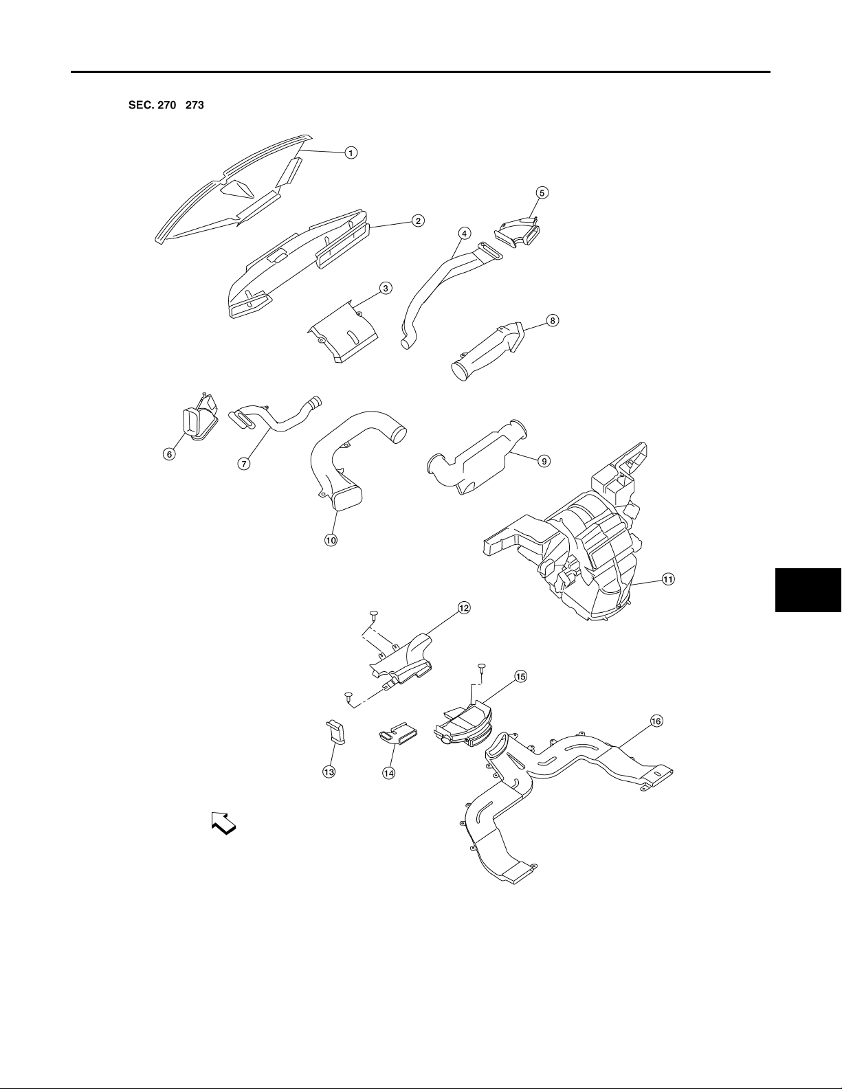
FRONT REFRIGERATION SYSTEM
WJIA1342E
MTC-16
Page 17
< SERVICE INFORMATION >
Revision: October 2008
2009 Quest
REFRIGERATION SYSTEM
A
B
C
D
E
F
G
H
I
MTC
K
L
M
N
O
1. Defroster nozzle (part of the
4. RH side demister duct 5. RH side demister duct extension 6. LH side demister duct extension
7. LH side demister duct 8. RH ventilator duct 9. Center ventilator duct
10. LH ventilator duct 11. Front heater and cooling unit assembly 12. Floor connector duct
13. Floor junction duct extension 1 4. Floor junction duct 15. Floor distribution duct
16. Floor duct ⇐ Front
instrument panel)
2. Fresh air duct 3. Defroster duct
MTC-17
WJIA2219E
P
Page 18
REFRIGERATION SYSTEM
Revision: October 2008
2009 Quest
< SERVICE INFORMATION >
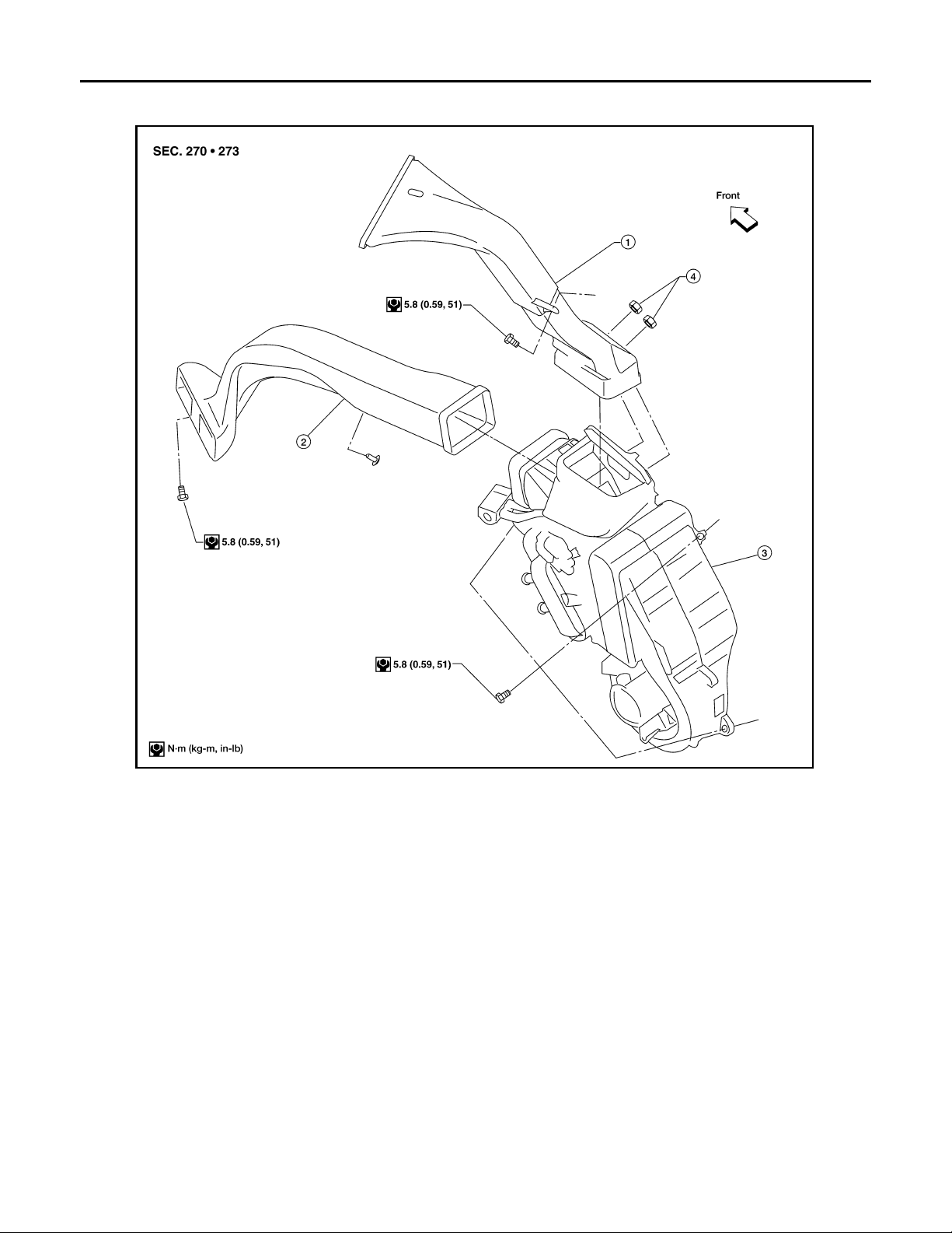
REAR REFRIGERATION SYSTEM
1 Rear overhead duct 2 Rear heat duct 3 Rear heater and cooling unit assembly
4. Clips
LJIA0086E
MTC-18
Page 19

< SERVICE INFORMATION >
Revision: October 2008
2009 Quest
OIL
OIL
Maintenance of Oil Quantity in Compressor INFOID:0000000004277542
The oil in the compressor circulates through the system with the refrigerant. Add oil to compressor when
replacing any component or after a large refrigerant leakage has occurred. It is important to maintain the specified amount.
If oil quantity is not maintained properly, the following malfunctions may result:
• Lack of oil: May lead to a seized compressor
• Excessive oil: Inadequate cooling (thermal exchange interference)
Oil
Name: NISSAN A/C System Oil Type S or equivalent
CHECKING AND ADJUSTING
CAUTION:
If excessive oil leakage is noted, do not perform the oil return operation.
Start the engine and set the following conditions:
• Engine speed: Idling to 1,200 rpm
• A/C switch: On
• Blower fan speed: Maximum position
• Temperature control: Optional [set so that intake air temperature is 25° to 30° C (77° to 86°F).]
• Intake position: Recirculation ( )
• Perform oil return operation for about ten minutes
Adjust the oil quantity according to the following table.
Oil Adjusting Procedure for Components Replacement Except Compressor
After replacing any of the following major components, add the correct amount of oil to the system.
Amount of Oil to be Added
Oil to be added to system
Part replaced
Front evaporator 75 (2.5, 2.6) —
Rear evaporator 75 (2.5, 2.6) —
Condenser 75 (2.5, 2.6) —
Liquid tank 5 (0.2, 0.2) Add if compressor is not replaced.
In case of refrigerant leak
*1: If refrigerant leak is small, no addition of oil is needed.
Amount of oil
m (US fl oz, Imp fl oz)
30 (1.0, 1.1) Large leak
— Small leak *1
Remarks
A
B
C
D
E
F
G
H
I
MTC
K
L
Oil Adjustment Procedure for Compressor Replacement
M
N
O
P
MTC-19
Page 20
< SERVICE INFORMATION >
Revision: October 2008
2009 Quest
OIL
WJIA1716E
1. New compressor 2. Old compressor 3. Recovery/recycling equipment
4. Measuring cup X 5. Measuring cup Y 6. New oil
A. Drain oil from the new compressor
into clean container
D. Install new oil equal to recorded
amounts in measuring cup s X plus Y
B. Record amount of oil recovered C.
Add an additional 5 m (0.2 US fl oz,
0.2 Imp fl oz) of new oil when replacing
liquid tank
1. Before connecting recovery/recycling equipment to vehicle, check recovery/recycling equipment gauges.
No refrigerant pressure should be displayed. If NG, recover refrigerant from equipment lines.
2. Connect recovery/recycling equipment to vehicle. Confirm refrigerant purity in supply tank using recovery/
recycling equipment and refrigerant identifier. If NG, refer to MTC-3, "Contaminated Refrigerant"
.
3. Confirm refrigerant purity in vehicle A/C system using recovery/recycling equipment and refrigerant identifier. If NG, refer to MTC-3, "Contaminated Refrigerant"
.
4. Discharge refrigerant into the refrigerant recovery/recycling equipment. Measure oil discharged into the
recovery/recycling equipment.
5. Drain the oil from the “old” (removed) compressor into a graduated container and recover the amount of
oil drained.
6. Drain the oil from the “new” compressor into a separate, clean container.
7. Measure an amount of new oil installed equal to amount drained from “old” compressor. Add this oil to
“new” compressor through the suction port opening.
8. Measure an amount of new oil equal to the amount recovered during discharging. Add this oil to “new”
compressor through the suction port opening.
9. If the liquid tank also needs to be replaced, add an additional 5 m (0.2 US fl oz, 0.2 Imp fl oz) of oil at this
time.
CAUTION:
Do not add this 5 m (0.2 US fl oz, 0.2 Imp fl oz) of oil if only replacing the compressor.
MTC-20
Page 21

< SERVICE INFORMATION >
Revision: October 2008
2009 Quest
AIR CONDITIONER CONTROL
AIR CONDITIONER CONTROL
Description INFOID:0000000004277543
The front air control provides regulation of the vehicle's interior temperature. The system is based on the position of the front air controls temperature switch selected by the driver. This is done by utilizing a microcomputer, also referred to as the front air control, which receives input signals from the following three sensors:
• Ambient sensor
• Intake sensor
• PBR (position balanced resistor).
The front air control uses these signals (including the set position of the temperature switch) to control:
• Outlet air volume
• Air temperature
• Air distribution
The front air control also provides separate regulation of the vehicle's interior temperature for the rear passenger area. The system is based on the temperature and rear blower settings selected from rear air control
(front) control dials located in the overhead console, or from the rear temperature and blower settings from the
rear air control (rear) control dials, when the REAR CTRL switch is pressed (indicator light is on) on the rear
air control (front).
The front air control is used to select:
• Outlet air volume
• Air temperature/distribution
Operation INFOID:0000000004277544
AIR MIX DOOR CONTROL
The air mix door is controlled so that in-vehicle temperature changed based on the position of the temperature
switch.
BLOWER SPEED CONTROL
Blower speed is controlled based on front and rear blower control dial settings.
When blower switch is turned, the blower motor starts and increases air flow volume each time the blower control dial is turned clockwise, and decreases air flow volume each time the blower control dial switch is turned
counterclockwise.
A
B
C
D
E
F
G
H
I
MTC
INTAKE DOORS CONTROL
The intake doors are controlled by the recirculation switch setting, and the mode (recirculation is not allowed in
floor, floor/defrost or defrost modes) switch setting.
MODE DOOR CONTROL
The mode door is controlled by the position of the mode switch.
DEFROSTER DOOR CONTROL
The defroster door is controlled by pressing the defroster mode switch.
K
L
M
N
O
P
MTC-21
Page 22
AIR CONDITIONER CONTROL
Revision: October 2008
2009 Quest
< SERVICE INFORMATION >
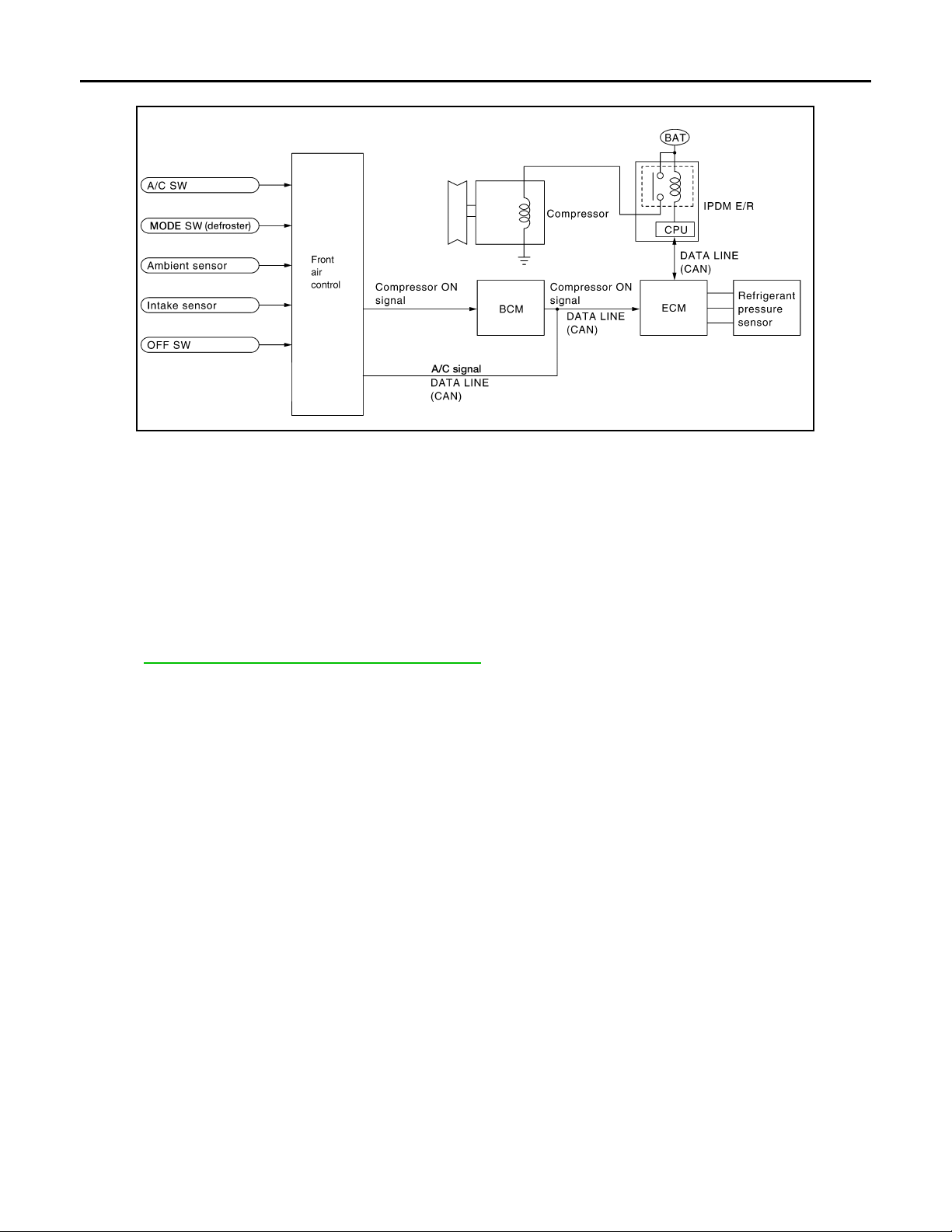
MAGNET CLUTCH CONTROL
WJIA2161E
When the A/C switch is pressed, or the defroster mode switch is pressed, the front air control outputs a compressor ON signal to BCM.
The BCM then sends a compressor ON signal to ECM and front air control, via CAN communication line.
ECM judges whether compressor can be turned ON, based on each sensor status (refrigerant pressure sensor signal, throttle angle sensor, etc.). If it judges compressor can be turned ON, it sends compressor ON signal to IPDM E/R, via CAN communication line.
Upon receipt of compressor ON signal from ECM, IPDM E/R turns air conditioner relay ON to operate compressor.
SELF-DIAGNOSTIC SYSTEM
The self-diagnostic system is built into the front air control to quickly locate the cause of certain symptoms.
Refer to ATC-45, "A/C System Self-Diagnosis Function"
.
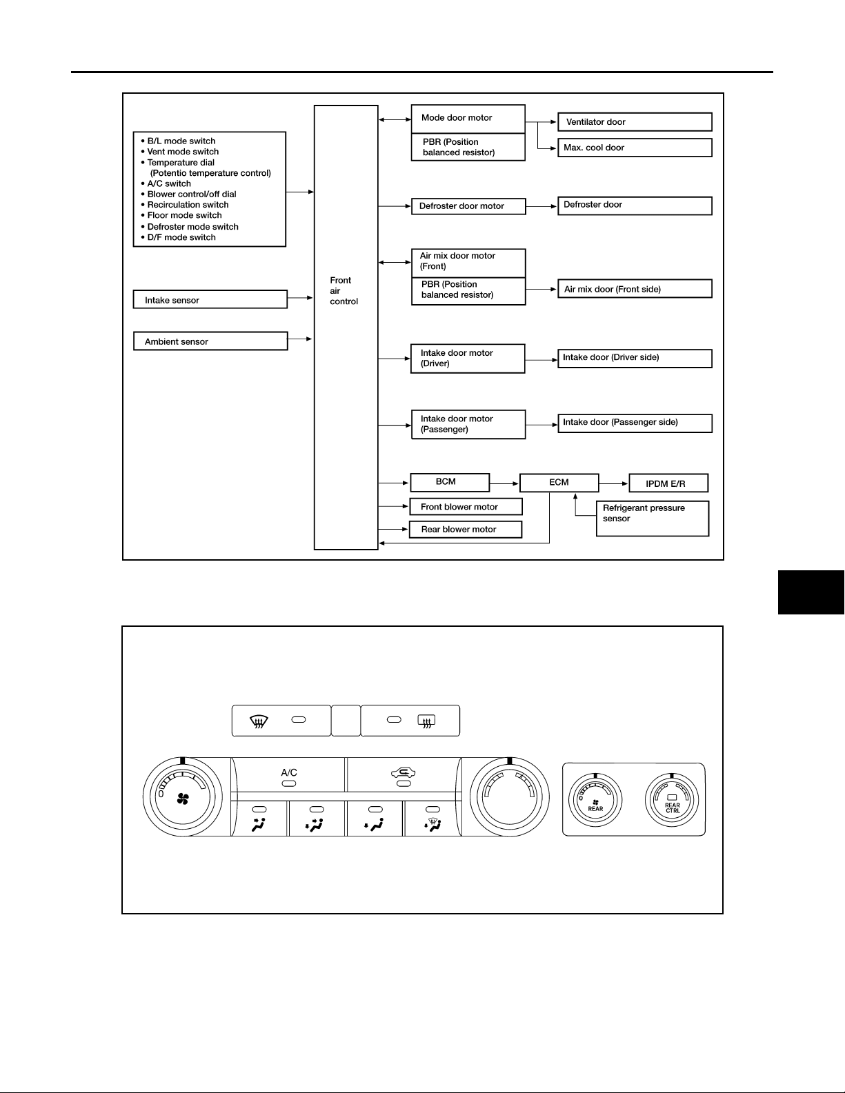
Description of Control System INFOID:0000000004277545
The control system consists of input sensors, switches, the front air control (microcomputer) and outputs.
MTC-22
Page 23
AIR CONDITIONER CONTROL
Revision: October 2008
2009 Quest
< SERVICE INFORMATION >
The relationship of these components is shown in the figure below:
A
B
C
D
E
F
G
WJIA2160E
Control Operation INFOID:0000000004277546
Front air control
H
I
MTC
K
L
M
N
O
WJIA2162E
P
MTC-23
Page 24
AIR CONDITIONER CONTROL
Revision: October 2008
2009 Quest
< SERVICE INFORMATION >
Rear air control (rear)
TEMPERATURE CONTROL DIAL (FRONT)
Increases or decreases the set temperature.
TEMPERATURE CONTROL DIAL (REAR)
Increases or decreases the set temperature.
WJIA2015E
RECIRCULATION ( ) SWITCH
• When REC switch is ON, REC switch indicator turns ON, and air inlet is set to REC.
• When REC switch is turned OFF, or when compressor is turned from ON to OFF, REC switch is automati-
cally turned OFF. REC mode can be re-entered by pressing REC switch again.
• REC switch is not operated when DEF switch is turned ON, at the D/F position, or in floor mode.
REAR WINDOW DEFOGGER SWITCH
When switch is ON, rear window is defogged.
OFF SWITCH
The compressor and blower are OFF, the intake doors are set to the outside air position, and the air outlet
doors are set to the foot position.
A/C SWITCH
The compressor is ON or OFF.
MODE SWITCHS (FRONT)
Controls the air discharge outlets through control of the mode and defroster doors.
MODE DIAL (REAR)
Controls the air/temperature at discharge outlets.
FRONT BLOWER CONTROL DIAL
Manually control the blower speed. Fourteen speeds are available for manual control.
REAR BLOWER CONTROL DIAL (FRONT)
When the REAR CTRL switch is off (indicator off) the rear air control (front) controls the rear blower motor
speed regardless of the rear air control (rear) blower control dial (rear) position. The rear air control (front) controls the blower motor speed and the temperature/mode settings.
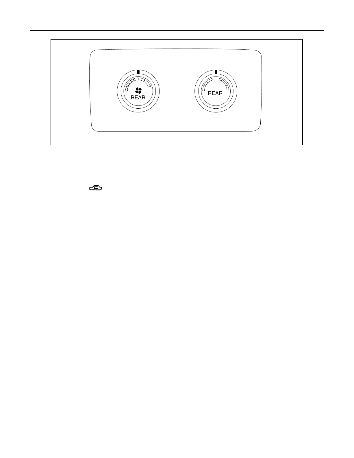
REAR BLOWER CONTROL DIAL (REAR)
When the REAR CTRL switch is on (indicator on) the rear air control (rear) controls the rear blower motor
speed regardless of the rear air control (front) blower control dial (front) position. The rear air control (rear)
controls the blower motor speed and the temperature/mode settings.
MTC-24
Page 25
AIR CONDITIONER CONTROL
Revision: October 2008
2009 Quest
< SERVICE INFORMATION >
Discharge Air Flow INFOID:0000000004277547
FRONT
WJIA2016E
A
B
C
D
REAR
NOTE:
Hot air comes from the floor vents, cold air comes from the roof
vents, and blended air comes from both vents.
E
F
G
H
I
MTC
K
L
LJIA0127E
M
N
O
P
MTC-25
Page 26
< SERVICE INFORMATION >
Revision: October 2008
2009 Quest
AIR CONDITIONER CONTROL
System Description
SWITCHES AND THEIR CONTROL FUNCTION
INFOID:0000000004277548
WJIA0531E
CAN Communication System Description INFOID:0000000004277549
Refer to LAN-3, "CAN Communication System".
WJIA2163E
MTC-26
Page 27
< SERVICE INFORMATION >
Revision: October 2008
2009 Quest
TROUBLE DIAGNOSIS
TROUBLE DIAGNOSIS
CONSULT-III Function (HVAC) INFOID:0000000004277550
CONSULT-III can display each diagnostic item using the diagnostic test modes shown following.
Diagnostic mode Description
SELF-DIAG RESULTS Displays front air control self-diagnosis results.
DATA MONITOR Displays front air control input/output data in real time.
CAN DIAG SUPPORT MNTR The result of transmit/receive diagnosis of CAN communication can be read.
ECU PART NUMBER Front air control part number can be read.
SELF-DIAGNOSIS
Operation Procedure
1. Touch “SELF-DIAG RESULTS” on “SELECT DIAG MODE” screen to view all set DTC's.
Display Item List
DTC Reference page
B2573 Battery voltage out of range SC-4
B2575 BCM not responding to A/C request MTC-90, "Magnet Clutch Circuit"
B2576 BCM not responding to rear defroster request GW-76
B2577 Air mix door motor (front) circuit failure MTC-54, "Air Mix Door Motor Circuit"
B257A Air mix door motor (rear) circuit failure MTC-54, "Air Mix Door Motor Circuit"
B257B Ambient sensor circuit open
B257C Ambient sensor circuit short
B2581 Intake sensor circuit short
B2582 Intake sensor circuit open
B2583 Defroster door motor circuit failure MTC-67, "Defroster Door Motor Circuit"
B2584 Intake door motor (passenger) circuit failure MTC-63, "Intake Door Motor Circuit"
U1000 CAN bus fault LAN-6
B2586 Intake door motor (driver) circuit failure MTC-63, "Intake Door Motor Circuit"
B2587 Stuck button MTC-113, "Removal and Installation"
B2587 Mode door motor circuit failure MTC-50, "Mode Door Motor Circuit"
DATA MONITOR
MTC-108, "Ambient Sensor Circuit"
MTC-110, "Intake Sensor Circuit"
A
B
C
D
E
F
G
H
I
MTC
K
L
M
Operation Procedure
1. Touch “DATA MONITOR” on “SELECT DIAG MODE” screen.
2. Touch either “MAIN SIGNALS” or “SELECTION FROM MENU” on “DATA MONITOR” screen.
MAIN SIGNALS Monitors all the items.
SELECTION FROM
MENU
3. When “SELECTION FROM MENU” is selected, touch items to be monitored. When “MAIN SIGNALS” is
selected, all the items will be monitored.
4. Touch “START”.
5. Touch “RECORD” while monitoring, then the status of the monitored item can be recorded. To stop
recording, touch “STOP”.
Display Item List
Selects and monitors the individual item selected.
MTC-27
N
O
P
Page 28

TROUBLE DIAGNOSIS
Revision: October 2008
2009 Quest
< SERVICE INFORMATION >
Monitor item Val ue Contents
BATT VIA CAN "V" Displays battery voltage signal.
IGN VIA CAN "ON/OFF" Displays ignition switch signal.
AMB TEMP SEN "°C/°F" Displays ambient temperature sensor signal.
EVAP TEMP SEN "°C/°F" Displays intake sensor signal.
RR TEMPSET FR "V" Displays air mix door (front) set point signal.
RR TEMPSET RR "V" Displays air mix door (rear) set point signal.
MODE FDBCK "V" Displays mode door motor feedback signal.
DVR MIX FDBCK "V" Displays intake door motor (driver) feedback signal.
PAS MIX FDBCK "V" Displays intake door motor (passenger) feedback signal.
RR FDBCK "V" Displays air mix door motor (rear) feedback signal.
DEF FDBCK "V" Displays defroster door motor feedback signal.
RECIRC "ON/OFF" Displays recirculation switch signal.
A/C "ON/OFF" Displays A/C switch signal.
MODE "ON/OFF" Displays MODE dial signal.
RR DEFOG "ON/OFF" Displays rear defroster request signal.
" [ PNL ]"
" [ MIX ]"
MODE SELECT
" [ FLR ]"
" [ DEFR ]"
" [ MAX ]"
" [ DENT ]"*
*: DENT is displayed when MODE dial is between selections.
Displays mode door motor position.
CONSULT-III Function (BCM) INFOID:0000000004277551
CONSULT- III can display each diagnostic item using the diagnostic test modes shown following.
BCM diagnostic
test item
Inspection by part
DATA MONITOR
Operation Procedure
1. Touch “AIR CONDITIONER” on “SELECT TEST ITEM” screen.
2. Touch “DATA MONITOR” on “SELECT DIAG MODE” screen.
3. Touch either “ALL SIGNALS” or “SELECTION FROM MENU” on “DATA MONITOR” screen.
Diagnostic mode Description
Supports inspections and adjustments. Commands are transmitted to the BCM for
WORK SUPPORT
DATA MONITOR Displays BCM input/output data in real time.
ACTIVE TEST Operation of electrical loads can be checked by sending drive signal to them.
SELF-DIAG RESULTS Displays BCM self-diagnosis results.
CAN DIAG SUPPORT MNTR The result of transmit/receive diagnosis of CAN communication can be read.
ECU PART NUMBER BCM part numb er can be read.
CONFIGURATION Performs BCM configuration read/write functions.
setting the status suitable for required operation, input/output signals are received
from the BCM and received data is displayed.
ALL SIGNALS Monitors all the items.
SELECTION FROM
MENU
4. Touch “START”.
Selects and monitors the individual item selecte d.
MTC-28
Page 29
TROUBLE DIAGNOSIS
Revision: October 2008
2009 Quest
< SERVICE INFORMATION >
5. When “SELECTION FROM MENU” is selected, touch items to be monitored. When “ALL SIGNALS” is
selected, all the items will be monitored.
6. Touch “RECORD” while monitoring, then the status of the monitored item can be recorded. To stop
recording, touch “STOP”.
Display Item List
A
B
Monitor item name “operation or
unit”
IGN ON SW “ON/OFF” Displays “IGN Position (ON)/OFF, ACC Position (OFF)” status as j udg ed f rom ign iti on s wi tch sign al .
COMP ON SIG “ON/OFF” Displays “COMP (ON)/COMP (OFF)” status as judged from air conditioner switch signal.
FAN ON SIG “ON/OFF” Displays “FAN (ON)/FAN (OFF)” status as judged from blower motor switch signal.
Contents
How to Perform Trouble Diagnosis for Quick and Accurate Repair INFOID:0000000004277552
WORK FLOW
SHA900E
*1 MTC-45, "Operational Check (Front)"
SYMPTOM TABLE
Symptom Reference Page
MTC-48, "Power
A/C system does not come on. Go to Trouble Diag nosis Procedure for A/C System.
A/C system cannot be controlled. Go to Self-diagnosis Function.
Air outlet does not change.
Mode door motor is malfunctioning.
Discharge air temperature does not change.
Air mix door motor is malfunctioning.
Intake door does not change.
Intake door motor is malfunctioning.
Defroster door motor is malfunctioning. Go to Trouble Diagnosis Procedure for Defroster Door Motor.
Front blower motor operation is malfunctioning.
Rear blower motor operation is malf unctioning.
Go to Trouble Diagnosis Procedure for Mode Door Motor.
Go to Trouble Diagnosis Procedure for Air Mix Door Motor.
Go to Trouble Diagnosis Procedure for Intake Door Motor.
Go to Trouble Diagnosis Procedure for Front Blower Motor.
Go to Trouble Diagnosis Procedure for Rear Blower Motor.
Supply and
Ground Circuit for
Front Air Control"
MTC-44, "A/C
System Self-Diag-
nosis Function"
MTC-50, "Mode
Door Motor Cir-
cuit"
MTC-54, "Air Mix
Door Motor Cir-
cuit"
MTC-63, "Intake
Door Motor Cir-
cuit"
MTC-67, "Defroster Door Motor Circuit"
MTC-69, "Front
Blower Motor Cir-
cuit"
MTC-75, "Rear
Blower Motor Circuit"
C
D
E
F
G
H
I
MTC
K
L
M
N
O
P
MTC-29
Page 30

TROUBLE DIAGNOSIS
Revision: October 2008
2009 Quest
< SERVICE INFORMATION >
Symptom Reference Page
Rear discharge air temperature and/or air
outlet does not change.
Magnet clutch does not engage. Go to Trouble Diagnosis Procedure for Magnet Clutch.
Insufficient cooling Go to Trouble Diagnosis Procedure for Insufficient Cooling.
Insufficient heating Go to Trouble Diagnosis Procedure for Insufficient Heating.
Noise Go to Trouble Diagnosis Procedure for Noise. MTC-105, "Noise"
Self-diagnosis cannot be performed. Go to Trouble Diagnosis Procedure for Self-diagnosis.
Go to Trouble Diagnosis Procedure for Rear Air Control circuit.
MTC-84, "Rear
Temperature Control Circuit"
MTC-90, "Magnet
Clutch Circuit"
MTC-94, "Insuffi-
cient Cooling"
MTC-101, "Insuffi-
cient Heating"
MTC-107, "Self-
Diagnosis"
Component Parts and Harness Connector Location
ENGINE COMPARTMENT
INFOID:0000000004277553
MTC-30
Page 31

< SERVICE INFORMATION >
Revision: October 2008
2009 Quest
TROUBLE DIAGNOSIS
A
B
C
D
E
F
G
1. Refrigerant pressure sensor E111 2. Compressor F3 (view from right tire
housing)
4. Heater pump E127
3. Ambient Sensor E1
H
I
MTC
K
L
M
N
WJIA2221E
O
FRONT PASS ENGE R COMPARTMENT
P
MTC-31
Page 32

< SERVICE INFORMATION >
Revision: October 2008
2009 Quest
TROUBLE DIAGNOSIS
1. Intake door motor (driver) M58 2. Air mix door motor (front) M307 3. Evaporator
4. Intake sensor M305 5. Variable blower control (front) M122 6. Mode door motor M304
7. Defroster door motor M303 8. Intake door motor (passenger) M302 9. Front air control M49, M50
10. Front blower motor M62
REAR PA SS ENGE R COMPARTMENT
WJIA2164E
MTC-32
Page 33

< SERVICE INFORMATION >
Revision: October 2008
2009 Quest
TROUBLE DIAGNOSIS
A
B
C
D
E
F
G
WJIA2172E
1. Rear air control (rear) B150 2. Rear blower motor B134 3. Variable blower control (rear) B151
4. Air mix door motor (rear) B146
H
I
MTC
K
L
M
N
O
P
MTC-33
Page 34

< SERVICE INFORMATION >
Revision: October 2008
2009 Quest
TROUBLE DIAGNOSIS
Schematic
INFOID:0000000004277554
WJWA0424E
MTC-34
Page 35

TROUBLE DIAGNOSIS
Revision: October 2008
2009 Quest
< SERVICE INFORMATION >
Wiring Diagram - A/C,M - INFOID:0000000004277555
A
B
C
D
E
F
G
H
I
MTC
K
L
M
N
O
MTC-35
WJWA0425E
P
Page 36

< SERVICE INFORMATION >
Revision: October 2008
2009 Quest
TROUBLE DIAGNOSIS
WJWA0426E
MTC-36
Page 37

< SERVICE INFORMATION >
Revision: October 2008
2009 Quest
TROUBLE DIAGNOSIS
A
B
C
D
E
F
G
H
I
MTC
K
L
M
N
O
WJWA0427E
P
MTC-37
Page 38

< SERVICE INFORMATION >
Revision: October 2008
2009 Quest
TROUBLE DIAGNOSIS
WJWA0428E
MTC-38
Page 39

< SERVICE INFORMATION >
Revision: October 2008
2009 Quest
TROUBLE DIAGNOSIS
A
B
C
D
E
F
G
H
I
MTC
K
L
M
N
O
WJWA0429E
P
MTC-39
Page 40

< SERVICE INFORMATION >
Revision: October 2008
2009 Quest
TROUBLE DIAGNOSIS
WJWA0430E
MTC-40
Page 41

< SERVICE INFORMATION >
Revision: October 2008
2009 Quest
TROUBLE DIAGNOSIS
A
B
C
D
E
F
G
H
I
MTC
K
L
M
N
O
LJWA0013E
P
MTC-41
Page 42

< SERVICE INFORMATION >
Revision: October 2008
2009 Quest
TROUBLE DIAGNOSIS
WJWA0432E
MTC-42
Page 43

TROUBLE DIAGNOSIS
Revision: October 2008
2009 Quest
< SERVICE INFORMATION >
Front Air Control Terminal and Reference Value INFOID:0000000004277556
FRONT AIR CONTROL HARNESS CONNECTOR TERMINAL LAYOUT
WJIA2020E
A
B
C
D
TERMINALS AND REFERENCE VALUES FOR FRONT AIR CONTROL
Terminal
No.
3Y
4 L/R Compressor ON signal
5 L/Y Blower ON signal
6 Y/B Air mix door motor (front) feedback ON - 0 - 5V
7 LG Mode door motor feedback ON - 0 - 5V
10 R/L Heater pump ON
11 R/W Intake sensor ON - 0 - 5V
12 W/G Aux blower speed ON - 0 - 5V
13 O Variable blower control (front) signal ON - 0 - 5V
15 G/Y Power supply for IGN ON - Battery voltage
16 W/L Rear defroster request ON - Battery voltage
17 L/B Air mix door motor (front) CCW ON Counterclockwise rotation Battery voltage
18 L/W Air mix door motor (front) CW ON Clockwise rotation Battery voltage
19 L/O Mode door motor CCW ON Counterclockwise rotation Battery voltage
20 SB Mode door motor CW ON Clockwise rotation Battery voltage
21 R Intake door motor (driver) CW ON Counterclockwise rotation Battery voltage
22 R/B Intake door motor (driver) CCW ON Clockwise rotation Battery voltage
23 W Defroster door motor CW ON Clockwise rotation Battery voltage
24 W/B Defroster door m otor CCW ON Counterclockwise rotation Battery voltage
25 GR/R Ambient sensor ON - 0 - 5V
26 O/B Sensor return ON - 0 - 5V
27 Y/R Power supply for BAT - - Battery voltage
28 W/G
30 G/B Air mix door motor (rear) feedback ON - 0 - 5V
33 R/G AUX Rear select switch ON - 0 - 5V
34 BR/Y AUX backlight dim ON Headlamps OFF Battery voltage
35 V/W AUX tell tale LED ON T ell ta le OFF Battery voltage
Wire
Color
Item
Position balance resistor (PBR)
ground
Position balanced resistor (PBR)
power
Ignition
Switch
ON - 0V
ON A/C switch OFF 5V
ON A/C switch ON 0V
ON Fan switch OFF 5V
ON Fan switch ON 0V
Heater pump OFF Battery voltage
Heater pump ON 0V
ON - 5V
Condition
E
Voltage (V)
(Approx.)
F
G
H
I
MTC
K
L
M
N
O
P
MTC-43
Page 44

< SERVICE INFORMATION >
Revision: October 2008
2009 Quest
TROUBLE DIAGNOSIS
Terminal
No.
36 B Ground - - 0V
40 P CAN-L ON - 41 L CAN-H ON - 43 P/L Air mix door motor (rear) CW ON Clockwise rotation Battery voltage
44 LG/R Air mix door motor (rear) CCW ON Counterclockwise rotation Battery voltage
45 P Intake door motor (passenger) CW ON Clockwise rotation Battery voltage
46 P/B Intak e door motor (passenger) CCW ON Counterclockwise rotation Battery voltage
47 Y/L Rear aux blower pot ON Rear blower motor 0 - 5V
48 W/R Rear aux temp pot ON
49 G/O Front aux blower pot ON
50 GR/L Front aux temp pot ON
Wire
Color
Item
Ignition
Switch
Condition
Rear air control (rear) tem-
perature control dial
Rear air control (front)
blower motor
Rear air control (front) tem-
perature control dial
0 - 5V
0 - 5V
0 - 5V
A/C System Self-Diagnosis Function
DESCRIPTION
NOTE:
If using CONSULT-III, refer to MTC-27, "CONSULT-III Function (HVAC)"
.
Voltage (V)
(Approx.)
INFOID:0000000004277557
The self-diagnostic system diagnoses sensors, CAN system, battery voltage, and stuck button on front air
control. Refer to applicable sections (items) for details. Shifting from usual control to the self-diagnostic system
is accomplished by the following:
The ignition switch must be on and ambient temperature must be at least 10°C (50°F). Press the A/C switch to
turn on the HVAC system. Press the vent ( and defrost button at the same time. Then press the recirculation ( ) switch. the fault codes (if any are present) will display in the ambient temperature area. Refer to
MTC-44
Page 45

TROUBLE DIAGNOSIS
Revision: October 2008
2009 Quest
< SERVICE INFORMATION >
ATC-45, "A/C System Self-Diagnosis Function". The fault codes will continue to scroll until self-diagnostic
mode is exited. To exit self-diagnostic mode, press any button.
A
B
C
D
E
F
G
SELF-DIAGNOSIS CODE CHART
NOTE:
If using CONSULT-III, refer to MTC-27, "CONSULT-III Function (HVAC)"
Code No. Reference page
03 Battery voltage out of range SC-4
20 BCM not responding to A/C requ est GW-76
21 BCM not responding to rear defroster request GW-76
22 Air mix door motor (front) circuit failure MTC-54, "Air Mix Door Motor Circuit"
38 Air mix door motor (rear) circuit failure MTC-54, "Air Mix Door Motor Circuit"
40 Ambient sensor circuit short
41 Ambient sensor circuit open
56 Intake sensor circuit short
57 Intake sensor circuit open
62 Defroster door drive short /open/out of limits MTC-67, "Defroster Door Motor Circuit"
72 Intake door motor (passenger) short/open MTC-63, "Intake Door Motor Circuit"
80 CAN bus fault LAN-6
82 Intake door motor (driver) short/open MTC-63, "Intake Door Motor Circuit"
90 Stuck button MTC-113, "Removal and Installa tion"
92 Mode door motor short/open/out of limits MTC-50, "Mode Door Motor Circuit"
ATC-117, "Ambient Sensor Circuit"
ATC-124, "Intake Sensor Circuit"
.
H
WJIA2166E
I
MTC
K
L
M
N
O
P
Operational Check (Front) INFOID:0000000004277558
The purpose of the operational check is to confirm that the system operates properly.
Conditions : Engine running and at normal operating temperature
MTC-45
Page 46

TROUBLE DIAGNOSIS
Revision: October 2008
2009 Quest
< SERVICE INFORMATION >
CHECKING BLOWER
1. Turn blower control dial clockwise. Blower should operate on low speed.
2. Turn the blower control dial again, and continue checking each blower speed until all speeds are checked.
3. Leave blower on maximum speed.
If NG, Refer to MTC-69, "Front Blower Motor Circuit"
If OK, continue with next check.
CHECKING DISCHARGE AIR
1. Press each mode switch.
2. Confirm that discharge air comes out according to the air distribution table. Refer to MTC-25, "Discharge Air Flow"
Mode door position is checked in the next step.
If NG, go to trouble diagnosis procedure for MTC-50, "Mode Door
Motor Circuit".
If OK, continue with next check.
NOTE:
Confirm that the compressor clutch is engaged (sound or visual
inspection) and intake door position is at fresh when the DEF or D/F
is selected.
.
WJIA0528E
CHECKING RECIRCULATION
1. Press recirculation ( ) switch one time. Recirculation indicator should illuminate.
2. Press recirculation ( ) switch one more time. Recirculation indicator should go off.
3. Listen for intake door position change (blower sound should change slightly).
If NG, go to trouble diagnosis procedure for MTC-63, "Intake Door Motor Circuit"
If OK, continue with next check.
NOTE:
Confirm that the compressor clutch is engaged (sound or visual inspection) and intake door position is at fresh
when the DEF, D/F or floor is selected.
.
CHECKING TEMPERATURE DECREASE
1. Rotate temperature dial counterclockwise.
2. Check for cold air at appropriate discharge air outlets.
If NG, listen for sound of air mix door motor operation. If OK, go to trouble diagnosis procedure for MTC-94,
"Insufficient Cooling". If air mix door motor appears to be malfuncti oning, go to troubl e diagnosis procedure for
MTC-54, "Air Mix Door Motor Circuit"
If OK, continue with next check.
.
CHECKING TEMPERATURE INCREASE
1. Rotate temperature dial clockwise.
2. Check for hot air at appropriate discharge air outlets.
If NG, listen for sound of air mix door motor operation. If OK, go to trouble diagnosis procedure for MTC-101,
"Insufficient Heating". If air mix door motor appears to be malfunctioning, Refer to MTC-54, "Air Mix Door
Motor Circuit".
If OK, continue with next check.
CHECK A/C SWITCH
1. Press A/C switch with the blower ON.
2. A/C switch indicator will turn ON.
• Confirm that the compressor clutch engages (sound or visual inspection).
NOTE:
If current mode setting is DEF or D/F compressor clutch may already be engaged
If NG, Refer to MTC-90, "Magnet Clutch Circuit"
.
MTC-46
Page 47

TROUBLE DIAGNOSIS
Revision: October 2008
2009 Quest
< SERVICE INFORMATION >
If OK, continue with next check.
Operational Check (Rear) INFOID:0000000004277559
The purpose of the operational check is to confirm that the system operates properly.
Conditions : Engine running and at normal operating temperature
A
B
CHECKING REAR BLOWER MOTOR
1. Press the A/C switch on the front air control.
2. Rotate rear air control (front) blower control dial to low speed.
3. Rotate the blower control dial clockwise and continue checking blower speed until all speeds are checked.
4. Leave blower on maximum speed.
5. Press the REAR CTRL switch from the rear air control (front).
6. Rotate rear air control (rear) blower control dial to low speed.
7. Rotate the blower control dial clockwise and continue checking blower speed until all speeds are checked.
8. Leave blower on maximum speed.
If NG, go to trouble diagnosis procedure for ATC-84, "Rear Blower Motor Circuit"
.
If OK, continue with next check.
CHECKING REAR DISCHARGE AIR
1. Rotate the rear air control (front) temperature/mode control dial
from maximum heat to maximum cold.
2. Confirm that discharge air comes out according to the air distribution table. Refer to ATC-25, "Discharge Air Flow"
3. Press the REAR CTRL switch from the rear air control (front).
4. Rotate the rear air control (rear) temperature/mode control dial
from maximum heat to maximum cold.
5. Confirm that discharge air comes out according to the air distribution table. Refer to ATC-25, "Discharge Air Flow"
Air mix door position is checked in the next step.
If NG, go to trouble diagnosis procedure for ATC-57, "Air Mix Door
Motor Circuit".
If OK, continue with next check.
.
.
C
D
E
F
G
H
I
MTC
K
CHECKING REAR TEMPERATURE DECREASE
1. Rotate the rear air control (front) temperature/mode control dial counterclockwise to maximum cold.
2. Check for cold air at appropriate discharge air outlets.
3. Press the REAR CTRL switch from the rear air control (front).
4. Rotate the rear air control (rear) temperature/mode control dial counterclockwise to maximum cold.
5. Check for cold air at appropriate discharge air outlets.
If NG, listen for sound of air mix door motor operation. If OK, go to trouble diagnosis procedure for ATC-102,
"Insufficient Cooling". If air mix door motor appears to be malfunctioning, go to ATC-57, "Air Mix Door Motor
Circuit".
If OK, continue with next check.
MTC-47
LJIA0127E
L
M
N
O
P
Page 48

TROUBLE DIAGNOSIS
Revision: October 2008
2009 Quest
< SERVICE INFORMATION >
CHECKING REAR TEMPERATURE INCREASE
1. Rotate the rear air control (front) temperature/mode control dial clockwise to maximum heat.
2. Check for hot air at appropriate discharge air outlets.
3. Press the REAR CTRL switch from the rear air control (front).
4. Rotate the rear air control (rear) temperature/mode control dial clockwise to maximum heat.
5. Check for hot air at appropriate discharge air outlets.
If NG, listen for sound of air mix door motor operation. If OK, go to trouble diagnosis procedure for ATC-109,
"Insufficient Heating". If air mix door motor appears to be malfunctioning, go to ATC-57, "Air Mix Door Motor
Circuit".
If NG, go to trouble diagnosis procedure for ATC-93, "Rear Air Temperature Control Circuit"
If all operational checks are OK (symptom cannot be duplicated), go to ATC-30, "How to Perform Trouble
Diagnosis for Quick and Accurate Repair" and perform tests as outlined. If symptom appears, refer to ATC-30,
"How to Perform Trouble Diagnosis for Quick and Accurate Repair" and perform applicable trouble diagnosis
procedures.
.
Power Supply and Ground Circuit for Front Air Control INFOID:0000000004277560
SYMPTOM: A/C system does not come on.
INSPECTION FLOW
1.CONFIRM SYMPTOM BY PERFORMING OPERATIONAL CHECK
1. Press A/C switch.
2. Confirm that the compressor clutch engages (sound or visual inspection).
Can a symptom be duplicated?
YES >> GO TO 3.
NO >> GO TO 2.
2.PERFORM COMPLETE OPERATIONAL CHECK
Perform a complete operational check and check for any symptoms. Refer to MTC-45, "Operational Check
(Front)".
Can a symptom be duplicated
YES >> Refer toMTC-29, "How to Perform Trouble Diagnosis for Quick and Accurate Repair".
NO >> System OK.
3.CHECK FOR SERVICE BULLETINS
Check for any service bulletins.
>> GO TO 4.
4.CHECK POWER AND GROUND CIRCUIT
Check main power supply and ground circuit. Refer to "DIAGNOSTIC PROCEDURE FOR A/C SYSTEM".
OK or NG
OK >> System OK.
NO >> Replace front air control. Refer to MTC-113, "Removal and Installation"
.
COMPONENT DESCRIPTION
Front Air Control
The front air control has a built-in microcomputer which processes information sent from various sensors
needed for air conditioner operation. The air mix door motors, mode door motor, intake door motors, defroster
door motor, blower motor and compressor are then controlled.
The front air control is unitized with control mechanisms. When the various switches and temperature dials are
operated, data is input to the front air control.
Self-diagnostic functions are also built into the front air control to provide quick check of malfunctions in the air
conditioner system.
Potentio Temperature Control (PTC)
MTC-48
Page 49

TROUBLE DIAGNOSIS
Revision: October 2008
2009 Quest
< SERVICE INFORMATION >
The PTC is built into the front air control. It can be set from cold to
hot or any intermediate position by rotating the temperature dial.
DIAGNOSTIC PROCEDURE FOR A/C SYSTEM
SYMPTOM: A/C system does not come on.
A
B
C
WJIA2171E
D
E
F
G
1.CHECK POWER SUPPLY CIRCUITS FOR FRONT AIR CONTROL
1. Disconnect front air control connectors.
2. Check voltage between front air control harness connector M49
(A) terminal 15 and connector M50 (B) terminal 27, and ground.
Termina ls Ignition switch position
(+)
Front air
control
connector
M49 (A) 15
M50 (B) 27
Terminal No.
(-) OFF ACC ON
Approx. 0V Approx. 0V
Ground
Battery
voltage
Battery
voltage
Battery
voltage
Battery
voltage
OK or NG
OK >> GO TO 2.
NG >> Check 10A and 15A fuses [Nos. 2 and 19, located in the fuse block (J/B)]. Refer to PG-77
• If fuses are OK, check harness for open circuit. Repair or replace as necessary.
• If fuses are NG, replace fuse and check harness for short circuit. Repair or replace as necessary.
2.CHECK GROUND CIRCUIT FOR FRONT AIR CONTROL
WJIA2024E
WJIA2025E
.
H
I
MTC
K
L
M
N
O
P
MTC-49
Page 50

TROUBLE DIAGNOSIS
Revision: October 2008
2009 Quest
< SERVICE INFORMATION >
1. Turn ignition switch OFF.
2. Check continuity between front air control harness connector
M50 terminal 36 and ground.
Continuity should exist.
OK or NG
OK >> Replace front air control. Refer to MTC-113, "Removal
and Installation".
NG >> Repair harness or connector.
WJIA2026E
Mode Door Motor Circuit INFOID:0000000004277561
SYMPTOM:
• Air outlet does not change.
• Mode door motor does not operate normally.
INSPECTION FLOW
1.CONFIRM SYMPTOM BY PERFORMING OPERATIONAL CHECK - DISCHARGE AIR
1. Press each of the four mode position switches and then press the (DEF) switch.
2. Confirm that discharge air comes out according to the air distribution table. Refer to MTC-45, "Operational
Check (Front)".
NOTE:
Confirm that the compressor clutch is engaged (visual inspection) and intake door position is at FRESH
when DEF ( ) or D/F ( ) is selected.
Can a symptom be duplicated?
YES >> GO TO 3.
NO >> GO TO 2.
2.PERFORM COMPLETE OPERATIONAL CHECK
Perform a complete operational check and check for any symptoms. Refer to MTC-45, "Operational Check
(Front)".
Can a symptom be duplicated?
YES >> Refer to MTC-29, "How to Perform Trouble Diagnosis for Quick and Accurate Repair".
NO >> System OK.
3.CHECK FOR SERVICE BULLETINS
Check for any service bulletins.
>> GO TO 4.
4.CHECK MODE DOOR OPERATION
Check and verify mode door mechanism for smooth operation in each mode.
OK or NG
OK >> GO TO 5.
NG >> Repair as necessary.
5.PERFORM SELF-DIAGNOSIS
Perform self-diagnosis to check for any codes. Refer to MTC-44, "A/C System Self-Diagnosis Function"
Are any self-diagnosis codes present?
YES >> Refer to MTC-44, "A/C System Self-Diagnosis Function".
NO >> GO TO 6.
.
6.CHECK THE MODE DOOR MOTOR PBR CIRCUIT
Perform diagnostic procedure for the mode door motor. Refer to "DIAGNOSTIC PROCEDURE FOR MODE
DOOR MOTOR".
MTC-50
Page 51

TROUBLE DIAGNOSIS
Revision: October 2008
2009 Quest
< SERVICE INFORMATION >
OK or NG
OK >> GO TO 7.
NG >> Repair PBR circuit or replace motor.
7.RECHECK FOR CODES
Perform self-diagnosis. Refer to MTC-44, "A/C System Self-Diagnosis Function"
Are any self-diagnostic codes present?
YES >>Refer to MTC-44, "A/C System Self-Diagnosis Function".
NO >> GO TO 8.
.
8.RECHECK FOR SYMPTOMS
Perform a complete operational check and check for any symptoms. Refer to MTC-45, "Operational Check
(Front)".
Does another symptom exist?
YES >>Repair as necessary.
NO >> Replace front air control. Refer to MTC-113, "Removal and Installation"
.
A
B
C
D
E
SYSTEM DESCRIPTION
Component Parts
Mode door control system components are:
• Front air control
• Mode door motor
• PBR (built into mode door motor)
System Operation
The mode door position (vent, B/L, foot, and defrost) is set by the front air control by means of the mode door
motor. When a mode door position is selected on the front air control, voltage is applied to one circuit of the
mode door motor while ground is applied to the other circuit, causing the mode door motor to rotate. The direction of rotation is determined by which circuit has voltage applied to it, and which one has ground applied to it.
The front air control monitors the mode door position by measuring the voltage signal on the PBR circuit.
COMPONENT DESCRIPTION
Mode Door Motor
The mode door motor is attached to the heater & cooling unit assembly. It rotates so that air is discharged from the outlet set by the front
air control Motor rotation is conveyed to a link which activates the
mode door.
F
G
H
I
MTC
K
L
M
DIAGNOSTIC PROCEDURE FOR MODE DOOR MOTOR
1.CHECK FRONT AIR CONTROL FOR POWER AND GROUND
MTC-51
WJIA0424E
N
O
P
Page 52

TROUBLE DIAGNOSIS
Revision: October 2008
2009 Quest
< SERVICE INFORMATION >
1. Turn ignition switch ON.
2. Press the B/L ( ) mode switch.
3. Check voltage between front air control harness connector M49
terminal 20 and terminal 19 while pressing the floor ( ) mode
switch.
Connector
Front air control:
M49
Terminals
(+) (-)
19 20
Condition
Press floor
mode
switch
Voltage
(Approx.)
Battery
voltage
OK or NG
OK >> GO TO 3.
NG >> GO TO 2.
2.CHECK MODE DOOR MOTOR CIRCUITS FOR SHORT TO GROUND
1. Turn ignition switch OFF.
2. Disconnect the front air control harness connector.
3. Check resistance between front air control harness connector
M49 terminal 20, 19 and ground.
20 - Ground : Continuity should not exist.
19 - Ground : Continuity should not exist.
OK or NG
OK >> Replace front air control. Refer to MTC-113, "Removal
and Installation".
NG >> Repair or replace harness as necessary.
3.CHECK FRONT AIR CONTROL FOR GROUND AND POWER
WJIA2027E
WJIA2028E
1. Press the D/F ( ) mode switch.
2. Check voltage between front air control harness connector M49
terminal 19 and terminal 20 while pressing the mode switch to
the vent ( ) mode.
Connector
Front air control:
M49
Terminals
(+) (-)
20 19
Condition
Press vent
mode
switch
Voltage
(Approx.)
Battery
voltage
OK or NG
OK >> GO TO 4.
NG >> Replace front air control. Refer to MTC-113, "Removal and Installation"
4.CHECK MODE DOOR MOTOR AND CIRCUITS FOR OPEN
1. Turn ignition switch OFF.
2. Disconnect the front air control harness connector.
3. Check continuity between front air control harness connector
M49 terminal 20 and terminal 19.
Continuity should exist.
OK or NG
OK >> GO TO 6.
NG >> GO TO 5.
WJIA2029E
.
WJIA2030E
MTC-52
Page 53

< SERVICE INFORMATION >
Revision: October 2008
2009 Quest
TROUBLE DIAGNOSIS
5.CHECK MODE DOOR MOTOR CIRCUITS FOR OPEN
1. Disconnect the mode door motor harness connector.
2. Check continuity between front air control harness connector
M49 (A) terminal 20, 19 and the mode door motor harness connector (B) terminal 5, 6.
20 - 5 : Continuity should exist.
19 - 6 : Continuity should exist.
OK or NG
OK >> Replace mode door motor. Refer to ATC-148.
NG >> Repair or replace harness as necessary.
6.CHECK FRONT AIR CONTROL FOR PBR POWER AND GROUND
1. Reconnect front air control harness connector.
2. Turn ignition switch ON.
3. Check voltage between front air control harness connector M49
(A) terminal 3 and front air control harness connector M50 (B)
terminal 28.
Connector
Front air control: M49/M50 28 (M50) 3 (M49) 5V
OK or NG
OK >> GO TO 8.
NG >> GO TO 7.
Terminals
(+) (-)
Voltage (Ap-
prox.)
7.CHECK PBR REFERENCE VOLTAGE CIRCUIT FOR SHORT TO GROUND
WJIA2031E
WJIA2032E
A
B
C
D
E
F
G
H
I
1. Turn ignition switch OFF.
2. Disconnect the front air control harness connector.
3. Check continuity between front air control harness connector
M49 terminal 28 and ground.
Continuity should not exist.
OK or NG
OK >> Replace front air control. Refer to MTC-113, "Removal
and Installation".
NG >> Repair or replace harness as necessary.
8.CHECK PBR REFERENCE VOLTAGE AND GROUND CIRCUITS
1. Turn ignition switch OFF.
2. Disconnect the front air control harness connector.
3. Check continuity between front air control harness connector
M50 (B) terminal 28 and front air control harness connector M49
(A) terminal 3.
Continuity should exist.
OK or NG
OK >> GO TO 10.
NG >> GO TO 9.
9.CHECK PBR REFERENCE VOLTAGE CIRCUIT FOR OPEN
MTC
K
L
WJIA2033E
M
N
O
P
WJIA2034E
MTC-53
Page 54

TROUBLE DIAGNOSIS
Revision: October 2008
2009 Quest
< SERVICE INFORMATION >
1. Disconnect the mode door motor harness connector.
2. Check continuity between mode door motor harness connector
M304 (B) terminal 3 and front air control harness connector M50
(C) terminal 28.
28 - 3 : Continuity should exist.
3. Check continuity between mode door motor harness connector
M304 (B) terminal 1 and front air control harness connector M49
(A) terminal 3.
3 - 1 : Continuity should exist.
OK or NG
OK >> Replace mode door motor. Refer to ATC-148.
NG >> Repair or replace harness as necessary.
10.CHECK PBR FEEDBACK VOLTAGE
1. Reconnect the front air control harness connector.
2. Turn ignition switch ON.
3. Check voltage between front air control harness connector M49
terminal 7 and ground while cycling mode switch through all
modes.
Voltage : Approx. 0 - 5V
OK or NG
OK >> GO TO 12.
NG >> GO TO 11.
11.CHECK PBR FEEDBACK SIGNAL CIRCUIT FOR SHORT TO GROUND
1. Turn ignition switch OFF.
2. Disconnect front air control harness connector.
3. Check continuity between front air control harness connector
M49 terminal 7 and ground.
WJIA2035E
WJIA2036E
Continuity should not exist.
OK or NG
OK >> Replace front air control. Refer to MTC-113, "Removal
and Installation".
NG >> Repair or replace harness as necessary.
WJIA2037E
12.CHECK PBR FEEDBACK CIRCUIT FOR OPEN
1. Turn ignition switch OFF.
2. Disconnect the mode door motor harness connector and front
air control harness connector.
3. Check continuity between mode door motor harness connector
M304 (B) terminal 2 and front air control harness connector M49
(A) terminal 7.
Continuity should exist.
OK or NG
OK >> Replace mode door motor. Refer to ATC-148.
NG >> Repair or replace harness as necessary.
Air Mix Door Motor Circuit INFOID:0000000004277562
SYMPTOM:
• Discharge air temperature does not change.
WJIA2038E
MTC-54
Page 55

TROUBLE DIAGNOSIS
Revision: October 2008
2009 Quest
< SERVICE INFORMATION >
• Air mix door motor does not operate.
INSPECTION FLOW
1.CONFIRM SYMPTOM BY PERFORMING OPERATIONAL CHECK - TEMPERATURE INCREASE
1. Turn the temperature control dial clockwise to maximum heat.
2. Check for hot air at discharge air outlets.
A
B
>> GO TO 2.
2.CONFIRM SYMPTOM BY PERFORMING OPERATIONAL CHECK - TEMPERATURE DECREASE
1. Turn the temperature control dial counterclockwise to maximum cold.
2. Check for cold air at discharge air outlets.
Can a symptom be duplicated?
YES > >GO TO 4.
NO >> GO TO 3.
3.PERFORM COMPLETE OPERATIONAL CHECK
Perform a complete operational check and check for any symptoms. Refer to MTC-45, "Operational Check
(Front)".
Can a symptom be duplicated?
YES >>Refer to MTC-29, "How to Perform Trouble Diagnosis for Quick and Accurate Repair".
NO >> System OK.
4.CHECK FOR SERVICE BULLETINS
Check for any service bulletins.
>> GO TO 5.
5.CHECK AIR MIX DOOR OPERATION
Check and verify air mix door mechanism for smooth operation from maximum cold to maximum heat in each
mode.
OK or NG
OK >> GO TO 6.
NG >> Repair as necessary.
6.PERFORM SELF-DIAGNOSIS
Perform self-diagnosis to check for any codes. Refer to MTC-44, "A/C System Self-Diagnosis Function"
Are any self-diagnosis codes present?
YES >>Refer to MTC-44, "A/C System Self-Diagnosis Function".
NO >> GO TO 7.
.
7.CHECK THE AIR MIX DOORS MOTOR PBR CIRCUIT
C
D
E
F
G
H
I
MTC
K
L
M
Perform diagnostic procedure for the air mix door motors. Refer to "Air Mix Door Motor Circuit ".
OK or NG
OK >> GO TO 8.
NG >> Repair PBR circuit or replace air mix door motor. Refer to MTC-134, "Removal and Installation"
8.RECHECK FOR CODES
Perform self-diagnosis. Refer to MTC-44, "A/C System Self-Diagnosis Function"
Are any self-diagnostic codes present?
YES >>Refer to MTC-44, "A/C System Self-Diagnosis Function".
NO >> GO TO 9.
9.RECHECK FOR ANY SYMPTOMS
Perform a complete operational check for any symptoms. Refer to MTC-45, "Operational Check (Front)"
Does another symptom exist?
MTC-55
N
.
O
.
.
P
Page 56

TROUBLE DIAGNOSIS
Revision: October 2008
2009 Quest
< SERVICE INFORMATION >
YES >> Refer to MTC-29, "How to Perform Trouble Diagnosis for Quick and Accurate Repair".
NO >> Replace front air control. Refer to MTC-113, "Removal and Installation"
SYSTEM DESCRIPTION
Component Parts
Air mix door control system components are:
• Front air control
• Air mix door motors (Front and rear)
• PBR (built-into air mix door motor)
System Operation
The front air control receives data based on the temperature selected by the driver and rear passenger. The
front air control then applies a voltage to one circuit of the appropriate air mix door motor, while ground is
applied to the other circuit, causing the appropriate air mix door motor to rotate. The direction of rotation is
determined by which circuit has voltage applied to it, and which one has ground applied to it. The front air control monitors the air mix door positions by measuring the voltage signal on the PBR circuits of each door.
Air Mix Door Control Specification
.
COMPONENT DESCRIPTION
Air Mix Door Motors
The air mix door motor (front) (1) is attached to the front heater &
cooling unit assembly. The rear air mix door motor is attached to the
rear heater & cooling unit. These motors rotate so that the air mix
door is opened or closed to a position set by the front (or rear) air
control. Motor rotation is then conveyed through a shaft and the air
mix door position is then fed back to the front air control by the PBR
built into the air mix door motors.
WJIA0435E
WJIA2173E
DIAGNOSTIC PROCEDURE FOR AIR MIX DOOR MOTOR (FRONT)
WJIA0498E
MTC-56
Page 57

< SERVICE INFORMATION >
Revision: October 2008
2009 Quest
TROUBLE DIAGNOSIS
1.CHECK FRONT AIR CONTROL FOR POWER AND GROUND
1. Turn ignition switch ON.
2. Rotate temperature control dial to maximum heat.
3. Check voltage between front air control harness connector M49
terminal 18 and terminal 17 while rotating temperature control
dial (front) to maximum cold.
Connector
Front air control:
M49
Terminals
(+) (-)
18 17
Condition
Rotate
temp con-
trol dial
Voltage
(Approx.)
Battery
voltage
OK or NG
OK >> GO TO 3.
NG >> GO TO 2.
2.CHECK AIR MIX DOOR MOTOR (FRONT) CIRCUITS FOR SHORT TO GROUND
1. Turn ignition switch OFF.
2. Disconnect the front air control harness connector.
3. Check continuity between front air control harness connector
M49 terminal 18, 17 and ground.
18 - Ground : Continuity should not exist.
17 - Ground : Continuity should not exist.
A
B
C
D
WJIA2039E
E
F
G
H
OK or NG
OK >> Replace front air control. Refer to MTC-113, "Removal
and Installation".
NG >> Repair or replace harness as necessary.
3.CHECK FRONT AIR CONTROL FOR POWER AND GROUND
1. Turn ignition switch ON.
2. Rotate temperature control dial (front) to maximum cold.
3. Check voltage between front air control harness connector M49
terminal 18 and terminal 17 while rotating temperature control
dial (front) to maximum heat.
Connector
Front air control:
M49
Terminals
(+) (-)
17 18
Condition
Rotate
temp con-
trol dial
Voltage
(Approx.)
Battery
voltage
OK or NG
OK >> GO TO 4.
NG >> Replace front air control. Refer to MTC-113, "Removal and Installation"
4.CHECK AIR MIX DOOR MOTOR (FRONT) CIRCUITS FOR OPEN
I
WJIA2040E
MTC
K
L
M
WJIA2041E
N
.
O
P
MTC-57
Page 58

TROUBLE DIAGNOSIS
Revision: October 2008
2009 Quest
< SERVICE INFORMATION >
1. Turn ignition switch OFF.
2. Disconnect the front air control harness connector.
3. Check continuity between front air control harness connector
M49 terminal 18 and terminal 17.
Continuity should exist.
OK or NG
OK >> GO TO 6.
NG >> GO TO 5.
5.CHECK AIR MIX DOOR MOTOR (FRONT) CIRCUITS FOR OPEN
1. Disconnect the air mix door motor (front) harness connector.
2. Check continuity between front air control harness connector
M49 (A) terminal 18, 17 and the air mix door motor (front) harness connector M307 (B) terminal 5, 6.
18 - 5 : Continuity should exist.
17 - 6 : Continuity should exist.
OK or NG
OK >> Replace air mix door motor (front). Refer to MTC-134,
"Removal and Installation".
NG >> Repair or replace harness as necessary.
6.CHECK FRONT AIR CONTROL FOR PBR POWER AND GROUND
WJIA2042E
WJIA2043E
1. Reconnect front air control harness connector.
2. Turn ignition switch ON.
3. Check voltage between front air control harness connector M50
(B) terminal 28 and front air control harness connector M49 (A)
terminal 3.
Connectors
Front air control: M49/M50 28 (50) 3 (M49) 5V
OK or NG
OK >> GO TO 8.
NG >> GO TO 7.
Terminals
(+) (-)
Voltage (Ap-
prox.)
7.CHECK PBR REFERENCE VOLTAGE CIRCUIT FOR SHORT TO GROUND
1. Turn ignition switch OFF.
2. Disconnect the front air control harness connector.
3. Check continuity between front air control harness connector
M50 terminal 28 and ground.
Continuity should not exist.
OK or NG
OK >> Replace front air control. Refer to MTC-113, "Removal
and Installation".
NG >> Repair or replace harness as necessary.
8.CHECK PBR REFERENCE VOLTAGE AND GROUND CIRCUITS
WJIA2032E
WJIA2033E
MTC-58
Page 59

TROUBLE DIAGNOSIS
Revision: October 2008
2009 Quest
< SERVICE INFORMATION >
1. Turn ignition switch OFF.
2. Disconnect the front air control harness connector.
3. Check continuity between front air control harness connector
M50 (B) terminal 28 and front air control harness connector M49
(A) terminal 3.
Continuity should exist.
A
B
OK or NG
OK >> GO TO 10.
NG >> GO TO 9.
9.CHECK PBR REFERENCE VOLTAGE CIRCUIT FOR OPEN
1. Disconnect the air mix door motor (front) harness connector.
2. Check continuity between air mix door motor (front) harness
connector M307 (B) terminal 3 and front air control harness connector M50 (C) terminal 28.
28 - 3 : Continuity should exist.
3. Check continuity between air mix door motor (front) harness
connector M39 (B) terminal 1 and front air control harness connector M49 (A) terminal 3.
3 - 1 : Continuity should exist.
OK or NG
OK >> Replace air mix door motor (front). Refer to MTC-134, "Removal and Installation".
NG >> Repair or replace harness as necessary.
10.CHECK PBR FEEDBACK VOLTAGE
1. Reconnect the front air control harness connector.
2. Turn ignition switch ON.
3. Check voltage between front air control harness connector M49
terminal 6 and ground while rotating temperature control dial
from maximum heat to maximum cold.
Voltage : Approx. 0 - 5V
C
WJIA2034E
D
E
F
G
WJIA2035E
H
I
MTC
K
OK or NG
OK >> GO TO 12.
NG >> GO TO 11.
11.CHECK PBR FEEDBACK SIGNAL CIRCUIT FOR SHORT TO GROUND
1. Turn ignition switch OFF.
2. Disconnect front air control harness connector.
3. Check continuity between front air control harness connector
M49 terminal 6 and ground.
OK or NG
OK >> Replace front air control. Refer to MTC-113, "Removal
NG >> Repair or replace harness as necessary.
12.CHECK PBR FEEDBACK CIRCUIT FOR OPEN
Continuity should not exist.
and Installation".
L
WJIA2044E
M
N
O
P
WJIA2045E
MTC-59
Page 60

TROUBLE DIAGNOSIS
Revision: October 2008
2009 Quest
< SERVICE INFORMATION >
1. Turn ignition switch OFF.
2. Disconnect the air mix door motor (front) harness connector and
front air control harness connector.
3. Check continuity between air mix door motor (front) harness
connector M307 (B) terminal 2 and front air control harness connector M49 (A) terminal 6.
Continuity should exist.
OK or NG
OK >> Replace air mix door motor (rear). Refer to MTC-134.
NG >> Repair or replace harness as necessary.
DIAGNOSTIC PROCEDURE FOR AIR MIX DOOR MOTOR (REAR)
1.CHECK FRONT AIR CONTROL FOR POWER AND GROUND
1. Turn ignition switch ON.
2. Rotate temperature control dial (rear) to maximum heat.
3. Check voltage between front air control harness connector M50
terminal 43 and terminal 44 while rotating temperature control
dial (rear) to maximum cold.
WJIA2046E
Connector
Front air control:
M50
Terminals
(+) (-)
43 44
Condition
Rotate
temp con-
trol dial
Voltage
(Approx.)
Battery
voltage
OK or NG
OK >> GO TO 3.
NG >> GO TO 2.
2.CHECK AIR MIX DOOR MOTOR (REAR) CIRCUITS FOR SHORT TO GROUND
1. Turn ignition switch OFF.
2. Disconnect the front air control harness connector.
3. Check continuity between front air control harness connector
M50 terminal 43, 44 and ground.
43 - Ground : Continuity should not exist.
44 - Ground : Continuity should not exist.
OK or NG
OK >> Replace front air control. Refer to MTC-113, "Removal
and Installation".
NG >> Repair or replace harness as necessary.
3.CHECK FRONT AIR CONTROL FOR POWER AND GROUND
WJIA2055E
WJIA2056E
1. Turn ignition switch ON.
2. Rotate temperature control dial (rear) to maximum cold.
3. Check voltage between front air control harness connector M50
terminal 43 and terminal 44 while rotating temperature control
dial (rear) to maximum hot.
Connector
Front air control:
M50
Terminals
(+) (-)
44 43
Condition
Rotate
temp con-
trol dial
MTC-60
Voltage
(Approx.)
Battery
voltage
WJIA2057E
Page 61

TROUBLE DIAGNOSIS
Revision: October 2008
2009 Quest
< SERVICE INFORMATION >
OK or NG
OK >> GO TO 4.
NG >> Replace front air control. Refer to MTC-113, "Removal and Installation"
4.CHECK AIR MIX DOOR MOTOR (REAR) CIRCUITS FOR OPEN
1. Turn ignition switch OFF.
2. Disconnect the front air control harness connector.
3. Check continuity between front air control harness connector
M50 terminal 43 and terminal 44.
Continuity should exist.
OK or NG
OK >> GO TO 6.
NG >> GO TO 5.
5.CHECK AIR MIX DOOR MOTOR (REAR) CIRCUITS FOR OPEN
1. Disconnect the air mix door motor (rear) harness connector.
2. Check continuity between front air control harness connector
M50 (A) terminal 43, 44 and the air mix door motor (rear) harness connector B146 (B) terminal 1, 6.
A
.
B
C
D
E
WJIA2058E
F
G
43 - 1 : Continuity should exist.
44 - 6 : Continuity should exist.
OK or NG
OK >> Replace air mix door motor (rear). Refer to ATC-151,
"Removal and Installation".
NG >> Repair or replace harness as necessary.
6.CHECK FRONT AIR CONTROL FOR PBR POWER AND GROUND
1. Reconnect front air control harness connector.
2. Turn ignition switch ON.
3. Check voltage between front air control harness connector M50
(B) terminal 28 and front air control harness connector M49 (A)
terminal 3.
Connectors
Front air control: M49/M50 28 (M50) 3 (M49) 5V
Terminals
(+) (-)
Voltage (Ap-
prox.)
OK or NG
OK >> GO TO 8.
NG >> GO TO 7.
7.CHECK PBR REFERENCE VOLTAGE CIRCUIT FOR SHORT TO GROUND
1. Turn ignition switch OFF.
2. Disconnect the front air control harness connector.
3. Check continuity between front air control harness connector
M50 terminal 28 and ground.
Continuity should not exist.
WJIA2059E
WJIA2032E
H
I
MTC
K
L
M
N
O
P
OK or NG
OK >> Replace front air control. Refer to MTC-113, "Removal
NG >> Repair or replace harness as necessary.
and Installation".
WJIA2033E
MTC-61
Page 62

TROUBLE DIAGNOSIS
Revision: October 2008
2009 Quest
< SERVICE INFORMATION >
8.CHECK PBR REFERENCE VOLTAGE AND GROUND CIRCUITS
1. Turn ignition switch OFF.
2. Disconnect the front air control harness connector.
3. Check continuity between front air control harness connector
M50 (B) terminal 28 and front air control harness connector M49
(A) terminal 3.
Continuity should exist.
OK or NG
OK >> GO TO 10.
NG >> GO TO 9.
9.CHECK PBR REFERENCE VOLTAGE CIRCUIT FOR OPEN
1. Disconnect the air mix door motor (rear) harness connector.
2. Check continuity between air mix door motor (rear) harness connector B146 (B) terminal 3 and front air control harness connector M50 (C) terminal 28.
28 - 3 : Continuity should exist.
3. Check continuity between air mix door motor (rear) harness connector B146 (B) terminal 2 and front air control harness connector M49 (A) terminal 3.
WJIA2034E
3 - 2 : Continuity should exist.
OK or NG
OK >> Replace air mix door motor (rear). Refer to MTC-134, "Removal and Installation".
NG >> Repair or replace harness as necessary.
10.CHECK PBR FEEDBACK VOLTAGE
1. Reconnect the front air control harness connector.
2. Turn ignition switch ON.
3. Check voltage between front air control harness connector M50
terminal 30 and ground while rotating temperature control dial
(rear) from maximum cold to maximum hot.
Voltage : Approx. 0 - 5V
OK or NG
OK >> GO TO 12.
NG >> GO TO 11.
11.CHECK PBR FEEDBACK SIGNAL CIRCUIT FOR SHORT TO GROUND
1. Turn ignition switch OFF.
2. Disconnect front air control harness connector.
3. Check continuity between front air control harness connector
M50 terminal 30 and ground.
WJIA2060E
WJIA2061E
Continuity should not exist.
OK or NG
OK >> Replace front air control. Refer to MTC-113, "Removal
NG >> Repair or replace harness as necessary.
12.CHECK PBR FEEDBACK CIRCUIT FOR OPEN
and Installation".
WJIA2062E
MTC-62
Page 63

TROUBLE DIAGNOSIS
Revision: October 2008
2009 Quest
< SERVICE INFORMATION >
1. Turn ignition switch OFF.
2. Disconnect the air mix door motor (rear) harness connector and
front air control harness connector.
3. Check continuity between air mix door motor (rear) harness connector B146 (B) terminal 4 and front air control harness connector M50 (A) terminal 30.
Continuity should exist.
OK or NG
OK >> Replace air mix door motor (rear). Refer to MTC-134,
"Removal and Installation".
NG >> Repair or replace harness as necessary.
WJIA2063E
Intake Door Motor Circuit INFOID:0000000004277563
SYMPTOM:
• Intake door does not change.
• Intake door motor does not operate normally.
NOTE:
Recirculation is not allowed in defrost, defrost/floor or floor modes.
A
B
C
D
E
F
INSPECTION FLOW
1.CONFIRM SYMPTOM BY PERFORMING OPERATIONAL CHECK - REC ( )
1. Press the vent mode ( ).
2. Press REC ( ) switch. The REC ( )indicator should illuminate.
3. Press REC ( ) switch again. The REC ( ) indicator should go out.
4. Listen for intake door position change (you should hear blower sound changes slightly).
Can a symptom be duplicated?
YES > >GO TO 3.
NO >> GO TO 2.
2.PERFORM COMPLETE OPERATIONAL CHECK
Perform a complete operational check and check for any symptoms. Refer to MTC-45, "Operational Check
(Front)"
Can a symptom be duplicated?
YES >>Refer to MTC-29, "How to Perform Trouble Diagnosis for Quick and Accurate Repair".
NO >> System OK.
3.CHECK FOR SERVICE BULLETINS
Check for any service bulletins.
>> GO TO 4.
4.CHECK THE INTAKE DOOR MOTOR CIRCUITS
G
H
I
MTC
K
L
M
N
Perform diagnostic procedure for the intake door motor. Refer to "Intake Door Motor Circuit".
OK or NG
OK >> GO TO 5.
NG >> Replace front air control or repair wiring. Refer to MTC-113, "Removal and Installation"
5.CHECK INTAKE DOOR OPERATION
Check and verify intake door mechanism for smooth operation.
OK or NG
OK >> Replace intake door motor. Refer to MTC-129.
NG >> Repair intake door mechanism.
SYSTEM DESCRIPTION
O
.
P
MTC-63
Page 64

TROUBLE DIAGNOSIS
Revision: October 2008
2009 Quest
< SERVICE INFORMATION >
Component Parts
Intake door control system components are:
• Front air control
• Intake door motor (driver and passenger)
System Operation
The intake door control determines the intake door (driver and passenger) positions based on the position of
the recirculation switch. When the recirculation switch is depressed the intake door motors rotate closing off
the fresh air inlet and recirculating the cabin air. If the recirculation switch is depressed again, the intake door
motors rotate in the opposite direction, again allowing fresh air into the cabin.
COMPONENT DESCRIPTION
Intake door motors
The driver and passenger intake door motors are attached to the
intake unit. They rotate so that air is drawn from inlet s set by the front
air control. Motor rotation is conveyed to a lever which activates the
intake door.
DIAGNOSTIC PROCEDURE FOR INTAKE DOOR MOTOR (DRIVER)
1.CHECK FRONT AIR CONTROL FOR POWER AND GROUND
1. Turn ignition switch ON.
2. Check voltage between front air control harness connector M49
terminal 22 and terminal 21 while placing the HVAC system into
self-diagnostic mode. Refer to ATC-45, "A/C System Self-Diag-
nosis Function".
Connector
Front air control:
M49
Terminals
(+) (-)
22 21
Condition
Self-diagnostic
mode
Voltage
(Approx.)
Battery volt-
age
OK or NG
OK >> GO TO 3.
NG >> GO TO 2.
2.CHECK INTAKE DOOR MOTOR (DRIVER) CIRCUITS FOR SHORT TO GROUND
1. Turn ignition switch OFF.
2. Disconnect the front air control harness connector.
3. Check continuity between front air control harness connector
M49 terminal 22, 21 and ground.
WJIA0433E
WJIA2064E
22 - Ground : Continuity should not exist.
21 - Ground : Continuity should not exist.
OK or NG
OK >> Replace front air control. Refer to MTC-113, "Removal
NG >> Repair or replace harness as necessary.
3.CHECK FRONT AIR CONTROL FOR GROUND AND POWER
and Installation".
WJIA2065E
MTC-64
Page 65

TROUBLE DIAGNOSIS
Revision: October 2008
2009 Quest
< SERVICE INFORMATION >
1. Press any button to exit out of self-diagnostic mode.
2. Check voltage between front air control harness connector M49
terminal 22 and terminal 21 while placing the HVAC system into
self-diagnostic mode. Refer to ATC-45, "A/C System Self-Diag-
nosis Function".
A
B
Connector
Front air control:
M49
Terminals
(+) (-)
21 22
Condition
Self-diagnostic
mode
Voltage
(Approx.)
Battery
voltage
OK or NG
OK >> GO TO 4.
NG >> Replace front air control. Refer to MTC-113, "Removal and Installation"
4.CHECK INTAKE DOOR MOTOR (DRIVER) AND CIRCUITS FOR OPEN
1. Turn ignition switch OFF.
2. Disconnect the front air control harness connector.
3. Check continuity between front air control harness connector
M49 terminal 22 and terminal 21.
Continuity should exist.
OK or NG
OK >> Replace intake door motor (driver). Refer to ATC-146,
"Removal and Installation".
NG >> GO TO 5.
5.CHECK INTAKE DOOR MOTOR (DRIVER) CIRCUITS FOR OPEN
1. Disconnect the intake door motor (driver) harness connector.
2. Check continuity between front air control harness connector
M49 (A) terminal 22, 21 and the intake door motor (driver) harness connector M58 (B) terminal 1, 6.
C
WJIA2066E
D
.
E
F
G
H
WJIA2067E
I
MTC
1 - 22 : Continuity should exist.
6 - 21 : Continuity should exist.
OK or NG
OK >> Replace intake door motor (driver). Refer to ATC-146,
"Removal and Installation".
NG >> Repair or replace harness as necessary.
DIAGNOSTIC PROCEDURE FOR INTAKE DOOR MOTOR (PASSENGER)
1.CHECK FRONT AIR CONTROL FOR POWER AND GROUND
1. Turn ignition switch ON.
2. Check voltage between front air control harness connector M50
terminal 45 and terminal 46 while placing the HVAC system into
self-diagnostic mode. Refer to ATC-45, "A/C System Self-Diag-
nosis Function".
Connector
Front air control:
M50
OK or NG
OK >> GO TO 3.
NG >> GO TO 2.
Terminals
(+) (-)
45 46
Condition
Self-diagnostic
mode
Voltage
(Approx.)
Battery volt-
age
K
L
WJIA2068E
M
N
O
P
WJIA2069E
MTC-65
Page 66

TROUBLE DIAGNOSIS
Revision: October 2008
2009 Quest
< SERVICE INFORMATION >
2.CHECK INTAKE DOOR MOTOR (PASSENGER) CIRCUITS FOR SHORT TO GROUND
1. Turn ignition switch OFF.
2. Disconnect the front air control harness connector.
3. Check continuity between front air control harness connector
M50 terminal 46, 45 and ground.
46 - Ground : Continuity should not exist.
45 - Ground : Continuity should not exist.
OK or NG
OK >> Replace front air control. Refer to MTC-113, "Removal
and Installation".
NG >> Repair or replace harness as necessary.
3.CHECK FRONT AIR CONTROL FOR GROUND AND POWER
1. Press the any button to exit out of self-diagnostic mode.
2. Check voltage between front air control harness connector M50
terminal 46 and terminal 45 while placing the HVAC system into
self-diagnostic mode. Refer to ATC-45, "A/C System Self-Diag-
nosis Function".
WJIA2070E
Connector
Front air control:
M50
Terminals
(+) (-)
46 45
Condition
Self-diagnostic
mode
Voltage
(Approx.)
Battery
voltage
OK or NG
OK >> GO TO 4.
NG >> Replace front air control. Refer to MTC-113, "Removal and Installation"
4.CHECK INTAKE DOOR MOTOR (PASSENGER) AND CIRCUITS FOR OPEN
1. Turn ignition switch OFF.
2. Disconnect the front air control harness connector.
3. Check continuity between front air control harness connector
M50 terminal 46 and terminal 45.
Continuity should exist.
OK or NG
OK >> Replace intake door motor (passenger). Refer to ATC-
146, "Removal and Installation".
NG >> GO TO 5.
5.CHECK INTAKE DOOR MOTOR (PASSENGER) CIRCUITS FOR OPEN
1. Disconnect the intake door motor (passenger) harness connector.
2. Check continuity between front air control harness connector
M50 terminal 46, 45 and the intake door motor (passenger) harness connector terminal 1, 6.
WJIA2071E
.
WJIA2072E
46 - 1 : Continuity should exist.
45 - 6 : Continuity should exist.
OK or NG
OK >> Replace intake door motor (passenger). Refer to ATC-
NG >> Repair or replace harness as necessary.
146, "Removal and Installation".
WJIA2073E
MTC-66
Page 67

TROUBLE DIAGNOSIS
Revision: October 2008
2009 Quest
< SERVICE INFORMATION >
Defroster Door Motor Circuit INFOID:0000000004277564
SYMPTOM:
• Defroster door does not change.
• Defroster door does not operate normally.
INSPECTION FLOW
A
B
1.CONFIRM SYMPTOM BY PERFORMING OPERATIONAL CHECK - DEFROSTER DOOR
1. Press the vent switch ( ).
2. Press the defrost switch ( ). Defroster indicator should illuminate.
3. Listen for defroster door position change (blower sound should change slightly).
Can the symptom be duplicated?
YES > >GO TO 3.
NO >> GO TO 2.
2.CHECK FOR ANY SYMPTOMS
Perform a complete operational check for any symptoms. Refer to MTC-45, "Operational Check (Front)"
Does another symptom exist?
YES >>Refer to MTC-29, "How to Perform Trouble Diagnosis for Quick and Accurate Repair".
NO >> GO TO 6.
.
3.CHECK FOR SERVICE BULLETINS
Check for any service bulletins.
>> GO TO 4.
4.CHECK DEFROSTER DOOR MOTOR
Perform diagnostic procedure for defroster door motor. Refer to "DIAGNOSTIC PROCEDURE FOR
DEFROSTER DOOR MOTOR".
OK or NG
OK >> GO TO 5.
NG >> Repair PBR circuit or replace defroster door motor. Refer to MTC-128
.
5.CHECK DEFROSTER DOOR OPERATION
C
D
E
F
G
H
I
MTC
K
Check and verify defroster door mechanism for smooth operation.
OK or NG
OK >> Replace defroster door motor. Refer to MTC-128.
NG >> Repair defroster door mechanism.
6.PERFORM SELF-DIAGNOSIS
Perform self-diagnosis to check for any codes. Refer to MTC-44, "A/C System Self-Diagnosis Function"
Are any self-diagnosis codes present?
YES >>Refer to MTC-44, "A/C System Self-Diagnosis Function".
NO >> System OK.
SYSTEM DESCRIPTION
Component Parts
Defroster door control system components are:
• Front air control
• Defroster door motor
System Operation
The front air control determines defroster door position based on the position of the mode dial. When the
mode dial is in the defroster position, the defroster door motor rotates directing air to the defroster ducts.
When any mode other than defroster is selected, the defroster motor rotates in the opposite direction closing
off air flow to the defroster ducts.
L
M
.
N
O
P
MTC-67
Page 68

TROUBLE DIAGNOSIS
Revision: October 2008
2009 Quest
< SERVICE INFORMATION >
COMPONENT DESCRIPTION
Defroster door motor
The defroster door motor is attached to the front heater & cooling
assembly unit. The front air control sends voltage to rotate the
defroster door directing the air flow either to the defroster ducts, or to
the floor ducts, depending on which way the voltage and ground are
applied to the motor leads. Motor rotation is conveyed to a lever
which activates the defroster door.
DIAGNOSTIC PROCEDURE FOR DEFROSTER DOOR MOTOR
1.CHECK FRONT AIR CONTROL FOR POWER AND GROUND
1. Turn ignition switch ON.
2. Check voltage between front air control harness connector M49
terminal 24 and terminal 23 while placing the HVAC system into
self-diagnostic mode. Refer to ATC-45, "A/C System Self-Diag-
nosis Function".
LJIA0063E
Connector
Front air control:
M49
Terminals
(+) (-)
23 24
Condition
Self-diagnostic
mode
Voltage
(Approx.)
Battery volt-
age
OK or NG
OK >> GO TO 3.
NG >> GO TO 2.
2.CHECK DEFROSTER DOOR MOTOR CIRCUITS FOR SHORT TO GROUND
1. Turn ignition switch OFF.
2. Disconnect the front air control harness connector.
3. Check continuity between front air control harness connector
M49 terminal 23, 24 and ground.
24 - Ground : Continuity should not exist.
23 - Ground : Continuity should not exist.
OK or NG
OK >> Replace front air control. Refer to MTC-113, "Removal
and Installation".
NG >> Repair or replace harness as necessary.
3.CHECK FRONT AIR CONTROL FOR GROUND AND POWER
1. Press any button to exit self-diagnostic mode.
2. Check voltage between front air control harness connector M49
terminal 23 and terminal 24 while placing the HVAC system into
self-diagnostic mode. Refer to ATC-45, "A/C System Self-Diag-
nosis Function".
WJIA2074E
WJIA2075E
Connector
Front air control:
M49
Terminals
(+) (-)
24 23
Condition
Self-diagnostic
mode
MTC-68
Voltage
(Approx.)
Battery
voltage
WJIA2076E
Page 69

TROUBLE DIAGNOSIS
Revision: October 2008
2009 Quest
< SERVICE INFORMATION >
OK or NG
OK >> GO TO 4.
NG >> Replace front air control. Refer to MTC-113, "Removal and Installation"
4.CHECK DEFROSTER DOOR MOTOR AND CIRCUITS FOR OPEN
1. Turn ignition switch OFF.
2. Disconnect the front air control harness connector.
3. Check continuity between front air control harness connector
M49 terminal 23 and terminal 24.
Continuity should exist.
OK or NG
OK >> Replace defroster door motor. Refer to AT C-144 .
NG >> GO TO 5.
5.CHECK DEFROSTER DOOR MOTOR CIRCUITS FOR OPEN
1. Disconnect the defroster door motor harness connector.
2. Check continuity between front air control harness connector
M49 (A) terminal 24, 23 and the defroster door motor harness
connector M303 (B) terminal 1, 6.
A
.
B
C
D
E
WJIA2077E
F
G
24 - 1 : Continuity should exist.
23 - 6 : Continuity should exist.
OK or NG
OK >> Replace defroster door motor. Refer to AT C-144 .
NG >> Repair or replace harness as necessary.
WJIA2078E
Front Blower Motor Circuit INFOID:0000000004277565
SYMPTOM:
• Blower motor operation is malfunctioning.
INSPECTION FLOW
1.CONFIRM SYMPTOM BY PERFORMING OPERATIONAL CHECK - FRONT BLOWER
1. Rotate the blower control dial clockwise. Blower should operate.
2. Rotate the blower control dial clockwise, and continue checking blower speed and fan symbol until all
speeds are checked.
Can the symptom be duplicated?
YES > >GO TO 3.
NO >> GO TO 2.
2.CHECK FOR ANY SYMPTOMS
Perform a complete operational check for any symptoms. Refer to MTC-45, "Operational Check (Front)"
Does another symptom exist?
YES >>R efer the symptom table. Refer to MTC-29, "How to Perform Trouble Diagnosis for Quick and
Accurate Repair".
NO >> System OK.
.
3.CHECK FOR SERVICE BULLETINS
H
I
MTC
K
L
M
N
O
P
Check for any service bulletins.
4.PERFORM SELF-DIAGNOSIS
Perform self-diagnosis to check for any codes. Refer to MTC-44, "A/C System Self-Diagnosis Function"
>> GO TO 4.
.
MTC-69
Page 70

TROUBLE DIAGNOSIS
Revision: October 2008
2009 Quest
< SERVICE INFORMATION >
Are any self-diagnosis codes present?
YES >> GO TO appropriate malfunctioning sensor circuit. Refer to MTC-44, "A/C System Self-Diagnosis
Function".
NO >> GO TO 5.
5.CHECK BLOWER MOTOR OPERATION
Check and verify blower motor operates in all speeds.
Does blower motor operate in all speeds?
YES >> GO TO 6.
NO >> Refer to "DIAGNOSTIC PROCEDURE FOR BLOWER MOTOR".
6.RECHECK FOR ANY SYMPTOMS
Perform a complete operational check for any symptoms. Refer to MTC-45, "Operational Check (Front)"
Does another symptom exist?
YES >> Refer to MTC-29, "How to Perform Trouble Diagnosis for Quick and Accurate Repair".
NO >> Replace front air control. Refer to MTC-113, "Removal and Installation"
.
SYSTEM DESCRIPTION
Component Parts
• Front air control
• Front blower switch
• Variable blower control
• Front blower motor
• Front blower motor relay
System Operation
.
COMPONENT DESCRIPTION
Variable Blower Control
The variable blower control (front) is located on the cooling unit
assembly. The variable blower control (front) receives a gate voltage
from the front air control to steplessly maintain the blower motor voltage in the 0 to 5 volt range (approx.).
WJIA1898E
WJIA0442E
MTC-70
Page 71

TROUBLE DIAGNOSIS
Revision: October 2008
2009 Quest
< SERVICE INFORMATION >
DIAGNOSTIC PROCEDURE FOR BLOWER MOTOR
SYMPTOM: Blower motor operation is malfunctioning under starting
blower speed control.
A
B
C
D
E
F
G
WJIA2080E
1.CHECK FUSES
Check 20A fuses (No. 28 and 30, located in the fuse and fusible link box). For fuse layout. Refer to PG-78
Fuses are good.
OK or NG
OK >> GO TO 2.
NG >> GO TO 7.
2.CHECK FRONT BLOWER MOTOR POWER SUPPLY CIRCUIT
1. Turn ignition switch ON.
2. Press the A/C switch.
3. Check voltage between front blower motor harness connector
M62 terminal (+) and ground.
Battery voltage should exist.
OK or NG
OK >> GO TO 12.
NG >> GO TO 3.
WJIA0326E
3.CHECK FRONT BLOWER MOTOR RELAY (SWITCH SIDE) POWER SUPPLY CIRCUIT
H
.
I
MTC
K
L
M
N
1. Turn ignition switch OFF.
2. Disconnect front blower motor relay connector.
3. Turn ignition switch ON.
4. Check voltage between front blower motor relay harness connector H-2 terminals 3 and 6 and ground.
OK or NG
OK >> GO TO 4.
NG >> Repair harness or connector.
O
P
Battery voltage should exist.
WJIA1896E
MTC-71
Page 72

TROUBLE DIAGNOSIS
Revision: October 2008
2009 Quest
< SERVICE INFORMATION >
4.CHECK FRONT BLOWER MOTOR RELAY (COIL SIDE) POWER SUPPLY
Check voltage between front blower motor relay connector H-2 terminal 1 and ground.
Battery voltage should exist.
OK or NG
OK >> GO TO 5.
NG >> Repair harness or connector.
5.CHECK FRONT BLOWER MOTOR RELAY (SWITCH SIDE) CIRCUIT FOR OPEN
1. Turn ignition switch OFF.
2. Disconnect front blower motor connector.
3. Check continuity between front blower motor relay harness connector H-2 terminals 5 and 7 and front blower motor harness
connector M62 terminal (+).
Continuity should exist.
LJIA0080E
OK or NG
OK >> GO TO 6.
NG >> Repair harness or connector.
6.CHECK FRONT BLOWER MOTOR RELAY GROUND CIRCUIT
Check continuity between front blower motor relay harness connector H-2 terminal 2 and ground.
Continuity should exist.
OK or NG
OK >> Replace blower motor relay.
NG >> Repair harness or connector.
7.REPLACE FUSES
1. Replace fuses.
2. Turn ignition switch ON.
3. Activate the front blower motor.
4. Does fuse blow?
Yes or No
Yes >> GO TO 8.
No >> Inspection End.
8.CHECK FRONT BLOWER MOTOR RELAY
WJIA0968E
WJIA2147E
1. Turn ignition switch OFF.
2. Check front blower motor relay. Refer to ATC-76, "Front Blower Motor Circuit"
OK or NG
OK >> GO TO 9.
NG >> Replace front blower motor relay.
9.CHECK FRONT BLOWER MOTOR
Check front blower motor. Refer to ATC-76, "Front Blower Motor Circuit"
OK or NG
.
.
MTC-72
Page 73

TROUBLE DIAGNOSIS
Revision: October 2008
2009 Quest
< SERVICE INFORMATION >
OK >> GO TO 10.
NG >> Replace front blower motor. Refer to ATC-135, "Removal and Installation"
10.CHECK FRONT BLOWER MOTOR RELAY SUPPLY CIRCUITS FOR SHORT
.
A
Check continuity between front blower motor relay harness connector H-2 terminals 6 and 3 and ground.
Continuity should not exist.
OK or NG
OK >> GO TO 11.
NG >> Repair harness or connector.
11.CHECK VARIABLE BLOWER CONTROL (FRONT) POWER SUPPLY CIRCUIT FOR SHORT
1. Disconnect variable blower control (front) harness connector.
2. Check continuity between variable blower control (front) harness
connector M122 terminal 1 and ground.
Continuity should not exist.
OK or NG
OK >> Replace variable blower control (front). Refer to MTC-
137, "Removal and Installation".
NG >> Repair harness or connector.
12.CHECK VARIABLE BLOWER CONTROL (FRONT) POWER SUPPLY CIRCUIT FOR OPEN
WJIA2148E
WJIA2083E
B
C
D
E
F
G
H
I
1. Turn ignition switch OFF.
2. Disconnect variable blower control (front) connector and front
blower motor relay connector.
3. Check continuity between front blower motor relay harness connector H-2 (A) terminals 5 and 7 and variable blower control
(front) harness connector M122 (B) terminal 1.
Continuity should exist.
OK or NG
OK >> GO TO 13.
NG >> Repair harness or connector.
13.CHECK FRONT BLOWER MOTOR
Check front blower motor. Refer to ATC-76, "Front Blower Motor Circuit"
OK or NG
OK >> GO TO 14.
NG >> Replace front blower motor relay.
14.CHECK FRONT BLOWER MOTOR GROUND CIRCUIT
MTC
K
L
WJIA2081E
.
M
N
O
P
MTC-73
Page 74

TROUBLE DIAGNOSIS
Revision: October 2008
2009 Quest
< SERVICE INFORMATION >
Check continuity between variable blower control (front) harness
connector M122 (A) terminal 3 and front blower motor harness connector M62 (B) terminal (-).
Continuity should exist.
OK or NG
OK >> GO TO 15.
NG >> Repair harness or connector.
15.CHECK VA RIABLE BLOWER CONTROL (FRONT) GROUND CIRCUIT
Check continuity between variable blower control (front) harness
connector M122 terminal 4 and ground.
Continuity should exist.
OK or NG
OK >> GO TO 16.
NG >> Repair harness or connector.
WJIA2149E
16.CHECK VA RIBLE BLOWER CONTROL SIGNAL CIRCUIT
1. Disconnect front air control connector.
2. Check continuity between front air control connector M49 (B)
terminal 13 and variable blower control (front) connector M122
(A) terminal 2.
Continuity should exist.
OK or NG
OK >> GO TO 17.
NG >> Repair harness or connector.
17.CHECK VA RIBLE BLOWER CONTROL (FRONT) SIGNAL CIRCUIT
1. Reconnect all disconnected parts except the variable blower
control (front) connector.
2. Turn ignition switch ON.
3. Turn front blower motor to maximum speed.
4. Check voltage between variable blower control (front) harness
connector M122 terminal 2 and ground.
Connector
Front air control: M122 2 Ground 5V
Terminals
(+) (-)
OK or NG
OK >> Replace variable blower control (front). Refer to MTC-137, "Removal and Installation".
NG >> Replace front air control. Refer to MTC-113, "Removal and Installation"
Voltage (Ap-
prox.)
.
WJIA2150E
WJIA2084E
WJIA2158E
COMPONENT INSPECTION
Front Blower Motor Relay
MTC-74
Page 75

TROUBLE DIAGNOSIS
Revision: October 2008
2009 Quest
< SERVICE INFORMATION >
Check continuity between terminals by supplying 12 volts and
ground to coil side terminals of relay.
A
B
C
D
E
F
LJIA0068E
Front Blower Motor
Confirm smooth rotation of the blower motor.
• Ensure that there are no foreign particles inside the blower unit.
• Apply 12 volts to terminal (+) and ground to terminal (-) and verify
that the motor operates freely and quietly.
WJIA2168E
Rear Blower Motor Circuit INFOID:0000000004277566
SYMPTOM:
• Rear blower motor does not operate from the rear air control (front) and the rear air control (rear).
• Rear blower motor operates from rear air control (front) only.
• Rear blower motor operates from rear air control (rear) only.
• Rear blower motor speed does not match the rear air control (front) speed selected.
• Rear blower motor speed does not match the rear air control (rear) speed selected.
• Rear blower motor operates in high all the time when controlled from the rear air control (front).
• Rear blower motor operates in high all the time when controlled from the rear air control (rear).
INSPECTION FLOW
G
H
I
MTC
K
L
M
N
O
1.CONFIRM SYMPTOM BY PERFORMING OPERATIONAL CHECK - REAR AIR CONTROL (FRONT)
1. Press A/C switch.
2. Turn the rear air control (front) blower control dial to the lowest speed and check for rear blower operation
(REAR CTRL indicator off).
3. Continue checking that rear blower speed increases as the rear blower control dial is rotated clockwise.
Does the rear blower motor operate correctly?
YES > >GO TO 3.
NO >> GO TO 2.
P
MTC-75
Page 76

TROUBLE DIAGNOSIS
Revision: October 2008
2009 Quest
< SERVICE INFORMATION >
2.CONFIRM SYMPTOM BY PERFORMING OPERATIONAL CHECK - REAR AIR CONTROL (REAR)
1. Press the REAR CTRL switch (indicator on) on the rear air control (front) to send control of the rear blower
motor back the rear air control (rear).
2. Turn the rear air control (rear) blower control dial to the lowest speed and check for rear blower operation.
3. Continue checking that rear blower speed increases as the rear blower control dial is rotated clockwise.
Does the rear blower motor operate correctly?
YES >> • Rear blower motor does not operate at any speed from the rear air control (front). Refer to
"TROUBLE DIAGNOSIS PROCEDURE 1 ".
• Rear blower motor operates in high speed all the time or does not match the rear air control
(front) speed selected. Refer to "TROUBLE DIAGNOSIS PROCEDURE 2 ".
NO >> • Rear blower motor does not operate from the rear air control (front) and the rear air control
(rear). Refer to "TROUBLE DIAGNOSIS PROCEDURE 3 ".
3.CONFIRM SYMPTOM BY PERFORMING OPERATIONAL CHECK - REAR AIR CONTROL (REAR)
1. Press the REAR CTRL switch (indicator on) on the rear air control (front) to send control of the rear blower
motor back the rear air control (rear).
2. Turn the rear air control (rear) blower control dial to the lowest speed and check for rear blower operation.
3. Continue checking that rear blower speed increases as the rear blower control dial is rotated clockwise.
Does the rear blower motor operate correctly?
YES >> GO TO 4.
NO >> Check rear air control (rear). Refer to "TROUBLE DIAGNOSIS PROCEDURE 4 ".
4.CHECK FOR SERVICE BULLETINS
Check for any service bulletins.
>> GO TO 5.
5.RECHECK FOR ANY SYMPTOMS
Perform a complete operational check for any symptoms. Refer to MTC-47, "Operational Check (Rear)"
Does another symptom exist?
YES >> Refer to ATC-30, "How to Perform Trouble Diagnosis for Quick and Accurate Repair".
NO >> INSPECTION END.
SYSTEM DESCRIPTION
Component Parts
Rear blower speed control system components are:
• Front air control
• Rear air control (front)
• Rear air control (rear)
• Variable blower control (rear)
• Rear blower motor
• Rear blower motor relay
.
MTC-76
Page 77

< SERVICE INFORMATION >
Revision: October 2008
2009 Quest
System Operation
TROUBLE DIAGNOSIS
A
B
C
D
E
WJIA2085E
Rear Blower Control
NOTE:
The rear blower motor can only operate when the front blower motor is on.
When the rear air control (front) blower control dial is turned on and the REAR CTRL switch is pressed (indicator on), it allows the rear air control (rear) to control the rear blower motor speed. If the REAR CTRL switch is
off (indicator off), the rear air control (front) controls the rear blower motor speed regardless of the rear air control (rear) blower speed control dial position.
COMPONENT DESCRIPTION
Variable Blower Control (Rear)
The variable blower control (rear) (1) is located on the rear blower
motor case. The variable blower control (rear) receives a gate voltage from the front air control to steplessly maintain the blower fan
motor voltage in the 0 to 5 volt range (approx.).
WJIA2086E
TROUBLE DIAGNOSIS PROCEDURE 1
SYMPTOM:
• Rear blower motor does not operate at any speed from the rear air control (front).
1.CHECK REAR AIR CONTROL (FRONT) POWER SUPPLY
1. Disconnect rear air control (front) harness connector.
2. Turn ignition switch ON.
3. Check voltage between rear air control (front) harness connector R19 terminal 10 and ground.
F
G
H
I
MTC
K
L
M
N
O
OK or NG
OK >> GO TO 2.
NG >> Repair harness or connector.
2.CHECK REAR AIR CONTROL (FRONT) FRONT AUX BLOWER POT REFERENCE VOLTAGE
Battery voltage should exist.
P
WJIA2087E
MTC-77
Page 78

TROUBLE DIAGNOSIS
Revision: October 2008
2009 Quest
< SERVICE INFORMATION >
1. Disconnect rear air control (front) harness connector.
2. Turn ignition switch ON.
3. Check voltage between rear air control (front) harness connector R19 terminal 6 and ground.
Connector
Rear air control (front): R19 6 Ground 5V
Terminals
(+) (-)
Voltage (Ap-
prox.)
OK or NG
OK >> GO TO 3.
WJIA2099E
NG >> Repair harness or connector.
3.CHECK REAR AIR CONTROL (FRONT) GROUND CIRCUIT
Check continuity between rear air control (front) harness connector
R19 terminal 1 and ground.
Continuity should exist.
OK or NG
OK >> Replace rear air control (front).
NG >> Repair harness or connector.
WJIA2093E
TROUBLE DIAGNOSIS PROCEDURE 2
SYMPTOM:
• Rear blower motor operates in high speed all the time or does not match the rear air control (front) speed
selected.
1.CHECK REAR AIR CONTROL (FRONT) POWER SUPPLY
1. Disconnect rear air control (front) harness connector.
2. Turn ignition switch ON.
3. Check voltage between rear air control (front) harness connector R19 terminal 10 and ground.
Battery voltage should exist.
OK or NG
OK >> GO TO 2.
NG >> Repair harness or connector.
2.CHECK REAR AIR CONTROL (FRONT) FRONT AUX BLOWER POT REFERENCE VOLTAGE
1. Disconnect rear air control (front) harness connector.
2. Turn ignition switch ON.
3. Check voltage between rear air control (front) harness connector R19 terminal 6 and ground.
Connector
Rear air control (front): R19 6 Ground 5V
Terminals
(+) (-)
Voltage (Ap-
prox.)
OK or NG
OK >> GO TO 3.
NG >> GO TO 4.
3.CHECK REAR AIR CONTROL (FRONT) GROUND CIRCUIT
WJIA2087E
WJIA2099E
MTC-78
Page 79

TROUBLE DIAGNOSIS
Revision: October 2008
2009 Quest
< SERVICE INFORMATION >
1. Turn ignition switch OFF.
2. Check continuity between rear air control (front) harness connector R19 terminal 1 and ground.
A
Continuity should exist.
OK or NG
OK >> Replace rear air control (front).
NG >> Repair harness or connector.
4.CHECK REAR AIR CONTROL (FRONT) BLOWER POT CIRCUIT FOR OPEN
1. Turn ignition switch OFF.
2. Disconnect front air control connector.
3. Check continuity between front air control harness connector
M50 (A) terminal 49 and rear air control (front) harness connector R19 (B) terminal 6.
Continuity should exist.
OK or NG
OK >> Replace front air control. Refer to MTC-113, "Removal
and Installation".
NG >> Repair harness or connector.
TROUBLE DIAGNOSIS PROCEDURE 3
SYMPTOM:
• Rear blower motor does not operate from the rear air control (front) and the rear air control (rear).
1.CHECK REAR AIR CONTROL (FRONT)
B
C
WJIA2093E
D
E
F
G
WJIA2101E
H
I
1. Disconnect rear air control (front) connector.
2. Turn ignition switch ON.
3. Press A/C switch.
Does rear blower motor operate in high speed?
YES > >GO TO 17.
NO >> GO TO 2.
2.CHECK REAR BLOWER MOTOR POWER SUPPLY
1. Turn ignition switch OFF.
2. Disconnect rear blower motor harness connector.
3. Turn ignition switch ON.
4. Press A/C switch.
5. Rotate rear air control (front) blower speed control dial to maximum speed (REAR CTRL indicator off).
6. Check voltage between rear blower motor harness connector
B134 terminal (+) and ground.
Battery voltage should exist.
OK or NG
OK >> GO TO 3.
NG >> GO TO 9.
3.CHECK VARIABLE BLOWER CONTROL (REAR) POWER SUPPLY
LJIA0099E
MTC
K
L
M
N
O
P
MTC-79
Page 80

TROUBLE DIAGNOSIS
Revision: October 2008
2009 Quest
< SERVICE INFORMATION >
1. Turn ignition switch OFF.
2. Disconnect variable blower control (rear) connector.
3. Turn ignition switch ON.
4. Check voltage between variable blower control connector B151
terminal 1 and ground.
Battery voltage should exist.
OK or NG
OK >> GO TO 4.
NG >> Repair harness or connector.
WJIA2154E
4.CHECK VARIABLE BLOWER CONTROL (REAR) AUX BLOWER SPEED SIGNAL CIRCUIT FOR SHORT
Check voltage between variable blower control (rear) harness connector B151 terminal 2 and ground.
Connector
Front air control: B151 2 Ground 4.5 V
OK or NG
OK >> GO TO 5.
NG >> GO TO 8.
Terminals
(+) (-)
Voltage (Ap-
prox.)
5.CHECK VARIABLE BLOWER CONTROL (REAR) GROUND CIRCUIT
1. Turn ignition switch OFF.
2. Check continuity between variable blower control (rear) harness
connector B151 terminal 4 and ground.
Continuity should exist.
OK or NG
OK >> GO TO 6.
NG >> Repair harness or connector.
6.CHECK REAR BLOWER MOTOR
Check rear blower motor. Refer to ATC-84, "Rear Blower Motor Circuit"
OK or NG
OK >> GO TO 7.
NG >> Replace rear blower motor. Refer to ATC-135, "Removal and Installation"
.
.
7.CHECK VARIABLE BLOWER CONTROL (REAR) BLOWER MOTOR GROUND CIRCUIT
WJIA2155E
WJIA2150E
Check continuity between rear blower motor connector B134 terminal (-) and variable blower control (rear) connector B151 terminal 3.
Continuity should exist.
OK or NG
OK >> Replace front air control. Refer to MTC-113, "Removal
NG >> Repair harness or connector.
8.CHECK VARIABLE BLOWER CONTROL (REAR) AUX BLOWER SPEED CIRCUIT FOR OPEN
and Installation".
WJIA2156E
MTC-80
Page 81

TROUBLE DIAGNOSIS
Revision: October 2008
2009 Quest
< SERVICE INFORMATION >
1. Turn ignition switch OFF.
2. Disconnect front air control connector.
3. Check continuity between front air control harness connector
M49 (A) terminal 12 and variable blower control (rear) harness
connector B151 (B) terminal 2.
Continuity should exist.
A
B
OK or NG
OK >> Replace front air control. Refer to MTC-113, "Removal
and Installation".
NG >> Repair harness or connector.
WJIA2157E
9.CHECK FUSES
Check 15A fuses [Nos. 10 and 11, located in the fuse block (J/B)]. Refer to PG-77
OK or NG
OK >> GO TO 10.
NG >> GO TO 14.
.
10.CHECK REAR BLOWER MOTOR RELAY
Check rear blower motor relay. Refer to ATC-84, "Rear Blower Motor Circuit"
OK or NG
OK >> GO TO 11.
NG >> Replace rear blower motor relay.
.
11.CHECK REAR BLOWER MOTOR CIRCUIT BETWEEN REAR BLOWER MOTOR AND FUSE BLOCK (J/
B)
1. Turn ignition switch OFF.
2. Disconnect fuse block (J/B) M3 harness connector.
3. Check continuity between fuse block (J/B) harness connector
M3 terminal 3N and 8N and rear blower motor harness connector B134 terminal (+).
C
D
E
F
G
H
I
MTC
Continuity should exist.
OK or NG
OK >> GO TO 12.
NG >> Repair harness or connector.
12.CHECK REAR BLOWER MOTOR RELAY (COIL SIDE) GROUND CIRCUIT
Check continuity between fuse block (J/B) harness connector M3
terminal 7N and ground.
Continuity should exist.
OK or NG
OK >> GO TO 13.
NG >> Repair harness or connector.
13.CHECK REAR BLOWER MOTOR RELAY (COIL SIDE) POWER SUPPLY CIRCUIT FOR OPEN
LJIA0107E
LJIA0102E
K
L
M
N
O
P
MTC-81
Page 82

TROUBLE DIAGNOSIS
Revision: October 2008
2009 Quest
< SERVICE INFORMATION >
1. Turn ignition switch ON.
2. Check voltage between fuse block (J/B) connector E30 terminal
3Q and ground.
Battery voltage should exist.
OK or NG
OK >> Replace fuse block (J/B).
NG >> Repair harness or connector.
14.REPLACE FUSE
1. Turn ignition switch OFF.
2. Replace fuses.
3. Reconnect all disconnected parts.
4. Turn ignition switch ON.
5. Activate the rear blower motor from the rear air control (front).
6. Does fuse blow?
Yes or No
Yes >> GO TO 15.
No >> Inspection End.
15.CHECK REAR BLOWER MOTOR
LJIA0101E
Check rear blower motor. Refer to ATC-84, "Rear Blower Motor Circuit"
OK or NG
OK >> GO TO 16.
NG >> Replace rear blower motor. Refer to ATC-135, "Removal and Installation"
.
16.CHECK REAR BLOWER MOTOR POWER SUPPLY CIRCUIT FOR SHORT
1. Turn ignition switch OFF.
2. Disconnect fuse block (J/B) M3 harness connector and variable
blower control (rear).
3. Check continuity between rear blower motor harness connector
B134 terminal (+) and ground.
Continuity should not exist.
OK or NG
OK >> Replace variable blower control (rear). Refer to MTC-
137, "Removal and Installation".
NG >> Repair harness or connector.
17.CHECK REAR AIR CONTROL (FRONT) POWER SUPPLY
Check voltage between rear air control (front) harness connector
R19 terminal 10 and ground.
Battery voltage should exist.
OK or NG
OK >> GO TO 18.
NG >> Repair harness or connector.
.
LJIA0104E
18.CHECK FRONT AIR CONTROL FRONT AUX BLOWER POT CIRCUIT FOR SHORT
WJIA2087E
MTC-82
Page 83

TROUBLE DIAGNOSIS
Revision: October 2008
2009 Quest
< SERVICE INFORMATION >
1. Turn ignition switch OFF.
2. Disconnect front air control harness connector M50.
3. Check continuity between rear air control (front) harness connector R19 terminal 6 and ground.
A
Continuity should not exist.
OK or NG
OK >> Replace rear air control (front) Refer to MTC-113,
"Removal and Installation".
NG >> Repair harness or connector.
TROUBLE DIAGNOSIS PROCEDURE 4
SYMPTOM:
• Inoperative rear air control (rear).
1.CHECK REAR AIR CONTROL (REAR) REAR AUX BLOWER POT REFERENCE VOLTAGE
1. Turn ignition switch OFF.
2. Disconnect rear air control (rear) harness connector.
3. Turn ignition switch ON.
4. Check voltage between rear air control (rear) harness connector
B150 terminal 6 and ground.
Connector
Rear air control (rear): B150 6 Ground 5V
Terminals
(+) (-)
Voltage (Ap-
prox.)
OK or NG
OK >> GO TO 2.
NG >> GO TO 3.
2.CHECK REAR AIR CONTROL (REAR) GROUND CIRCUITS
1. Turn ignition switch OFF.
2. Check continuity between rear air control (rear) harness connector B150 terminal 1, and 9 and ground.
Continuity should exist.
WJIA2152E
WJIA2099E
B
C
D
E
F
G
H
I
MTC
K
OK or NG
OK >> Replace rear air control (rear). Refer to MTC-113,
NG >> Repair harness or connector.
3.CHECK REAR AIR CONTROL (REAR) REAR AUX BLOWER POT FOR SHORT
1. Turn ignition switch OFF.
2. Check continuity between rear air control (rear) harness connector B150 terminal 6 and ground.
OK or NG
OK >> GO TO 4.
NG >> Repair harness or connector.
4.CHECK REAR AIR CONTROL (REAR) REAR AUX BLOWER POT BETWEEN FRONT AIR CONTROL
AND REAR AIR CONTROL (REAR)
L
"Removal and Installation"
M
WJIA2100E
N
O
Continuity should not exist.
P
WJIA2152E
MTC-83
Page 84

TROUBLE DIAGNOSIS
Revision: October 2008
2009 Quest
< SERVICE INFORMATION >
1. Disconnect front air control harness connector.
2. Check continuity between front air control harness connector
M50 (A) terminal 47 and rear air control (rear) harness connector B150 (B) terminal 6.
Continuity should exist.
OK or NG
OK >> Replace front air control. Refer to MTC-113, "Removal
and Installation".
NG >> Repair harness or connector.
COMPONENT INSPECTION
Rear Blower Motor Relay
Check circuit continuity between terminals by supplying 12 volts and
ground to coil side terminals of relays.
WJIA2153E
Rear Blower Motor
Check that there are no foreign particles inside the intake unit.
Apply 12 volts to terminal (+) and ground to terminal (-) and ensure
that the blower motor rotates freely and quietly.
Rear Temperature Control Circuit INFOID:0000000004277567
SYMPTOM:
• Temperature cannot be adjusted from the rear air control (rear).
INSPECTION FLOW
1.CONFIRM SYMPTOM BY PERFORMING OPERATIONAL CHECK - TEMPERATURE INCREASE
1. Turn front blower switch on (rear air control only operates when front blower is on).
WJIA0973E
LJIA0115E
MTC-84
Page 85

TROUBLE DIAGNOSIS
Revision: October 2008
2009 Quest
< SERVICE INFORMATION >
2. Press REAR CTRL switch on the rear air control (front).
3. Turn rear air control (rear) temperature control dial clockwise.
4. Check for hot air at rear floor discharge air outlets.
Does hot air blow from rear floor discharge air outlets?
YES >>P erform a complete operational check for any symptoms. Refer to MTC-47, "Operational Check
(Rear)".
NO >> GO TO 2.
2.CONFIRM SYMPTOM BY PERFORMING OPERATIONAL CHECK - TEMPERATURE DECREASE
1. Turn rear air control (rear) temperature control dial counterclockwise.
2. Check for cold air at rear vent discharge air outlets.
Can the symptom be duplicated?
YES > >GO TO 4.
NO >> GO TO 3.
3.CHECK FOR ANY SYMPTOMS
A
B
C
D
E
Perform a complete operational check for any symptoms. Refer to MTC-47, "Operational Check (Rear)"
Does another symptom exist?
YES >>Refer to MTC-29, "How to Perform Trouble Diagnosis for Quick and Accurate Repair".
NO >> System OK.
.
4.CHECK FOR SERVICE BULLETINS
Check for any service bulletins.
Have any service bulletins been issued?
YES >>Refer to applicable service bulletin.
NO >> GO TO 5.
5.PERFORM SELF-DIAGNOSIS
Perform self-diagnosis to check for any codes. Refer to MTC-44, "A/C System Self-Diagnosis Function"
Are any self-diagnosis codes present?
YES >>Refer to MTC-44, "A/C System Self-Diagnosis Function".
NO >> GO TO 6.
.
6.CHECK REAR BLOWER AIR OUTLET POSITION CHANGE
1. Turn front blower switch on.
2. Turn the rear temperature/mode (front) dial to maximum heat.
3. Check for hot air at rear floor discharge air outlets.
4. Turn the rear temperature/mode (front) dial to maximum cold.
5. Check for cold air at rear vent discharge air outlets.
Does rear outlet position and temperature change when adjusted from front air control?
YES >>Check the rear air control circuit. Refer to "DIAGNOSTIC PROCEDURE FOR REAR AIR CON-
TROL (REAR)".
NO >> Check air mix door motor circuit. Refer to MTC-54, "Air Mix Door Motor Circuit"
SYSTEM DESCRIPTION
.
F
G
H
I
MTC
K
L
M
N
Component Parts
Rear air control system components are:
• Front air control
• Rear air control (front)
• Rear air control (rear)
• Air mix door motor (rear)
• Rear blower motor relay
• Rear blower motor
O
P
MTC-85
Page 86

TROUBLE DIAGNOSIS
Revision: October 2008
2009 Quest
< SERVICE INFORMATION >
System Operation
WJIA2102E
Rear Air Control
The front air control must be turned on before either rear air control can be used. When the REAR CTRL indicator is off the rear air control (front) will control all rear blower motor speeds and the rear temperature/mode
operations. When the REAR CTRL switch is pressed (indicator on), the rear air control (rear) will control all the
rear blower motor speeds and the rear temperature/mode operations.
DIAGNOSTIC PROCEDURE FOR REAR AIR CONTROL (FRONT)
SYMPTOM:
• Temperature/mode operation is malfunctioning.
1.CHECK REAR AIR CONTROL (FRONT) POWER SUPPLY
1. Disconnect rear air control (front) harness connector.
2. Turn ignition switch ON.
3. Check voltage between rear air control (front) harness connector R19 terminal 10 and ground.
Battery voltage should exist.
OK or NG
OK >> GO TO 2.
NG >> Repair harness or connector.
2.CHECK REAR AIR CONTROL (FRONT) REFERENCE VOLTAGE
Check voltage between rear air control (front) harness connector
R19 terminal 3 and ground.
Connector
Rear air control (front): R19 3 Ground 4.5V
Terminals
(+) (-)
Voltage (Ap-
prox.)
OK or NG
OK >> GO TO 3.
NG >> GO TO 6.
3.CHECK REAR AIR CONTROL (FRONT) AUX TEMP POT VOLTAGE
WJIA2087E
WJIA2103E
MTC-86
Page 87

< SERVICE INFORMATION >
Revision: October 2008
2009 Quest
TROUBLE DIAGNOSIS
Check voltage between rear air control (front) harness connector
R19 terminal 7 and ground.
Connector
Rear air control (front): R19 7 Ground 4.5V
Terminals
(+) (-)
Voltage (Ap-
prox.)
OK or NG
OK >> GO TO 4.
NG >> GO TO 7.
4.CHECK REAR AIR CONTROL (FRONT) GROUND CIRCUITS
1. Turn ignition switch OFF.
2. Check continuity between rear air control (front) harness connector R19 terminal 1 and ground.
Continuity should exist.
OK or NG
OK >> GO TO 5.
NG >> Repair harness or connector.
5.CHECK REAR AIR CONTROL (FRONT) REFERENCE GROUND CIRCUIT
A
B
C
WJIA2104E
D
E
F
G
WJIA2093E
H
Check continuity between rear air control (front) harness connector
R19 terminal 8 and ground.
Continuity should exist.
OK or NG
OK >> Replace rear air control (front). Refer to MTC-113,
"Removal and Installation".
NG >> GO TO 8.
6.CHECK REAR AIR CONTROL (FRONT) REFERENCE VOLTAGE CIRCUIT
1. Turn ignition switch OFF.
2. Disconnect front air control connector.
3. Check continuity between front air control harness connector
M50 (A) terminal 28 and rear air control (front) harness connector R19 (B) terminal 3.
Continuity should exist.
OK or NG
OK >> Replace front air control. Refer to MTC-113, "Removal
and Installation".
NG >> Repair harness or connector.
7.CHECK REAR AIR CONTROL (FRONT) BLOWER POT CIRCUIT
I
MTC
K
WJIA2105E
L
M
N
O
WJIA2108E
P
MTC-87
Page 88

TROUBLE DIAGNOSIS
Revision: October 2008
2009 Quest
< SERVICE INFORMATION >
1. Turn ignition switch OFF.
2. Disconnect front air control connector.
3. Check continuity between front air control harness connector
M50 (A) terminal 50 and rear air control (front) harness connector R19 (B) terminal 7.
Continuity should exist.
OK or NG
OK >> Replace front air control. Refer to MTC-113, "Removal
and Installation".
NG >> Repair harness or connector.
8.CHECK REAR AIR CONTROL (FRONT) REFERENCE GROUND CIRCUIT FOR OPEN
1. Disconnect front air control connector.
2. Check continuity between front air control harness connector
M49 (A) terminal 3 and rear air control (front) harness connector
R19 (B) terminal 8.
Continuity should exist.
OK or NG
OK >> Replace front air control. Refer to MTC-113, "Removal
and Installation".
NG >> Repair harness or connector.
WJIA2109E
WJIA2107E
DIAGNOSTIC PROCEDURE FOR REAR AIR CONTROL (REAR)
1.CHECK REAR AIR CONTROL (REAR) AUX TEMPERATURE POT VOLTAGE
1. Turn ignition switch OFF.
2. Disconnect rear air control (rear).
3. Turn ignition switch ON.
4. Check voltage between rear air control (rear) harness connector
B150 terminal 7 and ground.
Connector
Rear air control (rear): B150 7 Ground 4.5V
Terminals
(+) (-)
Voltage (Ap-
prox.)
OK or NG
OK >> GO TO 2.
NG >> GO TO 5.
2.CHECK REAR AIR CONTROL (REAR) REFERENCE VOLTAGE
Check voltage between rear air control (rear) harness connector
B150 terminal 3 and ground.
Connector
Rear air control (rear): B150 3 Ground 4.5V
Terminals
(+) (-)
Voltage (Ap-
prox.)
OK or NG
OK >> GO TO 3.
NG >> GO TO 6
3.CHECK REAR AIR CONTROL (REAR) REFERENCE RETURN GROUND
WJIA2110E
WJIA2103E
MTC-88
Page 89

TROUBLE DIAGNOSIS
Revision: October 2008
2009 Quest
< SERVICE INFORMATION >
1. Turn ignition switch OFF.
2. Check continuity between rear air control (rear) harness connector B150 terminal 8 and ground.
A
Continuity should exist.
OK or NG
OK >> GO TO 4.
NG >> GO TO 7.
WJIA2105E
4.CHECK REAR AIR CONTROL (REAR) GROUND CIRCUITS
1. Check continuity between rear air control (rear) harness connector B150 terminal 9 and ground.
Continuity should exist.
2. Check continuity between rear air control (rear) harness connector B150 terminal 1 and ground.
Continuity should exist.
OK or NG
OK >> Replace rear air control (rear). Refer to MTC-113,
"Removal and Installation".
NG >> Repair harness or connector.
WJIA2106E
5.CHECK REAR AUX TEMP CIRCUIT BETWEEN REAR AIR CONTROL (REAR) AND FRONT AIR CON-
TROL FOR OPEN
1. Turn ignition switch OFF.
2. Disconnect front air control connector.
3. Check continuity between rear air control (rear) harness connector M50 (A) terminal 48 and rear air control (rear) harness connector B150 (B) terminal 7.
B
C
D
E
F
G
H
I
MTC
Continuity should exist.
OK or NG
OK >> Replace front air control. Refer to MTC-113, "Removal
and Installation".
NG >> Repair harness or connector.
WJIA2111E
6.CHECK REFERENCE VOLATAGE CIRCUIT BETWEEN REAR AIR CONTROL (REAR) AND FRONT AIR
CONTROL FOR OPEN
1. Turn ignition switch OFF.
2. Disconnect front air control connector.
3. Check continuity between rear air control (rear) harness connector M50 (A) terminal 28 and rear air control (rear) harness connector B150 (B) terminal 3.
Continuity should exist.
OK or NG
OK >> Replace front air control. Refer to MTC-113, "Removal
and Installation".
NG >> Repair harness or connector.
WJIA2108E
7.CHECK REFERENCE RETURN GROUND CIRCUIT BETWEEN REAR AIR CONTROL (REAR) AND
FRONT AIR CONTROL FOR OPEN
K
L
M
N
O
P
MTC-89
Page 90

TROUBLE DIAGNOSIS
Revision: October 2008
2009 Quest
< SERVICE INFORMATION >
1. Turn ignition switch OFF.
2. Disconnect front air control connector.
3. Check continuity between rear air control (rear) harness connector M49 (A) terminal 3 and rear air control (rear) harness connector B150 (B) terminal 8.
Continuity should exist.
OK or NG
OK >> Replace front air control. Refer to MTC-113, "Removal
and Installation".
NG >> Repair harness or connector.
WJIA2107E
Magnet Clutch Circuit INFOID:0000000004277568
SYMPTOM: Magnet clutch does not engage.
INSPECTION FLOW
1.CONFIRM SYMPTOM BY PERFORMING OPERATIONAL CHECK - MAGNET CLUTCH
1. Rotate blower control dial clockwise. Press vent switch ( ).
2. Press A/C switch. Confirm that the compressor clutch engages (sound or visual inspection).
Can the symptom be duplicated?
YES >> GO TO 3.
NO >> GO TO 2.
2.CHECK FOR ANY SYMPTOMS
Perform a complete operational check for any symptoms. Refer to MTC-45, "Operational Check (Front)"
Does another symptom exist?
YES >> Refer to MTC-29, "How to Perform Trouble Diagnosis for Quick and Accurate Repair".
NO >> System OK.
3.CHECK FOR SERVICE BULLETINS
Check for any service bulletins.
>> GO TO 4.
4.PERFORM SELF-DIAGNOSIS
Perform self-diagnosis to check for any codes. Refer to MTC-44, "A/C System Self-Diagnosis Function"
Are any self-diagnosis codes present?
YES >> Refer to MTC-44, "A/C System Self-Diagnosis Function".
NO >> GO TO 5.
5.CHECK AMBIENT SENSOR
Check and verify ambient sensor circuit. Refer to MTC-108, "Ambient Sensor Circuit"
>> GO TO 6.
.
6.CHECK INTAKE SENSOR
Check and verify intake sensor circuit. Refer to MTC-110, "Intake Sensor Circuit"
.
.
.
7.RECHECK FOR ANY SYMPTOMS
Perform a complete operational check for any symptoms. Refer to MTC-45, "Operational Check (Front)"
Does another symptom exist?
YES >> Refer to MTC-29, "How to Perform Trouble Diagnosis for Quick and Accurate Repair".
NO >> Replace front air control. Refer to MTC-113, "Removal and Installation"
>> GO TO 7.
.
.
MTC-90
Page 91

TROUBLE DIAGNOSIS
Revision: October 2008
2009 Quest
< SERVICE INFORMATION >
SYSTEM DESCRIPTION
The front air control controls compressor operation based on ambient and intake temperature and a signal
from ECM.
Low Temperature Protection Control
The front air control will turn the compressor ON or OFF as determined by a signal detected by the intake sensor and the ambient sensor.
When intake air temperature is higher than the preset value, the compressor turns ON. The compressor turns
OFF when intake air temperature is lower than the preset value. That preset value is dependent on the ambient temperature. Refer to the following table.
A
B
C
Ambient temperature °C (°F)
0 (32) 2.5 (37) 2.0 (36)
10 (50) 2.5 (37) 2.0 (36)
20 (68) 2.5 (37) 1.5 (35)
30 (86) 2.0 (36) 1.0 (34)
40 (104) 2.0 (36) 1.0 (34)
50 (122) 2.0 (36) 1.0 (34)
Compressor ON intake temperature °C
(°F)
DIAGNOSTIC PROCEDURE FOR MAGNET CLUTCH
SYMPTOM: Magnet clutch does not engage when A/C switch is ON.
Compressor OFF intake temperature °C
(°F)
D
E
F
G
H
I
MTC
K
1.CHECK INTAKE SENSOR CIRCUIT
Check intake sensor. Refer to ATC-45, "A/C System Self-Diagnosis Function"
OK or NG
OK >> GO TO 2.
NG >> Malfunctioning intake sensor. Refer to ATC-124, "Intake Sensor Circuit"
2.PERFORM AUTO ACTIVE TEST
Perform Auto Active Test. Refer to PG-20, "Auto Active Test"
Does magnet clutch operate?
Yes or No
Yes >> • WITH CONSULT-III
No >> Check 10A fuse (No. 33, located in IPDM E/R), and GO TO 3.
3.CHECK CIRCUIT CONTINUITY BETWEEN IPDM E/R AND COMPRESSOR
L
WJIA2112E
M
.
N
.
O
.
P
GO TO 5.
• WITHOUT CONSULT-III
GO TO 6.
MTC-91
Page 92

TROUBLE DIAGNOSIS
Revision: October 2008
2009 Quest
< SERVICE INFORMATION >
1. Turn ignition switch OFF.
2. Disconnect IPDM E/R connector and compressor (magnet
clutch) connector.
3. Check continuity between IPDM E/R harness connector E124
terminal 33 and compressor harness connector F3 terminal 1.
33 – 1 : Continuity should exist.
OK or NG
OK >> GO TO 4.
NG >> Repair harness or connector.
4.CHECK MAGNET CLUTCH CIRCUIT
Check for operation sound when applying battery voltage direct current to terminal.
OK or NG
OK >> Replace IPDM E/R. Refer to PG-28, "Removal and
Installation of IPDM E/R".
NG >> Replace magnet clutch. Refer to MTC-147, "Removal
and Installation for Compressor Clutch".
WJIA0331E
5.CHECK BCM INPUT (COMPRESSOR ON) SIGNAL
Check compressor ON/OFF signal. Refer to ATC-29, "CONSULT-III Function (BCM)"
A/C SW ON : COMP ON SIG ON
A/C SW OFF : COMP ON SIG OFF
OK or NG
OK >> GO TO 8.
NG >> GO TO 6.
6.CHECK CIRCUIT CONTINUITY BETWEEN BCM AND FRONT AIR CONTROL
1. Turn ignition switch OFF.
2. Disconnect BCM connector and front air control connector.
3. Check continuity between BCM harness connector M18 (A) terminal 27 and front air control harness connector M49 (B) terminal 4.
Continuity should exist.
OK or NG
OK >> GO TO 7.
NG >> Repair harness or connector.
7.CHECK VOLTAGE FOR FRONT AIR CONTROL (COMPRESSOR ON SIGNAL)
SJIA0197E
.
WJIA2113E
MTC-92
Page 93

TROUBLE DIAGNOSIS
Revision: October 2008
2009 Quest
< SERVICE INFORMATION >
1. Reconnect BCM connector and front air control connector.
2. Turn ignition switch ON.
3. Check voltage between front air control harness connector M49
terminal 4 and ground.
Terminals
(+)
Front air con-
trol connec-
tor
M49 4 Ground
Terminal No.
(-)
Condition
A/C switch: ON 0V
A/C switch: OFF 5V
Voltage
(Approx.)
WJIA2114E
OK or NG
OK >> GO TO 8.
NG-1 >> If the voltage is approx. 5V when A/C switch is ON, replace front air control. Refer to MTC-113,
"Removal and Installation".
NG-2 >> If the voltage is approx. 0V when A/C switch is OFF, replace BCM. Refer to BCS-17, "Removal
and Installation of BCM".
8.CHECK REFRIGERANT PRESSURE SENSOR
1. Start engine.
2. Check voltage between ECM harness connector F54 terminal
70 and ground.
A
B
C
D
E
F
G
H
Terminals
(+)
ECM con-
nector
F54 70 Ground A/C switch: ON 0.36 - 3.88V
Terminal No.
(-)
Condition
Voltage
(Approx.)
OK or NG
OK >> GO TO 9.
NG >> Refer to EC-618
.
9.CHECK BCM INPUT (FAN ON) SI GNAL
Check FAN ON/OFF signal. Refer to ATC-29, "CONSULT-III Function (BCM)"
FAN CONTROL SWITCH ON : FAN ON SIG ON
FAN CONTROL SWITCH OFF : FAN ON SIG OFF
OK or NG
OK >> GO TO 12.
NG >> GO TO 10.
.
10.CHECK CIRCUIT CONTINUITY BETWEEN BCM AND FRONT AIR CONTROL
1. Turn ignition switch OFF.
2. Disconnect BCM connector and front air control connector.
3. Check continuity between BCM harness connector M18 (A) terminal 28 and front air control harness connector M49 (B) terminal 5.
I
MTC
LJIA0124E
K
L
M
N
O
P
OK or NG
OK >> GO TO 11.
NG >> Repair harness or connector.
Continuity should exist.
WJIA2115E
MTC-93
Page 94
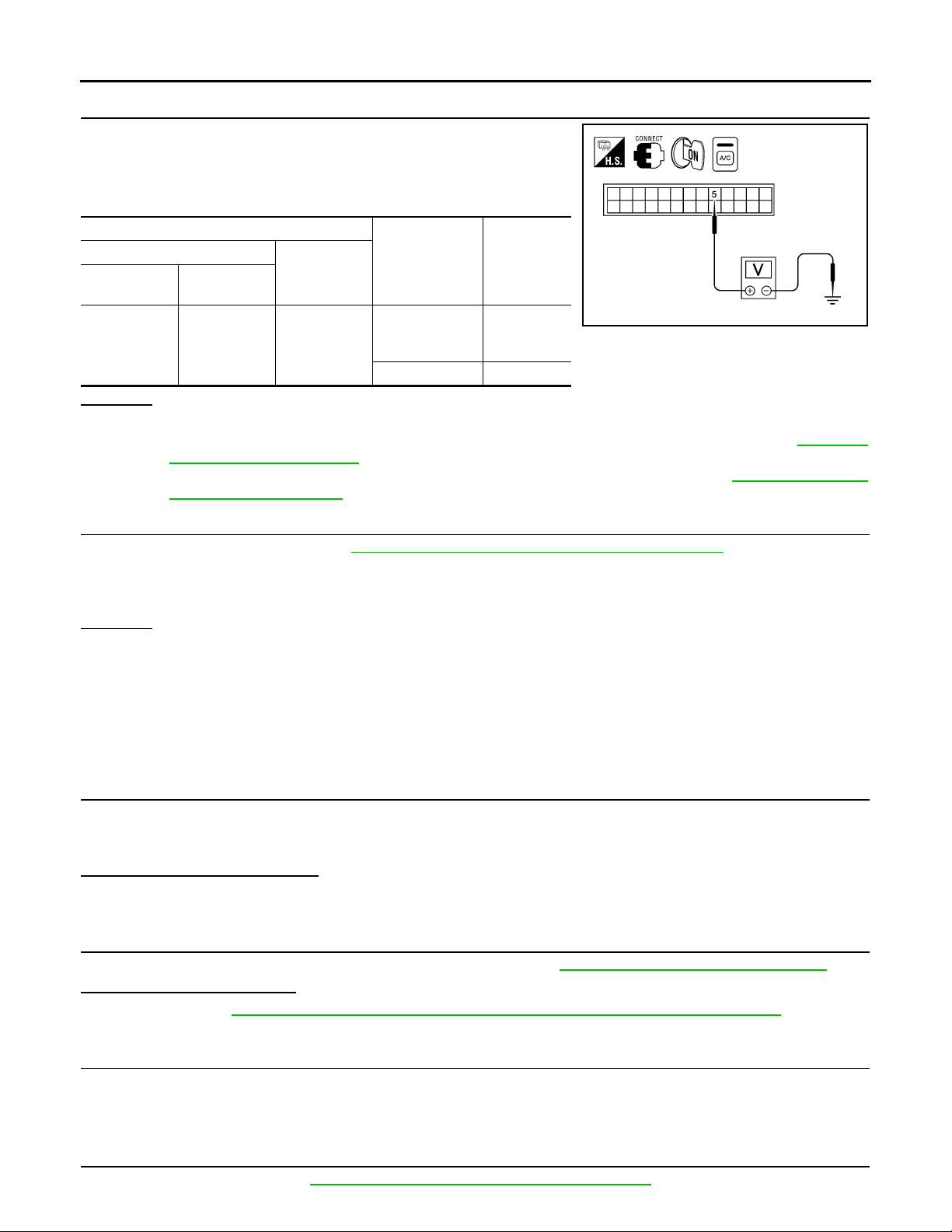
TROUBLE DIAGNOSIS
Revision: October 2008
2009 Quest
< SERVICE INFORMATION >
11.CHECK VOLTAGE FOR FRONT AIR CONTROL (FAN ON SIGNAL)
1. Reconnect BCM connector and front air control connector.
2. Turn ignition switch ON.
3. Check voltage between front air control harness connector M49
terminal 5 and ground.
Terminals
(+)
Front air control connector
M49 5 Ground
OK or NG
OK >> GO TO 12.
NG-1 >> If the voltage is approx. 5V when blower motor is ON, replace front air control. Refer to MTC-113,
NG-2 >> If the voltage is approx. 0V when blower motor is OFF, replace BCM. Refer to BCS-17, "Removal
Terminal No.
"Removal and Installation".
and Installation of BCM".
(-)
Condition
A/C switch: ON
Blower motor
operates
A/C switch: OFF 5V
Voltage
(Approx.)
WJIA2116E
0V
12.CHECK CAN COMMUNICATION
Check CAN communication. Refer to ATC-27, "CAN Communication System Description"
•BCM – ECM
• ECM – IPDM E/R
• ECM – Front air control
OK or NG
OK >> Inspection End.
NG >> Repair or replace malfunctioning part(s).
.
Insufficient Cooling INFOID:0000000004277569
SYMPTOM: Insufficient cooling
INSPECTION FLOW
1.CONFIRM SYMPTOM BY PERFORMING OPERATIONAL CHECK - TEMPERATURE DECREASE
1. Turn front and rear temperature control dial counterclockwise to maximum cold.
2. Press the A/C switch.
3. Check for cold air at discharge air outlets.
Can the symptom be duplicated?
YES >> GO TO 3.
NO >> GO TO 2.
2.CHECK FOR ANY SYMPTOMS
Perform a complete operational check for any symptoms. Refer to MTC-45, "Operational Check (Front)"
Does another symptom exist?
YES >> Refer to MTC-29, "How to Perform Trouble Diagnosis for Quick and Accurate Repair".
NO >> System OK.
.
3.CHECK FOR SERVICE BULLETINS
Check for any service bulletins.
4.PERFORM SELF-DIAGNOSIS
Perform self-diagnosis Refer to MTC-44, "A/C System Self-Diagnosis Function"
>> GO TO 4.
.
MTC-94
Page 95

TROUBLE DIAGNOSIS
Revision: October 2008
2009 Quest
< SERVICE INFORMATION >
OK or NG
OK >> GO TO 5.
NG >> Refer to MTC-44, "A/C System Self-Diagnosis Function"
.
5.CHECK DRIVE BELTS
Check compressor belt tension. Refer to EM-12, "Checking Drive Belts"
OK or NG
OK >> GO TO 6.
NG >> Adjust or replace compressor belt. Refer to EM-12
.
6.CHECK AIR MIX DOOR OPERATION
Check and verify air mix door mechanism for smooth operation.
Does air mix door operate correctly?
YES > >GO TO 7.
NO >> Repair or replace air mix door control linkage.
7.CHECK COOLING FAN MOTOR OPERATION
A
B
.
C
D
E
Check and verify cooling fan motor for smooth operation. Refer to EC-478, "Description"
Does cooling fan motor operate correctly?
YES > >GO TO 8.
NO >> Check cooling fan motor. Refer to EC-478
.
.
8.CHECK RECOVERY/RECYCLING EQUIPMENT BEFORE USAGE
Check recovery/recycling equipment before connecting to vehicle. Verify there is no pressure in the recovery/
recycling equipment by checking the gauges. If pressure exists, recover refrigerant from equipment lines.
>> GO TO 9.
9.CHECK REFRIGERANT PURITY
1. Connect recovery/recycling equipment to vehicle.
2. Confirm refrigerant purity in supply tank using recovery/recycling and refrigerant identifier.
OK or NG
OK >> GO TO 10.
NG >> Check contaminated refrigerant. Refer to MTC-3, "Contaminated Refrigerant"
.
10.CHECK FOR EVAPORATOR FREEZE UP
Start engine and run A/C. Check for evaporator freeze up.
Does evaporator freeze up?
YES >>Perform diagnostic work flow. Refer to "DIAGNOSTIC WORK FLOW".
NO >> GO TO 11.
11.CHECK REFRIGERANT PRESSURE
F
G
H
I
MTC
K
L
M
Check refrigerant pressure with manifold gauge connected. Refer to "TEST READING".
OK or NG
OK >> Perform diagnostic work flow. Refer to "DIAGNOSTIC WORK FLOW".
NG >> GO TO 12.
12.CHECK AIR DUCTS
Check ducts for air leaks.
OK or NG
OK >> System OK.
NG >> Repair air leaks.
DIAGNOSTIC WORK FLOW
N
O
P
MTC-95
Page 96

< SERVICE INFORMATION >
Revision: October 2008
2009 Quest
TROUBLE DIAGNOSIS
*1 MTC-161, "Checking System for
Leaks Using the Fluorescent Dye
Leak Detector"
*4 "Trouble Diagnoses for Abnormal
Pressure"
*2 MTC-147, "Removal and Installation
for Compressor"
*5 MTC-54, "Air Mix Door Motor Circuit"
MTC-96
AWIIA0999GB
*3 "PERFORMANCE CHART"
Page 97

< SERVICE INFORMATION >
Revision: October 2008
2009 Quest
TROUBLE DIAGNOSIS
A
B
C
D
E
F
G
AWIIA1000GB
*1 MTC-119, "Removal and Installation" *2 MTC-69, "Front Blower Motor Circuit" *3 EM-12, "Checking Drive Belts"
*4 EM-12, "Checking Drive Belts" *5 MTC-147, "Removal and Installation
for Compressor"
H
I
MTC
K
L
M
N
O
PERFORMANCE CHART
Test Condition
Testing must be performed as follows:
P
MTC-97
Page 98

TROUBLE DIAGNOSIS
Revision: October 2008
2009 Quest
< SERVICE INFORMATION >
Vehicle location Indoors or in the shade (in a well-ventilated place)
Doors Closed
Windows Open
Hood Open
TEMP. Max. COLD
Mode dial
Recirculation (REC) switch
Blower speed (FR and RR)
Engine speed Idle speed
RR system ON
Operate the air conditioning system for 10 minutes before taking measurements.
TEST READING
Recirculating-to-discharge Air Temperature Table
(Ventilation) set
(Recirculation) set
Max. speed set
Inside air (Recirculating air) at blower assembly inlet
Relative humidity
%
50-70
Air temperature
°C (°F)
25 (77) 9.7 - 13.7 (49 - 57)
30 (86) 12.6 - 16.6 (55 - 62)
35 (95) 14.9 - 19.9 (59 - 68)
40 (104) 17.3 - 23.3 (63 - 74)
Discharge air temperature at center ventilator
°C (°F)
Ambient Air Temperature-to-operating Pressure Table
Relative humidity
%
50-70
Ambient air
Air temperature
°C (°F)
25 (77)
30 (86)
35 (95)
40 (104)
High-pressure (Discharge side)
kPa (kg/cm
1,059 - 1,294
(10.8 - 13.2, 153.6 - 187.7)
1,206 - 1,481
(12.3 - 15.1, 174.9 - 214.8)
1,393 - 1,706
(14.2 - 17.4, 202.0 - 247.5)
1,510 - 1,844
(15.4 - 18.8, 219.0 - 267.4)
2
, psi)
Low-pressure (Suction side)
kPa (kg/cm2, psi)
216 - 255
(2.2 - 2.6, 31.3 - 37.0)
255 - 304
(2.6 - 3.1, 37.0 - 44.1)
275 - 343
(2.8 - 3.5, 39.8 - 49.8)
343 - 422
(3.5 - 4.3, 49.8 - 61.2)
Trouble Diagnoses for Abnormal Pressure
Whenever system′s high and/or low side pressure is unusual, diagnose using a manifold gauge. The marker
above the gauge scale in the following tables indicates the standard (usual) pressure range. Since the standard (usual) pressure, however, differs from vehicle to vehicle, refer to above table (Ambient air temperatureto-operating pressure table).
Both High- and Low-pressure Sides are Too High
MTC-98
Page 99

< SERVICE INFORMATION >
Revision: October 2008
2009 Quest
TROUBLE DIAGNOSIS
Gauge indication Refrigerant cycle Probable cause Corrective action
Both high- and low-pressure sides
are too high.
AC359A
Pressure is reduced soon after water is splashed on condenser.
Air suction by cooling fan is insufficient.
• Low-pressure pipe is not
cold.
• When compressor is
stopped high-pressure value quickly drops by ap prox-
imately 196 kPa (2 kg/cm
28 psi). It then decreases
gradually thereafter.
Engine tends to overheat.
• An area of the low-pressure
pipe is colder than areas
near the evaporator outlet.
• Plates are sometimes covered with frost.
2
Excessive refrigerant char ge in
refrigeration cycle.
Insufficient condenser cooling
performance.
↓
1. Condenser fins are
clogged.
2. Improper fan rotation of
cooling fan.
Poor heat exchange in condenser.
(After compressor operation
stops, high-pressure decreases too slowly.)
,
↓
Air in refrigeration cycle.
Engine cooling systems malfunction.
• Excessive liquid refrigerant
on low-pressure side.
• Excessive refrigerant dis-
charge flow.
• Expansion valve is open a lit-
tle compared with the specification.
↓
Improper expansion valve adjustment.
Reduce refrigerant until specified pressure is obtained.
• Clean condenser.
• Check and repair cooling fan
as necessary.
Evacuate and recharge system.
Check and repair engine cooling system.
Replace expansion valve.
A
B
C
D
E
F
G
H
I
High-pressure Side is Too High and Low-pressure Side is Too Low
Gauge indication Refrigerant cycle Probable cause Corrective action
High-pressure side is too high a nd
low-pressure side is too low.
Upper side of condenser and
high-pressure side are hot,
however, liquid tank is not so
hot.
AC360A
High-pressure tube or parts located between compressor
and condenser are clogged or
crushed.
High-pressure Side is Too Low and Low-pressure Side is Too High
Gauge indication Refrigerant cycle Probable cause Corrective action
Compressor pressure opera-
High-pressure side is too low and
low-pressure side is too high.
AC356A
High- and low-pressure sides
become equal soon after compressor operation stops.
No temperature difference between high- and low-pressure
sides.
tion is improper.
↓
Damaged inside compressor
packings.
Compressor pressure operation is improper.
↓
Damaged inside compressor
packings.
• Check and repair or replace
malfunctioning parts.
• Check oil for contamination.
Replace compressor.
Replace compressor.
MTC
K
L
M
N
O
P
Both High- and Low-pressure Sides are Too Low
MTC-99
Page 100

< SERVICE INFORMATION >
Revision: October 2008
2009 Quest
Gauge indication Refrigerant cycle Probable cause Corrective action
Both high- and low-pressure sides
are too low.
AC353A
TROUBLE DIAGNOSIS
• There is a big temperature
difference between liquid
tank outlet and inlet. Outlet
temperature is extremely
low.
• Liquid tank inlet and expansion valve are frosted.
• Temperature of expansion
valve inlet is extremely low
as compared with areas
near liquid tank.
• Expansion valve inlet may
be frosted.
• Temperature difference occurs somewhere in highpressure side.
Expansion valve and liquid
tank are warm or only cool
when touched.
There is a big temperature difference between expansion
valve inlet and outlet while the
valve itself is frosted.
An area of the low-pressure
pipe is colder than areas near
the evaporator outlet.
Air flow volume is too low. Evaporator is frozen.
Liquid tank inside is slightly
clogged.
High-pressure pipe located between liquid tank and expansion valve is clogged.
Low refrigerant charge.
↓
Leaking fittings or components.
Expansion valve closes a little
compared with the specification.
↓
1. Improper expansion
valve adjustment.
2. Malfunctioning expansion
valve.
3. Outlet and inlet may be
clogged.
Low-pressure pipe is clogged
or crushed.
• Replace liquid tank.
• Check oil for contamination.
• Check and repair malfunctioning parts.
• Check oil for contamination.
Check refrigerant system for
leaks. Refer to MTC-161,
"Checking of Refrigerant
Leaks".
• Remove foreign particles by
using compressed air.
• Check oil for contamination.
• Check and repair malfunctioning parts.
• Check oil for contamination.
• Check intake sensor circuit.
Refer to MTC-110, "Intake
Sensor Circuit".
• Replace compressor.
Low-pressure Side Sometimes Becomes Negative
Low-pressure side sometimes becomes negative.
Low-pressure Side Becomes Negative
Gauge indication Refrigerant cycle Probable cause Corrective action
• Air conditioning system does
not function and does not cyclically cool the compartment air.
• The system constantly functions for a certain period of
time after compressor is
stopped and restarted.
AC354A
Refrigerant does not discha rge
cyclically.
↓
Moisture is frozen at expansion valve outlet and inlet.
↓
Water is mixed with refrigerant.
• Drain water from refrigerant
or replace refrigerant.
• Replace liquid tank.
MTC-100
 Loading...