

Page 1

Page 2

Component Parts Location ................................... 54
Revision: 2008 October 2009 Murano
Component Description .........................................55
DTC Logic ..................................... .......................... 70
Diagnosis Procedure ..... ... .......................................70
FUEL FILLER LID OPENER .............................56
Component Parts Location .....................................56
INTEGRATED HOMELINK TRANSMITTER .....57
Component Description .......................................... 57
DIAGNOSIS SYSTEM (BCM) ............................58
COMMON ITEM ................................. .... ................... 58
COMMON ITEM : CONSULT-III Function (BCM -
COMMON ITEM) ....................................................
DOOR LOCK ............................................................. 59
DOOR LOCK : CONSULT-III Function (BCM -
DOOR LOCK) .........................................................
INTELLIGENT KEY ................................................... 61
INTELLIGENT KEY : CONSULT-III Function
(BCM - INTELLIGENT KEY) ...................................
TRUNK ...................................................................... 64
TRUNK : CONSULT-III Function (BCM - TRUNK) ...64
58
59
61
DIAGNOSIS SYSTEM (AUTOMATIC BACK
DOOR CONTROL UNIT) ...................................
CONSULT-III Function (AUTOMATIC BACK
DOOR CONTROL UNIT) ........................................
66
66
COMPONENT DIAGNOSIS ........................ 67
U1000 CAN COMM CIRCUIT ............................67
BCM .............................. ...... ....... ...... ....... ...... ....... ...... 67
BCM : Description ................................................... 67
BCM : DTC Logic .................................................... 67
BCM : Diagnosis Procedure ................................... 67
AUTOMATIC BACK DOOR CONTROL UNIT .......... 67
AUTOMATIC BACK DOOR CONTROL UNIT :
Description ....................... .......................... .............
AUTOMATIC BACK DOOR CONTROL UNIT :
DTC Logic ...............................................................
AUTOMATIC BACK DOOR CONTROL UNIT : Di-
agnosis Procedure ..................................................
U1010 CONTROL UNIT (CAN) .........................69
BCM .............................. ...... ....... ...... ....... ...... ....... ...... 69
BCM : DTC Logic .................................................... 69
BCM : Diagnosis Procedure ................................... 69
BCM : Special Repair Requirement ........................ 69
AUTOMATIC BACK DOOR CONTROL UNIT .......... 69
AUTOMATIC BACK DOOR CONTROL UNIT :
DTC Logic ...............................................................
AUTOMATIC BACK DOOR CONTROL UNIT : Di-
agnosis Procedure ..................................................
B2401 IGNITION POWER SUPPLY CIRCUIT ...70
Description ....................... .......................... ............. 70
67
67
67
69
69
B2403 ENCODER .............................................. 71
Description ..............................................................71
DTC Logic ..................................... .......................... 71
Diagnosis Procedure ..... ... .......................................71
B2409 HALF LATCH SWITCH .......................... 74
Description ..............................................................74
DTC Logic ..................................... .......................... 74
Diagnosis Procedure ..... ... .......................................74
Component Inspection ............................................75
B2416 TOUCH SENSOR RH ............................ 76
Description ..............................................................76
DTC Logic ..................................... .......................... 76
Diagnosis Procedure ..... ... .......................................76
Component Inspection ............................................77
B2417 TOUCH SENSOR LH ............................. 78
Description ..............................................................78
DTC Logic ..................................... .......................... 78
Diagnosis Procedure ..... ... .......................................78
Component Inspection ............................................79
B2418 CLUTCH POWER SUPPLY CIRCUIT ... 80
Description ..............................................................80
DTC Logic ..................................... .......................... 80
Diagnosis Procedure ..... ... .......................................80
B2419 OPEN SWITCH ...................................... 82
Description ..............................................................82
DTC Logic ..................................... .......................... 82
Diagnosis Procedure ..... ... .......................................82
Component Inspection ............................................83
B2420 CLOSE SWITCH .................................... 85
Description ..............................................................85
DTC Logic ..................................... .......................... 85
Diagnosis Procedure ..... ... .......................................85
Component Inspection ............................................86
B2421 CLUTCH OPERATION TIME ................. 87
Description ..............................................................87
DTC Logic ..................................... .......................... 87
Diagnosis Procedure ..... ... .......................................87
B2422 BACK DOOR STATE ............................. 88
Description ..............................................................88
DTC Logic ..................................... .......................... 88
Diagnosis Procedure ..... ... .......................................88
Component Inspection ............................................89
B2423 AUTOMATIC BACK DOOR MOTOR
OPERATION TIME ............................................
Description ..............................................................90
DTC Logic ..................................... .......................... 90
Diagnosis Procedure ..... ... .......................................90
90
B2424 CLOSURE CONDITION ......................... 92
DLK-2
Page 3

Description ..............................................................
Revision: 2008 October 2009 Murano
DTC Logic ...............................................................92
Diagnosis Procedure .......... .....................................92
Component Inspection ............................................93
92
B2621 INSIDE KEY ANTENNA 1 ......................95
Description ..............................................................95
DTC Logic ...............................................................95
Diagnosis Procedure .......... .....................................95
B2622 INSIDE KEY ANTENNA 2 ......................97
Description ..............................................................97
DTC Logic ...............................................................97
Diagnosis Procedure .......... .....................................97
B2623 INSIDE KEY ANTENNA 3 ......................99
Description ..............................................................99
DTC Logic ...............................................................99
Diagnosis Procedure .......... .....................................99
POWER SUPPLY AND GROUND CIRCUIT ....101
BCM (BODY CONTROL MODULE) ........................ 101
BCM (BODY CONTROL MODULE) : Diagnosis
Procedure ..................... ................ ................ .........
AUTOMATIC BACK DOOR CONTROL UNIT ........ 101
AUTOMATIC BACK DOOR CONTROL UNIT : Di-
agnosis Procedure ........................................... .....
101
101
DOOR SWITCH ................................................103
WITH AUTOMATIC BACK DOOR ..........................103
WITH AUTOMATIC BACK DOOR : Description ...103
WITH AUTOMATIC BACK DOOR :
Component Function Check ................................
WITH AUTOMATIC BACK DOOR : Diagnosis
Procedure ..................... ................ ................ .........
WITH AUTOMATIC BACK DOOR : Component
Inspection ..................... .........................................
WITHOUT AUTOMATIC BACK DOOR ...................106
WITHOUT AUTOMATIC BACK DOOR : Descrip-
tion ........................................................................
WITHOUT AUTOMATIC BACK DOOR :
Component Function Check ................................
WITHOUT AUTOMATIC BACK DOOR : Diagno-
sis Procedure ........................................................
WITHOUT AUTOMATIC BACK DOOR : Compo-
nent Inspection ............. ... ... ...................................
103
103
105
106
106
106
108
DOOR LOCK AND UNLOCK SWITCH ............110
PASSENGER SIDE : Diagnosis Procedure ..........110
DOOR LOCK ACTUATOR ..............................112
DRIVER SIDE ...........................................................112
DRIVER SIDE : Description ...................................112
DRIVER SIDE : Component Function Check ......112
DRIVER SIDE : Diagnosis Procedure ...................112
PASSENGER SIDE ..................................................112
PASSENGER SIDE : Description ..........................113
PASSENGER SIDE :
Component Function Check ................................
PASSENGER SIDE : Diagnosis Procedure ..........113
REAR LH ..................................................................113
REAR LH : Description .................................... ... ...113
REAR LH : Component Function Check ..............114
REAR LH : Diagnosis Procedure ............... ............114
REAR RH .................................................................114
REAR RH : Description .........................................114
REAR RH : Component Function Check .............114
REAR RH : Diagnosis Procedure ..........................115
113
BACK DOOR OPENER ACTUATOR .............116
Description ....................... ...... ....... ...... ....... ...... ......116
Component Function Check ................................116
Diagnosis Procedure .............................................116
KEY CYLINDER SWITCH ...............................118
Description ....................... ...... ....... ...... ....... ...... ......118
Component Function Check ..................................118
Diagnosis Procedure .............................................118
Component Inspection ...........................................119
REMOTE KEYLESS ENTRY RECEIVER .......120
Description ....................... ...... ....... ...... ....... ...... ......120
Component Function Check ................................120
Diagnosis Procedure .............................................120
BACK DOOR OPENER SWITCH ...................123
Description ....................... ...... ....... ...... ....... ...... ......123
Component Function Check ................................123
Diagnosis Procedure .............................................123
Component Inspection ...........................................124
DOOR REQUEST SWITCH ............................125
Description ....................... ...... ....... ...... ....... ...... ......125
Component Function Check ................................125
Diagnosis Procedure .............................................125
Component Inspection ...........................................126
A
B
C
D
E
F
G
H
I
J
DLK
L
M
N
O
DRIVER SIDE .......................................................... 110
DRIVER SIDE : Description ..................................110
DRIVER SIDE : Component Function Check ...... 110
DRIVER SIDE : Diagnosis Procedure ................... 110
PASSENGER SIDE .................................................110
PASSENGER SIDE : Description .........................110
PASSENGER SIDE :
Component Function Check ................................
110
BACK DOOR REQUEST SWITCH .................127
Description ....................... ...... ....... ...... ....... ...... ......127
Component Function Check ................................127
Diagnosis Procedure .............................................127
Component Inspection ...........................................128
UNLOCK SENSOR .........................................129
Description ....................... ...... ....... ...... ....... ...... ......129
Component Function Check ................................129
DLK-3
P
Page 4

Diagnosis Procedure ............................................. 129
Revision: 2008 October 2009 Murano
Component Inspection ...........................................130
OUTSIDE KEY ANTENNA .............................. 131
Description ....................... .......................... ............131
Component Function Check ................................131
Diagnosis Procedure ............................................. 131
INTELLIGENT KEY WARNING BUZZER ....... 133
Description ....................... .......................... ............133
Component Function Check ................................133
Diagnosis Procedure ............................................. 133
Component Inspection ...........................................134
INTELLIGENT KEY ......................................... 135
Description ....................... .......................... ............135
Component Function Check ................................135
Diagnosis Procedure ............................................. 135
Component Inspection ...........................................135
Special Repair Requirement ..................................136
KEY SLOT ....................................................... 137
Description ....................... .......................... ............137
Component Function Check ................................137
Diagnosis Procedure ............................................. 137
Component Inspection ...........................................138
KEY SLOT ILLUMINATION ............................. 139
Description ....................... .......................... ............139
Component Function Check ................................139
Diagnosis Procedure ............................................. 139
Component Inspection ...........................................140
HORN FUNCTION ........................................... 141
Description ....................... .......................... ............141
Component Function Check ................................141
Diagnosis Procedure ............................................141
COMBINATION METER DISPLAY FUNC-
TION .................................................................
Description ....................... .......................... ............143
Component Function Check ................................143
Diagnosis Procedure ............................................. 143
143
BUZZER (COMBINATION METER) ................ 144
Description ....................... .......................... ............144
Component Function Check ................................144
Diagnosis Procedure ............................................. 144
KEY WARNING LAMP .................................... 145
Description ....................... .......................... ............145
Component Function Check ................................145
Diagnosis Procedure ............................................. 145
HAZARD FUNCTION ....................................... 146
Description ....................... .......................... ............146
Component Function Check ................................146
Diagnosis Procedure ............................................. 146
AUTOMATIC BACK DOOR CLOSE SWITCH . 147
Description ....................... .......................... ............147
Component Function Check .............................. .. 147
Diagnosis Procedure ..... ... ..................................... 147
Component Inspection .......................................... 148
AUTOMATIC BACK DOOR MAIN SWITCH ....149
Description ............................................................ 149
Component Function Check .............................. .. 149
Diagnosis Procedure ..... ... ..................................... 149
Component Inspection .......................................... 150
AUTOMATIC BACK DOOR SWITCH ..............151
Description ............................................................ 151
Component Function Check .............................. .. 151
Diagnosis Procedure ..... ... ..................................... 151
Component Inspection .......................................... 152
OPEN SWITCH .................................................153
Description ............................................................ 153
Component Function Check ................................. 153
Diagnosis Procedure ..... ... ..................................... 153
Component Inspection .......................................... 154
CLOSE SWITCH ...............................................155
Description ............................................................ 155
Component Function Check ................................. 155
Diagnosis Procedure ..... ... ..................................... 155
Component Inspection .......................................... 156
HALF LATCH SWITCH ....................................157
Description ............................................................ 157
Component Function Check ................................. 157
Diagnosis Procedure ..... ... ..................................... 157
Component Inspection .......................................... 158
TOUCH SENSOR .............................................159
RH ................................ ............................................ 159
RH : Description .................................................... 159
RH : Component Function Check ........................ 159
RH : Diagnosis Procedure .................................... 159
RH : Component Inspection .................................. 160
LH ............................................................................ 160
LH : Description .................................................... 160
LH : Component Function Check ........................ 160
LH : Diagnosis Procedure .....................................161
LH : Component Inspection .................................. 162
ENCODER ........................................................163
Description ............................................................ 163
Component Function Check ................................. 163
Diagnosis Procedure ..... ... ..................................... 163
CLUTCH ...........................................................165
Description ............................................................ 165
Diagnosis Procedure ..... ... ..................................... 165
AUTOMATIC BACK DOOR MOTOR ...............166
Description ............................................................ 166
Diagnosis Procedure ..... ... ..................................... 166
BACK DOOR CLOSURE MOTOR ...................168
DLK-4
Page 5

Description ............................................................
Revision: 2008 October 2009 Murano
Diagnosis Procedure .......... ...................................168
168
ALL DOOR ...............................................................270
ALL DOOR : Diagnosis Procedure ........................270
A
AUTOMATIC BACK DOOR WARNING BUZZ-
ER .....................................................................
Description ............................................................169
Diagnosis Procedure .......... ...................................169
169
GROUND CIRCUIT ..........................................170
AUTOMATIC BACK DOOR CONTROL UNIT ........ 170
AUTOMATIC BACK DOOR CONTROL UNIT :
Component Function Check ................................
AUTOMATIC BACK DOOR CONTROL UNIT : Di-
agnosis Procedure ........................................... .....
170
170
INTEGRATED HOMELINK TRANSMITTER ....171
Description ............................................................171
Component Function Check ................................171
Diagnosis Procedure .......... ...................................171
POWER DOOR LOCK SYSTEM ......................173
Wiring Diagram - POWER DOOR LOCK SYSTEM
- .............................................................................
173
INTELLIGENT KEY SYSTEM ..........................181
Wiring Diagram - INTELLIGENT KEY SYSTEM - ..181
BACK DOOR OPENER SYSTEM ....................205
Wiring Diagram - BACK DOOR OPENER - ..........205
FUEL FILLER LID OPENER ............................209
Wiring Diagram - FUEL LID OPENER - ................209
INTEGRATED HOMELINK TRANSMITTER
SYSTEM ...........................................................
Wiring Diagram - INTEGRATED HOMELINK
TRANSMITTER SYSTEM - ...................................
211
211
ECU DIAGNOSIS ....................................... 213
BCM (BODY CONTROL MODULE) .................213
Reference Value ...................................................213
Wiring Diagram - BCM - ........................................237
Fail-safe ................................................................251
DTC Inspection Priority Chart .............................254
DTC Index ............................................................255
AUTOMATIC BACK DOOR CONTROL UNIT ..258
Reference Value ...................................................258
Wiring Diagram - AUTOMATIC BACK DOOR
CONTROL SYSTEM - ...........................................
Fail Safe ...............................................................268
DTC Inspection Priority Chart .............................268
DTC Index ............................................................268
262
SYMPTOM DIAGNOSIS ............................270
DOOR DOES NOT LOCK/UNLOCK WITH
DOOR LOCK AND UNLOCK SWITCH ............
270
DRIVER SIDE ...........................................................270
DRIVER SIDE : Diagnosis Procedure ...................270
PASSENGER SIDE ..................................................270
PASSENGER SIDE : Diagnosis Procedure ..........271
REAR LH ..................................................................271
REAR LH : Diagnosis Procedure ............... ............271
REAR RH .................................................................271
REAR RH : Diagnosis Procedure ..........................271
DOOR DOES NOT LOCK/UNLOCK WITH
DOOR KEY CYLINDER OPERATION ............
Diagnosis Procedure .............................................272
272
VEHICLE SPEED SENSING AUTO LOCK
OPERATION DOES NOT OPERATE .............
Diagnosis Procedure .............................................273
273
IGN OFF INTERLOCK DOOR LOCK/UN-
LOCK FUNCTION DOES NOT OPERATE .....
Diagnosis Procedure .............................................274
274
P RANGE INTERLOCK DOOR LOCK/UN-
LOCK FUNCTION DOES NOT OPERATE .....
Diagnosis Procedure .............................................275
275
POWER WINDOW DOWN FUNCTION DO ES
NOT OPERATE WITH KEY CYLINDER OP-
ERATION .........................................................
Diagnosis Procedure .............................................276
276
DOOR DOES NOT LOCK/UNLOCK WITH IN-
TELLIGENT KEY ............................................
Description ....................... ...... ....... ...... ....... ...... ......277
Diagnosis Procedure .............................................277
277
SELECTIVE UNLOCK FUNCTION DOES
NOT OPERATE WITH INTELLIGENT KEY ....
Description ....................... ...... ....... ...... ....... ...... ......278
Diagnosis Procedure .............................................278
278
POWER WINDOW DOWN FUNCTION DO ES
NOT WORK WHEN OPERATING WITH IN-
TELLIGENT KEY ............................................
Description ....................... ...... ....... ...... ....... ...... ......279
Diagnosis Procedure .............................................279
279
PANIC ALARM FUNCTION DOES NOT OP-
ERATE .............................................................
Description ....................... ...... ....... ...... ....... ...... ......280
Diagnosis Procedure .............................................280
280
HAZARD AND HORN REMINDER DOES
NOT OPERATE ...............................................
Description ....................... ...... ....... ...... ....... ...... ......281
Diagnosis Procedure .............................................281
281
B
C
D
E
F
G
H
I
J
DLK
L
M
N
O
P
DLK-5
Page 6

AUTO DOOR LOCK OPERATION DOES NOT
Revision: 2008 October 2009 Murano
OPERATE ........................................................
Description ....................... .......................... ............282
Diagnosis Procedure ............................................. 282
282
ANY DOOR OPEN TO ALL DOORS CLOSED :
Description ............................................................
ANY DOOR OPEN TO ALL DOORS CLOSED :
Diagnosis Procedure ..... ... .....................................
295
295
DOOR DOES NOT LOCK/UNLOCK WITH
DOOR REQUEST SWITCH .............................
DRIVER SIDE .................................. ... ...................... 283
DRIVER SIDE : Description ...................................283
DRIVER SIDE : Diagnosis Procedure ...................283
PASSENGER SIDE ..................................................283
PASSENGER SIDE : Description ..........................283
PASSENGER SIDE : Diagnosis Procedure ..........284
BACK DOOR ............................................................284
BACK DOOR : Description .............. .... ... ... ............284
BACK DOOR : Diagnosis Procedure .....................285
283
SELECTIVE UNLOCK FUNCTION DOES
NOT OPERATE WITH DOOR REQUEST
SWITCH ...........................................................
Description ....................... .......................... ............286
Diagnosis Procedure ............................................. 286
286
HAZARD AND BUZZER REMINDER DOES
NOT OPERATE ...............................................
Description ....................... .......................... ............287
Diagnosis Procedure ............................................. 287
287
KEY REMINDER FUNCTION DOE S NOT OP -
ERATE .............................................................
Description ....................... .......................... ............288
Diagnosis Procedure ............................................. 288
288
KEY WARNING DOES NOT OPERATE ......... 289
Description ....................... .......................... ............289
Diagnosis Procedure ............................................. 289
OFF POSITION WARNING DOES NOT OP-
ERATE .............................................................
Description ....................... .......................... ............290
Diagnosis Procedure ............................................. 290
290
P POSITION WARNING DOES NOT OPER-
ATE ..................................................................
Description ....................... .......................... ............291
Diagnosis Procedure ............................................. 291
291
ACC WARNING DOES NOT OPERATE ......... 293
Description ....................... .......................... ............293
Diagnosis Procedure ............................................. 293
PUSH-BUTTON IGNITION SWITCH OPERATION . 295
PUSH-BUTTON IGNITION SWITCH OPERA-
TION : Description ................................................
PUSH-BUTTON IGNITION SWITCH OPERA-
TION : Diagnosis Procedure .................................
TAKE AWAY THROUGH WINDOW ....................... 296
TAKE AWAY THROUGH WINDOW : Description . 296
TAKE AWAY THROUGH WINDOW : Diagnosis
Procedure .............................................................
INTELLIGENT KEY IS REMOVED FROM KEY
SLOT .......................................................................
INTELLIGENT KEY IS REMOVED FROM KEY
SLOT : Description ........... ... ... .... ...........................
INTELLIGENT KEY IS REMOVED FROM KEY
SLOT : Diagnosis Procedure ................................
296
296
297
297
297
298
INTELLIGENT KEY LOW BATTERY WARN-
ING DOES NOT OPERATE ..............................
Description ............................................................ 299
Diagnosis Procedure ..... ... ..................................... 299
299
DOOR LOCK OPERATION WARNING DOES
NOT OPERATE WITH DOOR REQUEST
SWITCH ............................................................
Description ............................................................ 300
Diagnosis Procedure ..... ... ..................................... 300
300
KEY ID WARNING DOES NOT OPERATE .....301
Description ............................................................ 301
Diagnosis Procedure ..... ... ..................................... 301
INTELLIGENT KEY LOW BATTERY WARN-
ING DOES NOT OPERATE ..............................
Description ............................................................ 302
Diagnosis Procedure ..... ... ..................................... 302
302
INTEGRATED HOMELINK TRANSMITTER
DOES NOT OPERATE .....................................
Description ............................................................ 303
Diagnosis Procedure ..... ... ..................................... 303
303
AUTOMATIC BACK DOOR OPERATION
DOES NOT OPERATE .....................................
ALL SWITCHES .............................. ... ... ... .... ... ... ..... 304
ALL SWITCHES : Diagnosis Procedure ............... 304
304
TAKE AWAY WARNING DOES NOT OPER-
ATE ..................................................................
DOOR IS OPEN .......................................................294
DOOR IS OPEN : Description ...............................294
DOOR IS OPEN : Diagnosis Procedure ................294
ANY DOOR OPEN TO ALL DOORS CLOSED .......295
294
AUTOMATIC BACK DOOR SWITCH ..................... 304
AUTOMATIC BACK DOOR SWITCH : Diagnosis
Procedure .............................................................
AUTOMATIC BACK DOOR CLOSE SWITCH ........ 304
AUTOMATIC BACK DOOR CLOSE SWITCH : Di-
agnosis Procedure ................................................
DLK-6
304
304
Page 7

INTELLIGENT KEY .................................................
Revision: 2008 October 2009 Murano
INTELLIGENT KEY : Diagnosis Procedure ..........305
BACK DOOR OPENER SWITCH ............................305
BACK DOOR OPENER SWITCH : Diagnosis Pro-
cedure ...................................................................
CLOSURE FUNCTION ............................................306
CLOSURE FUNCTION : Diagnosis Procedure .....306
BACK DOOR OPEN/CLOSE FUNCTION ...............306
BACK DOOR OPEN/CLOSE FUNCTION : Diag-
nosis Procedure ....................................................
305
305
306
AUTOMATIC BACK DOOR WARNING DOES
NOT OPERATE ................................................
BUZZER ................................ .............................. ..... 308
BUZZER : Diagnosis Procedure ........................... 308
HAZARD WARNING LAMP ....................................308
HAZARD WARNING LAMP : Diagnosis Proce-
dure .......................................................................
308
308
AUTOMATIC BACK DOOR FUNCTIONS DO
NOT CANCEL ..................................................
AUTOMATIC BACK DOOR MAIN SWITCH ...........309
AUTOMATIC BACK DOOR MAIN SWITCH : Di-
agnosis Procedure ........................................... .....
309
309
SQUEAK AND RATTLE TROUBLE DIAG-
NOSES .............................................................
Work Flow .............................................................310
Inspection Procedure ............................................312
Diagnostic Worksheet ...........................................314
310
PRECAUTION ............................................316
PRECAUTIONS ................................................316
Precaution for Supplemental Restraint System
(SRS) "AIR BAG" and "SEAT BELT PRE-TEN-
SIONER" ...............................................................
Precaution for Procedure without Cowl Top Cover ..316
Precaution Necessary for Steering Wheel Rota-
tion after Battery Disconnect ............... ..................
Work ................................ ...................................... 317
316
316
PREPARATION .........................................318
PREPARATION ................................................318
Special Service Tools ...... ... .... ... ... .........................318
Commercial Service Tools ....................................318
HOOD HINGE ..........................................................321
HOOD HINGE : Exploded View .............................322
HOOD HINGE : Removal and Installation .............322
HOOD STAY ............................................................322
HOOD STAY : Exploded View ............ ... .... ... ... ......323
HOOD STAY : Removal and Installation ...............323
HOOD STAY : Disposal ............. ... ... ... ... ................324
RADIATOR CORE SUPPORT ........................325
Exploded View .......................................................325
Removal and Installation .......................................325
FRONT FENDER .............................................327
Exploded View .......................................................327
Removal and Installation .......................................327
FRONT DOOR .................................................329
DOOR ASSEMBLY ..................................................329
DOOR ASSEMBLY : Exploded View .....................329
DOOR ASSEMBLY : Removal and Installation .....329
DOOR ASSEMBLY : Adjustment ..........................330
DOOR STRIKER ......................................................331
DOOR STRIKER : Exploded View ........................331
DOOR STRIKER : Removal and Installation .........332
DOOR HINGE ..........................................................332
DOOR HINGE : Exploded View .............................332
DOOR HINGE : Removal and Installation .............332
DOOR CHECK LINK ................................................333
DOOR CHECK LINK : Exploded View ..................333
DOOR CHECK LINK : Removal and Installation ...333
REAR DOOR ...................................................334
DOOR ASSEMBLY ..................................................334
DOOR ASSEMBLY : Exploded View .....................334
DOOR ASSEMBLY : Removal and Installation .....334
DOOR ASSEMBLY : Adjustment ..........................335
DOOR STRIKER ......................................................336
DOOR STRIKER : Exploded View ........................336
DOOR STRIKER : Removal and Installation .........336
DOOR HINGE ..........................................................337
DOOR HINGE : Exploded View .............................337
DOOR HINGE : Removal and Installation .............337
DOOR CHECK LINK ................................................338
DOOR CHECK LINK : Exploded View ..................338
DOOR CHECK LINK : Removal and Installation ...338
A
B
C
D
E
F
G
H
I
J
DLK
L
M
N
O
ON-VEHICLE REPAIR ............................... 319
HOOD ...............................................................319
HOOD ASSEMBLY .................................................319
HOOD ASSEMBLY : Exploded View .................... 319
HOOD ASSEMBLY : Removal and Installation ..... 319
HOOD ASSEMBLY : Adjustment ..........................320
BACK DOOR ................................................... 339
BACK DOOR ASSEMBLY ......................................339
BACK DOOR ASSEMBLY : Exploded View ..........339
BACK DOOR ASSEMBLY : Removal and Installa-
tion ................................ ................................... ......
BACK DOOR ASSEMBLY : Adjustment ................341
BACK DOOR STRIKER ...........................................342
DLK-7
P
339
Page 8

BACK DOOR STRIKER : Exploded View .............. 342
Revision: 2008 October 2009 Murano
BACK DOOR STRIKER : Removal and Installa-
tion ................................... ......................................
BACK DOOR HINGE ...............................................343
BACK DOOR HINGE : Exploded View ...... ... .... .....343
BACK DOOR HINGE : Removal and Installation ..344
BACK DOOR STAY .................................................344
BACK DOOR STAY : Exploded View ........... .... .....344
BACK DOOR STAY : Removal and Installation ....345
BACK DOOR STAY : Disposal ............... ... ... .... .....345
343
TOUCH SENSOR : Exploded View ...................... 364
TOUCH SENSOR : Removal and Installation .......364
FUEL FILLER LID OPENER ............................366
Exploded View ...................................................... 366
Removal and Installation .. ... ... .... ... ........................ 366
DOOR SWITCH ................................................368
Exploded View ...................................................... 368
Removal and Installation .. ... ... .... ... ........................ 368
INSIDE KEY ANTENNA ...................................369
BACK DOOR WEATHER-STRIP .............................345
BACK DOOR WEATHER-STRIP : Exploded View ..346
BACK DOOR WEATHER-STRIP : Removal and
Installation .............................................................
346
HOOD LOCK ................................................... 348
Exploded View ........ ... ... ... ... ...................................348
Removal and Installation .......................................348
Inspection ..............................................................349
FRONT DOOR LOCK ...................................... 350
DOOR LOCK ............................................................350
DOOR LOCK : Exploded View ..............................350
DOOR LOCK : Removal and Installation ...............350
INSIDE HANDLE ................................ .... ... ...............352
INSIDE HANDLE : Exploded View ........................352
INSIDE HANDLE : Removal and Installation .........353
OUTSIDE HANDLE ..................................................353
OUTSIDE HANDLE : Exploded View ....................353
OUTSIDE HANDLE : Removal and Installation .....354
REAR DOOR LOCK ........................................ 356
DOOR LOCK ............................................................356
DOOR LOCK : Exploded View ..............................356
DOOR LOCK : Removal and Installation ...............356
INSIDE HANDLE ................................ .... ... ...............357
INSIDE HANDLE : Exploded View ........................358
INSIDE HANDLE : Removal and Installation .........358
OUTSIDE HANDLE ..................................................358
OUTSIDE HANDLE : Exploded View ....................359
OUTSIDE HANDLE : Removal and Installation .....359
BACK DOOR LOCK ........................................ 361
DOOR LOCK ............................................................361
DOOR LOCK : Exploded View ..............................361
DOOR LOCK : Removal and Installation ...............361
POWER BACK DOOR DRIVE ASSEMBLY ............ 362
POWER BACK DOOR DRIVE ASSEMBLY : Ex-
ploded View ...........................................................
POWER BACK DOOR DRIVE ASSEMBLY : Re-
moval and Installation ............................................
TOUCH SENSOR ............................... .... ... ... ............363
362
362
INSTRUMENT CENTER .. ... ... ... .... ... ... ... ... .... ... ... ... .. 369
INSTRUMENT CENTER : Exploded View ............ 369
INSTRUMENT CENTER : Removal and Installa-
tion ........................................................................
CONSOLE ............................................................... 369
CONSOLE : Exploded View .................................. 370
CONSOLE : Removal and Installation .................. 370
LUGGAGE ROOM ................................................... 370
LUGGAGE ROOM : Exploded View .....................371
LUGGAGE ROOM : Removal and Installation ...... 371
369
OUTSIDE KEY ANTENNA ...............................372
DRIVER SIDE .......................................................... 372
DRIVER SIDE : Exploded View ............................ 372
DRIVER SIDE : Removal and Installation .............372
PASSENGER SIDE ................................................. 372
PASSENGER SIDE : Exploded View ................... 372
PASSENGER SIDE : Removal and Installation .... 372
REAR BUMPER .............................................. ... ... .. 372
REAR BUMPER : Exploded View .........................372
REAR BUMPER : Removal and Installation ......... 372
INTELLIGENT KEY WARNING BUZZER ........374
Exploded View ...................................................... 374
Removal and Installation .. ... ... .... ... ........................ 374
KEY SLOT ........................................................375
Exploded View ...................................................... 375
Removal and Installation .. ... ... .... ... ........................ 375
BACK DOOR OPENER SWITCH ASSEMBLY
..
376
Exploded View ...................................................... 376
Removal and Installation .. ... ... .... ... ........................ 376
REMOTE KEYLESS ENTRY RECEIVER ........377
Exploded View ...................................................... 377
Removal and Installation .. ... ... .... ... ........................ 377
INTELLIGENT KEY BATTERY ........................378
Removal and Installation .. ... ... .... ... ........................ 378
AUTOMATIC BACK DOOR CONTROL UNIT ..379
Exploded View ...................................................... 379
Removal and Installation .. ... ... .... ... ........................ 379
DLK-8
Page 9

AUTOMATIC BACK DOOR WARNING BUZZ-
Revision: 2008 October 2009 Murano
ER .....................................................................
Exploded View ......................................................380
Removal and Installation ........ ... ............................ 380
380
AUTOMATIC BACK DOOR MAIN SWITCH ....381
Exploded View ......................................................381
Removal and Installation ........ ... ............................ 381
AUTOMATIC BACK DOOR CLOSE SWITCH ..382
Exploded View ......................................................382
Removal and Installation ........ ... ............................ 382
AUTOMATIC BACK DOOR SWITCH ..............383
Exploded View ......................................................383
Removal and Installation ........ ... ............................ 383
WITHOUT INTELLIGENT KEY SYSTEM
BASIC INSPECTION .................................
384
DOOR LOCK : CONSULT-III Function (BCM -
DOOR LOCK) ............................... .........................
INTELLIGENT KEY ..................................................402
INTELLIGENT KEY : CONSULT-III Function
(BCM - INTELLIGENT KEY) ..................................
MULTI REMOTE ENT ..............................................405
MULTI REMOTE ENT : CONSULT-III Function
(BCM - MULTI REMOTE ENT) ..............................
TRUNK .....................................................................406
TRUNK : CONSULT-III Function (BCM - TRUNK) ..406
400
402
405
COMPONENT DIAGNOSIS ....................... 408
U1000 CAN COMM CIRCUIT .........................408
Description ....................... ...... ....... ...... ....... ...... ......408
DTC Logic ..............................................................408
Diagnosis Procedure .............................................408
A
B
C
D
E
F
DIAGNOSIS AND REPAIR WORKFLOW .......384
Work Flow .............................................................384
INSPECTION AND ADJUSTMENT ..................387
ADDITIONAL SERVICE WHEN REPLACING
CONTROL UNIT ......................................................
ADDITIONAL SERVICE WHEN REPLACING
CONTROL UNIT : Description ..............................
ADDITIONAL SERVICE WHEN REPLACING
CONTROL UNIT : Special Repair Requirement ...
387
387
387
FUNCTION DIAGNOSIS ............................388
POWER DOOR LOCK SYSTEM ......................388
System Diagram ....................................................388
System Description ...............................................388
Component Parts Location ..................................390
Component Description ...................... ..................390
REMOTE KEYLESS ENTRY SYSTEM ............392
System Diagram ....................................................392
System Description ...............................................392
Component Parts Location ..................................394
Component Description ...................... ..................395
BACK DOOR OPENER SYSTEM ....................396
System Diagram ....................................................396
System Description ...............................................396
Component Parts Location ..................................397
Component Description ...................... ..................397
INTEGRATED HOMELINK TRANSMITTER ....398
Component Description ................................ .... .....398
DIAGNOSIS SYSTEM (BCM) ..........................399
COMMON ITEM ....................................................... 399
COMMON ITEM : CONSULT-III Function (BCM -
COMMON ITEM) ....... ... ... ... ...................................
DOOR LOCK ......................................... ... ... ............400
399
U1010 CONTROL UNIT (CAN) .......................409
Description ....................... ...... ....... ...... ....... ...... ......409
DTC Logic ..............................................................409
Diagnosis Procedure .............................................409
Special Repair Requirement ..................................409
POWER SUPPLY AND GROUND CIRCUIT .. 410
BCM (BODY CONTROL MODULE) ........................410
BCM (BODY CONTROL MODULE) : Diagnosis
Procedure ........................ ......................................
410
DOOR SWITCH ...............................................411
Description ....................... ...... ....... ...... ....... ...... ......411
Component Function Check ................................411
Diagnosis Procedure .............................................411
Component Inspection ...........................................413
DOOR LOCK AND UNLOCK SWITCH .......... 415
DRIVER SIDE ...........................................................415
DRIVER SIDE : Description ...................................415
DRIVER SIDE : Component Function Check ......415
DRIVER SIDE : Diagnosis Procedure ...................415
PASSENGER SIDE ..................................................415
PASSENGER SIDE : Description ..........................415
PASSENGER SIDE :
Component Function Check ................................
PASSENGER SIDE : Diagnosis Procedure ..........415
415
DOOR LOCK ACTUATOR ..............................417
DRIVER SIDE ...........................................................417
DRIVER SIDE : Description ...................................417
DRIVER SIDE : Component Function Check ......417
DRIVER SIDE : Diagnosis Procedure ...................417
PASSENGER SIDE ..................................................417
PASSENGER SIDE : Description ..........................418
PASSENGER SIDE :
Component Function Check ................................
418
G
H
I
J
DLK
L
M
N
O
P
DLK-9
Page 10

PASSENGER SIDE : Diagnosis Procedure ..........418
Revision: 2008 October 2009 Murano
REAR LH ..................................................................418
REAR LH : Description ..........................................418
REAR LH : Component Function Check ..............419
REAR LH : Diagnosis Procedure ...........................419
REAR RH .................................................................419
REAR RH : Description .........................................419
REAR RH : Component Function Check .............419
REAR RH : Diagnosis Procedure ..........................420
BACK DOOR OPENER ACTUATOR .............. 421
Description ....................... .......................... ............421
Component Function Check ................................421
Diagnosis Procedure ............................................. 421
KEY CYLINDER SWITCH ............................... 423
Description ....................... .......................... ............423
Component Function Check .................................. 423
Diagnosis Procedure ............................................. 423
Component Inspection ...........................................424
REMOTE KEYLESS ENTRY RECEIVER ........ 425
Description ....................... .......................... ............425
Component Function Check ................................425
Diagnosis Procedure ............................................. 425
BACK DOOR OPENER SWITCH .................... 428
Description ....................... .......................... ............428
Component Function Check ................................428
Diagnosis Procedure ............................................. 428
Component Inspection ...........................................429
OUTSIDE WARNING BUZZER ....................... 430
Description ....................... .......................... ............430
Component Function Check ................................430
Diagnosis Procedure ............................................. 430
Component Inspection ...........................................431
COMBINATION METER DISPLAY FUNC-
TION ..................................................................
Description ............................................................ 440
Component Function Check .............................. .. 440
Diagnosis Procedure ..... ... ..................................... 440
440
BUZZER (COMBINATION METER) .................441
Description ............................................................ 441
Component Function Check .............................. .. 441
Diagnosis Procedure ..... ... ..................................... 441
HAZARD FUNCTION .......................................442
Description ............................................................ 442
Component Function Check .............................. .. 442
Diagnosis Procedure ..... ... ..................................... 442
INTEGRATED HOMELINK TRANSMITTER ....443
Description ............................................................ 443
Component Function Check .............................. .. 443
Diagnosis Procedure ..... ... ..................................... 443
POWER DOOR LOCK SYSTEM ......................445
Wiring Diagram - POWER DOOR LOCK SYSTEM
- ................................. .......................................... ..
445
REMOTE KEYLESS ENTRY SYSTEM ............453
Wiring Diagram - REMOTE KEYLESS ENTRY
SYSTEM - .............................................................
453
BACK DOOR OPENER SYSTEM ....................460
Wiring Diagram - BACK DOOR OPENER - .......... 460
FUEL FILLER LID OPENER ............................464
Wiring Diagram - FUEL LID OPENER - ................ 464
INTEGRATED HOMELINK TRANSMITTER
SYSTEM ...........................................................
Wiring Diagram - INTEGRATED HOMELINK
TRANSMITTER SYSTEM - ..................................
466
466
KEYFOB BATTERY ........................................ 432
Description ....................... .......................... ............432
Component Function Check ................................432
Diagnosis Procedure ............................................. 432
Component Inspection ...........................................432
Special Repair Requirement ..................................433
KEY SLOT ....................................................... 434
Description ....................... .......................... ............434
Component Function Check ................................434
Diagnosis Procedure ............................................. 434
Component Inspection ...........................................435
ECU DIAGNOSIS ......................................468
BCM (BODY CONTROL MODULE) .................468
Reference Value ................................................... 468
Wiring Diagram - BCM - ........................................ 492
Fail-safe ................................................................ 506
DTC Inspection Priority Chart ............................. 509
DTC Index ............................................................ 510
SYMPTOM DIAGNOSIS ...........................513
DOOR DOES NOT LOCK/UNLOCK WITH
DOOR LOCK AND UNLOCK SWITCH ............
KEY SLOT ILLUMINATION ............................. 436
Description ....................... .......................... ............436
Component Function Check ................................436
Diagnosis Procedure ............................................. 436
HORN FUNCTION ........................................... 438
Description ....................... .......................... ............438
Component Function Check ................................438
Diagnosis Procedure ............................................438
ALL DOOR ............................................... .... ... ... ... .. 513
ALL DOOR : Diagnosis Procedure ....................... 513
DRIVER SIDE .......................................................... 513
DRIVER SIDE : Diagnosis Procedure ................... 513
PASSENGER SIDE ................................................. 513
PASSENGER SIDE : Diagnosis Procedure .......... 514
DLK-10
513
Page 11

REAR LH .................................................. ... ... .........
Revision: 2008 October 2009 Murano
REAR LH : Diagnosis Procedure ..........................514
REAR RH ........... ... .... ... ... ... ......................................514
REAR RH : Diagnosis Procedure ..........................514
514
DOOR DOES NOT LOCK/UNLOCK WITH
DOOR KEY CYLINDER OPERATION .............
Diagnosis Procedure .......... ...................................515
515
VEHICLE SPEED SENSING AUTO LOCK
OPERATION DOES NOT OPERATE ..............
Diagnosis Procedure .......... ...................................516
516
IGN OFF INTERLOCK DOOR LOCK/UN-
LOCK FUNCTION DOES NOT OPERATE ......
Diagnosis Procedure .......... ...................................517
517
P RANGE INTERLOCK DOOR LOCK/UN-
LOCK FUNCTION DOES NOT OPERATE ......
Diagnosis Procedure .......... ...................................518
518
POWER WINDOW DOWN FUNCTION DOES
NOT OPERATE WITH KEY CYLINDER OP-
ERATION ..........................................................
Diagnosis Procedure .......... ...................................519
519
DOOR DOES NOT LOCK/UNLOCK WITH
KEYFOB ...........................................................
Diagnosis Procedure .......... ...................................520
520
PANIC ALARM FUNCTION DOES NOT OP-
ERATE ..............................................................
Diagnosis Procedure .......... ...................................521
521
SELECTIVE UNLOCK FUNCTION DOES
NOT OPERATE WITH KEY CYLINDER
SWITCH ............................................................
Diagnosis Procedure .......... ...................................522
522
SELECTIVE UNLOCK FUNCTION DOES
NOT OPERATE WITH KEY FOB .....................
Diagnosis Procedure .......... ...................................523
523
AUTO DOOR LOCK OPERATION DOES NOT
OPERATE .........................................................
Diagnosis Procedure .......... ...................................524
524
SQUEAK AND RATTLE TROUBLE DIAG-
NOSES ............................................................
Work Flow ..............................................................528
Inspection Procedure .............................................530
Diagnostic Worksheet ............................................532
528
PRECAUTION ............................................ 534
PRECAUTIONS ...............................................534
Precaution for Supplemental Restrain t Syste m
(SRS) "AIR BAG" and "SEAT BELT PRE-TEN-
SIONER" ...............................................................
Precaution for Procedure without Cowl Top Cove r ..534
Precaution Necessary for Steering Wheel Rota-
tion after Battery Disconnect .................................
Work ......................................................................535
534
534
PREPARATION ......................................... 536
PREPARATION ...............................................536
Special Service Tools ............................................536
Commercial Service Tools .....................................536
ON-VEHICLE REPAIR ............................... 537
HOOD .............................................................. 537
HOOD ASSEMBLY ..................................................537
HOOD ASSEMBLY : Exploded View .....................537
HOOD ASSEMBLY : Removal and Installation .....537
HOOD ASSEMBLY : Adjustment ..........................538
HOOD HINGE ..........................................................539
HOOD HINGE : Exploded View .............................540
HOOD HINGE : Removal and Installation .............540
HOOD STAY ............................................................540
HOOD STAY : Exploded View ............ ... .... ... ... ......541
HOOD STAY : Removal and Installation ...............541
HOOD STAY : Disposal ............. ... ... ... ... ................542
RADIATOR CORE SUPPORT ........................543
Exploded View .......................................................543
Removal and Installation .......................................543
FRONT FENDER .............................................545
Exploded View .......................................................545
Removal and Installation .......................................545
A
B
C
D
E
F
G
H
I
J
DLK
L
M
N
BACK DOOR DOES NOT OPENED ................525
Diagnosis Procedure .......... ...................................525
HAZARD AND HORN REMINDER DOES
NOT OPERATE ................................................
Description ............................................................526
Diagnosis Procedure .......... ...................................526
526
INTEGRATED HOMELINK TRANSMITTER
DOES NOT OPERATE .....................................
Diagnosis Procedure .......... ...................................527
527
FRONT DOOR .................................................547
DOOR ASSEMBLY ..................................................547
DOOR ASSEMBLY : Exploded View .....................547
DOOR ASSEMBLY : Removal and Installation .....547
DOOR ASSEMBLY : Adjustment ..........................548
DOOR STRIKER ......................................................549
DOOR STRIKER : Exploded View ........................549
DOOR STRIKER : Removal and Installation .........550
DOOR HINGE ..........................................................550
DOOR HINGE : Exploded View .............................550
DOOR HINGE : Removal and Installation .............550
DLK-11
O
P
Page 12

DOOR CHECK LINK ................................................551
Revision: 2008 October 2009 Murano
DOOR CHECK LINK : Exploded View ..................551
DOOR CHECK LINK : Removal and Installation ...551
REAR DOOR ................................................... 552
INSIDE HANDLE : Removal and Installation ........ 571
OUTSIDE HANDLE ................................................. 571
OUTSIDE HANDLE : Exploded View .................... 571
OUTSIDE HANDLE : Removal and Installation .... 572
DOOR ASSEMBLY .................................................. 552
DOOR ASSEMBLY : Exploded View .....................552
DOOR ASSEMBLY : Removal and Installation .....552
DOOR ASSEMBLY : Adjustment ..........................553
DOOR STRIKER ......................................................554
DOOR STRIKER : Exploded View ........................554
DOOR STRIKER : Removal and Installation .........554
DOOR HINGE ...........................................................555
DOOR HINGE : Exploded View .............................555
DOOR HINGE : Removal and Installation .............555
DOOR CHECK LINK ................................................556
DOOR CHECK LINK : Exploded View ..................556
DOOR CHECK LINK : Removal and Installation ...556
BACK DOOR ................................................... 339
BACK DOOR ASSEMBLY .......................................557
BACK DOOR ASSEMBLY : Exploded View ..........557
BACK DOOR ASSEMBLY : Removal and Installa-
tion ................................... ......................................
BACK DOOR ASSEMBLY : Adjustment ................559
BACK DOOR STRIKER ...........................................560
BACK DOOR STRIKER : Exploded View .............. 560
BACK DOOR STRIKER : Removal and Installa-
tion ................................... ......................................
BACK DOOR HINGE ...............................................561
BACK DOOR HINGE : Exploded View ...... ... .... .....561
BACK DOOR HINGE : Removal and Installation ..562
557
561
REAR DOOR LOCK .........................................574
DOOR LOCK ........................................................... 574
DOOR LOCK : Exploded View .............................. 574
DOOR LOCK : Removal and Installation .............. 574
INSIDE HANDLE ..................................................... 575
INSIDE HANDLE : Exploded View ......... .... ... ... ... .. 576
INSIDE HANDLE : Removal and Installation ........ 576
OUTSIDE HANDLE ................................................. 576
OUTSIDE HANDLE : Exploded View .................... 577
OUTSIDE HANDLE : Removal and Installation .... 577
BACK DOOR LOCK .........................................579
DOOR LOCK ........................................................... 579
DOOR LOCK : Exploded View .............................. 579
DOOR LOCK : Removal and Installation .............. 579
POWER BACK DOOR DRIVE ASSEMBLY ........... 580
POWER BACK DOOR DRIVE ASSEMBLY : Ex-
ploded View ..........................................................
POWER BACK DOOR DRIVE ASSEMBLY : Re-
moval and Installation ...........................................
TOUCH SENSOR .................................................... 581
TOUCH SENSOR : Exploded View ...................... 582
TOUCH SENSOR : Removal and Installation .......582
580
580
FUEL FILLER LID OPENER ............................584
Exploded View ...................................................... 584
Removal and Installation .. ... ... .... ... ........................ 584
BACK DOOR STAY .................................................562
BACK DOOR STAY : Exploded View ........... .... .....562
BACK DOOR STAY : Removal and Installation ....563
BACK DOOR STAY : Disposal ............... ... ... .... .....563
BACK DOOR WEATHER-STRIP .............................563
BACK DOOR WEATHER-STRIP : Exploded View ..564
BACK DOOR WEATHER-STRIP : Removal and
Installation .............................................................
564
DOOR SWITCH ................................................586
Removal and Installation .. ... ... .... ... ........................ 586
BACK DOOR OPENER SWITCH ASSEMBLY
Exploded View ...................................................... 587
Removal and Installation .. ... ... .... ... ........................ 587
KEYFOB BATTERY .........................................588
Removal and Installation .. ... ... .... ... ........................ 588
HOOD LOCK ................................................... 566
Exploded View ........ ... ... ... ... ...................................566
Removal and Installation .......................................566
Inspection ..............................................................567
FRONT DOOR LOCK ...................................... 568
DOOR LOCK ............................................................568
DOOR LOCK : Exploded View ..............................568
DOOR LOCK : Removal and Installation ...............568
INSIDE HANDLE ................................ .... ... ...............570
INSIDE HANDLE : Exploded View ........................570
REMOTE KEYLESS ENTRY RECEIVER ........589
Exploded View ...................................................... 589
Removal and Installation .. ... ... .... ... ........................ 589
OUTSIDE WARNING BUZZER ........................590
Exploded View ...................................................... 590
Removal and Installation .. ... ... .... ... ........................ 590
KEY SLOT ........................................................591
Exploded View ...................................................... 591
Removal and Installation .. ... ... .... ... ........................ 591
DLK-12
..
587
Page 13

FUEL FILLER LID OPENER ............................592
Revision: 2008 October 2009 Murano
Exploded View ......................................................592
Removal and Installation .......................................592
A
B
C
D
E
F
G
H
I
J
DLK
L
M
N
O
DLK-13
P
Page 14
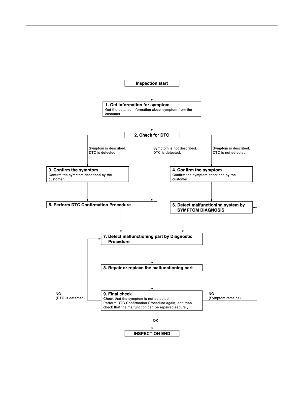
DIAGNOSIS AND REPAIR WORKFLOW
B
Revision: 2008 October 2009 Murano
< BASIC INSPECTION >
[WITH INTELLIGENT KEY SYSTEM]
BASIC INSPECTION
DIAGNOSIS AND REPAIR WORKFLOW
Work Flow INFOID:0000000003317971
OVERALL SEQUENCE
JMKIA3620G
DETAILED FLOW
DLK-14
Page 15

< BASIC INSPECTION >
Revision: 2008 October 2009 Murano
DIAGNOSIS AND REPAIR WORKFLOW
[WITH INTELLIGENT KEY SYSTEM]
1.GET INFORMATION FOR SYMPTOM
Get the detailed information from the customer about the symptom (the condition and the environment when
the incident/malfunction occurred).
>> GO TO 2.
2.CHECK FOR DTC
1. Check DTC for BCM and Automatic back door.
2. Perform the following procedure if DTC is displayed.
- Record DTC and freeze frame data (Print them out with CONSULT-III.)
- Erase DTC.
- Study the relationship between the cause detected by DTC and the symptom described by the customer.
3. Check related service bulletins for information.
Is any symptom described and any DTC detected?
Symptom is described, DTC is displayed>>GO TO 3.
Symptom is described, DTC is not displayed>>GO TO 4.
Symptom is not described, DTC is displayed>>GO TO 5.
3.CONFIRM THE SYMPTOM
Confirm the symptom described by the customer.
Connect CONSULT-III to the vehicle in “DATA MONITOR” mode and check real time diagnosis results.
Verify relation between the symptom and the condition when the symptom is detected.
>> GO TO 5.
4.CONFIRM THE SYMPTOM
A
B
C
D
E
F
G
H
Confirm the symptom described by the customer.
Connect CONSULT-III to the vehicle in “DATA MONITOR” mode and check real time diagnosis results.
Verify relation between the symptom and the condition when the symptom is detected.
>> GO TO 6.
5.PERFORM DTC CONFIRMATION PROCEDURE
Perform DTC Confirmation Procedure for the displayed DTC, and then check that DTC is detected again.
At this time, always connect CONSULT-III to the vehicle, and check diagnostic results in real time.
If two or more DTCs are detected, refer to DLK-254, "
"DTC Inspection Priority Chart" (automatic back door control unit) and determine trouble diagnosis order.
NOTE:
Perform Component Function Check if DTC Confirmation Procedure is not included in Service Manual. This
simplified check procedure is an effective alternative though DTC cannot be detected during this check.
If the result of Component Function Check is NG, it is the same as the detection of DTC by DTC Confirmation
Procedure.
Is DTC detected?
YES >> GO TO 7.
NO >> Refer to GI-40, "
Intermittent Incident".
DTC Inspection Priority Chart" (BCM) or DLK-268,
6.DETECT MALFUNCTIONING SYSTEM BY SYMPTOM DIAGNOSIS
Detect malfunctioning system according to SYMPTOM DIAGNOSIS based on the confirmed symptom in step
4, and determine the trouble diagnosis order based on possible causes and symptom.
>> GO TO 7.
7.DETECT MALFUNCTIONING PART BY DIAGNOSTIC PROCEDURE
I
J
DLK
L
M
N
O
P
Inspect according to Diagnostic Procedure of the system.
NOTE:
The Diagnostic Procedure described based on open circuit inspection. A short circuit inspection is also
required for the circuit check in the Diagnostic Procedure.
DLK-15
Page 16

DIAGNOSIS AND REPAIR WORKFLOW
Revision: 2008 October 2009 Murano
< BASIC INSPECTION >
Is malfunctioning part detected?
YES >> GO TO 8.
NO >> Check voltage of related BCM terminals using CONSULT-III.
[WITH INTELLIGENT KEY SYSTEM]
8.REPAIR OR REPLACE THE MALFUNCTIONING PART
1. Repair or replace the malfunctioning part.
2. Reconnect parts or connectors disconnected during Diagnostic Procedure again after repair and replacement.
3. Check DTC. If DTC is displayed, erase it.
>> GO TO 9.
9.FINAL CHECK
When DTC was detected in step 2, perform DTC Confirmation Procedure or Component Function Check
again, and then check that the malfunction has been repaired securely.
When symptom was described from the customer, refer to confirmed symptom in step 3 or 4, and check that
the symptom is not detected.
Does the symptom reappear?
YES (DTC is detected)>>GO TO 7.
YES (Symptom remains)>>GO TO 6.
NO >> INSPECTION END
DLK-16
Page 17

< BASIC INSPECTION >
Revision: 2008 October 2009 Murano
INSPECTION AND ADJUSTMENT
[WITH INTELLIGENT KEY SYSTEM]
INSPECTION AND ADJUSTMENT
ADDITIONAL SERVICE WHEN REMOVING BATTERY NEGATIVE TERMINAL
ADDITIONAL SERVICE WHEN REMOVING BATTERY NEGATIVE TERMINAL : Description
The automatic back door system must be initialized anytime the battery or the automatic back door control unit
has been disconnected.
INFOID:0000000003318304
ADDITIONAL SERVICE WHEN REMOVING BATTER Y NEGATIVE TERMINAL : S pecial Repair Requirement
INFOID:0000000003318305
1.INITIALIZATION
1. Close back door.
2. Open the back door with automatic open operation.
NOTE:
Do not stop the automatic operation until back door is fully open.
>> WORK END
ADDITIONAL SERVICE WHEN REPLACING CONTROL UNIT
ADDITIONAL SERVICE WHEN REPLACING CONTROL UNIT : Description
INFOID:0000000003317972
Perform the system initialization when replacing BCM, replacing Intelligent Key or registering an additional
Intelligent Key.
A
B
C
D
E
F
G
H
ADDITIONAL SERVICE WHEN REPLACING CONTROL UNIT : Special Repair Requirement INFOID:0000000003317973
Refer to the CONSULT-III operation manual for the initialization procedure.
I
J
DLK
L
M
N
O
P
DLK-17
Page 18
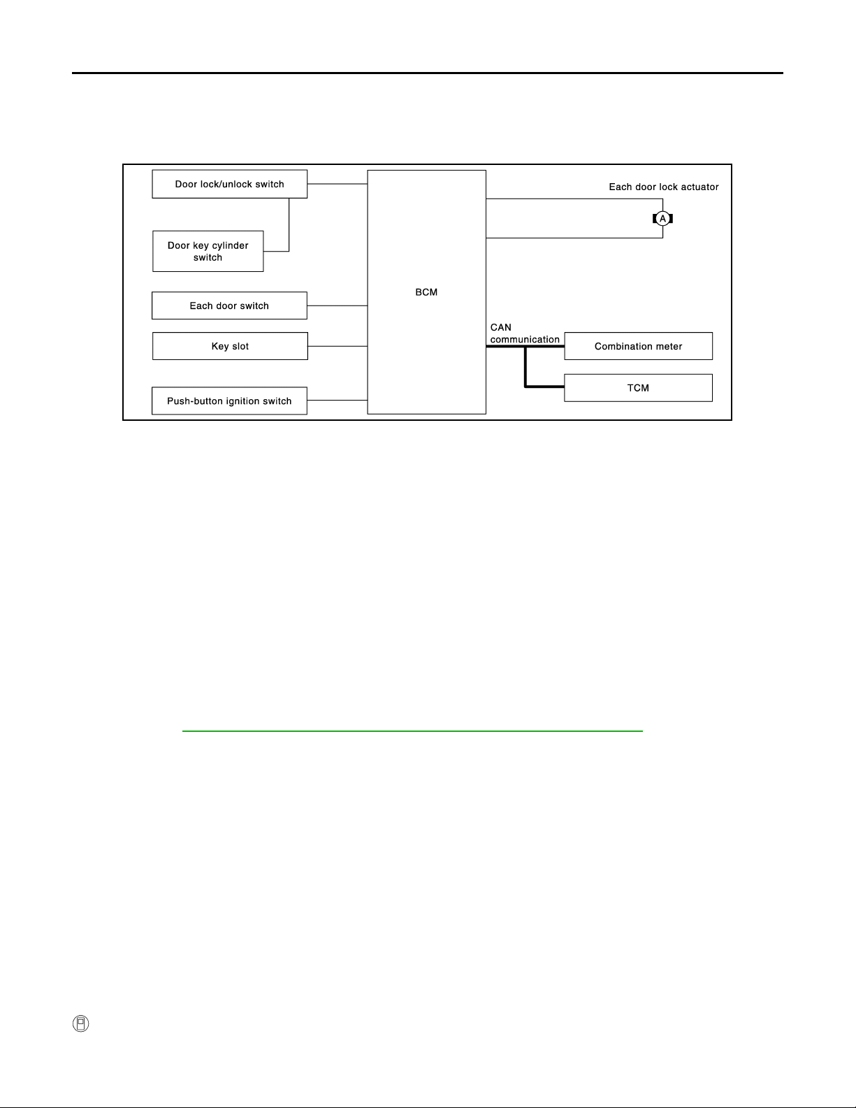
POWER DOOR LOCK SYSTEM
B
Revision: 2008 October 2009 Murano
< FUNCTION DIAGNOSIS >
[WITH INTELLIGENT KEY SYSTEM]
FUNCTION DIAGNOSIS
POWER DOOR LOCK SYSTEM
System Diagram INFOID:0000000003443643
JMKIA1991G
System Description INFOID:0000000003443644
DOOR LOCK FUNCTION
• The door lock and unlock switch (driver side) is build into power window main switch.
• The door lock and unlock switch (passenger side) is on door trim.
• Interlocked with the locking operation of door lock and unlock switch, door lock actuators of all doors are
locked.
• Interlocked with the unlocking operation of door lock and unlock switch, door lock actuators of all doors and
are unlocked.
Door Key Cylinder
• With the door key inserted in the door key cylinder on driver side, turning it to “LOCK”, will lock door lock
actuator of all doors.
• With the door key inserted in the door key cylinder on driver side, turning it to “UNLOCK” once unlocks the
driver side door lock actuator; turning it to “UNLOCK” again within 60 seconds after the first unlock operati on
unlocks all of the other doors. (SELECTIVE UNLOCK OPERATION)
Selective unlock operation mode can be changed using “DOOR LOCK-UNLOCK SET” mode in “WORK SUPPORT”. Refer to DLK-59, "
AUTOMATIC DOOR LOCK/UNLOCK FUNCTION (LOCK OPERATION)
The interlock door lock function is the function that locks all doors linked with the vehicle speed or shift position. It has 2 types as follows.
Vehicle Speed Sensing Auto Door Lock*1
All doors are locked when the vehicle speed reaches 15 miles or more.
BCM outputs the lock signal to all door lock actuators when it detects that the ignition switch is turned ON, all
doors are closed and the vehicle speed received from the combination meter via CAN communication
becomes 24 km/h (15 miles) or more.
DOOR LOCK : CONSULT-III Function (BCM - DOOR LOCK)".
P Range Interlock Door Lock
All doors are locked when shifting the selector lever from the P position to any position other than P.
BCM outputs the lock signal to all door lock actuators when it detects that the ignition switch is in the ON position and the shift signal received from the TCM via CAN communication is shifted from the P position to any
position other than P.
Setting change of Automatic Door Lock/Unlock Function
The lock operation setting of the automatic door lock/unlock function can be changed.
With CONSULT-III
The ON/OFF switching of the automatic door lock function and the type selection of the automatic door lock/
unlock function can be performed at the WORK SUPPORT setting of CONSULT-III.
DLK-18
Page 19

POWER DOOR LOCK SYSTEM
Revision: 2008 October 2009 Murano
< FUNCTION DIAGNOSIS >
Without CONSULT- III
The automatic door lock function ON/OFF can be switched by performing the following operation.
1. Close all doors (door switch OFF)
2. Turn ignition switch ON
3. Press and hold the door lock and unlock switch for 5 seconds or more in the lock direction within 20 seconds after turning the ignition switch ON.
4. The switching is completed when the hazard warning lamp blinks.
OFF → ON : 2 blinks
ON → OFF : 1 blink
AUTOMATIC DOOR LOCK/UNLOCK FUNCTION (UNLOCK OPERATION)
The automatic door lock/unlock function is the function that unlocks all doors linked with the key position or
shift position. It has 2 types as follows.
IGN OFF Interlock Door Unlock*1
All doors are unlocked when the power supply position is changed from ON to OFF.
BCM outputs the unlock signal to all door lock actuators when it detects that the power supply position is
changed from ignition switch ON to OFF.
P Range Interlock Door Unlock
All doors are unlocked when shifting the selector lever from any position other than the P to P position.
BCM outputs the unlock signal to all door lock actuators when it detects that the ignition switch is in the ON
position and the shift signal received from TCM via CAN communication is shif ted from any positi on other than
the P to P position.
Setting change of Automatic Door Lock/Unlock Function
The unlock operation setting of the automatic door lock/unlock function can be changed.
With CONSULT- III
The ON/OFF switching of the automatic door lock/unlock function and the type selection of the automatic door
lock/unlock function can be performed at the WORK SUPPORT setting of CONSULT-III.
Without CONSULT- III
The automatic door lock/unlock function ON/OFF can be switched by performing the following operation.
1. Close all doors below (door switch OFF)
2. Turn ignition switch ON
3. Press and hold the door lock and unlock switch for 5 seconds or more in the unlock direction within 20
seconds after turning the power supply position ON.
4. The switching is completed when the hazard warning lamp blinks.
[WITH INTELLIGENT KEY SYSTEM]
A
B
C
D
E
F
G
H
I
J
DLK
L
OFF → ON : 2 blinks
ON → OFF : 1 blink
*1: This function is set to ON before delivery.
DLK-19
M
N
O
P
Page 20
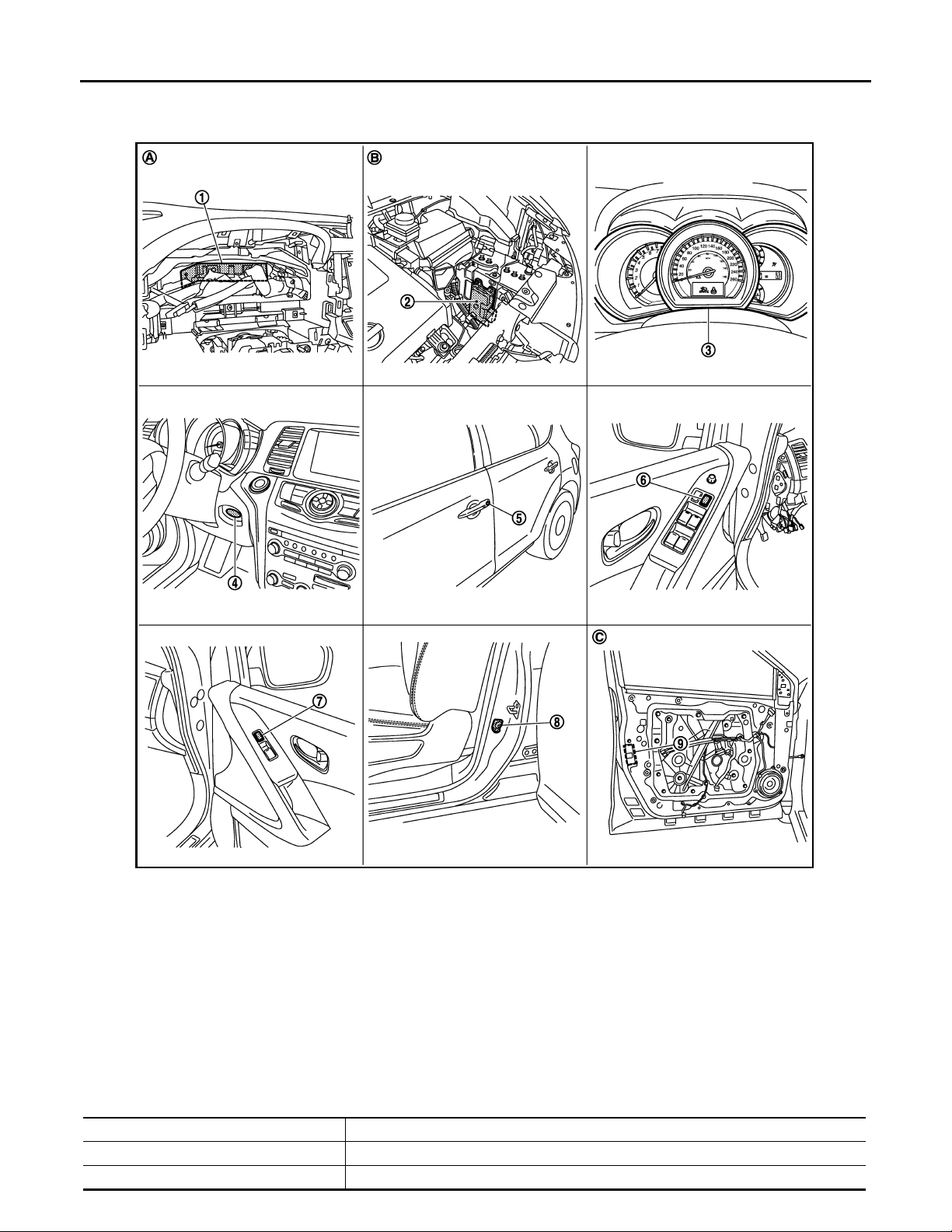
< FUNCTION DIAGNOSIS >
Revision: 2008 October 2009 Murano
POWER DOOR LOCK SYSTEM
[WITH INTELLIGENT KEY SYSTEM]
Component Parts Location
INFOID:0000000003443645
JMKIA1889ZZ
1. BCM M118, M119, M121, M122, M123 2. TCM F23 3. Combination meter M34
4. Key slot M99 5. Front door lock assembly (driver side)
(door key cylinder switch) D9
7. Front power window switch (passenger
side)
(door lock and unlock switch) D45
A. Behind the combination meter B. Engine room LH C. View with front door finisher re-
8. Front door switch (driver side) B34 9. Front door lock asse mb ly (drive r
6. Power window main switch
(door lock and unlock switch) D5,
D6
side) (door lock actuator) D9
moved
Component Description INFOID:0000000003443646
Item Function
BCM Controls the door lock function and room lamp function.
Door lock and unlock switch Input lock or unlock signal to BCM.
DLK-20
Page 21

< FUNCTION DIAGNOSIS >
Revision: 2008 October 2009 Murano
POWER DOOR LOCK SYSTEM
[WITH INTELLIGENT KEY SYSTEM]
Item Function
Door lock actuator Output lock/unlock signal from BCM and locks/unlocks each door.
Door switch Input door open/close condition t o BCM.
Door key cylinder switch
Key slot Input key insert/remove signal to BCM.
Combination meter
TCM Transmit shift position signal to BCM via CAN communication line.
Push-button ignition switch Input push-button ignition switch ON/OFF condition to BCM.
• Input lock or unlock signal to power window main switc h.
• Power window main switch transmits door lock/unlock signal to BCM.
• Receive buzzer signal from BCM via CAN communication line, and sounds the buzzer.
• Transmits vehicle speed signal to CAN communication line.
A
B
C
D
E
F
G
H
I
J
DLK
L
M
N
O
P
DLK-21
Page 22
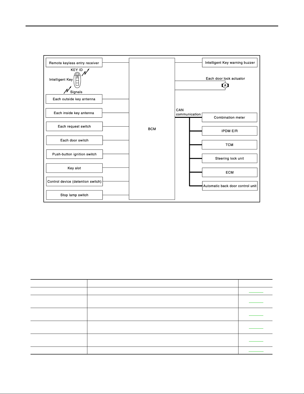
INTELLIGENT KEY SYSTEM
B
Revision: 2008 October 2009 Murano
< FUNCTION DIAGNOSIS >
[WITH INTELLIGENT KEY SYSTEM]
INTELLIGENT KEY SYSTEM
INTELLIGENT KEY SYSTEM
INTELLIGENT KEY SYSTEM : System Diagram INFOID:0000000003443675
JMKIA1992G
INTELLIGENT KEY SYSTEM : System Description INFOID:0000000003443676
• The Intelligent Key system is a system that makes it possible to lock and unlock the door locks (door lock/
unlock function) by carrying the Intelligent Key, which operates based on the results of electronic ID verification using two-way communications between the Intelligent Key and the vehicle (BCM).
CAUTION:
The driver should always carry the Intelligent Key
• The settings for each function can be changed with the CONSULT-III.
• If an Intelligent Key is lost, a new Intelligent Key can be registered. A maximum of 4 Intelligent Keys can be
registered.
• It is possible to perform a diagnosis on the system and register an Intelligent Key with the CONSULT-III.
Function Description Refer
Door lock function Lock/unlock can be performed by pressing the request switch. DLK-25
Remote keyless entry func-
tion
Back door open function
Key reminder function
Warning function
Engine start function The engine be turned on while carrying the Intelligent Key. SEC-12
Lock/unlock can be perfo rmed by pressin g the remote co ntroller but ton of the In telligent Key.
The back door can be opened by carrying the Intelligent Key and pressing the
back door opener switch.
The key reminder buzzer sounds a warning if the door is locked with the key left
inside the vehicle.
If an action that does not meet the operating condition of the Intelligent Key system is taken, the buzzer goes off to inform the driver.
DLK-34
DLK-30
DLK-39
DLK-41
DLK-22
Page 23
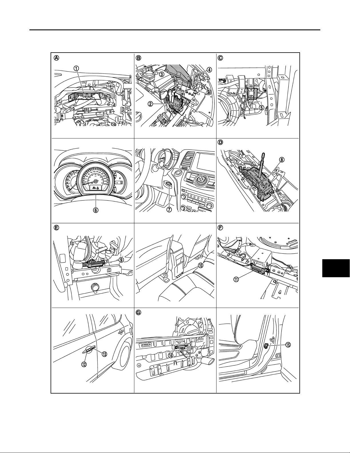
INTELLIGENT KEY SYSTEM
Revision: 2008 October 2009 Murano
< FUNCTION DIAGNOSIS >
[WITH INTELLIGENT KEY SYSTEM]
INTELLIGENT KEY SYSTEM : Component Parts Location INFOID:0000000003443677
A
B
C
D
E
F
G
H
I
J
DLK
L
M
N
O
JMKIA1932ZZ
1. BCM M118, M119, M120, M121, M122,
M123
4. IPDM E/R E10, E11 5. Remote keyless entry receiver M78 6. Combination meter M34
7. Key slot M99 8. Control device (detention switch) M57 9. Inside key antenna (instrument
2. TCM F23 3. Intelligent key warning buzzer E25
center) M105
DLK-23
P
Page 24
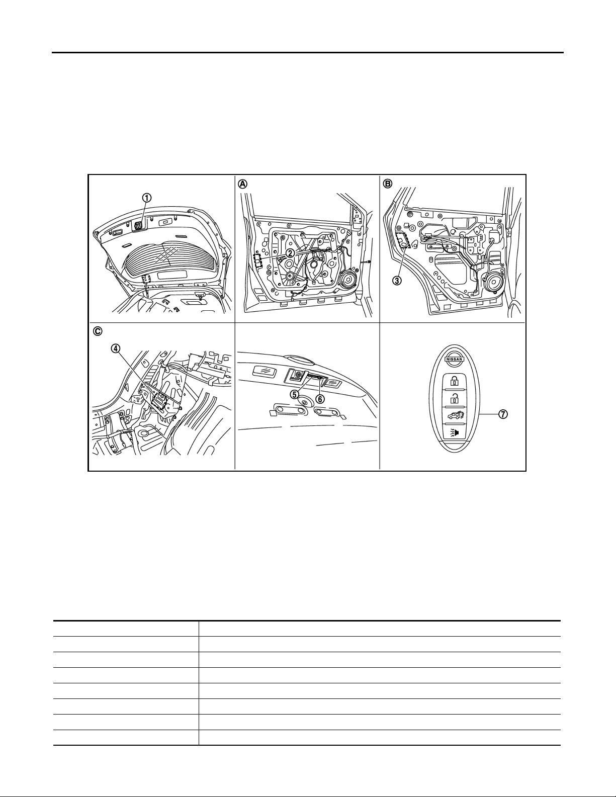
INTELLIGENT KEY SYSTEM
Revision: 2008 October 2009 Murano
< FUNCTION DIAGNOSIS >
10. Inside key antenna (console) M262 11. Inside key antenna (luggage room)
B86
13. Front outside handle LH (request s witch)
D11
A. Behind the combination meter B. Engine room (LH) C. Behind the instrument lower panel
D. Behind the center console E. Behind the cluster lid C assembly F. Under the rear seat seatback
G. View with rear bumper removed
14. Outside key antenna (rear bumper)
B85
[WITH INTELLIGENT KEY SYSTEM]
12. Front outside handle LH (outside
key antenna) D12
15. Front door switch (driver side) B34
RH
JMKIA1933ZZ
1. Back door lock assembly
With automatic back door: D179
Without automatic back door: D180
4. Automatic back door control unit B7, B8 5. Back door opener switch assembly (open-
7. Intelligent Key
A. View with front door finisher removed B. View with rear door finisher removed C. Behind the luggage side finisher
INTELLIGENT KEY SYSTEM : Component Description
Item Function
BCM Controls the Intelligent Key system.
Door lock actuator Output lock/unlock signal from BCM and locks/unlocks each door.
Door switch Input door open/close condition to BCM.
Remote keyless entry receiver Receives lock/unlock signal from the Intelligent Key, and then transmits to BCM.
Request switch Input lock/unlock operation to BCM.
Intelligent Key Transmits button operation to remote keyless entry receiver.
Outside key antenna Detects if Intelligent Key is outside the vehicle.
2. Front door lock assembly (driver side) D9 3. Rear door lock assembly LH D85
6. Back door opener switch assembly
er switch) D186
(request switch) D186
lower (LH)
INFOID:0000000003443678
DLK-24
Page 25
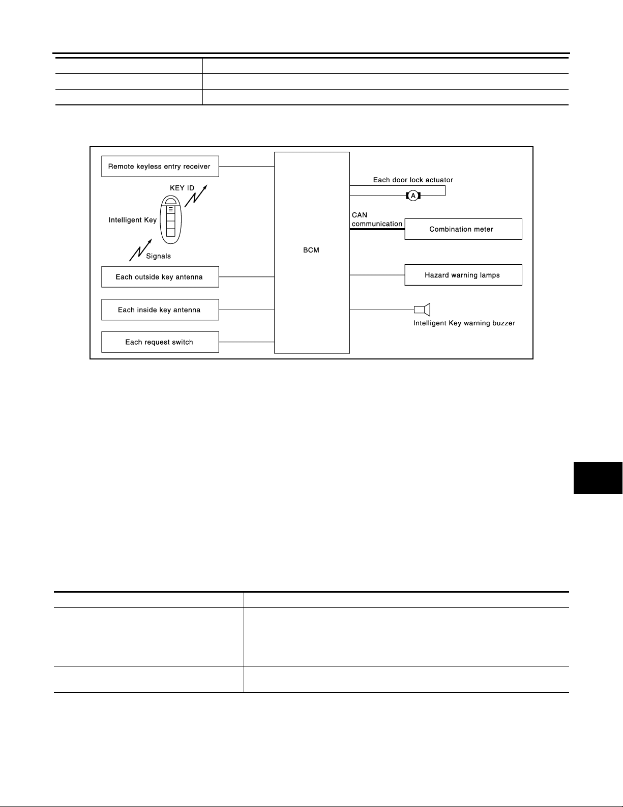
< FUNCTION DIAGNOSIS >
B
Revision: 2008 October 2009 Murano
INTELLIGENT KEY SYSTEM
[WITH INTELLIGENT KEY SYSTEM]
Item Function
Inside key antenna Detects if Intelligent Key is inside the vehicle.
Intelligent Key warning buzzer Warns the user of the lock/unlock condition and inappropriate operations with the buzzer sound.
DOOR LOCK FUNCTION
DOOR LOCK FUNCTION : System Diagram INFOID:0000000003443647
JMKIA1993G
A
B
C
D
E
F
G
H
DOOR LOCK FUNCTION : System Description INFOID:0000000003443648
Only when pressing the door request switch, it is possible to lock and unlock the door by carrying the Intelligent Key.
OPERATION DESCRIPTION
• When the BCM detects that each door request switch is pressed, it start s the outside key antenna and inside
key antenna corresponding to the pressed door request switch and transmits the request signal to the Intelligent Key. And then, check that the Intelligent Key is near the door.
• If the Intelligent Key is within the outside key antenna detection area, it receives the request signal and
transmits the key ID signal to the BCM via remote keyless entry receiver.
• BCM receives the key ID signal and compares it with the registered key ID.
• BCM lock/unlock each door (except back door) and sounds Intelligent Key buzzer warning (lock: 2 time,
unlock: 1 times) at the same time as a reminder.
OPERATION CONDITION
If the following conditions are satisfied, door lock/unlock operation is performed if the request switch is operated.
Each request switch operation Operation condition
• All doors are closed
• Ignition switch is in OFF position
Lock operation
Unlock Operation
*: Even with a registered Intelligent Key remaining inside the vehicle, door locks can be unlocked from outside of the vehicle with a spare
Intelligent Key as long as key IDs are different.
• Intelligent Key is out of key slo t
• Intelligent Key is outside the vehicle
• Intelligent Key is within outside key antenna detection area
• Intelligent Key is outside the vehicle
• Intelligent Key is within outside key antenna detection area *
I
J
DLK
L
M
N
O
P
OUTSIDE KEY ANTENNA DETECTION AREA
DLK-25
Page 26
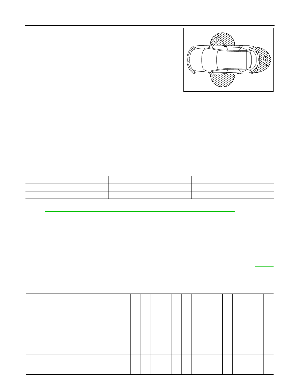
INTELLIGENT KEY SYSTEM
Revision: 2008 October 2009 Murano
< FUNCTION DIAGNOSIS >
The outside key antenna detection area of door lock/unlock function
is in the range of approximately 80 cm (31.50 in) surrounding the
driver, passenger door handles and (1) and the back door request
switch (2). However, this operating range depends on the ambient
conditions.
SELECTIVE UNLOCK FUNCTION
When an LOCK signal is sent from door request switch (driver side or passenger side), all doors will be locked.
When an UNLOCK signal is sent from door request switch (driver side or passenger side) once, driver's door
will be unlocked.
Then, if an UNLOCK signal is sent from door request switch (driver side and passenger side) again within 60
seconds, all other door will be unlocked.
HAZARD AND BUZZER REMINDER FUNCTION
During lock, unlock, operation by each request switch, the hazard warning lamps and Intelligent Key warning
buzzer will blink or honk as a reminder.
When doors are locked, unlocked by each request switch, BCM honks Intelligent Key warning buzzer as a
reminder and blinks.
[WITH INTELLIGENT KEY SYSTEM]
JMKIA1954ZZ
Operating Function of Hazard and Buzzer Reminder
Operation Hazard warning lamp blink Intelligent Key warning buzz er honk
Unlock Once Once
Lock Twice Twice
How to Change Hazard and Buzzer Reminder Mode
Refer to DLK-61, "INTELLIGENT KEY : CONSULT-III Function (BCM - INTELLIGENT KEY)".
AUTO DOOR LOCK FUNCTION
When all doors are locked, ignition switch is in OFF position and key switch is OFF (Intelligent Key is not
inserted in key slot), doors are unlocked with door request switch
When BCM does not receive the following signals within 60 seconds, all doors are locked.
• Door switch is ON (door is opened)
• Door is locked
• Ignition switch is ON (push-button ignition switch is pressed)
• Key switch is ON (Intelligent Key is inserted in key slot)
Auto door lock mode can be changed by “AUTO LOCK SET” mode in “WORK SUPPORT”. Refer to DLK-61,
"INTELLIGENT KEY : CONSULT-III Function (BCM - INTELLIGENT KEY)".
LIST OF OPERATION RELATED PARTS
Parts marked with × are the parts related to operation.
Door lock function
Intelligent Key
Key slot
Remote keyless entry receiver
Door switch
Door request switch
Door lock actuator
Inside key antenna
Outside key antenna
Intelligent Key warning buzzer
CAN communication system
BCM
Door lock/unlock function by door request switch ЧЧЧЧЧЧЧЧ ×
Hazard and buzzer reminder function for door lock/un-
lock operation
×××× ×
DLK-26
Hazard warning lamp
Push-button ignition switch
Combination meter
Page 27
< FUNCTION DIAGNOSIS >
Revision: 2008 October 2009 Murano
INTELLIGENT KEY SYSTEM
[WITH INTELLIGENT KEY SYSTEM]
A
Door lock function
Intelligent Key
Key slot
Remote keyless entry receiver
Door switch
Door request switch
Door lock actuator
Inside key antenna
Outside key antenna
Intelligent Key warning buzzer
CAN communication system
BCM
Hazard warning lamp
Push-button ignition switch
Combination meter
Key reminder function ЧЧЧЧЧЧЧЧЧ ××
Selective unlock function by request switch
(Driver side)
Selective unlock function by request switch
(Passenger side)
Selective unlock function b y requ est sw itch (b ack d oor) ×××××
Auto door lock function ×× ××× × ×
× ×××× ×
× ×××× ×
B
C
D
E
F
G
H
I
J
DLK
L
M
N
O
P
DLK-27
Page 28
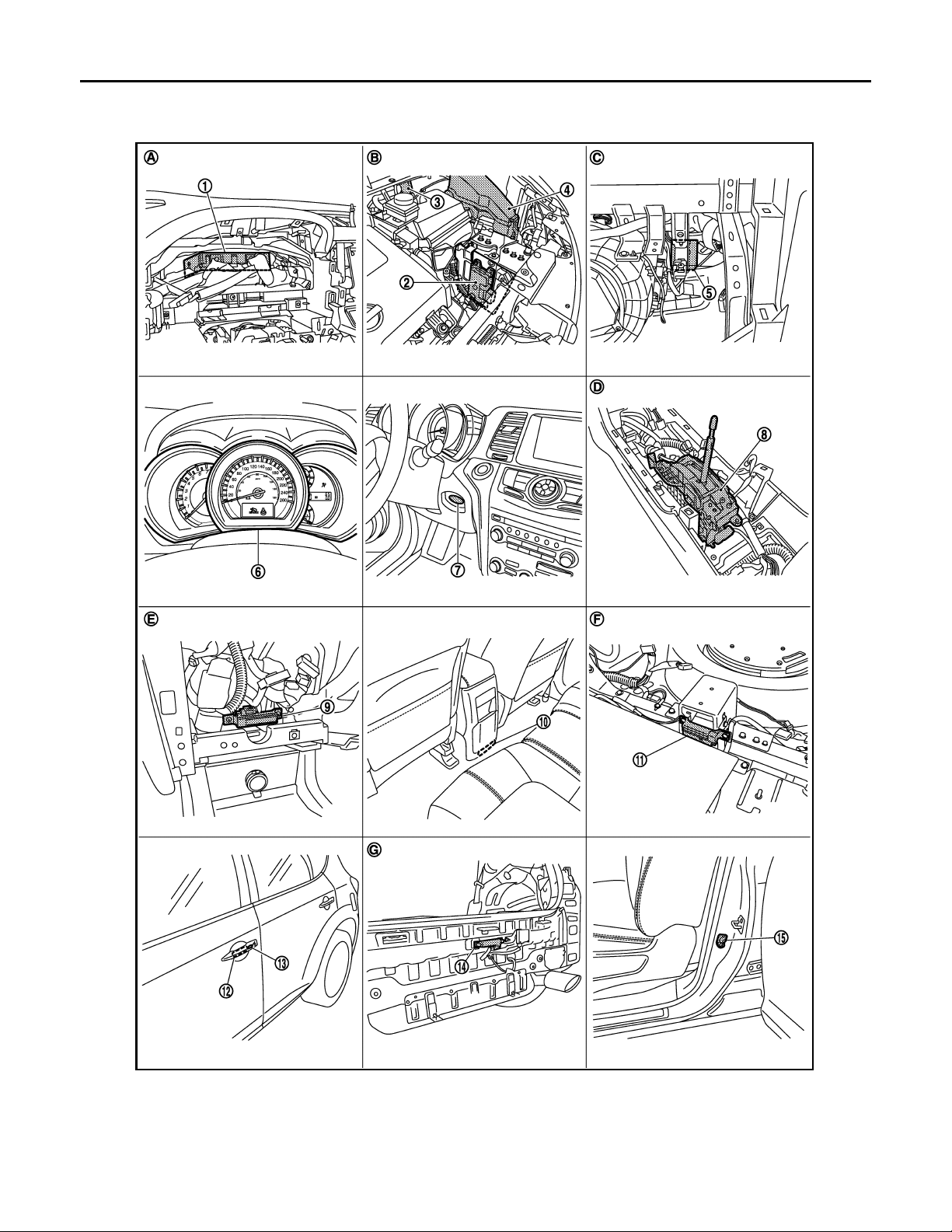
< FUNCTION DIAGNOSIS >
Revision: 2008 October 2009 Murano
INTELLIGENT KEY SYSTEM
[WITH INTELLIGENT KEY SYSTEM]
DOOR LOCK FUNCTION : Component Parts Location
INFOID:0000000003523740
JMKIA1932ZZ
1. BCM M118, M119, M120, M121, M122,
M123
4. IPDM E/R E10, E11 5. Remote keyless entry receiver M78 6. Combination meter M34
7. Key slot M99 8. Control device (detention switch) M57 9. Inside key antenna (instrument
2. TCM F23 3. Intelligent key warning buzzer E25
center) M105
DLK-28
Page 29
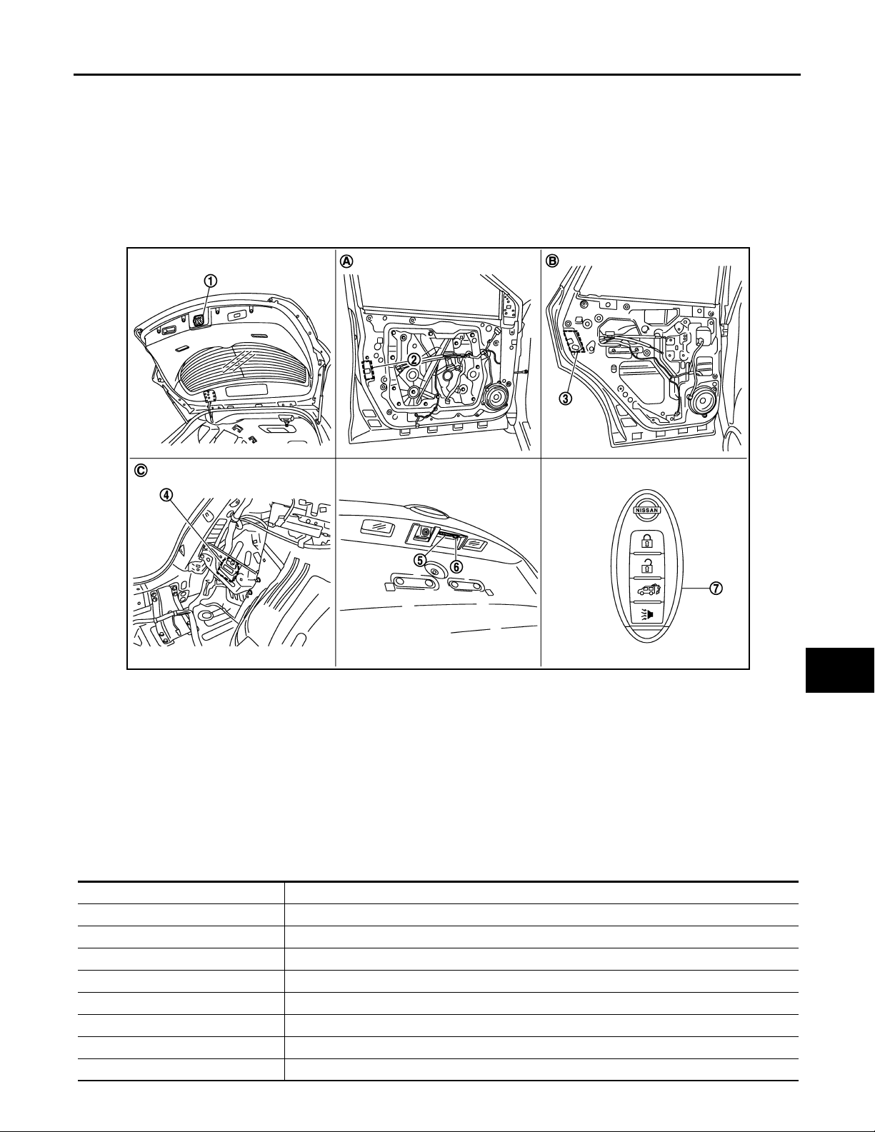
INTELLIGENT KEY SYSTEM
Revision: 2008 October 2009 Murano
< FUNCTION DIAGNOSIS >
10. Inside key antenna (console) M262 11. Inside key antenna (luggage room)
B86
13. Front outside handle LH (request switch)
D11
A. Behind the combination meter B. Engine room (LH) C. Behind the instrument lower panel
D. Behind the center console E. Behind the cluster lid C assembly F. Under the rear seat seatback
G. View with rear bumper removed
14. Outside key antenna (rear bumper)
B85
[WITH INTELLIGENT KEY SYSTEM]
12. Front outside handle LH (outside
key antenna) D12
15. Front door switch (driver side) B34
RH
A
B
C
D
E
F
G
JMKIA1933ZZ
1. Back door lock assembly
With automatic back door: D179
Without automatic back door: D180
4. Automatic back door control unit B7, B8 5. Back door opener switch assembly (open-
7. Intelligent Key
A. View with front door finisher removed B. View with rear door finisher removed C. Behind the luggage side finisher
2. Front door lock assembly (driver side) D9 3. Rear door lock assembly LH D85
6. Back door opener switch assembly
er switch) D186
(request switch) D186
lower (LH)
DOOR LOCK FUNCTION : Component Description INFOID:0000000003443650
Item Function
BCM Controls the door lock function.
Door lock actuator Output lock/unlock signal from BCM and locks/unlocks each door.
Door switch Input door open/close condition to BCM.
Remote keyless entry receiver Receives lock/unlock signal from the Intelligent Key, and then transmits to BCM.
Door request switch Input lock/unlock operation to BCM.
Intelligent Key Transmits button operation to remote keyless entry receiver.
Outside key antenna Detects if Intelligent Key is outside the vehicle.
Inside key antenna Detects if Intelligent Key is inside the vehicle.
H
I
J
DLK
L
M
N
O
P
DLK-29
Page 30
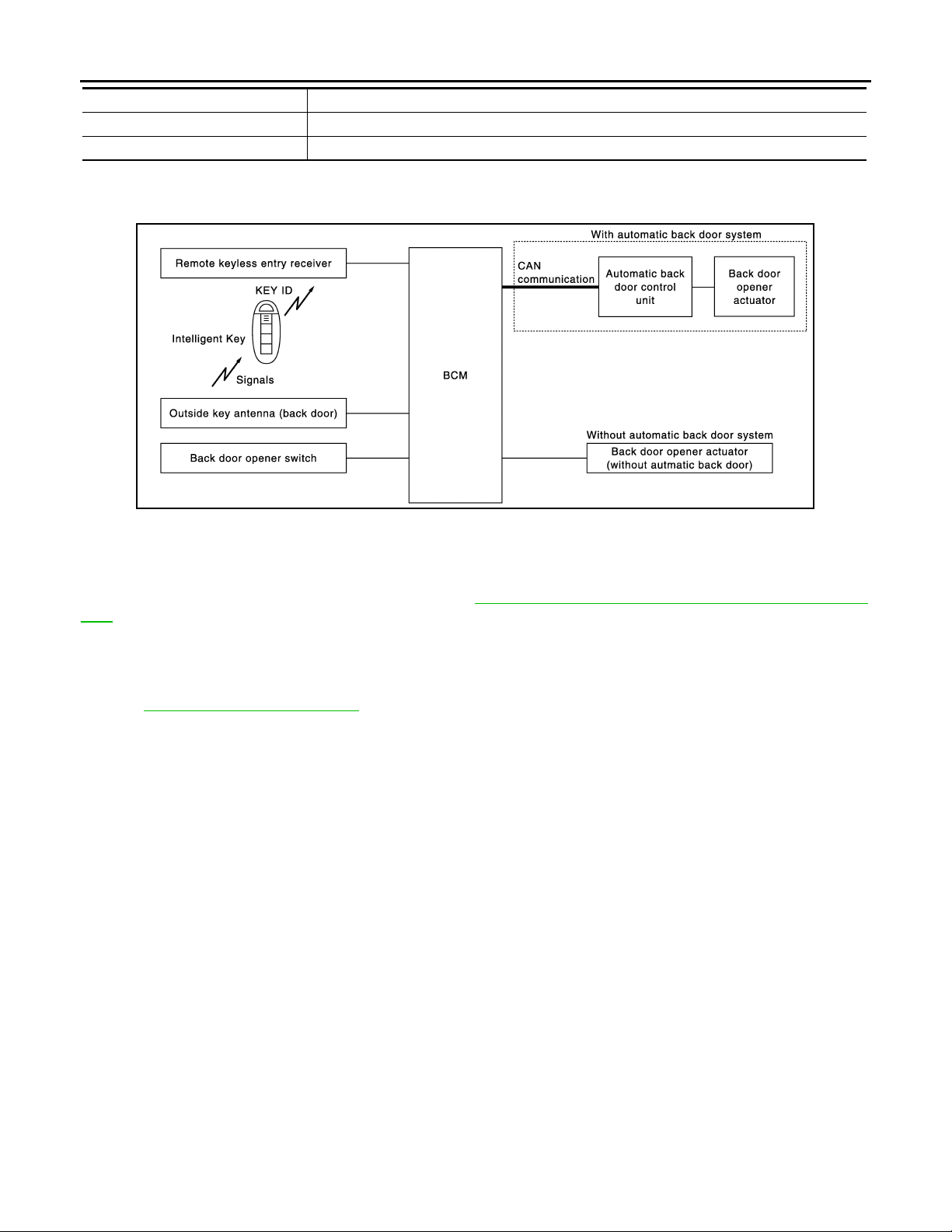
INTELLIGENT KEY SYSTEM
B
Revision: 2008 October 2009 Murano
< FUNCTION DIAGNOSIS >
Item Function
Combination meter Receives hazard warning lamp signal from BCM and blinks turn signal indicators.
Intelligent Key warning buzzer Warns the user of the lock/u nlock condition and inap propriate operations with th e buzzer sound.
[WITH INTELLIGENT KEY SYSTEM]
BACK DOOR OPEN FUNCTION
BACK DOOR OPEN FUNCTION : System Diagram INFOID:0000000003497494
JMKIA1994G
BACK DOOR OPEN FUNCTION : System Description INFOID:0000000003497495
This section describes the operation of the back door opener switch. The operation of the back door request
switch is the same as the door lock function. Refer to DLK-25, "
tion".
• The back door opener function can open the back door by pressing the back door opener switch whi le carrying the Intelligent Key. At this time, all doors other than the back door are locked.
• The back door opener function can open the back door by pressing the back door opener switch with all
doors unlocked by the door request switch or Intelligent Key.
Refer to DLK-48, "
System Description" for the automatic back door operation.
BACK DOOR OPEN
• When the BCM detects that back door opener switch is pressed, it starts the outside key antenna (back
door) and inside key antenna and transmits the request signal to the Intelligent Key. And then, check that the
Intelligent Key is near the back door.
• If the Intelligent Key is within the outside key antenna detection area, it receives the request signal and
transmits the key ID signal to the BCM via remote keyless entry receiver.
• BCM receives the key ID signal and compares it with the registered key ID.
• BCM open the back door and sounds Intelligent Key buzzer warning at the same time as a reminder.
OPERATION CONDITION
If the following conditions are satisfied, the back door can be opened.
• Back door is closed
• Ignition switch is in off position
• Intelligent Key is out of key slot
• Intelligent Key is outside of vehicle
• Intelligent Key is within out side key antenna detection area
DOOR LOCK FUNCTION : System Descrip-
OUTSIDE KEY ANTENNA DETECTION AREA
DLK-30
Page 31

INTELLIGENT KEY SYSTEM
Revision: 2008 October 2009 Murano
< FUNCTION DIAGNOSIS >
The outside key antenna detection area of back door open function
is in the range of approximately 80 cm (31.50 in) surrounding the
back door opener switch (1). However , this operating range depends
on the ambient conditions.
HAZARD AND BUZZER REMINDER FUNCTION
Back door opening operation by back door opener switch, the hazard warning lamps and buzzer will blink or
honk as a reminder.
LIST OF OPERATION RELATED PARTS
Parts marked with × are the parts related to operation.
[WITH INTELLIGENT KEY SYSTEM]
JMKIA1955ZZ
A
B
C
D
E
F
G
Door lock function
Back door open function by back door opener switch
(Carrying Intelligent Key)
Hazard and buzzer reminder function for do or lock/unlock
operation
Intelligent Key
Key slot
Remote keyless entry receiver
Door switch
Door request switch
Door lock actuator
Inside key antenna
Outside key antenna (Rear bumper)
Intelligent Key warning buzzer
CAN communication system
BCM
Hazard warning lamp
Back door opener switch
ЧЧЧЧЧЧЧЧ ×× ×
××××
H
I
J
DLK
L
M
N
O
DLK-31
P
Page 32

< FUNCTION DIAGNOSIS >
Revision: 2008 October 2009 Murano
INTELLIGENT KEY SYSTEM
[WITH INTELLIGENT KEY SYSTEM]
BACK DOOR OPEN FUNCTION : Component Parts Location
INFOID:0000000003523741
JMKIA1932ZZ
1. BCM M118, M119, M120, M121, M122,
M123
4. IPDM E/R E10, E11 5. Remote keyless entry receiver M78 6. Combination meter M34
7. Key slot M99 8. Control device (detention switch) M57 9. Inside key antenna (instrument
2. TCM F23 3. Intelligent key warning buzzer E25
center) M105
DLK-32
Page 33

INTELLIGENT KEY SYSTEM
Revision: 2008 October 2009 Murano
< FUNCTION DIAGNOSIS >
10. Inside key antenna (console) M262 11. Inside key antenna (luggage room)
B86
13. Front outside handle LH (request switch)
D11
A. Behind the combination meter B. Engine room (LH) C. Behind the instrument lower panel
D. Behind the center console E. Behind the cluster lid C assembly F. Under the rear seat seatback
G. View with rear bumper removed
14. Outside key antenna (rear bumper)
B85
[WITH INTELLIGENT KEY SYSTEM]
12. Front outside handle LH (outside
key antenna) D12
15. Front door switch (driver side) B34
RH
A
B
C
D
E
F
G
JMKIA1933ZZ
1. Back door lock assembly
With automatic back door: D179
Without automatic back door: D180
4. Automatic back door control unit B7, B8 5. Back door opener switch assembly (open-
7. Intelligent Key
A. View with front door finisher removed B. View with rear door finisher removed C. Behind the luggage side finisher
2. Front door lock assembly (driver side) D9 3. Rear door lock assembly LH D85
6. Back door opener switch assembly
er switch) D186
(request switch) D186
lower (LH)
BACK DOOR OPEN FUNCTION : Component Description INFOID:0000000003497497
Item Function
BCM Controls the back door open function and room lamp function.
Back door opener switch Input press/degrees signal to BCM.
Door lock actuator Receives lock/unlock signal from BCM and locks/unlocks each door.
Door switch Input door open/close condition to BCM.
Remote keyless entry receiver Receives lock/unlock signal from the Intelligent Key, and then transmits to BCM.
Request switch (back door) Input lock/unlock operation to BCM.
Intelligent Key Transmits button operation to remote keyless entry receiver.
Outside key antenna (rear bumper) Detects if Intelligent Key is outside the vehicle.
H
I
J
DLK
L
M
N
O
P
DLK-33
Page 34

INTELLIGENT KEY SYSTEM
B
Revision: 2008 October 2009 Murano
< FUNCTION DIAGNOSIS >
Item Function
Inside key antenna Detects if Intelligent Key is inside the vehicle.
Intelligent Key warning buzzer
Automatic back door control unit Controls back door open/close automatically.
Warns the user of the back door open/close condition and inappropriate operations with the
buzzer sound.
[WITH INTELLIGENT KEY SYSTEM]
REMOTE KEYLESS ENTRY FUNCTION
REMOTE KEYLESS ENTRY FUNCTION : System Diagram INFOID:0000000003443651
JMKIA1995G
REMOTE KEYLESS ENTRY FUNCTION : System Description INFOID:0000000003443652
The Intelligent Key has the same functions as the remote control entry system. Therefore, it can be used in the
same manner as the Intelligent Ke by operating the door lock/unlock button.
OPERATION
Remote keyless entry system controls operation of the
• Door lock/unlock
• Automatic back door open
• Selective unlock
• Hazard and horn reminder
• Auto door lock
• Panic alarm
• Power window down
OPERATION AREA
To ensure the Intelligent Key works effectively, use within 1 m (3 ft) range of each doors, however the operable
range may differ according to surroundings.
DOOR LOCK/UNLOCK FUNCTION
• When door lock/unlock button of the Intelligent Key is pressed, lock signal or unlock signal is transmits from
Intelligent Key to BCM via remote keyless entry receiver.
• When BCM receives the door lock/unlock signal, it operates door lock actuator, flashes the hazard warning
lamp (lock: 2 time, unlock: 1 times) and horn chirp signal to IPDM E/R at the same time as a reminder.
• IPDM E/R honks horn (lock: 2 time) as a reminder
OPERATION CONDITION
Remote controller operation Operation condition Operation
Lock • All doors closed All doors lock
Unlock • Intelligent Key is out of key slot All doors unlock
DLK-34
Page 35

INTELLIGENT KEY SYSTEM
B
Revision: 2008 October 2009 Murano
< FUNCTION DIAGNOSIS >
AUTOMATIC BACK DOOR OPEN FUNCTION
When back door button of Intelligent Key is pressed for more than 1 second, back door open automatically for
detailed description, refer to DLK-48, "
System Description".
[WITH INTELLIGENT KEY SYSTEM]
A
SELECTIVE UNLOCK FUNCTION
When an LOCK signal is transmitted from Intelligent Key, all doors will be locked.
When an UNLOCK signal is transmitted from Intelligent Key once, driver's door will be unlocked.
Then, if an UNLOCK signal is transmitted from Intelligent Key again within 60 seconds, all other door will be
unlocked.
HAZARD AND HORN REMINDER FUNCTION
When doors are locked or unlocked by Intelligent Key, BCM flashes hazard warning lamps as a reminder.
The hazard and horn reminder has a horn chirp mode (C mode) and a non-horn chirp mode (S mode).
Operating Function of Hazard and Horn Reminder
C mode S mode
Intelligent Key operation Lock Unlock Lock Unlock
Hazard warning lamp blink Twice Once Twice —
Horn sound Once — — —
Hazard and horn reminder does not operate if any door switch is ON (any door is OPEN).
How to Change Hazard and Horn Reminder Mode
With CONSULT-III
Refer to DLK-61, "
Without CONSULT-III
When LOCK and UNLOCK signals are sent from the Intelligent Key for more than 2 seconds at the same time,
the hazard and horn reminder mode is changed and hazard warning lamp blinks and horn sounds as follows:
INTELLIGENT KEY : CONSULT-III Function (BCM - INTELLIGENT KEY)".
B
C
D
E
F
G
H
I
JMKIA2755G
AUTO DOOR LOCK FUNCTION
When all doors are locked, ignition switch is OFF (ignition switch is not pressed) and key switch is OFF (Intelligent Key is not inserted in key slot), doors are unlocked with Intelligent Key button. When BCM does not
receive the following signals within 30 seconds, all doors are locked.
• Door switch is ON (door is opened)
• Door is locked
• Ignition switch is ON
• Key switch is ON (Intelligent Key is inserted in key slot)
Auto door lock mode can be changed by “AUTO LOCK SET” mode in “WORK SUPPORT”. Refer to DLK-61,
"INTELLIGENT KEY : CONSULT-III Functi on (BCM - INTELLIGENT KEY)".
PANIC ALARM FUNCTION
When ignition switch is OFF (ignition switch is not pressed) and key switch is OFF (Intelligent Key is not
inserted in key slot), BCM receives PANIC ALARM signal from Intelligent Key.
BCM turns on and off headlamp intermittently and transmits theft warning horn signal to IPDM E/R. Then,
IPDM E/R turns on and off horn intermittently.
The headlamp blinks and the horn sounds intermittently.
The alarm automatically turns off:
• After 25 seconds
• When BCM receives any signal from Intelligent Key
Panic alarm function mode can be changed by “PANIC ALARM SET” mode in “WORK SUPPORT”. Refer to
DLK-61, "
INTELLIGENT KEY : CONSULT-III Function (BCM - INTELLIGENT KEY)".
J
DLK
L
M
N
O
P
DLK-35
Page 36

INTELLIGENT KEY SYSTEM
Revision: 2008 October 2009 Murano
< FUNCTION DIAGNOSIS >
KEYLESS POWER WINDOW DOWN (OPEN) FUNCTION
All power windows open when the unlock button on Intelligent Key is activated and kept pressed for more than
3 seconds with the ignition switch OFF. The windows keep opening if the unlock button is continuously
pressed.
The power window opening stops when the following operations are performed:
• When the unlock button is kept pressed more than 15 seconds.
• When the ignition switch is turned ON while the power window opening is operated.
• When the unlock button is released.
While retained power operation activate, Keyless power window down (open) function cannot be operated.
Keyless power window down operation mode can be changed by “PW DOWN SET” mode in “WORK SUPPORT”. Refer to DLK-61, "
INTELLIGENT KEY : CONSULT-III Function (BCM - INTELLIGENT KEY)".
LIST OF OPERATION RELATED PARTS
Parts marked with × are the parts related to operation.
Remote keyless entry functions
[WITH INTELLIGENT KEY SYSTEM]
Intelligent Key
Key slot
Door request switch
Door switch
Door lock actuator
CAN communication system
BCM
Combination meter
Hazard warning lamp
Horn
IPDM E/R
Head lamp
Power window switch
Door lock/unlock function by remote control button ×× ×× ×
Hazard and horn reminder function × ЧЧЧЧЧЧ
Selective unlock function ××××
Keyless power window down (open) function ×× × ×
Auto door lock function ×× × ×
Panic alarm function × × ×× ×××
DLK-36
Page 37

INTELLIGENT KEY SYSTEM
Revision: 2008 October 2009 Murano
< FUNCTION DIAGNOSIS >
[WITH INTELLIGENT KEY SYSTEM]
REMOTE KEYLESS ENTRY FUNCTION : Component Parts Location INFOID:0000000003523742
A
B
C
D
E
F
G
H
I
J
DLK
L
M
N
O
JMKIA1932ZZ
1. BCM M118, M119, M120, M121, M122,
M123
4. IPDM E/R E10, E11 5. Remote keyless entry receiver M78 6. Combination meter M34
7. Key slot M99 8. Control device (detention switch) M57 9. Inside key antenna (instrument
2. TCM F23 3. Intelligent key warning buzzer E25
center) M105
DLK-37
P
Page 38

INTELLIGENT KEY SYSTEM
Revision: 2008 October 2009 Murano
< FUNCTION DIAGNOSIS >
10. Inside key antenna (console) M262 11. Inside key antenna (luggage room)
B86
13. Front outside handle LH (request s witch)
D11
A. Behind the combination meter B. Engine room (LH) C. Behind the instrument lower panel
D. Behind the center console E. Behind the cluster lid C assembly F. Under the rear seat seatback
G. View with rear bumper removed
14. Outside key antenna (rear bumper)
B85
[WITH INTELLIGENT KEY SYSTEM]
12. Front outside handle LH (outside
key antenna) D12
15. Front door switch (driver side) B34
RH
JMKIA1933ZZ
1. Back door lock assembly
With automatic back door: D179
Without automatic back door: D180
4. Automatic back door control unit B7, B8 5. Back door opener switch assembly (open-
7. Intelligent Key
A. View with front door finisher removed B. View with rear door finisher removed C. Behind the luggage side finisher
REMOTE KEYLESS ENTRY FUNCTION : Component Description
Item Function
BCM Controls the door lock function and room lamp function.
Door lock actuator Outputs lock/unlock signal from BCM and locks/unlocks each door.
Remote keyless entry receiver Receives lock/unlock signal from the Intelligent Key, and then transmits to BCM.
Intelligent Key Transmits button operation to remote keyless entry receiver.
2. Front door lock assembly (driver side) D9 3. Rear door lock assembly LH D85
6. Back door opener switch assembly
er switch) D186
(request switch) D186
lower (LH)
INFOID:0000000003443654
KEY REMINDER FUNCTION
DLK-38
Page 39

INTELLIGENT KEY SYSTEM
B
Revision: 2008 October 2009 Murano
< FUNCTION DIAGNOSIS >
[WITH INTELLIGENT KEY SYSTEM]
KEY REMINDER FUNCTION : System Description INFOID:0000000003443669
JMKIA1996G
Key reminder is the function that prevents the key from being left in the vehicle.
Key reminder has the following 3 functions.
Key remainder function Operation condition Operation
Right after driver side door is cl osed under the following conditions
Driver door closed*
Door is open or closed
Back door is closed
*:If the door closing impact shocks the door lock knob, or contacts against baggage with the door lock knob might activate the door locks
accidentally but unlock operation will be perform in these cases.
• Door lock operation is performed
• Driver side door is opened
• Driver side door is in lock state
Right after all doors are closed under the following conditions
• Intelligent Key is inside the vehicle
• Any door is opened
• All doors are locked by door lock and unlock switch or door lock knob
Right after back door is closed under the following conditions
• Intelligent Key is inside vehicle
• All doors (except back door) are closed
• All doors (except back door) are locked
CAUTION:
• The above function operates when the Intelligent Key is inside the vehicle. However, there may be
times when the Intelligent Key cannot be detected, and this function will not operate when the Intelligent Key is on the instrument panel, or in the glove box. Also, this system sometimes does not operate if the Intelligent Key is in the door pocket for the open door.
• Key reminder function is operated when the back door is open/closed and the buzzers sound, if the
following operations are performed, the key reminder function is cleared and buzzer sounds are
stopped.
- Remote controller door lock button operation of Intelligent Key
- Remote controller door unlock button operation of Intelligent Key
- When the back door is closed, the Intelligent Key is not inside the vehicle
- When any door is open
All doors unlock
• All doors unlock
• Honk Intelligent Key warning
buzzer
• All doors unlock
• Back door can open with
back door opener switch
• Honk Intelligent Key warning
buzzer
A
B
C
D
E
F
G
H
I
J
DLK
L
M
N
DLK-39
O
P
Page 40

< FUNCTION DIAGNOSIS >
Revision: 2008 October 2009 Murano
INTELLIGENT KEY SYSTEM
[WITH INTELLIGENT KEY SYSTEM]
KEY REMINDER FUNCTION : Component Parts Location
INFOID:0000000003523750
JMKIA1932ZZ
1. BCM M118, M119, M120, M121, M122,
M123
4. IPDM E/R E10, E11 5. Remote keyless entry receiver M78 6. Combination meter M34
7. Key slot M99 8. Control device (detention switch) M57 9. Inside key antenna (instrument
2. TCM F23 3. Intelligent key warning buzzer E25
center) M105
DLK-40
Page 41

INTELLIGENT KEY SYSTEM
Revision: 2008 October 2009 Murano
< FUNCTION DIAGNOSIS >
10. Inside key antenna (console) M262 11. Inside key antenna (luggage room)
B86
13. Front outside handle LH (request switch)
D11
A. Behind the combination meter B. Engine room (LH) C. Behind the instrument lower panel
D. Behind the center console E. Behind the cluster lid C assembly F. Under the rear seat seatback
G. View with rear bumper removed
14. Outside key antenna (rear bumper)
B85
[WITH INTELLIGENT KEY SYSTEM]
12. Front outside handle LH (outside
key antenna) D12
15. Front door switch (driver side) B34
RH
A
B
C
D
E
F
G
JMKIA1933ZZ
1. Back door lock assembly
With automatic back door: D179
Without automatic back door: D180
4. Automatic back door control unit B7, B8 5. Back door opener switch assembly (open-
7. Intelligent Key
A. View with front door finisher removed B. View with rear door finisher removed C. Behind the luggage side finisher
2. Front door lock assembly (driver side) D9 3. Rear door lock assembly LH D85
6. Back door opener switch assembly
er switch) D186
(request switch) D186
lower (LH)
WARNING FUNCTION
WARNING FUNCTION : System Description INFOID:0000000003443667
OPERATION DESCRIPTION
The warning function are as follows and are given to the user as warning information and warnings using combinations of Intelligent Key warning buzzer, KEY warning lamp, key slot illumination and information display in
combination meter.
• Intelligent Key system malfunction
• OFF position warning
• P position warning
• ACC warning
• Take away warning
• Door lock operation warning
• Key warning
H
I
J
DLK
L
M
N
O
P
DLK-41
Page 42

INTELLIGENT KEY SYSTEM
Revision: 2008 October 2009 Murano
< FUNCTION DIAGNOSIS >
• Intelligent Key insert information
• Engine start information
• Steering lock information
• Intelligent key low battery warning
• Key ID warning
OPERATION CONDITION
Once the following condition from below is established, alert or warning will be executed.
Warning/Information functions Operation procedure
Intelligent Key system malfunction When a malfunction is detected on BCM, “KEY” warning lamp will illuminate.
For internal
OFF position warning
For external
P position warning
ACC warning
Door is open to close
Door is open
Push button-ignition
Take away warning
Door lock operation warning
Key warning
Intelligent Key insert information
switch operation
Take away through window
Intelligent Key is removed
from key slot
Request switch operation
Intelligent Key button operation
• Ignition switch: ACC position.
• Door switch (driver side): ON (Door is open).
OFF position warning (For internal) is in active mode, driver side door has
been closed.
NOTE:
OFF position (For external) active only when each of the sequence has occurred as below: P position warning → ACC warning → OFF position warning
(For internal) → OFF position warning (For internal)
• Shift position: Except P position.
• Engine is running to stopped (Ignition switch is ON to OFF).
• During P position warning is in active mode, shift position has changed P position.
• Ignition switch: ACC position.
• Ignition switch: Except LOCK position.
• Door switch: ON to OFF (Door is open to close).
• Intelligent Key can not be detected inside t he vehicle.
• Door switch: ON (Door is open).
• Key ID verification every 5 seconds when regi stered I ntelli gent Key c an not
be detected inside the vehi cle.
• Ignition switch: Except LOCK position.
• Press push-button ignition switch.
• Intelligent Key can not be detected inside t he vehicle.
• Engine is running.
• Key ID verification every 30 seconds when registered Intelligent Key can not
be detected inside the vehi cle.
• After vehicle speed verification, the registered Intelligent Key can not be detect inside the vehicle.
• When Intelligent Key is removed from key slot, Intelligent Key can not be detected inside the vehicle.
When request switch is pushed (lock opera tion) under the following cond itions.
• All door is closed.
• All door is unlocked.
• Intelligent Key is inside vehicle.
When Intelligent Key button is pushed (lock operation) under the following conditions.
• Door switch: ON (Any door is open).
• For 3 seconds after Intelligent Key is removed from key slot.
• Ignition switch is OFF position.
• Driver side door switch: ON (Driver side door is op en).
• Intelligent Key is inserted in key slot.
• Door switch: ON to OFF (Door is open to close).
• Ignition switch: OFF to ON position.
• Intelligent Key is out of key slot.
• Intelligent Key can not be detected inside t he vehicle.
[WITH INTELLIGENT KEY SYSTEM]
DLK-42
Page 43

< FUNCTION DIAGNOSIS >
B
B
B
Revision: 2008 October 2009 Murano
INTELLIGENT KEY SYSTEM
[WITH INTELLIGENT KEY SYSTEM]
Warning/Information functions Operation procedure
Ignition switch is ON position
Engine start information
Ignition switch is except
ON position
Steering lo ck information When steering lock can not be re leased after ignition switch is t urned ON.
Intelligent Key low battery warning
Key ID warning
• Ignition switch: ON position.
• Shift position: P position.
• Engine is stopped .
• Ignition switch: Except ON position.
• Shift position: P position.
• Intelligent Key is inserted in key slot or Intelligent Key can be detected inside
the vehicle.
When Intelligent Key is low battery, BCM is detected after ignition switch is
turned ON.
When registered intelligent Key can not be detected inside the vehicle after ignition switch is turned ON.
WARNING METHOD
The following table shows the alarm or warning methods with chime.
Information display (combination meter), “KEY” indicator or key slot illumination when the warning conditions
are met.
Warning chime
Warning/Information functions
Intelligent Key system malfunction Illuminate — — — —
OFF position warn-
ing
For internal — — — Activate —
For external — — — — Activate
“KEY” warn-
ing lamp
Information display
(combination meter)
Key slot illumination
Combination
meter buzzer
Intelligent
Key warning
buzzer
A
B
C
D
E
F
G
H
I
P position warning — — Activate —
JMKIA0037G
ACC warning — — — —
JMKIA0047G
Take away warning
Door lock operation
warning
Door is open to
close
Door is open — Flash — —
Push-ignition
switch operation
Take away
through window
Intelligent Key is
removed from
key slot
Request switch
operation
Intelligent Key
operation
— Blink Activate Activate
—FlashActivate—
—FlashActivate—
—Flash——
————Activate
————Activate
JMKIA0036G
J
DLK
L
M
N
O
P
DLK-43
Page 44

INTELLIGENT KEY SYSTEM
B
B
B
B
B
B
Revision: 2008 October 2009 Murano
< FUNCTION DIAGNOSIS >
Warning/Information functions
“KEY” warn-
ing lamp
Key ID warning — — — —
Key warning — Flash Activate —
Information display
(combination meter)
[WITH INTELLIGENT KEY SYSTEM]
Warning chime
Key slot illumination
JMKIA0036G
JMKIA0035G
Combination
meter buzzer
Key warning
Intelligent
buzzer
Intelligent Key insert information — Flash — —
JMKIA0034G
Engine start information — — — —
JMKIA0032G
Steering lock information — — — —
JMKIA0033G
Intelligent Key low battery warning — — — —
JMKIA0048G
LIST OF OPERATION RELATED PARTS
Parts marked with × are the parts related to operation.
DLK-44
Page 45

< FUNCTION DIAGNOSIS >
Revision: 2008 October 2009 Murano
Warning function
INTELLIGENT KEY SYSTEM
[WITH INTELLIGENT KEY SYSTEM]
A
B
C
Intelligent Key
Key slot
Ignition switch
Door switch
Door request switch
Inside key antenna
Outside key antenna
Intelligent Key warning buzzer
Combination meter warning buzzer
CAN communication system
BCM
Combination meter display
Key slot illumination
Park position switch
“KEY” warning lamp
Intelligent Key system malfunction ×× ×
OFF position warning
P position warning × ×××× ×
ACC warning × ×××× ×
Take away warning
Door lock operation warning ×× ЧЧЧЧЧ ×
Key ID warning ××× × ×××
Key warning ×× × ЧЧЧЧЧ
Intelligent Key inser t information ×××× × ××××
Engine start information
Steering lock information × ×××
Intelligent Key low battery warning × × ×××
For internal ××××
For external ×××
Door is open or close × ××××××××
Door is open × × × ××××
Push-ignition switch oper-
ation
Take away through win-
dow
Intelligent Key is removed
from key slot
Ignition switch is ON position
Ignition switch is except
ON position
××××××××
× × ЧЧЧЧЧ
×× × ××××
××× × ××× ×
××× × ×××
D
E
F
G
H
I
J
DLK
L
DLK-45
M
N
O
P
Page 46

< FUNCTION DIAGNOSIS >
Revision: 2008 October 2009 Murano
INTELLIGENT KEY SYSTEM
[WITH INTELLIGENT KEY SYSTEM]
WARNING FUNCTION : Component Parts Location
INFOID:0000000003523751
JMKIA1932ZZ
1. BCM M118, M119, M120, M121, M122,
M123
4. IPDM E/R E10, E11 5. Remote keyless entry receiver M78 6. Combination meter M34
7. Key slot M99 8. Control device (detention switch) M57 9. Inside key antenna (instrument
2. TCM F23 3. Intelligent key warning buzzer E25
center) M105
DLK-46
Page 47

INTELLIGENT KEY SYSTEM
Revision: 2008 October 2009 Murano
< FUNCTION DIAGNOSIS >
10. Inside key antenna (console) M262 11. Inside key antenna (luggage room)
B86
13. Front outside handle LH (request switch)
D11
A. Behind the combination meter B. Engine room (LH) C. Behind the instrument lower panel
D. Behind the center console E. Behind the cluster lid C assembly F. Under the rear seat seatback
G. View with rear bumper removed
14. Outside key antenna (rear bumper)
B85
[WITH INTELLIGENT KEY SYSTEM]
12. Front outside handle LH (outside
key antenna) D12
15. Front door switch (driver side) B34
RH
A
B
C
D
E
F
G
JMKIA1933ZZ
1. Back door lock assembly
With automatic back door: D179
Without automatic back door: D180
4. Automatic back door control unit B7, B8 5. Back door opener switch assembly (open-
7. Intelligent Key
A. View with front door finisher removed B. View with rear door finisher removed C. Behind the luggage side finisher
2. Front door lock assembly (driver side) D9 3. Rear door lock assembly LH D85
6. Back door opener switch assembly
er switch) D186
(request switch) D186
lower (LH)
H
I
J
DLK
L
M
N
O
DLK-47
P
Page 48

AUTOMATIC BACK DOOR SYSTEM
B
Revision: 2008 October 2009 Murano
< FUNCTION DIAGNOSIS >
[WITH INTELLIGENT KEY SYSTEM]
AUTOMATIC BACK DOOR SYSTEM
System Diagram INFOID:0000000003318284
JMKIA1859G
System Description INFOID:0000000003318285
The automatic back door system performs the automatic open/close operation of the back door by operating
the automatic back door switch, the automatic back door close switch, the back door opener switch, and Intelligent Key.
AUTOMATIC BACK DOOR FUNCTIONS
DLK-48
Page 49

< FUNCTION DIAGNOSIS >
Revision: 2008 October 2009 Murano
AUTOMATIC BACK DOOR SYSTEM
[WITH INTELLIGENT KEY SYSTEM]
Function Description
In the case of the back door fully closed, operate the automatic back door switch, Intelligent Key
bottom or back door opener switch wi th t h e back do or unl o ck. T he back do or c losu re m ot or releases the latch, then the automatic back door motor opens the back door to the fully open position. Reverse the closure motor to the neutral position simultaneously.
Automatic back door open/close
function
Back door auto closure function
Anti-pinch function
Intermittent clutch function
Warning function
In the case of the back door fully open, operate the automatic back door switch, Intelligent Key
bottom or back door close switch. The automatic back door motor closes the back door to the
half-latch position, then the back door closure motor closes to the full latch position. Then, reverse the closure motor to the neutral position.
NOTE:
When the main switch is OFF, the power operation is not available by back door opener switch
and automatic back door clos e switch.
When the back door is close d to the half-l atch position, the motor driv es to rotate the latch leve r
and pulls it in from half latched to fully latched and automatically closes the door. Then, reverse
the closure motor to the neutral position.
During auto operation, if an object is detected by encoder pulse or touch sensor in the door's
path, a warning chime sounds and the back door operates in the reverse direction to prevent
pinching.
If the main switch is turned t o OFF during auto operatio n, the back door may be clos ed suddenly
because the operation is interrupted immediately when the operation cannot be continued because of the detection of a system malfunction. Therefore, operate the clutch intermittently to
stabilize the back door behavior and ensure safety.
The warning function as follows and are given to the user as warning information and warnings
using automatic back door buzzer and hazard.
OPERATION ENABLE CONDITION
A
B
C
D
E
F
G
H
Automat-
Automatic back door switch Intelligent Key
Operating direction Fully closed → Open
Main switch — — — — ON ON
Ignition position ON
Shift selector lever P position — — — — — P position —
Vehicle speed 0 km/h
Back door lock condition — — — — — Unlock*
Touch sensor Normal
Power supply
(Automatic power back
door control unit)
*: If the registered Intelligent Key is used, the operation can be performed even if the back door is in the LOCK position
ACC/
LOCK
Fully open
→Closed
—
Fully
closed →
Open
Key is removed from
Approx. 11 V or more
Fully open
→ Closed
key slot.
ic back
door close
switch
Fully open
→ Closed
—ON
Back door opener
switch
Fully closed → Open
ACC/
LOCK
CONTROL IF NOT WITHIN THE OPERATION CONDITIONS DURING THE OPERATION
If the back door is not within the operation conditions during the operation, the automatic back door control unit
performs the control as follows.
Item
(Condition)
Main Switch (ON → OFF)
Key slot (OFF → ON) The operation is continued
•Motor: OFF
• Clutch: OFF (Intermittent clutch function)
Back door condition
I
J
DLK
L
M
N
O
P
DLK-49
Page 50

< FUNCTION DIAGNOSIS >
Revision: 2008 October 2009 Murano
AUTOMATIC BACK DOOR SYSTEM
[WITH INTELLIGENT KEY SYSTEM]
Item
(Condition)
Vehicle stop condition (open operation)
• IGN ON and shift P position→IGN ON and
other than P position
• IGN OFF and shift N position → IGN ON and
N position
Operation condition release during the operation start announcement condition
Vehicle speed
(0 km/h → More than 0 km/h)
Touch sensor
(Normal → Open)
Operation time
(More than approx. 30 sec.)
Back door opener switch
(OFF → ON)
Malfunction detected
(IGN circuit, half latch switch and back door
state)
Back door condition
The operation is continued
Automatic back door function does not operate
Operation stop and intermittent clutch function [Back
Open operation
Close operation
Open operation
Close operation I nte rmi ttent clutch function
Closure (close) opera-
tion
Closure [open (return
the latch to the neutral
position)]
Intermittent clutch function
Open/close operation The operation is continued
Closure (close) operation
Closure [open (return
the latch to the neutral
position)]
Intermittent clutch function
door fully closed or buzzer sound s until the vehicle
stops (pattern C)]
The operation is continued [ buzzer sounds (pa ttern C)
until back door fully closed]
Close operation: the operation is continued (If the
pinch is detected after that, the system switches to the
intermittent clutch function)
Closure (open) operation and buzzer sounds (pat tern
B)
The operation is continued
Closure (open) operation and back door open
Back door open
TIME CHART FOR AUTOMATIC POWER BACK DOOR SYSTEM
Fully Closed to Fully Open Operation
When operating the automatic back door switch, automatic back door opener switch and Intelligent Key in the
fully closed position, the system operates as follows.
DLK-50
Page 51

< FUNCTION DIAGNOSIS >
B
Revision: 2008 October 2009 Murano
AUTOMATIC BACK DOOR SYSTEM
[WITH INTELLIGENT KEY SYSTEM]
A
B
C
D
E
F
G
JMKIA1860G
T1: 50 msec. T2: 200 msec . T3: 250 ms ec .
T4: 750 msec. T5: 100 msec. T6: 350 msec.
1. Operates the buzzer and hazard after the operation enable conditions are established
2. The back door closure motor performs the open operation after the buzzer (pattern A) stops sounding
3. Stops the back door closure motor open operation after turning the open switch to ON
Then, operate the automatic back door motor and clutch to perform the back door open operation
4. The back door closure motor performs the close operation after turning the half latch switch to ON
5. Stop the back door closure motor close operation and return the latch to the neutral position after turning
the close switch to OFF
NOTE:
In the operation of steps 3 and 4, the inputs of half latch switch, open switch, and close switch may be diff erent
according to the reaction force of the back door weather-strip. Refer to the area encircled by a broken line in
the Time chart (Fully closed to fully open operation)
H
I
J
DLK
L
M
N
O
P
Fully Open to Fully Closed Operation
When operating the automatic back door switch, automatic back door close switch and Intelligent Key, the
automatic back door system operates as follows.
DLK-51
Page 52

< FUNCTION DIAGNOSIS >
B
Revision: 2008 October 2009 Murano
AUTOMATIC BACK DOOR SYSTEM
[WITH INTELLIGENT KEY SYSTEM]
JMKIA1861G
T1: 300 msec. T2: 50 msec. T3: 200 msec.
T4: 250 msec. T5: 100 msec. T6: 350 msec.
1. Operates the buzzer and hazard after the operation enable conditions are established
2. After the buzzer (pattern A) stops sounding, operates the automatic back door motor and clutch to perform
the back door close operation
3. The back door closure motor performs the close operation after 300 msec. or more from turning the half
latch switch to OFF
4. The back door closure motor performs the open operation after turning the close switch to ON
5. Stop the back door closure motor open operation and return the latch to the neutral position after turning
the close switch to OFF
WARNING BUZZER
The warning function as follows and are given to the user as warning information and warnings using automatic back door buzzer.
Operation Condition
DLK-52
Page 53

< FUNCTION DIAGNOSIS >
Revision: 2008 October 2009 Murano
AUTOMATIC BACK DOOR SYSTEM
[WITH INTELLIGENT KEY SYSTEM]
Pattern Time Description
Operation start announcement
A 550 msec.
JMKIA1862ZZ
B Pi--- 2.0 sec.
C Pi------••••••
D During open/close operation During operation announcement
JMKIA1863ZZ
Back door fully closed or vehicle is stopped
Anti-pinch operation start announcement
During the closure operation, the touch
sensor detects any trapped foreign material and stops halfway
The conditions are not sati sfie d in the full y
open position or during the operation, and
then the operation contin ues
ANTI-PINCH OPERATION
During auto operation, if an object is detected by encoder pulse in the door's path, a warning chime sounds
and the back door operates in the reverse direction to prevent pinching.
During auto close operation, if an object is detected by the touch sensors in the door's path, a warning chime
sounds and the back door operates in the open direction until it is fully open.
A
B
C
D
E
F
G
H
I
Operation Condition
Detection method Encoder pulse Touch sensor
Applicable operation Open/close operation Close operation
• Buzzer sounds (pattern A) and the back door stops in
Stop the vehicle
Operation when
any trapped foreign material is detected
Non-reverse area
Switch operation during reverse operation
Number of allowable reverse operations
Running the vehicle
Buzzer sounds (pattern A)
and reverse operation
No reverse operation (buzzer
sounds, pattern C)
• Just after starting the motor operation
• Full range of closure operation
•Driving
Receive
Perform the intermittent clutch function after 2 reverse operations regardless of the oper-
ation direction
the fully-open position after reverse operation
• During closure (close) operation (at main switc h OFF):
Closure [open (neutral position return)] operation
• The back door reverses a certain amount, and then it
reverses automatically to perform the auto close operation
• During closure (close) operation (at main switch ON):
Closure (open) operation
• Back door open operation
• Closure [open (return the latch to the neutral position)]
J
DLK
L
M
N
O
P
DLK-53
Page 54

< FUNCTION DIAGNOSIS >
Revision: 2008 October 2009 Murano
AUTOMATIC BACK DOOR SYSTEM
[WITH INTELLIGENT KEY SYSTEM]
Component Parts Location
INFOID:0000000003318286
JMKIA1846ZZ
1. Automatic back door control unit
B7, B8
4. Automatic back door unit
B76
7. Automatic back door close switch
D178
10. Automatic back door main switch
M110
A. Behind the luggage side finisher lower
(LH)
D. Behind the rear bumper E. Behind the instrument lower panel
2. BCM
M119, M121, M122, M123
5. Automatic back door warning buzzer
B27
8. Touc h sensor LH
D165
11. Automatic back door switch
M111
B. Behind the combination meter C. Behind headlining assembly
RH
3. Combination meter
M34
6. Back do or loc k as sembly
D179
9. Touch sensor RH
D164
12. Remote keyless entry receiver
M78
DLK-54
Page 55

AUTOMATIC BACK DOOR SYSTEM
Revision: 2008 October 2009 Murano
< FUNCTION DIAGNOSIS >
[WITH INTELLIGENT KEY SYSTEM]
Component Description INFOID:0000000003318287
Item Function
Automatic back door control unit Control the automatic back door system
BCM Transmits and receive signals to the automatic back doo r control unit
Combination meter Transmits vehicle speed signal to automatic back door control unit
ABS actuator and electrical Transmits vehicle speed signal to automatic back door control unit
Automatic back door unit Automatic back door motor, encoder and clutch are installed
Automatic back door buzzer
Back door lock assembly Back door closure motor, half latch switch, open switch and close switch are installed
Touch sensor LH/RH
Automatic back door close switch Automatic back door system can be operated from back door area
Automatic back door main switch
Automatic back door switch Automatic back door system can be operated from driver seat area
Warns the user of the automatic back door condition and inappropriate operations
with the buzzer sounds
During back door close operation, the touch sensor detects any trapped foreign material
Automatic back door system can be active or inactive except automatic back door
switch operation
A
B
C
D
E
F
G
H
I
J
DLK
L
M
N
O
DLK-55
P
Page 56

FUEL FILLER LID OPENER
Revision: 2008 October 2009 Murano
< FUNCTION DIAGNOSIS >
[WITH INTELLIGENT KEY SYSTEM]
FUEL FILLER LID OPENER
Component Parts Location INFOID:0000000003511217
JMKIA1956ZZ
1. Fuel lid opener switch M108 2. Fuel lid opener actuator B58
DLK-56
Page 57

INTEGRATED HOMELINK TRANSMITTER
Revision: 2008 October 2009 Murano
< FUNCTION DIAGNOSIS >
[WITH INTELLIGENT KEY SYSTEM]
INTEGRATED HOMELINK TRANSMITTER
Component Description INFOID:0000000003318002
Item Function
Homelink universal transceiver A maximum of 3 radio signals can be stored and transmitted to operate the garage door, etc.
A
B
C
D
E
F
G
H
I
J
DLK
L
M
N
O
P
DLK-57
Page 58

DIAGNOSIS SYSTEM (BCM)
Revision: 2008 October 2009 Murano
< FUNCTION DIAGNOSIS >
[WITH INTELLIGENT KEY SYSTEM]
DIAGNOSIS SYSTEM (BCM)
COMMON ITEM
COMMON ITEM : CONSULT-III Function (BCM - COMMON ITEM) INFOID:0000000003554296
APPLICATION ITEM
CONSULT-III performs the following functions via CAN communication with BCM.
Diagnosis mode Function Description
Work Support Changes the setting for each system function.
Self Diagnostic Result Displays the diagnosis results judged by BCM.
CAN Diag Support Monitor
Data Monitor The BCM input/output signals are displayed.
Active Test The signals used to activate each device are forcibly supplied from BCM.
Ecu Identification The BCM part number is displayed.
Configuration
SYSTEM APPLICATION
BCM can perform the following functions for each system.
NOTE:
It can perform the diagnosis modes except the following for all sub system selection items.
System Sub system selection item
Door lock DOOR LOCK ×××
Rear window defogger REAR DEFOGGER ××
Warning chime BUZZER ××
Interior room lamp timer INT LAMP ×××
Remote keyless entry system
Exterior lamp HEAD LAMP ×××
Wiper and washer W IPER
Turn signal and hazard warning lamps FLASHER ×××
—
• Intelligent Key system
• Engine start system
Combination switch COMB SW ×
Body control system BCM ×
NVIS - NATS IMMU ××
Interior room lamp battery saver BATTER Y SAVER ×××
Back door opener system TRUNK ××
Vehicle se curity system THEFT ALM ×××
RAP system RETAINED PWR ×
Signal buffer system SIGNAL BUFFER ××
TPMS TPMS (AIR PRESSURE MONITOR) ×××
Monitors the reception stat us of CAN communication viewed from BCM. Refer to CONSULT-III operation manual.
• Read and save the vehicle specification.
• Write the vehicle specification when replacing BCM.
×: Applicable item
Diagnosis mode
Work Support Data Monitor Active Test
MULTI REMOTE ENT*
AIR CONDITONER*
INTELLIGENT KEY ×××
1
3
×××
2
×*
××
NOTE:
• *1: At models with Intelligent Key system this item is displayed, but is not used.
• *2: At models with rain sensor this mode is displayed, but is not used.
DLK-58
Page 59

DIAGNOSIS SYSTEM (BCM)
Revision: 2008 October 2009 Murano
< FUNCTION DIAGNOSIS >
• *3: This item is displayed, but is not used.
FREEZE FRAME DATA (FFD)
The BCM records the following vehicle condition at the time a particular DTC is detected, and displays on
CONSULT-III.
CONSULT screen item Indication/Unit Description
Vehicle Speed km/h Vehicle speed of the moment a particular DTC is detected
Odo/Trip Meter km Total mileage (Odometer value) of the moment a particular DTC is detected
SLEEP>LOCK
SLEEP>OFF
LOCK>ACC While turning power supply position from “LOCK” to “ACC”
ACC>ON While turning power supply position from “ACC” to “IGN”
RUN>ACC
CRANK>RUN
RUN>URGENT
ACC>OFF While turning power supply position from “ACC” to “OFF”
OFF>LOCK While turning power supply position from “OFF” to “LOCK”
Vehicle Condition
IGN Counter 0 - 39
OFF>ACC While turning power supply position from “OFF” to “ACC”
ON>CRANK While turning power supply position from “IGN” to “CRANKING”
OFF>SLEEP
LOCK>SLEEP
LOCK
OFF
ACC Power supply position is “ACC” (Ignition switch ACC)
ON
ENGINE RUN
CRANKING Power supply position is “CRANKING” (At engine cranking)
Power position status of
the moment a particular
DTC is detected
The number of times that ignition switch is turned ON after DTC is detected
• The number is 0 when a malfunction is detected now.
• The number increases like 1 → 2 → 3...38 → 39 after returning to the normal condition
whenever ignition switch OFF → ON.
• The number is fixed to 39 until the self-diagnosis results are erased if it is over 39.
While turning BCM status from low power consumption mode to
normal mode (Power supply position is “LOCK”)
While turning BCM status from low power consumption mode to
normal mode (Power supply position is “OFF”.)
While turning power supply positio n from “RUN” to “ACC” (Vehicle
is stopping and selector lever is except P position.)
While turning power supply position from “CRANKING” to “RUN”
(From cranking up the engine to run it)
While turning power supply position from “RUN“ to “ACC” (Emergency stop operation)
While turning BCM status from normal mode (Power supply position is “OFF”.) to low power consumption mode
While turning BCM status from normal mode (Power supply position is “LOCK”.) to low power consumption mode
Power supply position is “LOCK” (Ignition switch OFF wi th steering is locked.)
Power supply position is “OFF” (Ignition switch OFF with steering
is unlocked.)
Power supply position is “IGN” (Ignition switch ON with engine
stopped)
Power supply position is “RUN” (Ignition switch ON with engine
running)
[WITH INTELLIGENT KEY SYSTEM]
DOOR LOCK
A
B
C
D
E
F
G
H
I
J
DLK
L
M
N
O
DOOR LOCK : CONSULT-III Function (BCM - DOOR LOCK) INFOID:0000000003318004
BCM CONSULT-III FUNCTION
CONSULT-III performs the following functions via CAN communication with BCM.
DLK-59
P
Page 60

DIAGNOSIS SYSTEM (BCM)
Revision: 2008 October 2009 Murano
< FUNCTION DIAGNOSIS >
Diagnosis mode Function Description
WORK SUPPORT Changes the setting for each system function.
DATA MONITOR The BCM input/output signals are displayed.
ACTIVE TEST The signals used to activate each device are forcibly supplied from BCM.
WORK SUPPORT
Monitor item Description
DOOR LOCK-UNLOCK SET
AUTOMATIC DOOR LOCK SELECT
AUTOMATIC DOOR UNLOCK
SELECT
AUTOMATIC LOCK/UNLOCK
SET
Selective unlock function mode can be changed to operate (WITH) or not operate (WITHOUT) with
this mode.
Automatic door lock function mode can be selected from the following in this mode.
• VH SPD: All doors are locked when vehicle speed more than 24km/h (15MPH)
• P RANGE: All doors are locked when shifti ng the selector lever from P posi tion to other tha n the
P position
Automatic door unlock function mode can be selected from the following in the mode.
• MODE 1: All doors are unlocked when the power supply position is changed from ON to OFF
• MODE 2: All doors are unlocked when shifting the selector lever from any position other than
the P to P position
• MODE 3: Driver side door is unlocked when the power supply position is changed from ON to
OFF
• MODE 4: Driver side door is unlocked when shifting the selector lever from any position other
than the P to P position
Automatic door lock/unlock function mode can be selected from the following in this mode.
• Off: non-operational
• Unlock Only: door unlock operation only
• Lock Only: door lock operation only
• Lock/Unlock: lock/ un loc k opera t io n
[WITH INTELLIGENT KEY SYSTEM]
DATA MONITOR
Monitor Item Contents
REQ SW-DR Indicated [ON/OFF] condition of door request switch (driver side).
REQ SW-AS Indicated [ON/OFF] condition of door request switch (passenger side).
REQ SW-BD/TR Indicated [ON/OFF] condition of back door request switch.
DOOR SW-DR Indicated [ON/OFF] condition of front door switch (driver side).
DOOR SW-AS Indicated [ON/OFF] condition of front door switch (passenger side).
DOOR SW-RR Indicated [ON/OFF] condition of rear door switch RH.
DOOR SW-RL Indicated [ON/OFF] condition of rear door switch LH.
DOOR SW-BK Indicated [ON/OFF] condition of back doo r switch.
CDL LOCK SW Indicated [ON/OFF] condition of lock signal from door lock unlock switch.
CDL UNLOCK SW Indicated [ON/OFF] condition of unlock signal from door lock unlock switch.
KEY CYL LK-SW Indicated [ON/OFF] condition of lock signal from door key cylinder.
KEY CYL UN-SW Indicated [ON/OFF] condition of unlock signal from door key cylinder.
ACTIVE TEST
DLK-60
Page 61

< FUNCTION DIAGNOSIS >
Revision: 2008 October 2009 Murano
DIAGNOSIS SYSTEM (BCM)
[WITH INTELLIGENT KEY SYSTEM]
Test item Description
This test is able to check door lock/unlock operation.
• The all door lock actuators are locked when “ALL LCK” on CONSULT-III screen is touched.
• The all door lock actuators are unlocked when “ALL UNLK” on CONSULT-III screen is touched.
• The door lock actuator (driver side) is unlocked when “DR UNLK” on CONSULT-III screen is
DOOR LOCK
touched.
• The door lock actuator (passenger side) is unlocked when “AS UNLK” on CONSULT - III screen
is touched.
• The door lock actuator (rear LH and RH) is unlocked when “OTR ULK” on CONSULT -III screen
is touched.
INTELLIGENT KEY
INTELLIGENT KEY : CONSULT-III Function (BCM - INTELLIGENT KEY) INFOID:0000000003705533
BCM CONSULT-III FUNCTION
CONSULT-III performs the following functions via CAN communication with BCM.
Diagnosis mode Function Description
WORK SUPPORT Changes the setting for each system function.
SELF-DIAG RESULTS Displays the diagnosis results judged by BCM.
DATA MONITOR The BCM input/output signals are displayed.
ACTIVE TEST The signals used to activate each device are forcibly supplied from BCM.
WORK SUPPORT
A
B
C
D
E
F
G
H
Monitor item Description
REMO CONT ID CONFIR It can be checked whether Intelligent Key ID code is registered or not in this mode.
Auto door lock time can be changed in this mode.
• MODE 1: 1 minute
AUTO LOCK SET
LOCK/UNLOCK BY I-KEY
ENGINE START BY I-KEY Engine start function mode can be changed to operate (ON) or not operate (OFF) with this mode.
TRUNK/GLASS HATCH OPEN
PANIC ALARM SET
PW DOWN SET
TRUNK OPEN DELAY
LO- BATT OF KEY FOB WARN
ANTI KEY LOCK IN FUNCTI Key reminder function mode can be changed to operate (ON) or not operate (OFF) with this mode.
• MODE 2: 5 minutes
• MODE 3: 30 seconds
• MODE 4: 2 minutes
Door lock/unlock function by door request switch (driver side, passenger side and back door) mode
can be changed to operate (ON) or not operate (OFF) in this mode.
Buzzer reminder function mode by back door request switch can be changed to operate (ON) or
not operate (OFF) with this mode.
Panic alarm button pressing time on Intelligent Key remote control button can be selected from the
following with this mode.
• MODE 1: 0.5 sec.
• MODE 2: Non-operation
• MODE 3: 1.5 sec.
Unlock button pressing time on Intelligent Key button can be selected from the following with this
mode.
• MODE 1: 3 sec.
• MODE 2: Non-operation
• MODE 3: 5 sec.
NOTE:
This item is displayed, but cannot be supported.
Intelligent Key low battery warning mode can be changed to operate (ON) or not operate (OFF)
with this mode.
I
J
DLK
L
M
N
O
P
DLK-61
Page 62

DIAGNOSIS SYSTEM (BCM)
Revision: 2008 October 2009 Murano
< FUNCTION DIAGNOSIS >
Monitor item Description
Hazard reminder function mode can be selected from the following with this mode.
• LOCK ONLY: Door lock operation only
HAZARD ANSWER BACK
ANS BACK I-KEY LOCK
ANS BACK I-KEY UNLOCK
SHORT CRANKING OUTPUT
INSIDE ANT DIAGNOSIS This function allows inside key antenna self-diagnosis.
HORN WITH KEYLESS LOCK
• UNLOCK ONLY: Door unlock operation only
• LOCK/UNLOCK: Lock/unlock operation
• OFF: Non-operation
Buzzer reminder function (lock op eration) mode by door request switch (driver side and p assenger
side) can be selected from the following with this mode.
• Horn chirp: Sound horn
• Buzzer: Sound Intelligent Key warning buzzer
• OFF: Non-operation
Buzzer reminder function (unlock ope ration) mode by door request switch can be changed to op-
erate (ON) or not operate (OFF) with this mode.
Starter motor can operate during the times below.
• 70 msec
•100 msec
•200 msec
Horn reminder function mode by Intellig ent Key butt on can be chan ged to operat e (ON) or not operate (OFF) with this mode.
SELF-DIAG RESULT
Refer to DLK-255, "DTC Index".
[WITH INTELLIGENT KEY SYSTEM]
DATA MONITOR
Monitor Item Condition
REQ SW -DR I ndicates [ON/OFF] condition of door request switch (driver side).
REQ SW -AS Indicates [ON/OFF] condition of door request switch (passenger side).
REQ SW -RR
REQ SW -RL
REQ SW -BD/TR Indicates [ON/OFF] condition of back door request switch.
PUSH SW Indicates [ON/OFF] condition of push-button ignition switch.
IGN RLY2 -F/B Indicates [ON/OFF] condition of ignition relay 2.
ACC RLY-FB
CLUCH SW
BRAKE SW 1 Indicates [ON/OFF]* condition of brake switch power supply.
BRAKE SW 2 Indicates [ON/OFF] condition of brake switch.
DETE/CANCL SW Indicates [ON/OFF] condition of P position.
SFT PN/N SW Indicates [ON/OFF] condition of P or N position.
S/L -LOCK Indicates [ON/OFF] condition of steering lock unit (LOCK).
S/L -UNLOCK Indicates [ON/OFF] condition of steering lock unit (UNLOCK).
S/L RELAY -F/B Indicates [ON/OFF] condition of ignition switch.
UNLK SEN -DR Indicates [ON/OFF] cond ition of driver door UNLOCK status.
PUSH SW -IPDM Indicates [ON/OFF] condition of push-button ignition switch.
IGN RLY1 -F/B Indicates [ON/OFF] condition of ignition relay 1.
DETE SW -IPDM Indicates [ON/OFF] condition of P position.
SFT PN -IPDM Indicates [ON/OFF] condition of P or N position.
SFT P -MET Indicates [ON/OFF] condition of P position.
NOTE:
This item is displayed, but cannot be monitored.
NOTE:
This item is displayed, but cannot be monitored.
NOTE:
This item is displayed, but cannot be monitored.
NOTE:
This item is displayed, but cannot be monitored.
DLK-62
Page 63

< FUNCTION DIAGNOSIS >
Revision: 2008 October 2009 Murano
DIAGNOSIS SYSTEM (BCM)
[WITH INTELLIGENT KEY SYSTEM]
Monitor Item Condition
SFT N -MET Indicates [ON/OFF] cond itio n of N posi tio n.
ENGINE STATE Indicates [STOP/START/CRANK/RUN] condition of engine states.
S/L LOCK-IPDM Indicates [ON/OFF] condition of steering lock unit (LOCK).
S/L UNLK-IPDM Indicates [ON/OFF] condition of steering lock unit (UNLOCK).
S/L RELAY-REQ Indicates [ON/OFF] condition of steering lock relay.
VEH SPEED 1 Display the vehicle speed signal received from combination meter by numerical value [Km/h].
VEH SPEED 2 Display the vehicle speed signal received from ABS or VDC or CVT by numerical value [Km/h].
DOOR STAT-DR Indicates [LOCK/READY/UNLOCK] cond itio n of driv er si de door status.
DOOR STAT-AS Indicates [LOCK/READY/UNLOCK] condition of passenger side door status.
ID OK FLAG Indicates [SET/RESET] cond iti on of key ID.
PRMT ENG STRT Indicates [SET/RESET] cond iti on of engi ne start poss ibi lit y.
PRMT RKE STRT
KEY SW -SLOT Indicates [ON/OFF] condition of key slot.
TRNK/HAT MNTR
RKE-LOCK Indicates [ON/OFF] conditio n of LOCK sig na l from Intell ig en t Key.
RKE-UNLOCK Indicates [ON/OFF] condition of UNLO CK sign al from Intell ige nt Key.
RKE-TR/BD
RKE-PANIC Indicates [ON/OFF] condition of PANIC button of Intelligent Key.
RKE-P/W OPEN Indicates [ON/OFF] co nd itio n of P/W DOWN signa l from Inte lli gen t Key.
RKE-MODE CHG Indicates [ON/OFF] condition of MODE CHANGE signal from Intelligent Key.
RKE OPE COUN1
RKE OPE COUN2
*: OFF is displayed when brake ped al is depressed while brake switch power supply is OFF.
NOTE:
This item is displayed, but cannot be monitored.
NOTE:
This item is displayed, but cannot be monitored.
NOTE:
This item is displayed, but cannot be monitored.
When remote keyless entry receiver receives the signal transmitted while operating on Intelligent Key, the
numerical value start changing.
NOTE:
This item is displayed, but cannot be monitored.
A
B
C
D
E
F
G
H
I
J
DLK
ACTIVE TEST
Test item Description
BATTERY SAVER
PW REMOTO DOWN SET
INSIDE BUZZER
OUTSIDE BUZZER
INDICATOR
INT LAMP
This test is able to check interior room lamp operation.
The interior room lamp will be activated after “ON” on CONSULT-III screen is touched.
This test is able to check power window down operation.
The power window down will be activated after “ON” on CONSULT-III screen is touched.
This test is able to check warning chime in combination meter operation.
• Take away warning chime sounds when “TAKE OUT” on CONSULT-III screen is touched.
• Key warning chime sounds when “KEY WARN” on CONSULT-III screen is touched.
• P position warning chime sounds when “P RNG WARN” on CONSULT-III screen is touched.
• ACC warning chime sounds when “ACC WARN” on CONSULT-III screen is touched.
This test is able to check Intelligent Key warning buzzer operation.
The Intelligent Key warning buzzer will be activated after “ON” on CONSULT-III screen is touched.
This test is able to check warning lamp operation.
• “KEY” Warning lamp illuminates when “KEY ON” on CONSULT-III screen is touched.
• “KEY” Warning lamp flashes when “KEY IND” on CONSULT-III screen is touched.
This test is able to check interior room lamp operation.
The interior room lamp will be activated after “ON” on CONSULT-III screen is touched.
DLK-63
L
M
N
O
P
Page 64

< FUNCTION DIAGNOSIS >
Revision: 2008 October 2009 Murano
Test item Description
LCD
TRUNK/GLASS HATCH
FLASHER
HORN
IGN CONT2
P RANGE
ENGINE SW ILLUMI
LOCK INDICATOR
ACC INDICATOR
IGNITION ON IND
KEY SLOT ILLUMI
AUTOMATIC BACK DOOR
AUTOMATIC SLIDING DOOR
DIAGNOSIS SYSTEM (BCM)
[WITH INTELLIGENT KEY SYSTEM]
This test is able to check meter display information
• Engine start information displays when “BP N” on CONSULT-III screen is touched.
• Engine start information displays when “BP I” on CONSULT-III screen is touched.
• Key ID warning displays when “ID NG” on CONSULT-III screen is touched.
• Steering lock informatio n displays when “ROTAT” on CONSULT-III screen is touched.
• P position warning displays when “SFT P” on CONSULT-III screen is touched.
• Intelligent Key insert information displays when “INSRT” on CONSULT-III screen is touched.
• Intelligent Key low battery warning displays when “BATT” on CONSULT-III screen is touched.
• Take away through window warning displays when “NO KY” on CONSULT -III screen is touched.
• Take away warning display when “OUTKEY” on CONSULT-III screen is touched.
• OFF position warning display when “LK WN” on CONSULT-III screen is touched.
This test is able to check back door opener actuator open operation.
This actuator opens when “ON” on CONSULT -III screen is touched.
This test is able to check hazard warni ng lamp operation.
The hazard warning lamps will be activated after “ON” on CONSULT-III screen is touched.
This test is able to check horn operation.
The horn will be activated after “ON” on CONSULT-III screen is touched.
This test is able to check ignition relay operation.
The ignition relay will be activated after “ON” on CONSULT-III screen is touched.
This test is able to check control device power supply
Control device power is supplied when “ON” on CONSULT-III screen is touched.
This test is able to check push-ignition switch illuminati on operation.
Push-ignition switch illumination illuminates when “ON” on CONSULT-III screen is touched.
NOTE:
This item is displayed, but cannot be tested.
This test is able to check indicator in push-ignition switch operation.
Indicator in push-button igniti on swi tch il lumina tes whe n “ON” on CONSULT-III screen is touched.
This test is able to check indicator in push-ignition switch operation.
Indicator in push-button igniti on swi tch il lumina tes whe n “ON” on CONSULT-III screen is touched.
This test is able to check key slot illumination operation.
Key slot illumination flash when “ON” on CONSULT-III screen is touched.
NOTE:
This item is displayed, but cannot be tested.
NOTE:
This item is displayed, but cannot be tested.
TRUNK
TRUNK : CONSULT-III Function (BCM - TRUNK) INFOID:0000000003318006
BCM CONSULT -III FUNCTION
CONSULT-III performs the following functions via CAN communication with BCM.
Diagnosis mode Function Description
DATA MONITOR The BCM input/output signals are displayed.
ACTIVE TEST The signals used to activate each device are forcibly supplied from BCM.
DATA MONITOR
Monitor Item Contents
PUSH SW Indicates [ON/OFF] condition of push-butto n ign itio n swi tch .
UNLK SEN -DR
VEH SPEED 1 Indicates [Km/h] condition of vehicle speed signal from combination meter.
NOTE:
This item is displayed, but cannot be monitored.
DLK-64
Page 65

< FUNCTION DIAGNOSIS >
Revision: 2008 October 2009 Murano
DIAGNOSIS SYSTEM (BCM)
[WITH INTELLIGENT KEY SYSTEM]
Monitor Item Contents
KEY CYL SW-TR
TR CANCEL SW
TR/BD OPEN SW Indicates [ON/OFF] condition of back door opener switch.
TRNK/HAT MNTR
RKE-TR/BD*
NOTE:
This item is displayed, but cannot be monitored.
NOTE:
This item is displayed, but cannot be monitored.
NOTE:
This item is displayed, but cannot be monitored.
NOTE:
This item is displayed, but cannot be monitored.
*: With back door opener system
ACTIVE TEST
Test item Description
TRUNK/GLASS HATCH
This test is able to check back door opener actuator open operatio n.
This actuator opens when “”
A
B
C
D
E
F
G
H
I
J
DLK
L
M
N
O
P
DLK-65
Page 66

DIAGNOSIS SYSTEM (AUTOMATIC BACK DOOR CONTROL UNIT)
Revision: 2008 October 2009 Murano
< FUNCTION DIAGNOSIS >
[WITH INTELLIGENT KEY SYSTEM]
DIAGNOSIS SYSTEM (AUTOMATIC BACK DOOR CONTROL UNIT)
CONSULT-III Function (AUTOMATIC BACK DOOR CONTROL UNIT) INFOID:0000000003412902
APPLICATION ITEM
CONSULT-III performs the following functions via CAN communication with automatic back door control unit.
Diagnosis mode Function Description
SELF-DIAG RESULTS Displays the diagnosis results judged by automatic back door control unit.
CAN DIAG SUPPORT MNTR
DATA MONITOR The aut om ati c ba ck door control unit input/output signals are displa ye d.
ECU IDENTIFICATION The automatic back door contro l uni t part number is displ ay ed .
DATA MONITOR
Monitor Item Unit Description
VHCL SPEED MTR [km/h]
VHCL SPEED ABS [km/h]
MAIN SW [ON/OFF] Indicates condition of main switch.
AUTO BD SW [ON/OFF] Indicates condition of main switch.
BK DOOR CL SW [ON/OFF] Indicates condition of back door close switch.
UNLOCK SEN DR [ON/OFF] Indicates condition of unlock sensor (driver).
OPEN SW [ON/OFF] Indicates condition of open switch.
CLOSE SW [ON/OFF] Indicates condition of close switch.
HALF LATCH SW [ON/OFF] Indicates condition of half latch switch.
TOUCH SEN RH [ON/OFF/OPEN] Indicates condition of touch sensor RH.
TOUCH SEN LH [ON/OFF/OPEN] Indicates condition of touch sensor LH.
P RANGE IND [ON/OFF] Indicates condition of P range signal from combination meter.
RKE REQ
IGN SW [ON/OFF] Indicates condition of IGN power supply.
ENCODER A [LO/HI] Indicates condition of encoder signal from encoder A.
ENCODER B [LO/HI] Indicates condition of encoder signal from encoder B.
BD OPENER SW [ON/OFF] Indicates condition of ba ck door opener switch.
UNLOCK SEN BD
DESTINATION [JPN/NAM] Indicates specification of destination of the parts.
HAZARD [ON/OFF] Indicates specification of hazard warning.
Monitors the reception status of CAN communication viewed from automatic back door
control unit.
Display the vehicle speed signal received from combination meter by numerical value.
Display the vehicle speed signal received from ABS actuator and electrical
unit by numerical value [km/h].
[OFF/MOVE/
REV]
[LOCK/
UNLOCK]
Indicates condition of remote keyless entry signal from BCM.
Indicates condition of unloc k sensor (back door).
SELF-DIAG RESULT
Refer to DLK-268, "DTC Index".
DLK-66
Page 67

< COMPONENT DIAGNOSIS >
Revision: 2008 October 2009 Murano
U1000 CAN COMM CIRCUIT
[WITH INTELLIGENT KEY SYSTEM]
COMPONENT DIAGNOSIS
U1000 CAN COMM CIRCUIT
BCM
BCM : Description INFOID:0000000003318007
CAN (Controller Area Network) is a serial communication line for real time applications. It is an on-vehicle multiplex communication line with high data communication speed and excellent error detection ability. Modern
vehicle is equipped with many electronic control unit, and each control unit shares information and links with
other control units during operation (not independent). In CAN communication, control units are connected
with 2 communication lines (CAN H-line, CAN L-line) allowing a high rate of information transmission with less
wiring. Each control unit transmits/receives data but selectively reads required data only.
CAN Communication Signal Chart. Refer to LAN-25, "
BCM : DTC Logic INFOID:0000000003318008
DTC DETECTION LOGIC
DTC
U1000 CAN COMM CIRCUIT
CONSULT-III display
description
DTC Detection Condition Possible cause
When BCM cannot communicate CAN communication signal contin uously for 2 s econds
or more.
BCM : Diagnosis Procedure INFOID:0000000003318009
CAN Communication Signal Chart".
CAN communication system
A
B
C
D
E
F
G
H
1.PERFORM SELF DIAGNOSTIC
1. Turn ignition switch ON and wait for 2 seconds or more.
2. Check “Self Diagnostic Result”.
“CAN COMM CIRCUIT” displayed?
Is
YES >> Refer to LAN-16, "Trouble Diagnosis Flow Chart".
NO >> Refer to GI-40, "
AUTOMATIC BACK DOOR CONTROL UNIT
AUTOMATIC BACK DOOR CONTROL UNIT : Description INFOID:0000000003430064
CAN (Controller Area Network) is a serial communication line for real time applications. It is an on-vehicle multiplex communication line with high data communication speed and excellent error detection ability. Modern
vehicle is equipped with many electronic control unit, and each control unit shares information and links with
other control units during operation (not independent). In CAN communication, control units are connected
with 2 communication lines (CAN H-line, CAN L-line) allowing a high rate of information transmission with less
wiring. Each control unit transmits/receives data but selectively reads required data only.
CAN Communication Signal Chart. Refer to LAN-25, "
AUTOMATIC BACK DOOR CONTROL UNIT : DTC Logic INFOID:0000000003430065
DTC DETECTION LOGIC
DTC
U1000 CAN COMM CIRCUIT
CONSULT-III display
description
Intermittent Incident".
CAN Communication Signal Chart".
DTC Detection Condition Possible cause
When automatic back door control u nit cannot
communicate CAN communication signal continuously for 2 seconds or more.
CAN communication system
I
J
DLK
L
M
N
O
P
AUTOMATIC BACK DOOR CONTROL UNIT : Diagnosis Procedure INFOID:0000000003430066
1.PERFORM SELF DIAGNOSTIC
DLK-67
Page 68

U1000 CAN COMM CIRCUIT
Revision: 2008 October 2009 Murano
< COMPONENT DIAGNOSIS >
1. Turn ignition switch ON and wait for 2 seconds or more.
2. Check “Self Diagnostic Result”.
Is
“CAN COMM CIRCUIT” displayed?
YES >> Refer to LAN-16, "Trouble Diagnosis Flow Chart".
NO >> Refer to GI-40, "
Intermittent Incident".
[WITH INTELLIGENT KEY SYSTEM]
DLK-68
Page 69

< COMPONENT DIAGNOSIS >
Revision: 2008 October 2009 Murano
U1010 CONTROL UNIT (CAN)
[WITH INTELLIGENT KEY SYSTEM]
U1010 CONTROL UNIT (CAN)
BCM
BCM : DTC Logic INFOID:0000000003318010
DTC DETECTION LOGIC
DTC
U1010 CONTROL UNIT (CAN) BCM detected internal CAN communication circuit malfunction. BCM
CONSULT-III display de-
scription
DTC Detection Condition Possible cause
BCM : Diagnosis Procedure INFOID:0000000003318011
1.REPLACE BCM
When DTC [U1010] is detected, replace BCM.
>> Replace BCM. Refer to BCS-96, "
Removal and Installation"
BCM : Special Repair Requirement INFOID:0000000003318012
1.REQUIRED WORK WHEN REPLACING BCM
Initialize control unit. Refer to CONSULT-III operation manual NATS-IVIS/NVIS.
>> Work end.
AUTOMATIC BACK DOOR CONTROL UNIT
AUTOMATIC BACK DOOR CONTROL UNIT : DTC Logic INFOID:0000000003430067
A
B
C
D
E
F
G
H
I
DTC DETECTION LOGIC
DTC
U1010
CONSULT-III dis-
play description
CONTROL UNIT
(CAN)
DTC Detection Condition Possible cause
Automatic back door control unit detected internal CAN communication circuit malfunction
Automatic back door control unit
AUTOMATIC BACK DOOR CONTROL UNIT : Diagnosis Procedure INFOID:0000000003430068
1.REPLACE BCM
When DTC [U1010] is detected, replace automatic back door control unit.
>> Replace automatic back door control unit. Refer to DLK-379, "
Removal and Installation".
J
DLK
L
M
N
O
P
DLK-69
Page 70

B2401 IGNITION POWER SUPPLY CIRCUIT
Revision: 2008 October 2009 Murano
< COMPONENT DIAGNOSIS >
[WITH INTELLIGENT KEY SYSTEM]
B2401 IGNITION POWER SUPPLY CIRCUIT
Description INFOID:0000000003430070
Automatic back door control unit receive ignition power supply condition signal from BCM via CAN communication, and compare the signal with ignition power supply condition of automatic back door control unit to
detect inflammation.
DTC Logic INFOID:0000000003430071
DTC DETECTION LOGIC
DTC No.
B2401
Trouble diagnosis
name
IGNITION POWER
SUPPLY CIRCUIT
When the automatic power back door control unit
detects the following condition for 0.3 second or
more
• Power supply condition (OFF) of automatic back
door unit and Ignition position signal (ON) from
BCM via CAN
DTC detecting condition Possible cause
•Fuse
• Harness or connectors
(Ignition power supply condition
circuit is open or shorted)
DTC CONFIRMATION PROCEDURE
1.PERFORM DTC CONFIRMATION PROCEDURE
1. Turn ignition switch ON and wait for at least 1 second.
2. Check “Self Diagnostic Result” with CONSULT-III.
Is DTC detected?
YES >> Go to DLK-70, "Diagnosis Procedure".
NO >> INSPECTION END
Diagnosis Procedure INFOID:0000000003625815
1.CHECK FUSE, FUSIBLE LINK AND CIRCUIT BREAKER
Check that the following fuse, fusible link and circuit breaker are not fusing.
Fuse No. Signal name
3 Ignition power supply
Is the fuse fusing?
YES >> Replace the blown fuse after repairing the affected circuit if a fuse is blown.
NO >> GO TO 2.
2.CHECK POWER SUPPLY CIRCUIT
1. Turn ignition switch OFF.
2. Disconnect automatic back door control unit connector.
3. Check voltage between automatic back door control unit harness connector and ground.
(+)
Automatic back door control unit
Connector Terminal
B8 9 Ground Ignition switch ON Battery voltage
(−) Condition
Voltage
(Approx.)
Is the measurement value normal?
YES >> INSPECTION END
NO >> Repair or replace harness.
DLK-70
Page 71

< COMPONENT DIAGNOSIS >
Revision: 2008 October 2009 Murano
B2403 ENCODER
[WITH INTELLIGENT KEY SYSTEM]
B2403 ENCODER
Description INFOID:0000000003430088
The automatic back door control unit receives the pulse signals from encoders A and B that occurred due to
synchronization with the back door operation. The automatic back door control unit calculates the back door
position, operation direction, and operation speed according to the received pulse signals.
DTC Logic INFOID:0000000003430089
DTC DETECTION LOGIC
DTC No.
B2403 ENCODER
Trouble diagnosis
name
When the automatic back door control unit cannot receive the signal from the encoder just after start ing the
open/close operation
DTC CONFIRMATION PROCEDURE
DTC detecting condition Possible cause
• Encoder
• Harness or connectors
(Encoder circuit is open or shorted)
• Automatic back door control unit
1.PERFORM DTC CONFIRMATION PROCEDURE
1. Turn ignition switch ON.
2. Operate automatic back door.
3. Check “Self Diagnostic Result” with CONSULT-III.
Is DTC detected?
YES >> Go to DLK-71, "Diagnosis Procedure".
NO >> INSPECTION END
A
B
C
D
E
F
G
H
I
Diagnosis Procedure INFOID:0000000003625816
1.CHECK ENCODER SIGNAL
Check encoder (“ENCODER A”, “ENCODER B”) in Data Monitor mode.
Monitor item Condition Status
ENCODER A Back door
ENCODER B Back door
Moving Change HI or LO
Stop No change HI or LO
Moving Change HI or LO
Stop No change HI or LO
Is the inspection result normal?
YES >> Check intermittent incident. Refer to GI-40, "Intermittent Incident".
NO >> GO TO 2.
2.CHECK ENCODER POWER SUPPLY
1. Turn ignition switch OFF.
2. Disconnect automatic back door unit connector.
3. Check voltage between automatic back door unit harness connector and ground.
(+)
Automatic back door unit connector
Connector Terminal
B76 2 Ground Battery voltage
Is the inspection result normal?
YES >> GO TO 4.
NO >> GO TO 3.
(–)
Voltage (V)
(Approx.)
J
DLK
L
M
N
O
P
DLK-71
Page 72

B2403 ENCODER
Revision: 2008 October 2009 Murano
< COMPONENT DIAGNOSIS >
[WITH INTELLIGENT KEY SYSTEM]
3.CHECK ENCODER POWER SUPPLY CIRCUIT
1. Disconnect automatic back door control unit connector.
2. Check continuity between automatic back door control unit harness connector and automatic back door
unit harness connector.
Automatic back door control unit Automatic back door unit
Connector Terminal Connector Terminal
B8 26 B76 2 Existed
Continuity
3. Check continuity between automatic back door control unit harness connector and ground.
Automatic back door control unit
Connector Terminal
B8 26 Not existed
Ground
Continuity
Is the inspection result normal?
YES >> Replace automatic back door control unit. Refer to DLK-379, "Removal and Installation".
NO >> Repair or replace harness.
4.CHECK ENCODER GROUND CIRCUIT
1. Disconnect automatic back door control unit connector.
2. Check continuity between automatic back door control unit harness connector and automatic back door
unit harness connector.
Automatic back door control unit Automatic back door unit
Connector Terminal Connector Terminal
B8 23 B76 6 Existed
Continuity
Is the inspection result normal?
YES >> GO TO 5.
NO >> Repair or replace harness.
5.CHECK ENCODER SIGNAL CIRCUIT
1. Check continuity between automatic back door control unit harness connector and automatic back door
unit harness connector.
Automatic back door control unit Autom atic back door unit
Connector Terminal Connector Terminal
B8
24
25 1
B76
5
Continuity
Existed
2. Check continuity between automatic back door control unit connector and ground.
Automatic back door control unit
Connector Terminal
B8
24
25
Ground
Continuity
Not existed
Is the inspection result normal?
YES >> GO TO 6.
NO >> Repair or replace harness.
6.CHECK ENCODER
1. Connect automatic back door control unit connector and automatic back door unit connector
2. Check voltage between automatic back door control unit and ground.
DLK-72
Page 73

< COMPONENT DIAGNOSIS >
Revision: 2008 October 2009 Murano
B2403 ENCODER
[WITH INTELLIGENT KEY SYSTEM]
(+)
Automatic back door control unit
Connector Terminal
24 Ground Back door
B8
25 Ground Back door
(–) Condition
Moving
Stop 0/Battery voltage
Moving
Stop 0/Battery voltage
Voltage (V)
(Approx.)
Is the inspection result normal?
YES >> Replace automatic back door control unit. Refer to DLK-379, "Removal and Installation".
NO >> Replace automatic back door unit. Refer to DLK-362, "
POWER BACK DOOR DRIVE ASSEMBLY
: Removal and Installation".
JMKIA1864ZZ
JMKIA1864ZZ
A
B
C
D
E
F
G
H
I
J
DLK
L
M
N
O
P
DLK-73
Page 74

B2409 HALF LATCH SWITCH
Revision: 2008 October 2009 Murano
< COMPONENT DIAGNOSIS >
[WITH INTELLIGENT KEY SYSTEM]
B2409 HALF LATCH SWITCH
Description INFOID:0000000003430085
The half latch switch is integrated in the back door lock assembly and it detects the half latch condition of the
back door lock.
DTC Logic INFOID:0000000003430086
DTC DETECTION LOGIC
DTC No.
B2409
Trouble diagnosis
name
HALF LATCH
SWITCH
DTC detecting condition Possible cause
When the automatic back door control unit cannot
detect the half latch switch ON condition even w hen
the back door is in the open position
• Half latch switch
• Harness or connectors
(Half latch switch circuit is open)
• Automatic back door co ntro l uni t
DTC CONFIRMATION PROCEDURE
1.PERFORM DTC CONFIRMATION PROCEDURE
1. Turn ignition switch ON.
2. Operate power back door from closed to open.
3. Check “Self Diagnostic Result” CONSULT-III.
Is DTC detected?
YES >> Go to DLK-74, "Diagnosis Procedure".
NO >> INSPECTION END
Diagnosis Procedure INFOID:0000000003625818
1.CHECK HALF LATCH SWITCH SIGNAL
Check half latch switch (“HALF LATCH SW”) in Data Monitor mode.
Monitor item Condition Status
HALF LATCH SW Back door lock
Is the inspection result normal?
YES >> GO TO 6.
NO >> GO TO 2.
Fully closed/Half latc h OFF
Open ON
2.CHECK AUTOMATIC BACK DOOR CONTROL UNIT OUTPUT
1. Turn ignition switch OFF.
2. Disconnect back door lock assembly connector.
3. Check voltage between back door lock assembly harness connector and ground.
(+)
Back door lock assembly
Connector Terminal
D179 6 Ground Battery voltage
Is the inspection result normal?
YES >> GO TO 4.
NO >> GO TO 3.
(–)
Voltage (V)
(Approx.)
3.CHECK HALF LATCH SWITCH CIRCUIT
1. Disconnect automatic back door control unit connector.
2. Check continuity between automatic back door control unit harness connector and back door lock assembly harness connector.
DLK-74
Page 75

< COMPONENT DIAGNOSIS >
Revision: 2008 October 2009 Murano
B2409 HALF LATCH SWITCH
[WITH INTELLIGENT KEY SYSTEM]
Automatic back door control unit Back door lock assembly
Connector Terminal Connector Terminal
B8 8 D179 6 Existed
3. Check continuity between automatic back door control unit harness connector and ground.
Automatic back door control unit
Connector Terminal
B8 8 Not existed
Ground
Continuity
Is the inspection result normal?
YES >> Replace automatic back door control unit. Refer to DLK-379, "Removal and Installation".
NO >> Repair or replace harness.
4.CHECK HALF LATCH SWITCH GROUND CIRCUIT
Check continuity between back door lock assembly harness connector and ground.
Back door lock assembly
Connector Terminal
D179 8 Existed
Ground
Continuity
Is the inspection result normal?
YES >> GO TO 5.
NO >> Repair or replace back door lock assembly ground circuit.
5.CHECK HALF LATCH SWITCH
Continuity
A
B
C
D
E
F
G
H
Refer to DLK-75, "
Component Inspection".
Is the inspection result normal?
YES >> GO TO 6.
NO >> Replace back door lock assembly. Refer to DLK-376, "Removal and Installation".
6.CHECK INTERMITTENT INCIDENT
Refer to GI-40, "
>> INSPECTION END
Component Inspection INFOID:0000000003625819
COMPONENT INSPECTION
Intermittent Incident".
1.CHECK HALF LATCH SWITCH
Check back door lock assembly (half latch switch).
Terminal
Back door lock assembly (half latc h switch)
6 8 Back door lock
Is the inspection result normal?
YES >> Half latch switch is OK.
NO >> Replace back door lock assembly. Refer to DLK-361, "
Condition Continuity
Open Existed
Fully closed/Half latc h Not existed
DOOR LOCK : Removal and Installation".
I
J
DLK
L
M
N
O
P
DLK-75
Page 76

B2416 TOUCH SENSOR RH
Revision: 2008 October 2009 Murano
< COMPONENT DIAGNOSIS >
[WITH INTELLIGENT KEY SYSTEM]
B2416 TOUCH SENSOR RH
Description INFOID:0000000003430082
The touch sensor RH is installed on the right edge of the back door, and it detect s any trapped foreign material
in the back door during the auto close operation and at the closure operation.
DTC Logic INFOID:0000000003430083
DTC DETECTION LOGIC
DTC No.
B2416
Trouble diagnosis
name
TOUCH SENSOR RH When the automatic back door control unit detects
the open circuit of the touch sensor RH
DTC detecting condition Possible cause
• Touch sensor RH
• Harness or connectors
(Touch sensor RH circuit is shorted)
• Automatic back door co ntro l uni t
DTC CONFIRMATION PROCEDURE
1.PERFORM DTC CONFIRMATION PROCEDURE
1. Turn ignition switch ON.
2. Check “Self diagnostic result” with CONSULT-III.
Is DTC detected?
YES >> Go to DLK-76, "Diagnosis Procedure".
NO >> INSPECTION END
Diagnosis Procedure INFOID:0000000003625820
1.CHECK TOUCH SENSOR RH SIGNAL
Check touch sensor RH (“TOUCH SEN RH”) in Data Monitor mode.
Monitor item Condition Status
TOUCH SEN RH Touch sensor RH
Is the inspection result normal?
YES >> GO TO 6.
NO >> GO TO 2.
Other than below OFF
Detect obstruction ON
2.CHECK AUTOMATIC BACK DOOR CONTROL UNIT OUTPUT SIGNAL
1. Turn ignition switch OFF.
2. Disconnect touch sensor RH connector.
3. Check voltage between touch sensor RH harness connector and ground.
(+)
Touch sensor RH
Connector Terminal
D164 1 Ground 6
Is the inspection result normal?
YES >> GO TO 4.
NO >> GO TO 3.
(–)
Voltage (V)
(Approx.)
3.CHECK TOUCH SENSOR RH CIRCUIT
1. Disconnect automatic back door control unit connector.
2. Check continuity between automatic back door control unit harness connector and touch sensor RH harness connector.
DLK-76
Page 77

< COMPONENT DIAGNOSIS >
Revision: 2008 October 2009 Murano
B2416 TOUCH SENSOR RH
[WITH INTELLIGENT KEY SYSTEM]
Automatic back door control unit Touch sensor RH
Connector Terminal Connector Terminal
B8 16 D164 1 Existed
Continuity
3. Check continuity between automatic back door control unit harness connector and ground.
Automatic back door control unit
Connector Terminal
B8 16 Not existed
Ground
Continuity
Is the inspection result normal?
YES >> Replace automatic back door control unit. Refer to DLK-379, "Removal and Installation".
NO >> Repair or replace harness.
4.CHECK TOUCH SENSOR RH GROUND CIRCUIT
Check continuity between automatic back door control unit harness connector and touch sensor RH harness
connector.
Automatic back door control unit Touch sensor RH
Connector Terminal Conne ct or Terminal
B8 15 D164 2 Existed
Continuity
Is the inspection result normal?
YES >> GO TO 5.
NO >> Repair or replace harness.
5.CHECK TOUCH SENSOR RH
Refer to DLK-77, "
Is the inspection result normal?
YES >> GO TO 6.
NO >> Replace touch sensor RH. Refer to DLK-364, "
Component Inspection".
TOUCH SENSOR : Removal and Installation".
6.CHECK INTERMITTENT INCIDENT
A
B
C
D
E
F
G
H
I
J
Refer to GI-40, "
Intermittent Incident".
>> INSPECTION END
Component Inspection INFOID:0000000003625821
1.CHECK TOUCH SENSOR RH
Check touch sensor RH.
Terminal
Touch sensor RH
1 2 Touch sensor RH
Is the inspection result normal?
YES >> INSPECTION END
NO >> Replace touch sensor RH. Refer to DLK-364, "
Condition
Detect obstruction 120 Ω or less
Other than above 1 kΩ ± 10%
TOUCH SENSOR : Removal and Installation".
Resistance
(Approx.)
DLK
L
M
N
O
P
DLK-77
Page 78

B2417 TOUCH SENSOR LH
Revision: 2008 October 2009 Murano
< COMPONENT DIAGNOSIS >
[WITH INTELLIGENT KEY SYSTEM]
B2417 TOUCH SENSOR LH
Description INFOID:0000000003646508
The touch sensor LH is installed on the light edge of the back door, and it detects any trapped foreign material
in the back door during the auto close operation and at the closure operation.
DTC Logic INFOID:0000000003430080
DTC DETECTION LOGIC
DTC No.
B2417 TOUCH SENSOR LH
Trouble diagnosis
name
DTC detecting condition Possible cause
When the automatic back door con trol unit dete ct s
the open circuit of the touch sensor LH.
• Touch sensor LH
• Harness or connectors
(Touch sensor LH circuit is open)
• Automatic back door co ntro l uni t
DTC CONFIRMATION PROCEDURE
1.PERFORM DTC CONFIRMATION PROCEDURE
1. Turn ignition switch ON.
2. Check “Self diagnostic result” with CONSULT-III.
Is DTC detected?
YES >> Go to DLK-78, "Diagnosis Procedure".
NO >> INSPECTION END
Diagnosis Procedure INFOID:0000000003625822
1.CHECK TOUCH SENSOR RH SIGNAL
Check touch sensor LH (“TOUCH SEN LH”) in Data Monitor mode.
Monitor item Condition Status
TOUCH SEN LH Touch sensor LH
Is the inspection result normal?
YES >> GO TO 6.
NO >> GO TO 2.
Other than below OFF
Detect obstruction ON
2.CHECK AUTOMATIC BACK DOOR CONTROL UNIT OUTPUT SIGNAL
1. Turn ignition switch OFF.
2. Disconnect touch sensor LH connector.
3. Check voltage between touch sensor harness connector and ground.
(+)
Touch sensor LH
Connector Terminal
D165 1 Ground 6
Is the inspection result normal?
YES >> GO TO 4.
NO >> GO TO 3.
(–)
Voltage (V)
(Approx.)
3.CHECK TOUCH SENSOR LH CIRCUIT
1. Disconnect automatic back door control unit.
2. Check continuity between automatic back door control unit harness connector and touch sensor LH harness connector.
DLK-78
Page 79

< COMPONENT DIAGNOSIS >
Revision: 2008 October 2009 Murano
B2417 TOUCH SENSOR LH
[WITH INTELLIGENT KEY SYSTEM]
Automatic back door control unit Touch sensor LH
Connector Terminal Connector Terminal
B8 14 D165 1 Existed
Continuity
3. Check continuity between automatic back door control unit harness connector and ground.
Automatic back door control unit
Connector Terminal
B8 14 Not existed
Ground
Continuity
Is the inspection result normal?
YES >> Replace automatic back door control unit. Refer to DLK-379, "Removal and Installation".
NO >> Repair or replace harness.
4.CHECK TOUCH SENSOR LH GROUND CIRCUIT
Check continuity between automatic back door control unit harness connector and touch sensor LH harness
connector.
Automatic back door control unit Touch sensor LH
Connector Terminal Connector Terminal
B8 15 D165 2 Existed
Continuity
Is the inspection result normal?
YES >> GO TO 5.
NO >> Repair or replace harness.
5.CHECK TOUCH SENSOR LH
Refer to DLK-79, "
Is the inspection result normal?
YES >> GO TO 6.
NO >> Replace touch sensor LH. Refer to DLK-364, "
Component Inspection".
TOUCH SENSOR : Removal and Installation".
6.CHECK INTERMITTENT INCIDENT
A
B
C
D
E
F
G
H
I
J
Refer to GI-40, "
Intermittent Incident".
>> INSPECTION END
Component Inspection INFOID:0000000003625823
1.CHECK TOUCH SENSOR LH
Check touch sensor LH.
Terminal
Touch sensor LH
1 2 Touch sensor LH
Is the inspection result normal?
YES >> INSPECTION END
NO >> Replace touch sensor LH. Refer to DLK-364, "
Condition
Detect obstruction 120 Ω or less
Other than above 1 kΩ ± 10%
TOUCH SENSOR : Removal and Installation".
Resistance
(Approx.)
DLK
L
M
N
O
P
DLK-79
Page 80

B2418 CLUTCH POWER SUPPLY CIRCUIT
Revision: 2008 October 2009 Murano
< COMPONENT DIAGNOSIS >
[WITH INTELLIGENT KEY SYSTEM]
B2418 CLUTCH POWER SUPPLY CIRCUIT
Description INFOID:0000000003430076
The clutch operates by the power supplied from the automatic back door control unit. It performs the duty control of the power supply to control the operation speed of the back door.
DTC Logic INFOID:0000000003430077
DTC DETECTION LOGIC
DTC No.
B2418
Trouble diagnosis
name
CLUTCH POWER
SUPPLY CIRCUIT
DTC detecting condition Possible cause
When the automatic power back door control unit
detects any of the foll owing conditions just after the
open/close operation
• Clutch power supply circuit is shorted.
• Clutch is shorted.
•Clutch
• Harness or connectors
(Clutch circuit is shorted)
• Automatic back door co ntro l uni t
DTC CONFIRMATION PROCEDURE
1.PERFORM DTC CONFIRMATION PROCEDURE
1. Turn ignition switch ON.
2. Operate automatic back door.
3. Check “Self Diagnostic Result” with CONSULT-III.
Is DTC detected?
YES >> Go to DLK-80, "Diagnosis Procedure".
NO >> INSPECTION END
Diagnosis Procedure INFOID:0000000003625824
1.CHECK CLUTCH CIRCUIT
1. Turn ignition switch OFF.
2. Disconnect automatic back door control unit connector and automatic back door unit connector.
3. Check continuity between automatic back door control unit harness connector and automatic back door
unit harness connector.
Automatic back door control unit Automatic back door unit
Connector Terminal Connector Terminal
B7 33 B76 3 Existed
Continuity
4. Check continuity between automatic back door control unit harness connector and ground.
Automatic back door control unit
Connector Terminal
B7 33 Not existed
Ground
Continuity
Is the inspection result normal?
YES >> GO TO 2.
NO >> Repair or replace harness.
2.CHECK CLUTCH
1. Connect automatic back door control unit connector and automatic back door unit connector.
2. Check voltage between automatic back door control unit harness connector and ground.
DLK-80
Page 81

B2418 CLUTCH POWER SUPPLY CIRCUIT
Revision: 2008 October 2009 Murano
< COMPONENT DIAGNOSIS >
[WITH INTELLIGENT KEY SYSTEM]
(+)
Automatic back door control unit
Connector Terminal
B7 33 Ground
(–) Condition
Automatic back
door
Active
Other than
above
Is the inspection result normal?
YES >> Check intermittent incident. Refer to GI-40, "Intermittent Incident".
NO >> Replace automatic back door unit. Refer to DLK-379, "
Removal and Installation".
Voltage (V)
(Approx.)
0
JMKIA1866ZZ
A
B
C
D
E
F
G
H
I
J
DLK
L
M
N
O
P
DLK-81
Page 82

B2419 OPEN SWITCH
Revision: 2008 October 2009 Murano
< COMPONENT DIAGNOSIS >
[WITH INTELLIGENT KEY SYSTEM]
B2419 OPEN SWITCH
Description INFOID:0000000003430097
The open switch is integrated in the door lock assembly, and it detects the open condition of the back door
lock.
DTC Logic INFOID:0000000003430098
DTC DETECTION LOGIC
DTC No.
B2419 OPEN SWITCH
Trouble diagnosis
name
DTC detecting condition Possible cause
When the automatic power back door control unit
detects any of the following conditions
• The change of open switch cannot be detected
for 1 second or more after starting the closure
open output for the 3rd time in a row
• The change of open switch cannot be detected
for 0.5 second or more after starting the closure
close output for the 3rd time in a row
• The condition that the open switch is in the ON
position and the close switch is in the OFF position is detected when starting the closure open/
close output for the 3rd time in a row
• Open switch
• Harness or connectors
(Open switch circuit is open or
shorted)
• Automatic back door co ntro l uni t
DTC CONFIRMATION PROCEDURE
1.PERFORM DTC CONFIRMATION PROCEDURE
1. Turn ignition switch ON.
2. Operate automatic back door.
3. Check “Self Diagnostic Result” with CONSULT-III.
Is DTC detected?
YES >> Go to DLK-82, "Diagnosis Procedure".
NO >> INSPECTION END
Diagnosis Procedure INFOID:0000000003625825
1.CHECK OPEN SWITCH SIGNAL
Check open switch (“OPEN SW”) in Data Monitor mode.
Monitor item Condition Status
OPEN SW Back door lock
Fully closed/Half latc h OFF
Open ON
Is the inspection result normal?
YES >> GO TO 6.
NO >> GO TO 2.
2.CHECK AUTOMATIC BACK DOOR CONTROL UNIT OUTPUT SIGNAL
1. Turn ignition switch OFF.
2. Disconnect back door lock assembly connector.
3. Check voltage between back door lock assembly harness connector and ground.
(+)
Back door lock assembly
Connector Terminal
D179 4 Ground Battery voltage
(–)
Is the inspection result normal?
DLK-82
Voltage (V)
(Approx.)
Page 83

< COMPONENT DIAGNOSIS >
Revision: 2008 October 2009 Murano
YES >> GO TO 4.
NO >> GO TO 3.
3.CHECK OPEN SWITCH CIRCUIT
B2419 OPEN SWITCH
[WITH INTELLIGENT KEY SYSTEM]
A
1. Disconnect automatic back door control unit and back door lock assembly connector.
2. Check continuity between automatic back door control unit harness connector and back door lock assembly harness connector.
Automatic back door control unit Back door lock assembly
Connector Terminal Connector Terminal
B8 20 D179 4 Existed
3. Check continuity between automatic back door control unit harness connector and ground.
Automatic back door control unit
Connector Terminal
B8 20 Not existed
Is the inspection result normal?
YES >> Replace automatic back door control unit. Refer to DLK-379, "Removal and Installation".
NO >> Repair or replace harness.
Ground
Continuity
Continuity
4.CHECK OPEN SWITCH GROUND CIRCUIT
Check continuity between back door lock assembly harness connector and ground.
Back door lock assembly
Connector Terminal
D179 8 Existed
Is the inspection result normal?
YES >> GO TO 5.
NO >> Repair or replace back door lock assembly ground circuit.
Ground
Continuity
5.CHECK OPEN SWITCH
B
C
D
E
F
G
H
I
J
Refer to DLK-83, "
Is the inspection result normal?
YES >> GO TO 6.
NO >> Replace back door lock assembly. Refer to DLK-361, "
Component Inspection".
DOOR LOCK : Removal and Installation".
6.CHECK INTERMITTENT INCIDENT
Refer to GI-40, "
>> INSPECTION END
Component Inspection INFOID:0000000003625826
COMPONENT INSPECTION
Intermittent Incident".
1.CHECK OPEN SWITCH
Check back door lock assembly (open switch).
Terminal
Back door lock assembly (open switch)
4 8 Back door lock
Is the inspection result normal?
YES >> INSPECTION END
Condition Continuity
Open Existed
Fully closed/Half latch Not existed
DLK
L
M
N
O
P
DLK-83
Page 84

B2419 OPEN SWITCH
Revision: 2008 October 2009 Murano
< COMPONENT DIAGNOSIS >
NO >> Replace back door lock assembly. Refer to DLK-361, "DOOR LOCK : Removal and Installation".
[WITH INTELLIGENT KEY SYSTEM]
DLK-84
Page 85

< COMPONENT DIAGNOSIS >
Revision: 2008 October 2009 Murano
B2420 CLOSE SWITCH
[WITH INTELLIGENT KEY SYSTEM]
B2420 CLOSE SWITCH
Description INFOID:0000000003430094
The close switch is integrated in the door lock assembly, and it detects the close condition of the back door
lock.
DTC Logic INFOID:0000000003430095
DTC DETECTION LOGIC
DTC No.
B2420 CLOSE SWITCH
DTC CONFIRMATION PROCEDURE
Trouble diagnosis
name
DTC detecting condition Possible cause
When the automatic power back door control unit
detects any of the following conditions
• The change of close switch cannot be detected
for 3 second or more after starting the closure
close output for the 3rd time in a row
• Close switch
• Harness or connectors
(Close switch circuit is open or
shorted)
• Automatic back door control unit
1.PERFORM DTC CONFIRMATION PROCEDURE
1. Turn ignition switch ON.
2. Operate automatic back door 3 times.
3. Check “Self Diagnostic Result” with CONSULT-III.
Is DTC detected?
YES >> Go to DLK-85, "Diagnosis Procedure".
NO >> INSPECTION END
Diagnosis Procedure INFOID:0000000003625827
A
B
C
D
E
F
G
H
I
1.CHECK CLOSE SWITCH SIGNAL
Check close switch (“CLOSE SW”) in Data Monitor mode.
Monitor item Condition Status
CLOSE SW Back door lock
Open/Half latch OFF
Fully closed ON
Is the inspection result normal?
YES >> GO TO 6.
NO >> GO TO 2.
2.CHECK AUTOMATIC BACK DOOR CONTROL UNIT OUTPUT SIGNAL
1. Turn ignition switch OFF.
2. Disconnect back door lock assembly connector.
3. Check voltage between back door lock assembly harness connector and ground.
(+)
Back door lock assembly
Connector Terminal
D179 5 Ground Battery voltage
(–)
Is the inspection result normal?
YES >> GO TO 4.
NO >> GO TO 3.
3.CHECK CLOSE SWITCH CIRCUIT
Voltage (V)
(Approx.)
J
DLK
L
M
N
O
P
1. Disconnect automatic back door control unit connector.
DLK-85
Page 86

B2420 CLOSE SWITCH
Revision: 2008 October 2009 Murano
< COMPONENT DIAGNOSIS >
2. Check continuity between automatic back door control unit harness connector and back door lock assembly harness connector.
[WITH INTELLIGENT KEY SYSTEM]
Automatic back door control unit Back door lock assembly
Connector Terminal Connector Terminal
B8 19 D179 5 Existed
3. Check continuity between automatic back door control unit harness connector and ground.
Automatic back door control unit
Connector Terminal
B8 19 Not existed
Is the inspection result normal?
YES >> Replace automatic back door control unit. Refer to DLK-379, "Removal and Installation".
NO >> Repair or replace harness.
Ground
Continuity
Continuity
4.CHECK CLOSE SWITCH GROUND CIRCUIT
Check continuity between back door lock assembly harness connector and ground.
Back door lock assembly
Connector Terminal
D179 8 Existed
Is the inspection result normal?
YES >> GO TO 5.
NO >> Repair or replace harness.
Ground
Continuity
5.CHECK CLOSE SWITCH
Refer to DLK-156, "
Is the inspection result normal?
YES >> GO TO 6.
NO >> Replace back door lock assembly. Refer to DLK-361, "
Component Inspection".
DOOR LOCK : Removal and Installation".
6.CHECK INTERMITTENT INCIDENT
Refer to GI-40, "
>> INSPECTION END
Component Inspection INFOID:0000000003625828
COMPONENT INSPECTION
Intermittent Incident".
1.CHECK CLOSE SWITCH
Check back door lock assembly (close switch).
Terminal
Back door lock assembly (close swit ch)
5 8 Back door lock position
Is the inspection result normal?
YES >> INSPECTION END
NO >> Replace back door lock assembly. Refer to DLK-361, "
Condition Continuity
Fully closed Existed
Open/Half latch Not existed
DOOR LOCK : Removal and Installation".
DLK-86
Page 87

B2421 CLUTCH OPERATION TIME
Revision: 2008 October 2009 Murano
< COMPONENT DIAGNOSIS >
[WITH INTELLIGENT KEY SYSTEM]
B2421 CLUTCH OPERATION TIME
Description INFOID:0000000003642237
The clutch operates by the power supplied from the automatic back door control unit. It performs the duty control of the power supply to control the operation speed of the back door.
DTC Logic INFOID:0000000003430092
DTC DETECTION LOGIC
DTC No.
B2421
DTC CONFIRMATION PROCEDURE
Trouble diagnosis
name
CLUTCH OPERATION TIME
DTC detecting condition Possible cause
When the automatic back door control unit detects
the power distribution to the clutch for 2 minute s or
more
• Automatic back door control unit
• Harness or connectors
(Clutch circuit is shorted)
• Battery voltage (low voltage)
1.PERFORM DTC CONFIRMATION PROCEDURE
1. Turn ignition switch ON.
2. Check “Self Diagnostic Result” with CONSULT-III.
Is DTC detected?
YES >> Go to DLK-87, "Diagnosis Procedure".
NO >> INSPECTION END
A
B
C
D
E
F
G
H
Diagnosis Procedure INFOID:0000000003625829
1.CHECK AUTOMATIC BACK DOOR CONTROL UNIT OUTPUT
1. Turn ignition switch OFF.
2. Disconnect automatic back door control unit connector and automatic back door unit connector.
3. Check continuity between automatic back door control unit harness connector and automatic back door
unit harness connector.
Automatic back door control unit Automatic back door unit
Connector Terminal Connector Terminal
B7
32
33 3
B76
9
4. Check continuity between automatic back door control unit harness connector and ground.
Automatic back door control unit
Connector Terminal
B7
32
33
Ground
Is the inspection result normal?
YES >> Replace automatic back door control unit. Refer to DLK-379, "Removal and Installation".
NO >> Repair or replace harness.
Continuity
Existed
Continuity
Not existed
I
J
DLK
L
M
N
O
P
DLK-87
Page 88

B2422 BACK DOOR STATE
Revision: 2008 October 2009 Murano
< COMPONENT DIAGNOSIS >
[WITH INTELLIGENT KEY SYSTEM]
B2422 BACK DOOR STATE
Description INFOID:0000000003430073
The automatic back door control unit counts the pulse signal from the encoder and determines the position of
the back door.
DTC Logic INFOID:0000000003430074
DTC DETECTION LOGIC
DTC No.
B2422 BACK DOOR STATE
Trouble diagnosis
name
DTC detecting condition Possible cause
When the automatic power back door control unit
detects a back door position malfunction according
to the pulse signal
• Back door mechanism
• Automatic back door co ntro l uni t
• Back door closure
(Door open and half latch switch is
OFF)
DTC CONFIRMATION PROCEDURE
1.PERFORM DTC CONFIRMATION PROCEDURE
1. Turn ignition switch ON.
2. Operate automatic back door.
3. Check “Self Diagnostic Result” with CONSULT-III.
Is DTC detected?
YES >> Go to DLK-88, "Diagnosis Procedure".
NO >> INSPECTION END
Diagnosis Procedure INFOID:0000000003625830
1.CHECK FUNCTION
Check half latch switch (“HALF LATCH SW”) in Data Monitor mode.
Monitor item Condition Status
HALF LATCH SW Back door lock
Is the inspection result normal?
YES >> GO TO 6.
NO >> GO TO 2.
Fully closed/Half latc h OFF
Open ON
2.CHECK AUTOMATIC BACK DOOR CONTROL UNIT OUTPUT
1. Turn ignition switch OFF.
2. Disconnect back door lock assembly connector.
3. Check voltage between back door lock assembly harness connector and ground.
(+)
Back door lock assembly
Connector Terminal
D179 6 Ground Battery voltage
Is the inspection result normal?
YES >> GO TO 4.
NO >> GO TO 3.
(–)
Voltage (V)
(Approx.)
3.CHECK HALF LATCH SWITCH CIRCUIT
1. Disconnect automatic back door control unit connector.
DLK-88
Page 89

B2422 BACK DOOR STATE
Revision: 2008 October 2009 Murano
< COMPONENT DIAGNOSIS >
2. Check continuity between automatic back door control unit harness connector and back door lock assembly harness connector.
[WITH INTELLIGENT KEY SYSTEM]
A
Automatic back door control unit Back door lock assembly
Connector Terminal Connector Terminal
B8 8 D179 6 Existed
3. Check continuity between automatic back door control unit harness connector and ground.
Automatic back door control unit
Connector Terminal
B8 8 Not existed
Ground
Continuity
Is the inspection result normal?
YES >> Replace automatic back door control unit. Refer to DLK-379, "Removal and Installation".
NO >> Repair or replace harness.
4.CHECK HALF LATCH SWITCH GROUND CIRCUIT
Check continuity between back door lock assembly harness connector and ground.
Back door lock assembly
Connector Terminal
D179 8 Existed
Ground
Continuity
Is the inspection result normal?
YES >> GO TO 5.
NO >> Repair or replace back door lock assembly ground circuit.
5.CHECK HALF LATCH SWITCH
Continuity
B
C
D
E
F
G
H
I
Refer to DLK-89, "
Component Inspection".
Is the inspection result normal?
YES >> GO TO 6.
NO >> Replace back door lock assembly. Refer to DLK-361, "
DOOR LOCK : Removal and Installation".
6.CHECK INTERMITTENT INCIDENT
Refer to GI-40, "
>> INSPECTION END
Component Inspection INFOID:0000000003625831
COMPONENT INSPECTION
Intermittent Incident".
1.CHECK HALF LATCH SWITCH
Check back door lock assembly (half latch switch).
Terminal
Back door lock assembly (half latch switch)
68
Open Existed
Fully closed/Half latch Not existed
Is the inspection result normal?
YES >> INSPECTION END
NO >> Replace back door lock assembly. Refer to DLK-361, "
Back door lock position Continuity
DOOR LOCK : Removal and Installation".
J
DLK
L
M
N
O
P
DLK-89
Page 90

B2423 AUTOMATIC BACK DOOR MOTOR OPERATION TIME
Revision: 2008 October 2009 Murano
< COMPONENT DIAGNOSIS >
[WITH INTELLIGENT KEY SYSTEM]
B2423 AUTOMATIC BACK DOOR MOTOR OPERATION TIME
Description INFOID:0000000003443840
The automatic back door motor is integrated in the automatic back door unit. The automatic back door motor
opens/closes the back door.
DTC Logic INFOID:0000000003443841
DTC DETECTION LOGIC
DTC No. Trouble diagnosis name DTC detecting condition Possible cause
•Clutch
• Automatic back door motor
When the automatic power back door control unit
and automatic back door motor opera te in the same
direction for 30 seconds or more contin uously
B2423
AUTOMATIC BACK
DOOR MOTOR OPERATION TIME
DTC CONFIRMATION PROCEDURE
• Back door mechanism
• Automatic back door unit
• Battery voltage (low battery)
•Harness
(automatic back door motor circuit is shorted)
1.PERFORM DTC CONFIRMATION PROCEDURE
1. Turn ignition switch ON.
2. Operate automatic back door.
3. Check “Self Diagnostic Result” with CONSULT-III.
Is DTC detected?
YES >> Go to DLK-90, "Diagnosis Procedure".
NO >> INSPECTION END
Diagnosis Procedure INFOID:0000000003625974
1.CHECK AUTOMATIC BACK DOOR MOTOR CIRCUIT
1. Turn ignition switch OFF.
2. Disconnect automatic back door control unit connect and automatic back door unit connector.
3. Check continuity between automatic back door control unit harness connector and automatic back door
unit harness connector.
Automatic back door control unit Automatic back door unit
Connector Terminal Connector Terminal
B7
27
29 8
B76
7
Continuity
Existed
4. Check continuity between automatic back door control unit harness connector and ground.
Automatic back door control unit
Connector Terminal
B7
27
29
Ground
Continuity
Not existed
Is the inspection result normal?
YES >> GO TO 2.
NO >> Repair or replace harness.
2.CHECK AUTOMATIC BACK DOOR CONTROL UNIT OUTPUT
1. Connect automatic back door control unit connector and automatic back door motor connector.
2. Check voltage between automatic back door unit harness connector and ground.
DLK-90
Page 91

B2423 AUTOMATIC BACK DOOR MOTOR OPERATION TIME
Revision: 2008 October 2009 Murano
< COMPONENT DIAGNOSIS >
[WITH INTELLIGENT KEY SYSTEM]
(+)
Automatic back door control unit
Connector Terminal
7Ground
B76
8Ground
(–)
Automatic back
door
Automatic back
door
Condition Voltage (V)
(Approx.)
Active (open) Battery voltage
Active (close)
JMKIA1865ZZ
Other than above 0
Active (close) Battery voltage
Active (open)
JMKIA1865ZZ
Other than above 0
Is the inspection result normal?
YES >> Replace automatic back door unit. Refer to DLK-362, "POWER BACK DOOR DRIVE ASSEMBLY
: Removal and Installation".
NO >> Replace automatic back door control unit. Refer to DLK-379, "
Removal and Installation".
A
B
C
D
E
F
G
H
I
J
DLK
L
M
N
O
P
DLK-91
Page 92

B2424 CLOSURE CONDITION
Revision: 2008 October 2009 Murano
< COMPONENT DIAGNOSIS >
[WITH INTELLIGENT KEY SYSTEM]
B2424 CLOSURE CONDITION
Description INFOID:0000000003510904
The back door lock assembly consists of the open switch, close switch, half latch switch and closure motor.
The automatic back door control unit determines the back door lock condition according to the signal from
each switch and performs the open/close operation of closure motor.
DTC Logic INFOID:0000000003510905
DTC DETECTION LOGIC
DTC No. Trouble diagnosis name DTC detecting condition Possible cause
When the following conditions are detected after
B2424 CLOSURE CONDITION
OPEN/CLOSE operation of the back door closure
motor
• Open switch and close switch are ON
DTC CONFIRMATION PROCEDURE
• Harness or connector
(Open switch or close switch
circuit is shorted)
• Back door lock assembly
1.PERFORM DTC CONFIRMATION PROCEDURE
1. Turn ignition switch ON.
2. Operate automatic back door.
3. Check “Self Diagnostic Result” with CONSULT-III.
Is DTC detected?
YES >> Go to DLK-92, "Diagnosis Procedure".
NO >> INSPECTION END
Diagnosis Procedure INFOID:0000000003625836
1.CHECK OPEN/CLOSE SWITCH SIGNAL
Check open/close switch (“OPEN SW”“CLOSE SW”) in Data Monitor mode.
Monitor item Condition Status
OPEN SW Back door lock
CLOSE SW Back door lock
Fully closed/Half latc h OFF
Open ON
Open/Half latch OFF
Fully closed ON
Is the inspection result normal?
YES >> Open switch is OK.
NO >> GO TO 2.
2.CHECK AUTOMATIC BACK DOOR CONTROL UNIT OUTPUT
1. Turn ignition switch OFF.
2. Disconnect back door lock assembly connector.
3. Check voltage between back door lock assembly harness connector and ground.
(+)
Back door lock assembly
Connector Terminal
D179
Is the inspection result normal?
YES >> GO TO 4.
NO >> GO TO 3.
(–)
5
4
Ground Battery voltage
Voltage (V)
(Approx.)
DLK-92
Page 93

< COMPONENT DIAGNOSIS >
Revision: 2008 October 2009 Murano
B2424 CLOSURE CONDITION
[WITH INTELLIGENT KEY SYSTEM]
3.CHECK OPEN/CLOSE SWITCH CIRCUIT
1. Disconnect automatic back door control unit connector.
2. Check continuity between automatic back door control unit harness connector and back door lock assembly harness connector.
Automatic back door control unit Back door lock assembly
Connector Terminal Connector Terminal
B8
19
20 4
D179
5
Continuity
Existed
3. Check continuity between automatic back door control unit harness connector and ground.
Automatic back door control unit
Connector Terminal
B8
19
20
Ground
Continuity
Not existed
Is the inspection result normal?
YES >> Replace automatic back door control unit. Refer to DLK-379, "Removal and Installation".
NO >> Repair or replace harness.
4.CHECK CLOSE SWITCH GROUND CIRCUIT
Check continuity between back door lock assembly harness connector and ground.
Back door lock assembly
Connector Terminal
D179 8 Existed
Ground
Continuity
Is the inspection result normal?
YES >> GO TO 5.
NO >> Repair or replace harness.
5.CHECK CLOSE SWITCH
Refer to DLK-93, "
Is the inspection result normal?
YES >> GO TO 6.
NO >> Replace back door lock assembly. Refer to DLK-361, "DOOR LOCK : Removal and Installation".
Component Inspection".
6.CHECK INTERMITTENT INCIDENT
A
B
C
D
E
F
G
H
I
J
DLK
L
Refer to GI-40, "
Intermittent Incident".
>> INSPECTION END
Component Inspection INFOID:0000000003625837
COMPONENT INSPECTION
1.CHECK OPEN/CLOSE SWITCH
Check back door lock assembly (open/close switch).
Terminal
Back door lock assembly (close switch)
DLK-93
Condition Continuity
M
N
O
P
Page 94

< COMPONENT DIAGNOSIS >
Revision: 2008 October 2009 Murano
B2424 CLOSURE CONDITION
[WITH INTELLIGENT KEY SYSTEM]
5
8 Back door lock
4
Is the inspection result normal?
YES >> INSPECTION END
NO >> Replace back door lock assembly. Refer to DLK-361, "
Fully closed Existed
Open/Half latch Not existed
Open Existed
Fully closed/Half latch Not existed
DOOR LOCK : Removal and Installation".
DLK-94
Page 95

< COMPONENT DIAGNOSIS >
B
B
Revision: 2008 October 2009 Murano
B2621 INSIDE KEY ANTENNA 1
[WITH INTELLIGENT KEY SYSTEM]
B2621 INSIDE KEY ANTENNA 1
Description INFOID:0000000003318013
Detects whether Intelligent Key is inside the vehicle.
Installed in the instrument center.
DTC Logic INFOID:0000000003318014
DTC DETECTION LOGIC
DTC No.
B2621
DTC CONFIRMATION PROCEDURE
Trouble diagnosis
name
INSIDE ANTENNA 1
CIRCUIT
DTC detecting condition Possible cause
An excessive high or low volt age from insid e antenna is sent to BCM.
• Inside key antenna (instrument
center)
• Between BCM and Inside key antenna (instrument center)
1.PERFORM DTC CONFIRMATION PROCEDURE
With CONSULT-III
1. Perform inside key antenna (“INSIDE ANT DIAGNOSIS”) on Work Support” of “INTELLIGENT KEY”.
2. Perform “INTELLIGENT KEY” Self Diagnostic Result.
Is inside key antenna DTC detected?
YES >> Refer to DLK-95, "Diagnosis Procedure".
NO >> Inside key antenna (instrument center) is OK.
A
B
C
D
E
F
G
H
Diagnosis Procedure INFOID:0000000003318015
1.CHECK INSIDE KEY ANTENNA INPUT SIGNAL 1
1. Turn ignition switch OFF.
2. Check signal between BCM harness connector and ground with oscilloscope.
(+)
BCM
Connector Terminal
M122
Instrument cen-
ter
(–) Condition
Place Intelligent Key inside the
vehicle.
78, 79 Ground
Place Intelligent Key outside
the vehicle.
Signal
(Reference value.)
JMKIA0062G
I
J
DLK
L
M
N
O
P
Is the inspection result normal?
YES >> GO TO 4.
NO >> GO TO 2.
2.CHECK INSIDE KEY ANTENNA CIRCUIT
DLK-95
JMKIA0063G
Page 96

B2621 INSIDE KEY ANTENNA 1
B
B
Revision: 2008 October 2009 Murano
< COMPONENT DIAGNOSIS >
1. Disconnect BCM and inside key antenna connector.
2. Check continuity between BCM harness connector and inside key antenna (instrument center) harness
connector.
[WITH INTELLIGENT KEY SYSTEM]
BCM Inside key antenna (instrument center)
Connector Terminal Connector Terminal
M122
78
79 1
M105
2
3. Check continuity between BCM harness connector and ground.
BCM
Connector Terminal
M122 Instrume nt ce nte r
78
79
Ground
Is the inspection result normal?
YES >> GO TO 3.
NO >> Repair or replace harness between BCM and inside key antenna.
3.CHECK INSIDE KEY ANTENNA INPUT SIGNAL 2
1. Replace inside key antenna (instrument center). (New antenna or other antenna)
2. Connect BCM and inside key antenna (instrument center) connector.
3. Check signal between BCM harness connector and ground with oscilloscope.
(+)
BCM
Connector Terminal
(–) Condition
Continuity
Existed
Continuity
Not existed
Signal
(Reference value.)
Place Intelligent Key insi de the
vehicle.
M122
Instrument cen-
ter
78, 79 Ground
Place Intelligent Key outside
the vehicle.
JMKIA0062G
JMKIA0063G
Is the inspection result normal?
YES >> Replace inside key antenna (instrument center). Refer to DLK-369, "INSTRUMENT CENTER :
Removal and Installation".
NO >> Replace BCM. Refer to BCS-96, "
Removal and Installation".
4.CHECK INTERMITTENT INCIDENT
Refer to GI-40, "
>> INSPECTION END
Intermittent Incident".
DLK-96
Page 97

< COMPONENT DIAGNOSIS >
B
B
Revision: 2008 October 2009 Murano
B2622 INSIDE KEY ANTENNA 2
[WITH INTELLIGENT KEY SYSTEM]
B2622 INSIDE KEY ANTENNA 2
Description INFOID:0000000003318016
Detects whether Intelligent Key is inside the vehicle.
Installed in the console.
DTC Logic INFOID:0000000003318017
DTC DETECTION LOGIC
DTC No.
B2622
DTC CONFIRMATION PROCEDURE
Trouble diagnosis
name
INSIDE ANTENNA 2
CIRCUIT
DTC detecting condition Possible cause
An excessive high or low volt age from insid e antenna is sent to BCM.
• Inside key antenna (console)
• Between BCM 〜 Inside key antenna (console)
1.PERFORM DTC CONFIRMATION PROCEDURE
With CONSULT-III
1. Perform inside key antenna (“INSIDE ANT DIAGNOSIS”) on “Work Support” of “INTELLIGENT KEY”.
2. Perform “INTELLIGENT KEY” Self Diagnostic Result.
Is inside key antenna DTC detected?
YES >> Refer to DLK-97, "Diagnosis Procedure".
NO >> Inside key antenna (console) is OK.
A
B
C
D
E
F
G
H
Diagnosis Procedure INFOID:0000000003318018
1.CHECK INSIDE KEY ANTENNA INPUT SIGNAL 1
1. Turn ignition switch OFF.
2. Check signal between BCM harness connector and ground with oscilloscope.
(+)
BCM
Connector Terminal
M122 Console 72, 73 Ground
(–) Condition
Place Intelligent Key inside the
vehicle.
Place Intelligent Key outside the
vehicle.
Signal
(Reference value.)
JMKIA0062G
JMKIA0063G
Is the inspection result normal?
YES >> GO TO 4.
NO >> GO TO 2.
2.CHECK INSIDE KEY ANTENNA CIRCUIT
I
J
DLK
L
M
N
O
P
1. Disconnect BCM and inside key antenna (console) connector.
DLK-97
Page 98

B2622 INSIDE KEY ANTENNA 2
B
B
Revision: 2008 October 2009 Murano
< COMPONENT DIAGNOSIS >
2. Check continuity between BCM harness connector and inside key antenna harness connector.
[WITH INTELLIGENT KEY SYSTEM]
BCM Inside key antenna (console)
Connector Terminal Connector Terminal
M122
72
73 1
M305
2
3. Check continuity between BCM harness connector and ground.
BCM
Connector Terminal
M122 Console
72
73
Ground
Is the inspection result normal?
YES >> GO TO 3.
NO >> Repair or replace harness between BCM and inside key antenna.
3.CHECK INSIDE KEY ANTENNA INPUT SIGNAL 2
1. Replace inside key antenna (console). (New antenna or other antenna)
2. Connect BCM and inside key antenna (console) connector.
3. Check signal between BCM harness connector and ground with oscilloscope.
(+)
BCM
Connector Terminal
(–) Condition
Continuity
Existed
Continuity
Not existed
Signal
(Reference value.)
Place Intelligent Key inside the
vehicle.
M122 Console 72, 73 Ground
Place Intelligent Key outside the
vehicle.
JMKIA0062G
JMKIA0063G
Is the inspection result normal?
YES >> Replace inside key antenna (console). Refer to DLK-370, "CONSOLE : Removal and Installation".
NO >> Replace BCM. Refer to BCS-96, "
Removal and Installation".
4.CHECK INTERMITTENT INCIDENT
Refer to GI-40, "
>> INSPECTION END
Intermittent Incident".
DLK-98
Page 99

< COMPONENT DIAGNOSIS >
B
B
Revision: 2008 October 2009 Murano
B2623 INSIDE KEY ANTENNA 3
[WITH INTELLIGENT KEY SYSTEM]
B2623 INSIDE KEY ANTENNA 3
Description INFOID:0000000003318019
Detects whether Intelligent Key is inside the vehicle.
Installed in the luggage room.
DTC Logic INFOID:0000000003318020
DTC DETECTION LOGIC
DTC No.
B2623
DTC CONFIRMATION PROCEDURE
Trouble diagnosis
name
INSIDE ANTENNA 3
CIRCUIT
DTC detecting condition Possible cause
An excessive high or low volt age from insid e antenna is sent to BCM.
• Inside key antenna (luggage room)
• Between BCM 〜 Inside key antenna (luggage room)
1.PERFORM DTC CONFIRMATION PROCEDURE
With CONSULT-III
1. Perform inside key antenna (“INSIDE ANT DIAGNOSIS”) on “Work Support” of “INTELLIGENT KEY”.
2. Perform “INTELLIGENT KEY” Self Diagnostic Result.
Is inside key antenna DTC detected?
YES >> Refer to DLK-99, "Diagnosis Procedure".
NO >> Inside key antenna (luggage room) is OK.
A
B
C
D
E
F
G
H
Diagnosis Procedure INFOID:0000000003318021
1.CHECK INSIDE KEY ANTENNA INPUT SIGNAL 1
1. Turn ignition switch OFF.
2. Check signal between BCM harness connector and ground with oscilloscope.
Terminals
(+)
BCM connector Terminal
M121 Luggage room 34, 35 Ground
(–)
Condition
Place Intelligent Key inside the
vehicle.
Place Intelligent Key outside
the vehicle.
Signal
(Reference value.)
JMKIA0062G
JMKIA0063G
Is the inspection result normal?
YES >> GO TO 4.
NO >> GO TO 2.
2.CHECK INSIDE KEY ANTENNA CIRCUIT
I
J
DLK
L
M
N
O
P
1. Disconnect BCM and inside key antenna (luggage room) connector.
DLK-99
Page 100

B2623 INSIDE KEY ANTENNA 3
B
B
Revision: 2008 October 2009 Murano
< COMPONENT DIAGNOSIS >
2. Check continuity between BCM harness connector and inside key antenna (luggage room) harness connector.
[WITH INTELLIGENT KEY SYSTEM]
BCM Inside key antenna
Connector Terminal Connector Terminal
M121
34
35 1
B49
2
3. Check continuity between BCM harness connector and ground.
BCM
Connector Terminal
M121
34
35
Ground
Is the inspection result normal?
YES >> GO TO 3.
NO >> Repair or replace harness between BCM and inside key antenna (luggage room).
3.CHECK INSIDE KEY ANTENNA INPUT SIGNAL 2
1. Replace inside key antenna (luggage room). (New antenna or other antenna)
2. Connect BCM and inside key antenna (luggage room) connector.
3. Check signal between BCM harness connector and ground with oscilloscope.
(+)
BCM
Connector Terminal
(–) Condition
(Reference value.)
Continuity
Existed
Continuity
Not existed
Signal
Place Intelligent Key inside
the vehicle.
M121 Luggage room 34, 35 Ground
Place Intelligent Key outside
the vehicle.
JMKIA0062G
JMKIA0063G
Is the inspection result normal?
YES >> Replace inside key antenna (luggage room). Refer to DLK-371, "LUGGAGE ROOM : Removal
and Installation".
NO >> Replace BCM. Refer to BCS-96, "
Removal and Installation".
4.CHECK INTERMITTENT INCIDENT
Refer to GI-40, "
>> INSPECTION END
Intermittent Incident".
DLK-100
 Loading...