

Page 1

AUDIO, VISUAL & TELEPHONE SYSTEM
K ELECTRICAL
A
B
SECTION AV
AUDIO, VISUAL & TELEPHONE SYSTEM
CONTENTS
APPLICATION NOTICE .............................................. 2
How to Check Vehicle Type ..................................... 2
PRECAUTIONS .......................................................... 3
Precautions for Supplemental Restraint System
(SRS)“AIRBAG”and“SEATBELTPRE-TEN-
SIONER” .................................................................. 3
AUDIO ......................................................................... 4
System Description .................................................. 4
AUDIO SYSTEM ................................................... 4
Wiring Diagram —AUDIO—/Hatchback ................... 5
WITHOUT ESP ..................................................... 5
WITH ESP ............................................................. 7
Wiring Diagram —AUDIO—/C+C ............................. 9
Terminals and Reference Value for Audio Unit ........11
Steering Wheel Audio Control Switch Resistance
Check ..................................................................... 12
Trouble Diagnosis .................................................. 12
PROBLEM WITH RADIO AND CD ..................... 12
FOR RADIO ONLY .............................................. 13
FOR CD ONLY .................................................... 13
Noise Inspection ..................................................... 13
TYPE OF NOISE AND POSSIBLE CAUSE ........ 13
Power Supply Circuit Inspection ............................ 14
Steering Wheel Audio Control Switch Does Not
Operate .................................................................. 14
Removal and Installation of Audio Unit .................. 15
REMOVAL ........................................................... 15
INSTALLATION ................................................... 15
Removal and Installation of Front Door Speaker ... 16
REMOVAL ........................................................... 16
INSTALLATION ...................................................16
Removal and Installation of Rear Door Speaker (3
Door Models) .......................................................... 16
REMOVAL ........................................................... 16
INSTALLATION ...................................................16
Removal and Installation of Rear Door Speaker (5
Door Models) .......................................................... 16
REMOVAL ........................................................... 16
INSTALLATION ...................................................16
Removal and Installation of Rear Speaker (C+C
Models) ...................................................................17
REMOVAL ........................................................... 17
INSTALLATION ...................................................17
Removal and Installation of Front Pillar Tweeter .... 17
REMOVAL ........................................................... 17
INSTALLATION ...................................................17
AUDIO ANTENNA ....................................................18
Location of Antenna ................................................ 18
Removal and Installation of Roof Antenna ............. 19
REMOVAL ........................................................... 19
INSTALLATION ...................................................19
NAVIGATION SYSTEM .............................................20
Schematic ...............................................................20
Wiring Diagram —NAVI—/Hatchback .................... 21
WITHOUT ESP ...................................................21
WITH ESP ........................................................... 24
Wiring Diagram —NAVI—/C+C .............................. 27
C
D
E
F
G
H
I
J
AV
L
M
AV-1
Page 2

APPLICATION NOTICE
APPLICATION NOTICE
How to Check Vehicle Type
PFP:00000
EKS00Q79
Confirm K9K engine type with Model written on identification plate (refer to GI-44, "IDENTIFICATION INFOR-
MATION" ), then refer to service information in AV section.
Vehicle type Engine type
xTKxxxxK12Vxx Euro3 48kW
xTKxxxxK12Yxx Euro3 60kW
xTKxxxxK12Txx Euro4 50kW
xTKxxxxK12Uxx Euro4 63kW
AV-2
Page 3

PRECAUTIONS
PRECAUTIONS PFP:00011
Precautions for Supplemental Restraint System (SRS) “AIR BAG” and “SEAT BELT PRE-TENSIONER”
EKS00778
A
The Supplemental Restraint System such as “AIR BAG” and “SEAT BELT PRE-TENSIONER”, used along
with a front seat belt, helps to reduce the risk or severity of injury to the driver and front passenger for certain
types of collision. Information necessary to service the system safely is included in the SRS and SB section of
this Service Manual.
WARNING:
● To avoid rendering the SRS inoperative, which could increase the risk of personal injury or death
in the event of a collision which would result in air bag inflation, all maintenance must be performed by an authorized NISSAN/INFINITI dealer.
● Improper maintenance, including incorrect removal and installation of the SRS, can lead to per-
sonal injury caused by unintentional activation of the system. For removal of Spiral Cable and Air
Bag Module, see the SRS section.
● Do not use electrical test equipment on any circuit related to the SRS unless instructed to in this
Service Manual. SRS wiring harnesses can be identified by yellow and/or orange harnesses or
harness connectors.
B
C
D
E
F
G
H
I
AV
J
L
M
AV-3
Page 4

AUDIO
AUDIO
System Description
PFP:28111
EKS0077A
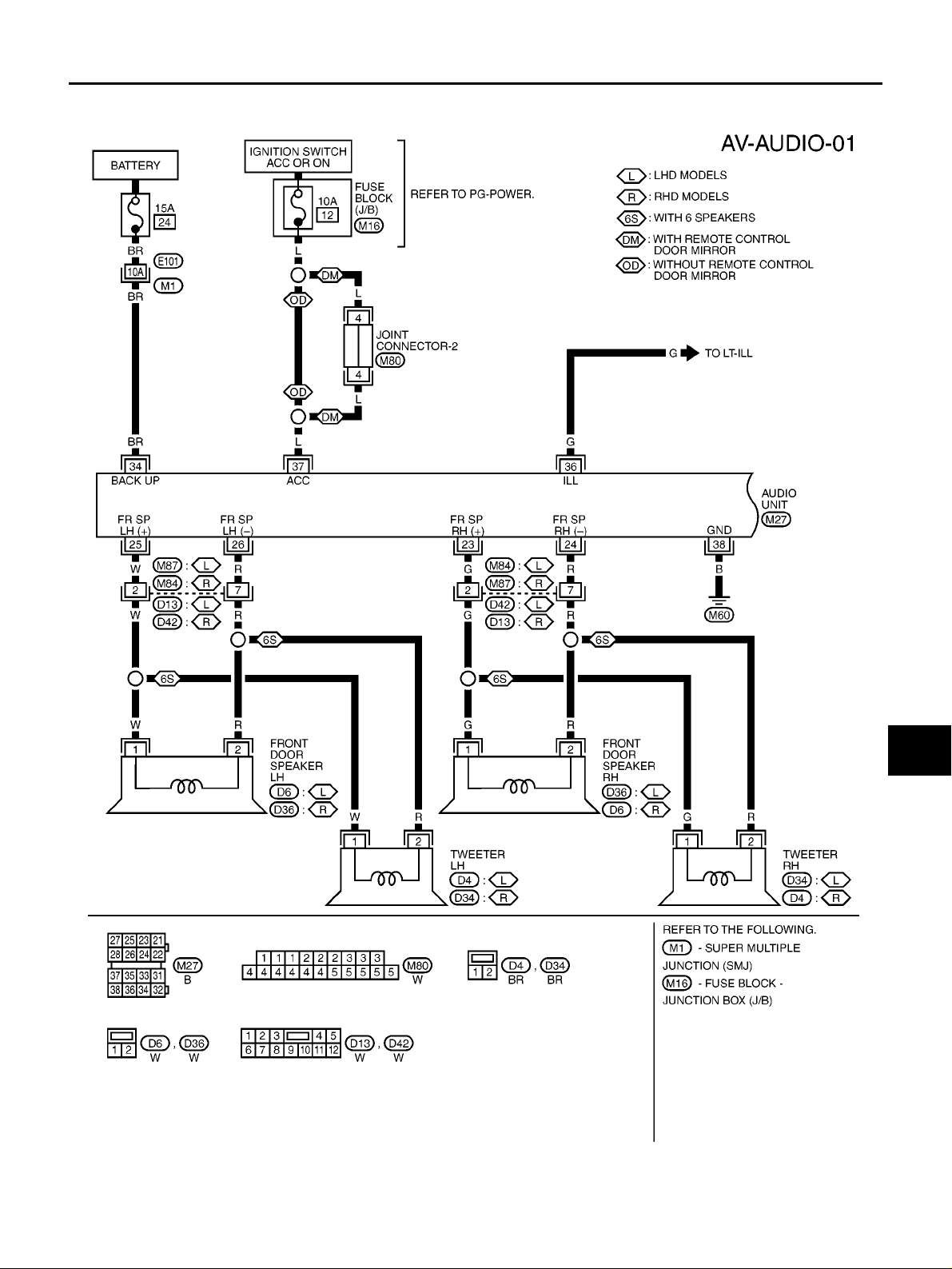
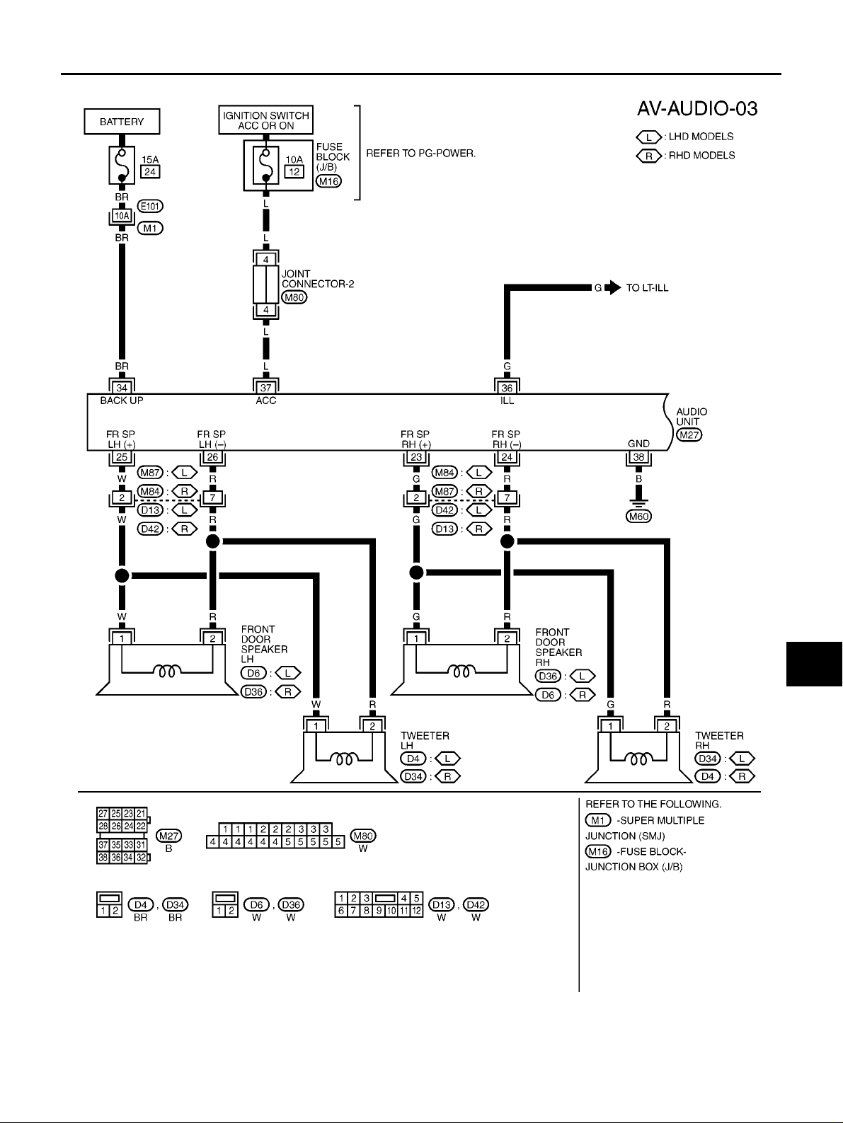
AUDIO SYSTEM
Refer to Owner’s Manual for audio system operating instructions.
Power is supplied at all times
● through 15A fuse (No. 24, located in the fuse and fusible link box)
● to audio unit terminal 34,
With the ignition switch in the ACC or ON position, power is supplied
● through 10A fuse [No. 12, located in the fuse block (J/B)]
● to audio unit terminal 37,
Ground is supplied through the case of the audio unit.
Ground is also supplied
● through body ground M60,
● to audio unit terminal 38.
Audio signals are supplied
● through audio unit terminals 21, 22, 23, 24, 25, 26, 27, 28
● to terminals 1 and 2 of front door speaker LH and RH
● to terminals 1 and 2 of rear door speaker LH and RH (hatchback models)
● to terminals 1 and 2 of rear speaker top and low (C+C models)
● to terminals 1 and 2 of tweeter LH and RH.
When one of steering wheel audio control switches is pushed to volume down or seek down, resistance in
steering switch circuit changes depending on which button is pushed. This will change voltage. Power is supplied
● from audio unit terminal 11
● through combination switch (spiral cable) terminals 33 and 15
● to steering wheel audio control switch.
Ground is supplied
● from steering wheel audio control switch
● through combination switch (spiral cable) terminals 16 and 32
● from audio unit terminal 12.
When one of steering wheel audio control switches is pushed to volume up, seek up, or mode ON, resistance
in steering switch circuit changes depending on which button is pushed. This will change voltage. Power is
supplied
● from audio unit terminal 10
● through combination switch (spiral cable) terminals 34 and 14
● to steering wheel audio control switch.
Ground is supplied
● from steering wheel audio control switch
● through combination switch (spiral cable) terminals 16 and 32
● from audio unit terminal 12.
When opening or closing the roof, audio equalizer will change automatically. (C+C models)
AV-4
Page 5
AUDIO
Wiring Diagram —AUDIO—/Hatchback
WITHOUT ESP
EKS0077C
A
B
C
D
E
F
G
H
AV
I
J
L
M
AV-5
MKWA4244E
Page 6

AUDIO
AV-6
MKWA1383E
Page 7
WITH ESP
AUDIO
A
B
C
D
E
F
G
AV
H
I
J
L
M
AV-7
MKWA1819E
Page 8

AUDIO
AV-8
MKWA1820E
Page 9

AUDIO
Wiring Diagram —AUDIO—/C+C
EKS00QJX
A
B
C
D
E
F
G
H
AV
I
J
L
M
AV-9
MKWA3975E
Page 10

AUDIO
AV-10
MKWA3976E
Page 11

AUDIO
Terminals and Reference Value for Audio Unit
Terminal No.
(wire color)
(+) (–)
1 (PU)* Ground
5 (B)* Ground Ground - ON - Approx. 0V -
10 (L) Ground
11 (W) Ground
12 (L) -
Item
Roof up/down
equalizer
Remote control A
Remote control B
Remote control earth
Signal
input/
output
Output ON
Input ON
Input ON
- ON - Approx. 0V
Ignition
switch
Condition
Voltage Example of symptom
Operation
Roof closed Approx. 0V
Except for
above
PressMODE
switch
Press SEEK
UP switch
Press VOL
UP switch
Except for
above
Press SEEK
DOWN
switch
Press VOL
DOWN
switch
Except for
above
Approx. 0V
Approx. 1.68V
Approx. 3.34V
Approx. 5V
Approx. 1.68V
Approx. 3.34V
Approx. 5V
Audio equalizer dose not
change during open/
close motion of roof.
MIIB1360E
Steering wheel audio
controls do not function.
Steering wheel audio
controls do not function.
Steering wheel audio
controls do not function.
EKS0077E
A
B
C
D
E
F
G
H
I
J
AV
21 (LG) 22 (GY)
23 (G) 24 (R )
25 (W) 26 (R)
Speaker output (rear door
RH or rear
top*)
Speaker output (front door
RH)
Speaker output (front door
LH)
Output ON
Output ON
Output ON
Receive
radio broadcast
Receive
radio broadcast
Receive
radio broadcast
AV-11
SKIA0177E
SKIA0177E
SKIA0177E
No sound from rear door
RH or rear top* speaker.
No sound from front door
RH speaker or tweeter
RH.
No sound from front door
LH speaker or tweeter
LH.
L
M
Page 12

AUDIO
Terminal No.
(wire color)
(+) (–)
Item
Signal
input/
output
Speaker out-
27 (W) 28 (R)
put (rear door
LH or rear
Output ON
low*)
34 (BR) Ground Battery power Input OFF - Battery voltage
36 (G) Ground
Illumination
signal
Input ON
37 (L) Ground ACC power Input ACC - Battery voltage
Ignition
switch
Condition
Operation
Receive
radio broadcast
Lighting
switch is ON
(position 1).
Turn lighting
switch OFF.
Voltage Example of symptom
No sound from rear door
LH or rear low* speaker.
SKIA0177E
Audio unit operation is
not possible.
Battery voltage
Audio unit illumination
does not come on when
lighting switch is ON
Approx. 3.0V or less
(position 1).
Audio unit operation is
not possible.
38 (B) Ground Ground - ON - Approx. 0V -
*:C+C models only
Steering Wheel Audio Control Switch Resistance Check
Terminal
(+) (–)
14 (W)
15 (L)
16 (B)
Signal name Condition
Seek up
(next)
Depress (station) up switch. Approx.165
Mode Depress mode switch. Approx. 0
Volume (up) Depress volume up switch. Approx. 652
Seek down
(previous)
Volume
(down)
Depress (station) down switch. Approx. 165
Depress volume down switch. Approx. 652
Resistance
(Ω)
Trouble Diagnosis
● The majority of the audio troubles are the result of outside causes (bad CD electromagnetic interference,
EKS007AT
MKIB0264E
EKS0077J
etc.). Check the inspection items below to diagnose the malfunction.
PROBLEM WITH RADIO AND CD
Symptom Check items Possible cause
Inoperative
No sound
● Check that the ignition switch is in the ACC position.
● Check that the volume is not turned down.
● Check that the balance and fader control knobs are
centered.
Poor sound
● Check that the bass and treble adjustment knobs are
centered.
Noisy -
● Audio u nit
● Audio unit power circuit
● Audio u nit
● Audio unit power circuit
● Speaker
● Sound signal circuit between speaker
and Audio unit
● Audio u nit
● Speaker
● Audio u nit
● Each electrical equipment
AV-12
Page 13

FOR RADIO ONLY
Symptom Check items Possible cause
No sound
Noisy
Selected radio stations stored in
memory are deleted
AUDIO
● Check that the radio is tuned to a station's frequency.
● Check that the radio is tuned to a station's frequency.
● Check that the signal of the received station is not
weak.
● Check whether or not the malfunction occurs only in
a particular area. (Note)
-
● Audio u nit
● Antenna feeder
● Roof antenna
● Audio u nit
● Antenna feeder
● Roof antenna
● Noise prevention parts
● Each electrical equipment
● Wire harness of each piece of electri-
cal equipment
● Audio u nit
● Audio unit power circuit
A
B
C
D
E
NOTE:
● This is noise resulting from variations in field strength, such as fading noise and multi-path noise, or exter-
nal noise from trains and other sources. It is not a malfunction.
– Fading noise: This noise occurs because of variations in the field strength in a narrow range due to moun-
tains or buildings blocking the signal.
– Multi-path noise: This noise results from the waves sent directly from the broadcast station arriving at the
antenna at a different time from the waves which reflect off of mountains or buildings.
FOR CD ONLY
Symptom Check items Possible cause
The CD cannot be played.
The sound skips, stops suddenly,
or is distorted.
Noise Inspection
● Check that the CD is not upside down.
● Check that there is no dirt, damage, or water on the disc.
● Check that there is no dirt, damage, or water on the disc.
● Check that the trouble is not due to strong vibration.
● Audio u nit
EKS0077K
The vehicle itself can be a source of noise if noise prevention parts or electrical equipment is malfunction.
Check if noise is caused and/or changed by engine rotation, ignition switch turned to each position, and operation of each piece of electrical equipment, and determine the cause.
NOTE:
The source of the noise can be found easily by listening to the noise while removing the fuses of electrical
components, one by one.
TYPE OF NOISE AND POSSIBLE CAUSE
Occurrence condition Possible cause
A continuous gr owling noise occurs. The speed of the
noise varies with changes in the engine speed.
Occurs only when engine is ON.
A whistling noise occurs while the engine speed is
high. A booming noise occurs while the engine is running and the lighting switch is ON.
The occurrence of the noise is linked with the operation of the fuel pump.
A cracking or snapping sound occurs with the opera-
Noise only occurs when various
tion of various switches.
electrical components are operating.
The noise occurs when various motors are operating.
● Problem with the ignition condenser.
● Problem with the alternator
● Problem with the fuel pump condenser
● Relay malfunction, radio malfunction
● Problem with the motor case ground
● Problem with the motor
F
G
H
I
J
AV
L
M
AV-13
Page 14

AUDIO
Occurrence condition Possible cause
The noise occurs constantly, not just under certain conditions.
A cracking or snapping sound occurs while the vehicle is being driven, especially when it
is vibrating excessively.
● Rear defogger coil malfunction
● Open circuit in printed heater
● Po or gr ound of antenna amplifier or
antenna feeder line
● Problem with the ground wire of body
parts
● Problem with ground due to part installa-
tion problem
● Problem with wiring connections or a
short circuit
Power Supply Circuit Inspection
EKS0077L
1. CHECK FUSE
● Check that the following fuses of the audio unit are not blown. Refer to PG-127, "FUSE BLOCK - JUNC-
TION BOX (J/B)" and PG-128, "FUSE AND FUSIBLE LINK BOX" .
Terminals
Audio unit
Unit
Connector Terminal (wire color)
M27 34 (BR) Ground Battery power 24
M27 37 (L) Ground ACC power 12
(-)
Signal name Fuse No.(+)
OK or NG
OK >> GO TO 2.
NG >> If fuse is blown, be sure to eliminate cause of problem before installing new fuse. Refer to PG-5,
"POWER SUPPLY ROUTING" .
2. POWER SUPPLY CIRCUIT CHECK
Disconnect the connector. Check voltage between the following harness connector terminal (+) and body ground (-).
Terminal No. Ignition switch
Unit
Connector
Audio unit
OK or NG
OK >> Inspection end.
NG >> Repair or replace harness.
(+)
Terminal
(wire color)
M27 34 (BR) Ground
M27 37 (L) Ground 0V
(-) OFF ACC ON
Battery
power
Battery
voltage
Battery
voltage
Battery
voltage
Battery
voltage
MKIB0659E
Steering Wheel Audio Control Switch Does Not Operate
1. STEERING WHEEL AUDIO CONTROL SWITCH RESISTANCE CHECK
1. Disconnect steering wheel audio control switch connector.
2. Check resistance steering wheel audio control switch. Refer to AV-12, "
Switch Resistance Check" .
Resistance value is OK?
YESorNO
YES >> GO TO 2.
NO >> Replace steering wheel audio control switch.
AV-14
EKS007AU
Steering Wheel Audio Control
Page 15

AUDIO
2. STEERING WHEEL AUDIO CONTROL SWITCH CIRCUIT CHECK
1. Disconnect audio unit connector.
2. Check continuity between audio unit harness connector M26
and combination switch (spiral cable) harness connector M29.
Terminals
Connector
M26
Terminal
(wire color)
10 (L)
12 (L) 32 (L)
Connector
M29
Terminal
(wire color)
34 (L)
3. Check continuity between audio unit and ground.
Terminals
(+)
Connector
M26
Terminal
(wire color)
10 (L)
12 (L)
(-)
Ground No11 (W)
OK or NG
OK >> Check combination switch (spiral cable).
NG >> Replace audio unit.
Continuity
Yes11 (W) 33 (W)
Continuity
A
B
C
D
MKIB0660E
E
F
G
H
Removal and Installation of Audio Unit
REMOVAL
1. Remove instrument panel and cluster lid C. Refer to IP-7, "L. Cluster Lid C" .
2. Remove screws and remove audio unit and bracket.
3. Remove screws and remove bracket.
EKS0077N
MKIB0266E
I
J
AV
L
M
INSTALLATION
Install in the reverse order of removal.
MKIB0267E
AV-15
Page 16

AUDIO
Removal and Installation of Front Door Speaker
REMOVAL
1. Remove front door finisher. Refer to EI-20, "DOOR FINISHER" .
2. Remove screws and remove speaker.
INSTALLATION
Install in the reverse order of removal.
Removal and Installation of Rear Door Speaker (3 Door Models)
REMOVAL
1. Remove rear side finisher. Refer to EI-20, "DOOR FINISHER" .
2. Remove screws and remove speaker.
EKS0077O
MKIB0268E
EKS007PJ
INSTALLATION
Install in the reverse order of removal.
Removal and Installation of Rear Door Speaker (5 Door Models)
REMOVAL
1. Remove rear door finisher. Refer to EI-20, "DOOR FINISHER" .
2. Remove screws and remove speaker.
INSTALLATION
Install in the reverse order of removal.
MKIB0269E
EKS007PK
MKIB0268E
AV-16
Page 17

AUDIO
Removal and Installation of Rear Speaker (C+C Models)
REMOVAL
1. Remove rear seatback assembly. Refer to SE-19, "Removal and Installation (C+C)" .
2. Remove screws and remove rear speaker bracket.
3. Remove screws and remove rear speaker (Top/Low).
EKS00QB8
A
B
C
D
MKIB2196E
E
F
G
H
INSTALLATION
Install in the reverse order of removal.
Removal and Installation of Front Pillar Tweeter
REMOVAL
1. Remove front door finisher.Refer to EI-25, "BODY SIDE TRIM" .
2. Remove clips and remove corner cover.
3. Remove screws and remove front pillar tweeter.
INSTALLATION
Install in the reverse order of removal.
MKIB2197E
I
EKS0077P
J
AV
L
M
MKIB0272E
AV-17
Page 18

AUDIO ANTENNA
AUDIO ANTENNA
Location of Antenna
PFP:28200
EKS0077Q
AV-18
MKIB0262E
Page 19

AUDIO ANTENNA
Removal and Installation of Roof Antenna
REMOVAL
1. Remove headlining. Refer to EI-33, "HEADLINER" .
2. Remove roof antenna mounting nut, antenna plug. Then remove
roof antenna.
INSTALLATION
Install in the reverse order of removal.
EKS0077R
A
B
C
D
MKIB0271E
E
F
G
H
AV
I
J
L
M
AV-19
Page 20

NAVIGATION SYSTEM
NAVIGATION SYSTEM
Schematic
PFP:25915
EKS007T8
AV-20
MKWA3977E
Page 21

NAVIGATION SYSTEM
Wiring Diagram —NAVI—/Hatchback
WITHOUT ESP
EKS007T9
A
B
C
D
E
F
G
H
AV
I
J
L
M
AV-21
MKWA4245E
Page 22

NAVIGATION SYSTEM
AV-22
MKWA1823E
Page 23

NAVIGATION SYSTEM
A
B
C
D
E
F
G
AV
H
I
J
L
M
AV-23
MKWA3478E
Page 24

WITH ESP
NAVIGATION SYSTEM
AV-24
MKWA1824E
Page 25

NAVIGATION SYSTEM
A
B
C
D
E
F
G
AV
H
I
J
L
M
AV-25
MKWA1825E
Page 26

NAVIGATION SYSTEM
AV-26
MKWA3479E
Page 27

NAVIGATION SYSTEM
Wiring Diagram —NAVI—/C+C
EKS00QJY
A
B
C
D
E
F
G
H
AV
I
J
L
M
AV-27
MKWA3978E
Page 28

NAVIGATION SYSTEM
AV-28
MKWA3979E
Page 29

NAVIGATION SYSTEM
A
B
C
D
E
F
G
AV
H
I
J
L
M
AV-29
MKWA3980E
Page 30

NAVIGATION SYSTEM
AV-30
MKWA3981E
 Loading...