

Page 1

I BODY
A
B
SECTION
CONTENTS
PRECAUTIONS .......................................................... 3
Precautions for Supplemental Rest raint System
(SRS) “AIR BAG” and “SEAT BELT PRE-TEN-
SIONER” .................................................................. 3
Precautions .............................................................. 3
PREPARATION ........................................................... 4
Special Service Tools ............................................... 4
Commercial Service Tools ........................................ 4
SQUEAK AND RATTLE TROUBLE DIAGNOSIS ...... 5
Work Flow ................................................................ 5
CUSTOMER INTERVIEW ..................................... 5
DUPLICATE THE NOISE AND TEST DRIVE ....... 6
CHECK RELATED SERVICE BULLETINS .. ......... 6
LOCATE THE NOISE AND IDENTIFY THE
ROOT CAUSE ...................................................... 6
REP AIR THE CAUSE ........................................... 6
CONFIRM THE REPAIR ....................................... 7
Generic Squeak and Rattle Troubleshooting ........... 7
INSTRUMENT PANEL .......................................... 7
CENTER CONSOLE ............................................. 7
DOORS .............................. ................................... 7
TRUNK ............................... ................................... 8
SUNROOF/HEADLINER .......... ............. ................ 8
SEATS ................................................................... 8
UNDERHOOD .................... ............. ............. ......... 8
Diagnostic Worksheet .............................................. 9
CLIP AND FASTENER ..............................................11
Description ..............................................................11
FRONT BUMPER ..................................................... 14
Removal and Installation ........................................ 14
REAR BUMPER ....................................................... 16
Removal and Installation ........................................ 16
FRONT GRILLE ........................................................ 18
Removal and Installation ........................................ 18
COWL TOP ............................................................... 19
Removal and Installation ........................................ 19
FRONT FENDER ...................................................... 20
Removal and Installation ........................................ 20
EXTERIOR & INTERIOR
FRONT FENDER PROTECTOR ............................... 21
Removal and Installation ........................................ 21
FRONT ................................................................ 21
REAR ..................................................................22
MUDGUARD ............................................................. 23
Removal and Installation ........................................ 23
LICENSE LAMP FINISHER ...................................... 24
Removal and Installation ........................................ 24
REAR AIR SPOILER ................................................ 25
Removal and Installation ........................................ 25
ROOF SIDE MOLDING .............................................26
Removal and Installation ........................................ 26
REAR PILLAR FINISHER .........................................27
Removal and Installation ........................................ 27
DOOR OUTSIDE MOLDING ..................................... 28
Removal and Installation ........................................ 28
FRONT DOOR OUTSIDE MOLDING .................. 28
REAR DOOR OUTSIDE MOLDING ... ...... ....... ....28
SIDE GUARD MOLDING .......................................... 29
Removal and Installation ........................................ 29
REMOVAL ...................... ..................................... 29
INSTALLATION ........................... ........................29
DOOR FINISHER ...................................................... 30
Removal and Installation ........................................ 30
FRONT DOOR .................................................... 30
REAR DOOR ..... ....... ...... ....... ...... ....... ...... ....... ....31
BODY SIDE TRIM ..................................................... 32
Removal and Installation ........................................ 32
CENTER PILLAR LOWER GARNISH ................. 33
CENTER PILLAR UPPER GARNISH .................. 33
REAR PILLAR FINISHER ................................... 33
DASH SIDE FINISHER .......................................33
REAR PARCEL SHELF FINISHER ..........................34
Removal and Installation ........................................ 34
SUNSHADE .............................................................. 35
Component Parts and Harness Connector Location ...35
Wiring Diagram —SHADE— ..................................36
Removal and Installation ........................................ 38
FLOOR TRIM ............................................................ 39
Removal and Installation ........................................ 39
C
D
E
F
G
H
EI
J
K
L
M
EI-1
Page 2

HEADLINING ............................................................ 40
Removal and Installation ........................................40
TRUNK ROOM TRIM & TRUNK LID FINISHER .......42
Removal and Installation .........................................42
EI-2
Page 3

PRECAUTIONS
PRECAUTIONS PFP:00001
Precautions for Supplemental Restraint System (SRS) “AIR BAG” and “SEAT BELT PRE-TENSIONER”
EIS001K3
A
The Supplemental Re straint System such as “AIR BAG” and “SEAT BELT PRE-TENSIONER”, used along
with a front seat belt, helps to reduce the risk or severity of injury to the driver and front passenger for certain
types of collision. This system includes seat belt switch inputs and dual st age front air bag modules. The SRS
system uses the seat belt switches to determine the front air bag deployment, and may only deploy one front
air bag, depending on the severity of a collision and whether the front occupants are belted or unbelted.
Information necessary to service the system safely is included in the SRS and SB section of this Service Manual.
WARNING:
● To avoid rendering the SRS inopera tive, whi ch could incr ease the risk of pe rsonal injury or death
in the event of a collision which would result in air bag inflation, all maintenance must be performed by an authorized NISSAN/INFINITI dealer.
● Improper maintenance, inc luding incorrect removal and installation of the SRS, can lead to per-
sonal injury ca use d by unintentional ac tiv atio n o f the system. For remo va l of Spiral Cable and Air
Bag Module, see the SRS sec tion.
● Do not use electrical test equ ipment o n any circu it related to the SRS unless in structed to in this
Service Manual. SRS wiring harnesses can be identified by yellow and/or orange harness connectors.
Precautions
● When removing or disassembling any part, be careful not to damage or deform it. Protect parts which may
EIS001K4
get in the way with cloth.
● When removing parts with a screwdriver or other tool, protect parts by wrapping them with vinyl or tape.
● Keep removed parts protected with cloth.
● If a clip is deformed or damaged, replace it.
● If an unreusable part is removed, replace it with a new one.
● Tighten bolts and nuts firmly to the specified torque.
● After re-assembly has been completed, make sure each part functions correctly.
● Remove stains in the following way.
– Water-soluble stains:
Dip a cloth in warm water, and squeeze tightly. After wiping the stain, wipe with a soft dry cloth.
– Oil stain:
Dissolve a synthetic detergent in warm water (density of 2 to 3% or less), dip the cloth, then clean off the
stain with the c loth. Nex t, dip the soft clo th in fres h water, and then sq ueeze it tightly. Then clean off the
detergent completely. Then wipe the area with a soft dry cloth.
● Do not use any organic solvent, such as thinne r or benzine.
B
C
D
E
F
G
H
EI
J
K
L
M
EI-3
Page 4
PREPARATION
PREPARATION
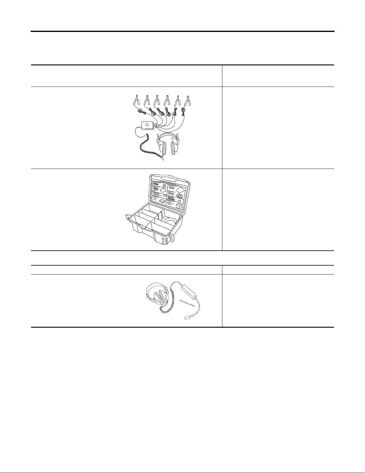
Special Service Tools
The actual shapes of Kent-Moore tools may differ from those of special service tools illustrated here.
Tool number
(Kent-Moore No.)
Tool name
(J-39570)
Chassis ear
SBT839
(J-43980)
NISSAN Squeak and Rattle kit
Description
Locating the noise
Repairing the cause of noise
PFP:00002
EIS001K5
SBT840
Commercial Service Tools
Tool name Description
Engine ear Locating the noise
SIIA0995E
EIS001K6
EI-4
Page 5
SQUEAK AND RATTLE TROUBLE DIAGNOSIS
SQUEAK AND RATTLE TROUBLE DIAGNOSIS PFP:00000
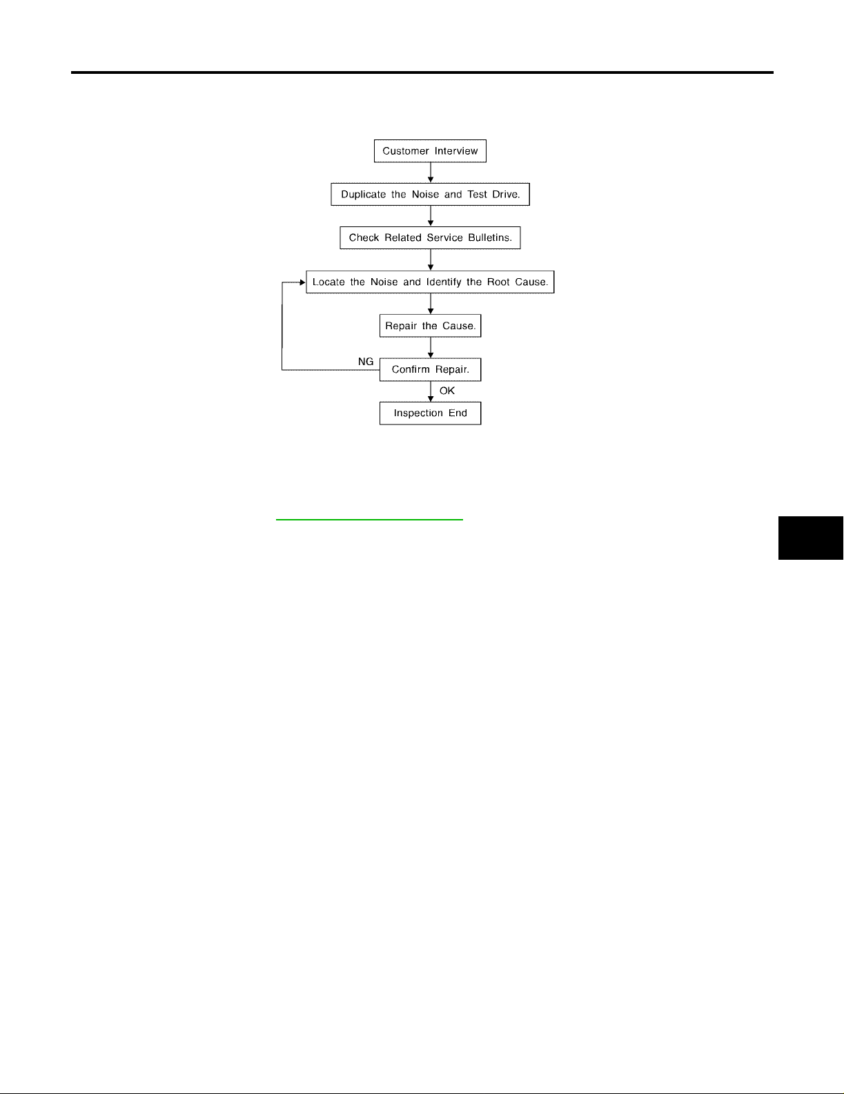
Work Flow
EIS001K7
A
B
C
D
E
F
SBT842
CUSTOMER INTERVIEW
Interview th e cust omer, if possi ble, t o dete rmi ne th e condit ion s that exis t when the no ise oc curs . Us e the Di agnostic Worksheet during the interview to docume nt the facts and conditions w hen the noise occurs and an y
customer's comments; refer to EI-9, "
conditions that exist when the noise occurs.
● The customer may not be able to provide a detailed description or the location of the noise. Attempt to
obtain all the facts and conditions that exist when the noise occurs (or does not occur).
● If there is more than one noise in the vehicle, be sure to diagnose and repair the noise that the customer
is concerned about. This can be accomplished by test driving the vehicle with the customer.
● After ident if yi ng th e t y pe of no is e, i so lat e th e no is e in t er ms o f i t s c ha r ac te ris t ic s. T he n oi se c ha ract e ris ti cs
are provided so the customer, service adviser and technician are all speaking the same language when
defining the noise.
– Squeak — (Like tennis shoes on a clean floor)
Squeak charact eristics include the lig ht contact/fast movement/ brought on by road condi tions/hard surfaces = higher pitch noise/softer surfaces = lower pitch noises/edge to surface = chirping
– Creak — (Like walking on an old wooden floor)
Creak characteristics include firm contact/slow movement/twisting with a rotational movement/pitch
dependent on materials/often brought on by activity.
– Rattle — (Like shaking a baby rattle)
Rattle charact eristics inclu de the f ast repe ated co ntact/vibra tion or similar mov ement/l oose parts/mi ssing
clip or fastener/incorrect clearance.
– Knock — (Like a knock on a door)
Knock characteristics include hollow sounding/sometimes repeating/often brought on by driver action.
– Tick — (Like a clock second hand)
Tick characteristics include gentle contacting of light materials/loose components/can be caused by driver
action or road co nditions.
– Thump — (Heavy, muffled knock noise)
Thump characteristics include softer knock/d ead sound often brought on by activity.
– Buzz — (Like a bumblebee)
Buzz characteristics include high freque ncy rattle/firm contact.
● Often the de gree of acceptable nois e level will vary d epending upon the person. A noise that you may
judge as acceptable may be very irritating to the custome r.
● Weather conditions, especially humidit y and temperature, may have a great effect on noise level.
Diagnostic Worksheet" . This information is necessary to duplicat e the
G
H
EI
J
K
L
M
EI-5
Page 6

SQUEAK AND RATTLE TROUBLE DIAGNOSIS
DUPLICATE THE NOISE AND TEST DRIVE
If possible, drive the vehicle with the customer until the noise is duplicated. Note any additional information on
the Diagnostic Worksheet regarding the con ditions or location of the noise. This inform ation can be used to
duplicate the same conditions when you confirm the repair.
If the noise can be duplicated easily during the test drive, to help identify the source of the noise, try to duplicate the noise with the vehicle stopped by doin g one or all of the following:
● Close a door.
● Ta p or push/pull a round the area where the noise appears to be coming from.
● Rev the engine.
● Use a floor jack to recreate vehicle “twist”.
● At idle, apply engine load (electrical load, half-clutch on M/T mode l, drive position on A/T model).
● Raise the vehicle on a hoist and hit a tire with a rubber hammer.
● Drive the vehicle and attempt to duplicate the conditions the customer states exist when the noise occurs.
● If it is difficult to duplicate the nois e, drive th e vehic le slowly on an und ulating or ro ugh road t o stress the
vehicle body.
CHECK RELATED SERVICE BULLETINS
After verifying the customer concern or symptom, check ASIST for Technical Service Bulletins (TSBs) related
to that concern or symptom.
If a TSB relates to the symptom, follow the pr ocedure to repair the nois e.
LOCATE THE NOISE AND IDENTIFY THE ROOT CAUSE
1. Narrow down the nois e to a general area. To help pinpoint the source of the noise, use a lis tening tool
(Chassis Ear: J-39570, Engine Ear: J-39565 and mechanics stethoscope).
2. Narrow down the noise to a more specific area and identify the cause of the noise by:
● Removing the components in t he area that you su spect the noise is coming from.
Do not use too much force when removing c lips and fasteners, otherwise cl ips and fasteners
can be broken or lost during the repair, resulting in the creation of new noise.
● Tapping or pushing/pulling the component that you suspect is causing the noise.
Do not tap or push/pull t he compone nt with excess ive force, othe rwise the noise will be elimi nated only temporarily.
● Feeling for a vibration with your hand by touching the component(s) that you suspect is (are) causing
the noise.
● Placing a piec e of paper between components that you suspect are causing the noise.
● Looking for loose components and contact marks.
Refer to EI-7, "
Generic Sque ak and Rattle Troubles hooting" .
REPAIR THE CAUSE
● If the cause is a loose component, tighten the component secur ely.
● If the cause is insufficient clearance between components:
– Separate components by repositioning or loosening and retightening the component, if possible.
– Insulate components with a suitable insulator such as urethane pads, foam blocks, felt cloth tape or ure-
thane tape. A NISSAN Squeak and Rattle Kit (J-43980) is available through your authorized NISSAN
Parts Department.
CAUTION:
Do not use excessive force as many components are constructed of plastic and may be damaged.
Always check with the Parts Department for the latest parts informat ion.
The following materials are contained in the NISSAN Squeak and Rattle Kit (J-43980). Each item can be
ordered separately as needed.
URETHANE PADS [1.5 mm (0.059 in) thick]
Insulates connectors, harness, etc.
76268-9E005: 100 x 135 mm (3.94 x 5.31 in)/76884-71L01: 60 x 85 mm (2.36 x 3.35 in)/76884-71L02: 15 x 25
mm (0.59 x 0.98 in)
INSULATOR (Foam blocks)
Insulates components from contact. Can be used to fill space behind a panel.
EI-6
Page 7

SQUEAK AND RATTLE TROUBLE DIAGNOSIS
73982-9E000: 45 mm (1. 7 7 in) t hick , 5 0 x 5 0 mm (1. 97 x 1.97 in ) /739 82 -50 Y 00 : 10 mm ( 0.39 in ) th ic k, 50 x 50
mm (1.97 x 1.97 in)
INSULATOR (Light foam block)
80845-71L00: 30 mm (1.18 in) thick, 30 x 50 mm (1.18 x 1.97 in)
FELT CLOTH TAPE
Used to insulate where movement does not occur. Ideal for instrum ent panel applications.
68370-4B000: 15 x 25 mm (0.59 x 0.98 in) pad/6 8239-13E00: 5 mm (0.20 in) wide tape roll
The following materials, not found in the kit, can also be used to repair squeaks and rattles.
UHMW (TEFLON) TAPE
Insulates where slight movement is present. Ideal for instrument panel applications.
SILICONE GREASE
Used in place of UHMW tape that will be visible or not fit.
Note: Will only last a few months.
SILICONE SPRAY
Use when greas e cannot be applied.
DUCT TAPE
Use to elimin ate movement.
A
B
C
D
E
CONFIRM THE REPAIR
Confirm that the cause of a noise is repaired by test driving the vehicle. Operate the vehicle under the same
conditions as when the noise originally occurred. Refer to the notes on the Diagnostic Worksheet.
Generic Squeak and Rattle Troubleshooting
Refer to Table of Contents for specific component removal and installation information.
EIS001K8
INSTRUMENT PANEL
Most incidents are caused by contact and movement between:
1. The cluster lid A and instrument panel
2. Acrylic lens and combination meter hous ing
3. Instrument panel to front pillar garnish
4. Instrument panel to windshield
5. Instrument panel mounting pins
6. Wiring harnesses behind the combination meter
7. A/C defroster duct and duct joint
These incidents can usually be located by tapping or moving the components to duplicate the noise or by
pressing on the co mponents while drivi ng to s top the noise. Most of th es e in c ide nts c an be re paired by applying felt cloth tape or silicone spray (in hard to reach are as) . Ur et ha ne pads ca n be use d to in su la te wiring harness.
CAUTION:
Do not use silicone s pray to isolate a sq ueak or rattle. If you saturate the area with silicone, you w ill
not be able to recheck the repair.
CENTER CONSOLE
Components to pay attention to include:
1. Shifter assembly cover to finisher
2. A/C control unit and upper/lower clus ter lid C
3. Wiring harnes se s be hin d audio and A/C control unit
The instrument panel repair and isolation procedures also apply to the center console.
F
G
H
EI
J
K
L
M
DOORS
Pay attention to the:
1. Finisher and inner panel making a slapping noise
2. Inside handle escutcheon to door finisher
3. Wiring harnesses tapping
4. Door striker out of alignment causing a popping noise on starts and stops
EI-7
Page 8

SQUEAK AND RATTLE TROUBLE DIAGNOSIS
Tapping or moving the components or pressing on them while driving to duplicate the conditions can isolate
many of thes e incidents. You can usuall y insulat e the areas with fel t cloth tape o r insula tor foam bl ocks from
the NISSAN Squeak and Rattle Kit (J-43980) to repair the noise.
TRUNK
Trunk noises are often caused by a loose jack or loose items put into the trun k by the owner.
In addition look for:
1. T runk lid bumpers out of adjustment
2. T runk lid striker out of adjustment
3. The trunk lid torsion bars knocking together
4. A loose l icense plate or b racket
Most of these incidents can be repaired by adjusting, securing or insulating the item(s) or compo nent(s) causing the noise.
SUNROOF/HEADLINER
Noises in the sunroof/headliner area can often be traced to one of the following:
1. Sunroof lid, rail, linkage or seals making a rattle or light knocking noise
2. Sunvisor shaft shaking in the holder
3. Front or rear windshiel d touching headliner and squeaking
Again, pressing on the components to stop the noise while duplicating the conditions can isolate most of these
incidents. Repairs usually consist of insulating with felt cloth tape.
SEATS
When isolatin g seat noises it is important to n ote the positio n the seat is in and the load pl aced on the se at
when the noise is present. These conditions should be duplicated when verifying and isolating the cause of
the noise.
Cause of seat noise include:
1. Headrest rods and holders
2. A squeak between the seat pad cushion and frame
3. The rear seat back lock and bracket
These noises can be isolated by moving or pressing on the suspected components while duplicating the conditions under wh ic h th e n ois e oc cu rs. Most of these inci dents can be repaired by rep os iti oning the compone nt
or applying urethane tape to the contact area.
UNDERHOOD
Some interior noises may be cause d by compon ents under the ho od or on the eng ine wall. Th e noise is th en
transmitted into the passenger compartment.
Causes of transmitted underhood noises inc lude:
1. Any component mounted to the engine wall
2. Compon ents that pass through the engine wall
3. Engine wall mounts and connectors
4. Loose radiator moun tin g pi ns
5. Hood bumpers out of adjus tm e nt
6. Hood striker out of adjustment
These noises can be difficu lt to isol ate sin ce the y cann ot be rea ched from the inter ior of the ve hi cle. The best
method is to sec ure, mov e or insul ate one com ponen t at a time and test drive the vehicle . Also , engine RPM
or load can be cha nged to isol ate the noise. Repairs can usu ally be made by moving, adj usting, securing, or
insulating the component causing the noise.
EI-8
Page 9
SQUEAK AND RATTLE TROUBLE DIAGNOSIS
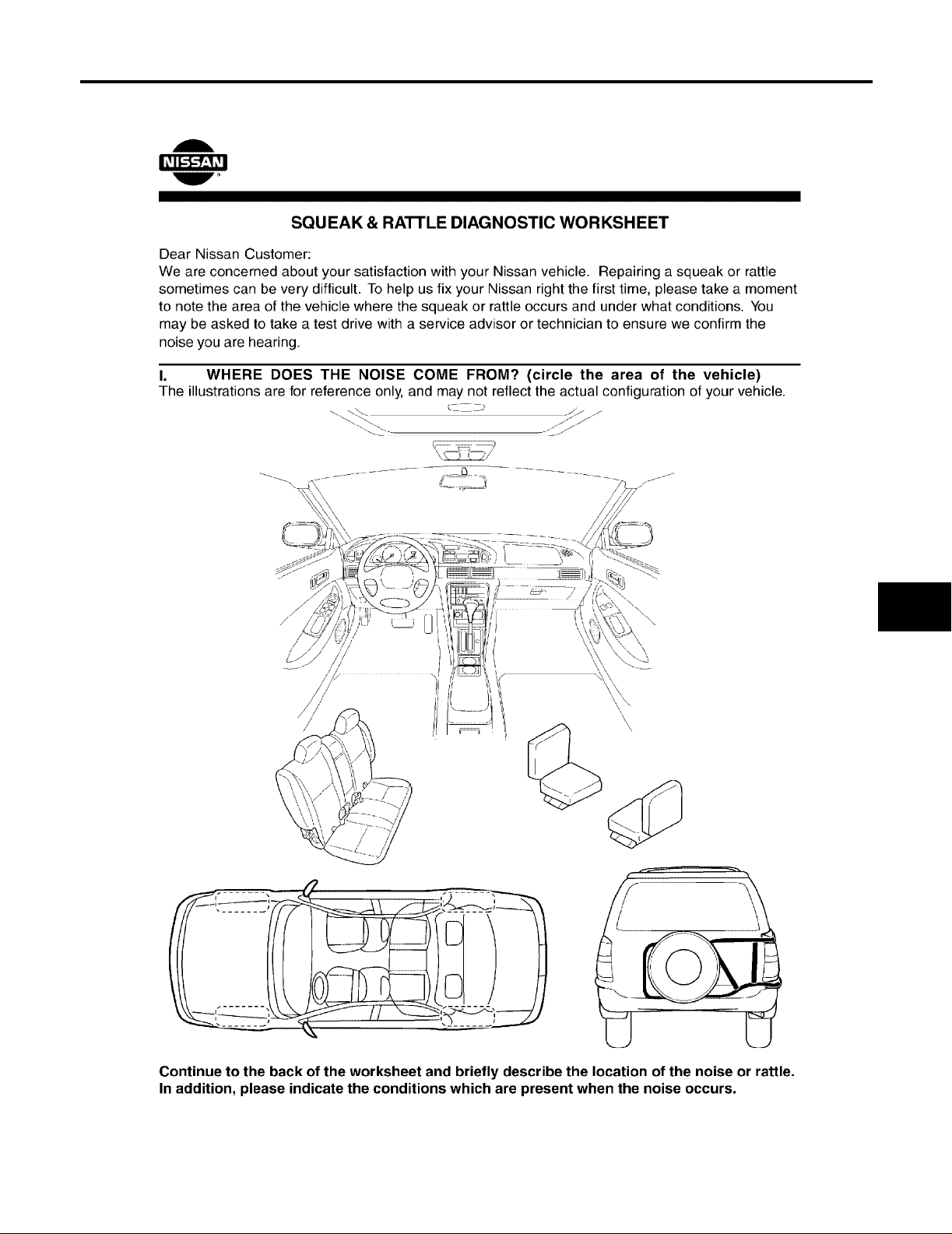
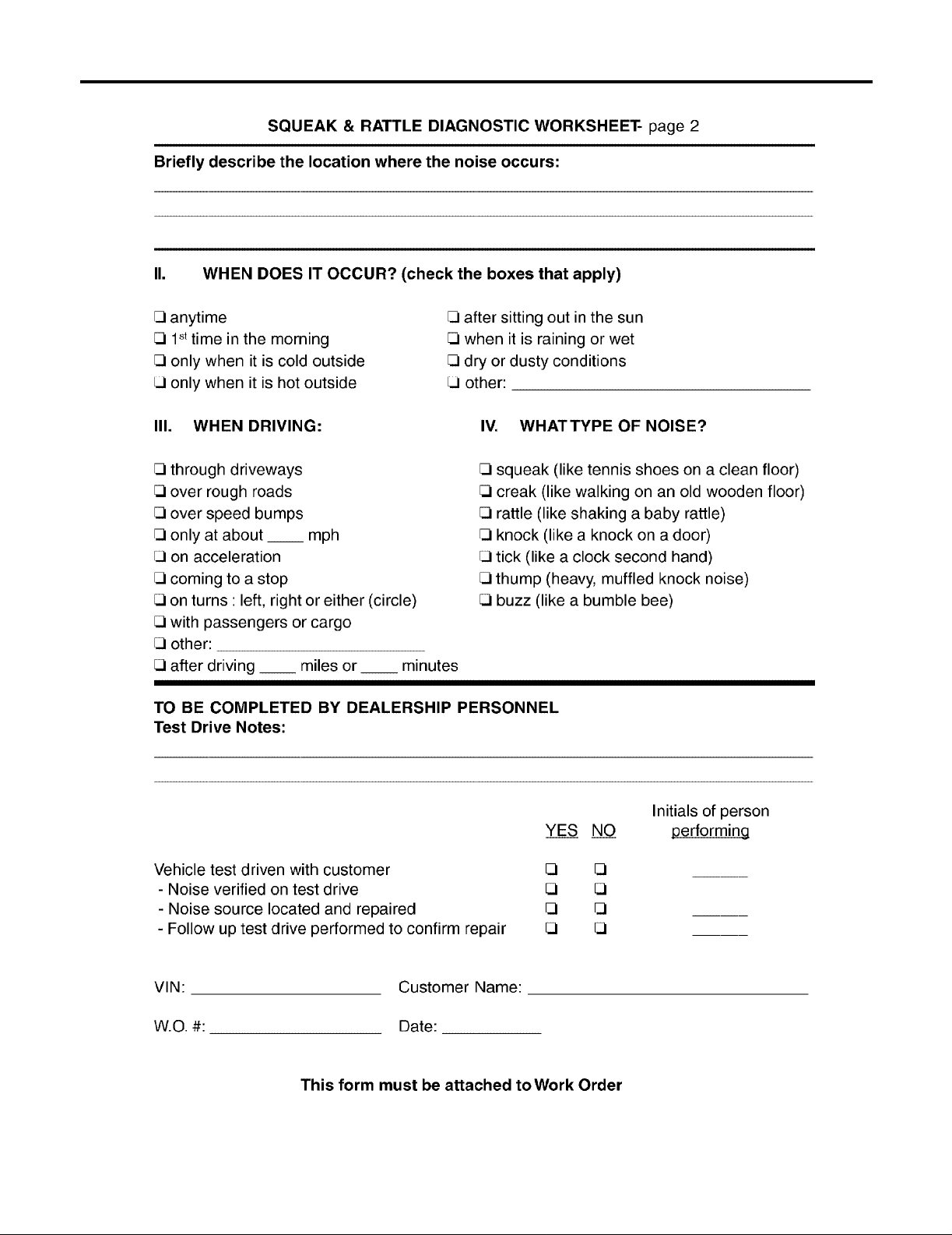
Diagnostic Worksheet
EIS001K9
A
B
C
D
E
F
G
H
EI
J
K
L
M
EI-9
SBT843
Page 10
SQUEAK AND RATTLE TROUBLE DIAGNOSIS
EI-10
SBT844
Page 11
CLIP AND FASTENER
CLIP AND FASTENER PFP:76906
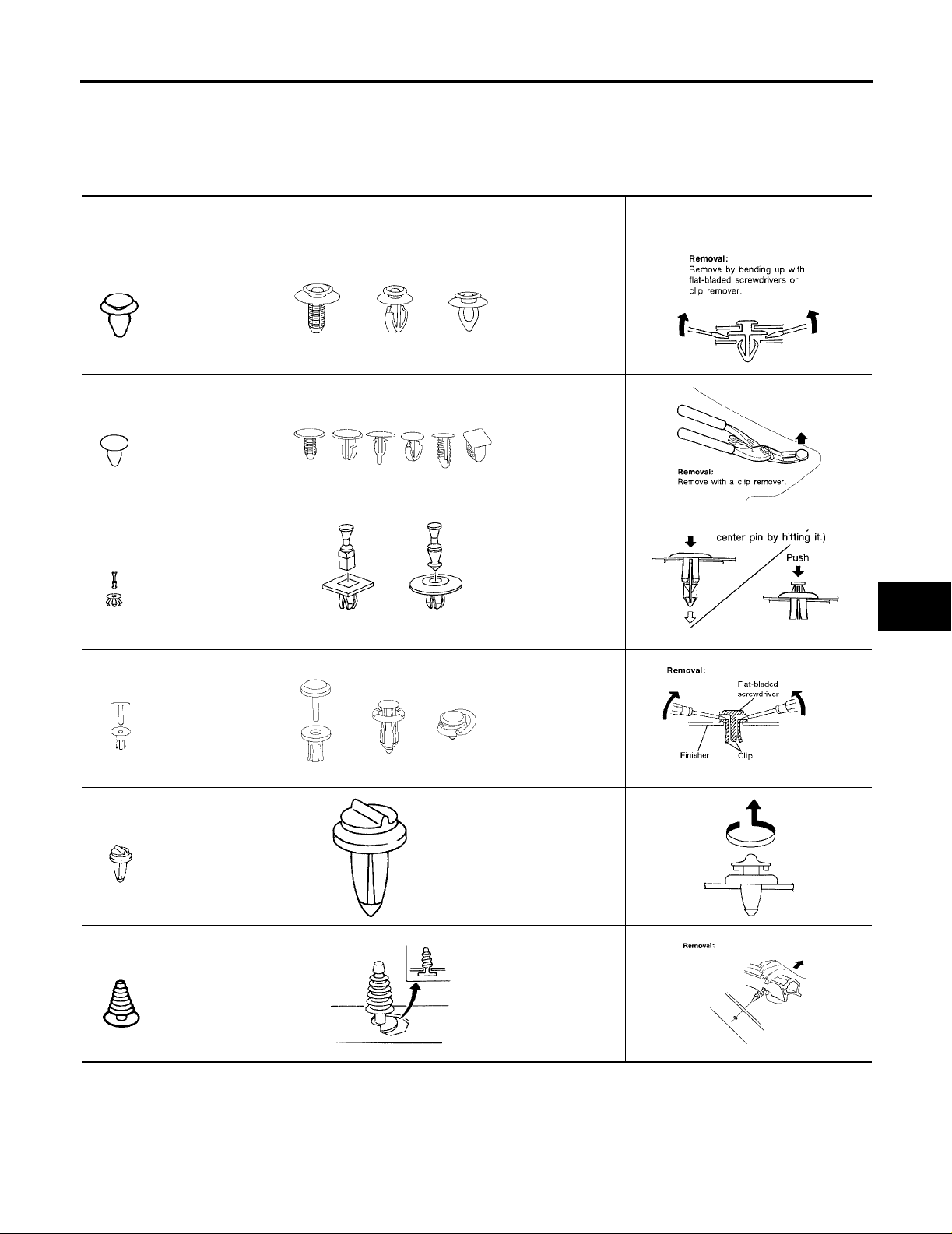
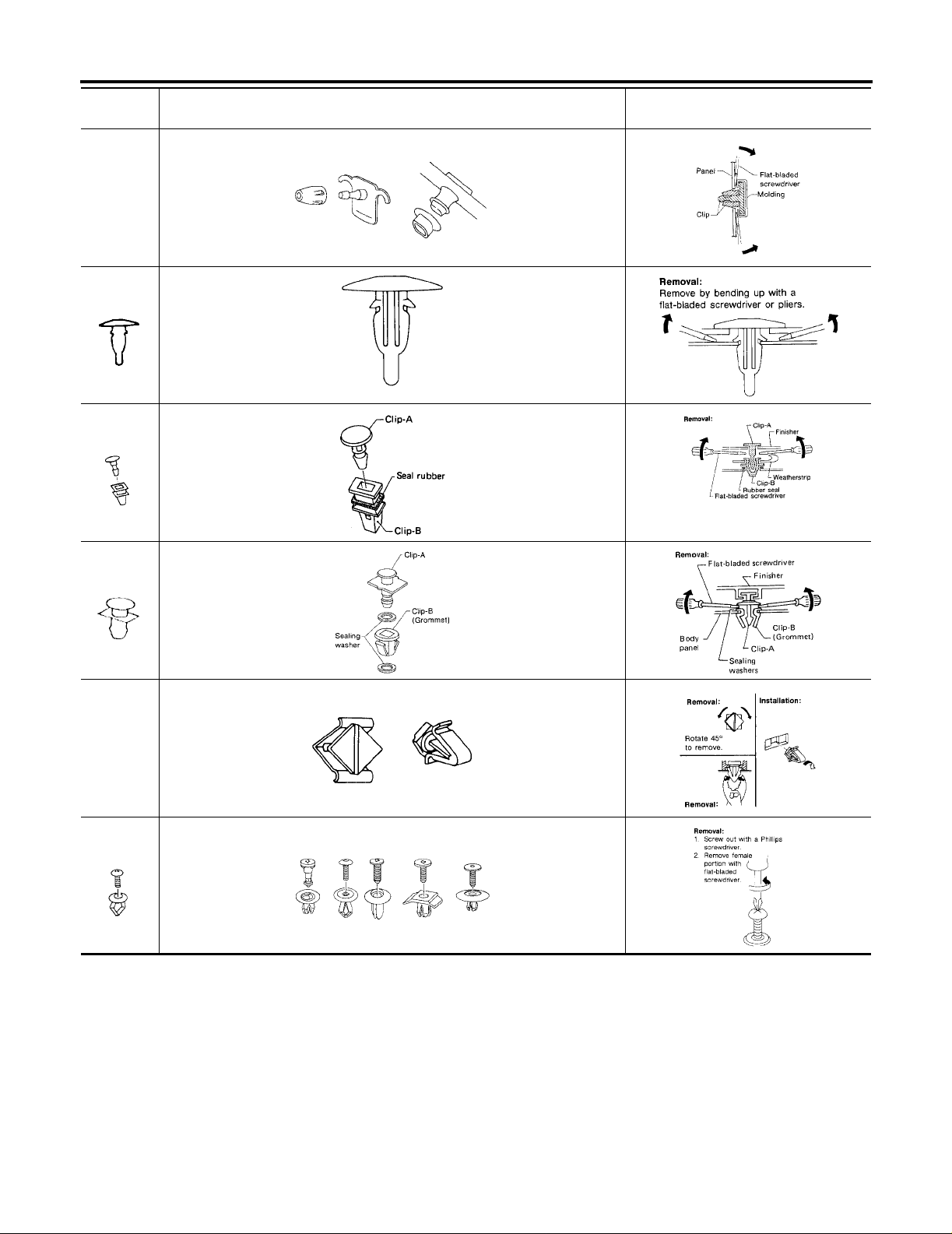
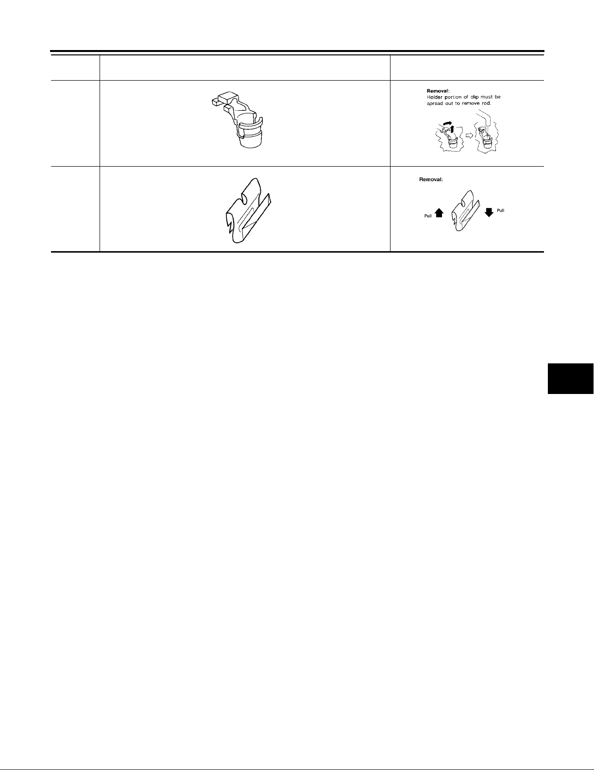
Description
● Clips and fasteners in EI section correspond to the following numbers and symbols.
● Replace any clips and/or fasteners which are damaged during r emoval or installation.
EIS001KA
A
B
Symbol
No.
C101
C103
C203
Shapes Removal & Installation
SBF302H SBF367BA
SBT095 SBF423H
SBF258G SBF708E
C
D
E
F
G
H
EI
C205
C206
CE103
J
K
MBT080A SBF638CA
L
M
MBF519B MBF520B
SBF104B SBF147B
EI-11
Page 12
CLIP AND FASTENER
Symbol
No.
CE107
CE117
CF110
Shapes Removal & Installation
SBF411H SBF767B
SBF174D SBF175DA
SBF648B SBF649B
CF118
CG101
CS101
SBF151D SBF259G
SBF145B SBF085B
SBF078B SBF992G
EI-12
Page 13
CLIP AND FASTENER
Symbol
No.
CR103
Metal Clip
Shapes Removal & Installation
SBF768B SBF770B
WBT072 WBT073
A
B
C
D
E
F
G
H
EI
J
K
L
M
EI-13
Page 14
FRONT BUMPER
FRONT BUMPER
Removal and Installation
PFP:F2022
EIS001KB
EI-14
WIIA0164E
Page 15

FRONT BUMPER
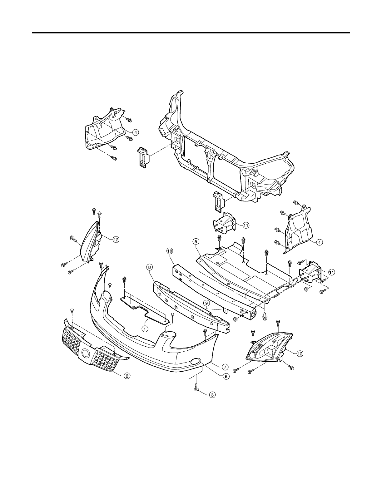
1. Remove grille top cover.
2. Remove radiator grille. Refer toEI-18, "
3. Remove scr ews on each side o f b ottom of fascia th at attach fascia to bo tto m of fender protec tor. Partially
remove fender protector. Refer to EI-21, "
4. Remove engine underside cover s .
5. Remove engine front undercover.
6. Unplug connectors to cornering lights in fascia.
7. Remove front bumper fascia.
8. Pull off energy absorbing foam from front bumper.
9. Unplug ambient temperature sensor where it is attached to front bumper reinforcement.
10. Remove front bumper reinforcement.
11. Remove front bumper supports.
12. Unplug harnesses and remove headlight assemblies.
Installation is in the reverse order of removal.
FRONT GRILLE" .
FRONT FENDER PROTECTOR" .
A
B
C
D
E
F
G
EI
H
J
K
L
M
EI-15
Page 16

REAR BUMPER
REAR BUMPER
Removal and Installation
PFP:H5022
EIS001KC
EI-16
WIIA0165E
Page 17

REAR BUMPER
1. Remove rear tr unk p la te an d partially remo ve t ru nk side f i nish er s . R efe r to EI-42, "TRUNK ROOM TRIM &
TRUNK LID FINISHER" .
2. Remove rear combination lamps. Refer to LT-148, "
3. Remove rear bumper fascia.
● If fascia is to be replaced, remove bracket from fascia.
4. Remove energy absorber from rear bumper rein forcement.
5. Remove rear bumper reinforcement.
Installation is in the reverse order of removal.
REAR COMBINAT ION LAMP" .
A
B
C
D
E
F
G
EI
H
J
K
L
M
EI-17
Page 18

FRONT GRILLE
FRONT GRILLE
Removal and Installation
PFP:62310
EIS001KD
1. Remove 4 clips attaching grille top cover and remove grille top cover.
2. Remove 4 clips on top of radiator grille.
3. Remove radiator grille.
● Pull out of 4 tabs on the bottom.
Installation is in the reverse order of removal.
EI-18
WIIA0166E
Page 19

COWL TOP
COWL TOP PFP:66100
Removal and Installation
EIS001KE
A
B
C
D
E
F
G
WIIA0167E
1. Remove both th e ri ght an d lef t wip er arm s fr om the ve hicl e. Re fer to WW-29, "Removal and Installation for
Front Wiper Arms, Adjustment for Wiper Arms Stop Location" .
2. Remove fender covers.
3. Remove clips attaching cowl top cover and remove cowl top cover.
4. Disconnect windshield washer hose.
5. Remove cowl top seal.
6. Remove cowl weather-strip seal.
7. Remove windshield washer nozzles and hoses from cowl. Refer to WW-31, "
Washe r Tube Layout" .
Installation is in the reverse order of removal.
H
EI
J
K
L
M
EI-19
Page 20

FRONT FENDER
FRONT FENDER
Removal and Installation
1. Remove front combination lamp. Refer to LT-41, "Combination Lamp Removal and Installation" .
2. Remove fender protector. Refer to EI-21, "
3. Remove fr ont half of center mud guard. Refer to EI-23, "
4. Remove fr ont fender.
Installation is in the reverse order of removal.
Removal and Installation" .
Removal and Installati on" .
PFP:63100
EIS001KF
LIIA0281E
EI-20
Page 21

FRONT FENDER PROTECTOR
FRONT FENDER PROTECTOR PFP:63840
Removal and Installation
FRONT
EIS001KG
A
B
C
D
E
F
G
1. Remove screws.
2. Remove pushpins.
3. Remove clips.
4. Remove front fender protector.
Installation is in the reverse order of removal.
WIIA0168E
H
EI
J
K
L
M
EI-21
Page 22

REAR
FRONT FENDER PROTECTOR
1. Remove clips.
2. Remove nuts.
3. Remove rear fender protector.
Installation is in the reverse order of removal.
WIIA0196E
EI-22
Page 23

MUDGUARD
MUDGUARD PFP:63854
Removal and Installation
EIS001KH
A
B
C
D
E
F
G
1. Remove screws.
2. Release cl ips.
3. Remove center mudguard.
Installation is in the reverse order of removal.
WIIA0169E
H
EI
J
K
L
M
EI-23
Page 24

LICENSE LAMP FINISHER
LICENSE LAMP FINISHER
Removal and Installation
1. Remove trunk lid finisher. Refer to EI-42, "TRUNK ROOM TRIM & TRUNK LID FINISHER" .
2. Remove nuts from license lamp finisher.
3. Remove license lamp finisher.
Installation is in the reverse order of removal.
PFP:84810
EIS001KI
WIIA0170E
EI-24
Page 25

REAR AIR SPOILER
REAR AIR SPOILER PFP:K6030
Removal and Installation
EIS001NE
A
B
C
D
E
F
WIIA0171E
1. Nuts 2. Clips 3. Clip retainers
4. Double sided tape 5. Rear air spoiler
1. Remove trunk lid finisher. Refer to EI-42, "TRUNK ROOM TRIM & TRUNK LID FINISHER" .
2. Remove three nuts attaching spoiler to trunk lid.
CAUTION:
Use care not to damage paint on trunk and not to damage spoiler if it is to be replaced.
3. Using a trim stick, carefully remove spoiler by pr ying adhesive free.
NOTE:
Before installing spoiler, clean surface where spoiler will be mounted with isopropyl alcohol or equivalent to
degrease the surface.
Installation is in the reverse order of removal.
● When installing, make sure that there are not any gaps or w aves at the ends of the spoiler.
G
H
EI
J
K
L
M
EI-25
Page 26

ROOF SIDE MOLDING
ROOF SIDE MOLDING
Removal and Installation
1. Remove rear pillar finisher. Refer toEI-27, "REAR PILLAR FINISHER" .
2. Lift an d twist roof side molding up fro m rear edge.
3. Disconnect clips, and remove roof side molding.
Installation is in the reverse order of removal.
PFP:73854
EIS001KK
LIIA0534E
EI-26
Page 27

REAR PILLAR FINISHER
REAR PILLAR FINISHER PFP:76934
Removal and Installation
EIS001NF
A
B
C
D
E
F
1. Remove screw in bottom corner of rear pillar finisher.
2. Using a trim stick, release clips and remove finisher.
Installation is in the reverse order of removal.
WIIA0172E
G
H
EI
J
K
L
M
EI-27
Page 28

DOOR OUTSIDE MOLDING
DOOR OUTSIDE MOLDING
Removal and Installation
PFP:82820
EIS001KL
FRONT DOOR OUTSIDE MOLDING
Removal and Installation
1. Open window s fully.
2. Lift and twist molding from rear side, di sconnect clips from flange and remove moldin g.
Installation is in the reverse order of removal.
REAR DOOR OUTSIDE MOLDING
Removal and Installation
1. Open window s fully.
2. Lift and twist molding from rear side, and disconnect clips from flange and remove molding.
Installation is in the reverse order of removal.
LIIA0282E
EI-28
Page 29

SIDE GUARD MOLDING
SIDE GUARD MOLDING PFP:76840
Removal and Installation
EIS001KM
A
B
C
D
E
F
LIIA0072E
REMOVAL
CAUTION:
Never apply tack-paper adhesive remover to body panel surface finished with lacquer-based paints.
● Original side guard molding is affixed to body panel wi th double-faced adhesive tape.
1. Heat molding to be tw ee n 30° and 40°C (86° to 104°F) with a heat gun.
2. Raise end of molding and cut away tape to remove molding.
3. Remove all traces of tape.
INSTALLATION
● On vehicles coat ed w ith H a rd Cl ea r Coat , us e do ub l e-f ac ed 3M adh esi ve t ap e P rod uc t No . 4 21 0 o r equ iv -
alent, after priming with 3M primer Product No. N200 or C-100 or equivalent.
● The repair parts are also affixed with double-faced adhesive tape.
● To re-use existing molding, clean all traces of double sided tape from the molding and apply new double-
faced tape to the molding.
1. Clean the panel surface with isopropyl alcohol or equivalent to degrease the surface.
2. Heat the panel and molding tape surface to 30° to 40°C (86° to 104°F).
3. Remove the backing sheet from the tape surface.
4. Press ends by hand and use a roller to apply 5 kg-f (11 lbs.-f) to press molding to door surface.
CAUTION:
To secure contact, do not wash vehicle for 24 hours after installation.
G
H
EI
J
K
L
M
EI-29
Page 30

DOOR FINISHER
DOOR FINISHER
Removal and Installation
FRONT DOOR
PFP:80900
EIS001KN
1. Remove screw cover from handle escutcheon and remove screw.
2. Remove switch plate and disconnect harnesses.
3. Remove tr im molding from armrest.
4. Remove screws attaching door finisher to inner door.
5. Remove door finisher.
6. Disconnect harness and remove step light.
7. Disconnect harness and remove trunk opener and fuel door opener switch ass embly.
8. Disconnect lock cable and handle cable and remove handle assembly. Refer to BL-68, "
LOCK" .
Installation is in the reverse order of removal.
EI-30
WIIA0173E
FRONT DOOR
Page 31

REAR DOOR
DOOR FINISHER
A
B
C
D
E
F
G
1. Remove screw cover from handle escutcheon and remove screw.
2. Remove switch plate and disconnect harnesses.
3. Remove trim molding from armrest.
4. Remove 2 screws attaching door finisher to inner door.
5. Remove door finisher.
6. Disconnect harness from step light.
7. Disconnect lock cable and handle cable.
Installation is in the reverse order of removal.
H
EI
J
K
L
WIIA0174E
M
EI-31
Page 32

BODY SIDE TRIM
BODY SIDE TRIM
Removal and Installation
PFP:76913
EIS001KO
CAUTION:
● Wrap the tip of flat-bladed screwdriver with a cloth when removing metal clips from garnishes.
● When removing or installing body side welts, do not allow butyl sea l to com e in co ntact with pillar
garnish.
WIIA0175E
1. Front pillar garnish 2. Dash side finisher 3. Front kicking plate
4. Center pillar lower garnish 5. Rear kicking plate 6. Rear pillar finisher
7. Rear pillar garnish 8. Rear body side welt 9. Seat belt shoulder anchor cover
10. Center pillar upper garnish 11. Front body side welt
EI-32
Page 33

BODY SIDE TRIM
CENTER PILLAR LOWER GARNISH
Removal and Installation
1. Remove front and rear kicking plates.
2. Remove center pillar lower garnish.
Installation is in the reverse order of removal.
CENTER PILLAR UPPER GARNISH
Removal and Installation
1. Remove seat belt shoulder anchor. Refer to SB-4, "Removal and Installation of Front Seat Belt" .
2. Remove front and rear kicking plate.
3. Remove center pillar lower garnish.
4. Remove bolt covers and bolts.
5. Remove center pillar upper garnish.
Installation is in the reverse order of removal.
REAR PILLAR FINISHER
Removal and Installation
1. Remove bolt cover and bolt.
2. Remove rear pillar finisher.
Installation is in the reverse order of removal.
A
B
C
D
E
F
G
DASH SIDE FINISHER
Removal and Installation
1. Remove front kicking plate.
2. Remove dash side finisher.
CAUTION:
Insert screw driver rolled with cloth betwe en panel on vehicle
and clips (as indicated with arrow), and disconnect clips.
Installation is in the reverse order of removal.
H
EI
J
K
SIIA0810E
L
M
EI-33
Page 34

REAR PARCEL SHELF FINISHER
REAR PARCEL SHELF FINISHER
Removal and Installation
PFP:79910
EIS001KP
1. Remove rear seat. Refer to SE-110, "REAR SEAT" .
2. Remove rear seat belt anchor bolts. Refer to SB-5, "
3. Remove rear pillar finisher. Refer to EI-32, "
BODY SIDE TRIM" .
Removal and Installatio n of Rea r Seat Bel t" .
4. Remove high mounted stop lamp and disconnect connectors.
5. Remove halo trim.
6. Remove rear parcel shelf trim.
Installation is in the reverse order of removal.
WIIA0176E
WIIA0177E
EI-34
Page 35

SUNSHADE
SUNSHADE PFP:97580
Component Parts and Harness Connector Location
EIS001NP
A
B
C
D
E
F
G
LIIA0433E
H
EI
J
K
L
M
EI-35
Page 36

SUNSHADE
Wiring Diagram —SHADE—
EIS001NQ
EI-36
LIWA0072E
Page 37

SUNSHADE
A
B
C
D
E
F
G
EI
H
J
K
L
M
EI-37
WIWA0155E
Page 38

SUNSHADE
Removal and Installation
EIS001NH
1. Remove rear parcel shelf finisher. Refer to EI-34, "REAR PARCEL SHELF FINISHER" .
2. Remove screws.
3. Disconnect wiring harness.
4. Remove re ar sunshade.
Installation is in the reverse order of removal.
WIIA0178E
EI-38
Page 39

FLOOR TRIM
FLOOR TRIM PFP:74902
Removal and Installation
EIS001KQ
A
B
C
D
E
F
G
1. Remove lower body side trim. Refer to EI-32, "BODY SIDE TRIM" .
2. Remove front seats. Refer to SE-104, "
3. Remove rear seat cushion. Refer to SE-110, "
● On 4 seat model, remove seat backs.
4. Remove center console. Refer to IP-10, "
FRONT SEAT" .
REAR SEAT" .
INSTRUMENT PANEL ASSEMBLY" .
5. Remove lower seat belt anchors. Refer to SB-4, "SEAT BELTS" .
6. Remove servic e mat brackets.
7. Remove rear seat cushion hooks.
8. Remove carpet.
Installation is in the reverse order of removal.
LIIA0327E
H
EI
J
K
L
M
EI-39
Page 40

HEADLINING
HEADLINING
Removal and Installation
PFP:73910
EIS001KR
WIIA0179E
1. Headlining skyview roof 2. Headlining sun roof 3. Assist grips
4. Interior lamp assembly 5. Sunvisors 6. Cap, RH
7. Holder, sunvisor assembly, LH 8. Console assembly, roof 9. Holder, sunvisor assembly, LH
10. Cap, LH
EI-40
Page 41

HEADLINING
CAUTION:
Disconnect both terminals from battery in advance.
1. Remove front and rear door kicking plates. Refer to EI-32, "
2. Remove lower dash side trim. Refer to EI-32, "
BODY SIDE TRIM" .
3. Remove fron t pillar garn ish, ce nter pill ar lower an d upper garnish , and rea r pillar ga rnish. Re fer to EI-32,
"BODY SIDE TRIM" .
4. Remove front and rear door welts. Refer to EI-32, "
BODY SIDE TRIM" .
5. Remove assist grips.
6. Remove interior lamp assembly.
7. Remove roof console assembly.
8. Remove RH and LH caps from sunvisor mounting brackets.
9. Remove screws from each sunvisor mounting bracket and remove sunvisors.
10. Remove sunvisor assembly holders.
11. Remove windshield garnish molding. Refer to EI-32, "
12. Remove clips attaching headlining to roof.
13. Take out headlining from the left re ar door.
Installation is in the reverse order of removal.
BODY SIDE TRIM" .
BODY SIDE TRIM" .
A
B
C
D
E
F
G
EI
H
J
K
L
M
EI-41
Page 42

TRUNK ROOM TRIM & TRUNK LID FINISHER
TRUNK ROOM TRIM & TRUNK LID FINISHER
Removal and Installation
PFP:84920
EIS001KS
1. Trunk forward carpet 2. Trim clips 3. Trim clips
4. Upper trunk finisher 5. Trunk net 6. Trunk room lamp
7. Trim clips 8. Trunk floor carpet 9. Trunk net, RH
10. Trunk net hooks 11. Trim clips 12. Trunk side finisher, RH
EI-42
WIIA0180E
Page 43

TRUNK ROOM TRIM & TRUNK LID FINISHER
13. Trim clips 14. Box assembly 15. Rear trunk plate
16. Trim clips 17. Trunk finisher, rear 18. Trim clips
19. Trunk lid finisher 20. Spare tire cover 21. Trunk side finisher, LH
22. Trunk net, LH 23. Trunk net hooks 24. Trim clips
25. Trim clips
A
B
C
D
E
F
G
EI
H
J
K
L
M
EI-43
Page 44

TRUNK ROOM TRIM & TRUNK LID FINISHER
EI-44
 Loading...