

Page 1

MAINTENANCE
CONTENTS
PRECAUTIONS ...............................................................3
Precautions for Supplemental Restraint System
(SRS) ″AIR BAG″ and ″SEAT BELT
PRE-TENSIONER″......................................................3
PREPARATION ...............................................................4
Special Service Tool....................................................4
PRE-DELIVERY INSPECTION ITEMS............................5
GENERAL MAINTENANCE............................................6
PERIODIC MAINTENANCE (FOR EUROPE).................7
Maintenance Schedule for Petrol Engines
(Annual Mileage < 30,000 km/year)............................7
VQ ENGINE
CHASSIS AND BODY MAINTENANCE
Maintenance Under Severe Driving Conditions
(Annual Driving Distance < 30,000 km/year)..............9
Maintenance Schedule for Petrol Engines
(Annual Mileage > 30,000 km/year)..........................10
VQ ENGINE
CHASSIS AND BODY MAINTENANCE
Maintenance Under Severe Driving Conditions
(Annual Driving Distance > 30,000 km)....................12
RECOMMENDED FLUIDS AND LUBRICANTS...........13
Fluids and Lubricants ................................................13
SAE Viscosity Number ..............................................14
Engine Coolant Mixture Ratio....................................14
ENGINE MAINTENANCE..............................................15
Checking Drive Belts.................................................15
Changing Engine Coolant..........................................16
- DRAINING ENGINE COOLANT -
- REFILLING ENGINE COOLANT -
- FLUSHING COOLING SYSTEM -
Checking Cooling System .........................................19
CHECKING HOSES
CHECKING RADIATOR
CHECKING RADIATOR CAP
CHECKING COOLING SYSTEM FOR LEAKS
Checking Fuel Lines..................................................20
Changing Air Cleaner Filter .......................................20
VISCOUS PAPER TYPE
Changing Engine Oil..................................................21
..............................................................7
........................8
............................................................10
......................11
............................16
...........................17
............................18
.................................................19
............................................19
....................................19
............20
...........................................20
SECTION
Changing Oil Filter.....................................................21
Changing Spark Plugs (Platinum-tipped Type).........22
Checking Positive Crankcase Ventilation (PCV)
System.......................................................................23
CHECKING PCV VALVE
CHECKING VENTILATION HOSES
Checking Vacuum Hose and Connections................23
Checking EVAP Vapor Lines.....................................24
Checking Heated Oxygen Sensor (HO2S)................24
CHECKING PROCEDURE
CHASSIS AND BODY MAINTENANCE.......................25
Checking Exhaust System.........................................25
Checking Clutch Fluid Level and Leaks....................25
Checking Clutch System ...........................................25
Checking M/T Oil.......................................................25
Changing M/T Oil.......................................................26
Checking A/T Fluid ....................................................26
Changing A/T Fluid....................................................27
Balancing Wheels (Bonding Weight Type)................27
REMOVAL
WHEEL BALANCE ADJUSTMENT
Tire Rotation..............................................................29
Checking Brake Fluid Level and Leaks.....................29
Checking Brake Lines and Cables............................29
Changing Brake Fluid................................................29
Checking Brake Booster, Vacuum Hoses,
Connections and Check Valve ..................................30
Checking Disc Brake.................................................30
ROTOR
CALIPER
PAD
Checking Steering Gear and Linkage.......................31
STEERING GEAR
STEERING LINKAGE
Checking Power Steering Fluid and Lines................31
Lubricating Locks, Hinges and Hood Latches...........31
Checking Seat Belts, Buckles, Retractors,
Anchors and Adjusters...............................................32
Checking Body Corrosion..........................................32
...............................................................27
...................................................................30
.................................................................30
........................................................................30
MA
...........................................23
...........................23
........................................24
............................27
....................................................31
...............................................31
Page 2

CONTENTS (Cont’d)
SERVICE DATA AND SPECIFICATIONS (SDS).........33
Engine Maintenance..................................................33
BELT DEFLECTION AND TENSION
..........................33
SPARK PLUG (PLATINUM-TIPPED TYPE)
Chassis and Body Maintenance................................33
WHEEL BALANCE
...................................................33
................33
MA-2
Page 3

PRECAUTIONS
Precautions for Supplemental Restraint System (SRS) “AIR BAG” and “SEAT BELT PRE-TENSIONER”
Precautions for Supplemental Restraint System
(SRS) “AIR BAG” and “SEAT BELT
PRE-TENSIONER”
The Supplemental Restraint System such as “AIR BAG” and “SEAT BELTPRE-TENSIONER” used along with
a seat belt, helps to reduce the risk or severity of injury to the driver and front passenger for certain types of
collision. The SRS system composition which is available to NISSAN MODEL A33 is as follows (The composition varies according to the destination and optional equipment.):
+ For a frontal collision
The Supplemental Restraint System consists of driver air bag module (located in the center of the steering wheel), front passenger air bag module (located on the instrument panel on passenger side), seat belt
pre-tensioners, a diagnosis sensor unit, warning lamp, wiring harness and spiral cable.
+ For a side collision
The Supplemental Restraint System consists of front side air bag module (located in the outer side of front
seat), satellite sensor, diagnosis sensor unit (one of components of air bags for a frontal collision), wiring
harness, warning lamp (one of components of air bags for a frontal collision).
Information necessary to service the system safely is included in the RS section of this Service Manual.
WARNING:
+ To avoid rendering the SRS inoperative, which could increase the risk of personal injury or death
in the event of a collision which would result in air bag inflation, all maintenance should be performed by an authorized NISSAN dealer.
+ Improper maintenance, including incorrect removal and installation of the SRS, can lead to per-
sonal injury caused by unintentional activation of the system. For removal of Spiral Cable and Air
Bag Module, see the RS section.
+ Do not use electrical test equipment on any circuit related to the SRS unless instructed to in this
Service Manual. Spiral cable and wiring harnesses covered with yellow insulation tape either just
before the harness connectors or for the complete harness are related to the SRS.
NFMA0001
MA-3
Page 4
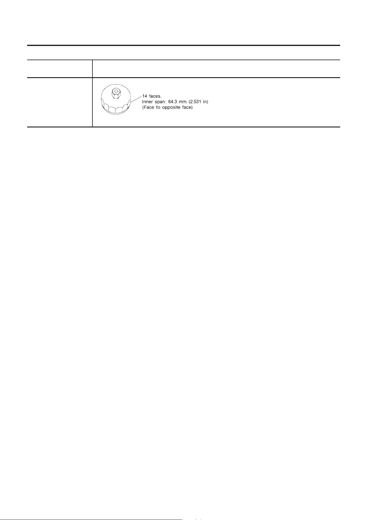
Special Service Tool
PREPARATION
Tool number
Tool name
KV10115801
KV10115800
(Kent-Moore Europe
make)
Oil filter wrench
Description
NT362
Special Service Tool
Removing oil filter
NFMA0002
MA-4
Page 5
NFMA0036
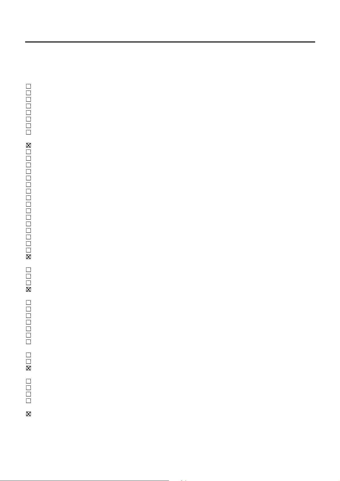
PRE-DELIVERY INSPECTION ITEMS
Shown below are Pre-delivery Inspection Items required for the new vehicle. It is recommended that
necessary items other than those listed here be added, paying due regard to the conditions in each
country.
Perform applicable items on each model. Consult text of this section for specifications.
UNDER HOOD — engine off
Radiator coolant level and coolant hose connections for leaks
Battery fluid level, specific gravity and conditions of battery terminals
Drive belts tension
Fuel filter for water or dusts, and fuel lines and connections for leaks
Engine oil level and oil leaks
Clutch and brake reservoir fluid level and fluid lines for leaks
Windshield and rear window washer and headlamp cleaner reservoir fluid level
Power steering reservoir fluid level and hose connections for leaks
ON INSIDE AND OUTSIDE
Remove front spring/strut spacer (If applicable)
Operation of all instruments, gauges, lights and accessories
Operation of horn(s), wiper and washer
Steering lock for operation
Check air conditioner for gas leaks
Front and rear seats, and seat belts for operation
All moldings, trims and fittings for fit and alignment
All windows for operation and alignment
Hood, trunk lid, door panels for fit and alignment
Latches, keys and locks for operation
Weatherstrips for adhesion and fit
Headlamp aiming
Tighten wheel nuts (Inc. inner nuts if applicable)
Tire pressure (Inc. spare tire)
Check front wheels for toe-in
Install clock/voltmeter/room lamp fuse (If applicable)
Install deodorizing filter to air conditioner (If applicable)
Remove wiper blade protectors (If applicable)
UNDER BODY
Manual transmission/transaxle, transfer and differential gear oil level
Brake and fuel lines and oil/fluid reservoirs for leaks
Tighten bolts and nuts of steering linkage and gear box, suspension, propeller shafts and drive shafts
Tighten rear body bolts and nuts (Models with wooden bed only)
ROAD TEST
Clutch operation
Parking brake operation
Service brake operation
Automatic transmission/transaxle shift timing and kickdown
Steering control and returnability
Engine performance
Squeaks and rattles
ENGINE OPERATING AND HOT
Adjust idle speed
Automatic transmission/transaxle fluid level
Engine idling and stop knob operation (Diesel only)
FINAL INSPECTION
Install necessary parts (outside mirror, wheel covers, seat belts, mat, carpet or mud flaps)
Inspect for interior and exterior metal and paint damage
Check for spare tire, jack, tools (wheel chock), and literature
Wash, clean interior and exterior
: Not applicable to this model
MA-5
Page 6
NFMA0004
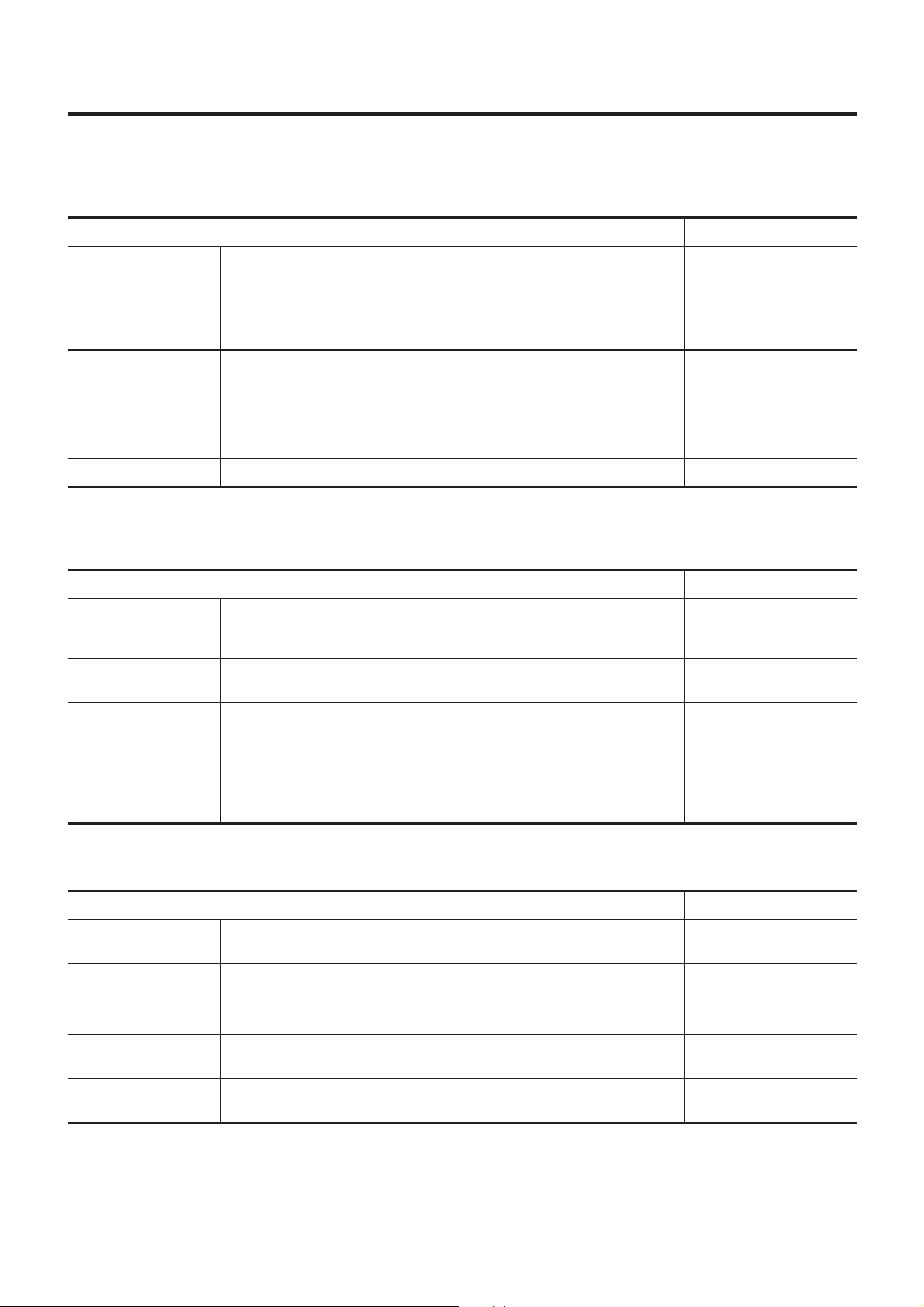
GENERAL MAINTENANCE
General maintenance includes those items which should be checked during the normal day-to-day operation
of the vehicle. They are essential if the vehicle is to continue operating properly. The owners can perform the
checks and inspections themselves or they can have their NISSAN dealers do them for a nominal charge.
OUTSIDE THE VEHICLE
The maintenance items listed here should be performed from time to time, unless otherwise specified.
Item Reference page
Tires Check the pressure with a gauge periodically when at a service station,
including the spare, and adjust to the specified pressure if necessary. Check
carefully for damage, cuts or excessive wear.
—
Windshield wiper
blades
Doors and engine
hood
Tire rotation Tires should be rotated every 10,000 km (6,000 miles). MA-29
Check for cracks or wear if they do not wipe properly. —
Check that all doors, the engine hood, the trunk lid and back door operate
properly.Also ensure that all latches lock securely. Lubricate if necessary.
Make sure that the secondary latch keeps the hood from opening when the
primary latch is released.
When driving in areas using road salt or other corrosive materials, check for
lubrication frequently.
MA-31
INSIDE THE VEHICLE
The maintenance items listed here should be checked on a regular basis, such as when performing periodic maintenance, cleaning the
vehicle, etc.
Item Reference page
Lamps Make sure that the headlamps, stop lamps, tail lamps, turn signal lamps,
and other lamps are all operating properly and installed securely. Also check
headlamp aim.
Warning lamps and
chimes
Steering wheel Check for change in the steering conditions, such as excessive free play,
Make sure that all warning lamps and chimes are operating properly. —
hard steering or strange noises.
Free play: Less than 35 mm (1.38 in)
—
—
Seat belts Check that all parts of the seat belt system (e.g. buckles, anchors, adjusters
and retractors) operate properly and smoothly, and are installed securely.
Check the belt webbing for cuts, fraying, wear or damage.
MA-32
UNDER THE HOOD AND VEHICLE
The maintenance items listed here should be checked periodically e.g. each time you check the engine oil or refuel.
Item Reference page
Windshield washer
fluid
Engine coolant level Check the coolant level when the engine is cold. MA-17
Engine oil level Check the level after parking the vehicle on a level spot and turning off the
Brake and clutch
fluid levels
Battery Check the fluid level in each cell. It should be between the “MAX” and “MIN”
Check that there is adequate fluid in the tank. —
engine.
Make sure that the brake and clutch fluid levels are between the “MAX” and
“MIN” lines on the reservoir.
lines.
MA-21
MA-25, 29
—
MA-6
Page 7
NFMA0043
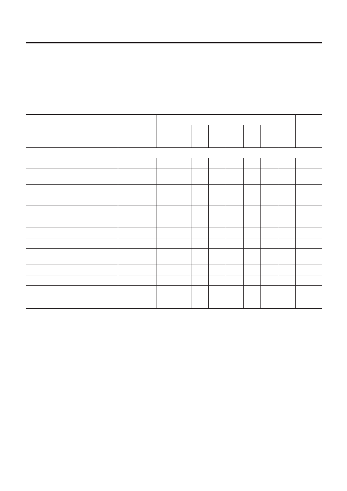
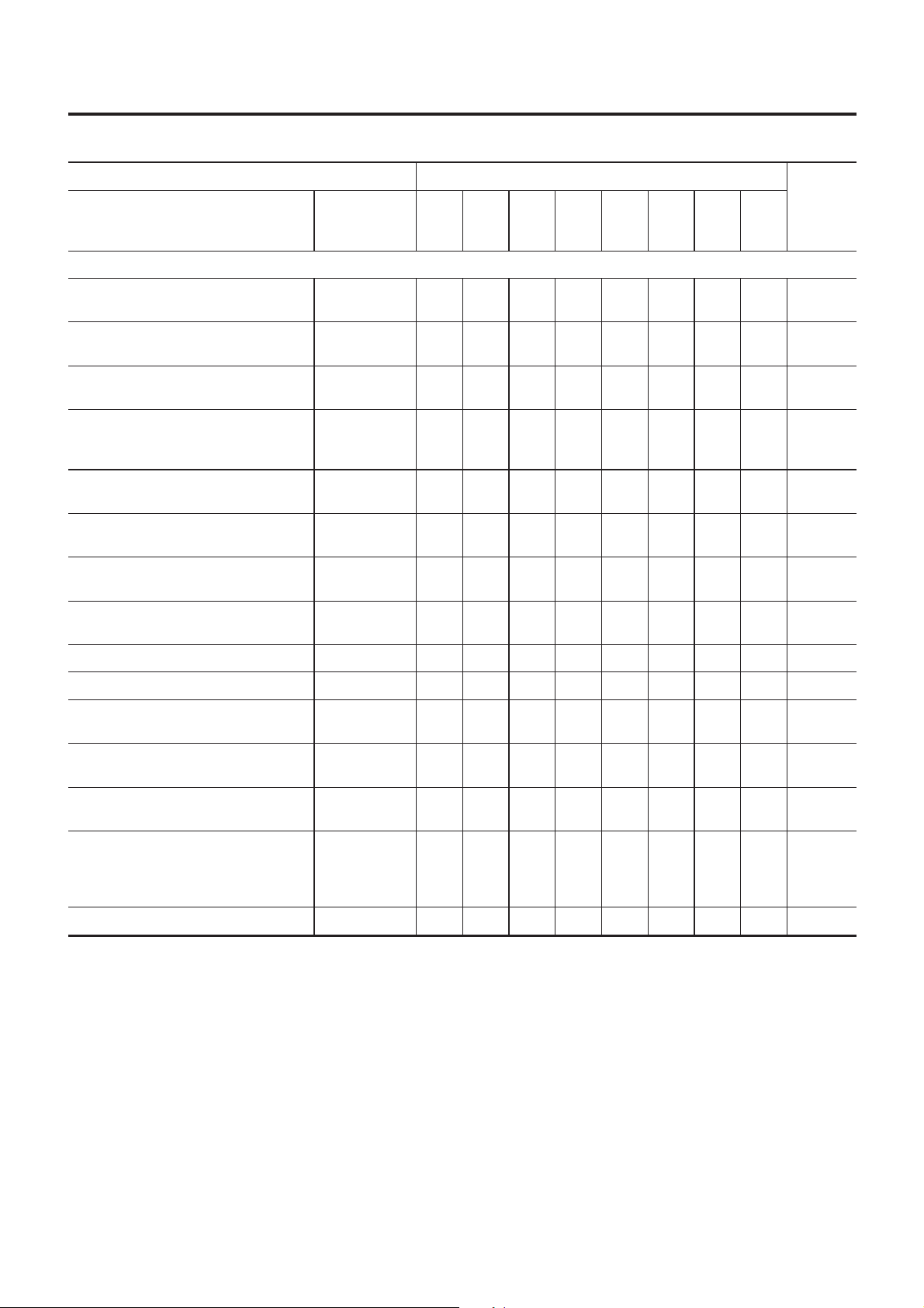
PERIODICMAINTENANCE(FOREUROPE)
Maintenance Schedule for Petrol Engines (Annual Mileage < 30,000 km/year)
Thefollowingtablesshowthenormalmaintenanceschedule.Dependinguponweatherandatmospheric
conditions,varyingroadsurfaces,individualdrivinghabitsandvehicleusage,additionalormorefrequent
maintenancemayberequired.
Periodicmaintenancebeyondthelastperiodshownonthetablesrequiressimilarmaintenance.
MaintenanceScheduleforPetrolEngines
(AnnualMileage<30,000km/year)
VQENGINE
Abbreviations:R=Replace, I=Inspect:Correctorreplaceifnecessary, E=Checkandcorrecttheenginecoolantmixtureratio,
[ ]=Atthespecifiedmileageonly
NFMA0043S01
NFMA0043S0101
MAINTENANCEOPERATION MAINTENANCEINTERVAL
Performonakilometerbasis,buton
anannualbasiswhendrivinglessthan
15,000km(9,000miles)peryear
Engineoil(Userecommendedoil)★ RRRRRRRRMA-21
Engineoilfilter(UseNISSANgenuine
partorequivalent)★
Drivebelts IIIIIIIIMA-15
Coolingsystem IIIIIIIIMA-19
Engineanti-freezecoolant(Usegenu-
ineNISSANAnti-FreezeCoolant(L2N)
orequivalent)
Aircleanerfilter★ R R MA-20
Intakeandexhaustvalveclearance SeeNOTE(2)
FuelandEVAPvapourlines IIII
Sparkplugs Platinum-tippedtype [R] MA-22
Fuelfilter SeeNOTE(3)
kmx1,000
(milesx1,000)
Months
Enginecompartmentandundervehicle
SeeNOTE(1) E MA-16
15
30
45
60
75
(9)
(18)
(27)
12
24
RRRRRRRRMA-21
36
(36)
48
(45)
60
90
(54)
72
105
(63)
84
120
(72)
Refer-
ence
pages
96
EM-51
MA-20/
MA-24
Heatedoxygensensor(Exhaustgas
sensor)★
NOTE:
(1)Firstreplaceat100,000km(60,000miles)/60months,thenevery60,000km(36,000miles)/48months.
(2)Periodicmaintenanceisnotrequired.However,ifvalvenoiseincreases,checkvalveclearance.
(3)Maintenance-freeitem.Forserviceprocedures,refertoFEsection.
(4)Performonlyaccordingto“MaintenanceUnderSevereDrivingConditions”formodelswithoutEuro-OBDsystem.For
modelswithEuro-OBDsystem,periodicmaintenanceisnotrequired.
★Maintenanceitemswith“★”shouldbeperformedmorefrequentlyaccordingto“MaintenanceUnderSevereDrivingCon-
ditions”.
SeeNOTE(4)
MA-24
MA-7
Page 8
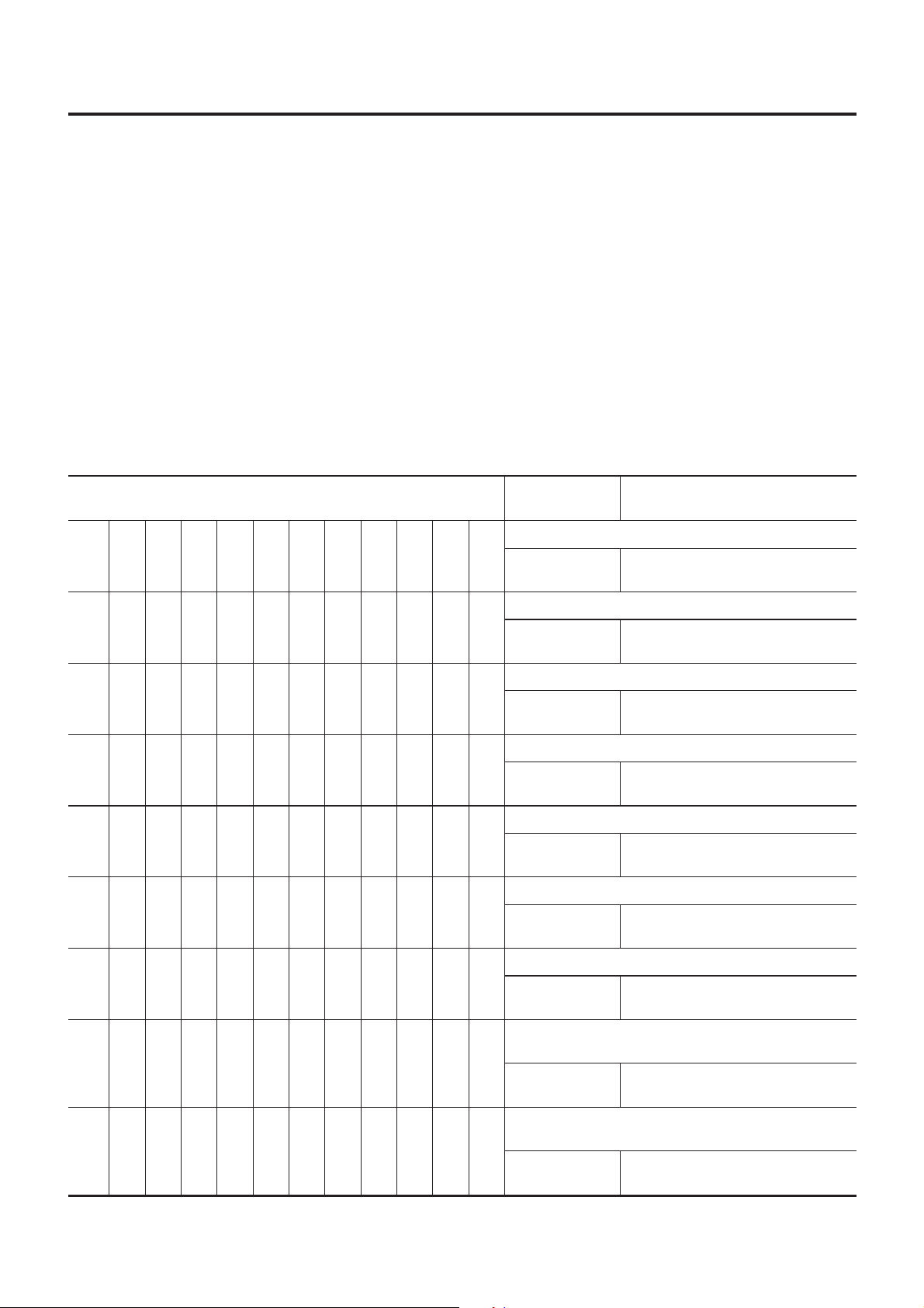
PERIODICMAINTENANCE(FOREUROPE)
Maintenance Schedule for Petrol Engines (Annual Mileage < 30,000 km/year) (Cont’d)
CHASSISANDBODYMAINTENANCE
Abbreviations:R=Replace I=Inspect:Correctorreplaceifnecessary
MAINTENANCEOPERATION MAINTENANCEINTERVAL
Performonakilometerbasis,buton
anannualbasiswhendrivinglessthan
15,000km(9,000miles)inayear.
Headlampaiming IIIIIIII
Wheelalignment(ifnecessary,balance
&rotatewheels)
Brakepads,rotors&otherbrakecomponents★
Footbrake,parkingbrake&clutch(for
freeplay,stroke&operation)
Brakeboostervacuumhoses,
connections,checkvalve
Brake&clutch,systemsandfluid(for
levelandleaks)
Brakefluid★ RRRR
kmx1,000
(milesx1,000)
Months
Underhoodandundervehicle
15
30
45
60
75
(9)
(18)
(27)
12
24
IIIIIIII
IIIIIIIIMA-30
IIIIIIII
IIIIMA-30
IIIIIIII
36
(36)
48
(45)
60
90
(54)
72
105
(63)
84
120
(72)
96
=NFMA0043S0102
Refer-
ence
pages
EL-67
SU-6
MA-27
BR-12
BR-39
MA-25/
MA-29
BR-7
MA-29
/
/
,
Powersteeringfluidandlines(forlevel
andleaks)
ASCDvacuumhoses IIIIIIII
Supplementalairbagsystem SeeNOTE(1)
Ventilationairfilter★ RRRR
Manualtransaxlegearoil(checkfor
leakage).
Automatictransaxlefluid(forleveland
leaks)★
Steeringgear&linkage,axle&suspensionparts,driveshafts,exhaust
system★
Bodycorrosion SeeNOTE(2) MA-32
NOTE:
(1)Inspectatthefirst10years,andthenevery2years.
(2)Inspectonceperyear.
★Maintenanceitemswith“★”shouldbeperformedmorefrequentlyaccordingto“MaintenanceUnderSevereDrivingCon-
ditions”.
IIIIIIIIMA-31
EL-237
RS-14
HA-123
IIIIIIIIMA-25
IIIIIIIIMA-26
MA-25/
IIII
SU-6
SU-20
MA-31
/
/
MA-8
Page 9
PERIODIC MAINTENANCE (FOR EUROPE)
Maintenance Under Severe Driving Conditions (Annual Driving Distance < 30,000 km/year)
Maintenance Under Severe Driving Conditions
(Annual Driving Distance < 30,000 km/year)
The maintenance intervals shown on the preceding pages are for normal operating conditions. If the vehicle
is mainly operated under severe driving conditions as shown below, more frequent maintenance must be performed on the following items as shown in the table.
A — Driving under dusty conditions
B — Driving repeatedly short distances
C — Towing a trailer or caravan
D — Extensive idling
E — Driving in extremely adverse weather conditions or in areas where ambient temperatures are either
extremely low or extremely high
F — Driving in high humidity areas or in mountainous areas
G — Driving in areas using salt or other corrosive materials
H — Driving on rough and/or muddy roads or in the desert
I — Driving with frequent use of braking or in mountainous areas
J — Frequent off road use or driving in water
K — Sustained high speed driving
L — For models without Euro-OBD system
=NFMA0043S03
Driving condition
ABCD........
A...........
...........L
...........L
A...........
.....F......
Maintenance
operation
Engine oil & engine oil filter
Replace
Air cleaner filter
Replace
Front Heated Oxygen Sensor
Inspect
Rear Heated Oxygen Sensor
Inspect
Ventilation air filter
Replace
Brake fluid
Replace
Every 7,500 km (4,500 miles) or 6
months
Every 30,000 km (18,000 miles) or
24 months
Every 30,000 km (18,000 miles) or
24 months
Every 30,000 km (18,000 miles) or
24 months
Every 15,000 km (9,000 miles) or 12
months
Every 15,000 km (9,000 miles) or 6
months
Maintenance interval
..C....H....
A.C...GHI...
......GH....
MA-9
Automatic transaxle fluid
Replace
Brake pads, rotors & other brake system components
Inspect
Steering gear & linkage, axle & suspension parts,
drive shafts, exhaust system
Inspect
Every 30,000 km (18,000 miles) or
24 months
Every 7,500 km (4,500 miles) or 6
months
Every 15,000 km (9,000 miles) or 12
months
Page 10
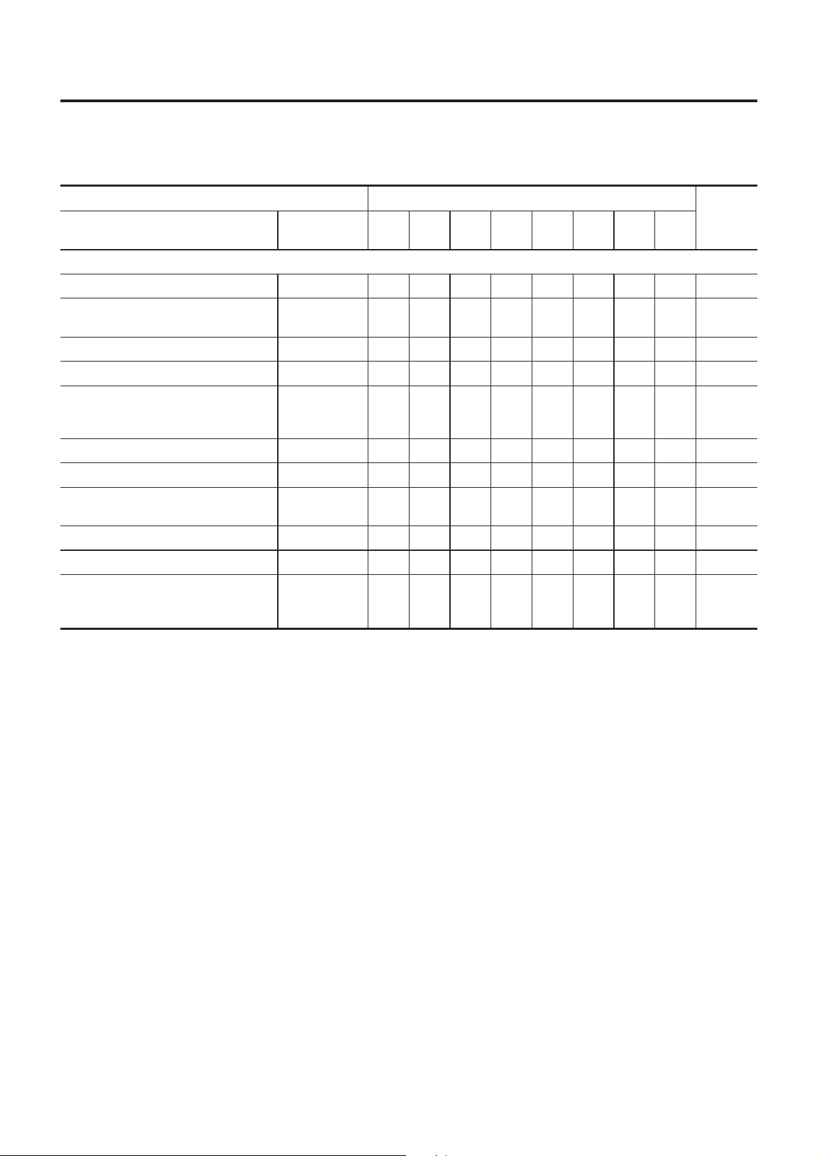
PERIODICMAINTENANCE(FOREUROPE)
Maintenance Schedule for Petrol Engines (Annual Mileage > 30,000 km/year)
MaintenanceScheduleforPetrolEngines
(AnnualMileage>30,000km/year)
VQENGINE
Abbreviations:R=Replace, I=Inspect:Correctorreplaceifnecessary, E=Checkandcorrecttheenginecoolantmixtureratio
=NFMA0043S04
NFMA0043S0401
MAINTENANCEOPERATION MAINTENANCEINTERVAL
Performonakilometerbasisonly.
Engineoil(Userecommendedoil)★ RRRRRRRRMA-21
Engineoilfilter(UseNISSANgenuine
partorequivalent)★
Drivebelts IIIIIIIIMA-15
Coolingsystem IIIIMA-19
Engineanti-freezecoolant(Usegenu-
ineNISSANAnti-FreezeCoolant(L2N)
orequivalent)
Aircleanerfilter★ R R MA-20
Intake&exhaustvalveclearance SeeNOTE(2)
FuelandEVAPvaporlines I I
Sparkplugs Platinum-tippedtype R MA-22
Fuelfilter SeeNOTE(3) R
Heatedoxygensensor(Exhaustgas
sensor)★
kmx1,000
(milesx1,000)15(9)30(18)45(27)60(36)75(45)90(54)
Enginecompartmentandundervehicle
RRRRRRRRMA-21
SeeNOTE(1) E MA-16
SeeNOTE(4)
105
(63)
120
(72)
Refer-
ence
pages
EM-52
MA-20/
MA-24
MA-24
NOTE:
(1)Firstreplaceat100,000km(60,000miles),thenevery60,000km(36,000miles).
(2)Periodicmaintenanceisnotrequired.However,ifvalvenoiseincreases,checkvalveclearance.
(3)Maintenance-freeitem.Forserviceprocedures,refertoFEsection.
(4)Performonlyaccordingto“MaintenanceUnderSevereDrivingConditions”formodelswithoutEuro-OBDsystem.For
modelswithEuro-OBDsystem,periodicmaintenanceisnotrequired.
★Maintenanceitemswith“★”shouldbeperformedmorefrequentlyaccordingto“MaintenanceUnderSevereDrivingCon-
ditions”.
MA-10
Page 11
PERIODICMAINTENANCE(FOREUROPE)
Maintenance Schedule for Petrol Engines (Annual Mileage > 30,000 km/year) (Cont’d)
CHASSISANDBODYMAINTENANCE
Abbreviations:R=Replace I=Inspect:Correctorreplaceifnecessary
MAINTENANCEOPERATION MAINTENANCEINTERVAL
Performonakilometerbasisonly.
Headlampaiming IIII
Wheelalignment(ifnecessary,balance
&rotatewheels)
Brakepads,rotors&otherbrakecomponents★
Footbrake,parkingbrake&clutch(for
freeplay,stroke&operation)
Brakeboostervacuumhoses,
connections,checkvalve
Brake&clutch,systemsandfluid(for
levelandleaks)
Brakefluid★ RR
kmx1,000
(milesx1,000)15(9)30(18)45(27)60(36)75(45)90(54)
Underhoodandundervehicle
IIII
IIIIMA-30
IIII
I I MA-30
IIII
105
(63)
120
(72)
=NFMA0043S0402
Refer-
ence
pages
EL-67
SU-6
/
MA-27
BR-12
/
BR-39
/
MA-25/
MA-29
BR-7
,
MA-29
Powersteeringfluidandlines(forlevel
andleaks)
ASCDvacuumhoses IIII
Supplementalairbagsystem SeeNOTE(1)
Ventilationairfilter★ RRRR
Manualtransaxlegearoil(checkfor
leakage).
Automatictransaxlefluid(forleveland
leaks)★
Steeringgearandlinkage,axle&suspensionparts,driveshafts,exhaust
system★
Bodycorrosion SeeNOTE(2) MA-32
NOTE:
(1)Inspectatthefirst10years,andthenevery2years.
(2)Inspectonceperyear.
★Maintenanceitemswith“★”shouldbeperformedmorefrequentlyaccordingto“MaintenanceUnderSevereDrivingCon-
ditions”.
IIIIMA-31
EL-237
RS-14
HA-123
IIIIMA-25
IIIIMA-26
MA-25/
II
SU-6
SU-20
MA-31
/
/
MA-11
Page 12

PERIODIC MAINTENANCE (FOR EUROPE)
Maintenance Under Severe Driving Conditions (Annual Driving Distance > 30,000 km)
Maintenance Under Severe Driving Conditions
(Annual Driving Distance > 30,000 km)
The maintenance intervals shown on the preceding pages are for normal operating conditions. If the vehicle
is mainly operated under severe driving conditions as shown below, more frequent maintenance must be performed on the following items as shown in the table.
A — Driving under dusty conditions
B — Driving repeatedly short distances
C — Towing a trailer or caravan
D — Extensive idling
E — Driving in extremely adverse weather conditions or in areas where ambient temperatures are either
extremely low or extremely high
F — Driving in high humidity areas or in mountainous areas
G — Driving in areas using salt or other corrosive materials
H — Driving on rough and/or muddy roads or in the desert
I — Driving with frequent use of braking or in mountainous areas
J — Frequent off road use or driving in water
K — Sustained high speed driving
L — For models without Euro-OBD system
=NFMA0043S06
Driving condition
ABCD........
A...........
...........L
...........L
A...........
.....F......
..C....H....
A.C...GHI...
Maintenance
operation
Engine oil & engine oil filter
Replace Every 7,500 km (4,500 miles)
Air cleaner filter
Replace Every 30,000 km (18,000 miles)
Front Heated Oxygen Sensor
Inspect Every 60,000 km (36,000 miles)
Rear Heated Oxygen Sensor
Inspect Every 60,000 km (36,000 miles)
Ventilation air filter
Replace Every 15,000 km (9,000 miles)
Brake fluid
Replace Every 30,000 km (18,000 miles)
Automatic transaxle fluid
Replace Every 60,000 km (36,000 miles)
Brake pads, rotors & other brake system components
Inspect Every 15,000 km (9,000 miles)
Maintenance interval
......GH....
MA-12
Steering gear & linkage, axle & suspension parts,
drive shafts, exhaust system
Inspect Every 30,000 km (18,000 miles)
Page 13

RECOMMENDED FLUIDS AND LUBRICANTS
NFMA0006
Fluids and Lubricants
Fluids and Lubricants
Capacity (Approximate)
Liter Imp qt
Engine oil
(Refill)
With oil filter 4.0 3-1/2 qt
Without oil filter 3.7 3-1/4 qt
LHD 8.5 7-1/2 qt
VQ20
RHD 8.2 7-1/4 qt
LHD 7.7 6-3/4 qt
Cooling
system
With reservoir tank
For Europe
VQ30
RHD 7.4 6-1/2 qt
Reservoir 0.7 (5/8)
7-3/4 -
Manual
transaxle
gear oil
RS5F50A
Oil level L mm (in)
16 - 25 (0.63 - 0.98)
4.5 - 4.8
7-7/8 -
8-1/2 pt*4
RS5F50V 4.25 - 4.55 3-3/4-4qt
Automatic
transaxle
RE4F04B/W 9.4 8-1/4 qt
fluid
Power steering fluid — — Type Dexron
Recommended fluids and lubricants
API SG, SH or SJ*1 for Europe
ILSAC grade GF-I or GF-II*1
Genuine Nissan anti-freeze coolant
(L2N) or equivalent for Europe*3
API GL-4*1
Viscosity SAE 75W-90
Genuine Nissan ATF or equiva-
lent*2
TM
III or equivalent
NFMA0006S01
Brake and clutch fluid — —
DOT 3 or DOT 4 (US FMVSS No.
116)*4
Multi-purpose grease — — NLGI No. 2 (Lithium soap base)
*1: For further details, see “SAE Viscosity Number”.
*2: Contact a Nissandealershipfor more information regarding suitable fluids, including recommended brand(s) ofDexron
TM
III/Mercon
TM
Automatic Transmission Fluid.
*3: Use Genuine Nissan anti-freeze coolant, or equivalent in its quality, in order to avoid possible aluminum corrosion within the engine
cooling system caused by the use of non-genuine engine coolant.
Note that any repairs for the incidents within the engine cooling system while using non-genuine engine coolant may not be
covered by the warranty even if such incidents occurred during the warranty period.
*4: Never mix different types of fluids (DOT 3 and DOT 4).
MA-13
Page 14

SAE Viscosity Number
RECOMMENDED FLUIDS AND LUBRICANTS
Mixed coolant specific gravity
SMA084D
SMA089D
SAE Viscosity Number
=NFMA0006S02
+ For warm and cold areas: 10W-30 is preferable for ambient
temperature above −20°C (−4°F).
5W-30 will positively improve fuel economy.
+ For hot areas: 20W-40 and 20W-50 are suitable.
Engine Coolant Mixture Ratio
NFMA0006S04
The engine cooling system is filled at the factory with a high-quality,
year-round and extended life engine coolant. The high quality
engine coolant contains the specific solutions effective for the anticorrosion and the anti-freeze function. Therefore, additional cooling system additives are not necessary.
CAUTION:
When adding or replacing coolant, be sure to use only Genuine Nissan Anti-freeze Coolant (L2N) or equivalent. Because
L2N is premixed type coolant.
The use of other types of engine coolant may damage your
cooling system.
+ When checking the engine coolant mixture ratio by the coolant
hydrometer, use the chart below to correct your hydrometer
reading (density) according to coolant temperature.
Unit: specific gravity
Engine coolant mixture
ratio
30% 1.046 - 1.050 1.042 - 1.046 1.038 - 1.042 1.033 - 1.038
50% 1.076 - 1.080 1.070 - 1.076 1.065 - 1.071 1.059 - 1.065
Coolant temperature °C (°F)
15 (59) 25 (77) 35 (95) 45 (113)
WARNING:
Never remove the radiator cap when the engine is hot. Serious
burns could be caused by high pressure fluid escaping from
the radiator. Wait until the engine and radiator cool down.
MA-14
Page 15

ENGINE MAINTENANCE
Checking Drive Belts
Checking Drive Belts
NFMA0007
1. Inspect belts for cracks, fraying, wear and oil. If necessary,
replace with a new one.
2. Inspect drive belt deflection at a point on the belt midway
between pulleys.
+ Inspect drive belt deflection when engine is cold.
+ Adjust if belt deflection exceeds the limit or it is not within
specifications.
Belt deflection:
Limit After adjustment
With air conditioner compressor
Alternator
Without air conditioner compressor
Power steering oil pump 11 (0.43)
7 (0.28)
10 (0.39) 6.3 - 6.9 (0.248 - 0.272) 5.6 - 6.0 (0.220 - 0.236)
Deflection adjustment mm (in)
Applied pushing force: 98 N (10 kg, 22 lb)
Used belt
4.2 - 4.6
(0.165 - 0.181)
7.3-8
(0.287 - 0.315)
6.5 - 7.2 (0.256 - 0.283)
SMA804CB
New belt
3.7 - 4.1
(0.146 - 0.161)
MA-15
Page 16

Changing Engine Coolant
ENGINE MAINTENANCE
SMA032D
Changing Engine Coolant
NFMA0008
WARNING:
+ To avoid the danger of being scalded, never change the
coolant when the engine is hot.
+ Wrap a thick cloth around cap and carefully remove the
cap. At first, turn the cap a quarter of a turn to release
built-up pressure. Then turn the cap all the way.
— DRAINING ENGINE COOLANT —
NFMA0008S01
1. Set air conditioning system as follows to prevent coolant from
remaining in the system.
a. Turn ignition switch ON and set temperature controller to maxi-
mum hot position.
b. Wait 10 seconds before turning ignition switch OFF.
2. Open radiator drain plug at the bottom of radiator, and remove
radiator filler cap.
3. Remove reservoir tank, drain coolant, then clean reservoir
tank.
+ Be careful not to allow coolant to contact drive belts.
SMA033D
MA-16
Page 17

ENGINE MAINTENANCE
4. Cover the exhaust tube heat shield to prevent from splashing
coolant.
5. Remove drain plugs on both sides of cylinder block and air
relief plug.
6. Check drained coolant for contaminants such as rust, corrosion or discoloration. If contaminated flush engine cooling
system, refer to “FLUSHING COOLING SYSTEM”, MA-18.
7. Blow the coolant around the exhaust tube heat shield.
SMA034D
Changing Engine Coolant (Cont’d)
SMA953CA
SMA083D
— REFILLING ENGINE COOLANT —
NFMA0008S02
1. Install reservoir tank, and radiator drain plug.
2. Close and tighten cylinder block drain plugs securely.
+ Apply sealant to the thread of cylinder block drain plugs.
Left side:
: 60 - 66 N·m (6.1 - 6.7 kg-m, 44 - 48 ft-lb)
Right side:
: 18 - 22 N·m (1.8 - 2.2 kg-m, 13 - 16 ft-lb)
With oil cooler:
: 25 - 29 N·m (2.5 - 3.0 kg-m, 18 - 21 ft-lb)
3. Fill radiator slowly with coolant until coolant spills from the air
relief plug, then install air relief plug.
Air relief plug:
: 6.9 - 7.8 N·m (0.7 - 0.8 kg-m, 61 - 69 in-lb)
+ Use Nissan genuine engine coolant or equivalent.
MA-17
Page 18

Changing Engine Coolant (Cont’d)
ENGINE MAINTENANCE
Refer to “RECOMMENDED FLUIDS AND LUBRICANTS” for
coolant mixture ratio, MA-14.
Unit: ! (Imp qt)
VQ20DE VQ30DE
LHD RHD LHD RHD
Engine coolant capacity
(With reservoir tank)
8.5 (7-1/2) 8.2 (7-1/4) 7.7 (6-3/4) 7.4 (6-1/2)
SMA182B
SMA412B
Reservoir tank
capacity
0.7 (5/8)
+ Pour coolant through coolant filler neck slowly to allow air
in system to escape.
4. Fill radiator and reservoir tank to specified level.
5. Warm up engine to normal operating temperature without
radiator cap installed.
+ If coolant overflows radiator filler hole, install filler cap.
6. Run engine at 2,500 rpm for 10 seconds and return to idle
speed with radiator cap installed.
+ Repeat two or three times.
Watch coolant temperature gauge so as not to overheat the
engine.
7. Stop engine and cool it down.
+ Cool down using a fan to reduce the time.
+ If necessary, refill radiator up to filler neck with coolant.
8. Refill reservoir tank to MAX level line with coolant.
9. Repeat steps 5 through 8 two or more times with radiator cap
installed until coolant level no longer drops.
10. Check cooling system for leaks with engine running.
11. Warm up engine, and check for sound of coolant flow while
running engine from idle up to 3,000 rpm with heater temperature controller set at several positions between COOL and
WARM.
+ Sound may be noticeable at heater water cock.
12. If sound is heard, bleed air from cooling system by repeating
steps 5 through 8 until coolant level no longer drops
+ Clean excess coolant from engine.
13. Check cooling system for leaks. Refer to MA-20.
— FLUSHING COOLING SYSTEM —
NFMA0008S03
1. Open air relief plug with drain plugs installed.
2. Open coolant passage to heater unit. Refer to step 1 of
“DRAINING ENGINE COOLANT”.
3. Fill radiator with water until water spills from the air relief hole,
then close air relief plug. Fill radiator and reservoir tank with
water and reinstall radiator cap.
4. Run engine and warm it up to until lower radiator hose
becomes warm.
5. Rev engine two or three times under no-load.
Watch coolant temperature gauge so as not to overheat
the engine.
6. Stop engine and wait until it cools down.
+ Cool with a fan to save time
7. Drain water.
MA-18
Page 19

ENGINE MAINTENANCE
Checking Cooling System
8. Repeat steps 1 through 7 until clear water begins to drain from
radiator.
Checking Cooling System
NFMA0037
CAUTION:
Do not remove the thermostat especially on engines with the
thermostat in the water inlet side (radiator lower hose side). If
the thermostat is removed, coolant flow to radiator and coolant pressure in upper radiator hose will be reduced. This will
result in engine overheating.
CHECKING HOSES
NFMA0037S01
Check hoses for improper attachment and for leaks, cracks,
damage, loose connections, chafing and deterioration.
CHECKING RADIATOR
NFMA0037S02
Check radiator for mud or clogging. If necessary, clean radiator as
follows.
+ Be careful not to bend or damage the radiator fins.
+ When radiator is cleaned without removal, remove all sur-
rounding parts such as cooling fan, radiator shroud and horns.
Then tape the harness and connectors to prevent water from
entering.
1. Apply water by hose to the back side of the radiator core vertically downward.
2. Apply water again to all radiator core surfaces once per
minute.
3. Stop washing if any stains no longer flow out from the radiator.
4. Blow air into the back side of radiator core vertically downward.
+ Use compressed air lower than 490 kPa (4.9 bar, 5 kg/cm
2
,71
psi) and keep distance more than 30 cm (11.8 in).
5. Blow air again into all the radiator core surfaces once per
minute until no water sprays out.
NOTE:
For air conditioner equipped models, do the same on the condenser as the above.
SLC613-A
CHECKING RADIATOR CAP
NFMA0037S03
Apply pressure to radiator cap with cap tester to see if it is satisfactory.
Radiator cap relief pressure:
Standard
78 - 98 kPa (0.78 - 0.98 bar, 0.8 - 1.0 kg/cm
2
,11-
14 psi)
Limit
59 - 98 kPa (0.59 - 0.98 bar, 0.6 - 1.0 kg/cm
2
,9-14
psi)
MA-19
Page 20

Checking Cooling System (Cont’d)
ENGINE MAINTENANCE
Pull the negative-pressure valve to open it. Check that it closes
completely when released.
SMA871B
CHECKING COOLING SYSTEM FOR LEAKS
To check for leakage, apply pressure to the cooling system with a
tester.Check that the pressure does not drop for at least 2 minutes.
Testing pressure:
157 kPa (1.57 bar, 1.6 kg/cm
CAUTION:
Higher than the specified pressure may cause radiator damage.
If the pressure drops, check hoses, radiator and water pump
SMA990A
for leaks. If no external leaks are found, check heater core,
cylinder block and cylinder head.
Checking Fuel Lines
Inspect fuel lines and tank for improper attachment, leaks, cracks,
damage, loose connections, chafing or deterioration. If necessary,
repair or replace faulty parts.
2
, 23 psi)
NFMA0037S04
NFMA0009
SMA803A
MMA104A
SMA037D
CAUTION:
Tighten high-pressure rubber hose clamp so that clamp end is
3 mm (0.12 in) from hose end.
Tightening torque specifications are the same for all rubber
hose clamps.
Ensure that screw does not contact adjacent parts.
Changing Air Cleaner Filter
VISCOUS PAPER TYPE
NFMA0011
NFMA0011S01
The viscous paper type filter does not need cleaning.
MA-20
Page 21

ENGINEMAINTENANCE
Changing Engine Oil
SMA038D
ChangingEngineOil
NFMA0012
WARNING:
+ Becarefulnottoburnyourself,astheengineoilishot.
+ Prolongedandrepeatedcontactwithusedengineoilmay
causeskincancer;trytoavoiddirectskincontactwith
usedoil.Ifskincontactismade,washthoroughlywith
soaporhandcleanerassoonaspossible.
1. Warmupengine,andcheckforoilleakagefromenginecomponents.
2. Stopengineandwaitmorethan10minutes.
3. Removedrainplugandoilfillercap.
4. Drainoilandrefillwithnewengineoil.
Oilspecificationandviscosity:
+ Referto“RECOMMENDEDFLUIDSANDLUBRICANTS”,
MA-13.
Oilcapacity(Approximate):
Unit:liter(Impqt)
Withoilfilterchange 4.0(3-1/2)
Drainandrefill
Dryengine(engineoverhaul) 4.2(3-3/4)
Withoutoilfilter
change
3.7(3-1/4)
CAUTION:
+ Besuretocleandrainplugandinstallwithnewwasher.
Oilpandrainplug:
:29-39N·m(3.0-4.0kg-m,22-29ft-lb)
SMA954C
SMA039DA
+ Therefillcapacitydependsontheoiltemperatureand
draintime.Usethesespecificationsforreferenceonly.
Alwaysusethedipsticktodeterminewhentheproper
amountofoilisintheengine.
+ Neverpulloutlevelgaugewhilefillingengineoil.
5. Warmupengineandcheckareaarounddrainplugandoilfilterforoilleakage.
6. Stopengineandwaitmorethan10minutes.
7. Checkoillevel.
ChangingOilFilter
NFMA0013
1. Theoilfilterisasmallfull-flowcartridgetypeandisprovided
withareliefvalve.
LC-6
Referto
, “Oil Filter”.
2. RemoveoilfilterwithToolorsuitabletool.
WARNING:
Becarefulnottoburnyourself,astheengineandtheengine
oilarehot.
MA-21
Page 22
Changing Oil Filter (Cont’d)
ENGINE MAINTENANCE
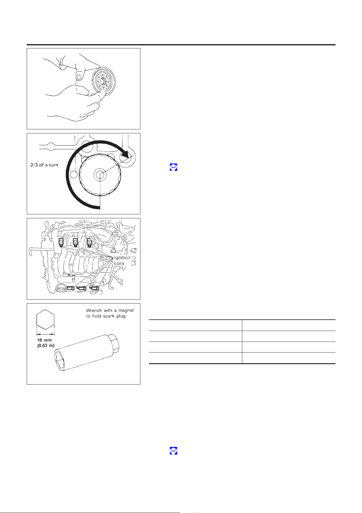
3. Before installing new oil filter, clean oil filter mounting surface
on cylinder block. Coat rubber seal of new oil filter with engine
oil.
SMA010
4. Screw in the oil filter until a slight resistance is felt, then tighten
additionally 2/3 turn.
5. Add engine oil.
Oil filter:
: 14.7 - 20.5 N·m (1.5 - 2.1 kg-m, 11 - 15 ft-lb)
Refer to “Changing Engine Oil”, MA-21.
SMA229B
SMA040D
SEM294A
Changing Spark Plugs (Platinum-tipped Type)
NFMA0014
1. Remove left side rocker cover ornament.
2. Disconnect ignition coil harness connectors.
3. Loosen ignition coil fixing bolts and pull out coil from intake
manifold connector.
4. Remove spark plugs with suitable spark plug wrench.
Spark plug (Platinum-tipped type):
Make NGK
Standard type PFR5G-11
Hot type PFR4G-11
Cold type PFR6G-11
Use standard type spark plug for normal condition.
The hot type spark plug is suitable when fouling may occur with the
standard type spark plug such as:
+ frequent engine starts
+ low ambient temperatures
The cold type spark plug is suitable when spark knock may occur
with the standard type spark plug such as:
+ extended highway driving
+ frequent high engine revolution
Gap (Nominal): 1.1 mm (0.043 in)
: 20 - 29 N·m (2.0 - 3.0 kg-m, 14 - 22 ft-lb)
MA-22
Page 23

ENGINE MAINTENANCE
+ Do not use a wire brush for cleaning.
+ If plug tip is covered with carbon, spark plug cleaner may
be used.
Cleaner air pressure:
Less than 588 kPa (5.9 bar, 6 kg/cm
Cleaning time:
Less than 20 seconds
SMA773C
+ Checking and adjusting plug gap is not required between
removals.
Changing Spark Plugs (Platinum-tipped Type) (Cont’d)
2
, 85 psi)
SMA806C
SEF244Q
Checking Positive Crankcase Ventilation (PCV) System
CHECKING PCV VALVE
With engine running at idle, remove ventilation hose from PCV
valve; if valve is working properly, a hissing noise will be heard as
air passes through it and a strong vacuum should be felt immediately when a finger is placed over valve inlet.
CHECKING VENTILATION HOSES
1. Check hoses and hose connections for leaks.
2. Disconnect all hoses and clean with compressed air. If any
hose cannot be freed of obstructions, replace.
NFMA0035
NFMA0035S01
NFMA0035S02
Checking Vacuum Hose and Connections
NFMA0038
Check vacuum hoses for improper attachment and for leaks,
cracks, damage, loose connections, chafing and deterioration.
MA-23
Page 24

Checking EVAP Vapor Lines
ENGINEMAINTENANCE
SMA082D
CheckingEVAPVaporLines
NFMA0015
1. VisuallyinspectEVAPvaporlinesforimproperattachmentand
forcracks,damage,looseconnections,chafinganddeterioration.
2. Inspectfueltankfillercapvacuumreliefvalveforclogging,
sticking,etc.
EC-32
Referto
CheckingHeatedOxygenSensor(HO2S)
CHECKINGPROCEDURE
Referto
, “Evaporative Emission System”.
EC-179
, “HEATED OXYGEN SENSOR 1 (FRONT)”.
NFMA0039
NFMA0039S01
MA-24
Page 25

CHASSIS AND BODY MAINTENANCE
Checking Exhaust System
SMA211A
SMA941B
Checking Exhaust System
NFMA0016
Check exhaust pipes, muffler and mounting for improper
attachment, leaks, cracks, damage, chafing or deterioration.
Checking Clutch Fluid Level and Leaks
NFMA0017
If fluid level is extremely low, check clutch system for leaks.
Checking Clutch System
NFMA0040
Check fluid lines and operating cylinder for improper attachment,
cracks, damage, loose connections, chafing and deterioration.
SMA450C
SMA066C
SMT512C
Checking M/T Oil
Check for oil leakage and oil level.
Never start engine while checking oil level.
Filler plug:
: 25 - 34 N·m (2.5 - 3.5 kg-m, 18 - 25 ft-lb)
NFMA0018
MA-25
Page 26

Changing M/T Oil
CHASSIS AND BODY MAINTENANCE
SMA067C
SMA053D
SMA051D
Changing M/T Oil
=NFMA0019
1. Drain oil from drain plug and refill with new gear oil.
2. Check oil level.
Oil grade:
API GL-4
Viscosity:
See “RECOMMENDED FLUIDS AND LUBRICANTS”,
MA-13.
Capacity:
See “RECOMMENDED FLUIDS AND LUBRICANTS”,
MA-13.
Drain plug:
: 15 - 20 N·m (1.5 - 2.0 kg-m, 11 - 14 ft-lb)
Checking A/T Fluid
NFMA0020
1. Warm up engine.
2. Check for fluid leakage.
3. Before driving, fluid level can be checked at fluid temperatures
of 30 to 50°C (86 to 122°F) using “COLD” range on A/T fluid
level gauge.
a. Park vehicle on level surface and set parking brake.
b. Start engine and move selector lever through each gear posi-
tion. Leave selector lever in “P” position.
c. Check fluid level with engine idling.
d. Remove A/T fluid level gauge and wipe clean with lint-free
paper.
e. Re-insert A/T fluid level gauge into charging pipe as far as it
will go.
f. Remove A/T fluid level gauge and note reading. If reading is
at low side of range, add fluid to the charging pipe.
Do not overfill.
4. Drive vehicle for approximately 5 minutes in urban areas.
5. Re-check fluid level at fluid temperatures of 50 to 80°C (122
to 176°F) using “HOT” range on A/T fluid level gauge.
CAUTION:
Firmly fix the A/T fluid level gauge to the A/T fluid charging
pipe using a stopper attached.
MA-26
Page 27

CHASSISANDBODYMAINTENANCE
6. Checkfluidcondition.
+ Iffluidisverydarkorsmellsburned,refertoATsectionfor
checkingoperationofA/T.Flushcoolingsystemafterrepairof
A/T.
+ IfA/Tfluidcontainsfrictionalmaterial(clutches,bands,etc.),
replaceradiatorandflushcoolerlineusingcleaningsolvent
andcompressedairafterrepairofA/T.Referto
tor”.
SMA853B
Checking A/T Fluid (Cont’d)
LC-18
, “Radia-
SMA052D
ChangingA/TFluid
NFMA0021
1. WarmupA/Tfluid.
2. Stopengine.
3. DrainA/TfluidfromdrainplugandrefillwithnewA/Tfluid.
Alwaysrefillsamevolumewithdrainedfluid.
Fluidgrade:
GenuineNissanATForequivalent
Refer to “RECOMMENDED FLUIDS AND
LUBRICANTS”,MA-13.
Fluidcapacity(Withtorqueconverter):
RE4F04B/RE4F04W
9.4!(8-1/4Impqt)
Drainplug:
:29-39N·m(3.0-4.0kg-m,22-29ft-lb)
4. Runengineatidlespeedforfiveminutes.
5. Checkfluidlevelandcondition.Referto“CheckingA/TFluid”.
Iffluidisstilldirty,repeatstep2.through5.
BalancingWheels(BondingWeightType)
REMOVAL
NFMA0022
NFMA0022S01
1. Removeinnerandouterbalanceweightsfromtheroadwheel.
CAUTION:
Becarefulnottoscratchtheroadwheelduringremovalprocedures.
2. Usingreleasingagent,removedouble-facedadhesivetape
fromtheroadwheel.
CAUTION:
+ Becarefulnottoscratchtheroadwheelduringremoval.
+ Afterremovingdouble-facedadhesivetape,wipeclean
tracesofreleasingagentfromtheroadwheel.
WHEELBALANCEADJUSTMENT
NFMA0022S02
+ Ifatirebalancemachinehasadhesionbalanceweightmode
settingsanddrive-inweightmodesetting,selectandadjusta
drive-inweightmodesuitableforroadwheels.
1. Setroadwheelonwheelbalancerusingthecenterholeasa
guide.Startthetirebalancemachine.
2. Wheninnerandouterunbalancevaluesareshownonthe
wheelbalancerindicator,multiplyouterunbalancevalueby1.6
todeterminebalanceweightthatshouldbeused.Selectthe
outerbalanceweightwithavalueclosesttothecalculated
MA-27
Page 28

CHASSIS AND BODY MAINTENANCE
Balancing Wheels (Bonding Weight Type) (Cont’d)
value above and install it to the designated outer position of,
or at the designated angle in relation to the road wheel.
CAUTION:
+ Do not install the inner balance weight before installing
the outer balance weight.
+ Before installing the balance weight, be sure to clean the
mating surface of the road wheel.
Indicated unbalance value × 1.6 = balance weight to be
installed
Calculation example:
23 g (0.81 oz) × 1.6 = 38.33 g (1.35 oz) = 40 g (1.41 oz) balance weight (closer to calculated balance weight value)
Note that balance weight value must be closer to the calculated balance weight value.
Example:
37.4 = 35 g (1.23 oz)
37.5 = 40 g (1.41 oz)
SMA054D
SMA055DA
SMA056D
a. Install balance weight in the position shown in the figure at left.
b. When installing balance weight to road wheels, set it into the
grooved area on the inner wall of the road wheel as shown in
the figure at left so that the balance weight center is aligned
with the wheel balancer indication position (angle).
CAUTION:
+ Always use genuine Nissan adhesion balance weights.
+ Balance weights are unreusable; always replace with new
ones.
+ Do not install more than three sheets of balance weight.
c. If calculated balance weight value exceeds 50 g (1.76 oz),
install two balance weight sheets in line with each other (as
shown in the figure at left).
CAUTION:
Do not install one balance weight sheet on top of another.
3. Start wheel balancer again.
4. Install drive-in balance weight on inner side of road wheel in
the wheel balancer indication position (angle).
CAUTION:
Do not install more than two balance weights.
5. Start wheel balancer. Make sure that inner and outer residual
MA-28
Page 29

CHASSISANDBODYMAINTENANCE
Balancing Wheels (Bonding Weight Type) (Cont’d)
unbalancevaluesare10g(0.35oz)eachorbelow.
+ Ifeitherresidualunbalancevalueexceeds10g(0.35oz),
repeatinstallationprocedures.
Wheelbalance(Maximumallowableunbalance):
SMA829C
Maximumallowable
unbalance
TireRotation
Dynamic(Atrimflange) 10g(0.35oz)(oneside)
Static 20g(0.71oz)
NFMA0023
+ DonotincludetheT-typesparetirewhenrotatingthe
tires.
+ Afterrotatingthetires,adjustthetirepressure.
+ Retightenthewheelnutswhenthevehiclehasbeen
drivenfor1,000km(600miles)(alsoincasesofaflattire,
etc.).
Wheelnuts:
:98-118N·m(10.0-12.0kg-m,72-87ft-lb)
CheckingBrakeFluidLevelandLeaks
NFMA0024
Iffluidlevelisextremelylow,checkbrakesystemforleaks.
SBR451D
SBR389C
SBR404C
CheckingBrakeLinesandCables
NFMA0025
Checkbrakefluidlinesandparkingbrakecablesforimproper
attachment,leaks,chafing,abrasions,deterioration,etc.
ChangingBrakeFluid
NFMA0041
1. Drainbrakefluidfromeachairbleedervalve.
2. Refilluntilnewbrakefluidcomesoutfromeachairbleeder
valve.
Usesameprocedureasinbleedinghydraulicsystemtorefill
brakefluid.
Referto
BR-8
, “Bleeding Brake System”.
+ Refillwithrecommendedbrakefluid.
See“RECOMMENDEDFLUIDSANDLUBRICANTS”.
+ Neverreusedrainedbrakefluid.
+ Becarefulnottosplashbrakefluidonpaintedareas.
MA-29
Page 30

CHASSIS AND BODY MAINTENANCE
Checking Brake Booster, Vacuum Hoses, Connections and Check Valve
Checking Brake Booster, Vacuum Hoses,
Connections and Check Valve
Check vacuum lines, connections and check valve for improper
attachment, air tightness, chafing and deterioration.
NFMA0042
SMA260A
Checking Disc Brake
ROTOR
Check condition and thickness.
Unit: mm (in)
Front Rear
Brake model CLZ25VC CL9HB
Standard thickness 26 (1.02) 9 (0.35)
Maximum runout 0.07 (0.0028) 0.07 (0.0028)
Minimum thickness
(Wear limit)
CALIPER
Check for leakage.
24.0 (0.945) 8.0 (0.315)
NFMA0026
NFMA0026S01
NFMA0026S02
SMA922A
SMA847B
PAD
Check for wear or damage.
Unit: mm (in)
Brake model CLZ25VC CL9HB
Standard thickness 11 (0.43) 10 (0.39)
Minimum thickness
(Wear limit)
2.0 (0.079) 1.5 (0.059)
MA-30
NFMA0026S03
Page 31

CHASSIS AND BODY MAINTENANCE
Checking Steering Gear and Linkage
SMA654C
SST850C
Checking Steering Gear and Linkage
STEERING GEAR
NFMA0027
NFMA0027S01
+ Check gear housing and boots for looseness, damage and
grease leakage.
+ Check connection with steering column for looseness.
STEERING LINKAGE
NFMA0027S02
Check ball joint, dust cover and other component parts for
looseness, wear, damage and grease leakage.
Checking Power Steering Fluid and Lines
NFMA0028
Check fluid level in reservoir tank with engine off.
Use “HOT” range at fluid temperatures of 50 to 80°C(122 to 176°F)
or “COLD” range at fluid temperatures of 0 to 30°C (32 to 86°F).
CAUTION:
+ Do not overfill.
TM
+ Recommended fluid is type Dexron
III or equivalent.
Refer to “RECOMMENDED FLUIDS AND LUBRICANTS”,
MA-13.
+ Check lines for improper attachment, leaks, cracks, damage,
loose connections, chafing and deterioration.
+ Check rack boots for accumulation of power steering fluid.
SST851C
Lubricating Locks, Hinges and Hood Latches
NFMA0029
SMA081D
MA-31
Page 32
CHASSIS AND BODY MAINTENANCE
Checking Seat Belts, Buckles, Retractors, Anchors and Adjusters
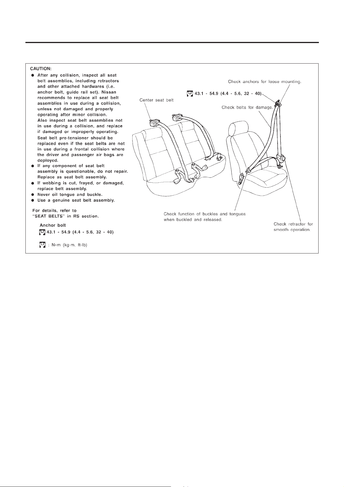
Checking Seat Belts, Buckles, Retractors,
Anchors and Adjusters
NFMA0030
SMA042DA
Checking Body Corrosion
NFMA0044
Visually check body panels for corrosion, paint damage (scratches,
chipping, rubbing, etc.) or damage to the anti-corrosion materials.
In particular, check the following locations.
Hemmed panels
Hood front end, door lower end, trunk lid rear end, etc.
Panel joint
Side sill of rear fender and center pillar, rear wheel housing of rear
fender, around strut tower in engine compartment, etc.
Panel edge
Trunk lid opening, sunroof opening, fender wheel-arch flange, fuel
filler lid flange, around holes in panel, etc.
Parts contact
Waist moulding, windshield moulding, bumper, etc.
Protectors
Damage or condition of mudguard, fender protector, chipping
protector, etc.
Anti-corrosion materials
Damage or separation of anti-corrosion materials under the body.
Drain holes
Condition of drain holes at door and side sill.
When repairing corroded areas, refer to the Corrosion Repair
Manual.
MA-32
Page 33

SERVICE DATA AND SPECIFICATIONS (SDS)
Engine Maintenance
BELT DEFLECTION AND TENSION
Deflection adjustment
mm (in)
Used belt
Limit After adjustment
With air conditioner compressor 7 (0.28)
Alternator
Power steering oil pump 11 (0.43)
Applied pushing force 98 N (10 kg, 22 lb)
Without air conditioner compressor
10 (0.39)
4.2 - 4.6
(0.165 - 0.181)
6.3 - 6.9
(0.248 - 0.272)
7.3-8
(0.287 - 0.315)
Engine Maintenance
NFMA0031
New belt
3.7 - 4.1
(0.146 - 0.161)
5.6 - 6.0
(0.220 - 0.236)
6.5 - 7.2
(0.256 - 0.283)
SPARK PLUG (PLATINUM-TIPPED TYPE)
Make NGK
Standard PFR5G-11
Hot PFR4G-11
Type
Cold PFR6G-11
Plug gap mm (in) 1.1 (0.043) (Nominal)
Chassis and Body Maintenance
WHEEL BALANCE
Dynamic (At rim flange) 10 g (0.35 oz) (one side)
Maximum allowable unbalance
Static 20 g (0.71 oz)
NFMA0032
NFMA0033
MA-33
Page 34

Note
SERVICE DATA AND SPECIFICATIONS (SDS)
Note
MA-34
 Loading...