

The NISSAN GT-R, introducing you
Information Provided by:
to a new genre of supercars
The legend of the GT-R began in May of 1964 in Japan when the affectionately termed “boxy” Skyline passed a Porsche 904 at a hairpin curve on the
Suzuka Circuit.
The GT-R legend continued on the Japanese racing circuits and in the sports car world when the GT-R was equipped with a powerful engine and state-ofthe-art all-wheel drive system in August of 1989.
A new legend is in the making for the 21st century. The “NISSAN GT-R” is now available worldwide.
During development, the NISSAN GT-R was taken to the Nurburgring in Germany, a racetrack used for performance evaluation benchmarking of
supercars. While being driven by a professional driver, the GT-R set a record time of 7 minutes 38 seconds even though the road surface of the most
difficult high-speed corner, the “kesselchen” was wet. The GT-R also handled an endurance test totaling approximately 3,000 miles (5,000 km), setting
the world’s fastest continuous driving lap time of 7 minutes 55 seconds. Additionally, to make sure the GT-R performs off the track as well as it does on the
track, the vehicle was designed to perform on many types of roads from a scorching freeway to snow swept country roads.
A new legend is born.
Information Provided by:
Foreword
Information Provided by:
Welcome to the growing family of new NISSAN
owners. This vehicle is delivered to you with
confidence. It was produced using the latest
techniques and strict quality control.
This manual was prepared to help you understand the operation and maintenance of your
vehicle so that you may enjoy many miles
(kilometers) of driving pleasure. Please read
through this manual before operating your
vehicle.
A separate Warranty Information Booklet
contains the warranties c overing your
vehicle (whose terms have control over
this Owner’s Manual or any other document or representation regarding warranty
coverage). The “NISSAN Service and Maintenance Guide” explains details about
maintaining and servicing your vehicle.
Additionally, a separate Customer Care/
Lemon Law Booklet (U.S. only) will explain
how to resolve any concerns you may have
with your vehicle, as well as clarify your
rights under your state’s lemon law.
Your NISSAN dealership knows your vehicle best. When you require any service or
have any questions, they will be glad to
assist you with the extensive resources
available to them.
READ FIRST — THEN DRIVE SAFELY
Before driving your vehicle, please read this
Owner’s Manual carefully. This will ensure
familiarity with controls and maintenance requirements, assisting you in the safe operation
of your vehicle.
WARNING
IMPORTANT SAFETY INFORMATION
REMINDERS FOR SAFETY!
Follow these important driving rules to
help ensure a safe and comfortable trip
for you and your passengers!
. NEVER drive under the influence of
alcohol or drugs.
. ALWAYS observe posted speed lim-
its and never drive too fast for
conditions.
. ALWAYS give your full attention to
driving and avoid using vehicle
features or taking other actions that
could distract you.
. ALWAYS use your seat belts and
appropriate child restraint systems.
Pre-teen children should be seated
in the rear seat.
. ALWAYS provide information about
the proper use of vehicle safety
features to all occupants of the
vehicle.
. ALWAYS review this Owner’s Man-
ual for important safety information.
MODIFICATION OF YOUR VEHICLE
This vehicle should not be modified. Modification could affect its performance,
safety or durability, and may even violate
governmental regulations. See the 2009
Nissan GT-R Warranty Information Booklet
for details including applicable exclusions.
WHEN READING THE MANUAL
This manual includes information for all
options available on this model. Therefore,
you may find some information that does
not apply to your vehicle.
All information, specifications and illustrations in
this manual are those in effect at the time of
printing. NISSAN reserves the right to change
specifications or design at any time without
notice.
IMPORTANT INFORMATION ABOUT
Information Provided by:
THIS MANUAL
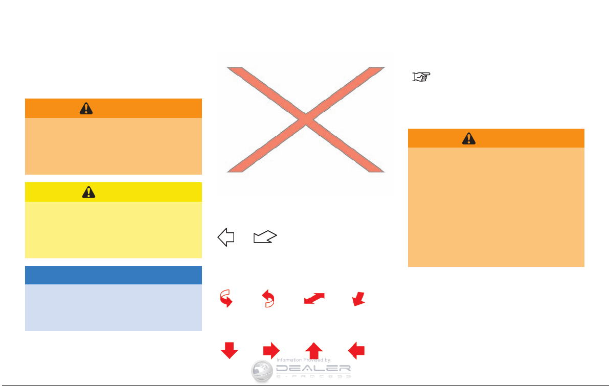
You will see various symbols in this manual. They
are used in the following ways:
WARNING
This is used to indicate a hazard that
could cause death or serious personal
injury. To avoid or reduce the risk,
follow the information and instructions
exactly.
CAUTION
This is used to indicate a hazard that
could cause minor or moderate personal injury. To avoid or reduce the risk,
follow the information and instructions
carefully.
NOTICE
This is used to indicate a hazard that
could cause damage to property or your
vehicle. To avoid or reduce the risk,
follow the information and instructions.
If you see the symbol above, it means “Do not
do this” or “Do not let this happen”.
If you see a symbol similar to those above in an
illustration, it means the arrow points to the front
of the vehicle.
Arrows in an illustration that are similar to those
above indicate movement or action.
Arrows in an illustration that are similar to those
above call attention to an item in the illustration.
This indicates the title and reference page.
CALIFORNIA PROPOSITION 65
WARNING
WARNING
Engine Exhaust, some of its constituents, and certain vehicle components
contain or emit chemicals known to the
State of California to cause cancer and
birth defects or other reproductive
harm. In addition, certain fluids contained in vehicles and certain products
of component wear contain or emi t
chemicals known to the State of California to cause cancer and birth defects
or other reproductive harm.
CALIFORNIA PERCHLORATE ADVISORY
Some vehicle parts, such as lithium batteries, may contain perchlorate material.
The following advisory is provided: “Perchlorate Material - special handling may
apply, See www.dtsc.ca.gov/
hazardouswaste/perchlorate.”

C
Information Provided by:
*
2008 NISSAN MOTOR CO., LTD.
All rights reserved. No part of this Owner’s
Manual may be reproduced or stored in a
retrieval system, or transmitted in any form, or
by any means, electronic, mechanical, photocopying, recording or otherwise, without the
prior written permission of NISSAN Motor Co.,
Ltd.

NISSAN CUSTOMER CARE PROGRAM
Information Provided by:
NISSAN CARES ...
Both NISSAN and your GT-R certified NISSAN dealer are dedicated to serving all your automotive needs. Your satisfaction with your vehicle and your
GT-R certified NISSAN dealer are our primary concerns. Your GT-R certified NISSAN dealer is always available to assist you with all your automobile sales
and service needs.
However, if there is something that your GT-R
certified NISSAN dealer cannot assist you with
or you would like to provide NISSAN directly
with comments or questions, please contact the
NISSAN Consumer Affairs Department using
our toll-free number:
For U.S. customers
1-866-668-1GTR
(1-866-668-1487)
For Canadian customers
1-800-387-0122
We appreciate your interest in NISSAN and thank you for buying a quality NISSAN vehicle.
The Consumer Affairs Department will ask for
the following information:
— Your name, address, and telephone number
— Vehicle identification number (attached to
the top of the instrument panel on the
driver’s side)
— Date of purchase
— Current odometer reading
— Your NISSAN dealer’s name
— Your comments or questions
OR
You can write to NISSAN with the information on
the left at:
For U.S. customers
NISSAN North America, Inc.
Consumer Affairs Department
P.O. Box 685003
Franklin, TN 37068-5003
For Canadian customers
NISSAN Canada Inc.
5290 Orbitor Drive
Mississauga, Ontario L4W 4Z5
Table of
Information Provided by:
GT-R Overview
GTR
Contents
Illustrated table of contents
Safety — Seats, seat belts and supplemental restraint system
Instruments and controls
Pre-driving checks and adjustments
Display screen, heater, air conditioner and audio systems
Starting and driving
In case of emergency
Appearance and care
Maintenance and do-it-yourself
Technical and consumer information
Index
0
1
2
3
4
5
6
7
8
9
10
GT-R Overview
Information Provided by:
GT-R specific information .................................GTR-2
GT-R special specification parts ........................GTR-2
GT-R performance optimization services .............. GTR-4
Precautions before driving ................................ GTR-5
Body repair................................................... GTR-5
Warranty information ................................... GTR-2
Maintenance information ..............................GTR-2
Engine oil ................................................. GTR-2
Transmission oil ......................................... GTR-2
Differential oil (front and rear)........................ GTR-2
Brake fluid ................................................ GTR-3
Tires and road wheels ................................. GTR-3
Brake pad and disc rotor .............................GTR-3
Exhaust muffler .......................................... GTR-3
Exterior parts (spoiler, etc.)........................... GTR-3
Wheel alignment inspection and adjustment
(if necessary) (including tire pressure
adjustment)............................................... GTR-4
Engine settings (balancing right and left
air flow) ...................................................GTR-4
Transmission settings .................................. GTR-4
Vehicle Dynamic Control (VDC) off mode ........ GTR-5
Summer tires ............................................ GTR-5
All-season tires.......................................... GTR-5
Additional maintenance items ............................ GTR-6
Fluids ...................................................... GTR-6
Inspection and adjustments of tires, suspension
and brakes ...............................................GTR-6
Replenishing coolant................................... GTR-6
Coolant mixture ratio ................................... GTR-7
Cool down ............................................... GTR-7
GT-R specific vehicle characteristics................... GTR-7
Refueling precautions.................................. GTR-7
Refueling stops before the tank is full ............. GTR-7
Gasoline smell........................................... GTR-7
Outside temperature display indicates higher
temperature .............................................. GTR-7
Idle speed is not steady............................... GTR-7
Engine speed is restricted ............................GTR-7
Distortion of rear wing................................. GTR-8
Uneven wear of tires ................................... GTR-8
Noises are heard while driving....................... GTR-8
Brake dust................................................ GTR-9
Mechanical Limited Slip Differential (LSD)
characteristics ...........................................GTR-9
Dual clutch transmission ..................................GTR-9
Transmission operation characteristics........... GTR-10
GT-R SPECIFIC INFORMATION
Information Provided by:
The GT-R is NISSAN’s first supercar category
vehicle. The GT-R is equipped with special
systems. These systems are different than those
used on conventional vehicles to allow for the
high performance driving characteristics of this
vehicle. Your vehicle should be maintained by a
GT-R certified NISSAN dealer. Special skills,
knowledge and equipment are necessary to
properly maintain your GT-R.
WARRANTY INFORMATION
Please read this OM carefully, together with your
Warranty Information Booklet which describes a
number of express limitations and exclusions for
failure to follow the instructions contained in this
OM, including, but not limited to:
. Failure to use proper parts, fuel and fluids,
. Driving with the VDC off,
. Racing,
. Modifications, including reprogramming or
replacing/adding chips in any on-board
computer,
. Failure to have required Performance Opti-
mization Services performed.
In addition, see your Dunlop/Goodyear and
Bridgestone tire warranties for specific limitations or exclusions for operating summer tires
below −48F(−208C).
GTR-2 GT-R Overview
MAINTENANCE INFORMATION
. Special skills, knowledge and equipment are
necessary to properly inspect and adjust the
GT-R engine, transmission, suspension and
brakes to maintain performance. A GT-R
certified NISSAN dealer has the GT-R
certified technical staff and the special
equipment to properly maintain your GT-R.
. Many general periodic maintenance items
can be performed at all NISSAN dealers.
However, make sure the specified fluids and
parts are used when the maintenance is
performed.
GT-R SPECIAL SPECIFICATION
PARTS
Only use the following required fluids and parts
in the GT-R.
ENGINE OIL
Mobil 1, 0W-40 (100% synthetic oil)
Mobil 1, 0W-40 (100% synthetic) is the factory
fill oil. The VR38 engine with its plasma-sprayed
bores was developed using this oil. NISSAN
cannot ensure proper engine operation and
durability if other 0W-40 synthetic oil is used.
If Mobil 1, 0W-40 is not available, Mobil 1,
10W-40 (100% synthetic) may be used; however, some performance loss may be noticed.
TRANSMISSION OIL
Genuine NISSAN Transmission Oil R35
Special (100% synthetic oil)
The GT-R uses a multiple-disc dual wet clutch
transmission. The specially developed transmission oil maximizes the friction characteristics of
the clutch and the lubrication of the gear
bearings. The use of additives is prohibited.
DIFFERENTIAL OIL (front and rear)
Castrol SAF-XJ 75W-140 (100% synthetic
oil)
The GT-R uses a 1.5-Way mechanical Limited
Slip Differential (LSD) to maximize driving power
under many operating conditions. Use the
specified differential oil to maximize the perfor-
mance of the LSD. Also use the same oil for the
Information Provided by:
front differential. The use of additives is
prohibited.
BRAKE FLUID
Genuine NISSAN Brake Fluid R35 Special
DOT4
Genuine NISSAN Brake Fluid R35 Special
DOT4 is the factory fill brake fluid. The Vehicle
Dynamic Control (VDC) unit and other related
parts were specially designed for this brake
fluid. NISSAN cannot ensure the best performance and proper operation of the vehicle if
other brake fluid is used.
TIRES AND ROAD WHEELS
Genuine GT-R tires and road wheels or
equivalent
Use only genuine GT-R tires and road wheels or
equivalent. Proper use of NISSAN recommended tires provides the greatest potential
for maximum performance.
. Genuine GT-R tires and road wheels or an
equivalent help achieve maximum cornering
performance.
. Genuine GT-R tires and road wheels or an
equivalent help provide road holding in the
event of decreasing tire pressure and
punctures.
. Genuine GT-R tires and road wheels or an
equivalent help prevent the decrease of
straight-running stability caused by uneven
tire wear due to high rigidity wheels and
wide tires.
BRAKE PAD AND DISC ROTOR
Genuine GT-R brake pads and disc rotors
This vehicle is equipped with a high performance braking system and includes crossdrilled floating rotors and radial-mounted sixpiston monoblock calipers. This helps to achieve
excellent stopping performance and fade-resistance. Replace all four sets of brake pads and
disc rot ors at the same time to maintain
maximum brake performance.
EXHAUST MUFFLER
Use only the special GT-R muffler and
trunk carpet.
Never use parts other than genuine NISSAN
parts.
The GT-R has high exhaust gas temperatures. If
non-GT-R specification parts are used, it is
possible that the muffler will deform and cause
damage to the underbody. Also do not remove
the trunk carpet from the vehicle for any reason.
The carpet insulates the vehicle interior from the
heat of the muffler and from the noise of the
transmission.
EXTERIOR PARTS (spoiler, etc.)
Do not modify exterior parts.
The GT-R was developed using a special wind
tunnel to help make sure the vehicle is
aerodynamically balanced. Additionally, the wind
tunnel was used to help make sure cool air flows
to the brakes, radiator and other components.
Additions of non-GT-R specific accessory exterior parts can change the air flow over and
around the body. This can affect vehicle balance
and cooling of various systems.
For example, if the front bumper is modified,
there is a possibility that brake performance may
be reduced due to the decrease of the air flow to
the brake system.
GT-R Overview GTR-3

GT-R PERFORMANCE
Information Provided by:
OPTIMIZATION SERVICES
In addition to the regular maintenance recommended by NISSAN, the GT-R requires the
following special inspections:
. Wheel alignment inspection and adjustment
(if necessary) (including tire pressure adjustment)
. Engine settings (balancing right and left air
flow)
. Transmission settings
These inspections are required at the following
intervals:
. 1,000 miles
. 12 months
. 24 months
. 36 months
NOTE:
. These inspections will be performed
free of charge for labor at a GT-R
certified NISSAN dealer only. Inspections thereafter are recommended
every 12 months or 12,000 miles
(whichever comes first) at the customer’s expense. See the 2009 NISSAN
GT-R Warranty Information Booklet for
details.
. Repairs and adjustments involving
GTR-4 GT-R Overview
parts replacement, etc. determined to
be necessary as a result of these
inspections are performed at the customer’s expense.
. See the 2009 NISSAN GT-R Warranty
Information Booklet for significant limitations, exclusions and possible voiding of your warranty resulting from
failure to have these necessary inspections, repairs and/or adjustments performed.
. See the 2009 NISSAN GT-R Service and
Maintenance Guide for a detailed explanation of the GT-R Performance
Optimization services.
WHEEL ALIGNMENT INSPECTION
AND ADJUSTMENT (if necessary)
(including tire pressure adjustment)
This vehicle is equipped with a high performance suspension. The vehicle’s wheel alignment needs to be measured and adjusted (if
necessary) by a GT-R certified NISSAN dealer
as necessary as the vehicle is driven and the
suspension parts break-in.
ENGINE SETTINGS (balancing right
and left air flow)
Each cylinder bank of this engine operates
independently due to the vehicle’s twin turbocharger design. Each side of the engine must
operate at the same level of performance. The
power output of each bank must be checked
and adjusted as necessary by a GT-R certified
NISSAN dealer.
TRANSMISSION SETTINGS
The design of the clutch and transmission
requires inspection and adjustment of the clutch
and shift forks by a GT-R certified NISSAN
dealer at the recommended intervals. Depending on the driving conditions, more frequent
adjustments may be necessary to help maximize
vehicle performance.
PRECAUTIONS BEFORE DRIVING BODY REPAIR
Information Provided by:
VEHICLE DYNAMIC CONTROL (VDC)
OFF MODE
Make sure VDC is on before driving the vehicle.
The VDC OFF mode should only be used to help
free a vehicle stuck in mud or snow by
temporarily stopping VDC operation and keeping torque on wheels.
SUMMER TIRES
The GT-R summer tires are made from a
specially formulated rubber t o maximize the
vehicle’s performance capabilities. Performance
of summer tires is substantially reduced when
temperatures are less than 328F(08C) so you
must drive carefully. NISSAN recommends the
use of winter or all-season tires on all four
wheels if you plan to operate your vehicle in
snowy or icy conditions when temperatures are
less than 328F(08C).
ALL-SEASON TIRES
Do not exceed the speed rating of the tire that is
installed on the vehicle.
The body of the GT-R has been manufactured
on special fixtures utilizing a hybrid structure
with aluminum die cast parts for the frame work.
Special skills, information and equipment are
required to correctly repair the body. Contact a
GT-R certified NISSAN dealer if the vehicle is
damaged, such as in a collision, and they will
recommend an appropriate body shop.
Only certified body shops using CELETTE
advanced collision repair equipment are approved by NISSAN for repairing structural body
damage. Contact a GT-R certified NISSAN
dealer or NISSAN Consumer Affairs for a
referral or list of certified body shops.
WARNING
Never use summer tires when the
temperature is below −48F(−208C) to
prevent permanent tread deformation
which may cause tire damage or tire
failure. This may cause a loss of vehicle
control which can resul t in serious
personal injury or death.
®
GT-R Overview GTR-5
ADDITIONAL MAINTENANCE ITEMS
Information Provided by:
The following information applies if you engage
in performance driving such as driving your
GT-R for extended periods under the following
conditions.
. Higher-RPM (approaching redline) opera-
tion
. Frequent high pedal force bra king from
moderate and higher speeds
. Frequent throttle activation
. Fast revving throughout the RPM range
In such cases, the following additional maintenance guidelines apply.
However, you should also carefully read
your 2009 NISSAN GT-R Warranty Information Booklet for important information
concerning warranty coverage, limitations
and exclusions.
We recommend that maintenance be performed
at a GT-R certified NISSAN dealer. NISSAN will
only pay for GT-R Performance Optimization
Services performed at a GT-R certified NISSAN
dealer.
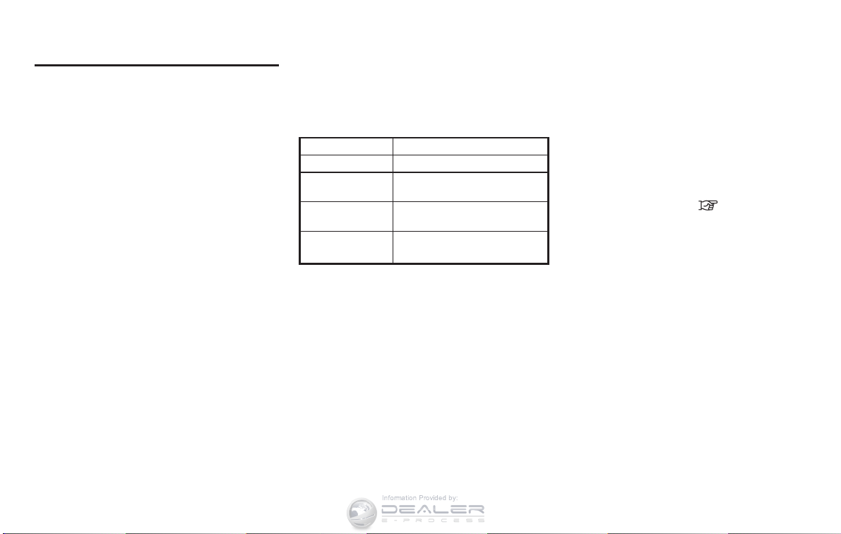
FLUIDS
. Before driving, check the fluid levels and
adjust as necessary using the specified fluid.
. Check the amount of fluid for the power
GTR-6 GT-R Overview
steering.
. Be sure to change the fluids listed below
with the specified fluids every 1,800 miles
(3,000 km).
ITEMS GT-R SPECIFIED FLUIDS
Engine oil Mobil 1, 0W-40*1
Transmission oil
Differential oil
(front and rear)
Brake fluid
*1: Mobil 1, 0W-40 (100% synthetic) is the factory fill
oil. The VR38 engine with its plasma-sprayed
bores was developed using this oil. NISSAN
cannot ensure proper engine operation and durability if other 0W-40 synthetic oil is used. If Mobil
1, 0W-40 is not available, Mobil 1, 10W-40 (100%
synthetic) may be used; however, some performance loss may be noticed.
*2: Genuine NISSAN Brake Fluid R35 Special DOT4
is the factory fill brake fluid. The Vehicle Dynamic
Control (VDC) unit and other related parts were
specially designed for this brake fluid and NISSAN
cannot ensure the best performance and proper
operation of the vehicle if other brake fluid is used.
Genuine NISSAN Transmission
Oil R35 Special
Castrol SAF-XJ 75W-140
Genuine NISSAN Brake Fluid
R35 Special DOT4*2
INSPECTION AND ADJUSTMENTS
OF TIRES, SUSPENSION AND
BRAKES
. Measure and adjust the wheel alignment.
. Check the tire pressure and the Tire
Pressure Monitoring System (TPMS) sensor.
. Make tire pressure adjustments only when
the tires are cool. (
“WHEELS AND
TIRES” page 8-29)
. Secure road wheel balance weights with
aluminum tape or equivalent.
. Check the heat deterioration and wear of the
brakes. (As necessary, the brake pad and
the brake disc rotor must be replaced as a
set of four with new ones.)
REPLENISHING COOLANT
Check the coolant level in the pressurized
coolant reservoir. Adjust the level so that the
fluid is between the MAX and MIN markings. For
the coolant, use genuine NISSAN Long Life
coolant. (On delivery of new vehicle, the
reservoir is filled to the MIN level. Be sure to
replenish approximately 0.3 to 0.4 US quart (0.3
to 0.4 liter) of coolant.)
COOLANT MIXTURE RATIO
Information Provided by:
For maximum cooling system performance, the
coolant mixture ratio should be the combination
of 30% antifreeze and 70% demineralized or
distilled water.
If ambient temperatures are anticipated below
58F(−158C), make sure a proper mixture ratio of
50% antifreeze and 50% demineralized or
distilled water mix is used.
COOL DOWN
Cool down the vehicle to help extend the life of
the vehicle if coolant temperatures are extremely
high. Drive the vehicle at 37 to 50 MPH (60 to
80 km/h), in 5th or 6th gear for 2 to 3 miles (3 to
5 km) and then stop the engine.
GT-R SPECIFIC VEHICLE
CHARACTERISTICS
REFUELING PRECAUTIONS
WARNING
Do not attempt to top off the fuel tank
after the fuel pump nozzle shuts off
automatically. Continued refueling may
cause fuel overflow, resulting in fuel
spray and possibly a fire. The fuel tank
is full at the first automatic shutoff.
To maximize vehicle performance, the fuel tank is
located as low as possible to lower the vehicle
center of gravity. The tank is also divided into
two parts. This fuel tank design causes higher
pressures inside the tank than other vehicles so
fuel spillage is possible by trying to top off the
fuel tank after automatic shutoff.
REFUELING STOPS BEFORE THE
TANK IS FULL
The fuel tank pressure is higher when the vehicle
is hot. If the vehicle is refueled when the vehicle
is hot, the fuel pump may automatically shut off
before the tank is full. This does not indicate that
there is a malfunction. This will not happen after
the vehicle has cooled.
GASOLINE SMELL
The fuel temperature is higher when the vehicle
is hot. This may cause a gasoline smell from the
vehicle. This does not indicate that there is a
malfunction. The smell will go away when the
fuel temperature has cooled.
OUTSIDE TEMPERATURE DISPLAY
INDICATES HIGHER TEMPERATURE
Heat from the engine compartment, radiator and
intercoolers can affect the outside temperature
display. The outside temperature display may
indicate a higher than actual temperature while
driving or stopped. This is normal.
IDLE SPEED IS NOT STEADY
The idle speed may not be steady when the
engine compartment is extremely hot. This is
normal. The engine speed will be steady when
the engine cools down.
In this case, the Malfunction Indicator Light (MIL)
may come on. After a few driving trips, the MIL
should turn off. If the light remains on after a few
driving trips, have the vehicle inspected by a
GT-R certified NISSAN dealer.
ENGINE SPEED IS RESTRICTED
To help protect the engine, the maximum engine
speed is automatically controlled in the following
conditions:
. Revving the engine with the shift lever in the
P
&
or &Nposition: The maximum engine
speed is 5,000 RPM
. Revving the engine when the engine coolant
GT-R Overview GTR-7

or oil is at a low or extremely high
Information Provided by:
temperature: The maximum engine speed
is 4,000 RPM
DISTORTION OF REAR WING
When the vehicle is parked in direct sunlight on
a hot day, the center of the rear wing may
become distorted. This is normal. When the
surface temperature of the rear wing is reduced,
the shape of the wing should return to normal.
UNEVEN WEAR OF TIRES
The NISSAN GT-R is equipped with high
performance, low profile, run-flat tires that are
optimized for performance and handling. The life
of these tires will be less than those of tires
installed on a typical vehicle, and you are likely to
experience uneven tire wear and tire noise
regardless of the type of tire used.
NOISES ARE HEARD WHILE DRIVING
. The GT-R brake pads use material that
provides a high amount of braking power
even in high temperatures. This material can
cause an intermittent screeching noise when
the brakes are applied. The noise decreases
as the brake pads wear.
. A screeching noise may be heard when the
brake pedal is depressed:
— When driving the vehicle for the first time
in the morning,
— After leaving the vehicle parked for
extended periods of time, or
— When the vehicle is damp following rain
showers or washing the vehicle.
These sounds are normal. The noise is
caused when the brake pads absorb moisture, and the noise stops after the brake is
applied several times.
. A screeching noise may also be heard when
the brake pedal is depressed:
— When repeatedly applying gentle brak-
ing, especially on a curve at a low
speed, or
— When the brake rotors have circular
scores with the brake temperature high.
. To maintain steady braking performance in
both extremely high and low temperatures,
the gap between the brake pad and caliper
is larger than normal and large-size brake
pads are used. When driving over a bump, a
light rattling sound may be heard from the
brake pad. This does not indicate that there
is a malfunction.
. When the brake disc r otor undergoes
thermal expansion, a rumbling noise may
be heard from the engaging portion of the
wheel and the brake disc rotor. This does
not indicate that there is a malfunction. The
noise will cease when the temperature
decreases.
. In addition to noise resulting from uneven
tire wear discussed in the previous section,
the GT-R tires are more rigid than a typical
passenger car tire and are made from a
specially formulated rubber to maximize the
vehicle’s performance capabilities. These
characteristics cause the GT-R tires to have
more road noise than a typical passenger
car tire. This road noise is normal.
. Due to the performance capabilities and
requirements of the GT-R, the sequential 6speed dual clutch transmission is unlike a
typical automatic transmission. You will likely
hear mechanical sounds from the transmission, particularly at slow speeds and at idle.
This condition is normal.
GTR-8 GT-R Overview
BRAKE DUST
Information Provided by:
This vehicle is equipped with high performance
brakes, and the characteristics of the brake pad
material may cause more brake dust than other
vehicles. NISSAN recommends a wheel coating
that helps prevent the brake dust from sticking
to the wheels. Contact a GT-R certified NISSAN
dealer for more details.
MECHANICAL LIMITED SLIP DIFFERENTIAL (LSD) CHARACTERISTICS
The differential oil has a high viscosity and is
very thick when cold. If the vehicle accelerates
from a stop with the steering wheel turned in
cold temperatures, the inner wheel tire may slip
and some noise or vibration may be heard. This
phenomenon is unique to vehicles equipped
with the Limited Slip Differential (LSD). When
the steering wheel is returned to the straightahead position or the differential oil warms up,
the noise and vibration decrease.
DUAL CLUTCH TRANSMISSION
The GT-R dual clutch transmission is a newlydeveloped system that uses an electronically
controlled multiple-disc wet clutch attached to
the highly efficient manual transmission. This
transmission has two driving modes.
A
&
position (Automatic gearshift):
.
allows automatic shifting of the manual
transmission.
M
.
&
position (Manual gearshift):
allows quick shifting of the manual transmission.
NOTE:
. &Mposition driving is recommended
when driving up hills or accelerating
from a stop on a cold morning.
M
.
&
position driving is recommended if
you feel shift shocks or jerkiness in the
A
&
position in cold temperatures.
. When starting or driving on a steep
uphill grade, shift to the
and operate the paddle shifter to shift
down to 1st gear similar to a manual
transmission vehicle.
The GT-R dual clutch transmission was developed specifically to maximize vehicle performance and driving enjoyment. The GT-R
transmission components were designed using
different engineering standards than typical
&
M
position
passenger car transmissions. Because of this,
the GT-R has different operating characteristics,
and various rattle noises may be heard during
some driving conditions because of the following items:
. Gear clearances
. Ultralight flywheel
. Dry sump lubrication
These noises do not indicate that there is a
malfunction.
GT-R Overview GTR-9
TRANSMISSION OPERATION CHARACTERISTICS
Information Provided by:
Mechanism Operation characteristics
. When the temperature of the transmission is high, the decreased friction from idling and driving at low speeds can cause rattling, shaking
Base Manual transmission
Multiple disc wet clutch
Electronic oil pressure
control
Changing modes
Gear clearances
and jarring noises. When the temperature of the transmission decreases, the noise will lessen.
. Clattering noises may be heard while shifting.
. When stopping the vehicle with the shift lever in the &
slowly move if the brake pedal is not depressed.
R
or &A↔&Mposition, be sure to firmly depress the brake pedal. The vehicle may
. Never depress the brake and accelerator pedals at the same time. Depressing the brake and accelerator pedals at the same time could
cause:
— The engine to stall
— The clutch to overheat
— Transmission damage
. To prevent stalling or transmission damage, start in first gear. The &
when reduced torque is necessary on snowy roads or extremely slippery surfaces.
. When the vehicle is stopped on a hill, do not hold the vehicle in place by depressing the accelerator pedal. Doing so may cause the clutch
to overheat and result in transmission damage. Use the brakes to prevent the vehicle from moving.
The following conditions are caused due to changes in fluid viscosity as a result of temperature changes.
. When the transmission fluid is extremely cold or extremely hot, the transmission may feel like it is slipping during shifts or there may be hard
shifts. This is normal. Transmission shifting should return to normal when the transmission fluid returns to normal operating temperatures.
. When the transmission fluid temperature is extremely cold, the time required to run a system check may increase. During the system check,
P
&
the shift lever must stay in the
noises during the transmission systems check.
. The higher shift speeds in the &
. Quick shifting in the R mode with the transmission in the &
may shift more slowly when the engine speed is low.
Appropriate gaps are provided between gears to achieve smooth gear rotation and steady tooth surface lubrication under the high-load driving
condition. However, this causes a rattling noise.
position. Move the shift lever after turning off the system check display. Also, it is normal to hear clicking
M
position may result in shift shock and jerkiness when starting or shifting.
M
position is available when the engine speed is high. However, the transmission
M
position second gear can be used to start moving the vehicle only
GTR-10 GT-R Overview
Mechanism Operation characteristics
Information Provided by:
. An ultralight flywheel is provided to achieve rapid engine response to the accelerator pedal operation and quick shifting response to the
paddle shifter operation. These are essential for a supercar. However, you may notice a large rattling noise from gears because engine
Ultralight flywheel
rotation fluctuations become larger while idling.
. Due to changes in engine speed through the operation of the air conditioner, rattling, shaking or jarring noises may be heard when idling or
driving at low speeds.
. Rattling noises may be heard when the engine is started or stopped.
High-efficiency dry sump lubrication is provided to achieve low agitation resistance of lubricant oil and allows smooth transmission gear rotation
Dry sump lubrication
that contribute to obtain a perfect balance between outstanding driving performance and improved environmental performance. However, you
may notice some rattling noise due to engine rotation fluctuations.
GT-R Overview GTR-11

MEMO
Information Provided by:
GTR-12 GT-R Overview
0 Illustrated table of contents
Information Provided by:
Seats, seat belts and Supplemental Restraint System
(SRS).............................................................. 0-2
Exterior ............................................................ 0-4
Front ........................................................... 0-2
Rear............................................................ 0-3
Front ........................................................... 0-4
Rear............................................................ 0-5
Passenger compartment ...................................... 0-6
Cockpit............................................................ 0-7
Instrument panel ................................................ 0-8
Meters and gauges............................................. 0-9
Engine compartment ......................................... 0-10
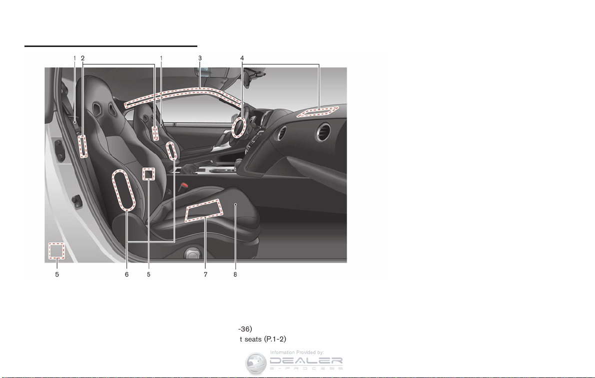
SEATS, SEAT BELTS AND
Information Provided by:
SUPPLEMENTAL RESTRAINT
SYSTEM (SRS)
FRONT
1. Seat belt (Page 1-5)
2. Rear seat walk-in lever (P.1-4)
3. Roof-mounted curtain side-impact supplemental
air bag system (if so equipped) (P.1-31)
4. Supplemental front-impact air bags (P.1-31)
0-2 Illustrated table of contents
5. Seat belt pretensioner (P.1-42)
6. Front seat-mounted side-impact supplemental air
bag system (if so equipped) (P.1-31)
7. Occupant classification sensor (pattern sensor)
(P.1-36)
8. Front seats (P.1-2)
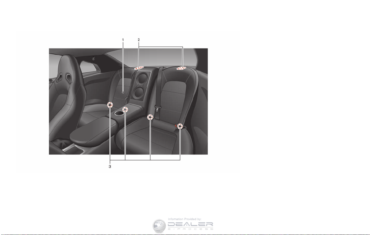
REAR
Information Provided by:
1. Rear seats
— Child restraint installation (P.1-13)
2. Child restraint anchor points (for top tether strap
child restraint) (P.1-16)
3. LATCH (Lower Anchors and Tethers for CHildren)
system (P.1-15)
Illustrated table of contents 0-3
EXTERIOR
Information Provided by:
ITEMS GT-R SPECIFIED PARTS
Road wheel
Tire*1
Brake pad*2
Brake disc rotor*2
*1: When tire replacement is required, replacing tires
as a set of four with new tires is recommended.
However, if a tire is punctured or damaged, it may
be possible to replace only the damaged tire.
Determining whether one tire or a complete set of
tires should be replaced is based on a number of
factors including tire wear and cond ition. Contact
your GT-R certified NISSAN dealer. They can
recommend if an individual tire or a complete set
should be replaced.
*2: The brake pad and the brake disc rotor must be
replaced as a set of four with new ones.
Genuine road wheel or an
equivalent specific to GT-R
Genuine tire or an equivalent
specific to GT-R
Genuine brake pad specific to
GT-R
Genuine brake disc rotor specific to GT-R
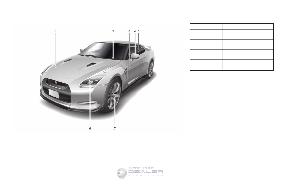
FRONT
1. Hood (P.3-17)
2. Windshield wiper and washer (P.2-45, P.8-19)
3. Doors (P.3-2, P.3-4, P.3-8)
4. Outside mirrors (P.3-27)
5. Power windows (P.2-56)
0-4 Illustrated table of contents
6. Headlight and turn signal (P.2-47, P.8-26)
7. Tires and wheels (P.5-3, P.6-2, P.8-29, P.9-7)
ITEMS GT-R SPECIFIED FUEL
Information Provided by:
Unleaded premium gasoline with an
Fuel
*1: Use unleaded premium gasoline with an octane
rating of at least 93 AKI (Anti- Knock Index) number
(Research octane number 98) to maximize vehicle
performance. If 93 AKI number (Research octane
number 98) premium gasoline is not available, you
may use unleaded premium gasoline with an
octane rating of at least 91 AKI number (Research
octane number 96), but you may notice a decrease
in performance.
octane rating of at least 93 AKI (AntiKnock Index) number (Research octane
number 98)*1
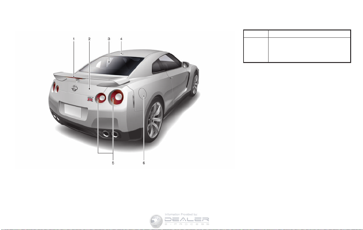
REAR
1. High-mounted stop light (P.8-26)
2. Trunk (P.3-8, P.3-19)
3. Rear window defroster (P.2-46)
4. Satellite antenna*
5. Rear combination light (P.8-26)
6. Fuel-filler door (P.3-22, P.9-3)
*: Refer to the separate Multi Function Display
Owner’s Manual.
Illustrated table of contents 0-5
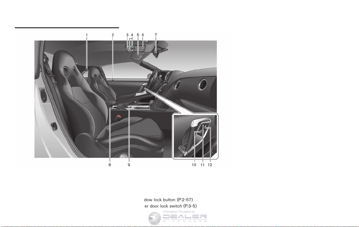
PASSENGER COMPARTMENT
Information Provided by:
1. Coat hooks (P.2-56)
2. Inside lock knob (P.3-5)
3. Interior light control switch (P.2-58)
4. Map lights (P.2-58)
5. Sun visors (P.3-26)
6. Sunglasses holder (P.2-54)
0-6 Illustrated table of contents
7. Inside rearview mirror (P.2-60, P.3-26)
8. Center console box (P.2-56)
9. Cup holders (P.2-53)
10. Power window switches (P.2-56)
11. Window lock button (P.2-57)
12. Power door lock switch (P.3-5)
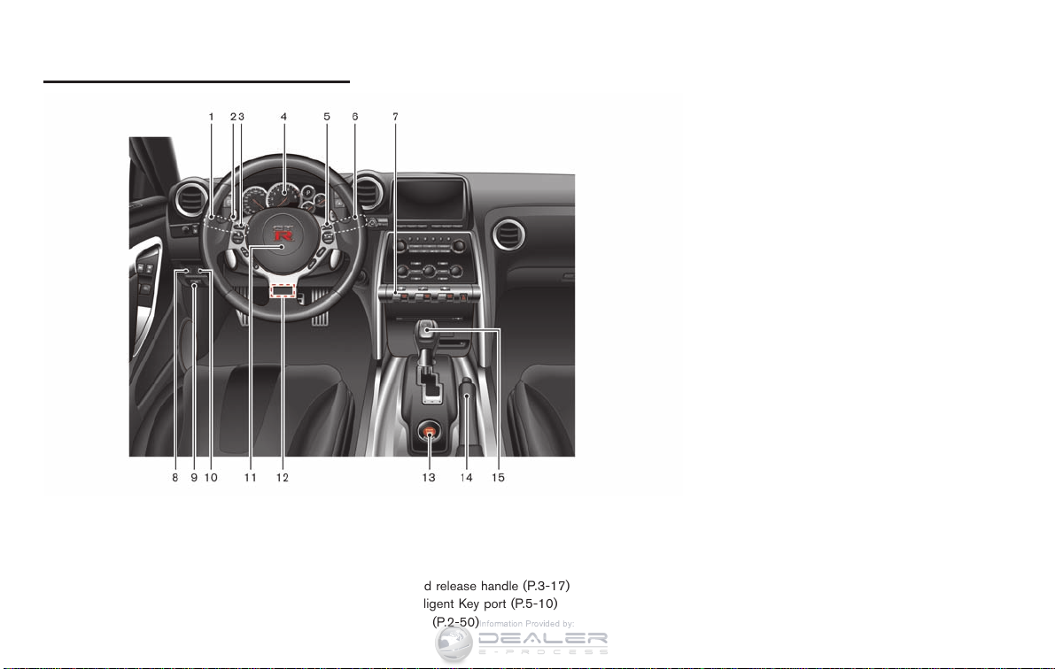
COCKPIT
Information Provided by:
12. Tilting/telescopic steering wheel lever (P.3-25)
13. Push-button ignition switch (P.5-8)
14. Parking brake (P.5-27, P.5-37)
15. Shift lever (P.5-13)
*: Refer to the separate Multi Function Display
Owner’s Manual.
1. Headlight and turn signal switch (P.2-47)
2. Paddle shifters (P.5-13)
3. Steering-wheel-mounted controls (left side)*
4. Meters and gauges (P.2-4)
5. Steering-wheel-mounted controls (right side)
— MRK (Mark) switch*
— Cruise control (P.5-28)
6. Windshield wiper and washer switch (P.2-45)
7. VDC, transmission and suspension set up
switches (P.5-21)
8. Trunk lid release switch (P.3-19)
9. Hood release handle (P.3-17)
10. Intelligent Key port (P.5-10)
11. Horn (P.2-50)
Illustrated table of contents 0-7
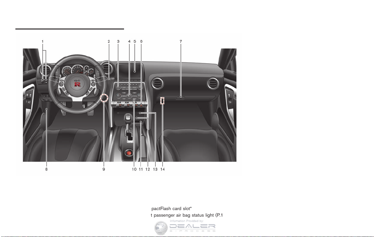
INSTRUMENT PANEL
Information Provided by:
13. Compact Disc slot*
14. Trunk release power cancel switch (P.3-20)
*: Refer to the separate Multi Function Display
Owner’s Manual.
1. Outside mirror control switch (P.3-27)
2. Center dial*
3. Audio system*
4. Heater and air conditioner*
5. Multi function display*
6. Hazard warning flasher switch (P.2-50)
0-8 Illustrated table of contents
7. Glove box (P.2-55)
8. Fuse box cover (P.8-22)
9. Power outlet (P.2-52)
10. Rear window defroster switch (P.2-46)
11. CompactFlash card slot*
12. Front passenger air bag status light (P.1-37)
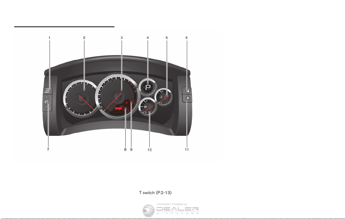
METERS AND GAUGES
Information Provided by:
NOTE:
. Meters and gauges will illuminate
when the ignition switch is pushed to
the ON position.
. The needle indicators may move
slightly after the ignition switch is
pushed to the OFF position. This does
not indicate that there is a malfunction.
1. Trip A/B reset switch (P.2-5)
2. Speedometer (P.2-5)
3. Tachometer (P.2-6)/Upshift indicator (P.2-8)
4. Transmission position indicator (P.2-7)
5. Engine coolant temperature gauge (P.2-6)
6. ENTER switch (P.2-13)
7. Instrument brightness control switch (P.2-10)
8. Vehicle information display (P.2-10)
9. Odometer/twin trip odometer (P.2-5)
10. Fuel gauge (P.2-7)
11. NEXT switch (P.2-13)
Illustrated table of contents 0-9
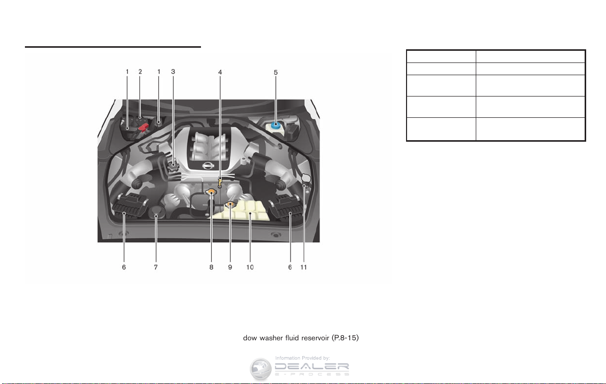
ENGINE COMPARTMENT
Information Provided by:
ITEMS GT-R SPECIFIED FLUIDS
Engine oil Mobil 1, 0W-40*1
Transmission oil
Differential oil
(front and rear)
Brake fluid
*1: Mobil 1, 0W-40 (100% synthetic) is the factory fill
oil. The VR38 engine with its plasma-sprayed
bores was developed using this oil. NISSAN
cannot ensure proper engine operation and durability if other 0W-40 synthetic oil is used. If Mobil
1, 0W-40 is not available, Mobil 1, 10W-40 (100%
synthetic) may be used; however, some performance loss may be noticed.
*2: Genuine NISSAN Brake Fluid R35 Special DOT4
is the factory fill brake fluid. The Vehicle Dynamic
Control (VDC) unit and other related parts were
specially designed for this brake fluid and NISSAN
cannot ensure the best performance and proper
operation of the vehicle if other brake fluid is used.
Genuine NISSAN Transmission
Oil R35 Special
Castrol SAF-XJ 75W-140
Genuine NISSAN Brake Fluid
R35 Special DOT4*2
1. Fuse/fusible link holder (P.8-22)
2. Battery (P.8-15)
3. Engine oil filler cap (P.8-12)
4. Engine oil dipstick (P.8-12)
5. Brake fluid reservoir (P.8-14)
6. Air cleaner (P.8-19)
0-10 Illustrated table of contents
7. Power steering fluid reservoir (P.8-13)
8. Radiator filler cap (P.8-9)
9. Coolant reservoir cap (pressure type) (P.8-9)
10. Coolant reservoir (P.8-9)
11. Window washer fluid reservoir (P.8-15)

MEMO
Information Provided by:
Illustrated table of contents 0-11

MEMO
Information Provided by:
0-12 Illustrated table of contents

1 Safety — Seats, seat belts and supple-
Information Provided by:
mental restraint system
Seats .............................................................. 1-2
Seat belts ........................................................ 1-5
Child restraints ................................................ 1-13
Front seats ................................................... 1-2
Precautions on seat belt usage ......................... 1-5
Child safety .................................................. 1-7
Pregnant women............................................ 1-9
Injured persons.............................................. 1-9
Three-point type seat belt with retractor .............. 1-9
Seat belt extenders....................................... 1-12
Seat belt maintenance ................................... 1-12
Precautions on child restraints......................... 1-13
Lower Anchors and Tethers for CHildren system
(LATCH) .................................................... 1-15
Top tether strap child restraint......................... 1-16
Child restraint installation using LATCH ............. 1-17
Child restraint installation using the seat belts..... 1-21
Booster seats.................................................. 1-27
Precautions on booster seats.......................... 1-27
Booster seat installation................................. 1-29
Supplemental restraint system ............................. 1-31
Precautions on supplemental restraint system ..... 1-31
NISSAN Advanced Air Bag System
(front seats) ................................................ 1-36
Front seat-mounted side-impact supplemental air
bag and roof-mounted curtain side-impact
supplemental air bag system (if so equipped) . .... 1-40
Seat belts with pretensioners (front seats) ......... 1-42
Supplemental air bag warning labels................. 1-43
Supplemental air bag warning light................... 1-43
Repair and replacement procedure................... 1-44

SEATS
Information Provided by:
WARNING
. Do not ride in a moving vehicle
when the seatback is reclined. This
can be dangerous. The shoulder belt
will not be against your body. In an
accident, you could be thrown into it
and receive neck or other serious
injuries. You could also slide under
the lap belt and receive serious
internal injuries.
. For the most effective protection
when the vehicle is in motion, the
seat should be upright. Always sit
well back in the seat with both feet
on the floor and adjust the seat
properly. (
SEAT BELT USAGE” page 1-5)
. After adjustment, gently rock in the
seat to make sure it is securely
locked.
. Do not leave children unattended
inside the vehicle. They could unknowingly activate switches or controls. Unattended children could
become involved in serious accidents.
1-2 Safety — Seats, seat belts and supplemental restraint system
“PRECAUTIONS ON
FRONT SEATS
Front power seat adjustment
Operating tips
. The power seat motor has an auto-reset
overload protection circuit. If the motor
stops during operation, wait 30 seconds,
then reactivate the switch.
. Do not operate the power seat switch for a
long period of time when the engine is off.
This will discharge the battery.
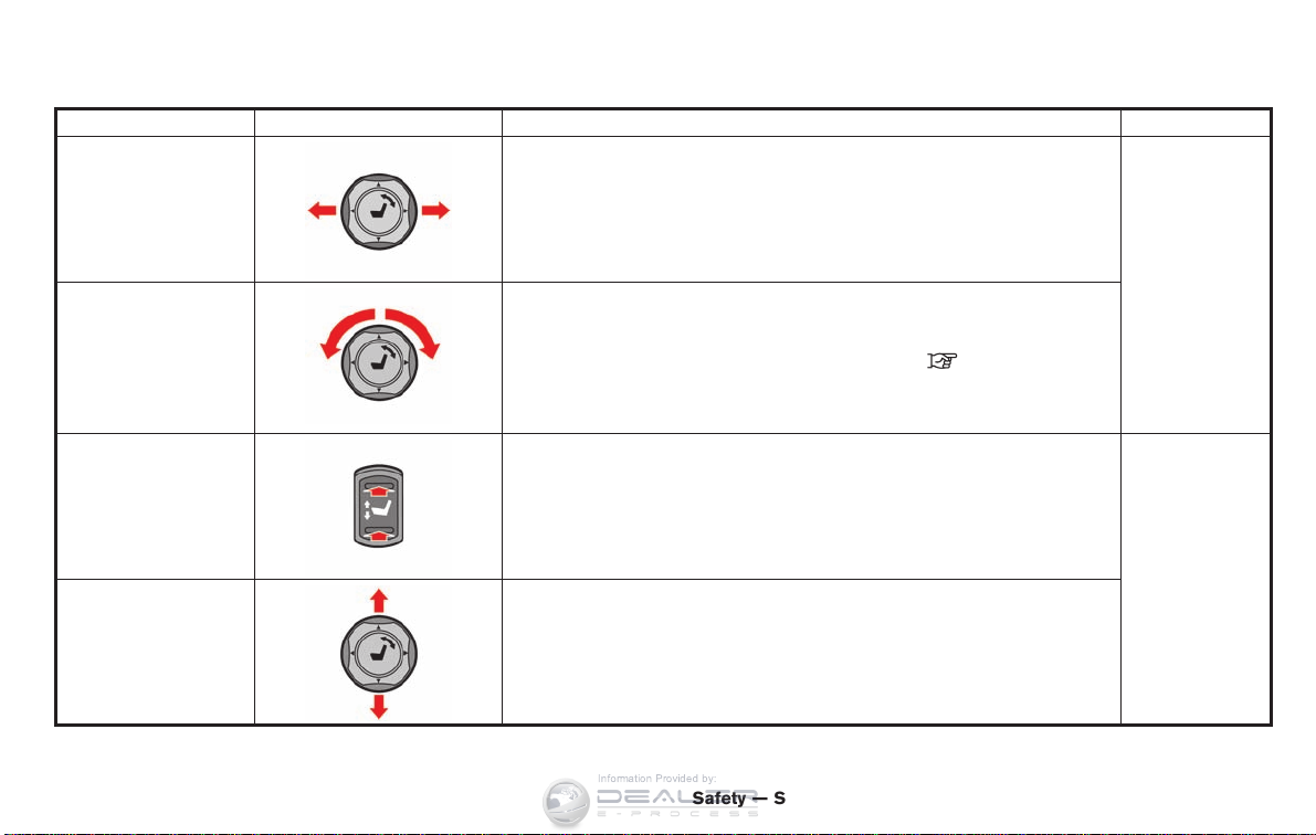
Seat Adjustment Switch Operation Location
Information Provided by:
Forward and backward
Move the switch
A
forward or backward until the desired seat position is obtained.
*
Reclining
Seat lifter (front)
Seat lifter (rear)
Turn the switch
obtained.
The reclining feature allows adjustment of the seatback for occupants of different sizes
for added comfort and to help obtain proper seat belt fit. (
SEAT BELT USAGE” page 1-5)
Also, the seatback can be reclined to allow occupants to rest when the vehicle is
stopped and the transmission is in the
Push the switch up or down
Move the switch
A
forward and backward until the desired seatback angle is
*
“PRECAUTIONS ON
P
&
position with the parking brake fully applied.
B
to raise or lower the front portion of the seat.
*
A
up or down to raise or lower the rear portion of the seat.
*
Safety — Seats, seat belts and supplemental restraint system 1-3
Driver’s and front
passenger’s seats
Driver’s seats

Passenger’s seat slide:
Information Provided by:
Pushing the passenger’s seat slide switch will
slide the passenger’s seat forward or backward
to the desired position.
Rear seat walk-in
This feature makes it easier to get in and out of
the rear seat. Use the following procedure when
getting in and out of the rear seat.
1. Lift up the lever and tilt the seatback
forward.
2. Use the seat adjustment switch
passenger’s seat slide switch
the seat forward to a position where it will be
easier to enter or exit the rear seats. Fold the
shoulder belt guide for easier access to the
rear seat.
3. To return the seat to its original position, lift
up the seatback and use the seat adjust-
1-4 Safety — Seats, seat belts and supplemental restraint system
*
*
C
A
ment switch to return the seat to its original
position.
CAUTION
. When returning the seat to its
original position, confirm that the
seat and seatback are locked properly.
. Be careful not to pinch your hand or
foot or bump your head when operating the walk-in seat.
NOTICE
Do not place any objects near the
seatback of the front seats. They may
be pinched and damaged.
or the
to slide

SEAT BELTS
Information Provided by:
PRECAUTIONS ON SEAT BELT
USAGE
If you are wearing yo ur seat belt properly
adjusted, and you are sitting upright and well
back in your seat with both feet on the floor, your
chances of being injured or killed in an accident
and/or the severity of injury may be greatly
reduced. NISSAN strongly encourages you and
all of your passengers to buckle up every time
you drive, even if your seating position includes a
supplemental air bag.
Most U.S. states and Canadian provinces
or territories specify that seat belts be
worn at all times when a vehicle is being
driven.
Safety — Seats, seat belts and supplemental restraint system 1-5

WARNING
Information Provided by:
. Every person who drives or rides in
this vehicle should use a seat belt at
all times. Children should be properly restrained in the rear seat and,
if appropriate, in a child restraint.
. The seat belt should be properly
adjusted to a snug fit. Failure to do
so may reduce the effectiveness of
the entire restraint system and increase the chance or severity of
injury in an accident. Serious injury
or death can occur if the seat belt is
not worn properly.
. Always route the shoulder belt over
your shoulder and across your
chest. Never put the belt behind
your back, under your arm or across
your neck. The belt should be away
from your face and neck, but not
falling off your shoulder.
. Position the lap belt as low and
snug as possible AROUND THE
HIPS, NOT THE WAIST. A lap belt
worn too high could increase the
risk of internal injuries in an accident.
. Be sure the seat belt tongue is
securely fastened to the proper
buckle.
. Do not wear the seat belt inside out
or twisted. Doing so may reduce its
effectiveness.
. Do not allow more than one person
to use the same seat belt.
. Never carry more people in the
vehicle than there are seat belts.
. If the seat belt warning light glows
continuously while the ignition is
turned ON with all doors closed and
all seat belts fastened, it may indicate a malfunction in the system.
Have the system checked by a GT-R
certified NISSAN dealer.
. No changes should be made to the
seat belt system. For example, do
not modify the seat belt, add material, or install devices that may
change the seat belt routing or
tension. Doing so may affect the
operation of the seat belt system.
Modifying or tampering with the
seat belt system may r esult in
serious personal injury.
. Once a seat belt pretensioner has
1-6 Safety — Seats, seat belts and supplemental restraint system
activated, it cannot be reused and
must be replaced together with the
retractor. See a GT-R certified
NISSAN dealer.
. Removal and installation of the
pretensioner system components
should be done by a GT-R certified
NISSAN dealer.
. All seat belt assemblies, including
retractors and attaching hardware,
should be inspected after any collision by a GT-R certified NISSAN
dealer. NISSAN recommends that
all seat belt assemblies in use
during a collision be replaced unless the collision was minor and the
belts show no damage and continue
to operate properly.
Seat belt assemblies not in use
during a collision should also be
inspected and replaced if either
damage or improper operation is
noted.
. All child restraints and attaching
hardware should be inspected after
any collision. Always follow the
restraint manufacturer’s inspection
instructions and replacement re-

commendations. The child restraints
Information Provided by:
should be replaced if they are
damaged.
CHILD SAFETY
Children need adults to help protect them.
They need to be properly restrained.
In addition to the general information in this
manual, child safety information is available from
many other sources, including doctors, teachers,
government traffic safety offices, and community
organizations. Every child is different, so be sure
to learn the best way to transport your child.
There are three basic types of child restraint
systems:
. Rear facing child restraint
. Front facing child restraint
. Booster seat
The proper restraint depends on the child’s size.
Generally, infants (up to about 1 year and less
than 20 lb (9 kg)) should be placed in rear
facing child restraints. Front facing child restraints are available for children who outgrow
rear facing child restraints and are at least 1 year
old. Booster seats are used to help position a
vehicle lap/shoulder belt on a child who can no
longer use a front facing child restraint.
WARNING
Infants and children need special protection. The vehicle’s seat belts may not
Safety — Seats, seat belts and supplemental restraint system 1-7

fit them properly. The shoulder belt may
Information Provided by:
come too close to the face or neck. The
lap belt may not fit over their small hip
bones. In an accident, an improperly
fitting seat belt could cause serious or
fatal inju ry. Always use appropriate
child restraints.
All U.S. states and Canadian provinces or
territories require the use of approved child
restraints for infants and small children.
(
“CHILD RESTRAINTS” page 1-13)
Also, there are other types of child restraints
available for larger children for additional protection.
NISSAN recommends that all pre-teens
and children be restrained in the rear seat.
According to accident statistics, children
are safer when properly restrained in the
rear seat than in the front seat.
This is especially important because your
vehicle has a supplemental restraint system (air bag system) for the front passenger. (
SYSTEM” page 1-31)
“SUPPLEMENTAL RESTRAINT
Infants
Infants up to at least one year old should be
placed in a rear facing child restraint. NISSAN
recommends that infants be placed in child
restraints that comply with Federal Motor
Vehicle Safety Standards or Canadian Motor
Vehicle Safety Standards. You should choose a
child restraint which fits your vehicle and always
follow the manufacturer’s instructions for installation and use.
Small children
Children that are over one year old and weigh at
least 20 lb (9 kg) can be placed in a forward
facing child restraint. Refer to the manufacturer’s
instructions for minimum and maximum weight
and height recommendations. NISSAN recommends that small children be placed in child
restraints that comply with Federal Motor
Vehicle Safety Standards or Canadian Motor
Vehicle Safety Standards. You should choose a
child restraint that fits your vehicle and always
follow the manufacturer’s instructions for installation and use.
Larger children
Children who are too large for child restraints
should be seated and restrained by the seat
belts which are provided. The seat belt may not
fit properly if the child is less than 4 ft 9 in (142.5
cm) tall and weighs between 40 lb (18 kg) and
80 lb (36 kg). A booster seat should be used to
1-8 Safety — Seats, seat belts and supplemental restraint system
obtain proper seat belt fit.
NISSAN recommends that a child be placed in a
commercially availableboosterseatifthe
shoulder belt in the child’s seating position fits
close to the face or neck or if the lap portion of
the seat belt goes across the abdomen. The
booster seat should raise the child so that the
shoulder belt is properly positioned across the
top, middle portion of the shoulder and the lap
belt is low on the hips. A booster seat can only
be used in seating positions that have a threepoint type seat belt. The booster seat should fit
the vehicle seat and have a label certifying that it
complies with Federal Motor Vehicle Safety
Standards or Canadian Motor Vehicle Safety
Standards. Once the child has grown so the
shoulder belt is no longer on or near the face
and neck, use the shoulder belt without the
booster seat.
WARNING
Never let a child stand or kneel on any
seat and do not allow a child in the
cargo areas while the vehicle is moving.
The child could be seriously injured or
killed in an accident or sudden stop.

PREGNANT WOMEN
Information Provided by:
NISSAN recommends that pregnant women use
seat belts. The seat belt should be worn snug,
and always position the lap belt as low as
possible around the hips, not the waist, and
place the shoulder belt over your shoulder and
across your chest. Never run the lap/shoulder
belt over your abdominal area. Contact your
doctor for specific recommendations.
INJURED PERSONS
NISSAN recommends that injured persons use
seat belts, depending on the injury. Check with
your doctor for specific recommendations.
THREE-POINT TYPE SEAT BELT
WITH RETRACTOR
WARNING
. Every person who drives or rides in
this vehicle should use a seat belt at
all times.
. Do not ride in a moving vehicle
when the seatback is reclined. This
can be dangerous. The shoulder belt
will not be against your body. In an
accident, you could be thrown into it
and receive neck or other serious
injuries. You could also slide under
the lap belt and receive serious
internal injuries.
. For the most effective protection
when the vehicle is in motion, the
seat should be upright. Always sit
well back in the seat with both feet
on the floor and adjust the seat belt
properly.
Fastening the seat belts
1. Adjust the seat. ( “SEATS” page 1-2)
2. Slowly pull the seat belt out of the retractor
and insert the tongue into the buckle until
you hear and feel the latch engage.
. The retractor is designed to lock
during a sudden stop or on impact.
A slow pulling motion permits the
belt to move, and allows you some
freedom of movement in the seat.
. If the seat belt cannot be pulled
from its fully retracted position,
firmly pull the belt and release it.
Then smoothly pull the belt out of
Safety — Seats, seat belts and supplemental restraint system 1-9

the retractor.
Information Provided by:
3. Position the lap belt portion low and snug
on the hips as shown.
4. Pull the shoulder belt portion toward the
retractor to take up extra slack. Be sure the
shoulder belt is routed over your shoulder
and across your chest.
The three-point type seat belts for the front
passenger and rear seats have two modes of
operation:
. Emergency Locking Retractor (ELR)
. Automatic Locking Retractor (ALR)
The Emergency Locking Retractor (ELR) mode
allows the seat belt to extend and retract to
1-10 Safety — Seats, seat belts and supplemental restraint system
allow the driver and passengers some freedom
of movement in the seat. The ELR locks the seat
belt when the vehicle slows down rapidly or
during impacts.
The Automatic Locking Retractor (ALR) mode or
child restraint mode locks the seat belt for child
restraint installation.
When the ALR mode is activated the seat belt
cannot be extended again until the seat belt
tongue is detached from the buckle and fully
retracted. The seat belt returns to the ELR mode
after the seat belt is fully retracted.
“CHILD RESTRAINTS” page 1-13)
(
The ALR mode should be used only for
child restraint installation. During normal
seat belt use by an occupant, the ALR
mode should not be activated. If it is
activated it may cause uncomfortable seat
belt tension. It can also change the operation of the front passenger air bag.
“Front passenger air bag and status
(
light” page 1-37)
WARNING
When fastening the seat belts, be
certain that seatbacks are completely
secured in the latched position. If they
are not completely secured, passengers
may be injured in an accident or sudden

stop.
Information Provided by:
To increase your confidence in the seat belts,
check the operation as follows:
. Grasp the shoulder belt and pull forward
quickly. The retractor should lock and
restrict further belt movement.
If the retractor does not lock during this check or
if you have any question about seat belt
operation, see a GT-R certified NISSAN dealer.
Unfastening the seat belts
To unfasten the seat belt, push the button on the
buckle. The seat belt automatically retracts.
Checking seat belt operation
Seat belt retractors are designed to lock seat
belt movement by two separate methods:
. When the belt is pulled quickly from the
retractor.
. When the vehicle slows down rapidly.
Safety — Seats, seat belts and supplemental restraint system 1-11

certified NISSAN dealer for assistance if the
Information Provided by:
extender is required.
. Only NISSAN seat belt extenders,
made by the same company which
made the original equipment seat
belts, should be used with the
NISSAN seat belts.
. Adults and children who can use the
standard seat belt should not use an
extender. Such unnecessary use
could r esult in serious personal
Shoulder belt arm (for front seats)
Before fastening the seat belt, pull the shoulder
belt arm forward until it clicks at the lock
position. The arm can also be folded down to
allow rear seat passengers easier access.
Pulling the arm forward will allow an easy access
to the belt.
SEAT BELT EXTENDERS
If, because of body size or driving position, it is
not possible to properly fit the lap-shoulder belt
and fasten it, an extender is available that is
compatible with the installed seat belts. The
extender adds approximately 8 in (200 mm) of
length and may be used for either the driver or
front passenger seating position. See a GT-R
injury in the event of an accident.
. Never use seat belt extenders to
install child restraints. If the child
restraint is not secured properly, the
child could be seriously injured in a
collision or a sudden stop.
SEAT BELT MAINTENANCE
. To clean the seat belt webbings, apply a
mild soap solution or any solution recommended for cleaning upholstery or carpets.
Then, wipe with a cloth and allow the seat
belts to dry in the shade. Do not allow the
seat belts to retract until they are completely
dry.
. If dirt builds up in the shoulder belt
1-12 Safety — Seats, seat belts and supplemental restraint system
WARNING
guide of the seat belt anchors, the seat
belts may retract slowly. Wipe the shoulder
belt guide with a clean, dry cloth.
. Periodically check to see that the seat
belt and the metal components such as
buckles, tongues, retractors, flexible wires
and anchors work properly. If loose parts,
deterioration, cuts or other damage on the
webbing is found, the entire seat belt
assembly should be replaced.

CHILD RESTRAINTS
Information Provided by:
PRECAUTIONS ON CHILD
RESTRAINTS
WARNING
. Infants and small children should
always be placed in an appropriate
child restraint while riding in the
vehicle. Failure to use a child restraint can result in serious injury or
death.
. Infants and small children should
never be carried on your lap. It is not
possible for even the strongest
adult to resist the forces of a severe
accident. The child could be crushed
between the adult and parts of the
vehicle. Also, do not put the same
seat belt around both your child and
yourself.
. Even with the NISSAN Advanced Air
Bag System, never install a rearfacing child restraint in the front
seat. An inflating front air bag could
seriously injure or kill your child. A
rear-facing child restraint must only
be used in the rear seat.
. NISSAN recommends that the child
restraint be installed in the rear
Safety — Seats, seat belts and supplemental restraint system 1-13
seat. According to accident statistics, children are safer when properly restrained in the rear seat than
in the front seat. If you must install a
front facing child restraint in the
front seat. (
INSTALLATION USING THE SEAT
BELTS” page 1-21)
. Improper use or improper installa-
tion of a child restraint can increase
the risk or severity of injury for both
the child and other occupants of the
vehicle and can lead to serious
injury or death in an accident.
. Follow all of the child restraint
manufacturer’s instructions for installation and use. When purchasing
a child restraint, be sure to select
one which will fit your child and
vehicle. It may not be possible to
properly install some types of child
restraints in your vehicle.
. If the child restraint is not anchored
properly, the risk of a child being
injured in a collision or a sudden
stop greatly increases.
. Child restraint anchor points are
designed to withstand only those
“CHILD RESTRAINT

loads imp osed by correctly fitte d
Information Provided by:
child restraints. Under no circumstances are they to be used for adult
seat belts or harnesses.
. Adjustable seatbacks should be
positioned to fit the child restraint,
but as upright as possible.
. After attaching the child restraint,
test it before you place the child in
it. Push it from side to side while
holding the seat near the LATCH
attachment or by the seat belt path.
The child restraint should not move
more than 1 inch (25 mm) from side
to side. Try to tug it forward and
check to see if the belt holds the
restraint in place. If the restraint is
not secure, tighten the belt as
necessary, or put the restraint in
another seat and test it again. You
may need to try a different child
restraint. Not all child restraints fit
in all types of vehicles.
. When your child restraint is not in
use, keep it secured with the LATCH
System or a seat belt to prevent it
from being thrown around in case of
a sudden stop or accident.
Remember that a child restraint left in a
closed vehicle can become very hot.
Check the seating surface and buckles
before placing your child in the child
restraint.
This vehicle is equipped with a universal child
restraint lower anchor system, referred to as the
Lower Anchors and Tethers for CHildren System
or LATCH. Some child restraints include two
rigid or webbing-mounted attachments that can
be connected to these lower anchors.
(
“CHILD RESTRAINT INSTALLATION
USING LATCH” page 1-17)
If you do not have a LATCH compatible child
restraint, the vehicle seat belts can be used. In
general, child restraints are also designed to be
installed with the lap portion of a lap/shoulder
seat belt. (
“CHILD RESTRAINT INSTAL-
LATION USING THE SEAT BELTS” page 1-21)
Several manufacturers offer child restraints for
infants and small children of various sizes. When
selecting any child restraint, keep the following
points in mind:
. Choose only a restraint with a label certifying
that it complies with Federal Motor Vehicle
Safety Standard 213 or Canadian Motor
Vehicle Safety Standard 213.
1-14 Safety — Seats, seat belts and supplemental restraint system
CAUTION
. Check the child restraint in your vehicle to
be sure it is compatible with the vehicle’s
seat and seat belt system.
. If the child restraint is compatible with your
vehicle, place your child in the child restraint
and check the various adjustments to be
sure the child restraint is compatible with
your child. Choose a child restraint that is
designed for your child’s height and weight.
Always follow all recommended procedures.
All U.S. states and Canadian provinces or
territories require that infants and small
children be restrained in an approved child
restraint at all times while the vehicle is
being operated. Canadian law requires the
top te ther strap on front-facing child
restraints be secured to the designated
anchor point on the vehicle.

for four occupants, two in the front
Information Provided by:
seats and two in the rear seats.
Never use the rear console as a
seating position or for a child restraint.
. Child restraint anchor points are
designed to withstand only those
loads imp osed by correctly fitte d
child restraints. Under no circumstance are they to be used for adult
seat belts or harnesses.
LATCH label location
Lower Anchors and Tethers for
CHildren SYSTEM (LATCH)
Your vehicle is equipped with special anchor
points that are used with Lower Anchors and
Tethers for CHildren System (LATCH) compatible child restraints. This system may also be
referred to as the ISOFIX or ISOFIX compatible
system. With this system, you do not have to use
a vehicle seat belt to secure the child restraint.
The LATCH anchor points are provided to install
child restraints in the rear outboard seating
positions only. Do not attempt to install a child
restraint in the center position using the LATCH
anchors.
LATCH lower anchor point locations
LATCH lower anchor location
The LATCH anchors are located at the rear of
the seat cushion near the seatback. A label is
attached to the seatback to help you locate the
LATCH anchors.
WARNING
. Attach LATCH compatible child re-
straints only at the locations shown
in the illustration. If a child restraint
is not secured properly, your child
could be seriously injured or killed
in an accident.
. The GT-R has seats and seat belts
Safety — Seats, seat belts and supplemental restraint system 1-15

LATCH webbing-mounted attachment
Information Provided by:
Installing child restraint LATCH anchor attachments
LATCH compatible child restraints include two
rigid or webbing-mounted attachments that can
be connected to two anchors located at certain
seating positions in your vehicle. With this
system, you do not have to use a vehicle seat
belt to secure the child restraint. Check your
child restraint for a label stating that it is
compatible with LATCH. This information may
also be in the instructions provided by the child
restraint manufacturer.
LATCH child restraints generally require the use
of a top tether strap. (
STRAP CHILD RESTRAINT” page 1-16)
When installing a child restraint, carefully read
and follow the instructions in this manual and
those supplied with the child restraint.
(
USING LATCH” page 1-17)
LATCH rigid attachment
“CHILD RESTRAINT INSTALLATION
1-16 Safety — Seats, seat belts and supplemental restraint system
“TOP TETHER
TOP TETHER STRAP CHILD RESTRAINT
If the manufacturer of your child restraint
requires the use of a top tether strap, it must
be secured to an anchor point.
WARNING
Child restraint anchor points are designed to withstand only those loads
imposed by correctly fitted child restraints. Under no circumstances are
they to be used for adult seat belts or
harnesses.

Top tether anchor point locations
Information Provided by:
Anchor points are located on the rear parcel
shelf.
Installing top tether strap
First, secure the child restraint with the LATCH
system (rear bench outboard seating positions
only) or the seat belt, as applicable.
Flip up the anchor cover from the anchor point
which is located directly behind the child seat.
Position the top tether strap over the top of the
seatback and secure it to the tether anchor
bracket that provides the straightest installation.
Tighten the strap according to the manufacturer’s instructions to remove any slack.
If you have any questions when installing a
top tether strap child restraint on the rear
seat, consult your GT-R certified NISSAN
dealer for details.
CHILD RESTRAINT INSTALLATION
USING LATCH
WARNING
. Attach LATCH compatible child re-
straints only at the locations shown.
If a child restraint is not secured
properly, your child could be seriously injured or killed in an accident. (
Tethers for CHildren SYSTEM
(LATCH)” page 1-15)
. The LATCH anchors are designed to
withstand only those loads imposed
by correctly fitted child restraints.
Under no circumstance are they to
be used for a dult seat belts or
harnesses.
. Inspect the lower anchors by insert-
ing your fingers into the lower
anchor area and feeling to make
sure there are no obstructions over
the LATCH anchors, such as seat
belt webbing or seat cushion material. The child restraint will not be
secured properly if the LATCH anchors are obstructed.
“Lower Anchors and
Front-facing
Front facing — step 2
Follow these steps to install a front-facing child
restraint using LATCH:
1. Position the child restraint on the seat.
Always follow the child restraint manufacturer’s instructions.
Safety — Seats, seat belts and supplemental restraint system 1-17

2. Secure the child restraint anchor attach-
Information Provided by:
Front facing — step 2
ments to the LATCH lower anchors. Check
to make sure the LATCH attachment is
properly attached to the lower anchors.
3. The back of the child restraint should be
secured against the vehicle seatback. If the
seating position does not have an adjustable
head restraint and it is interfering with the
proper child restraint fit, try another seating
position or a different child restraint.
4. For child restraints that are equipped with
webbing mounted attachments, remove any
additional slack from the anchor attachments. Press downward and rearward firmly
in the center of the child restraint with your
knee to compress the vehicle seat cushion
and seatback while tightening the webbing
of the anchor attachments.
5. If the child restraint is equipped with a top
tether strap, route the top tether strap and
Front facing — step 4
secure the tether strap to the tether anchor
point. (
“TOP TETHER STRAP CHILD
RESTRAINT” page 1-16)
1-18 Safety — Seats, seat belts and supplemental restraint system
6. After attaching the child restraint, test it
Front facing — step 6
before you place the child in it. Push it from
side to side while holding the seat near the
LATCH attachment or by the seat belt path.
The child restraint should not move more
than 1 inch (25 mm) from side to side. Try to
tug it forward and check to see if the belt
holds the restraint in place. If the restraint is
not secure, tighten the belt as necessary, or
put the restraint in another seat and test it
again. You may need to try a different child
restraint. Not all child restraints fit in all types
of vehicles.
7. Check to make sure the child restraint is
properly secured prior to each use. If the
child restraint is loose, repeat steps 3

through 6.
Information Provided by:
Rear-facing
Rear facing — step 2
Follow these steps to install a rear-facing child
restraint using LATCH:
1. Position the child restraint on the seat.
Always follow the child restraint manufacturer’s instructions.
Safety — Seats, seat belts and supplemental restraint system 1-19
2. Secure the child restraint anchor attach-
Rear facing — step 2
ments to the LATCH lower anchors. Check
to make sure the LATCH attachment is
properly attached to the lower anchors.

5. Check to make sure the child restraint is
Information Provided by:
properly secured prior to each use. If the
child restraint is loose, repeat steps 3
through 4.
3. For child restraints that are equipped with
Rear facing — step 3
webbing mounted attachments, remove any
additional slack from the anchor attachments. Press downward and rearward firmly
in the center of the child restraint with your
hand to compress the vehicle seat cushion
and seatback while tightening the webbing
of the anchor attachments.
4. After attaching the child restraint, test it
before you place the child in it. Push it from
side to side while holding the seat near the
LATCH attachment or by the seat belt path.
The child restraint should not move more
than 1 inch (25 mm) from side to side. Try to
tug it forward and check to see if the belt
holds the restraint in place. If the restraint is
Rear facing — step 4
not secure, tighten the belt as necessary, or
put the restraint in another seat and test it
again. You may need to try a different child
restraint. Not all child restraints fit in all types
of vehicles.
1-20 Safety — Seats, seat belts and supplemental restraint system

CHILD RESTRAINT INSTALLATION
Information Provided by:
USING THE SEAT BELTS
WARNING
. Even with the NISSAN Advanced Air
Bag System, never install a rearfacing child restraint in the front
passenger seat. Front air bags inflate with great force. A rear-facing
child restraint could be struck by the
front air bag in a crash and could
seriously injure or kill your child.
. NISSAN recommends that child re-
straints be installed in the rear seat.
However, if you must install a forward facing child restraint in the
front p assenger seat, move the
passenger seat to the rearmost
position. Also, be sure the front
passenger air bag status light is
illuminated to indicate the passenger air bag is OFF. (
passenger air bag and status light”
page 1-37)
. The three-point seat belt in your
vehicle is equipped with an Automatic Locking Retractor (ALR) mode
which must be used when installing
a child restraint.
. Failure to use the ALR mode will
result in the child restraint not being
properly secured. The restraint
could tip over or otherwise be unsecured and cause injury to the child
in a sudden stop or collision.
. A child restraint with a top tether
strap should not be used in the front
passenger seat.
The instructions in this section apply to child
restraint installation using the vehicle seat belts
in the rear seat or the front passenger seat.
Safety — Seats, seat belts and supplemental restraint system 1-21
“Front
Front facing (front passenger seat) — step 1
Front-facing
Follow these steps to install a front-facing child
restraint using the vehicle seat belt in the rear
seat or in the front passenger seat:
1. If you must install a child restraint in
the front seat, it should be placed in a
front-facing direction only. Move the
seat to the rearmost position. Child
restraints for infants must be used in
the rear-facing direction and therefore
must not be used in the front seat.
2. Position the child restraint on the seat.
Always follow the child restraint manufacturer’s instructions.

The back of the child restraint should be
Information Provided by:
secured against the seatback. If it is interfering with the proper child restraint fit, try
another seating position or a different child
restraint.
3. Route the seat belt tongue through the child
Front facing — step 3
restraint and insert it into the buckle until you
hear and feel the latch engage. Be sure to
follow the child restraint manufacturer’s
instructions for belt routing.
1-22 Safety — Seats, seat belts and supplemental restraint system
4. Pull the shoulder belt until the belt is fully
Front facing — step 4
extended. At this time, the seat belt retractor
is in the Automatic Locking Retractor (ALR)
mode (child restraint mode). It reverts to the
Emergency Locking Retractor (ELR) mode
when the seat belt is fully retracted.

5. Allow the seat belt to retract. Pull up on the
Information Provided by:
Front facing — step 5
shoulder belt to remove any slack in the belt.
6. Remove any additional slack from the seat
Front facing — step 6
belt; press downward and rearward firmly in
the center of the child restraint with your
knee to compress the vehicle seat cushion
and seatback while pulling up on the seat
belt.
7. If the child restraint is equipped with a top
tether strap, route the top tether strap and
secure the tether strap to the tether anchor
point (rear seat installation only). Do not
install child restraints equipped with a top
tether strap to seating positions that do not
have a top tether anchor. (
“TOP
TETHER STRAP CHILD RESTRAINT” page
1-16)
Safety — Seats, seat belts and supplemental restraint system 1-23
8. After attaching the child restraint, test it
Front facing — step 8
before you place the child in it. Push it from
side to side while holding the seat near the
LATCH attachment or by the seat belt path.
The child restraint should not move more
than 1 inch (25 mm) from side to side. Try to
tug it forward and check to see if the belt
holds the restraint in place. If the restraint is
not secure, tighten the belt as necessary, or
put the restraint in another seat and test it
again. You may need to try a different child
restraint. Not all child restraints fit in all types
of vehicles.

9. Check that the retractor is in the ALR mode
Information Provided by:
by trying to pull more seat belt out of the
retractor. If you cannot pull any more belt
webbing out of the retractor, the retractor is
in the ALR mode.
10. Check to make sure the child restraint is
properly secured prior to each use. If the
seat belt is not locked, repeat steps 3
through 8.
11. If the child restraint is installed in the front
Front facing — step 11
passenger seat, push the ignition switch to
the ON position. The front passenger air bag
status light
light is not illuminated. Move the child
restraint to another seating position.
Have t he system checked by a GT-R
certified NISSAN dealer. (
senger air bag and status light” page 1-37)
After the child restraint is removed and the seat
belt is fully retracted, the ALR mode (child
restraint mode) is canceled.
1-24 Safety — Seats, seat belts and supplemental restraint system
should illuminate. If this
“Front pas-
Rear-facing
Follow these steps to install a rear-facing child
restraint using the vehicle seat belt in the rear
seat:
1. Child restraints for infants must be
used in the rear-facing direction and
therefore must not be used in the front
seat. Position the child restraint on the seat.
Always follow the restraint manufacturer’s
instructions.

2. Route the seat belt tongue through the child
Information Provided by:
Rear facing — step 2
restraint and insert it into the buckle until you
hear and feel the latch engage. Be sure to
follow the child restraint manufacturer’s
instructions for belt routing.
3. Pull the shoulder belt until the belt is fully
Rear facing — step 3
extended. At this time, the seat belt retractor
is in the Automatic Locking Retractor (ALR)
mode (child restraint mode). It reverts to the
Emergency Locking Retractor (ELR) mode
when the seat belt is fully retracted.
Safety — Seats, seat belts and supplemental restraint system 1-25
4. Allow the seat belt to retract. Pull up on the
Rear facing — step 4
shoulder belt to remove any slack in the belt.

7. Check that the retractor is in the ALR mode
Information Provided by:
by trying to pull more seat belt webbing out
of the retractor. If you cannot pull any more
seat belt webbing out of the retractor, the
retractor is in the ALR mode.
8. Check to make sure that the child restraint is
properly secured prior to each use. If the
belt is not locked, repeat steps 3 through 6.
After the child restraint is removed and the seat
belt fully retracted, the ALR mode (child restraint
mode) is canceled.
5. Remove any additional slack from the child
Rear facing — step 5
restraint; press downward and rearward
firmly in the center of the child restraint with
your hand to compress the vehicle seat
cushion and seatback while pulling up on
the seat belt.
6. After attaching the child restraint, test it
before you place the child in it. Push it from
side to side while holding the seat near the
LATCH attachment or by the seat belt path.
The child restraint should not move more
than 1 inch (25 mm) from side to side. Try to
Rear facing — step 6
tug it forward and check to see if the belt
holds the restraint in place. If the restraint is
not secure, tighten the belt as necessary, or
put the restraint in another seat and test it
again. You may need to try a different child
restraint. Not all child restraints fit in all types
of vehicles.
1-26 Safety — Seats, seat belts and supplemental restraint system

BOOSTER SEATS
Information Provided by:
PRECAUTIONS ON BOOSTER
SEATS
WARNING
. Infants and small children should
always be placed in an appropriate
child restraint while riding in the
vehicle. Failure to use a child restraint or booster seat can result in
serious injury or death.
. Infants and small children should
never be carried on your lap. It is not
possible for even the strongest
adult to resist the forces of a severe
accident. The child could be crushed
between the adult and parts of the
vehicle. Also, do not put the same
seat belt around both your child and
yourself.
. NISSAN recommends that the boos-
ter seat be installed in the rear seat.
According to accident statistics,
children are safer when properly
restrained in the rear seat than in
the front seat. If you must install a
booster seat in the front seat, see
the following instructions.
(
“BOOSTER SEAT INSTALLA-
TION” page 1-29)
. A booster seat must only be in-
stalled in a seating position that has
a lap/shoulder belt. Failure to use a
three-point type seat belt with a
booster seat can result in a serious
injury in sudden stop or collision.
. Improper use or improper installa-
tion of a booster seat can increase
the risk or severity of injury for both
the child and other occupants of the
vehicle and can lead to serious
injury or death in an accident.
. Do not use towels, books, pillows or
Safety — Seats, seat belts and supplemental restraint system 1-27
other items in place of a booster
seat. Items such as these may move
during normal driving or a collision
and result in serious injury or death.
Booster seats are designed to be
used with a lap/shoulder belt. Booster seats are designed to properly
route the lap and shoulder portions
of the seat belt over the strongest
portions of a child’s body to provide
the maximum protection during a
collision.
. Follow all of the booster seat man-
ufacturer’s instructions for installation and use. When purchasing a
booster seat, be sure to select one
which will fit your child and vehicle.
It may not be possible to properly
install some types of booster seats
in your vehicle.
. If the booster seat and seat belt is
not used properly, the risk of a child
being injured in a collis ion or a
sudden stop greatly increases.
. Adjustable seatbacks should be
positioned to fit the booster seat,
but as up- right as possible.
. After placing the child in the booster

seat and fastening the seat belt,
Information Provided by:
make sure the shoulder portion of
the belt is away from the child’s face
and neck and the lap portion of the
belt does not cross the abdomen.
. Do not put the shoulder belt behind
the child or under the child’s arm. If
you must install a booster seat in
the front seat, see the following
instructions. (
INSTALLATION” page 1-29)
. When your booster seat is not in
use, keep it secured with a seat belt
to prevent it from being thrown
around in case of a sudden stop or
accident.
“BOOSTER SEAT
CAUTION
Remember that a booster seat left in a
closed vehicle can become very hot.
Check the seating surface and buckles
before placing your child in the booster
seat.
Booster seats of various sizes are offered by
several manufacturers. When selecting any
booster seat, keep the following points in mind:
. Choose only a booster seat with a label
certifying that it complies with Federal Motor
Vehicle Safety Standard 213 or Canadian
Motor Vehicle Safety Standard 213.
. Check the booster seat in your vehicle to be
sure it is compatible with the vehicle’s seat
and seat belt system.
. Make sure the child’s head will be properly
supported by the booster seat or vehicle
seat. The seatback must be at or above the
center of the child’s ears. For example, if a
low back booster seat
vehicle seatback must be at or above the
center of the child’s ears. If the seatback is
lower than the center of the child’s ears, a
high back booster seat
1
is chosen, the
*
2
should be used.
*
1-28 Safety — Seats, seat belts and supplemental restraint system

. If the booster seat is compatible with your
Information Provided by:
vehicle, place your child in the booster seat
and check the various adjustments to be
sure the booster seat is compatible with
your child. Always follow all recommended
procedures.
All U.S. states and Canadian provinces or
territories require that infants and small
children be restrained in an approved child
restraint at all times while the vehicle is
being operated.
The instructions in this section apply to booster
seat installation in the rear seats or the front
passenger seat.
BOOSTER SEAT INSTALLATION
WARNING
NISSAN recommends that booster
seats be installed in the rear seat.
However, if you must install a booster
seat in the front passenger seat, move
the passenger’s seat to the rearmost
position.
CAUTION
Do not use the lap/shoulder belt Automatic Locking Retractor (ALR ) mode
when using a booster seat with the
seat belts.
Follow these steps to install a booster seat in the
rear seat or in the front passenger seat:
Safety — Seats, seat belts and supplemental restraint system 1-29
1. If you must install a booster seat in the
front seat, adjust the seatback so that
it is upright and then move the seat to
the rearmost position.
2. Position the booster seat on the seat. Only
place it in a front facing direction. Always
follow the booster seat manufacturer’s
instructions.

belt routing.
Information Provided by:
3. The booster seat should be positioned on
Outboard position
the vehicle seat so that it is stable. If it is
interfering with the proper booster seat fit,
try another seating position or a different
booster seat.
4. Position the lap portion of the seat belt low
and snug on the child’s hips. Be sure to
follow the booster seat manufacturer’s
instructions for adjusting the belt routing.
5. Pull the shoulder belt portion of the seat belt
toward the retractor to take up extra slack.
Be sure the shoulder belt is positioned
across the top, middle portion of the child’s
shoulder. Be sure to follow the booster seat
manufacturer’s instructions for adjusting the
1-30 Safety — Seats, seat belts and supplemental restraint system
6. Follow the warnings, cautions and instruc-
Front seat
tions for properly fastening a seat belt.
“THREE-POINT TYPE SEAT BELT
(
WITH RETRACTOR” page 1-9)

7. If the booster seat is installed in the front
Information Provided by:
passenger seat, push the ignition switch to
the ON position. The front passenger air bag
status light
depending on the size of the child and the
type of booster seat used. (
passenger air bag and status light” page
1-37)
may or may not illuminate
“Front
SUPPLEMENTAL RESTRAINT
SYSTEM
PRECAUTIONS ON SUPPLEMENTAL
RESTRAINT SYSTEM
This Supplemental Restraint System (SRS)
section contains important information concerning the following systems:
. Driver and passenger supplemental front-
impact air bag (NISSAN Advanced Air Bag
System)
. Front seat -mounted side-impact supple-
mental air bag (if so equipped)
. Roof-mounted curtain side-impact supple-
mental air bag (if so equipped)
. Seat belt pretensioner
Supplemental front-impact air bag system:
The NISSAN Advanced Air Bag System can
help cushion the impact force to the head and
chest of the driver and front passenger in certain
frontal collisions.
Front seat-mounted side-impact supplemental air bag system (if so equipped): This
system can help cushion the impact force to the
chest and pelvis area of the driver and front
passenger in certain side impact collisions. The
side air bags are designed to inflate on the side
where the vehicle is impacted.
Roof-mounted curtain side-impact supplemental air bag system (if so equipped): This
Safety — Seats, seat belts and supplemental restraint system 1-31
system can help cushion the impact force to the
head of occupants in front and rear outboard
seating positions in certain side impact collisions. The curtain air bags are designed to
inflate on the side where the vehicle is impacted.
These supplemental restraint systems are designed to supplement the crash protection
provided by the driver and passenger seat belts
and are not a substitute for them. Seat belts
should always be correctly worn and the
occupant seated a suitable distance away from
the steering wheel, instrument panel and door
finishers. (
The supplemental air bags operate only
when the ignition switch is in the ON
position.
After pushing the ignition switch to the ON
position, the supplemental air bag warning
light illuminates. The supplemental air bag
warning light will turn off after about 7
seconds if the systems are operational.
“SEAT BELTS” page 1-5)

Sit upright and well back.
Information Provided by:
Sit upright and well back.
1-32 Safety — Seats, seat belts and supplemental restraint system
WARNING
. The front air bags ordinarily will not
inflate in the event of a side impact,
rear impact, rollover, or lower severity frontal collision. Always wear
your seat belts to help reduce the
risk or severity of injury in various
kinds of accidents.
. The front passenger air bag will not
inflate if the passenger air bag
status light is lit or if the front
passenger seat is unoccupied.
(
“Front passenger air bag and
status light” page 1-37)
. The seat belts and the front air bags
are most effective when you are
sitting well back and upright in the
seat. The front air bags inflate with
great force. Even with the NISSAN
advanced air bag system, if you are
unrestrained, leaning forward, sitting sideways or out of position in
any way, you are at greater risk of
injury or death in a crash. You may
also receive serious or fatal injuries
from the front air bag if you are up
against it when it inflates. Always sit
back against the seatback and as

far-away as practical from the steer-
Information Provided by:
ing wheel or instrument panel. Always use the seat belts.
. The driver and front passenger seat
belt buckles are equipped with
sensors that detect if the seat belts
are fastened. The Advanced Air Bag
System monitors the severity of a
collision and seat belt usage then
inflates the air bags. Failure to
properly wear seat belts can increase the risk or severity of injury
in an accident.
. The front passenger seat is
equipped with an occupant classification sensor (pattern sensor) that
turns the front passenger air bag
OFF under some conditions. This
sensor is only used in this seat.
Failure to be properly seated and
wearing the seat belt can increase
the risk or severity of injury in an
accident. (
“Front passenger air
bag and status light” page 1-37)
. Keep hands on the outside of the
steering wheel. Placing them inside
the steering wheel rim could increase the risk of injury if the
supplemental front air bag inflates.
Safety — Seats, seat belts and supplemental restraint system 1-33

WARNING
Information Provided by:
. Never let children ride unrestrained
or extend their hands or face out of
the window. Do not attempt to hold
them in your lap or arms. Some
examples of dangerous riding positions are shown in the illustrations.
. Children may be severely injured or
killed when the front air bags, side
air bags or curtain air bags inflate if
they are not properly restrained.
Pre-teens and children should be
properly restrained in the rear seat,
if possible.
. Even with the NISSAN Advanced Air
Bag System, never install a rear
facing child restraint in the front
seat. An inflating supplemental
front air bag could seriously injure
or kill your child. (
STRAINTS” page 1-13)
“CHILD RE-
Do not lean against doors or windows.
1-34 Safety — Seats, seat belts and supplemental restraint system
Do not lean against rear side panels.

Do not lean against doors or windows.
Information Provided by:
WARNING
Front seat-mounted side-impact supplemental air bag and roof-mounted
curtain side-impact supplemental air
bag (if so equipped):
. The side air bags and curtain air
bags ordinarily will not inflate in the
event of a frontal impact, rear impact, rollover or lower severity side
collision. Always wear your seat
belts to help reduce the risk or
severity of injury in various kinds
of accidents.
Safety — Seats, seat belts and supplemental restraint system 1-35
. The seat belts, side air bags and
curtain air bags are most effective
when you are sitting well back and
upright in the seat. The side air bags
and curtain air bags inflate with
great force. Do not allow anyone to
place their hand, leg or face near the
side air bag on the side of the
seatback of the front seat or near
the side roof rails. Do not allow
anyone sitting in the front seats or
rear outboard seats to extend their
hand out of the window or lean
against the door. Some examples of
dangerous riding positions are
shown in the previous illustrations.
. When sitting in the rear seat, do not
hold onto the seatback of the front
seat. If the supplemental side air
bag inflates, you may be seriously
injured. Be especially careful with
children, who should always be
properly restrained. Some examples
of dangerous riding positions are
shown in the illustrations.
. Do not use seat covers on the front
seatbacks. They may interfere with
side air bag inflation.

1. Crash zone sensor
Information Provided by:
2. Supplemental front-impact air bag modules
(NISSAN Advanced Air Bag System)
3. Front seat-mounted side-impact supplemental air
bags (if so equipped)
4. Roof-mounted curtain side-impact supplemental
air bags (if so equipped)
5. Roof-mounted curtain side-impact supplemental
air bag inflators (if so equipped)
6. Occupant classification sensor (pattern sensor)
7. Occupant classification system control unit
8. Satellite sensors
9. Seat belt pretensioners
10. Air bag Control Unit (ACU)
1-36 Safety — Seats, seat belts and supplemental restraint system
NISSAN ADVANCED AIR BAG SYSTEM (front seats)
This vehicle is equip ped with the NISSAN
Advanced Air Bag System for the driver and
front passenger seats. This system is designed
to meet certification requirements under U.S.
regulations. It is also permitted in Canada.
However, all of the information, cautions
and warnings in this manual still apply and
must be followed.
The driver supplemental front-impact air bag is
located in the center of the steering wheel. The
front passenger supplemental front-impact air
bag is mounted in the instrument panel above
the glove box. The front air bags are designed to
inflate in higher severity frontal collisions,
although they may inflate if the forces in another
type of collision are similar to those of a higher
severity frontal impact. They may not inflate in
certain frontal collisions. Vehicle damage (or lack
of it) is not always an indication of proper front
air bag operation.
The NISSAN Advanced Air Bag System has
dual stage air bag inflators. The system monitors
information from the Air bag Control Unit (ACU),
seat belt buckle sensors and the occupant
classification sensor (pattern sensor). Inflator
operation is based on the severity of a collision
and seat belt usage for the driver. For the front
passenger, the occupant classification sensor is
also monitored. Based on information from the

sensors, only one front air bag may inflate in a
Information Provided by:
crash, depending on the crash severity and
whether the front occupants are belted or
unbelted. Additionally, the front passenger air
bag may be automatically turned OFF under
some conditions, depending on the information
provided by the occupant classification sensor.
If the front passenger air bag is OFF, the
passenger air bag status light will be illuminated
(if the seat is unoccupied, the light will not be
illuminated, but the air bag will be off). One front
air bag inflating does not indicate improper
performance of the system. (
“Front pas-
senger air bag and status light” page 1-37)
If you have any questions about your air bag
system, contact NISSAN or a GT-R certified
NISSAN dealer. If you are considering modification of your vehicle due to a disability, you may
also contact NISSAN. Contact information is
contained in the front of this Owner’s Manual.
When a front air bag inflates, a fairly loud noise
may be heard, followed by release of smoke.
This smoke is not harmful and does not indicate
a fire. Care should be taken not to inhale it, as it
may cause irritation and choking. Those with a
history of a breathing condition should get fresh
air promptly.
Front air bags, along with the use of seat belts,
help to cushion the impact force on the head
and chest of the front occupants. They can help
save lives and reduce serious injuries. However,
an inflating front air bag may cause facial
abrasions or other injuries. Front air bags do
not provide restraint to the lower body.
Even with NISSAN advanced air bags, seat
belts should be correctly worn and the driver
and passenger seated upright as far as practical
away from the steering wheel or instrument
panel. The front air bags inflate quickly in order
to help protect the front occupants. Because of
this, the force of the front air bag inflating can
increase the risk of injury if the occupant is too
close to, or is against, the air bag module during
inflation.
The front air bags deflate quickly after a collision.
The front air bags operate only when the
ignition switch is in the ON position.
After pushing the ignition switch to the ON
position, the supplemental air bag warning
light illuminates. The supplemental air bag
warning light will turn off after about 7
seconds if the system is operational.
Safety — Seats, seat belts and supplemental restraint system 1-37
Front passenger air bag and status
Front passenger air bag status light
light
WARNING
The front passenger air bag is designed
to automatically turn OFF under some
conditions. Read this section carefully
to learn how it operates. Proper use of
the seat, seat belt and child restraints is
necessary for most effective protection.
Failure to follow all instructions in this
manual concerning the use of seats,
seat belts and child restraints can
increase the risk or severity of injury in
an accident.

Status light:
Information Provided by:
The front passenger air bag status light is
located on the center instrument panel. The light
operates as follows:
. Unoccupied passenger seat: The
OFF and the front passenger air bag is OFF
and will not inflate in a crash.
. Passenger seat occupied by a small adult,
child or child restraint as outlined in this
section: The
illuminates to indicate that
the front passenger air bag is OFF and will
not inflate in a crash.
. Occupied passenger seat and the passen-
ger meets the conditions outlined in this
section: The light
is OFF to indicate
that the front passenger air bag is operational.
Front passenger air bag:
The front passenger air bag is designed to
automatically turn OFF when the vehicle is
operated under some conditions as described
below as permitted by U.S. regulations. If the
front passenger air bag is OFF, it will not inflate
in a crash. The driver air bag and other air bags
in your vehicle are not part of this system.
The purpose of the regulation is to help reduce
the risk of injury or death from an inflating air bag
to certain front passenger seat occupants, such
as children, by requiring the air bag to be
automatically turned OFF.
The occupant classification sensor (pattern
sensor) is in the front passenger seat cushion
and is designed to detect an occupant and
objects on the seat. For example, if a child is in
is
the front passenger seat, the Advanced Air Bag
System is designed to turn the passenger air
bag OFF in accordance with the regulations.
Also, if a child restraint of the type specified in
the regulations is on the seat, the occupant
classification sensor can detect it and cause the
air bag to turn OFF.
Front passenger seat adult occupants who are
properly seated and using the seat belt as
outlined in this manual should not cause the
passenger air bag to be automatically turned
OFF. For small adults it may be turned OFF,
however, if the occupant does not sit in the seat
properly (for example, by not sitting upright, by
sitting on an edge of the seat, or by otherwise
being out of position), this could cause the
sensor to turn the air bag OFF. Always be sure
to be seated and wearing the seat belt properly
for the most effective protection by the seat belt
and supplemental air bag.
NISSAN recommends that pre-teens and children be properly restrained in a rear seat.
NISSAN also recommends that appropriate
child restraints and booster seats be properly
installed in a rear seat. If this is not possible, the
occupant classification sensor is designed to
1-38 Safety — Seats, seat belts and supplemental restraint system
operate as described above to turn the front
passenger air bag OFF for specified child
restraints. Failing to properly secure child
restraints and to use the Automatic Locking
Retractor (ALR) mode (child restraint mode)
may allow the restraint to tip or move in an
accident or sudden stop. This can also result in
the passenger air bag inflating in a crash instead
of being OFF. (
“CHILD RESTRAINTS”
page 1-13)
If the front passenger seat is not occupied, the
passenger air bag is designed not to inflate in a
crash. However, heavy objects placed on the
seat could result in air bag inflation, because of
the object being detected by the occupant
classification sensor. Other conditions could
also result in air bag inflation, such as if a child is
standing on the seat, or if two children are on the
seat, contrary to the instructions in this manual.
Always be sure that you and all vehicle
occupants are seated and restrained properly.
Using the passenger air bag status light, you can
monitor when the front passenger air bag is
automatically turned OFF with the seat occupied. The light will not illuminate when the front
passenger seat is unoccupied.
If an adult occupant is in the seat but the
passenger air bag status light is illuminated
(indicating that the air bag is OFF), it could be
that the person is a small adult, or is not sitting
on the seat properly.

If a child restraint must be used in the front seat,
Information Provided by:
the passenger air bag status light may or may
not be illuminated, depending on the size of the
child and the type of child restraint being used. If
the passenger air bag status light is not
illuminated (indicating that the air bag might
inflate in a crash), it could be that the child
restraint or seat belt is not being used properly.
Make sure that the child restraint is installed
properly, the seat belt is used properly and the
occupant is positioned properly. If the passenger air bag status light is still not illuminated,
reposition the occupant or child restraint in a
rear seat.
If the passenger air bag status light will not
illuminate even though you believe that the child
restraint, the seat belts and the occupant are
properly positioned, the system may be sensing
an unoccupied seat (in which case the air bag is
OFF). Your GT-R certified NISSAN dealer can
check that the system is OFF by using a special
tool. However, until you have confirmed with
your dealer that your air bag is working properly,
reposition the occupant or child restraint in a
rear seat.
The NISSAN Advanced Air Bag System and
passenger air bag status light will take a few
seconds to register a change in the passenger
seat status. However, if the seat becomes
unoccupied, the air bag status light will remain
off.
If a malfunction occurs in the front passenger air
bag system, the supplemental air bag warning
light
will blink. Have the system checked by a GT-R
certified NISSAN dealer.
, located in the meter and gauges area
Other supplemental front air bag
precautions
WARNING
. Do not place any objects on the
steering wheel pad or on the instrument panel. Also, do not place any
objects between any occupant and
the steering wheel or instrument
panel. Such objects may become
dangerous projectiles and cause
injury if the front air bag inflates.
. Do not place objects with sharp
edges on the seat. Also, do not
place heavy objects on the seat that
will leave permanent impressions in
the seat. Such objects can damage
the seat or occupant classification
sensor (pattern sensor). This can
affect the operation of the air bag
system and result in serious personal injury.
. Do not use water or acidic cleaners
(hot steam cleaners) on the seat.
Safety — Seats, seat belts and supplemental restraint system 1-39
This can damage the seat or occupant classification sensor. This can
also affect the operation of the air
bag system and result in serious
personal injury.
. Immediately after inflation, several
front air bag system components
will be hot. Do not touch them; you
may severely burn yourself.
. No unauthorized changes should be
made to any components or wiring
of the supplemental air bag system.
This is to prevent accidental inflation of the supplemental air bag or
damage to the supplemental air bag
system.
. Do not make unauthorized changes
to your vehicle’s electrical system,
suspension system or front end
structure. This could affect proper
operation of the front air bag system.
. Tampering with the supplemental
air bag system may result in serious
personal injury. Tampering includes
changes to the steering wheel and
the instrument panel assembly by
placing material over the steering

wheel pad and above the instrument
Information Provided by:
panel or by installing additional trim
material around the air bag system.
. Modifying or tampering with the
front passenger seat may result in
serious personal injury. For example, do not change the front seats by
placing material on the seat cushion
or by installing additional trim material, such as seat covers, on the
seat that is not specifically designed
to assure proper air bag operation.
Additionally, do not stow any objects under the front passenger seat
or the seat cushion and seatback.
Such objects may interfere with the
proper operation of the occupant
classification sensor.
. No unauthorized changes should be
made to any components or wiring
of the seat belt system. This may
affect the front air bag system.
Tampering with the seat belt system
may result in serious personal injury.
. Work on and around the front air
bag system should be done by a
GT-R certified NISSAN dealer. Installation of electrical equipment
should also be done by a GT-R
certified NISSAN dealer. The Supplemental Restraint System (SRS)
wiring should not be modified or
disconnected. Unauthorized electrical test equipment and probing
devices should not be used on the
air bag system.
. A cracked windshield should be
replaced immediately by a qualified
repair facility. A cracked windshield
could affect the function of the
supplemental air bag system.
. The SRS wiring harness connectors
are yellow and orange for easy
identification.
When selling your vehicle, we request that you
inform the buyer about the front air bag system
and guide the buyer to the appropriate sections
in this Owner’s Manual.
1-40 Safety — Seats, seat belts and supplemental restraint system
FRONT SEAT-MOUNTED SIDE-IMPACT SUPPLEMENTAL AIR BAG
AND ROOF-MOUNTED CURTAIN
SIDE-IMPACT SUPPLEMENTAL AIR
BAG SYSTEM (if so equipped)
The front side air bags are located in the outside
of the seatback of the front seats. The curtain air
bags are located in the side roof rails. These
systems are designed to meet voluntary guidelines to help reduce the risk of injury to out-ofposition o ccupants. However, all of the
information, cautions and warnings in this
manual still apply and must be followed.
The side air bags and curtain air bags are
designed to inflate in higher severity side
collisions, although they may inflate if the forces

in another type of collision are similar to those of
Information Provided by:
a higher severity side impact. They are designed
to inflate on the side where the vehicle is
impacted. They may not inflate in certain side
collisions.
Vehicle damage (or lack of it) is not always an
indication of proper side air bag and curtain air
bag operation.
When the side air bags and curtain air bags
inflate, a fairly loud noise may be heard, followed
by release of smoke. This smoke is not harmful
and does not indicate a fire. Care should be
taken not to inhale it, as it may cause irritation
and choking. Those with a history of a breathing
condition should get fresh air promptly.
Front side air bags, along with the use of seat
belts, help to cushion the impact force on the
chest and pelvis of the front occupants. Curtain
air bags help to cushion the impact force to the
head of occupants in the front and rear outboard
seating positions. They can help save lives and
reduce serious injuries. However, an inflating
side air bags and curtain air bags may cause
abrasions or other injuries. Side air bags and
curtain air bags do not provide restraint to the
lower body.
The seat belts should be correctly worn and the
driver and passenger seated upright as far as
practical away from the side air bags. Rear seat
passengers should be seated as far away as
practical from the door finishers and side roof
rails. The side air bags and curtain air bags
inflate quickly in order to help protect the out-ofposition occupants. Because of this, the force of
the side air bags and curtain air bags inflating
can increase the risk of injury if the occupant is
too close to, or is against, these air bag modules
during inflation. The side air bags and curtain air
bags will deflate quickly after the collision is
over.
The side air bags and curtain air bags operate
only when the ignition switch is in the ON
position.
After pushing the ignition switch to the ON
position, the supplemental air bag warning
light illuminates. The air bag warning light
will turn off after about 7 seconds if the
systems are operational.
WARNING
. Do not place any objects near the
seatback of the front seats. Also, do
not place any objects (an umbrella,
bag, etc.) between the front door
finisher and the front seat. Such
objects may become dangerous
projectiles and cause injury if a side
air bag inflates.
. Right after inflation, several side air
Safety — Seats, seat belts and supplemental restraint system 1-41
bagandcurtainairbagsystem
components will be hot. Do not
touch them; you may severely burn
yourself.
. No unauthorized changes should be
made to any components or wiring
of the side air bags and curtain air
bags. This is to prevent accidental
inflation of the side air bags and
curtain air bags or damage to the
side air bag and curtain air bag
systems.
. Do not make unauthorized changes
to your vehicle’s electrical system,
suspension system or side panel.
This could affect proper operation
of the side air bag and curtain air
bag systems.
. Tampering with the supplemental
air bag system may result in serious
personal injury. For example, do not
change the front seat by placing
material near the seatback or by
installing additional trim material,
such as seat covers, around the side
air bags.
. Work around and on the side air bag
and curtain air bag systems should

be done by a GT-R certified NISSAN
Information Provided by:
dealer. Installation of elec trical
equipment should also be done by
a GT-R certified NISSAN dealer. The
SRS wiring harnesses* should not
be modified or disconnected. Unauthorized electrical test equipment
and probing devices should not be
used on the side air bag and curtain
air bag systems.
* The SRS wiring harnesses connec-
tors are yellow and orange for easy
identification.
When selling your vehicle, we request that you
inform the buyer about the side air bag and
curtain air bag systems and guide the buyer to
the appropriate sections in this Owner’s Manual.
SEAT BELTS WITH PRETENSIONERS (front seats)
WARNING
. The pretensioners cannot be reused
after activation. They must be replaced together with the retractor
and buckle as a unit.
. If the vehicle becomes involved in a
frontal collision but the preten-
sioner is not activated, be sure to
have the pretensioner system
checked and, if necessary, replaced
by a GT-R certified NISSAN dealer.
. No unauthorized changes should be
made to any components or wiring
of the pretensioners. This is to
prevent damage to or accidental
activation of the pretensioners.
Tampering with the pretensioner
system may result in serious personal injury.
. Work around and on the preten-
sioners should be done by a GT-R
certified NISSAN dealer. Installation
of electrical equipment should also
be done by a GT-R certified NISSAN
dealer. Unauthorized electrical test
equipment and probing devices
should not be used on the pretensioners.
. If you need to dispose of a preten-
sioner or scrap the vehicle, contact a
GT-R certified NISSAN dealer. Correct pretensioner disposal procedures are set forth in the
appropriate NISSAN Service Manual. Incorrect disposal procedures
could cause personal injury.
1-42 Safety — Seats, seat belts and supplemental restraint system
The pretensioner system activates in conjunction with the supplemental air bag systems.
Working with the seat belt retractor, it helps
tighten the seat belt when the vehicle becomes
involved in certain types of collisions, helping to
restrain front seat occupants.
The pretensioner is encased with the seat belt
retractor. These seat belts are used the same
way as conventional seat belts. When a pretensioner activates, smoke is released and a loud
noise may be heard. The smoke is not harmful,
and it does not indicate a fire. Care should be
taken not to inhale it as it may cause irritation
and choking. Those with a history of a breathing
condition should get fresh air promptly.
After pretensioner activation, load limiters allow
the seat belt to release webbing (if necessary) to
reduce forces against the chest.
If any malfunction occurs in the pretensioner
system, the supplemental air bag warning light
will not come on, will flash intermittently or
will turn on for 7 seconds and remain on after
the ignition switch has been pushed to the ON
position. In this case, the pretensioner may not
function properly. They must be checked and
repaired. Take you r vehicle to the nearest
NISSAN dealer.
When selling your vehicle, we request that you
inform the buyer about the pretensioner system
and guide the buyer to the appropriate sections

in this Owner’s Manual.
Information Provided by:
SUPPLEMENTAL AIR BAG WARNING LABELS
Warning labels about the supplemental frontimpact air bag and front seat-mounted sideimpact supplemental air bag systems are placed
in the vehicle as shown in the illustration.
1 SRS air bag
*
The warning labels are located on the surface of
the sun visors.
2 SRS side-impact air bag (if so
*
equipped)
The warning label is located on the side of the
passenger’s side center pillar.
Safety — Seats, seat belts and supplemental restraint system 1-43
SUPPLEMENTAL AIR BAG WARNING LIGHT
The supplemental air bag warning light, displaying
circuits of the supplemental front-impact air bag,
front seat-mounted side-impact supplemental
air bag (if so equipped), roof-mounted curtain
side-impact supplemental air bag (if so
equipped) and seat belt pretensioner systems.
The monitored circuits include the Air bag
Control Unit (ACU), satellite sensors, crash
zone sensor, front air bag modules, side air
bag modules (if so equipped), curtain sideimpact air bag modules (if so equipped),
pretensioners and all related wiring.
in the instrument panel, monitors the

When the ignition switch is in the ON position,
Information Provided by:
the supplemental air bag warning light illuminates for about 7 seconds and then turns off.
This means the system is operational.
If any of the following conditions occur, the front
air bag, side air bag, curtain air bag and
pretensioner systems need servicing:
. The supplemental air bag warning light
remains on approximately 7 seconds after
the ignition switch is pushed to the ON
position.
. The supplemental air bag warning light
flashes intermittently.
. The supplemental air bag warning light does
not come on at all.
Under these conditions, the front air bag, side air
bag, curtain air bag or pretensioner systems may
not operate properly. They must be checked and
repaired. Take you r vehicle to the nearest
NISSAN dealer.
If the supplemental air bag warning
light is on, it could mean that the front
air bag, side air bag, curtain air bag
and/or pretensioners will not operate in
an accident. To help avoid injury to
yourself or others, have your vehicle
checked by a dealer as soon as possible.
REPAIR AND REPLACEMENT PROCEDURE
The front air bags, side air bags, curtain air bags
and pretensioners are designed to activate on a
one-time-only basis. As a reminder, unless it is
damaged, the supplemental air bag warning light
will remain illuminated after inflation has occurred. Repair and replacement of these systems should be done only by a GT-R certified
NISSAN dealer.
When maintenance work is required on the
vehicle, the front air bags, side air bags, curtain
air bags, pretensioners and related parts should
be pointed out to the person conducting the
maintenance. The ignition switch should always
be in the LOCK position when working under
the hood or inside the vehicle.
1-44 Safety — Seats, seat belts and supplemental restraint system
WARNING
WARNING
. Once a front air bag, side air bag, or
curtain air bag has inflated, the air
bag module will not function again
and must be replaced. Additionally,
if any of the front air bags inflate,
the activated pretensioners must
also be replaced. The air bag module and pretensioners should be
replaced by a GT-R certified NISSAN
dealer. The air bag module and
pretensioners cannot be repaired.
. The front air bag, side air bag,
curtain air bag and the pretensioner
should be inspected by a GT-R
certified NISSAN dealer if there is
any damage to the front end or side
portion of the vehicle.
. If you need to dispose of a supple-
mental air bag or a pretensioner or
scrap the vehicle, contact a GT-R
certified NISSAN dealer. Correct air
bag and pretensioner disposal procedures are set forth in the appropriate NISSAN Service Manual.
Incorrect disposal procedures could
cause personal injury.

MEMO
Information Provided by:
Safety — Seats, seat belts and supplemental restraint system 1-45

2 Instruments and controls
Information Provided by:
Cockpit............................................................ 2-2
Instrument panel ................................................ 2-3
Meters and gauges............................................. 2-4
Vehicle information display.................................. 2-10
Drive computer ................................................ 2-13
Warning/indicator lights and audible reminders ....... 2-23
Speedometer ................................................ 2-5
Odometer/twin trip odometer ............................ 2-5
Tachometer................................................... 2-6
Engine coolant temperature gauge ..................... 2-6
Fuel gauge ................................................... 2-7
Transmission position indicator .......................... 2-7
Upshift indicator............................................. 2-8
Instrument brightness control .......................... 2-10
Engine oil level display .................................. 2-11
Transmission system check display................... 2-12
Current fuel consumption ............................... 2-14
Vehicle speed ............................................. 2-14
Cruise control ............................................. 2-14
Average fuel consumption and speed. ............... 2-15
Elapsed time and trip odometer ....................... 2-15
Distance to empty ........................................ 2-16
Outside air temperature ................................. 2-16
Setting (drive computer) ................................ 2-17
Warning (drive computer)............................... 2-21
Checking bulbs ........................................... 2-23
Warning lights ............................................. 2-23
Indicator lights............................................. 2-28
Audible reminders ........................................ 2-30
Warning display............................................... 2-31
Engine oil low pressure warning ...................... 2-32
Engine system warning .................................. 2-32
Shift lever position warning............................. 2-32
Transmission system warning .......................... 2-33
Transmission oil high temperature warning ......... 2-33
Transmission clutch high temperature warning..... 2-33
Parking brake release warning......................... 2-34
Low brake fluid warning ................................. 2-34
Anti-lock Braking System (ABS) warning ........... 2-34
Vehicle Dynamic Control (VDC) system
warning ..................................................... 2-35
AWD clutch high temperature warning .............. 2-35
Front/rear tire size discrepancy warning............. 2-35
AWD system warning.................................... 2-36
Low tire pressure warning .............................. 2-36
Run-flat tire warning ..................................... 2-36
Tire Pressure Monitoring System (TPMS)
warning .................................................... 2-37
Cruise control system warning ........................ 2-37
Low fuel warning.......................................... 2-37
Door/trunk open warning. ............................... 2-38
Low washer fluid warning ............................... 2-38

Operation displays ........................................... 2-39
Information Provided by:
Security systems.............................................. 2-42
Windshield wiper and washer switch .................... 2-45
Rear window defroster switch ............................. 2-46
Headlight and turn signal switch .......................... 2-47
Hazard warning flasher switch............................. 2-50
Horn ............................................................. 2-50
Heated seats (if so equipped) ............................. 2-51
No key warning. ........................................... 2-39
Engine start operation indicator ....................... 2-40
Shift “P” warning. ......................................... 2-40
“PUSH” warning .......................................... 2-40
Steering lock release malfunction indicator ......... 2-41
Intelligent Key insertion indicator ...................... 2-41
Intelligent Key removal indicator ....................... 2-41
Intelligent Key battery discharge indicator .......... 2-42
Vehicle security system.................................. 2-42
NISSAN Vehicle Immobilizer System ................. 2-43
Using the wipers .......................................... 2-45
Using the washer ......................................... 2-46
Xenon headlights ......................................... 2-47
Headlight switch .......................................... 2-48
Turning on the heaters................................... 2-51
Turning off the heaters................................... 2-51
Power outlets .................................................. 2-52
Storage ......................................................... 2-53
Cup holders................................................ 2-53
Sunglasses holder........................................ 2-54
Door pocket................................................ 2-55
Glove box .................................................. 2-55
Console box ............................................... 2-56
Coat hooks................................................. 2-56
Windows ....................................................... 2-56
Power windows ........................................... 2-56
Interior lights ................................................... 2-58
Map lights .................................................. 2-58
Interior light control switch ............................. 2-59
Vanity mirror lights ............................................ 2-60
HomeLink
®
Universal Transceiver.......................... 2-60
Programming HomeLink
Programming HomeLink
customers .................................................. 2-62
Operating the HomeLink
®
............................... 2-60
®
for Canadian
®
Universal
Transceiver ................................................. 2-62
Programming trouble-diagnosis ....................... 2-62
Clearing the programmed information................ 2-63
Reprogramming a single HomeLink
®
button ........ 2-63
If your vehicle is stolen .................................. 2-63

COCKPIT
Information Provided by:
12. Tilting/telescopic steering wheel lever (P.3-25)
13. Push-button ignition switch (P.5-8)
14. Parking brake (P.5-27, P.5-37)
15. Shift lever (P.5-13)
*: Refer to the separate Multi Function Display
Owner’s Manual.
1. Headlight and turn signal switch (P.2-47)
2. Paddle shifters (P.5-13)
3. Steering-wheel-mounted controls (left side)*
4. Meters and gauges (P.2-4)
5. Steering-wheel-mounted controls (right side)
— MRK (Mark) switch*
— Cruise control (P.5-28)
2-2 Instruments and controls
6. Windshield wiper and washer switch (P.2-45)
7. VDC, transmission and suspension set up
switches (P.5-21)
8. Trunk lid release switch (P.3-19)
9. Hood release handle (P.3-17)
10. Intelligent Key port (P.5-10)
11. Horn (P.2-50)

INSTRUMENT PANEL
Information Provided by:
13. Compact Disc slot*
14. Trunk release power cancel switch (P.3-20)
*: Refer to the separate Multi Function Display
Owner’s Manual.
1. Outside mirror control switch (P.3-27)
2. Center dial*
3. Audio system*
4. Heater and air conditioner*
5. Multi function display*
6. Hazard warning flasher switch (P.2-50)
7. Glove box (P.2-55)
8. Fuse box cover (P.8-22)
9. Power outlet (P.2-52)
10. Rear window defroster switch (P.2-46)
11. CompactFlash card slot*
12. Front passenger air bag status light (P.1-37)
Instruments and controls 2-3

METERS AND GAUGES
Information Provided by:
NOTE:
. Meters and gauges will illuminate
when the ignition switch is pushed to
the ON position.
. The needle indicators may move
slightly after the ignition switch is
pushed to the OFF position. This does
not indicate that there is a malfunction.
1. Trip A/B reset switch (P.2-5)
2. Speedometer (P.2-5)
3. Tachometer (P.2-6)/Upshift indicator (P.2-8)
4. Transmission position indicator (P.2-7)
5. Engine coolant temperature gauge (P.2-6)
6. ENTER switch (P.2-13)
2-4 Instruments and controls
7. Instrument brightness control switch (P.2-10)
8. Vehicle information display (P.2-10)
9. Odometer/twin trip odometer (P.2-5)
10. Fuel gauge (P.2-7)
11. NEXT switch (P.2-13)

NOTE:
Information Provided by:
When the battery is disconnected, the
memory for trips
and both return to zero.
A
&
and &Bis erased,
SPEEDOMETER
The speedometer indicates the vehicle speed.
ODOMETER/TWIN TRIP ODOMETER
The odometer
that the vehicle has been driven.
Thetwintripodometer
distance of individual trips.
1
indicates the total distance
*
2
indicates the
*
Changing the display
Press the TRIP A/B RESET switch to change
between trips
A
&
and &B.
Resetting the trip odometer
To reset a trip, display the trip that you want to
reset to zero, then press and hold the TRIP A/B
RESET switch for more than 1 second.
Instruments and controls 2-5

NOTICE
Information Provided by:
If the gauge indicates engine coolant
temperature near the hot (H) end of the
normal range, reduce vehicle speed to
decrease temperature. If gauge is over
the normal range, stop the vehicle as
soon as safely possible. If the engine is
overheated, continued operation of the
vehicle may seriously damage the engine. (
HEATS” page 6-6)
“IF YOUR VEHICLE OVER-
TACHOMETER
The tachometer indicates the engine speed in
revolutions per minute (rpm). Do not rev the
engine into the red zone
*
1
.
NOTICE
When engine speed approaches the red
zone, shift to a higher gear or reduce
engine speed. Operating the engine in
the red zone may cause serious engine
damage.
2-6 Instruments and controls
ENGINE COOLANT TEMPERATURE
GAUGE
The gauge indicates the engine coolant temperature.
The engine coolant temperature is within the
normal range when the gauge needle points
within the zone
The engine coolant temperature varies with the
outside air temperature and driving conditions.
1
shown in the illustration.
*

FUEL GAUGE
Information Provided by:
The gauge indicates the approximate fuel level
in the tank.
The gauge may move slightly during braking,
turning, acceleration, or going up or down hills.
The gauge needle returns to E (Empty) after the
ignition switch is pushed to the LOCK position.
Refill the fuel tank before the gauge
registers “E” (Empty).
The low fuel warning will be indicated on the
vehicle information display when the fuel tank is
getting low. Refuel as soon as it is convenient,
preferably before the gauge reaches “E”. There
will be a small reserve of fuel in the tank when
the fuel gauge needle reaches “E”. (
FUEL WARNING” page 2-37)
The
located on the passenger’s side of the vehicle.
(
indicates that the fuel-filler door is
“FUEL-FILLER DOOR” page 3-22)
“LOW
NOTE:
If the vehicle runs out of fuel, the
Malfunction Indicator Light (MIL) may
come on. Refuel as soon as possible. After
a few driving trips, the
turn off. If the light remains on after a few
driving trips, have the vehicle inspected by
a GT-R certified NISSAN dealer.
(
“Malfunction Indicator Light (MIL)”
page 6-28)
light should
TRANSMISSION POSITION INDICATOR
The transmission position indicator indicates the
gear positions.
The indicator blinks if it is not possible to shift to
the selected gear when in the
Instruments and controls 2-7
&
M
position.

1. Upshift indicator (green)
Information Provided by:
2. Upshift indicator (yellow)
3. Upshift indicator (red)
UPSHIFT INDICATOR
When the upshift indicator is set to on, the
indicators on the tachometer will illuminate to
help upshift at a constant engine speed from any
gear or to warn the driver of over-revving.
The upshift indicator operates only when the
shift lever is in the
consists of two modes that can be selected on
the vehicle information display: AUTO setting
and MANUAL setting.
2-8 Instruments and controls
M
&
position. This function

Information Provided by:
Setting
Push the ignition switch to the ON position. Use
the ENTER switch
information display to show the SETTING
screen.
Use the NEXT switch
to go to ALERT > UPSHIFT. The current
status of the upshift indicator will be shown on
the UPSHIFT screen. Note that the function is
set to AUTO as the factory default setting.
To change the upshift indicator mode, choose
SETTING on the UPSHIFT screen. Set one of
the following modes by pushing the NEX T
switch
complete.
. AUTO
. 3,000 to 6,300 RPM (MANUAL)
. OFF
The number will increase by 100 RPM. To
increase the number by 500 RPM, push and
hold the NEXT switch
, and then push ENTER to
and toggle the vehicle
and ENTER switch
.
Example
When the maximum engine speed is
desired:
Set the upshift indicator to AUTO. The yellow
indicator illuminates approximately 700 RPM
before the red zone, and the red indicator
illuminates just before the red zone.
When the maximum engine torque is
desired:
Set the figure at 5,200 RPM. The green
indicator s tarts flashing from approximately
4,700 RPM and illuminates at 5,200 RPM.
When breaking-in the vehicle:
To help avoid high engine speeds during breakin, set the upshift indicator to less than 3,500
RPM. The green indicator starts flashing approximately 500 RPM before the set figure and
illuminates from the set figure. (
SCHEDULE” page 5-32)
“BREAK-IN
NOTE:
. There may be a slight difference be-
tween the timing of the upshift indicator illumination and the tachometer
indication.
. When the battery terminal is discon-
nected, the set memory will be erased
and the mode returns to the default.
Instruments and controls 2-9

INSTRUMENT BRIGHTNESS CON-
Information Provided by:
TROL
The instrument brightness can be adjusted
when the ignition switch is in the ON position.
Press the switch to adjust the brightness up
or down
the vehicle information display.
When the headlights are on, the brightness of
the interior switches is also adjusted at the same
time.
2
. The brightness level is shown on
*
NOTE:
. The instrument brightness can be ad-
justed separately for daytime and
nighttime conditions. The adjusted set-
2-10 Instruments and controls
*
tings are automatically stored.
. When the battery terminal is discon-
nected, the set memory will be erased
and the setting returns to the default.
1
VEHICLE INFORMATION DISPLAY
The vehicle information display can display the
following information.
. Engine oil level display
. Transmission system check display
. Instrument brightness control level display
(
“INSTRUMENT BRIGHTNESS CON-
TROL” page 2-10)
. Drive computer
(
“DRIVE COMPUTER” page 2-13)
. Warning display
(
“WARNING DISPLAY” page 2-31)
. Operation display
(
“OPERATION DISPLAYS” page 2-
39)
. Cruise control display
(
“CRUISE CONTROL” page 5-28)

ENGINE OIL LEVEL DISPLAY
Information Provided by:
When the ignition switch is pushed to the ON
position, the engine oil status before starting the
engine is indicated as illustrated.
When the oil level is normal
“OIL LEVEL OK” is displayed. Press the
displayed LEVEL switch
level.
to check the oil
NOTE:
The engine oil level can be displayed after
the “OIL LEVEL OK” display turns off or
while the engine is started and running.
(
“Maintenance” page 2-19)
When the oil level is low
If the message shown above is displayed, the
engine oil level is low.
Warm up the engine in a level location. After at
least 5 minutes have passed since engine stop,
use the engine oil level gauge to check the oil
level. (
If the oil level is low, have additional engine oil
added, or the oil changed, at a GT-R certified
NISSAN dealer.
“ENGINE OIL” page 8-12)
Instruments and controls 2-11

NOTICE
Information Provided by:
If the vehicle is in a location that is not
level, accurate measurement of the oil
level may not be possible. If “LOW OIL
LEVEL” is displayed, but the level
shown by the oil level gauge is normal,
move the vehicle to a level location and
stop the engine. After at least 5 minutes
have passed, open the driver’s door and
push the ignition switch back to ON. If
the “LOW OIL LEVEL” message appears
again, have engine oil added or the oil
changed.
2-12 Instruments and controls
When the oil level sensor malfunction occurs
If the message shown above is displayed, the
engine oil level sensor may be malfunctioning.
Contact a GT-R certified NISSAN dealer immediately.
TRANSMISSION SYSTEM CHECK
DISPLAY
This is displayed after the engine is started while
the transmission system is being checked. It
turns off after a few seconds.
NOTE:
. During the system check, the shift lever
cannot be moved out of the
Operate the shift lever after the system
check indicator turns off.
. During winter or at other times when
the temperature is extremely low,
changes in the hydraulic response
characteristics may increase the
P
&
position.

amount of time that is required for the
Information Provided by:
system check. During the system check,
a thudding operating noise may occur
or the engine speed may decrease,
however this does not indicate that
there is a malfunction.
DRIVE COMPUTER
1. ENTER switch
2. NEXT switch
3. Vehicle information display
The drive computer displays the following
information:
. Current fuel consumption
. Vehicle speed
. Cruise control
. Average fuel consumption and speed
. Elapsed time and trip computer
. Distance to empty
. Outside air temperature
. Setting
. Warning
The vehicle information display
3
*
can be
changed when the ignition switch is in the ON
position. Press the ENTER switch
1
*
change the display.
NOTE:
. The cruise control display is shown if
cruise control is set. (
“CRUISE
CONTROL” page 5-28)
. The warning display is not shown if
there are no conditions to warn the
driver.
. Depending on the driving conditions
and other factors, the displayed values
may differ from the actual values.
. The position of the speedometer nee-
dle and the speed shown in the vehicle
information display may slightly differ.
Instruments and controls 2-13
to

CURRENT FUEL CONSUMPTION
Information Provided by:
The instantaneous fuel economy is displayed
after the start of driving.
2-14 Instruments and controls
VEHICLE SPEED
This displays the vehicle speed while driving.
CRUISE CONTROL
This displays the set cruise control status.
NOTE:
Thecruisecontroldisplayisshownif
cruise control is set. (
TROL” page 5-28)
“CRUISE CON-

. The values are updated approximately
Information Provided by:
every 30 seconds.
AVERAGE FUEL CONSUMPTION
AND SPEED
This displays the average fuel economy and
average vehicle speed beginning from the time
when the display was last reset.
To reset the display, press and hold the NEXT
switch
average fuel economy and average vehicle
speed are reset at the same time.)
NOTE:
. “ ” is displayed during the first 1/3
mile (500 m) or the first 30 seconds
after a reset.
for more than 1 second. (The
ELAPSED TIME AND TRIP ODOMETER
This displays the elapsed time and trip odometer
beginning from the time when the display was
last reset.
To reset the display, press and hold the NEXT
switch
elapsed time and trip odometer are reset at
the same time.)
for more than 1 second. (The
Instruments and controls 2-15

indicate that there is a malfunction.
Information Provided by:
. The values are updated approximately
every 30 seconds.
DISTANCE TO EMPTY
This displays the approximate distance that the
vehicle can be driven based on the amount of
fuel remaining in the fuel tank and the actual fuel
consumption.
NOTE:
. If the fuel level is low, the low fuel
warning will be displayed. (
FUEL WARNING” page 2-37)
. If the vehicle is not refueled after the
low fuel warning appears, the display
will change to “
timing may become earlier depending
on the driving conditions. This does not
”. This change
2-16 Instruments and controls
“LOW
OUTSIDE AIR TEMPERATURE
This displays the outside air temperature.
NOTE:
. The outside air temperature may not be
displayed correctly in the following
cases.
— The outside air temperature is low-
er than −228F(−308C) or is higher
than 1318F (558C).
— The vehicle is stopped or is driving
at a low speed (less than approximately 12 MPH (20 km/h)).
— The temperature i n the engine
compartment is high.

. When the outside air temperature is
Information Provided by:
lower than 378F(38C), the low outside
temperature warning will be displayed
and “ICY” is indicated on the outside
air temperature display. (
“Low
outside temperature warning” page 2-
18)
SETTING (drive computer)
This is used to set the alert, maintenance and
optional settings.
Use the NEXT switch
then confirm with the ENTER switch
change to the corresponding setting screen.
To return to the initial setting screen, press and
hold the ENTER switch
second.
NOTE:
. When the battery terminal is discon-
nected, the set memory will be erased
and the settings return to the default.
. Setting is not possible in the following
to select an item,
for more than 1
cases.
— The vehicle is being driven.
— A warning display is active.
— The instrument brightness control
level display is active.
— The cruise control status is dis-
played.
to
Instruments and controls 2-17

Alert
Information Provided by:
This function can be used to make settings for
the upshift indicator, “time to rest” indicator and
low outside temperature warning.
Upshift indicator:
For details concerning the upshift indicator, refer
to the following section. (
DICATOR” page 2-8)
2-18 Instruments and controls
“UPSHIFT IN-
“Time to rest” indicator:
This alert informs the driver that the set driving
time has elapsed.
On the TIMER screen, push the NEXT switch
to change the time. Push and hold the
switch to increase the number every 1 hour. A
maximum of 6 hours can be set.
NOTE:
The default setting is OFF.
Low outside temperature warning:
This alert informs the driver when the outside air
temperature is lower than 378F(38 C) .
On the ICY screen, push the NEXT switch
to turn this warning ON/OFF.
NOTE:
The default setting is ON.

Maintenance
Information Provided by:
This function can be used to set the various
maintenance intervals and to check the engine
oil level. The reminders shown below are used to
notify the driver of the maintenance intervals.
NOTE:
Because these are displayed based on the
mileage driven, they do not indicate the
actual conditions of the vehicle. Use these
functions only as a reference.
Input the maintenance distance using the
following items:
. On each setting screen, push the NEXT
switch
to change the mileage. Push
and hold the switch to increase the number
every 600 miles (1,000 km).
. Set to “—” to set no reminders.
. To reset the accumulated mileage to zero,
go to the RESET screen, then push the
NEXT switch
ENTER switch
and confirm with the
.
NOTE:
. To restore the mileage to the original
figure after resetting, press the NEXT
switch
again.
. When the battery terminal is discon-
nected, the set mileage will be erased
and the settings will return to their
default settings.
Engine oil level:
This can be used to check the pre-start oil level
while the engine is running. Select SETTING >
MAINTENANCE > OIL > ENGINE OIL >
LEVEL.
If the low level reminder appears, check the level
using the engine oil dipstick. (
“CHECKING
ENGINE OIL LEVEL” page 8-12)
Instruments and controls 2-19

Engine oil:
Information Provided by:
When the set mileage approaches, the reminder
will appear on the display and the remaining
distance is displayed at regular intervals. Select
SETTING > MAINTENANCE > OIL > ENGINE
OIL to set or reset the mileage for the engine oil
change.
NOTE:
The default setting is 6,000 miles (10,000
km). The maximum mileage that can be set
is 6,000 miles (10,000 km).
2-20 Instruments and controls
Engine oil filter:
The reminder is displayed when the set mileage
is exceeded. Select SETTING > MAINTENANCE > FILTER to set or reset the mileage
for the engine oil filter change.
NOTE:
The default setting is OFF. The maximum
mileage that can be set is 6,000 miles
(10,000 km).
Transmission oil:
The reminder is displayed when the set mileage
is exceeded. Select SETTING > MAINTENANCE > OIL > T/M OIL to set or reset the
mileage for the transmission oil change.
NOTE:
The default setting is 18,500 miles (30,000
km). The maximum mileage that can be set
is 18,500 miles (30,000 km).

Tires:
Information Provided by:
The reminder is displayed when the set mileage
is exceeded. Select SETTING > MAINTENANCE > TIRE to set or reset the mileage for
the tire change.
NOTE:
The default setting is OFF.
Options
This function can be used to make settings for
language and unit.
Language:
Select ENGLISH or FRANCAIS for use in the
vehicle information display.
Unit:
Select METRIC or US for use in the vehicle
information display.
WARNING (drive computer)
Warning information is displayed on the vehicle
information display.
Press the ENTER switch
display is active to return to the original display.
It is also possible to check any warnings that
have not been corrected. (
DISPLAY” page 2-31)
while a warning
“WARNING
Checking the warnings
Use the NEXT switch to select “DETAILS”,
then confirm with the ENTER switch
When there are multiple warnings, press the
ENTER switch
Instruments and controls 2-21
to change the display
.

among them.
Information Provided by:
To return to the initial warning, press and hold
the ENTER switch
for more than 1 second.
NOTE:
If there are no warnings to display, only
“SKIP” can be selected.
2-22 Instruments and controls

WARNING/INDICATOR LIGHTS AND
Information Provided by:
AUDIBLE REMINDERS
All-Wheel Drive (AWD) warning light Intelligent Key warning light Cruise set switch indicator light
Anti-lock Braking System (ABS) warning
light
Brake warning light
Charge warning light Transmission warning light Turn signal/hazard indicator lights
Engine oil pressure warning light Cruise main switch indicator light
CHECKING BULBS
With all doors closed, apply the parking brake
and push the ignition switch to the ON position
without starting the engine. The following lights
will come on:
, or , , , , ,
The following lights come on briefly and then go
off:
, or , , , , ,
If any light does not come on, it may indicate a
Low tire pressure warning light Front passenger air bag status light
Master warning light High beam indicator light (blue)
Seat belt warning light Malfunction Indicator Light (MIL)
Supplemental air bag warning light Slip indicator light
burned-out bulb or an open circuit in the
electrical system. Have the system checked by
a GT-R certified NISSAN dealer.
WARNING LIGHTS
All-Wheel Drive (AWD) warning light
The warning light comes on when the
ignition switch is pushed to ON. It turns off soon
after the engine is started.
If the AWD system malfunctions, the warning
light will either remain illuminated or blink.
“ALL-WHEEL DRIVE (AWD)” page 5-34)
(
Vehicle Dynamic Control (VDC) off indicator
light
CAUTION
. If the warning light comes on while
driving there may be a malfunction
in the AWD system. Reduce the
vehicle speed and have your vehicle
checked by a GT-R certified NISSAN
dealer as soon as possible.
. If the AWD warning light blinks on
when you are driving:
— blinks rapidly (about twice a
second):
Instruments and controls 2-23
 Loading...