


ELECTRICAL SYSTEM
SECTION EL
When you read wiring diagrams:
●
Read GI section, ‘‘HOW TO READ WIRING DIAGRAMS’’.
When you perform trouble diagnoses, read GI section, ‘‘HOW TO FOLLOW FLOW
CHART IN TROUBLE DIAGNOSES’’ and ‘‘HOW TO PERFORM EFFICIENT DIAGNOSIS
FOR AN ELECTRICAL INCIDENT’’.
●
Check for any service bulletins before servicing the vehicle.
CONTENTS
GI
MA
EM
LC
EC
FE
CL
PRECAUTIONS AND PREPARATION............................4
Supplemental Restraint System (SRS)
‘‘AIR BAG’’...................................................................4
HARNESS CONNECTOR................................................5
Description...................................................................5
STANDARDIZED RELAY ................................................7
Description...................................................................7
POWER SUPPLY ROUTING...........................................9
Schematic....................................................................9
Wiring Diagram — POWER —..................................11
Fuse...........................................................................16
Fusible Link................................................................16
Circuit Breaker Inspection .........................................16
GROUND DISTRIBUTION.............................................17
Main Harness.............................................................17
Engine Room Harness ..............................................19
Engine Control Harness ............................................21
Generator Harness ....................................................23
BATTERY.......................................................................24
How to Handle Battery ..............................................24
Service Data and Specifications (SDS).....................27
STARTING SYSTEM .....................................................28
System Description....................................................28
Wiring Diagram — START —....................................30
Construction...............................................................32
Removal and Installation...........................................33
Pinion/Clutch Check ..................................................33
Service Data and Specifications (SDS).....................33
CHARGING SYSTEM....................................................34
System Description....................................................34
Wiring Diagram — CHARGE —................................35
Trouble Diagnoses.....................................................36
Construction...............................................................37
Removal and Installation...........................................38
Service Data and Specifications (SDS).....................38
COMBINATION SWITCH...............................................39
Check.........................................................................39
Replacement..............................................................40
STEERING SWITCH......................................................41
Check.........................................................................41
HEADLAMP...................................................................42
System Description (For USA) ..................................42
Wiring Diagram (For USA) — H/LAMP — ................43
Trouble Diagnoses.....................................................44
Bulb Replacement .....................................................45
Aiming Adjustment.....................................................45
HEADLAMP — Daytime Light System — ..................47
System Description (For Canada).............................47
Operation (For Canada) ............................................48
Schematic (For Canada) ...........................................49
Wiring Diagram (For Canada) — DTRL —...............50
Trouble Diagnoses (For Canada)..............................53
Bulb Replacement .....................................................54
Aiming Adjustment.....................................................54
PARKING, LICENSE AND TAIL LAMPS......................55
Wiring Diagram — TAIL/L —.....................................55
STOP LAMP ..................................................................57
Wiring Diagram — STOP/L —...................................57
BACK-UP LAMP............................................................58
Wiring Diagram — BACK/L —...................................58
FRONT FOG LAMP.......................................................59
System Description....................................................59
Wiring Diagram — F/FOG —....................................60
Aiming Adjustment.....................................................61
Removal and Installation...........................................62
Bulb and Lens Replacement .....................................62
TURN SIGNAL AND HAZARD WARNING LAMPS.....63
System Description....................................................63
MT
AT
TF
PD
FA
RA
BR
ST
RS
BT
HA
EL
IDX

CONTENTS (Cont’d.)
Wiring Diagram — TURN — .....................................65
Trouble Diagnoses.....................................................67
Electrical Components Inspection.............................67
ILLUMINATION..............................................................68
System Description....................................................68
Wiring Diagram — ILL — ..........................................69
INTERIOR ROOM LAMP...............................................70
Component Parts and Harness Connector
Location .....................................................................70
System Description....................................................71
Wiring Diagram — ROOM/L —.................................73
Trouble Diagnoses (For models with power door
locks)..........................................................................76
SPOT LAMP ..................................................................77
Wiring Diagram — INT/L —.......................................77
METER AND GAUGES .................................................78
Component Parts and Harness Connector
Location .....................................................................78
System Description....................................................79
Unified Control Meter............................................79
How To Change The Display For Odo/Trip
Meter.....................................................................79
Combination Meter ....................................................81
With Tachometer ...................................................81
Without Tachometer ..............................................82
Wiring Diagram — METER —...................................83
Meter/gauge Operation and Odo/Trip Meter
Segment Check in Diagnosis Mode..........................84
Diagnosis Function................................................84
How To Alternate Diagnosis Mode........................84
Flexible Print Circuit (FPC)........................................85
Disconnect.............................................................85
Connect.................................................................85
Trouble Diagnoses.....................................................86
Preliminary Check.................................................86
Symptom Chart 1 (Malfunction is indicated in
diagnosis mode)....................................................87
Symptom Chart 2 (No malfunction is indicated
in diagnosis mode)................................................87
Power Supply And Ground Circuit Check.............88
Inspection/Vehicle Speed Sensor.........................89
Inspection/Engine Revolution Signal (Models
with tachometer)....................................................89
Inspection/Fuel Tank Gauge .................................90
Inspection/Thermal Transmitter.............................90
Electrical Components Inspection.............................91
Meter/Gauge Resistance Check...........................91
Fuel Tank Gauge Unit Check................................91
Thermal Transmitter Check...................................92
Vehicle Speed Sensor Signal Check....................92
WARNING LAMPS ........................................................93
System Description....................................................93
Schematic..................................................................95
Wiring Diagram — WARN — ....................................96
Electrical Components Inspection...........................101
A/T INDICATOR...........................................................102
Wiring Diagram — AT/IND —..................................102
WARNING CHIME .......................................................103
Component Parts and Harness Connector
Location ...................................................................103
System Description..................................................104
Wiring Diagram — CHIME —..................................106
Trouble Diagnoses...................................................108
Electrical Components Inspection...........................114
FRONT WIPER AND WASHER..................................115
System Description..................................................115
Wiring Diagram — WIPER — .................................117
Trouble Diagnoses (With intermittent wipers) .........119
Removal and Installation.........................................121
Washer Nozzle Adjustment .....................................122
Washer Tube Layout ...............................................122
HORN...........................................................................123
Wiring Diagram — HORN —...................................123
CIGARETTE LIGHTER................................................124
Wiring Diagram — CIGAR —..................................124
AUDIO..........................................................................125
System Description..................................................125
Base Audio System.............................................125
Premium Audio System.......................................125
Wiring Diagram — AUDIO —..................................126
Trouble Diagnoses...................................................129
Inspection.................................................................130
AUDIO ANTENNA .......................................................132
Fixed Antenna Rod Replacement............................132
Removal..............................................................132
Installation...........................................................132
POWER DOOR MIRROR............................................133
Wiring Diagram — MIRROR —...............................133
AUTOMATIC SPEED CONTROL DEVICE (ASCD)....134
Component Parts and Harness Connector
Location ...................................................................134
System Description..................................................135
Schematic................................................................137
Wiring Diagram — ASCD — ...................................138
Fail-Safe System Description..................................142
Fail-Safe System Check..........................................143
Trouble Diagnoses...................................................144
ASCD Wire Adjustment ...........................................152
Electrical Components Inspection...........................153
POWER WINDOW.......................................................154
System Description..................................................154
Wiring Diagram — WINDOW — .............................156
Trouble Diagnoses...................................................158
POWER DOOR LOCK.................................................159
EL-2

CONTENTS (Cont’d.)
GI
Component Parts and Harness Connector
Location ...................................................................159
System Description..................................................160
Schematic................................................................162
Wiring Diagram — D/LOCK —................................163
Trouble Diagnoses...................................................166
MULTI-REMOTE CONTROL SYSTEM .......................174
Component Parts and Harness Connector
Location ...................................................................174
System Description..................................................175
Schematic................................................................177
Wiring Diagram — MULTI —...................................178
Trouble Diagnoses...................................................181
Electrical Components Inspection...........................187
ID Code Entry Procedure ........................................188
THEFT WARNING SYSTEM .......................................189
Component Parts and Harness Connector
Location ...................................................................189
System Description..................................................191
Schematic................................................................194
Wiring Diagram — THEFT —..................................195
Trouble Diagnoses...................................................198
SMART ENTRANCE CONTROL UNIT.......................209
Description...............................................................209
Input/Output Operation Signal.................................210
Schematic................................................................211
LOCATION OF ELECTRICAL UNITS.........................213
Engine Compartment...............................................213
Passenger Compartment.........................................214
HARNESS LAYOUT....................................................216
Outline......................................................................216
How to Read Harness Layout.................................217
Main Harness...........................................................218
Engine Room Harness ............................................220
Engine Control Harness ..........................................223
Engine No. 2 Harness .............................................225
Chassis and Tail Harness........................................226
Room Lamp Harness...............................................227
Door Harness...........................................................228
Air Bag Harness ......................................................229
BULB SPECIFICATIONS ............................................230
Headlamps...............................................................230
Exterior Lamps.........................................................230
Interior Lamps..........................................................230
WIRING DIAGRAM CODES (CELL CODES).............231
MA
EM
LC
EC
FE
CL
MT
AT
TF
PD
FA
RA
BR
ST
RS
BT
HA
EL
EL-3
IDX

PRECAUTIONS AND PREPARATION
Supplemental Restraint System (SRS) ‘‘AIR BAG’’
The Supplemental Restraint System ‘‘AIR BAG’’, used along with a seat belt, helps to reduce the risk or
severity of injury to the driver and front passenger in a frontal collision. The Supplemental Restraint System
consists of air bag modules (located in the center of the steering wheel and in the instrument panel on the
passenger side), a diagnosis sensor unit, a crash zone sensor, warning lamp, wiring harness and spiral cable.
The vehicle is equipped with a passenger air bag deactivation switch. Because no rear seat exists where a
rear-facing child restraint can be placed, the switch is designed to turn off the passenger air bag so that a
rear-facing child restraint can be used in the front passenger seat. The switch is located in the center of the
instrument panel, near the ashtray. When the switch is turned to the ON position, the passenger air bag is
enabled and could inflate in a frontal collision. When the switch is turned to the OFF position, the passenger
air bag is disabled and will not inflate in a frontal collision. A passenger air bag OFF indicator on the instrument panel lights up when the passenger air bag is switched OFF.The driver air bag always remains enabled
and is not affected by the passenger air bag deactivation switch.
Information necessary to service the system is included in the RS section of this Service Manual.
WARNING:
●
To avoid rendering the SRS inoperative, which could increase the risk of personal injury or death
in the event of a collision which would result in air bag inflation, all maintenance should be performed by an authorized NISSAN dealer.
●
Improper maintenance, including incorrect removal and installation of the SRS, can lead to personal injury caused by unintentional activation of the system.
●
Do not use electrical test equipment on any circuit related to the SRS unless instructed to in this
Service Manual. SRS wiring harnesses are covered with yellow insulation either just before the
harness connectors or on the complete harness, for easy identification.
●
The vehicle is equipped with a passenger air bag deactivation switch which can be operated by
the customer. When the passenger air bag is switched OFF, the passenger air bag is disabled and
will not inflate in a frontal collision. When the passenger air bag is switched ON, the passenger air
bag is enabled and could inflate in a frontal collision. After SRS maintenance or repair, make sure
the passenger air bag deactivation switch is in the same position (ON or OFF) as when the vehicle
arrived for service.
EL-4
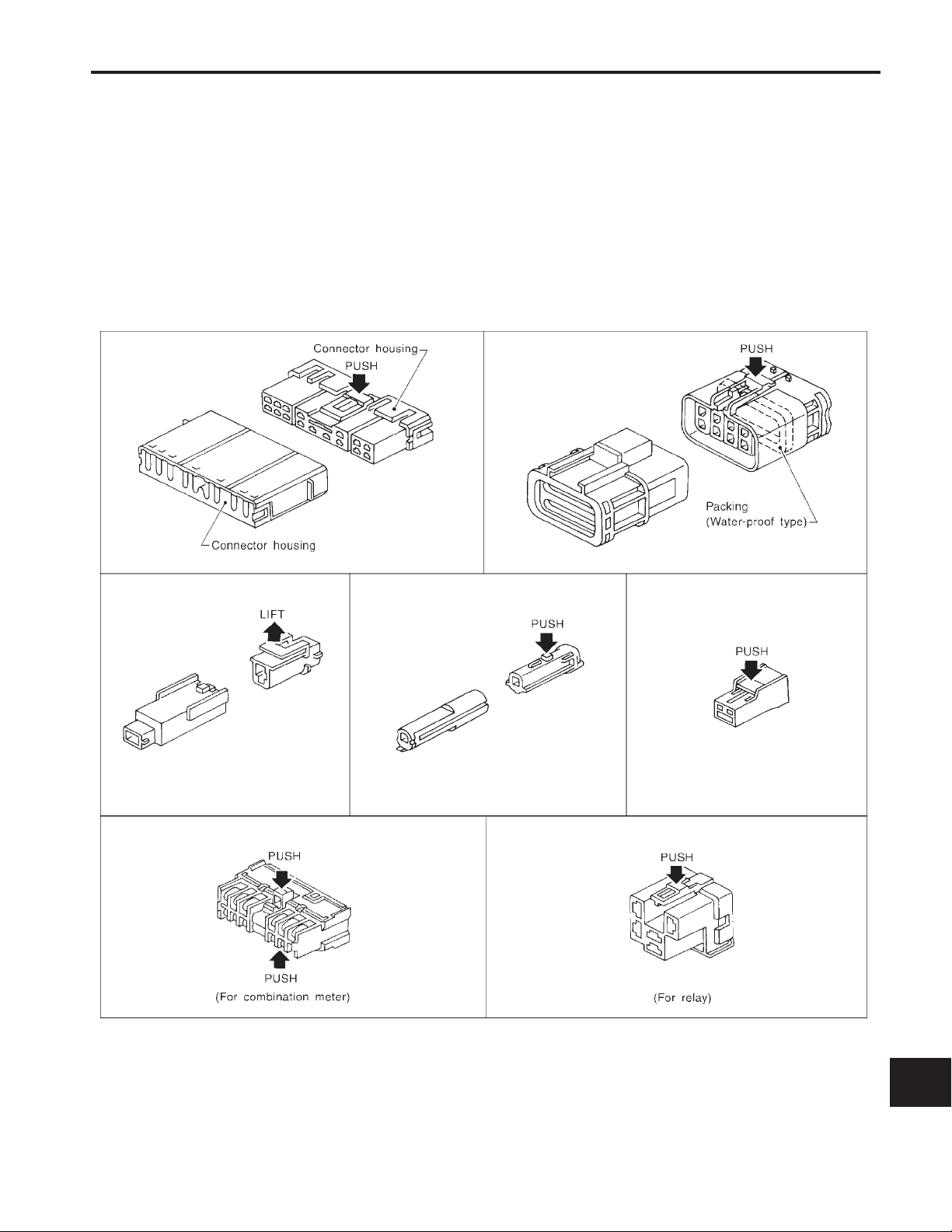
HARNESS CONNECTOR
Description
HARNESS CONNECTOR (TAB-LOCKING TYPE)
●
The tab-locking type connectors help prevent accidental looseness or disconnection.
●
The tab-locking type connectors are disconnected by pushing or lifting the locking tab(s). Refer to illustration below.
Refer to EL-6 for description of the slide-locking type connector.
CAUTION:
Do not pull the harness when disconnecting the connector.
[Example]
GI
MA
EM
LC
EC
FE
CL
MT
AT
TF
PD
FA
RA
BR
ST
RS
BT
HA
EL-5
EL
SEL769DA
IDX
HARNESS CONNECTOR
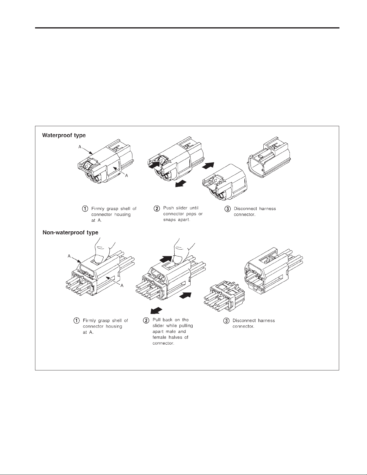
Description (Cont’d)
HARNESS CONNECTOR (SLIDE-LOCKING TYPE)
●
A new style slide-locking connector is used on certain systems and components, especially those related
to OBD.
●
The slide-locking type connectors help pervent incomplete locking and accidental looseness or disconnection.
●
The slide-locking type connectors are disconnected by pushing or pulling the slider. Refer to illustration
below.
CAUTION:
●
Do not pull the harness or wires when disconnecting the connector.
●
Be careful not to damage the connector support bracket when disconnecting the connector.
[Example]
EL-6
AEL299C
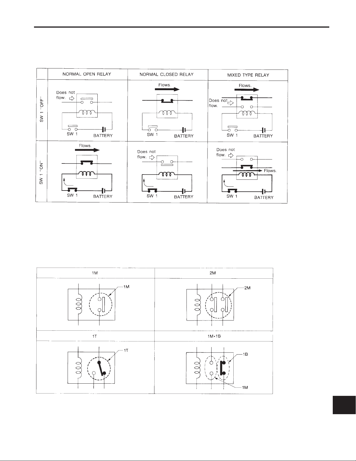
STANDARDIZED RELAY
Description
NORMAL OPEN, NORMAL CLOSED AND MIXED TYPE RELAYS
Relays can be divided into three main types: normal open, normal closed and mixed type relays.
GI
MA
EM
LC
EC
FE
CL
MT
AT
SEL881H
TYPES OF STANDARDIZED RELAYS
1M .................... 1 Make 2M .................... 2 Make
1T .................... 1 Transfer 1Mz1B .................... 1 Make 1 Break
TF
PD
FA
RA
BR
ST
RS
BT
HA
EL-7
SEL882H
EL
IDX
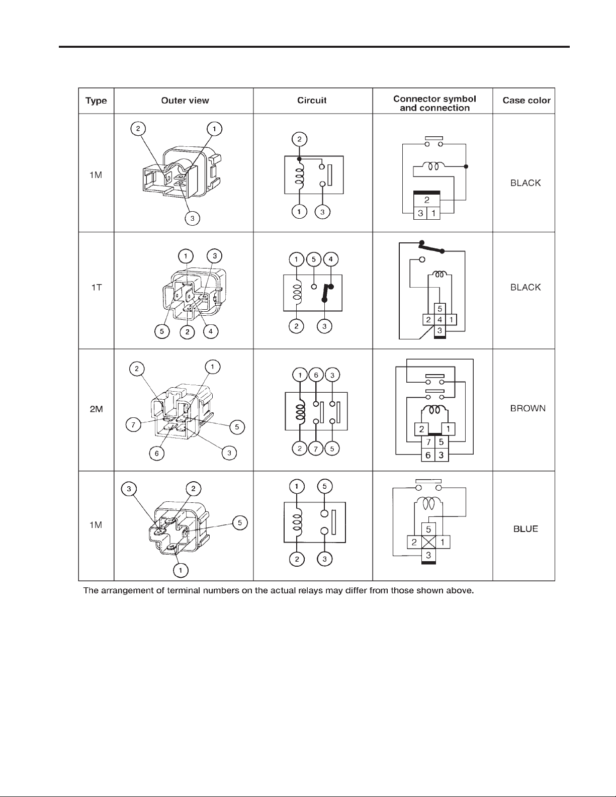
STANDARDIZED RELAY
Description (Cont’d)
EL-8
AEL672B
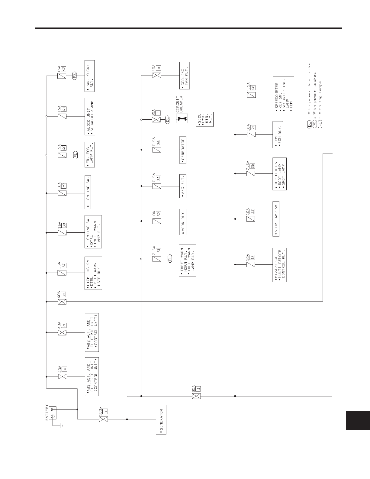
POWER SUPPLY ROUTING
Schematic
GI
MA
EM
LC
EC
FE
CL
MT
AT
TF
PD
FA
RA
BR
ST
RS
BT
HA
EL-9
EL
IDX
AEL580C
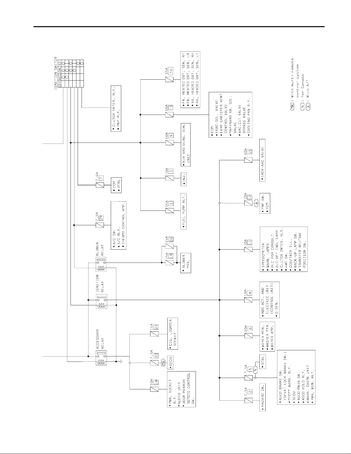
POWER SUPPLY ROUTING
Schematic (Cont’d)
EL-10
AEL581C
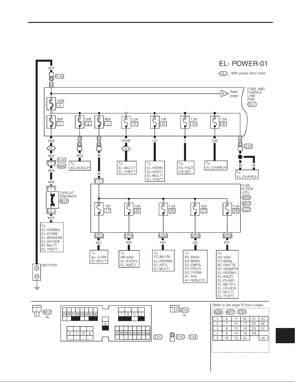
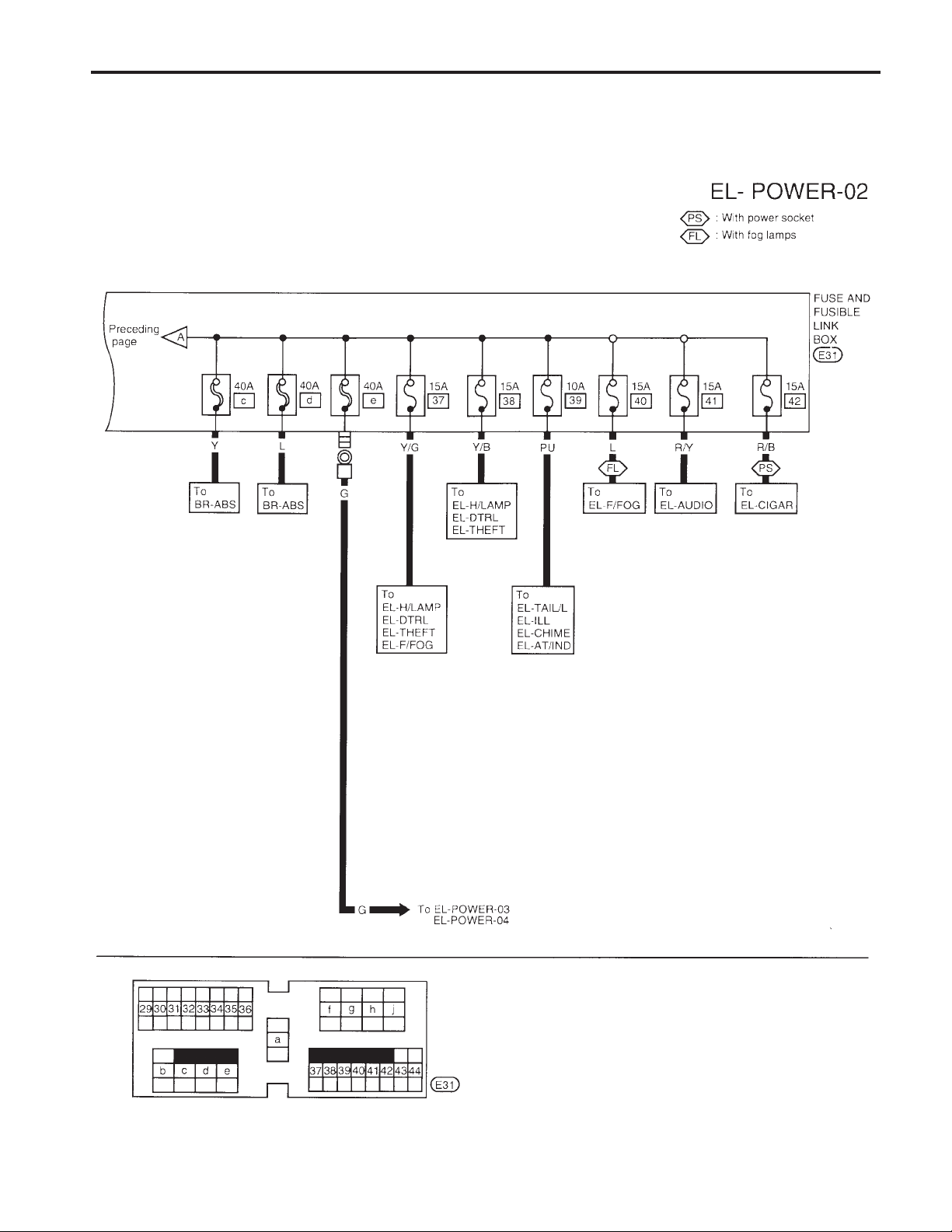
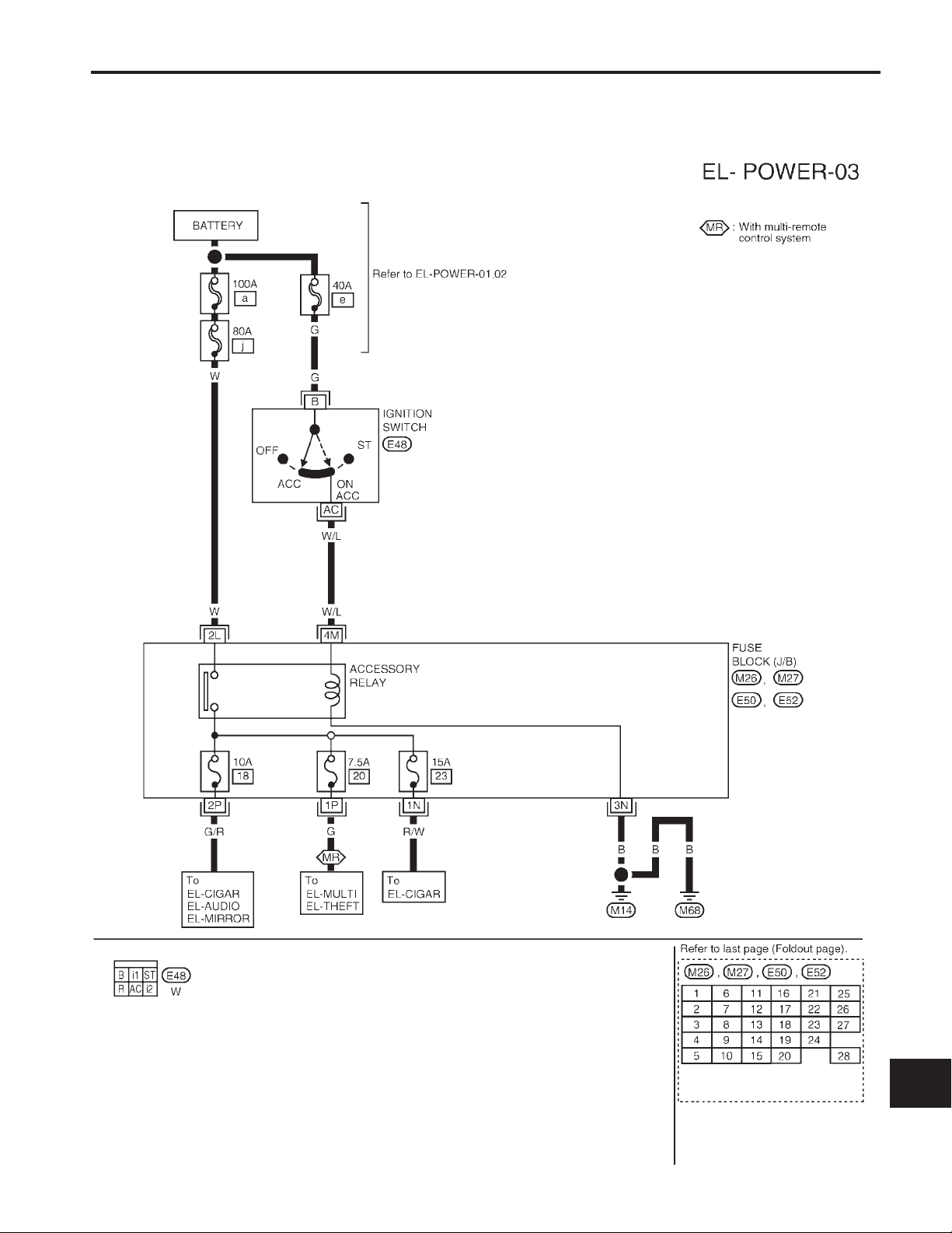
POWER SUPPLY ROUTING
Wiring Diagram — POWER —
BATTERY POWER SUPPLY – IGNITION SW IN ANY POSITION
NOTE: For detailed ground distribution information, refer to ‘‘GROUND DISTRIBUTION’’, EL-17.
GI
MA
EM
LC
EC
FE
CL
MT
AT
TF
PD
FA
RA
BR
ST
RS
BT
HA
EL-11
EL
IDX
AEL582C
POWER SUPPLY ROUTING
Wiring Diagram — POWER — (Cont’d)
EL-12
AEL264C
POWER SUPPLY ROUTING
Wiring Diagram — POWER — (Cont’d)
ACCESSORY POWER SUPPLY — IGNITION SW IN ‘‘ACC’’ OR ‘‘ON’’
NOTE: For detailed ground distribution information, refer to ‘‘GROUND DISTRIBUTION’’, EL-17.
GI
MA
EM
LC
EC
FE
CL
MT
AT
TF
PD
FA
RA
BR
ST
RS
BT
EL-13
HA
EL
IDX
AEL265C
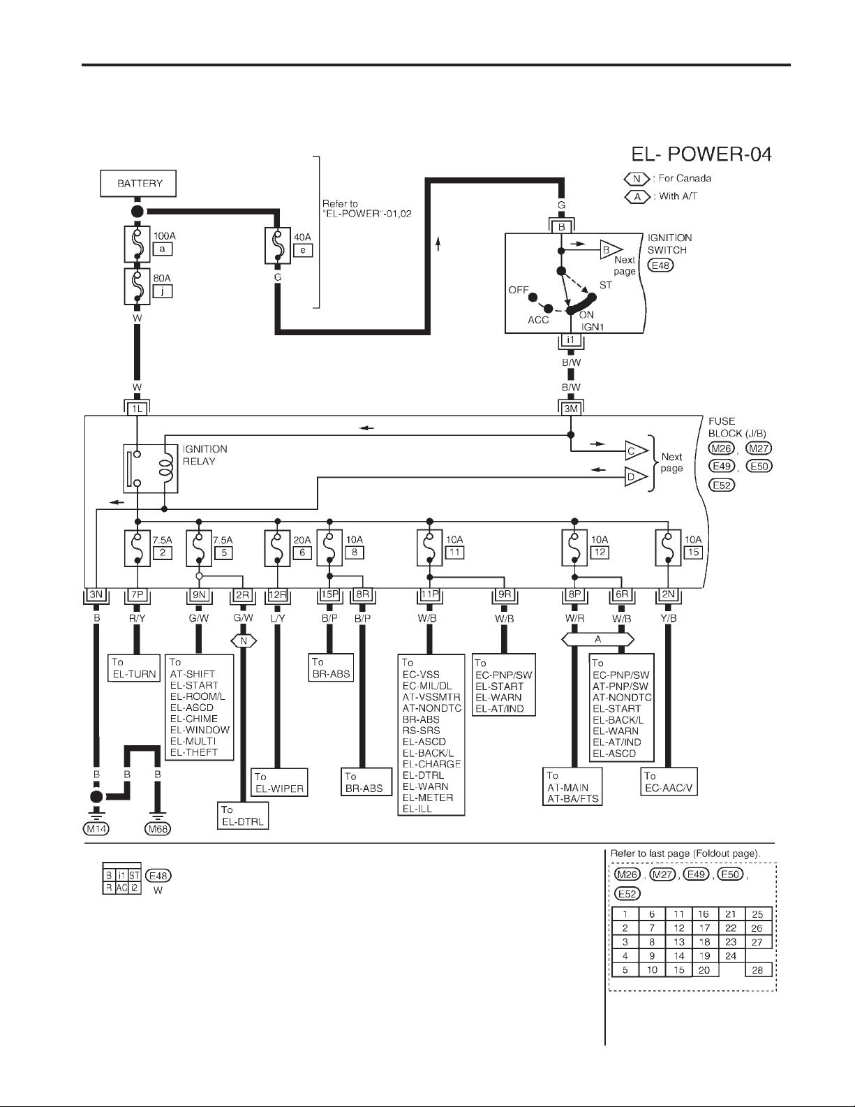
POWER SUPPLY ROUTING
Wiring Diagram — POWER — (Cont’d)
IGNITION POWER SUPPLY – IGNITION SW IN ‘‘ON’’AND/OR ‘‘START’’
NOTE: For detailed ground distribution information, refer to ‘‘GROUND DISTRIBUTION’’, EL-17.
EL-14
AEL266C
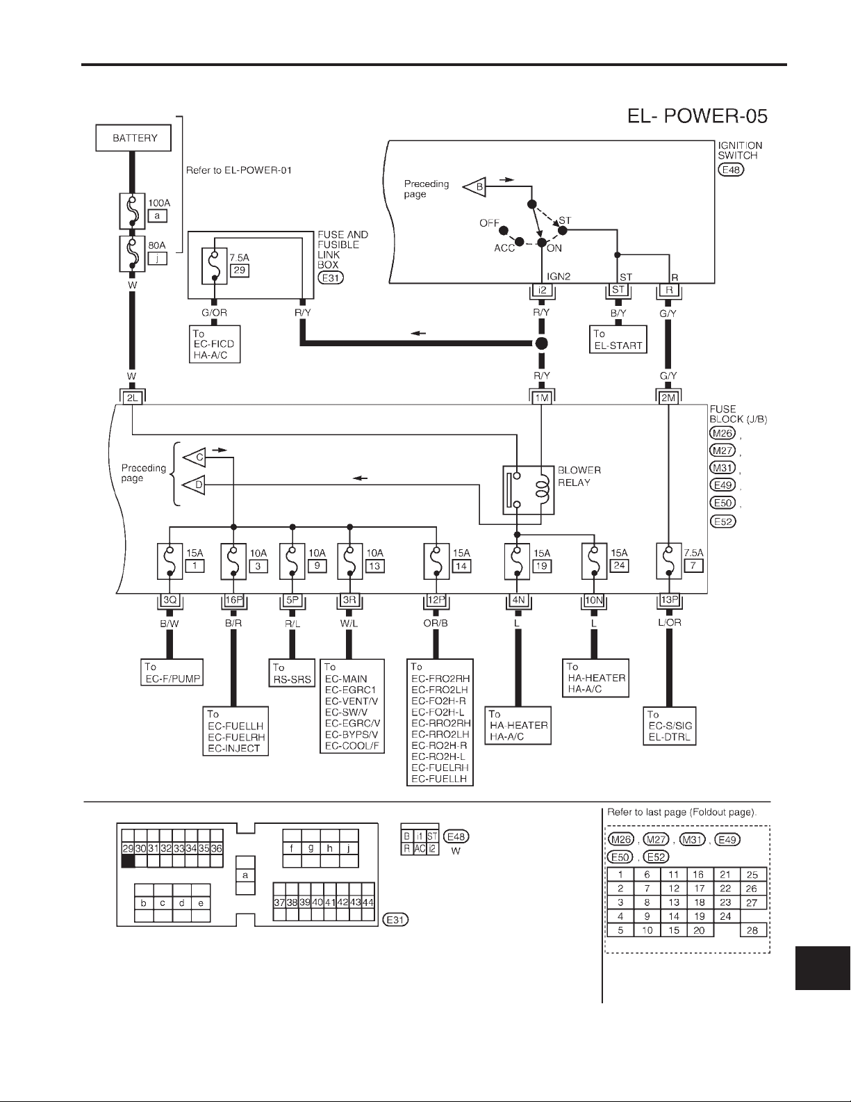
POWER SUPPLY ROUTING
Wiring Diagram — POWER — (Cont’d)
GI
MA
EM
LC
EC
FE
CL
MT
AT
TF
PD
FA
RA
BR
ST
RS
BT
EL-15
HA
EL
IDX
AEL267C
POWER SUPPLY ROUTING
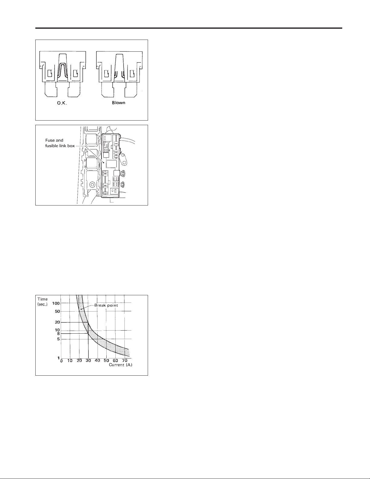
Fuse
a. If fuse is blown, be sure to eliminate cause of problem
before installing new fuse.
b. Use fuse of specified rating. Never use fuse of more than
specified rating.
c. Do not partially install fuse; always insert it into fuse
holder properly.
d. Remove fuse for ‘‘ELECTRICAL PARTS (BAT)’’ if vehicle is
not used for a long period of time.
SEL954J
Fusible Link
A melted fusible link can be detected either by visual inspection or
by feeling with finger tip. If its condition is questionable, use circuit
tester or test lamp.
CAUTION:
●
If fusible link should melt, it is possible that critical circuit
(power supply or large current carrying circuit) is shorted.
In such a case, carefully check and eliminate cause of
problem.
●
Never wrap outside of fusible link with vinyl tape. Impor-
AEL600B
tant: Never let fusible link touch any other wiring harness,
vinyl or rubber parts.
SBF284E
Circuit Breaker Inspection
For example, when current is 30A, the circuit is broken within 8 to
20 seconds.
EL-16
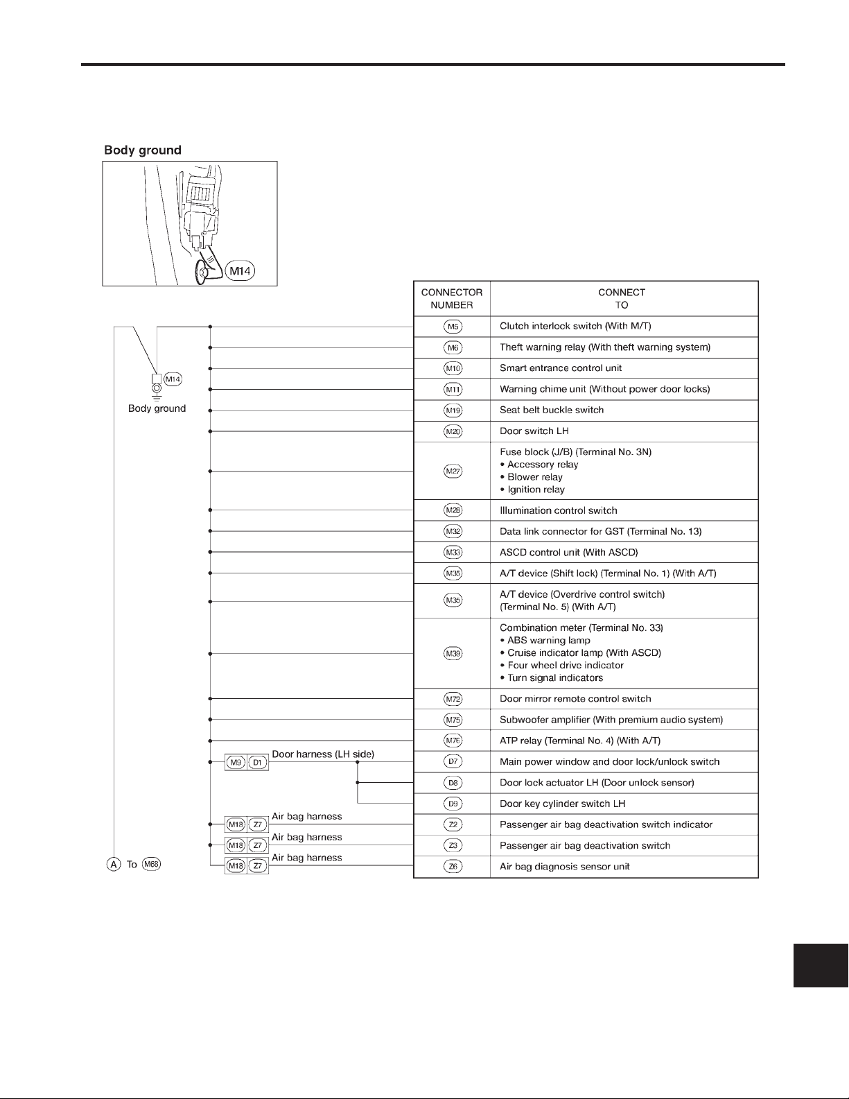
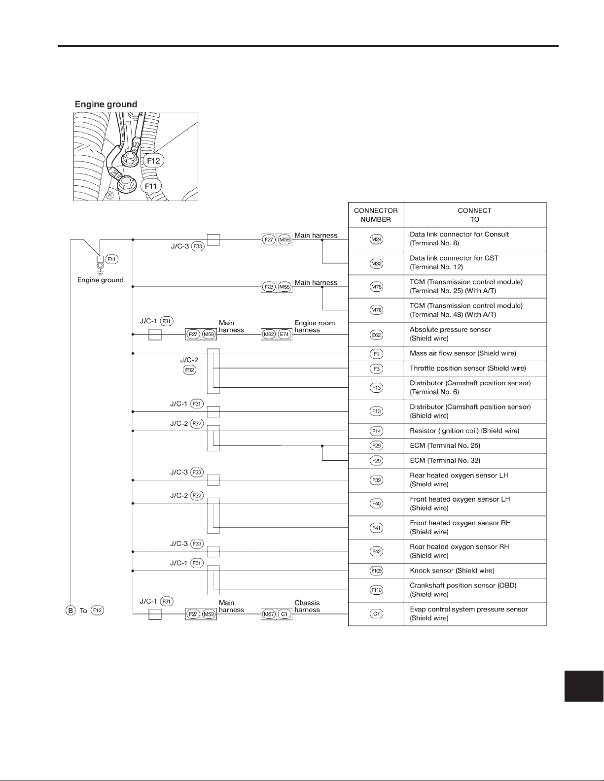
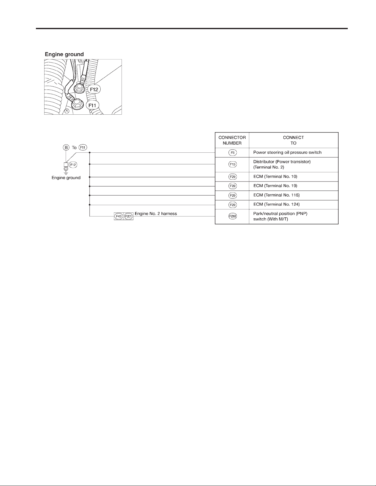
GROUND DISTRIBUTION
Main Harness
GI
MA
EM
LC
EC
FE
CL
MT
AT
TF
PD
FA
RA
BR
ST
RS
BT
HA
EL-17
EL
IDX
AEL300C
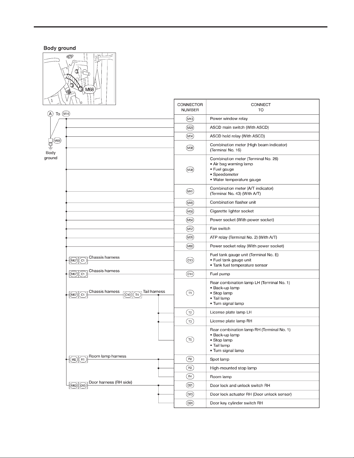
GROUND DISTRIBUTION
Main Harness (Cont’d)
EL-18
AEL301C
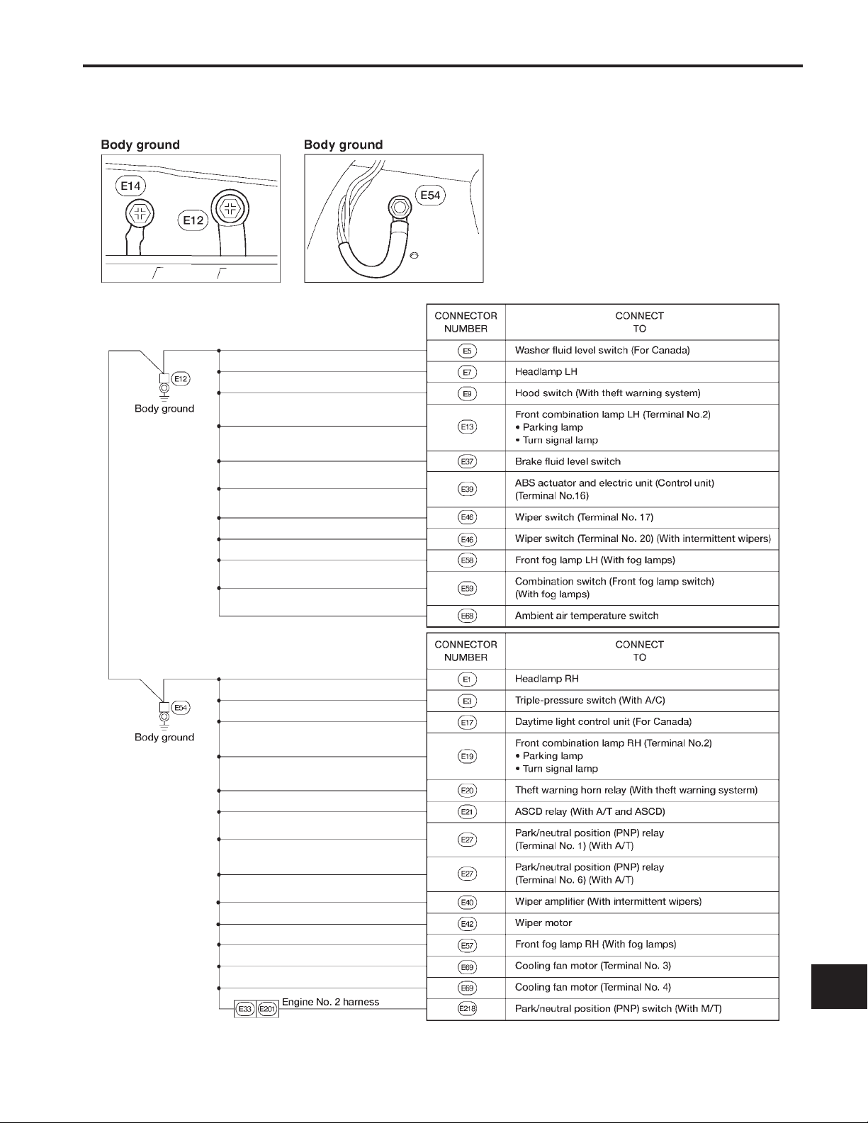
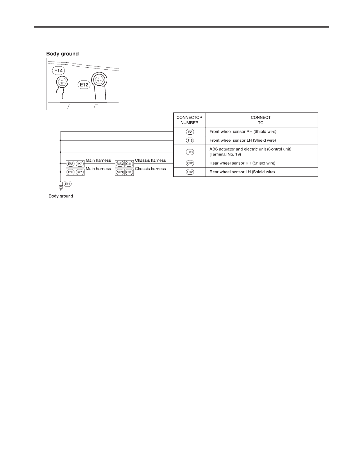
GROUND DISTRIBUTION
Engine Room Harness
GI
MA
EM
LC
EC
FE
CL
MT
AT
TF
PD
FA
RA
BR
ST
RS
BT
HA
EL-19
EL
IDX
AEL302C
GROUND DISTRIBUTION
Engine Room Harness (Cont’d)
EL-20
AEL303C
GROUND DISTRIBUTION
Engine Control Harness
GI
MA
EM
LC
EC
FE
CL
MT
AT
TF
PD
FA
RA
BR
ST
RS
BT
HA
EL-21
EL
IDX
AEL304C
GROUND DISTRIBUTION
Engine Control Harness (Cont’d)
EL-22
AEL305C
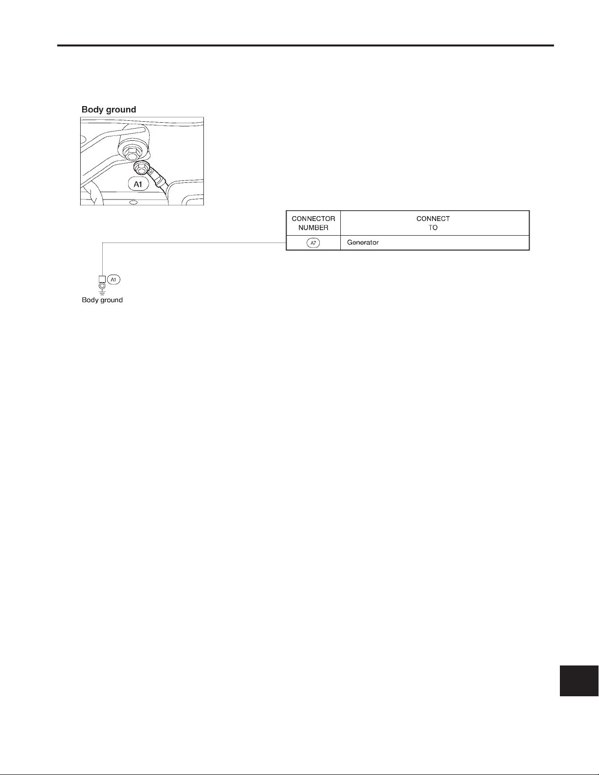
GROUND DISTRIBUTION
Generator Harness
GI
MA
EM
LC
EC
FE
CL
MT
AT
TF
PD
FA
RA
BR
ST
RS
BT
HA
EL-23
EL
IDX
AEL306C
BATTERY
CAUTION:
If it becomes necessary to start the engine with a booster
battery and jumper cables:
●
Use a 12-volt booster battery.
●
After connecting battery cables, ensure that they are
tightly clamped to battery terminals for good contact.
●
Never add distilled water through the hole used to check
specific gravity.
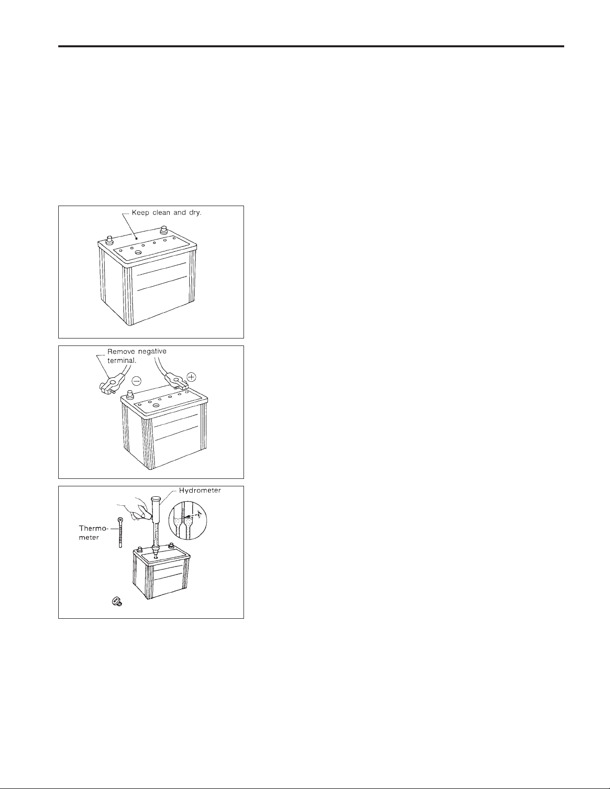
How to Handle Battery
METHODS OF PREVENTING OVER-DISCHARGE
The following precautions must be taken to prevent over-discharging a battery.
●
The battery surface (particularly its top) should always be kept
clean and dry.
●
The terminal connections should be clean and tight.
●
At every routine maintenance, check the electrolyte level.
SEL711E
SEL712E
SEL459R
●
When the vehicle is not going to be used over a long period of
time, disconnect the negative battery terminal. (If the vehicle
has an extended storage switch, turn it off.)
●
Check the charge condition of the battery.
Periodically check the specific gravity of the electrolyte. Keep
a close check on charge condition to prevent overdischarge.
EL-24
BATTERY
How to Handle Battery (Cont’d)
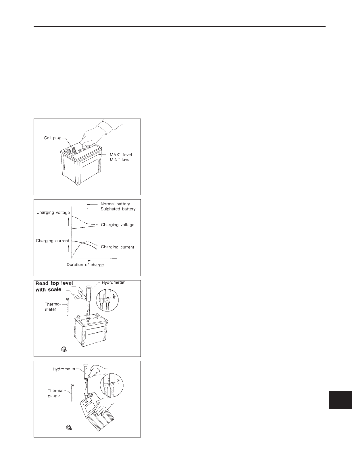
CHECKING ELECTROLYTE LEVEL
WARNING:
Do not allow battery fluid to come in contact with skin, eyes,
fabrics, or painted surfaces. After touching a battery, do not
touch or rub youreyes until you have thoroughly washed your
hands. If the acid contacts the eyes, skin or clothing, immediately flush with water for 15 minutes and seek medical attention.
Normally the battery does not require additional water.
However, when the battery is used under severe conditions,
adding distilled water may be necessary during the battery life.
GI
MA
EM
LC
SEL001K
SEL005Z
●
Remove the cell plug using a suitable tool.
●
Add distilled water up to the MAX level.
SULPHATION
A battery will be completely discharged if it is left unattended for a
long time and the specific gravity becomes less than 1.100. This
may result in sulphation on the cell plates.
To determineif a battery has been‘‘sulphated’’, note its voltageand
current when charging it. As shown in the figure, less current and
higher voltage are observed in the initial stage of charging sulphated batteries.
A sulphated battery may sometimes be brought back into service
by means of a long, slow charge, 12 hours or more, followed by a
battery capacity test.
SPECIFIC GRAVITY CHECK
1. Read hydrometer and thermometer indications at eye level.
EC
FE
CL
MT
AT
TF
PD
FA
RA
BR
SEL442D
SEL006Z
●
When electrolyte level is too low, tilt battery case to raise it for
easy measurement.
EL-25
ST
RS
BT
HA
EL
IDX

BATTERY
How to Handle Battery (Cont’d)
2. Use the chart below to correct your hydrometer reading
according to electrolyte temperature.
Hydrometer temperature correction
Battery electrolyte temperature °C (°F) Add to specific gravity reading
71 (160) 0.032
66 (150) 0.028
60 (140) 0.024
54 (129) 0.020
49 (120) 0.016
43 (110) 0.012
38 (100) 0.008
32 (90) 0.004
27 (80) 0
21 (70) −0.004
16 (60) −0.008
10 (50) −0.012
4 (39) −0.016
−1 (30) −0.020
−7 (20) −0.024
−12 (10) −0.028
−18 (0) −0.032
Corrected specific gravity Approximate charge condition
1.260 - 1.280 Fully charged
1.230 - 1.250 3/4 charged
1.200 - 1.220 1/2 charged
1.170 - 1.190 1/4 charged
1.140 - 1.160 Almost discharged
1.110 - 1.130 Completely discharged
EL-26

BATTERY
How to Handle Battery (Cont’d)
CHARGING THE BATTERY
CAUTION:
●
Do not ‘‘quick charge’’ a fully discharged battery.
●
Keep the battery away from open flame while it is being
charged.
●
When connecting the charger, connectthe leads first, then
turn on the charger. Do not turn on the charger first, as
this may cause a spark.
●
If battery electrolyte temperature rises above 60°C (140°F),
stop charging. Always charge battery at a temperature
below 60°C (140°F).
Charging rates
Amps Time
GI
MA
EM
LC
EC
50
25
10
5
Do not charge at more than 50 ampere rate.
Note: The ammeter reading on your battery charger will auto-
matically decrease as the battery charges. This indicates that the voltage of the battery is increasing normally as the state of charge improves. The charging
amps indicated above refer to initial charge rate.
●
If, after charging, the specific gravity of any two cells varies
more than .050, the battery should be replaced.
●
After the battery is charged, always perform a capacity test to
assure that the battery is serviceable.
1 hour
2 hours
5 hours
10 hours
Service Data and Specifications (SDS)
Applied area USA Canada
Type 55D23R 65D26R
Capacity V-AH 12-60 12-65
Cold cranking current A
(For reference value)
356 413
FE
CL
MT
AT
TF
PD
FA
RA
BR
EL-27
ST
RS
BT
HA
EL
IDX

STARTING SYSTEM
System Description
M/T MODELS
Power is supplied at all times:
●
through 40A fusible link (letter , located in the fuse and fusible link box)
●
to ignition switch terminal
With the ignition switch in the START position, power is supplied:
●
through terminal
●
to clutch interlock relay terminal
ST
s
For models with theft warning system
With the ignition switch in the ON or START position, power is supplied:
●
through 7.5A fuse [No. , located in the fuse block (J/B)]
●
to theft warning relay terminal
With the ignition switch in the ON or START position, power is supplied:
●
through 10A fuse [No. , located in the fuse block (J/B)]
●
to clutch interlock relay terminal
If the theft warning system is triggered, terminal
of the smart entrance control unit and ground to the clutch interlock relay is interrupted.
When the theft warning system is not operating and clutch pedal is depressed, ground is supplied:
●
from clutch interlock switch terminal
●
to theft warning relay terminal
●
through theft warning relay terminal
●
to clutch interlock relay terminal
For models without theft warning system
With the ignition switch in the ON or START position, power is supplied:
●
through 10A fuse [No. , located in the fuse block (J/B)]
●
to clutch interlock relay terminal
When the clutch pedal is depressed, ground is supplied:
●
from clutch interlock switch terminal
●
to clutch interlock relay terminal
B
.
s
of the ignition switch
5
.
s
2
.
s
2
.
s
2
s
3
s
1
s
2
s
1
s
4
s
.
.
2
s
.
1
of the theft warning relay is grounded through terminal
s
32
s
Ground is supplied to clutch interlock switch terminal
1
through body grounds
s
s
M14
and
s
M68
.
The clutch interlock relay is energized and power is supplied:
●
from terminal
●
to terminal
3
of the clutch interlock relay
s
1
of the starter motor windings.
s
The starter motor plunger closes and provides a closed circuit between the battery and the starter motor. The
starter motoris grounded to theengine block. With powerand ground supplied, crankingoccurs and the engine
starts.
EL-28

STARTING SYSTEM
System Description (Cont’d)
A/T MODELS
Power is supplied at all times:
●
through 40A fusible link (letter , located in the fuse and fusible link box)
●
to ignition switch terminal
With the ignition switch in the START position, power is supplied:
●
through terminal
●
to park/neutral position (PNP) relay terminal
ST
s
For models with theft warning system
With the ignition switch in the ON or START position, power is supplied:
●
through 7.5A fuse [No. , located in the fuse block (J/B)]
●
to theft warning relay terminal
With the ignition switch in the ON or START position, power is supplied:
●
through 10A fuse [No. , located in the fuse block (J/B)]
●
to PNP switch terminal
With the selector lever in the P or N position, power is supplied:
●
from PNP switch terminal
●
to PNP relay terminal
If the theft warning system is triggered, terminal
of the smart entrance control unit and ground to the PNP relay is interrupted.
When the theft warning system is not operating, ground is supplied:
●
from theft warning relay terminal
●
through theft warning relay terminal
●
to PNP relay terminal
For models without theft warning system
With the ignition switch in the ON or START position, power is supplied:
●
through 10A fuse [No. , located in the fuse block (J/B)]
●
to PNP switch terminal
With the selector lever in the P or N position, power is supplied:
●
from PNP switch terminal
●
to PNP relay terminal
B
.
s
of the ignition switch
2
.
s
1
.
s
2
s
2
.
s
3
s
4
1
s
2
s
1
s
.
.
2
s
.
s
5
.
s
1
of the theft warning relay is grounded through terminal
s
32
s
GI
MA
EM
LC
EC
FE
CL
MT
AT
TF
PD
1
Ground is supplied to PNP relay terminal
The PNP relay is energized and power is supplied:
●
from terminal
●
to terminal
The starter motor plunger closes and provides a closed circuit between the battery and the starter motor. The
starter motoris grounded to theengine block. With powerand ground supplied, crankingoccurs and the engine
starts.
3
of the PNP relay
s
1
of the starter motor windings.
s
through body grounds
s
s
E12
and
s
E54
.
THEFT WARNING SYSTEM
The theft warning system will interrupt ground to clutch interlock relay (M/T models) or PNP relay (A/T models) if the system is triggered. The starter motor will then not crank, and the engine will not start. Refer to
‘‘THEFT WARNING SYSTEM’’ (EL-189).
FA
RA
BR
ST
RS
BT
HA
EL
IDX
EL-29
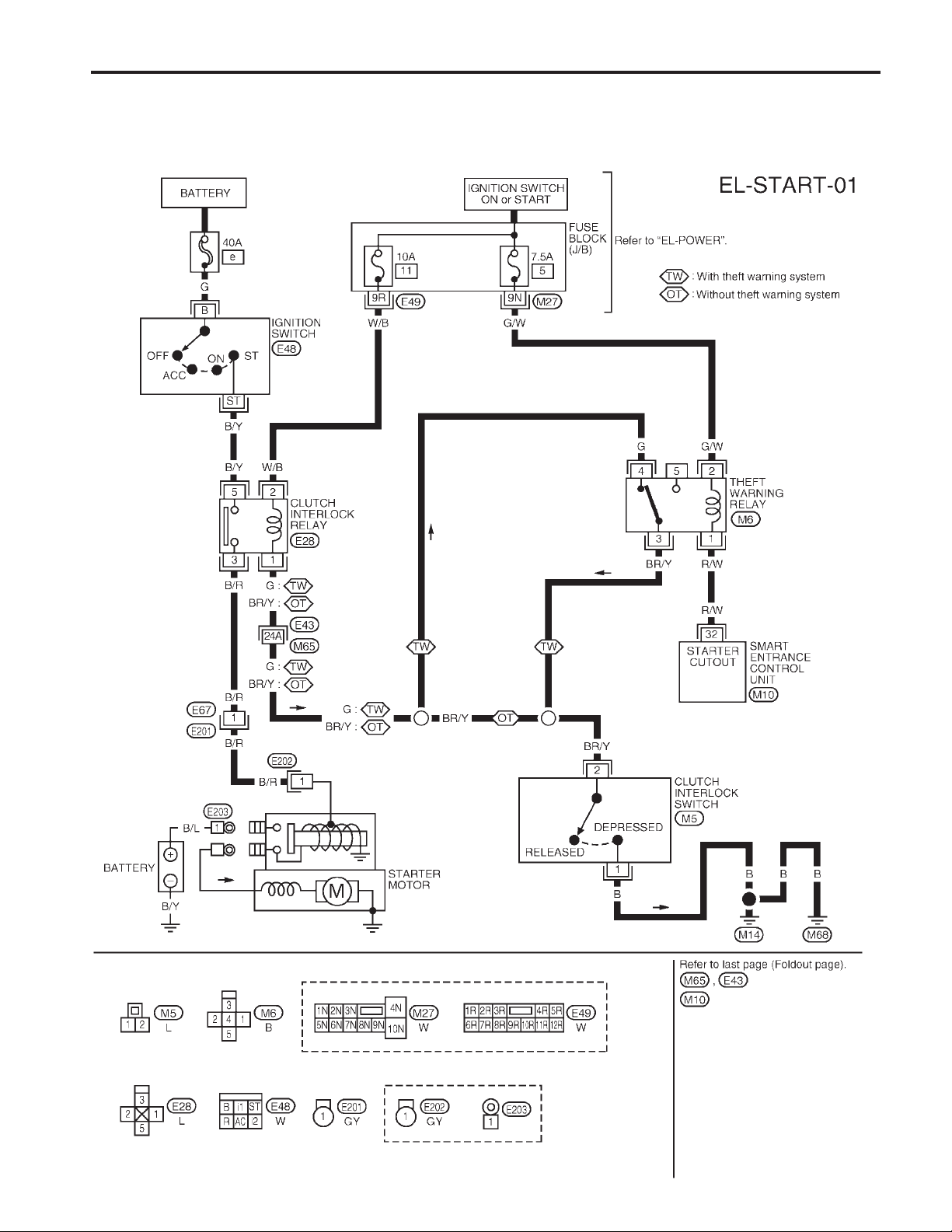
M/T MODELS
STARTING SYSTEM
Wiring Diagram — START —
EL-30
AEL268C

A/T MODELS
STARTING SYSTEM
Wiring Diagram — START — (Cont’d)
GI
MA
EM
LC
EC
FE
CL
MT
AT
TF
PD
FA
RA
BR
ST
RS
BT
EL-31
HA
EL
IDX
AEL269C

STARTING SYSTEM
Construction
1
Gear case
s
2
Shift lever
s
3
Plate
s
4
Packing
s
5
Adjusting plate
s
6
Magnetic switch assembly
s
7
Pinion stopper set
s
8
Pinion assembly
s
9
Internal gear
s
10
Pinion shaft
s
11
Planetary gear
s
EL-32
12
Packing
s
13
Yoke
s
14
Armature
s
15
Brush holder assembly
s
16
Rear cover
s
AEL147C

STARTING SYSTEM
AEL148C
Removal and Installation
REMOVAL
1. Remove engine undercover.
2. Remove two bolts and starter.
INSTALLATION
To install, reverse the removal procedure.
Pinion/Clutch Check
1. Inspect pinion teeth.
●
Replace pinion if teeth are worn or damaged. (Also check
condition of ring gear teeth.)
2. Inspect reduction gear teeth.
●
Replace reduction gear if teeth are worn or damaged. (Also
check condition of armature shaft gear teeth.)
3. Check to see if pinion locks in one direction and rotates
smoothly in the opposite direction.
●
If it locks or rotates in both directions, or unusual resistance is
evident, replace.
Service Data and Specifications (SDS)
STARTER
M000T60185ZC
Type
System voltage V 12
No-load
Terminal voltage V 11.0
Current A 90 Max.
Motor revolution rpm 2,500 Min.
Minimum diameter of
commutator
mm (in)
Minimum length of brush
mm (in)
Brush spring tension
N (kg, lb)
Clearance of bearing metal and armature
shaft
mm (in)
Clearance between pinion front edge and
pinion stopper
mm (in)
MITSUBISHI
Reduction
28.8 (1.134)
7.0 (0.276)
11.8 - 23.5
(1.20 - 2.40, 2.65 - 5.28)
0.2 (0.008)
0.5 - 2.0
(0.020 - 0.079)
GI
MA
EM
LC
EC
FE
CL
MT
AT
TF
PD
FA
RA
BR
ST
RS
BT
EL-33
HA
EL
IDX

CHARGING SYSTEM
System Description
The generator provides DC voltage to operate the vehicle’s electrical system and to keep the battery charged.
The voltage output is controlled by the IC regulator.
Power is supplied at all times to generator terminal
●
100A fusible link (letter , located in the fuse and fusible link box), and
●
7.5A fuse (No. , located in the fuse and fusible link box).
Terminal
is controlled by the IC regulator at terminal
the 100A fusible link.
Terminal
With the ignition switch in the ON or START position, power is supplied:
●
●
Ground is supplied to terminal
and ground supplied, the charge warning lamp will illuminate. When the generator is providing sufficient voltage with the engine running, the ground is opened and the charge warning lamp will not illuminate.
If the charge warning lamp illuminates with the engine running, a fault is indicated.
1
supplies power to charge the battery and operate the vehicle’s electrical system. Output voltage
s
2
of the generator supplies ground through body ground
s
through 10A fuse [No. , located in the fuse block (J/B)]
to combination meter terminal
29
s
27
of the combination meter through terminal
s
4
detecting the input voltage. The charging circuit is protected by
s
for the charge warning lamp.
4
s
through:
s
A1 .
3
of the generator. With power
s
EL-34

CHARGING SYSTEM
Wiring Diagram — CHARGE —
GI
MA
EM
LC
EC
FE
CL
MT
AT
TF
PD
FA
RA
BR
ST
RS
BT
HA
EL-35
EL
IDX
AEL584C

CHARGING SYSTEM
Trouble Diagnoses
Before conducting a generator test, make sure that the battery is fully charged. A 30-volt voltmeter and suitable test probes are necessary for the test. The generator can be checked easily by referring to the Inspection Table.
●
Before starting, inspect the fusible link.
●
Use fully charged battery.
WITH IC REGULATOR
Check the following:
●
Ignition switch
‘‘ON’’
Warning lamp
‘‘OFF’’
Disconnect connector (S, L) and
ground L harness side.
Warning lamp
‘‘OFF’’
Warning
lamp bulb
●
Fuse for
warning lamp
Warning lamp
‘‘ON’’
Engine idling Warning lamp
Warning lamp
‘‘OFF’’
Warning lamp: ‘‘CHARGE’’ warning lamp in combination meter
‘‘ON’’
OK Engine speed:
Check the following:
●
Drive belt
●
B terminal connection
(Check the tightening torque)
●
Fuse for S terminal
●
Connector (S, L terminal) connection
Warning lamp
‘‘ON’’
Engine idling Warning lamp
Warning lamp
‘‘ON’’
1,500 rpm
(Measure B
terminal voltage)
‘‘OFF’’
More than
15.5V
No generation Field circuit is
Damaged IC
regulator.
Replace.
OK
Damaged IC
regulator.
Replace.
open.*
Note:
.: When field circuit is open, check condition of rotor coil, rotor slip ring and brush. If necessary,
replace faulty parts with new ones.
MALFUNCTION INDICATOR
The IC regulator warning function activates to illuminate ‘‘CHARGE’’ warning lamp, if any of the following
symptoms occur while generator is operating:
●
Excessive voltage is produced.
●
No voltage is produced.
EL-36

CHARGING SYSTEM
Construction
GI
MA
EM
LC
EC
FE
CL
MT
AT
1
Pulley assembly
s
2
Front cover
s
3
Front bearing
s
4
Retainer
s
5
s
6
s
7
s
8
s
Rotor
Slip ring
Stator
Fan guide
9
IC regulator assembly
s
10
Diode assembly
s
11
Packing
s
12
Rear cover
s
AEL149C
TF
PD
FA
RA
BR
ST
RS
BT
HA
EL-37
EL
IDX

AEL421C
CHARGING SYSTEM
Removal and Installation
REMOVAL
1. Disconnect harness connectors.
2. Remove engine undercover.
3. Back off adjustment bolt, remove belt.
4. Remove 3 generator bolts and generator.
INSTALLATION
To install, reverse the removal procedure.
Service Data and Specifications (SDS)
GENERATOR
Type
Nominal rating V-A 12-70
Ground polarity Negative
Minimum revolution under no-load
(When 13.5 volts is applied) rpm
Hot output current
(When 13.5 volts is applied) A/rpm
Regulated output voltage V 14.1 - 14.7
Minimum length of brush mm (in) 6.00 (0.236)
Brush spring pressure N (g, oz) 1.000 - 2.452 (102 - 250, 3.60 - 8.82)
Slip ring minimum diameter mm (in) 26.0 (1.024)
Rotor (field coil) resistance V 2.7
LR180-756
HAP
Less than 1,000
More than 23/1,300
More than 65/2,500
More than 77/5,000
EL-38

COMBINATION SWITCH
Check
GI
MA
EM
LC
EC
FE
CL
MT
AT
TF
PD
FA
RA
BR
ST
RS
BT
HA
EL-39
EL
IDX
AEL122C

COMBINATION SWITCH
Replacement
For removal andinstallation of spiral cable, referto RS section
[‘‘Driver Air Bag Module and Spiral Cable’’, ‘‘SUPPLEMENTAL
RESTRAINT SYSTEM (SRS)’’].
●
Each switch can be replaced without removing combination
switch base.
SEL865L
●
To remove combination switch base, remove base attaching
screws.
MEL205B
ARS152
●
Before installing the steering wheel, align the turn signal cancel tab with the notch of combination switch. Refer to RS section (‘‘INSTALLATION’’, ‘‘Driver Air Bag Module and Spiral
Cable’’).
EL-40

STEERING SWITCH
Check
GI
MA
EM
LC
EC
FE
CL
MT
AT
TF
PD
FA
RA
BR
ST
RS
BT
HA
EL-41
EL
IDX
AEL603B

HEADLAMP
System Description (For USA)
The headlamps are controlled by the lighting switch which is built into the combination switch.
Power is supplied at all times:
●
to lighting switch terminal
●
through 15A fuse (No. , located in the fuse and fusible link box), and
●
to lighting switch terminal
●
through 15A fuse (No. , located in the fuse and fusible link box).
Low beam operation
When the lighting switch is turned to headlamp ON (2ND) position, LOW BEAM (B), power is supplied:
●
from lighting switch terminal
●
to terminal
●
from lighting switch terminal
●
to terminal
Terminal
With power and ground supplied, the headlamp(s) will illuminate.
s
D
of the LH headlamp, and
s
D
of the RH headlamp.
s
E
of each headlamp supplies ground through body grounds
High beam operation/flash-to-pass operation
When the lighting switch is turned to headlamp ON (2ND) position, HIGH BEAM (A) or FLASH TO PASS (C)
position, power is supplied:
●
from lighting switch terminal
●
to terminal
●
from lighting switch terminal
●
to terminal
●
to combination meter terminal
Ground is supplied to terminal
Terminal
With power and ground supplied, the high beams and the high beam indicator illuminate.
Theft warning system
The theft warning system will flash the high beams if the system is triggered. Refer to ‘‘THEFT WARNING
SYSTEM’’ (EL-189).
s
M
of RH headlamp, and
s
M
of LH headlamp, and
s
E
of each headlamp supplies ground through body grounds
5
s
8
s
10
s
7
s
s
6
s
9
s
17
for the high beam indicator.
s
16
of the combination meter through body grounds
s
s
E12
E12
and
and
s
s
s
E54
M14
E54
.
.
and
s
M68
.
EL-42

HEADLAMP
Wiring Diagram (For USA) — H/LAMP —
GI
MA
EM
LC
EC
FE
CL
MT
AT
TF
PD
FA
RA
BR
ST
RS
BT
HA
EL-43
EL
IDX
AEL271C

Symptom Possible cause Repair order
LH headlamp does not operate. 1. Bulb
2. Grounds
3. 15A fuse
4. Lighting switch
RH headlamp does not operate. 1. Bulb
2. Grounds
3. 15A fuse
4. Lighting switch
LH high beam does not operate, but
LH low beam operates.
LH low beam does not operate, but
LH high beam operates.
RH high beam doesnot operate,but
RH low beam operates.
RH low beam does not operate, but
RH high beam operates.
High beam indicator does not work. 1. Bulb
1. Bulb
2. Open in LH high beam circuit
3. Lighting switch
1. Bulb
2. Open in LH low beam circuit
3. Lighting switch
1. Bulb
2. Open in RH high beam circuit
3. Lighting switch
1. Bulb
2. Open in RH low beam circuit
3. Lighting switch
2. Grounds
3. Open in high beam circuit
HEADLAMP
Trouble Diagnoses
1. Check bulb.
s
s
s
E12
E12
M14
and
and
and
s
s
s
E54
E54
M68
2. Check grounds
3. Check 15A fuse (No.
link box). Verify battery positive voltage is present at
terminal
4. Check lighting switch.
1. Check bulb.
2. Check grounds
3. Check 15A fuse (No.
link box). Verify battery positive voltage is present at
terminal
4. Check lighting switch.
1. Check bulb.
2. Check R/G wire between lighting switch and LH headlamp for an open circuit.
3. Check lighting switch.
1. Check bulb.
2. Check R wire between lighting switch and LH headlamp for an open circuit.
3. Check lighting switch.
1. Check bulb.
2. Check R/Wwire betweenlighting switch and RH headlamp for an open circuit.
3. Check lighting switch.
1. Check bulb.
2. Check R/B wire between lighting switch and RH headlamp for an open circuit.
3. Check lighting switch.
1. Check bulb in combination meter.
2. Check grounds
3. Check R/G wire between lighting switch and combination meter for an open circuit.
E12
s
8
of lighting switch.
s
E12
s
5
of lighting switch.
s
M14
s
E54
and
, located in fuse and fusible
and
, located in fuse and fusible
and
s
s
s
E54
M68
.
.
.
EL-44

HEADLAMP
AEL599B
Bulb Replacement
The headlamp is a semi-sealed beam type which uses a replaceable halogen bulb. The bulb can be replaced from the engine compartment side without removing the headlamp body.
●
Grasp only the plasticbase when handling the bulb. Never
touch the glass envelope.
1. Disconnect the battery cable.
2. Disconnect the harness connector from the back side of the
bulb.
3. Unclip the bulb retaining clip, and then remove it.
4. Remove the headlamp bulb carefully. Do not shake or rotate
the bulb when removing it.
5. Install in the reverse order of removal.
CAUTION:
●
Do not leave headlamp reflector without bulb for a long
period of time. Dust, moisture, smoke, etc. entering headlamp body may affect the performance of the headlamp.
Remove headlamp bulb from the headlamp reflector just
before a replacement bulb is installed.
Aiming Adjustment
When performing headlamp aiming adjustment, use an aiming
machine, aiming wall screen or headlamp tester. Aimers should be
in good repair, calibrated and operated in accordance with respective operation manuals.
If any aimer is not available, aiming adjustment can be done as
follows:
For details, refer to the regulations in your own country.
a. Keep all tires inflated to correct pressures.
b. Place vehicle and tester on one and same flat surface.
c. See that there is no-load in vehicle (coolant, engine oil
filled up to correct level and full fuel tank) other than the
driver (or equivalent weight placed in driver’s position).
GI
MA
EM
LC
EC
FE
CL
MT
AT
TF
PD
FA
RA
BR
ST
RS
BT
HA
EL
IDX
EL-45

AEL601B
HEADLAMP
Aiming Adjustment (Cont’d)
AIMER ADJUSTMENT MARK
When using a mechanical aimer, adjust adapter legs to the data
marked on the headlamps.
Adjustment value for mechanical aimer
Mechanical aimer level
Horizontal side −4 to 4
Vertical side −4 to 4
LOW BEAM
1. Turn headlamp low beam on.
2. Use a
lamp.
●
Cover the opposite lamp.
#
2 cross-recessed screwdriver to adjust the aim of the
AEL671B
SEL866L
If the vehicle front body has been repaired and/or the headlamp
assembly has been replaced, check aiming. Use the aiming chart
shown in the figure.
●
Upper edge and left edge of high intensity zone should be
within the range shown at left. Adjust headlamps accordingly.
●
Dotted lines in illustration show center of headlamp.
‘‘H’’: Horizontal center line of headlamps
‘‘W
’’: Distance between each headlamp center
L
EL-46

HEADLAMP — Daytime Light System —
System Description (For Canada)
The headlamp system for Canada vehicles contains a daytime light control unit that activates the high beam
headlamps at approximately half illumination whenever the engine is running. If the parking brake is applied
before the engine is started, the daytime lights will not be illuminated. The daytime lights will illuminate once
the parking brake is released. Thereafter, the daytime lights will continue to operate when the parking brake
is applied. If the daytime light control unit receives a ground signal from the generator, the daytime lights will
not be illuminated. The daytime lights will illuminate once a battery positive voltage signal is sent to the daytime light control unit from the generator.
Power is supplied at all times:
●
through 15A fuse (No. , located in the fuse and fusible link box)
●
to daytime light control unit terminal
●
to lighting switch terminal
Power is also supplied at all times:
●
through 15A fuse (No. , located in the fuse and fusible link box)
●
to daytime light control unit terminal
●
to lighting switch terminal
With the ignition switch in the ON or START position, power is supplied:
●
through 7.5A fuse [No. , located in the fuse block (J/B)]
●
to daytime light control unit terminal
With the ignition switch in the START position, power is supplied:
●
through 7.5A fuse [No. , located in the fuse block (J/B)]
●
to daytime light control unit terminal
Ground is supplied to daytime light control unit terminal
8
s
5
s
.
.
HEADLAMP OPERATION
Low beam operation
When the lighting switch is turned to headlamp ON (2ND) position, LOW BEAM (B), power is supplied:
●
from lighting switch terminal
●
to RH headlamp terminal
●
to daytime light control unit terminal
Ground is supplied to RH headlamp terminal
Also, when the lighting switch is turned to headlamp ON (2ND) position, LOW BEAM (B), power is supplied:
●
from lighting switch terminal
●
to LH headlamp terminal
Ground is supplied:
●
to LH headlamp terminal
●
from daytime light control unit terminal
●
through daytime light control unit terminal
●
through body grounds
With power and ground supplied, the low beam headlamps illuminate.
High beam operation/flash-to-pass operation
When the lighting switch is turned to headlamp ON (2ND) position, HIGH BEAM (A) or FLASH TO PASS (C)
position, power is supplied:
●
from lighting switch terminal
●
to terminal
When the lighting switch is turned to headlamp ON (2ND) position, HIGH BEAM (A) or FLASH TO PASS (C)
position, power is supplied:
●
from lighting switch terminal
●
to daytime light control terminal
●
to combination meter terminal
●
through daytime light control terminal
●
to terminal
Ground is supplied in the same manner as low beam operation.
Ground is supplied to terminal
With power and ground supplied, the high beam headlamps and HI BEAM indicator illuminate.
M
of RH headlamp.
s
M
of LH headlamp.
s
s
7
s
D
s
10
s
D
.
s
E
s
E12
and
6
s
9
s
s
16
of the combination meter through body grounds
s
3
and
s
2
and
s
12
.
s
1
.
s
4
.
s
E
through body grounds
s
7
s
9
s
E54
6
s
.
s
5
s
17
for the high beam indicator
9
s
through body grounds
E12
s
and
s
s
s
E12
E54
M14
and
.
and
s
s
E54
M68
.
.
GI
MA
EM
LC
EC
FE
CL
MT
AT
TF
PD
FA
RA
BR
ST
RS
BT
HA
EL
EL-47
IDX

HEADLAMP — Daytime Light System —
System Description (For Canada) (Cont’d)
DAYTIME LIGHT OPERATION
With the engine running, the lighting switch in the OFF or parking lamp (1ST) position and parking brake
released, power is supplied:
●
to daytime light control unit terminal
●
through daytime light control unit terminal
●
to terminal
●
through terminal
●
to daytime light control unit terminal
●
through daytime light control unit terminal
●
to terminal
Ground is supplied to terminal
M
of LH headlamp
s
s
E
of LH headlamp
s
M
of RH headlamp.
E
of RH headlamp through body grounds
s
Because the high beam headlamps are now wired in series, they operate at half illumination.
3
s
7
s
6
s
8
s
s
E12
and
s
E54
.
Operation (For Canada)
After starting the engine with the lighting switch in the OFF or
parking lamp (1ST) position, the headlamp high beam automatically turns on. Lighting switch operations other than the above are
the same as conventional light systems.
Engine With engine stopped With engine running
Lighting switch
Headlamp
Parking and tail lamp X X X jjjjjj XXXjjjjjj
License and instrument illumination lamp X X X jjjjjjXXXjjjjjj
A : HIGH BEAM position
B : LOW BEAM position
C : FLASH TO PASS position
j : Lamp ON
X : Lamp OFF
n : Lamp dims.
: Added functions
*: When starting the engine with the parking brake released, the daytime light will come ON.
When starting the engine with the parking brake pulled, the daytime light won’t come ON.
High beam X X j XXjj X j n* n* j n* n* jj X j
Low beam XXXXXXXj XXXXXXXXj X
OFF 1ST 2ND OFF 1ST 2ND
ABCABCABCABCABCABC
EL-48

HEADLAMP — Daytime Light System —
Schematic (For Canada)
GI
MA
EM
LC
EC
FE
CL
MT
AT
AEL953A
TF
PD
FA
RA
BR
ST
RS
BT
HA
EL-49
EL
IDX

HEADLAMP — Daytime Light System —
Wiring Diagram (For Canada) — DTRL —
EL-50
AEL272C

HEADLAMP — Daytime Light System —
Wiring Diagram (For Canada) — DTRL —
(Cont’d)
GI
MA
EM
LC
EC
FE
CL
MT
AT
TF
PD
FA
RA
BR
ST
RS
BT
EL-51
HA
EL
IDX
AEL273C

HEADLAMP — Daytime Light System —
Wiring Diagram (For Canada) — DTRL —
(Cont’d)
EL-52
AEL274C

HEADLAMP — Daytime Light System —
Trouble Diagnoses (For Canada)
DAYTIME LIGHT CONTROL UNIT INSPECTION TABLE
Terminal
No.
1 L/OR Start signal
2 Y/G Power source
3 Y/B Power source
4 R/B Lighting switch
Wire
color
Item Condition
When turning ignition switch to ST Battery voltage
When turning ignition switch to ON from ST Less than 1V
When turning ignition switch to OFF Less than 1V
When turning ignition switch to ON Battery voltage
When turning ignition switch to OFF Battery voltage
When turning ignition switch to ON Battery voltage
When turning ignition switch to OFF Battery voltage
When turning lighting switch to headlamp ON (2ND)
(Lo beam)
position, LOW BEAM
Voltage
(Approximate values)
Battery voltage
GI
MA
EM
LC
EC
FE
CL
MT
AT
5 R/G Lighting switch
(Hi beam)
6 R/Y LH hi beam When turning lighting switch to HI BEAM Battery voltage
7 B/W LH headlamp con-
trol (ground)
8 R/W RH hi beam When turning lighting switch to HI BEAM Battery voltage
When turning lighting switch to HI BEAM Battery voltage
When turning lighting switch to FLASH TO PASS Battery voltage
When releasing parking brake with engine running
and turning lighting switch to OFF (daytime light
operation)
CAUTION: Block wheels and ensure selector
lever is in N or P position.
When lighting switch is turned to headlamp ON
(2ND) position, LOW BEAM
When releasing parking brake with engine running
and turning lighting switch to OFF (daytime light
operation)
CAUTION: Block wheels and ensure selector
lever is in N or P position.
Battery voltage
Less than 1V
Approx. half battery
voltage
TF
PD
FA
RA
BR
ST
RS
BT
When releasing parking brake with engine running
and turning lighting switch to OFF (daytime light
operation)
CAUTION: Block wheels and ensure selector
lever is in N or P position.
9 B Ground — —
Approx. half battery
voltage
EL-53
HA
EL
IDX

HEADLAMP — Daytime Light System —
Trouble Diagnoses (For Canada) (Cont’d)
Terminal
No.
10 Y Parking brake
11 Y/B Generator
12 G/W Power source
Wire
color
switch
Item Condition
When parking brake is released Battery voltage
When parking brake is set Less than 1.5V
When turning ignition switch to ON Less than 1V
When engine is running Battery voltage
When turning ignition switch to OFF Less than 1V
When turning ignition switch to ON Battery voltage
When turning ignition switch to ST Battery voltage
When turning ignition switch to OFF Less than 1V
Bulb Replacement
Refer to ‘‘HEADLAMP’’ (EL-45).
Voltage
(Approximate values)
Aiming Adjustment
Refer to ‘‘HEADLAMP’’ (EL-45).
EL-54

PARKING, LICENSE AND TAIL LAMPS
Wiring Diagram — TAIL/L —
GI
MA
EM
LC
EC
FE
CL
MT
AT
TF
PD
FA
RA
BR
ST
RS
BT
HA
EL-55
EL
IDX
AEL344B

PARKING, LICENSE AND TAIL LAMPS
Wiring Diagram — TAIL/L — (Cont’d)
EL-56
AEL275C

STOP LAMP
Wiring Diagram — STOP/L —
GI
MA
EM
LC
EC
FE
CL
MT
AT
TF
PD
FA
RA
BR
ST
RS
BT
HA
EL-57
EL
IDX
AEL364B

BACK-UP LAMP
Wiring Diagram — BACK/L —
EL-58
AEL586C

FRONT FOG LAMP
System Description
Power is supplied at all times to front fog lamp relay terminal
●
15A fuse (No. , located in the fuse and fusible link box).
With the lighting switch in headlamp ON (2ND) position, LOW BEAM (B), power is supplied:
●
through 15A fuse (No. , located in the fuse and fusible link box)
●
to lighting switch terminal
●
through terminal
●
to front fog lamp relay terminal
Fog lamp operation
The fog lamp switch is built into the combination switch. The lighting switch must be in headlamp ON (2ND)
position, LOW BEAM (B) for fog lamp operation.
With the front fog lamp switch in the ON position:
●
ground is supplied to front fog lamp relay terminal
E12
s
The fog lamp relay is energized and power is supplied:
●
from front fog lamp relay terminal
●
to terminal
Ground is supplied to terminal
With power and ground supplied, the front fog lamps illuminate.
and
s
7
s
E54
s
.
1
of each front fog lamp.
5
s
of the lighting switch
2
.
s
3
s
2
of each front fog lamp through body grounds
s
1
s
5
through:
s
through the front fog lamp switch and body grounds
s
E12
and
s
E54
.
GI
MA
EM
LC
EC
FE
CL
MT
AT
TF
PD
FA
RA
BR
ST
RS
BT
HA
EL-59
EL
IDX

FRONT FOG LAMP
Wiring Diagram — F/FOG —
EL-60
AEL587C

FRONT FOG LAMP
AEL160C
MEL327G
Aiming Adjustment
Before performing aiming adjustment, make sure of the following.
a. Keep all tires inflated to correct pressure.
b. Place vehicle on level ground.
c. Check that vehicle is unloaded (exceptfor full levels of coolant,
engine oil and fuel, and spare tire, jack, and tools). Have the
driver or equivalent weight placed in driver’s seat.
1. Set the distance between the screen and the center of the fog
lamp lens as shown at left.
2. Turn front fog lamps ON.
3. Adjust front fog lamps so that the top edge of the high intensity zone is 100 mm (4 in) below the height of the fog lamp
centers as shown at left.
●
When performing adjustment, if necessary, cover the
headlamps and opposite fog lamp.
GI
MA
EM
LC
EC
FE
CL
MT
AT
TF
MEL328G
PD
FA
RA
BR
ST
RS
BT
HA
EL
EL-61
IDX

FRONT FOG LAMP
Removal and Installation
AEL345C
AEL338C
1. Disconnect fog lampharness connector and separate fog lamp
connector from fog lamp bracket.
2. Remove mounting nut and remove lens and housing assembly from fog lamp bracket.
3. Install in reverse order ofremoval. Ensure top of lens faces up.
4. Tighten mounting nut.
:5-6Nzm (0.51 - 0.61 kg-m, 44.3 - 53.1 in-lb)
Bulb and Lens Replacement
1. Remove the two metal clips on sides of fog lamp.
2. Pull out and support fog lamp lens.
3. Disconnect fog lamp bulb connector.
AEL346C
4. Lift retaining spring.
5. Remove fog lamp bulb.
●
Fog lamp bulb cannot be separated from wire and is serviced
as an assembly.
6. For lens replacement, disconnect ground connector from bulb
retainer and remove lens.
7. Install in reverse order ofremoval. Ensure top of lens faces up.
DO NOT TOUCH BULB.
EL-62

TURN SIGNAL AND HAZARD WARNING LAMPS
System Description
TURN SIGNAL OPERATION
With the hazard switch in the OFF position and the ignition switch in the ON or STARTposition, power is supplied:
●
through 7.5A fuse [No. , located in the fuse block (J/B)]
●
to hazard switch terminal
●
through terminal
●
to combination flasher unit terminal
●
through terminal
●
to turn signal switch terminal
Ground is supplied to combination flasher unit terminal
LH turn
When the turn signal switch is moved to the LH position, power is supplied from turn signal switch terminal
to:
●
front combination lamp LH terminal
●
combination meter terminal
●
rear combination lamp LH terminal
Ground is supplied to the front combination lamp LH terminal
Ground is supplied to the rear combination lamp LH terminal
Ground is supplied to combination meter terminal
With power and ground supplied, the combination flasher unit controls the flashing of the LH combination
lamps.
RH turn
When the turn signal switch is moved to the RH position, power is supplied from turn signal switch terminal
2
to:
s
●
front combination lamp RH terminal
●
combination meter terminal
●
rear combination lamp RH terminal
Ground is supplied to the front combination lamp RH terminal
Ground is supplied to the rear combination lamp RH terminal
Ground is supplied to combination meter terminal
With power and ground supplied, the combination flasher unit controls the flashing of the RH combination
lamps.
1
s
L
s
2
s
of the hazard switch
B
of the combination flasher unit
s
24
s
40
s
s
1
.
1
s
2
.
s
33
s
1
s
2
.
s
33
s
E
through body grounds
s
2
through body grounds
s
1
through body grounds
s
through body grounds
2
through body grounds
s
1
through body grounds
s
through body grounds
s
s
M14
M14
s
M14
and
and
s
s
s
s
s
s
and
E12
M14
M68
E12
M14
M68
s
.
.
M68
and
and
and
and
.
s
s
s
s
E54
M68
E54
M68
3
s
.
.
.
.
GI
MA
EM
LC
EC
FE
CL
MT
AT
TF
PD
FA
HAZARD LAMP OPERATION
Power is supplied at all times to hazard switch terminal
●
10A fuse [No. , located in the fuse block (J/B)].
With the hazard switch in the ON position, power is supplied:
●
through terminal
●
to combination flasher unit terminal
●
through terminal
●
to hazard switch terminal
Ground is supplied to combination flasher unit terminal
Power is supplied through terminal
●
front combination lamp LH terminal
●
combination meter terminal
●
rear combination lamp LH terminal
Power is supplied through terminal
●
front combination lamp RH terminal
●
combination meter terminal
●
rear combination lamp RH terminal
Ground is supplied to terminal
Ground is supplied to terminal
Ground is supplied to combination meter terminal
With power and ground supplied, the combination flasher unit controls the flashing of the hazard warning
lamps.
1
of the hazard switch
s
L
of the combination flasher unit
s
4
s
s
s
2
s
s
.
24
40
1
B
s
5
of the hazard switch to:
s
1
s
2
.
s
6
of the hazard switch to:
s
1
s
2
.
s
of each front combination lamp through body grounds
of each rear combination lamp through body grounds
s
3
through:
s
E
through body grounds
s
33
through body grounds
s
M14
s
M14
and
and
s
s
E12
s
M68
M14
s
.
M68
and
and
.
s
s
E54
M68
RA
BR
ST
RS
BT
HA
.
.
EL
IDX
EL-63

TURN SIGNAL AND HAZARD WARNING LAMPS
System Description (Cont’d)
WITH MULTI-REMOTE CONTROL SYSTEM
Power is supplied at all times:
●
through 10A fuse [No. , located in the fuse block (J/B)]
●
to multi-remote control relay terminals
Ground is supplied to multi-remote control relay terminal
through the smart entrance control unit.
Refer to ‘‘MULTI-REMOTE CONTROL SYSTEM’’ (EL-174).
When multi-remote control relay is energized.
Power is supplied through terminal
●
to front combinaton lamp LH terminal
●
to combination meter terminal
●
to rear combination lamp LH terminal
Power is supplied through terminal
●
to front combination lamp RH terminal
●
to combination meter terminal
●
to rear combination lamp RH terminal
Ground is supplied to terminal
Ground is supplied to terminal
Ground is supplied to combination meter terminal
With power and ground supplied, the smart entrance control unit controls the flashing of the hazard warning
lamps.
3
s
24
s
6
s
40
s
2
of each front combination lamp through body grounds
s
1
of each rear combination lamp through body grounds
s
2
5
,
s
s
of the multi-remote control relay:
1
s
2
.
s
of the multi-remote control relay:
1
s
2
.
s
7
and
s
.
s
1
, when the multi-remote control system is triggered
s
33
through body grounds
s
M14
and
s
s
s
E12
M14
M68
.
and
and
s
s
E54
M68
.
.
EL-64

TURN SIGNAL AND HAZARD WARNING LAMPS
Wiring Diagram — TURN —
GI
MA
EM
LC
EC
FE
CL
MT
AT
TF
PD
FA
RA
BR
ST
RS
BT
HA
EL-65
EL
IDX
AEL278C

TURN SIGNAL AND HAZARD WARNING LAMPS
Wiring Diagram — TURN — (Cont’d)
EL-66
AEL279C

TURN SIGNAL AND HAZARD WARNING LAMPS
Symptom Possible cause Repair order
Turn signal and hazard warning
lamps do not operate.
Turn signal lamps do not operate
but hazard warning lamps operate.
Hazard warning lamps do not operate but turn signal lamps operate.
Front turn signal lamp LH or RH
does not operate.
Rear turn signal lamp LH or RH
does not operate.
LH and RH turn indicators do not
operate.
LH or RH turn indicator does not
operate.
Trouble Diagnoses
1. Hazard switch
2. Combination flasher unit
3. Open in combination flasher unit
circuit
1. 7.5A fuse
2. Hazard switch
3. Turn signal switch
4. Open in turn signal switch circuit
1. 10A fuse
2. Hazard switch
3. Open in hazard switch circuit
1. Bulb
2. Grounds
1. Bulb
2. Grounds
1. Ground 1. Check grounds
1. Bulb 1. Check bulb in combination meter.
s
s
E12
M14
and
and
s
s
E54
M68
1. Check hazard switch.
2. Refer to combination flasher unit check.
3. Check wiring to combination flasher unit for open circuit.
1. Check 7.5A fuse [No.
(J/B)]. Turn ignition switch ON and verify battery
positive voltage is present at terminal
switch.
2. Check hazard switch.
3. Check turn signal switch.
4. Check G wire between combination flasher unit and
turn signal switch for open circuit.
1. Check 10A fuse [No.
Verify battery positive voltage is present at terminal
3
of hazard switch.
s
2. Check hazard switch.
3. Check G wire between combination flasher unit and
hazard switch for open circuit.
1. Check bulb.
2. Check grounds
1. Check bulb.
2. Check grounds
s
s
s
, located in fuse block
, located in fuse block (J/B)].
E12
M14
M14
and
and
and
s
s
s
E54
M68
M68
.
.
.
2
s
of hazard
GI
MA
EM
LC
EC
FE
CL
MT
AT
TF
PD
SEL122E
Electrical Components Inspection
COMBINATION FLASHER UNIT CHECK
●
Before checking, ensure that bulbs meet specifications.
●
Connect a battery and test lamp to the combination flasher
unit, as shown. Combination flasher unit is properly functioning if it blinks when power is supplied to the circuit.
FA
RA
BR
ST
RS
BT
HA
EL
IDX
EL-67

ILLUMINATION
System Description
Power is supplied at all times:
●
through 10A fuse (No. , located in the fuse and fusible link box)
●
to lighting switch terminal
With the ignition switch in the ON or START position, power is supplied:
●
through 10A fuse [No. , located in the fuse block (J/B)]
●
to combination meter terminal
The lighting switch must be in parking lamp (1ST) or headlamp ON (2ND) position for illumination.
The illumination control switch controls the amount of current to the illumination system. As the amount of
current increases, the illumination becomes brighter.
The following chart shows the power and ground connector terminals for the components included in the illumination system.
Component Connector No. Power terminal Ground terminal
Illumination control switch M28
ASCD main switch M29
Main power window and door lock/unlock
switch
Combination meter M39
Audio unit M51
Hazard switch M53
Fan switch M56
The ground for all of the components is controlled through terminal
body grounds
s
M14
and
s
M68
11
s
.
29
.
s
1
s
5
s
29
s
3
s
39
,
s
8
s
7
s
2
s
4
of the illumination control switch and
s
D7
.
5
s
6
s
4
s
38
s
7
s
8
s
1
s
EL-68

ILLUMINATION
Wiring Diagram — ILL —
GI
MA
EM
LC
EC
FE
CL
MT
AT
TF
PD
FA
RA
BR
ST
RS
BT
HA
EL-69
EL
IDX
AEL723C

INTERIOR ROOM LAMP
Component Parts and Harness Connector Location
EL-70
AEL307C

INTERIOR ROOM LAMP
System Description
MODELS WITH POWER DOOR LOCKS
Power supply and ground
Power is supplied at all times:
●
through 30A fusible link (Letter , located in the fuse and fusible link box)
●
to circuit breaker terminal
●
through circuit breaker terminal
●
to smart entrance control unit terminal
Power is supplied at all times:
●
through 7.5A fuse [No. , located in the fuse block (J/B)]
●
to key switch terminal
Power is supplied at all times:
●
through 7.5A fuse [No.
●
to room lamp terminal
When the key is inserted into ignition key cylinder, power is supplied:
●
from key switch terminal
●
to smart entrance control unit terminal
With the ignition switch in the ON or START position, power is supplied:
●
through 7.5A fuse [No. , located in the fuse block (J/B)]
●
to smart entrance control unit terminal
Ground is supplied:
●
through body grounds
●
to smart entrance control unit terminal
When the LH door is opened, ground is supplied:
●
from door switch LH terminal
●
to smart entrance control unit terminal
When the RH door is opened, ground is supplied:
●
from door switch RH terminal
●
to smart entrance control unit terminal
When the LH door is unlocked, the smart entrance control unit receives a ground signal:
●
through body grounds
●
to door unlock sensor terminal
●
from door unlock sensor terminal
●
to smart entrance control unit terminal
When a signal, or combination of signals is received by the smart entrance control unit, ground is supplied:
●
through smart entrance control unit terminal
●
to room lamp terminal
With power and ground supplied, the interior room lamp illuminates.
Switch operation
When the room lamp switch is ON, ground is supplied:
●
through body grounds
●
to room lamp terminal
With power andground supplied, the room lamp turnsON and remains ON until theroom lamp switch is turned
to OFF or turned to the DOOR postion and the doors are closed.
Interior room lamp timer operation
When the room lamp switch is in the DOOR position, the smart entrance control unit keeps the interior room
lamp illuminated for about 30 seconds when:
●
LH door is unlocked
●
key is removed from ignition key cylinder while driver’s door is closed
●
driver’s door is opened and then closed while ignition switch is not in the ON position.
The timer is canceled, and interior room lamp turns off when:
●
driver’s door is locked with remote controller, or
●
ignition switch is turned ON.
The smart entrance control unit will shut off the room lamp if left on for 30 minutes.
1
1
s
s
.
2
s
s
1
.
, located in the fuse block (J/B)]
+
.
s
2
s
s
SW
s
s
−
s
s
M14
M14
.
M14
.
and
2
s
1
s
and
s
and
4
s
s
2
s
s
M68
M68
M68
24
s
11
s
10
s
15
s
35
s
12
s
.
.
.
.
.
.
9
s
GI
MA
EM
LC
EC
FE
CL
MT
AT
TF
PD
FA
RA
BR
ST
RS
BT
HA
EL
EL-71
IDX

INTERIOR ROOM LAMP
System Description (Cont’d)
ON-OFF control
When the room lamp switch is in the DOOR position, when the driver side door or passenger door is opened
the room lamp turns on.
When any door is opened and then closed while the ignition switch is not in the ON position, the room lamp
timer operates.
MODELS WITHOUT POWER DOOR LOCKS
Power is supplied at all times:
●
through 7.5A fuse [No. , located in the fuse block (J/B)]
●
to room lamp terminal
With the room lamp switch ON, ground is supplied:
●
through body grounds
●
to room lamp terminal
When a door is opened with the room lamp switch in DOOR position, ground is supplied:
●
through door switch LH or RH terminal
●
to room lamp switch terminal
With power and ground supplied, the room lamp turns ON.
+
s
s
−
s
.
M14
.
and
SW
s
M68
s
1
.
s
EL-72

INTERIOR ROOM LAMP
Wiring Diagram — ROOM/L —
MODELS WITH POWER DOOR LOCKS
GI
MA
EM
LC
EC
FE
CL
MT
AT
TF
PD
FA
RA
BR
ST
RS
BT
HA
EL-73
EL
IDX
AEL347B

INTERIOR ROOM LAMP
Wiring Diagram — ROOM/L — (Cont’d)
EL-74
AEL051C

INTERIOR ROOM LAMP
Wiring Diagram — ROOM/L — (Cont’d)
MODELS WITHOUT POWER DOOR LOCKS
GI
MA
EM
LC
EC
FE
CL
MT
AT
TF
PD
FA
RA
BR
ST
RS
BT
EL-75
HA
EL
IDX
AEL349B

INTERIOR ROOM LAMP
Trouble Diagnoses (For models with power door locks)
DIAGNOSTIC PROCEDURE
SYMPTOM: Room lamp does not turn on when any door is
opened, or timer does not operate properly.
AEL365B
AEL398B
Does room lamp turn on when room lamp
switch is in ‘‘ON’’ position?
Yes
.
Does key warning chime operate properly?
Yes
.
Does power door lock operate using driver
side knob lock switch?
Yes
.
CHECK ROOM LAMP OUTPUT SIGNAL.
1. Turn room lamp switch to ‘‘DOOR’’
position.
2. Disconnect control unit connector.
3. Check voltage between control unit ter-
9
minal
Battery voltage should exist.
and ground.
s
No
Check the following.
c
●
Bulb
●
7.5A fuse [No. ,
located in the fuse block
(J/B)]
●
Harness for open or
short between fuse and
room lamp
●
Room lamp ground circuit
No
Check ‘‘WARNING
c
CHIME’’ system.
(Refer to EL-103.)
No
Check ‘‘POWER DOOR
c
LOCK’’ system.
(Refer to EL-159.)
NG
Check harness for open or
c
short between room lamp
and control unit.
OK
.
CHECK DOOR SWITCH INPUT SIGNAL.
1. Connect control unit connector.
2. Check voltage between control unit ter-
15
s
35
,
s
Terminals
⊕
15
s
35
s
and ground.
@
Ground
Ground
OK
.
Condi-
Closed 12
Closed 12
Voltage
tion
Open 0
Open 0
[V]
minal
Door
switch
LH
Door
switch
RH
Replace control unit.
EL-76
NG
Check the following.
c
●
Door switch
●
Door switch ground circuit (LH) or door switch
ground condition (RH)
●
Harness for open or
short between control
unit and door switches

SPOT LAMP
Wiring Diagram — INT/L —
GI
MA
EM
LC
EC
FE
CL
MT
AT
TF
PD
FA
RA
BR
ST
RS
BT
HA
EL-77
EL
IDX
AEL350B

METER AND GAUGES
Component Parts and Harness Connector Location
EL-78
AEL151C

METER AND GAUGES
System Description
UNIFIED CONTROL METER
●
Speedometer, odo/trip meter, tachometer, fuel gauge and water temperature gauge are controlled totally
by control unit combined with speedometer.
●
Digital meter is adopted for odo/trip meter.*
*The record of the odo meter is kept even if the battery cable is disconnected. The record of the trip meter
is erased when the battery cable is disconnected.
●
Odo/trip meter segment can be checked in diagnosis mode.
●
Meter/gauge can be checked in diagnosis mode.
HOW TO CHANGE THE DISPLAY FOR ODO/TRIP METER
GI
MA
EM
LC
EC
FE
CL
MT
AT
Note: Turn ignition switch to the ON position to operate odo/trip meter.
POWER SUPPLY AND GROUND CIRCUIT
With the ignition switch in the ON or START position, power is supplied:
●
through 10A fuse [No. , located in the fuse block (J/B)]
●
to combination meter terminal
Ground is supplied:
●
to combination meter terminal
●
through body grounds
s
M14
29
s
26
s
and
.
s
M68
.
FUEL GAUGE
The fuel gauge indicates the approximate fuel level in the fuel tank.
The fuel gauge is regulated by a variable ground signal supplied:
●
to combination meter terminal
●
from terminal
●
through terminal
●
through body grounds
2
of the fuel tank gauge unit
s
4
of the fuel tank gauge unit and
s
s
M14
7
for the fuel gauge
s
M68
and
s
.
TF
PD
FA
SEL253V
RA
BR
ST
RS
BT
HA
WATER TEMPERATURE GAUGE
The water temperature gauge indicates the engine coolant temperature. The reading on the gauge is based
on the resistance of the thermal transmitter.
As the temperature of the coolant increases, the resistance of the thermal transmitter decreases. A variable
ground is supplied to terminal
the gauge moves from ‘‘C’’ to ‘‘H’’.
6
of the combination meter for the water temperature gauge. The needle on
s
EL-79
EL
IDX

METER AND GAUGES
System Description (Cont’d)
TACHOMETER
The tachometer indicates engine speed in revolutions per minute (rpm).
The tachometer is regulated by a signal:
●
from terminal
●
to combination meter terminal
SPEEDOMETER
The vehicle speed sensor provides a voltage signal to the combination meter for the speedometer.
The voltage is supplied:
●
to combination meter terminals
●
from terminals
The speedometer converts the voltage into the vehicle speed displayed.
3
of the ECM
s
2
and
s
9
for the tachometer.
s
and
10
for the speedometer
s
8
1
s
s
of the vehicle speed sensor.
EL-80

METER AND GAUGES
WITH TACHOMETER
Combination Meter
GI
MA
EM
LC
EC
FE
CL
MT
AT
TF
PD
FA
RA
BR
ST
RS
BT
HA
EL-81
EL
IDX
AEL152C

WITHOUT TACHOMETER
METER AND GAUGES
Combination Meter (Cont’d)
EL-82
AEL153C

METER AND GAUGES
Wiring Diagram — METER —
GI
MA
EM
LC
EC
FE
CL
MT
AT
TF
PD
FA
RA
BR
ST
RS
BT
HA
EL-83
EL
IDX
AEL052C

METER AND GAUGES
Meter/gauge Operation and Odo/Trip Meter Segment Check in Diagnosis Mode
DIAGNOSIS FUNCTION
●
Odo/trip meter segment can be checked in diagnosis mode.
●
Meters/gauges can be checked in diagnosis mode.
HOW TO ALTERNATE DIAGNOSIS MODE
1. Turn ignition switch to ON and change odo/trip meter to ‘‘TRIP
A’’ or ‘‘TRIP B’’.
2. Turn ignition switch to OFF.
3. Turn ignition switch to ON when pushing odo/trip meter switch.
4. Confirm that trip meter indicates ‘‘000.0’’.
5. Push odo/trip meter switch more than three times within 5
seconds.
6. All odo/trip meter segments should be turned on.
NOTE: If some segments are not turned on, speedometer (uni-
SEL110V
fied meter control unit) with odo/trip meter should be
replaced.
At this point, the unified control meter is turned to diagnosis
mode.
SEL163V
7. Push odo/trip meter switch. Indication of each meter/gauge
should be as shown left during pushing odo/trip meter switch
if it is not malfunctioning.
NOTE: It takes about 1 minute for indication of fuel gauge to
become stable.
EL-84

METER AND GAUGES
Meter/gauge Operation and Odo/Trip Meter
Segment Check in Diagnosis Mode (Cont’d)
SEL164V
Flexible Print Circuit (FPC)
Tachometer, fuel gauge and water temperature gauge are connected with unified meter control unit (speedometer) by Flexible
Print Circuit (FPC) connector. When replacing or removing and
installing unified control unit (speedometer), disconnect and connect FPC connector according to the following steps.
GI
MA
EM
LC
EC
FE
CL
MT
SEL109V
SEL162V
DISCONNECT
1. Open connector cover.
2. Release connector lock by holding both ends of it and pulling
it up.
3. Disconnect FPC by pulling it up.
CONNECT
1. Insert FPC into connector and lock connector pushing FPC
downward.
2. Check secure connection of FPC.
3. Check continuity of check land terminals for secureconnection
of FPC.
Resistance: 0V
4. Close connector cover.
AT
TF
PD
FA
RA
BR
ST
RS
BT
EL-85
HA
EL
IDX

PRELIMINARY CHECK
CHECK-IN
METER AND GAUGES
Trouble Diagnoses
.
Can Diagnosis mode
be activated? Refer to
‘‘Meter/Gauge Operation and Odo/Trip Meter
Segment Check in
Diagnosis Mode’’,
EL-84.
Yes
.
Check meter/gauge
operation in Diagnosis
mode.
. .
Malfunction is indicated
in Diagnosis mode.
No
Do meter warning
c
lamps operate?
No
Yes
Check the screws
c
securing speedometer
and FPC.
(The screws are
Can Diagnosis mode
c
be activated?
m
Yes
No
located behind the
combination meter. For
details refer to EL-91.)
.
Check power supply
and ground circuit.
Refer to ‘‘POWER
SUPPLYAND
GROUND CIRCUIT
CHECK’’, EL-88.
b
.
No malfunction is indicated in Diagnosis
mode.
Replace speedometer
(unified meter control
unit).
. .
Check the following:
●
FPC connector connection
Refer to ‘‘Flexible
Print Circuit (FPC)’’,
EL-85.
●
Screws securing the
malfunctioning meter/
gauge
(The screws are
located behind the
combination meter.
For details refer to
EL-91.)
OK
.
SYMPTOM CHART 1
Refer to EL-87.
SYMPTOM CHART 2
Refer to EL-87.
NG
.
Reconnect FPC connector and check continuity between
check land terminals and/or repair malfunctioning part.
Refer to ‘‘FLEXIBLE PRINT CIRCUIT (FPC)’’, EL-85.
EL-86

METER AND GAUGES
Trouble Diagnoses (Cont’d)
SYMPTOM CHART 1 (Malfunction is indicated in diagnosis mode)
Symptom Possible causes Repair order
Speedometer and/or odo/trip
meter indicate(s) malfunction
in Diagnosis mode.
Multiple meter/gauge indicate
malfunction in Diagnosis
mode.
One of tachometer/fuel gauge/
water temp. gauge indicates
malfunction in Diagnosis
mode.
●
Speedometer (Unified meter control unit)
●
Meter/Gauge
●
Speedometer (Unified meter control unit)
SYMPTOM CHART 2 (No malfunction is indicated in diagnosis mode)
Symptom Possible causes Repair order
Speedometer and odo/trip
meter are malfunctioning.
Multiple meter/gauge are malfunctioning. (except
speedometer, (odo/trip meter)
One of tachometer/fuel gauge/
water temp. gauge is malfunctioning.
1. Sensor
- Speedometer, Odo/Trip meter
2. FPC connector
3. Speedometer (Unified meter control unit)
1. FPC connector
2. Speedometer (Unified meter control unit)
1. Sensor/Engine revolution signal
- Tachometer
- Fuel gauge
- Water temp. gauge
2. FPC connector
3. Speedometer (Unified meter control unit)
●
Replace speedometer (unified meter control unit).
1. Check resistance of meter/gauge indicating malfunction. If
the resistance is NG, replace the meter/gauge. Refer to
‘‘METER/GAUGE RESISTANCE CHECK’’, EL-91.
2. If the resistance is OK, replace speedometer (unified meter
control unit).
1. Check vehicle speed sensor.
INSPECTION/VEHICLE SPEED SENSOR (Refer to EL-89.)
2. Check FPC connector. Refer to ‘‘FLEXIBLE PRINT CIRCUIT
(FPC)’’, EL-85.
3. Replace speedometer (unified meter control unit).
1. Check FPC connector. Refer to ‘‘FLEXIBLE PRINT CIRCUIT
(FPC)’’, EL-85.
2. Replace speedometer (unified meter control unit).
1. Check the sensor for malfunctioning meter/gauge.
INSPECTION/ENGINE REVOLUTION SIGNAL (Refer to
EL-89.)
INSPECTION/FUEL TANK GAUGE (Refer to EL-90.)
INSPECTION/THERMAL TRANSMITTER (Refer to EL-90.)
2. Check FPC connector. Refer to ‘‘FLEXIBLE PRINT CIRCUIT
(FPC)’’, EL-85.
3. Replace speedometer (unified meter control unit).
GI
MA
EM
LC
EC
FE
CL
MT
AT
TF
PD
Before starting trouble diagnoses, perform PRELIMINARY CHECK, EL-86.
FA
RA
BR
ST
RS
BT
HA
EL
EL-87
IDX

METER AND GAUGES
Trouble Diagnoses (Cont’d)
POWER SUPPLY AND GROUND CIRCUIT CHECK
Power supply circuit check
Terminals Ignition switch position
⊕
37
s
29
s
AEL161C
If NG, check the following.
●
7.5A fuse [No. , located in fuse block (J/B)]
●
10A fuse [No. , located in fuse block (J/B)]
●
Harness for open or short between fuse and combination
meter
@ OFF ACC ON
Ground
Ground 0V 0V
Battery
voltage
Battery
voltage
Battery
voltage
Battery
voltage
AEL383B
Ground circuit check
Terminals Continuity
26
- Ground Yes
s
EL-88

METER AND GAUGES
Trouble Diagnoses (Cont’d)
INSPECTION/VEHICLE SPEED SENSOR
GI
AEL384B
CHECK VEHICLE SPEED SENSOR
OUTPUT.
1. Remove vehicle speed sensor from
transmission and leave vehicle speed
sensor connector connected.
2. Check voltage between combination
10
s
s
1
8
.
and
.
and
NG
OK
2
s
s
while
.
meter terminals
quickly turning speed sensor pinion.
Voltage: Approx. 0.5V
CHECK VEHICLE SPEED SENSOR.
Check resistance between vehicle speed
sensor terminals
Resistance: Approx. 285V
Check harness or connector between
speedometer and vehicle speed sensor.
OK
Vehicle speed sensor is
c
OK.
NG
Replace vehicle speed
c
sensor.
MA
EM
LC
EC
FE
CL
MT
AT
TF
AEL139C
AEL386B
INSPECTION/ENGINE REVOLUTION SIGNAL (Models with tachometer)
OK
CHECK ECM OUTPUT.
1. Start engine.
2. Check voltage between combination
26
meter terminals
2,000 rpm.
Higher rpm = Higher voltage
Lower rpm - Lower voltage
Voltage should change with rpm.
Check the following:
●
Harness for open or short between
ECM and combination meter.
s
9
and
NG
.
at idle and
s
Engine revolution signal is
c
OK.
PD
FA
RA
BR
ST
RS
BT
HA
EL
EL-89
IDX

METER AND GAUGES
Trouble Diagnoses (Cont’d)
INSPECTION/FUEL TANK GAUGE
CHECK GROUND CIRCUIT FOR FUEL
TANK GAUGE UNIT.
Check harness continuity between fuel
tank gauge unit terminal
Continuity should exist.
AEL140C
CHECK GAUGE UNITS.
Refer to ‘‘FUEL TANK GAUGE UNIT
CHECK’’ (EL-91).
NG
Repair harness or connec-
c
tor.
E
and ground.
s
OK
.
OK
NG
Repair or replace.
c
Refer to FE section.
AEL141C
.
CHECK HARNESS.
1. Disconnect combination meter connec-
M40
tor
connector.
2. Check harness continuity between combination meter terminal
tank gauge unit terminal
Continuity should exist.
3. Check continuity between combination
meter terminal
Continuity should not exist.
Fuel tank gauge is OK.
and fuel tank gauge unit
s
7
s
7
s
G
s
and ground.
OK
.
and fuel
.
NG
Repair harness or connec-
c
tor.
INSPECTION/THERMAL TRANSMITTER
CHECK THERMAL TRANSMITTER.
Refer to ‘‘THERMAL TRANSMITTER
CHECK’’ (EL-92).
OK
NG
Repair or replace.
c
AEL389B
.
CHECK HARNESS.
1. Disconnect combination meter connec-
M40
tor
nector.
2. Check harness for open or short
between combination meter terminal
and thermal transmitter terminal
Continuity should exist.
3. Check continuity between combination
meter terminal
Continuity should not exist.
Thermal transmitter is OK.
and thermal transmitter con-
s
6
and ground.
s
OK
.
1
s
.
EL-90
6
s
NG
Repair harness or connec-
c
tor.

METER AND GAUGES
Electrical Components Inspection
METER/GAUGE RESISTANCE CHECK
1. Disconnect FPC connector. Refer to EL-85.
2. Check resistance between installation screws of meter/gauge.
Screws
Tachometer Fuel/Temp. gauge
A - C A - C Approx. 70 -Approx. 140
B - D B - C Approx. 90 - Approx. 170
Resistance
V
SEL172V
GI
MA
EM
LC
EC
FE
CL
MT
AT
AEL142C
FUEL TANK GAUGE UNIT CHECK
●
For removal, refer to FE section.
Check the resistance between terminals
Ohmmeter
(+) (−)
2
s
*1 and *3: When float rod is in contact with stopper.
s
4
Float position mm (in)
*1 Empty 8 (0.31) 78 - 85
*2 1/2 115 (4.53) 27 - 35
*3 Full 241 (9.49) Approx.4-6
G
s
and
E
.
s
Resistance value
SEL173V
(V)
TF
PD
FA
RA
BR
ST
RS
BT
HA
EL-91
EL
IDX

METER AND GAUGES
Electrical Components Inspection (Cont’d)
THERMAL TRANSMITTER CHECK
Check the resistance between the terminals of thermal transmitter
and body ground.
Water temperature Resistance
60°C (140°F) Approx. 167 - 211V
100°C (212°F) Approx. 47 - 53V
MEL424F
VEHICLE SPEED SENSOR SIGNAL CHECK
1. Remove vehicle speed sensor from transmission.
2. Turn vehicle speed sensor pinion quickly and measure voltage
between terminals
1
s
and
2
s
.
AEL143C
EL-92

WARNING LAMPS
System Description
With the ignition switch in the ON or START position, power is supplied:
●
through 10A fuse (No. , located in the fuse block [J/B])
●
to combination meter terminal
●
to 4WD switch terminal
●
to transfer neutral position switch terminal
Ground is supplied:
●
through body grounds
●
to combination meter terminals
Ground is supplied:
●
through body grounds
●
to fuel tank gauge unit terminal
●
to seat belt buckle switch terminal
●
to ATP relay terminals
Ground is supplied:
●
through body grounds
●
to brake fluid level switch terminal
●
to washer fluid level switch terminal
s
s
2
s
s
s
M14
M14
E12
AIR BAG WARNING LAMP
During prove out or when an air bag malfunction occurs, the ground path is interrupted:
●
from the air bag diagnosis sensor unit terminal
●
to combination meter terminal
Ground is supplied:
●
through combination meter terminal
With power and ground supplied, the air bag warning lamp (LEDs) illuminate.
For further information, refer to RS section (‘‘TROUBLE DIAGNOSES’’).
29
s
1
(with M/T) or
and
26
s
and
4
s
4
and
s
and
5
s
.
.
and
s
and
s
and
2
s
s
2
s
M68
M68
E54
−
s
26
s
s
and
and
.
1
(with A/T).
s
33
.
(for Canada).
15
s
GI
MA
EM
LC
EC
FE
CL
MT
AT
TF
LOW FUEL LEVEL WARNING LAMP
The amount of fuel in the fuel tank is determined by the fuel level sensor in the fuel tank. A signal is sent from
fuel tank gauge unit terminal
fuel level warning lamp when the fuel level is low.
With power and ground supplied, the low fuel level warning lamp illuminates.
3
to combination meter terminal
s
1
. The fuel level sensor will illuminate the low
s
ABS WARNING LAMP
During prove out or when an ABS malfunction occurs, ground is supplied:
●
from ABS actuator and electric unit (control unit) terminal
●
to combination meter terminal
With power and ground supplied, the ABS warning lamp illuminates.
For further information, refer to BR section (‘‘Self-diagnosis’’, ‘‘TROUBLE DIAGNOSES’’).
36
s
.
21
s
CRUISE INDICATOR LAMP
When cruise control is activated, power is supplied:
●
from ASCD control unit terminal
●
to combination meter terminal
Ground is supplied:
●
to combination meter terminal
●
through body grounds
With power and ground supplied, the cruise indicator lamp illuminates.
M14 andsM68 .
s
30
s
33
s
13
s
.
LOW OIL PRESSURE WARNING LAMP
Low oil pressure causes oil pressure switch terminal
With power and ground supplied, the low oil pressure warning lamp illuminates.
1
to provide ground to combination meter terminal
s
28
s
CHARGE WARNING LAMP
During prove out or when a generator malfunction occurs, ground is supplied:
●
from generator terminal
●
to combination meter terminals
With power and ground supplied, the charge warning lamp and brake lamp illuminate.
s
3
27
s
and
19
s
.
PD
FA
RA
BR
ST
RS
BT
HA
.
EL
IDX
EL-93

WARNING LAMPS
System Description (Cont’d)
BRAKE WARNING LAMP
When the parking brake is applied, or the brake fluid level is low, ground is supplied:
●
from parking brake switch terminal
●
brake fluid level switch terminal
●
to combination meter terminal
With power and ground supplied, the brake warning lamp illuminates.
A/T OIL TEMPERATURE WARNING LAMP
High A/T oil temperature causes A/T fluid temperature switch terminal
meter terminal
20
s
.
With power and ground supplied, the A/T oil temperature warning lamp illuminates.
SEAT BELT WARNING LAMP
When the driver’s seat belt is unfastened, ground is supplied:
●
from seat belt buckle switch terminal
●
to combination meter terminal
With power and ground supplied, the seat belt warning lamp illuminates.
WASHER WARNING LAMP
When the washer fluid level is low, ground is supplied:
●
from washer fluid level switch terminal
●
to combination meter terminal
With power and ground supplied, the washer warning lamp illuminates.
11
s
12
s
13
s
1
s
1
or
s
.
8
to provide ground to combination
s
1
s
.
+
s
.
MALFUNCTION INDICATOR LAMP
During prove out or when an engine control malfunction occurs, ground is supplied:
●
from ECM terminal
●
to combination meter terminal
18
s
15
s
.
With power and ground supplied, the malfunction indicator lamp illuminates.
For further information, refer to EC section [‘‘Malfunction Indicator Lamp (MIL)’’, ‘‘ON BOARD DIAGNOSTIC
SYSTEM DESCRIPTION’’].
ATP WARNING LAMP
With the ignition switch in the ON or START position, the park/neutral position (PNP) switch in the PARK position and the transfer neutral position switch in the N position, power is supplied:
●
through 10A fuse (No. , located in the fuse block [J/B])
●
through PNP switch terminal
●
from PNP switch terminal
●
to combination meter terminal
4
s
3
s
21
s
.
Ground is supplied:
●
through body grounds
●
through ATP relay terminals
●
to combination meter terminal
M14 and
s
s
M68
s
3
s
and
22
4
s
.
With power and ground supplied, the ATP warning lamp illuminates.
4WD INDICATOR LAMP
When the 4WD switch is in the 4H, N, or 4L position and the transfer neutral position switch is in the 2H, 4H,
or 4L position, power is supplied:
●
from 4WD switch terminal
●
from transfer neutral position switch terminal
●
to combination meter terminal
Ground is supplied:
●
through combination meter terminal
With power and ground supplied, the 4WD indicator lamp illuminates.
1
(through transfer neutral position switch) (with A/T) or
s
18
s
.
33
.
s
1
(through 4WD switch) (with M/T)
s
O/D OFF INDICATOR LAMP
When the overdrive control switch is set to the ON position, ground is supplied:
●
from transmission control module terminal
●
to combination meter terminal
14
s
.
13
s
With power and ground supplied, the O/D off indicator lamp illuminates.
EL-94

WARNING LAMPS
Schematic
GI
MA
EM
LC
EC
FE
CL
MT
AT
TF
PD
FA
RA
BR
ST
RS
BT
HA
EL-95
EL
IDX
AEL588C

WARNING LAMPS
Wiring Diagram — WARN —
EL-96
AEL665C

WARNING LAMPS
Wiring Diagram — WARN — (Cont’d)
GI
MA
EM
LC
EC
FE
CL
MT
AT
TF
PD
FA
RA
BR
ST
RS
BT
EL-97
HA
EL
IDX
AEL055C

WARNING LAMPS
Wiring Diagram — WARN — (Cont’d)
EL-98
AEL056C

WARNING LAMPS
Wiring Diagram — WARN — (Cont’d)
GI
MA
EM
LC
EC
FE
CL
MT
AT
TF
PD
FA
RA
BR
ST
RS
BT
EL-99
HA
EL
IDX
AEL591C

WARNING LAMPS
Wiring Diagram — WARN — (Cont’d)
EL-100
AEL592C
 Loading...