

Page 1
Edition: September 2001
Revision: November 2002
Publication No. SM2E-1L31U2
QUICK REFERENCE INDEX
A
GENERAL INFORMATION
B ENGINE
C
TRANSMISSION/
TRANSAXLE
D DRIVELINE/AXLE
E SUSPENSION
F BRAKES
G STEERING
H RESTRAINTS
I BODY
J AIR CONDITIONER
K ELECTRICAL
L MAINTENANCE
M INDEX
GI
General Information
EM
Engine Mechanical
LU
Engine Lubrication System
CO
Engine Cooling System
EC
Engine Control System
FL
Fuel System
EX
Exhaust System
ACC
Accelerator Control System
CL
Clutch
MT
Manual Transaxle
AT
Automatic Transaxle
FAX
Front Axle
RAX
Rear Axle
FSU
Front Suspension
RSU
Rear Suspension
WT
Road Wheels & Tires
BR
Brake System
PB
Parking Brake System
BRC
Brake Control System
PS
Power Steering System
SB
Seat Belts
SRS
Supplemental Restraint System (SRS)
BL
Body, Lock & Security System
GW
Glasses, Window System & Mirrors
RF
Roof
EI
Exterior & Interior
IP
Instrument Panel
SE
Seat
ATC
Automatic Air Conditioner
MTC
Manual Air Conditioner
SC
Starting & Charging System
LT
Lighting System
DI
Driver Information System
WW
Wiper, Washer & Horn
BCS
Body Control System
LAN
LAN System
AV
Audio Visual & Telephone System
ACS
Auto Cruise Control System
PG
Power Supply, Ground & Circuit Elements
MA
Maintenance
IDX
Alphabetical Index
A
B
C
D
E
F
G
H
I
J
K
L
M
© 2002 NISSAN NORTH AMERICA, INC.
All rights reserved. No part of this Service Manual may be reproduced or stored in a retrieval system, or transmitted in any
form, or by any means, electronic, mechanical, photo-copying, recording or otherwise, without the prior written permission
of Nissan North America, Inc., Gardena, California.
-1
Page 2
FOREWORD
This manual contains maintenance and repair procedures for the
2002 NISSAN ALTIMA.
In order to assure your safety and the efficient functioning of the vehicle,
this manual should be read thoroughly. It is especially important that the
PRECAUTIONS in the GI section be completely understood before starting
any repair task.
All information in this manual is based on the latest product information
at the time of publication. The right is reserved to make changes in specifications and methods at any time without notice.
IMPORTANT SAFETY NOTICE
The proper performance of service is essential for both the safety of
the technician and the efficient functioning of the vehicle.
The service methods in this Service Manual are described in such a
manner that the service may be performed safely and accurately.
Service varies with the procedures used, the skills of the technician
and the tools and parts available. Accordingly, anyone using service
procedures, tools or parts which are not specifically recommended
by NISSAN must first be completely satisfied that neither personal
safety nor the vehicle’s safety will be jeopardized by the service
method selected.
-2
Page 3
PLEASE HELP MAKE THIS SERVICE MANUAL BETTER!
Your comments are important to NISSAN and will help us to improve our Service Manuals.
Use this form to report any issues or comments you may have regarding our Service Manuals.
Please print this form and type or write your comments below. Mail or fax to:
Nissan North America, Inc.
Technical Service Information
39001 Sunrise Drive, P.O. Box 9200
Farmington Hills, MI USA 48331
FAX: (248) 488-3910
SERVICE MANUAL: Model: Year:
PUBLICATION NO. (Please photocopy back cover):
VEHICLE INFORMATION VIN: Production Date:
Please describe any issues or problems in detail:
Page number(s)
Note: Please include a copy of each page, marked with your comments.
Are the trouble diagnosis procedures logical and easy to use? (circle your answer) YES NO
If no, what pagenumber(s)?
Please describe the issue or problem in detail:
Is the organization of the manual clear and easy to follow? (circle your answer) YES NO
Please comment:
What information should be included in NISSAN Service Manuals to better support you in servicing or
repairing customer vehicles?
Note: Please include a copy of each page,markedwithyourcomments.
DATE: YOUR NAME: POSITION:
DEALER: DEALER NO.: ADDRESS:
CITY: STATE/PROV./COUNTRY: ZIP/POSTAL CODE:
Page 4
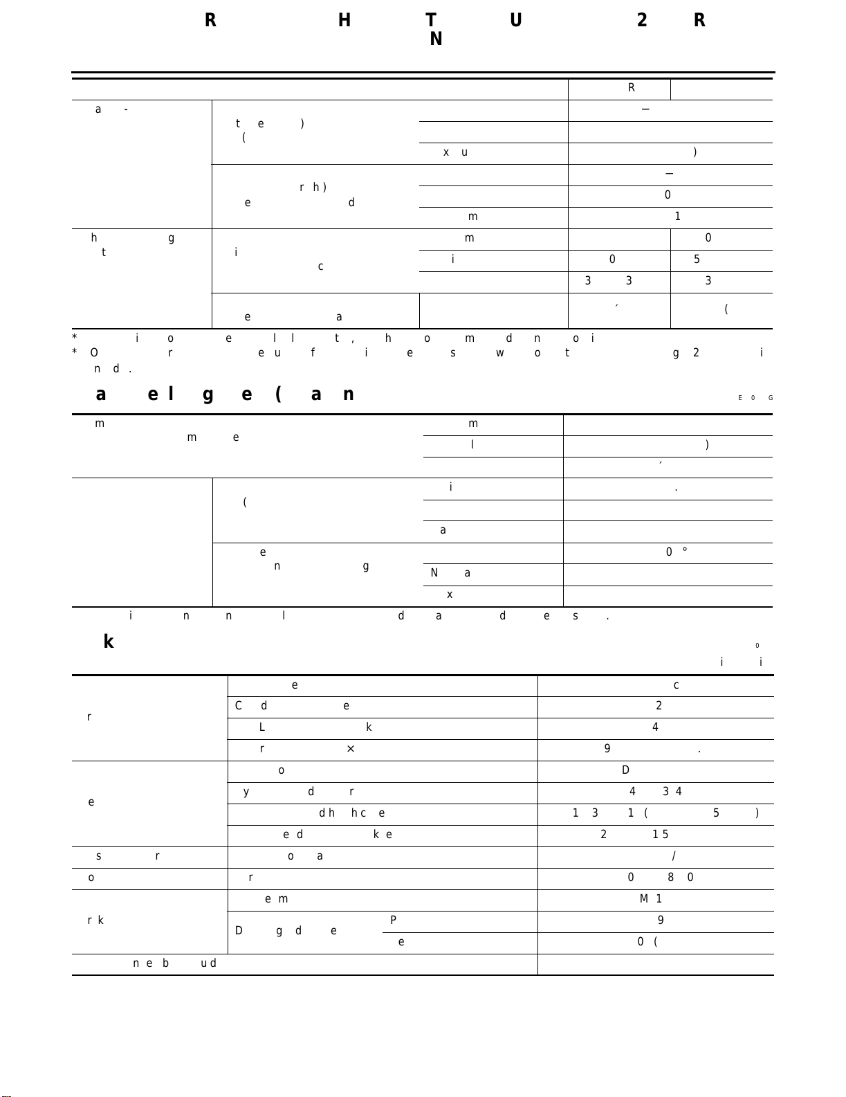
QUICK REFERENCE CHART: ALTIMA (EQUIPPED WITH 2.5L QR
ENGINE)
2002
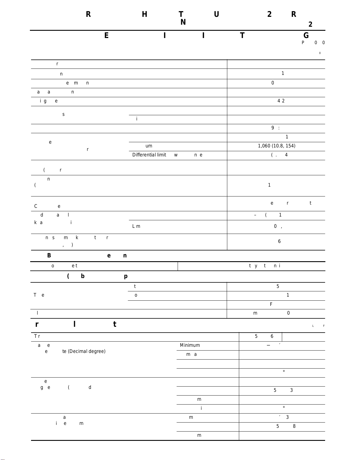
QUICK REFERENCE CHART: ALTIMA (EQUIPPED WITH 2.5L QR ENGINE)
PFP:00000
Engine Tune-Up Data ELS000ME
Cylinder arrangement In-line 4
3
Displacement cm
Bore and stroke mm (in) 89.0 x 100 (3.50 - 3.94)
Valve arrangement DOHC
Firing order 1-3-4-2
Number of piston rings
Compression ratio 9.5:1
Compression pressure
kPa (kg/cm
Idle speed rpm
A/T (in neutral)
Ignition timing
(BTDC at idle speed) 15° ± 5°
2
,
(cu in)
psi) / 250 rpm
Compression 2
Oil 1
Standard 1,250 (12.8, 182)
Minimum 1,060 (10.8, 154)
Differential limit between cylinders 98 (1.0, 14)
2,488 (151.82)
700 ± 50
CO% at idle
Radiator cap relief pressure
kPa (kg/cm
Cooling system leakage testing pressure
kPa (kg/cm2 ,
2
,
psi)
psi)
Standard 79 – 98 (0.8 – 1.0, 11 – 14)
Limit 59 (0.6, 9)
0.3 – 9.5% and engine runs smoothly
157 (1.6, 23)
Drive Belt Deflection and Tension
Tension of drive belts
Auto adjustment by auto-tensioner
Spark Plugs (Double Platinum Tipped)
Standard PLFR5A-11
Type
Plug gap Nominal: 1.1 mm (0.043 in)
Hot PLFR4A-11
Cold PLFR6A-11
Front Wheel Alignment (Unladen*1) ELS000MF
Tire size 205/65R16 215/55R17
Camber
Degree minute (Decimal degree)
Caster
Degree minute (Decimal degree)
Kingpin inclination
Degree minute (Decimal degree)
Minimum −1°00′ (−1.00°)
Nominal −0°15′ (−0.25°)
Maximum 0°30′ (0.50°)
Left and right difference 45′ (0.75°) or less
Minimum 2°05′ (2.08°)
Nominal 2°50′ (2.83°)
Maximum 3°35′ (3.58°)
Left and right difference 45′ (0.75°) or less
Minimum 13°50′ (13.83°)
Nominal 14°35′ (14.58°)
Maximum 15°20′ (15.33°)
Page 5
QUICK REFERENCE CHART: ALTIMA (EQUIPPED WITH 2.5L QR
ENGINE)
2002
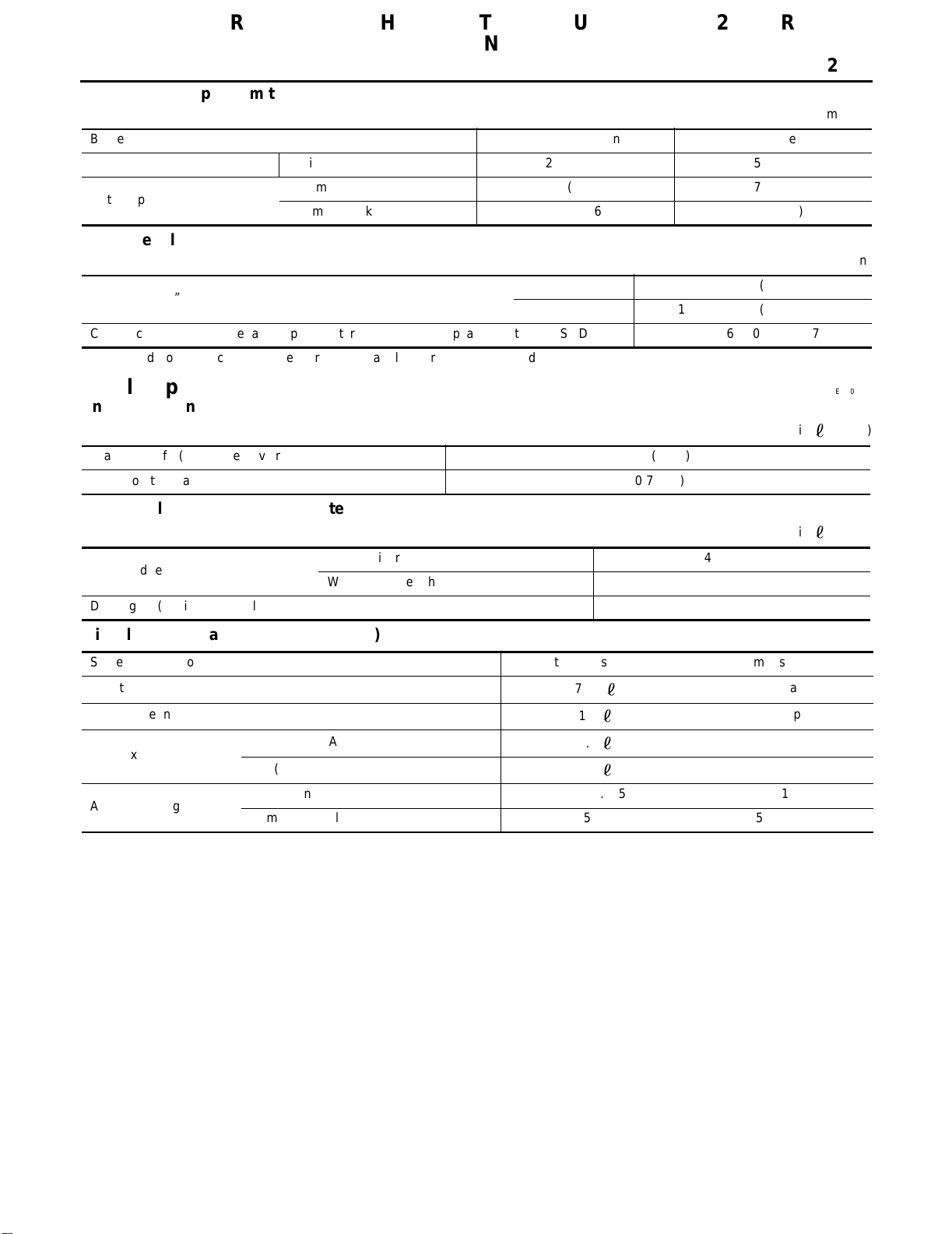
Tire size 205/65R16 215/55R17
Tota l toe-in
Distance (A − B)
mm (in)
Angle (left plus right)
Degree minute (Decimal degree)
Wheel turning angle
Full turn*2
*1: Fuel, radiator coolant and engine oil full. Spare tire, jack, hand tools and mats in designated positions.
*2: On power steering models, wheel turning force (at circumference of steering wheel) of 98 to 147 N (10 to 15 kg, 22 to 33 lb) with
engine idle.
Inside
Degree minute (Decimal degree)
Outside
Degree minute (Decimal degree)
Minimum −0.5 (−0.02)
Nominal 0.5 (0.02)
Maximum 1.5 (0.06)
Minimum −4′ (−0.07°)
Nominal 2′ (0.03°)
Maximum 8′ (0.13°)
Minimum 34°30′ (34.5°)32°00′ (32.0°)
Nominal 38°00′ (38.0°)35°30′ (35.5°)
Maximum 39°00′ (39.0°)36°30′ (36.5°)
Nominal 30°30′ (30.5°)29°00′ (29.0°)
Rear Wheel Alignment (Unladen*) ELS000MG
Camber
Degree minute (Decimal degree)
Tota l toe-in Distance (A − B)
mm (in)
Angle (left plus right)
Degree minute (Decimal degree)
*: Fuel, radiator coolant and engine oil full. Spare tire, jack, hand tools and mats in designated positions.
Minimum −0°04′ (−0.07°)
Nominal −0°34′ (−0.57°)
Maximum 0°64′ (-1.07°)
Minimum 2.4 (0.09)
Nominal 3.9 (0.15)
Maximum 5.4 (0.21)
Minimum 6′ (0.1°)
Nominal 10′ (0.167°)
Maximum 14′ (0.233°)
Brake ELS000MH
Unit: mm (in)
Brake model CLZ25VD disc brake
Front brake
Rear brake
Master cylinder Cylinder bore diameter 23.81 (15/16)
Control valve Screw in type 30 × 0.4 (1.18 × 0.02)
Brake booster
Recommended brake fluid DOT 3
Cylinder bore diameter 57.2 (2.252)
Pad Length × width × thickness 125.6 × 46 × 11 (4.94 × 1.81 × 0.43)
Rotor outer diameter × thickness 296 × 26 (11.65 × 1.02)
Brake model AD9V disc brake
Cylinder bore diameter 34.9 (1.3740)
Pad Length × width × thickness 89.1 × 39.5 × 10 (3.508 × 1.555 × 0.31)
Rotor outer diameter × thickness 292 × 9 (11.50 × 0.35)
Booster model M215T
Diaphragm diameter
Primary 230 (9.06)
Secondary 205 (8.07)
Page 6
QUICK REFERENCE CHART: ALTIMA (EQUIPPED WITH 2.5L QR
ENGINE)
2002
Disc Brake - Repair Limits
Unit: mm (in)
Brake model CLZ25VD (Front) AD9V (Rear)
Pad wear limit Minimum thickness 2.0 (0.079) 1.5 (0.059)
Rotor repair limit
Brake Pedal
Free height “H”*
Clearance “C” between pedal stopper and threaded end of stop lamp switch or ASCD switch 0.74 - 1.96 (0.0291 - 0.0772)
*: Measured from surface of dash reinforcement panel to surface of pedal pad
Maximum runout 0.07 (0.0028) 0.07 (0.0028)
Minimum thickness 22.0 (0.866) 8.0 (0.31)
Unit: mm (in)
M/T 164.1 - 174.1 (6.46 - 6.85)
A/T 173.1 - 183.1 (6.81 - 7.21)
Refill Capacities ELS000MI
Engine Coolant Capacity (Approximate)
Unit:
(US qt)
Drain and refill (without reservoir) 6.9 (7 1/4)
Reservoir tank (at MAX level) 0.7 (3/4)
Engine Oil Capacity (Approximate)
Unit:
Drain and refill
Dry engine (engine overhaul) 4.6 (4 7/8)
With oil filter change 4.2 (4 1/2)
Without oil filter change 4.0 (4 1/4)
Miscellaneous Capacity (Approximate)
System description Metric measurement US measurement
Fuel tank
Power steering system
Transaxle
Air conditioning system
75.5
1.0
M/T (RS5F51A)
A/T (RE4F04B)
Refrigerant 0.475 - 0.525 kg 1.045 - 1.155 lb
Compressor oil 150 ml 5.03 fl oz
2.3
9.2
20 gal
2 1/8 pt
2 3/8 qt
9 3/4 qt
(US qt)
Page 7
QUICK REFERENCE CHART: ALTIMA (EQUIPPED WITH 3.5L, VQ
ENGINE)
2002
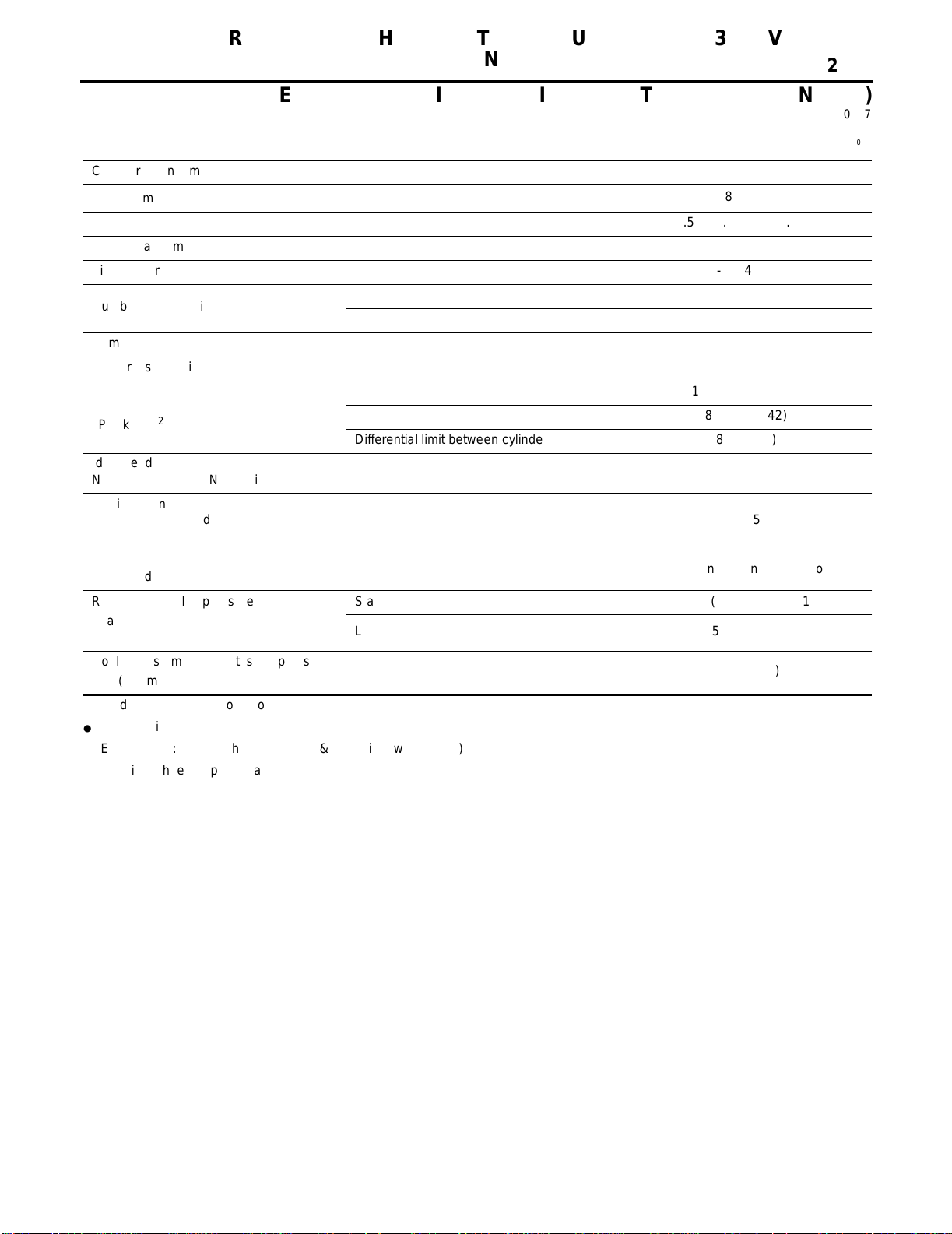
QUICK REFERENCE CHART: AL TIMA (EQUIPPED WITH 3.5L, VQ ENGINE)
PFP:00027
Engine Tune-Up Data ELS000MJ
Cylinder arrangement V-6
Displacement cm
Bore and stroke mm (in) 95.5 x 81.4 (3.76 - 3.205)
Valve arrangement DOHC
Firing order 1-2-3-4-5-6
Number of piston rings
Number of main bearings 4
Compression ratio 10.0:1
Compression pressure
kPa (kg/cm
Idle speed rpm
No-load*1 (in “P” or N” position)
Ignition timing
(BTDC at idle speed) 15° ± 5°
3
2
,
psi) / 250 rpm
(cu in)
Compression 2
Oil 1
Standard 1,275 (13.0, 185)
Minimum 981 (10.0, 142)
Differential limit between cylinders 98 (1.0, 14)
3,498 (213.45)
700 ± 50
CO% at idle
Radiator cap relief pressure
kPa (kg/cm
Cooling system leakage testing pressure
kPa (kg/cm2 ,
*1: Under the following conditions:
● Air
● Electric
● Steering
2
,
psi)
psi)
conditioner switch: OFF
load: OFF (Lights, heater fan & rear window defogger)
wheel: Kept in straight-ahead position
0.7 – 9.9% and engine runs smoothly
Standard 79 – 98 (0.8 – 1.0, 11 – 14)
Limit 59 (0.6, 9)
157 (1.6, 23)
Page 8
QUICK REFERENCE CHART: ALTIMA (EQUIPPED WITH 3.5L, VQ
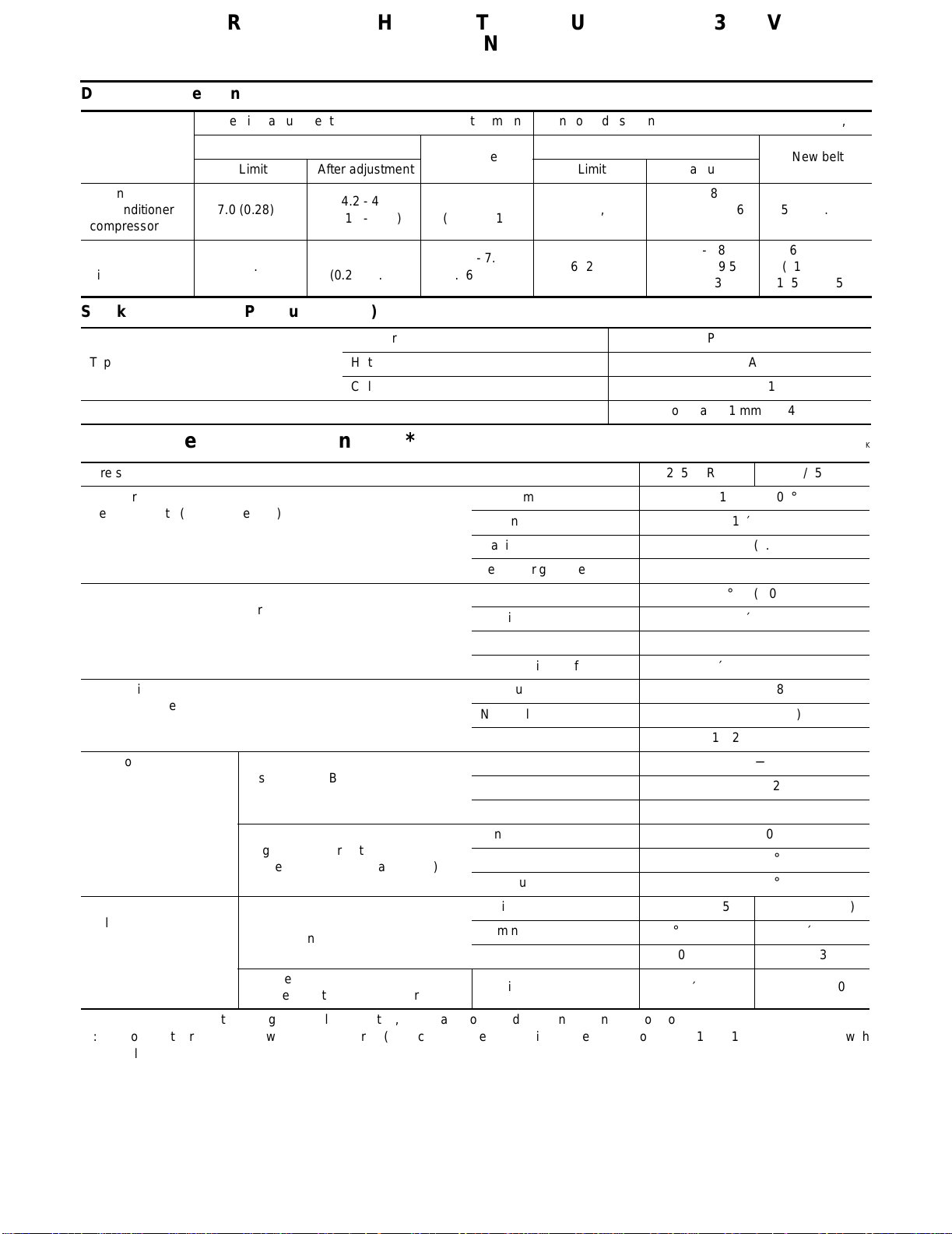
Drive Belt Deflection and Tension
ENGINE)
2002
Alternator,
Air conditioner
compressor
Power steering
oil pump
Deflection adjustment
Limit After adjustment Limit
7.0 (0.28)
11.0 (0.43)
Used belt
4.2 - 4.6
(0.17 - 0.18)
7.3 - 8.0
(0.29 - 0.32)
Unit: mm (in) Tension adjustment
New belt
3.7 - 4.1
(0.15 - 0.16)
6.5 - 7.2
(0.26 - 0.28)
294 (30, 66)
196 (20, 44)
Used belt
After adjustment
730 - 818
(74.5 - 83.5, 164
- 184)
495 - 583
(50.5 - 59.5,
111.3 - 131.1)
Unit: N (kg, lb)
New belt
838 - 926
(85.5 - 94.5, 188
- 208)
603 - 691
(61.5 - 70.5,
135.6 - 155.4)
Spark Plugs (Double Platinum Tipped)
Standard PLFR5A-11
Type
Plug gap Nominal: 1.1 mm (0.043 in)
Hot PLFR4A-11
Cold PLFR6A-11
Front Wheel Alignment (Unladen*1) ELS000MK
Tire size 205/65R16 215/55R17
Camber
Degree minute (Decimal degree)
Caster
Degree minute (Decimal degree)
Kingpin inclination
Degree minute (Decimal degree)
Tota l toe-in
Distance (A − B)
mm (in)
Angle (left plus right)
Degree minute (Decimal degree)
Wheel turning angle
Full turn*2
*1: Fuel, radiator coolant and engine oil full. Spare tire, jack, hand tools and mats in designated positions.
*2: On power steering models, wheel turning force (at circumference of steering wheel) of 98 to 147 N (10 to 15 kg, 22 to 33 lb) with
engine idle.
Inside
Degree minute (Decimal degree)
Outside
Degree minute (Decimal degree)
Minimum −1°00′ (−1.00°)
Nominal −0°15′ (−0.25°)
Maximum 0°30′ (0.50°)
Left and right difference 45′ (0.75°) or less
Minimum 2°05′ (2.08°)
Nominal 2°50′ (2.83°)
Maximum 3°35′ (3.58°)
Left and right difference 45′ (0.75°) or less
Minimum 13°50′ (13.83°)
Nominal 14°35′ (14.58°)
Maximum 15°20′ (15.33°)
Minimum −0.5 (−0.02)
Nominal 0.5 (0.02)
Maximum 1.5 (0.06)
Minimum −4′ (−0.07°)
Nominal 2′ (0.03°)
Maximum 8′ (0.13°)
Minimum 34°30′ (34.5°)32°00′ (32.0°)
Nominal 38°00′ (38.0°)35°30′ (35.5°)
Maximum 39°00′ (39.0°)36°30′ (36.5°)
Nominal 30°30′ (30.5°)29°00′ (29.0°)
Page 9
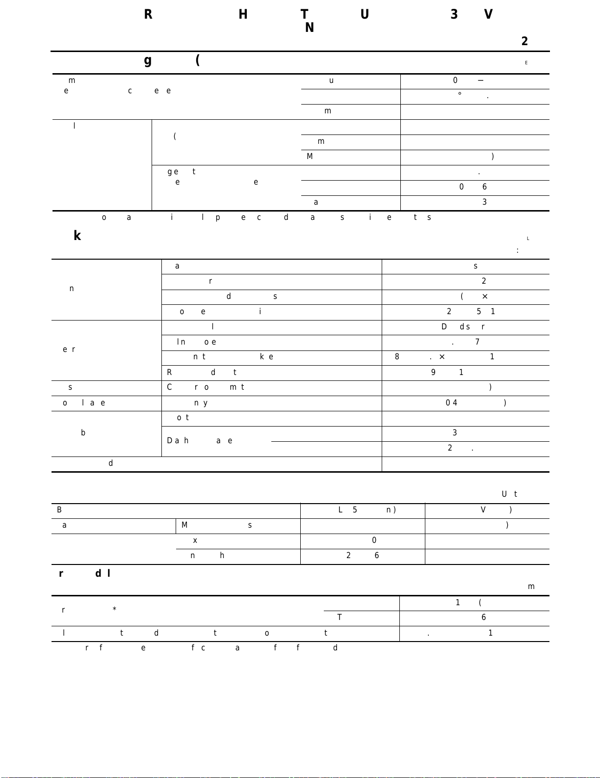
QUICK REFERENCE CHART: ALTIMA (EQUIPPED WITH 3.5L, VQ
ENGINE)
2002
Rear Wheel Alignment (Unladen*) ELS000ML
Camber
Degree minute (Decimal degree)
Total toe-in Distance (A − B)
mm (in)
Angle (left plus right)
Degree minute (Decimal degree)
*: Fuel, radiator coolant and engine oil full. Spare tire, jack, hand tools and mats in designated positions.
Minimum −0°10′ (−0.17°)
Nominal −0°40′ (−0.67°)
Maximum -0°70′ (-1.17°)
Minimum 2.5 (0.10)
Nominal 4.0 (0.16)
Maximum 5.5 (0.22)
Minimum 6′ (0.1°)
Nominal 10′ (0.167°)
Maximum 14′ (0.233°)
Brake ELS000MM
Unit: mm (in)
Brake model CLZ25VD disc brake
Front brake
Rear brake
Master cylinder Cylinder bore diameter 23.81 (15/16)
Control valve Screw in type 30 × 0.4 (1.18 × 0.02)
Brake booster
Recommended brake fluid DOT 3
Cylinder bore diameter 57.2 (2.252)
Pad Length × width × thickness 125.6 × 46 × 11 (4.94 × 1.81 × 0.43)
Rotor outer diameter × thickness 296 × 26 (11.65 × 1.02)
Brake model AD9V disc brake
Cylinder bore diameter 34.9 (1.3740)
Pad Length × width × thickness 89.1 × 39.5 × 10 (3.508 × 1.555 × 0.31)
Rotor outer diameter × thickness 292 × 9 (11.50 × 0.35)
Booster model M215T
Diaphragm diameter
Primary 230 (9.06)
Secondary 205 (8.07)
Disc Brake - Repair Limits
Unit: mm (in)
Brake model CLZ25VD (Front) AD9V (Rear)
Pad wear limit Minimum thickness 2.0 (0.079) 1.5 (0.059)
Rotor repair limit
Maximum runout 0.07 (0.0028) 0.07 (0.0028)
Minimum thickness 22.0 (0.866) 8.0 (0.31)
Brake Pedal
Unit: mm (in)
Free height “H”*
Clearance “C” between pedal stopper and threaded end of stop lamp switch or ASCD switch 0.74 - 1.96 (0.0291 - 0.0772)
*: Measured from surface of dash reinforcement panel to surface of pedal pad
M/T 164.1 - 174.1 (6.46 - 6.85)
A/T 173.1 - 183.1 (6.81 - 7.21)
Page 10
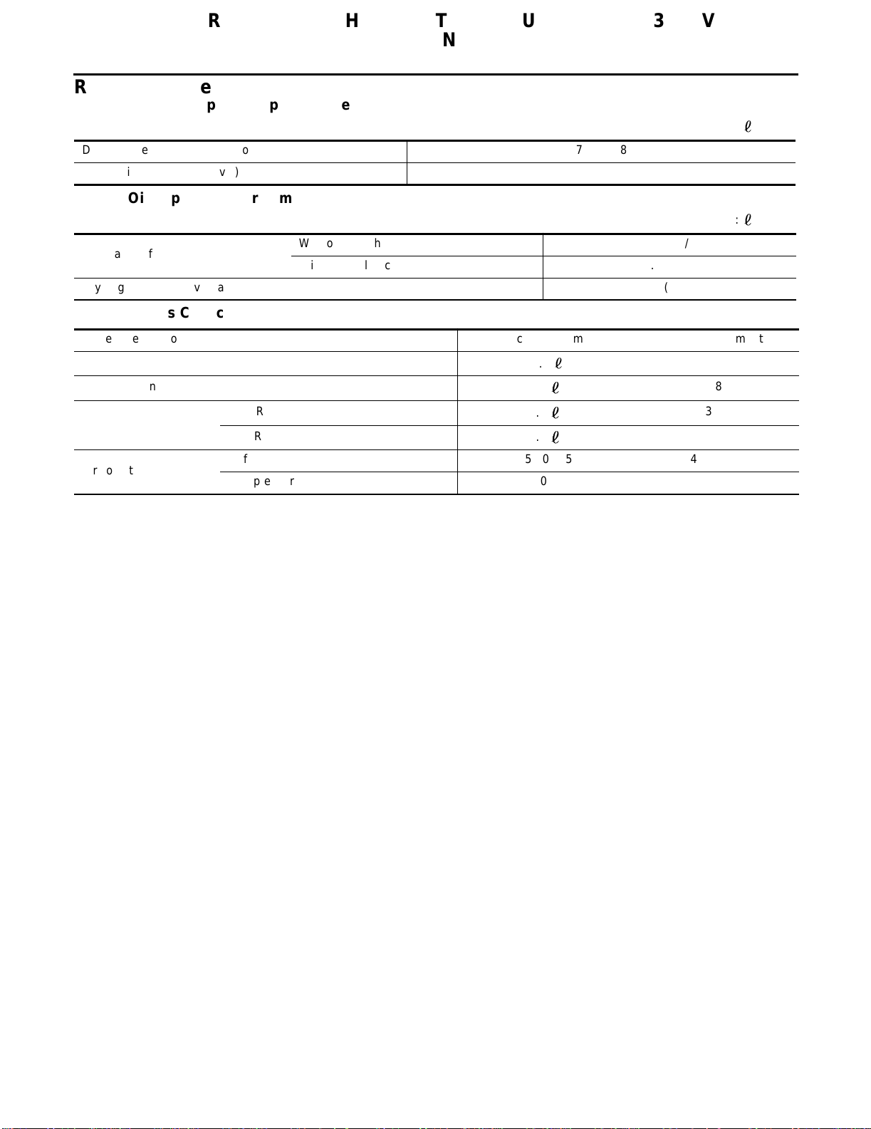
QUICK REFERENCE CHART: ALTIMA (EQUIPPED WITH 3.5L, VQ
ENGINE)
2002
Refill Capacities
Engine Coolant Capacity (Approximate)
Unit:
Drain and refill (without reservoir) 7.5 (7 7/8)
Reservoir tank (at MAX level) 0.7 (3/4)
Engine Oil Capacity (Approximate)
Unit:
Drain and refill
Dry engine (engine overhaul) 5.0 (5 1/4)
Miscellaneous Capacity (Approximate)
System description Metric measurement US measurement
Fuel tank
Power steering system
Transaxle
Air conditioning system
M/T (RS5F51A)
A/T (RE4F04B)
Refrigerant 0.475 - 0.525 kg 1.045 - 1.155 lb
Compressor oil 150 ml 5.03 fl oz
With oil filter change 4.0 (4 1/4)
Without oil filter change 3.7 (3 7/8)
75.5
1.0
2.3
9.2
20 gal
2 1/8 pt
2 3/8 qt
9 3/4 qt
(US qt)
(US qt)
ELS000MN
Page 11
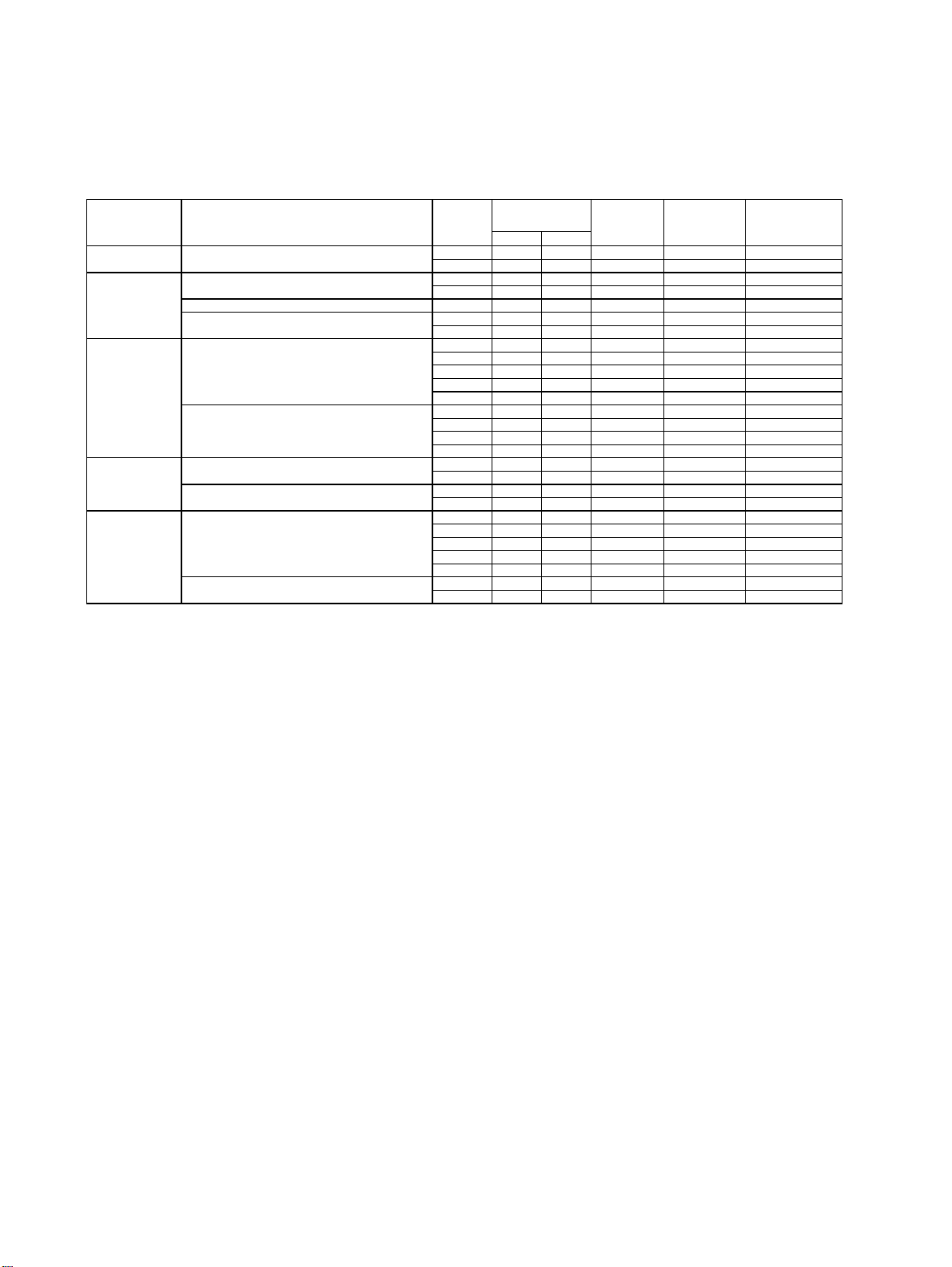
Attachment No.18
QR25DE
TEST VALUE AND TEST LIMIT (GST ONLY — NOT APPLICABLE TO CONSULT-II)
The following is the information specified in Mode 6 of SAE J1979.
The test value is a parameter used to determine whether a system/circuit diagnostic test is “OK” or “NG” while
being monitored by the ECM during self-diagnosis. The test limit is a reference value which is specified as the
maximum or minimum value and is compared with the test value being monitored.
Items for which these data (test value and test limit) are displayed are the same as SRT code items.
These data (test value and test limit) are specified by Test ID (TID) and Component ID (CID) and can be displayed on the GST screen.
SRT item Self-diagnostic test item DTC
CATALYST Three way catalyst function (Bank 1)
EVAP control system (Small leak)
EVAP SYSTEM
HO2S
HO2S HTR
EGR SYSTEM
★
1:Except models L31 QR25DE engine 2002MY and L31 QR25DE engine 2003MY.
EVAP control system purge flow monitoring P0441 06H 83H Min. X mV
EVAP control system (Very small leak)
Heated oxygen sensor 1
Heated oxygen sensor 2
Heated oxygen sensor 1 heater
Heated oxygen sensor 2 heater
★
1
EGR function
EGRC-BPT valve function
P0420 01H 01H Max. X P0420 02H 81H Min. X P0442 05H 03H Max. X P1442 05H 03H Max. X -
P0456 07H 03H Max. X P1456 07H 03H Max. X P0133 09H 04H Max. X ms
P1143 0AH 84H Min. X mV
P1144 0BH 04H Max. X mV
P0132 0CH 04H Max. X mV
P0134 0DH 04H Max. X s
P0139 19H 86H Min. X mV/500ms
P1147 1AH 86H Min. X mV
P1146 1BH 06H Max. X mV
P0138 1CH 06H Max. X mV
P0032 29H 08H Max. X mV
P0031 2AH 88H Min. X mV
P0038 2DH 0AH Max. X mV
P0037 2EH 8AH Min. X mV
P0400 31H 8CH Min. X ℃
P0400 32H 8CH Min. X ℃
P0400 33H 8CH Min. X ℃
P0400 34H 8CH Min. X ℃
P1402 35H 0CH Max. X ℃
P0402 36H 0CH Max. X P0402 37H 8CH Min. X -
Test value
(GST display)
TID CID
Te s t limit Application Unit
Applicable ・: Not applicable
Page 12

Attachment No.19
0
VQ35DE
TEST VALUE AND TEST LIMIT (GST ONLY — NOT APPLICABLE TO CONSULT-II)
The following is the information specified in Mode 6 of SAE J1979.
The test value is a parameter used to determine whether a system/circuit diagnostic test is “OK” or “NG” while
being monitored by the ECM during self-diagnosis. The test limit is a reference value which is specified as the
maximum or minimum value and is compared with the test value being monitored.
Items for which these data (test value and test limit) are displayed are the same as SRT code items.
These data (test value and test limit) are specified by Test ID (TID) and Component ID (CID) and can be displayed on the GST screen.
SRT item Self-diagnostic test item DTC
CATALYST
EVAP SYSTEM
HO2S
HO2S HTR
EGR SYSTEM
★
1:Except models L31 VQ35DE engine, F50 VK45DE engine, Y34 VK45DE engine 2
Three way catalyst function (Bank 1)
Three way catalyst function (Bank 2)
EVAP control system (Small leak)
EVAP control system purge flow monitoring P0441 06H 83H Min. X mV
EVAP control system (Very small leak)
Heated oxygen sensor 1(Bank 1)
Heated oxygen sensor 1(Bank 2)
Heated oxygen sensor 2(Bank 1)
Heated oxygen sensor 2(Bank 2)
Heated oxygen sensor 1 heater(Bank 1)
Heated oxygen sensor 2 heater(Bank 2)
Heated oxygen sensor 2 heater(Bank 1)
Heated oxygen sensor 2 heater(Bank 2)
★
1
EGR function
EGRC-BPT valve function
P0420 01H 01H Max. X P0420 02H 81H Min. X P0430 03H 02H Max. X P0430 04H 82H Min. X P0442 05H 03H Max. X P1442 05H 03H Max. X -
P0456 07H 03H Max. X P1456 07H 03H Max. X P0133 09H 04H Max. X ms
P1143 0AH 84H Min. X mV
P1144 0BH 04H Max. X mV
P0132 0CH 04H Max. X mV
P0134 0DH 04H Max. X s
P0153 11H 05H Max. X ms
P1163 12H 85H Min. X mV
P1164 13H 05H Max. X mV
P0152 14H 05H Max. X mV
P0154 15H 05H Max. X s
P0139 19H 86H Min. X mV/500ms
P1147 1AH 86H Min. X mV
P1146 1BH 06H Max. X mV
P0138 1CH 06H Max. X mV
P0159 21H 87H Min. X mV/500ms
P1167 22H 87H Min. X mV
P1166 23H 07H Max. X mV
P0158 24H 07H Max. X mV
P0032 29H 08H Max. X mV
P0031 2AH 88H Min. X mV
P0052 2BH 09H Max. X mV
P0051 2CH 89H Min. X mV
P0038 2DH 0AH Max. X mV
P0037 2EH 8AH Min. X mV
P0058 2FH 0BH Max. X mV
P0057 30H 8BH Min. X mV
P0400 31H 8CH Min. X ℃
P0400 32H 8CH Min. X ℃
P0400 33H 8CH Min. X ℃
P0400 34H 8CH Min. X ℃
P1402 35H 0CH Max. X ℃
P0402 36H 0CH Max. X P0402 37H 8CH Min. X -
Test value
(GST display)
TID CID
Te s t limit Application Unit
Applicable ・: Not applicable
Page 13

B ENGINE
A
ACC
SECTION ACC
ACCELERA T OR CONTROL SYSTEM
CONTENTS
ACCELERATOR CONTROL SYSTEM ...................... 2
Removal and Installation .......................................... 2
SERVICE DATA AND SPECIFICATIONS (SDS) ........4
Accelerator Control ...................................................4
PEDAL TRAVEL ....................................................4
C
D
E
F
G
H
I
J
M
K
L
ACC-1
Page 14
ACCELERATOR CONTROL SYSTEM
ACCEL ER ATOR CONTROL SYSTEM
PFP:18005
Removal and Installation EBS008QZ
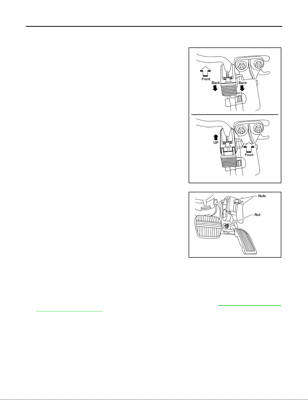
1. Disconnect the accelerator position sensor electrical connector.
a. Pull the connector lock back to unlock the connecto r from the
accelerator pedal position sensor as shown.
b. Pull up o n the connector to disconnect it from the accelerator
pedal position sensor as shown.
LBIA0075E
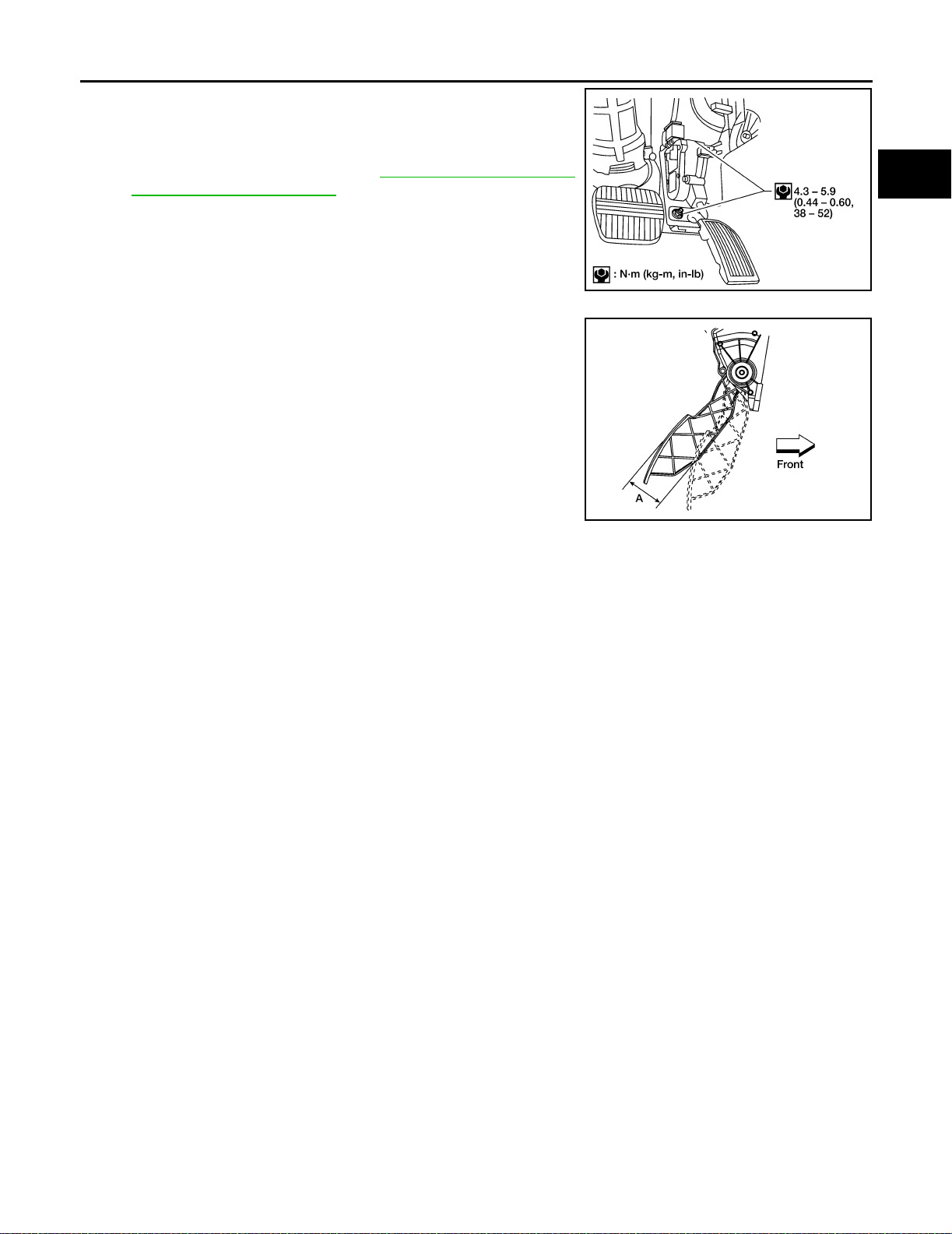
2. Remov e the upper and lower accelerator pedal nuts.
LBIA0060E
3. Remov e the accelerator pedal and accelerator position sensor assembly.
a. Do not disass emble the pedal assembly. Do not remove the accele rator pedal position sensor from the
pedal assembly.
b. Avoid impact from dropping during handling.
c. Keep the pedal assembly away from water.
d. For electrical inspection of the accelerator pedal position sensor. Refer to EC-49, "
Accelerator Pedal
Released Position Learning" .
ACC-2
Page 15
ACCELERATOR CONTROL SYSTE M
4. Installation should be performed in the reverse procedure of
removal.
● When the harness connector of the accelerator peda l position
sensor is disconnected , perform the "Accelerator pedal position released learning". Refer to EC-49, "
Released Position Learning" .
● Check the accelerator pedal for smooth operation. There
should be no binding or sticking wh en applying or releasing
the accelerator pedal.
● Check that the accelerator pedal mov e s through the full spec-
ified distance of pedal travel.
Pedal travel A: 52.6 - 58.2 mm (2.07 - 2.29 in)
Accelerator Pedal
A
ACC
C
LBIA0061E
D
E
F
G
LBIA0062E
M
H
I
J
K
L
ACC-3
Page 16

SERVICE DATA AND SPECIFICATIONS (SDS)
SERVICE DATA AND SP ECIFICATIONS (SDS)
PFP:00030
Accelerator Control EBS008R0
PEDAL TRAVEL
Accelerator control pedal - total travel 52.6 - 58.2 mm (2.07 - 2.29 in)
ACC-4
Page 17

K ELECTRICAL
A
B
SECTION ACS
AUTO CRUISE CONTROL SYSTEM
CONTENTS
AUTOMATIC SPEED CONTROL DEVICE (ASCD) ..... 2
Description ............................................................... 2
C
D
E
F
G
H
I
J
ACS
L
M
ACS-1
Page 18

AUTOMATI C SPEED CONTROL DEVIC E (ASCD)
AUTOMATIC SPEED CONTROL DEVICE (ASC D)
PFP:18930
Description EKS002L4
Regarding the information for ASCD system, refer to EC-628, "AUTOMATIC SPEED CONTROL DEVICE
(ASCD)" (QR engine models), EC -1286, "AUTOMATIC SPEED CONTROL DEVICE (ASCD)" (VQ en gine
models).
ACS-2
Page 19

C TRANSMISSION/TRANSAXLE
A
B
SECTION AT
CONTENTS
TROUBLE DIAGNOSIS - INDEX ................................ 5
Alphabetical & P No. Index for DTC . ........................ 5
PRECAUTIONS .......................................................... 7
Precautions for Supplemental Restraint System
(SRS) “AIR BAG” and “SEAT BELT PRE-TEN-
SIONER” ..................................................................7
Precautions for On Board Diagnostic (OBD) System
of A/T and Engine .................................................... 7
Precautions .............................................................. 7
Service Noti ce or Pre ca u ti o ns ........... .............. ......... 9
Wiring Diagrams and Trouble Diagnosis ................ 10
PREPARATION ..........................................................11
Special Service Tools .............................................. 11
Commercial Service Tools ...................................... 14
OVERALL SYSTEM ................................................. 15
A/T Electrical Parts Location .................................. 15
Circuit Diagra m ........... ........................................... 16
Cross-secti o n al View .............................................. 17
Hydraulic Control Circuit ........................................ 18
Shift Mechanism ..................................................... 19
Control System ....................................................... 28
Control Mechanism ................................................ 30
Control Va lve .......................................................... 34
ON BOARD DIAGNOSTIC SYSTEM DESCRIP-
TION .......................................................................... 36
Introduction ............................................................ 36
OBD-II Function for A/T System ............................. 36
One or Two Trip Detection Logic of OBD-II ............ 36
OBD-II Diagnostic Trouble Code (DTC) ................. 36
Malfunction Indicator Lamp ( MIL) ........................... 40
CONSULT-II ........................................................... 40
Diagnostic Procedure Without CONSULT-II ........... 50
TROUBLE DIAGNOSIS - INTRODUCTION ............. 55
Introduction ............................................................ 55
Work Flow .............................................................. 59
TROUBLE DIAGNOSIS - BASIC INSPECTION ...... 61
A/T Fluid Check ...................................................... 61
Stall Test ................................................................. 61
Line Pressure Test ........... .............. ........................ 65
Road Test ............................................................... 66
AUTOMATIC TRANSAXLE
TROUBLE DIAGNOSIS - GENERAL DESCRIP-
TION .......................................................................... 82
Symptom Chart .......................................................82
TCM Terminal s and Reference Value .. ................... 92
CAN Communication .............................................. 95
TROUBLE DIAGNOSIS FOR POWER SUPPLY ....100
Wiring Diagra m — AT — MAIN ............................100
Diagnostic Procedure ...........................................101
DTC P0705 PARK/NEUTRAL POSITION SWITCH .103
Description ............................................................103
On Board Diagnosis Logic ....................................103
Possible Cause .....................................................103
Diagnostic Trouble Code (DTC) Confirmation Pro-
cedure ...................................................................103
Wiring Diagra m — AT — PNP/SW .......................105
Diagnostic Procedure ...........................................106
DTC P0710 A/T FLUID TEMPERAT URE SENSOR
CIRCUIT ..................................................................109
Description ............................................................109
On Board Diagnosis Logic ....................................109
Possible Cause .....................................................109
Diagnostic Trouble Code (DTC) Confirmation Pro-
cedure ...................................................................109
Wiring Diagra m — AT — FTS ...............................111
Diagnostic Procedure ...........................................113
DTC P0720 VE HICLE SPEED SEN SOR·A/ T (REV -
OLUTION SENSOR) ...............................................115
Description ............................................................115
On Board Diagnosis Logic ....................................115
Possible Cause .....................................................115
Diagnostic Trouble Code (DTC) Confirmation Pro-
cedure ...................................................................115
Wiring Diagram — AT — VSSA/T ........................117
Diagnostic Procedure ...........................................118
DTC P0725 ENGINE SPEED SIGNAL ............ .......120
Description ............................................................120
On Board Diagnosis Logic ....................................120
Possible Cause .....................................................120
Diagnostic Trouble Code (DTC) Confirmation Pro-
cedure ...................................................................120
AT
D
E
F
G
H
I
J
K
L
M
AT-1
Page 20

Wiring Dia gram — AT — ENGSS .........................121
Diagnostic Procedure ...........................................122
DTC P0731 A/T 1ST GEAR FUNCTION .................124
Description ............................................................124
On Board Diagnosis Logic ....................................124
Possible Cause .................................... .................124
Diagnostic Trouble Code (DTC) Confirmation Pro-
cedure ...................................................................124
Wiring Dia gram — AT — 1ST ...............................126
Diagnostic Procedure ...........................................127
DTC P0732 A/T 2ND GEAR FUNCTION ................129
Description ............................................................129
On Board Diagnosis Logic ....................................129
Possible Cause .................................... .................129
Diagnostic Trouble Code (DTC) Confirmation Pro-
cedure ...................................................................129
Wiring Dia gram — AT — 2ND ..............................131
Diagnostic Procedure ...........................................132
DTC P0733 A/T 3RD GEAR FUNCTION ................134
Description ............................................................134
On Board Diagnosis Logic ....................................134
Possible Cause .................................... .................134
Diagnostic Trouble Code (DTC) Confirmation Pro-
cedure ...................................................................134
Wiring Dia gram — AT — 3RD ..............................136
Diagnostic Procedure ...........................................137
DTC P0734 A/T 4TH GEAR FUNCTION ................139
Description ............................................................139
On Board Diagnosis Logic ....................................139
Possible Cause .................................... .................139
Diagnostic Trouble Code (DTC) Confirmation Pro-
cedure ...................................................................139
Wiring Dia gram — AT — 4TH ...............................141
Diagnostic Procedure ...........................................142
DTC P0740 TORQUE CONVERTER CLUTCH
SOLENOID VALVE ...... .............. .............................146
Description ............................................................146
On Board Diagnosis Logic ....................................146
Possible Cause .................................... .................146
Diagnostic Trouble Code (DTC) Confirmation Pro-
cedure ...................................................................146
Wiring Dia gram — AT — TCV ..............................148
Diagnostic Procedure ...........................................149
DTC P0744 A/T TCC S/V FUNCTION (LOCK-UP) .151
Description ............................................................151
On Board Diagnosis Logic ....................................151
Possible Cause .................................... .................151
Diagnostic Trouble Code (DTC) Confirmation Pro-
cedure ...................................................................151
Wiring Dia gram — AT — TCCSIG ........................153
Diagnostic Procedure ...........................................154
DTC P0745 LINE PRESSURE SOLENOID V ALVE .159
Description ............................................................159
On Board Diagnosis Logic ....................................159
Possible Cause .................................... .................159
Diagnostic Trouble Code (DTC) Confirmation Pro-
cedure ...................................................................159
Wiring Diagram — AT — LPSV ............................161
Diagnostic Procedure ...........................................162
DTC P0750 SHIFT SOLENOID VA LVE A ...............165
Description ............................................................165
On Board Diagnosis Logi c ..... ...............................165
Possible Cause .....................................................165
Diagnostic Trouble Code (DTC) Confirmation Pro-
cedure ...................................................................165
Wiring Diagram — AT — SSV/A ...........................167
Diagnostic Procedure ............................................168
DTC P0755 SHIFT SOLENOID VA LVE B ...............170
Description ............................................................170
On Board Diagnosis Logi c ..... ...............................170
Possible Cause .....................................................170
Diagnostic Trouble Code (DTC) Confirmation Pro-
cedure ...................................................................170
Wiring Diagram — AT — SSV/B ...........................172
Diagnostic Procedure ............................................173
DTC P1705 THROTTLE POSITION SENSOR
[ACCELERATOR PEDAL POSITION (APP) SEN-
SOR] ........................................................................175
Description ............................................................175
On Board Diagnosis Logi c ..... ...............................175
Possible Cause .....................................................175
Diagnostic Trouble Code (DTC) Confirmation Pro-
cedure ...................................................................175
Wiring Diagram — AT — TPS ...............................177
Diagnostic Procedure ............................................178
DTC P1760 OVERRUN CLUTCH SOLENOID
VALVE ......................................................................180
Description ............................................................180
On Board Diagnosis Logi c ..... ...............................180
Possible Cause .....................................................180
Diagnostic Trouble Code (DTC) Confirmation Pro-
cedure ...................................................................180
Wiring Diagram — AT — OVRCSV ......................182
Diagnostic Procedure ............................................183
DTC U1000 CAN COMMUNICAT ION LINE ............185
Description ............................................................185
On Board Diagnosis Logi c ..... ...............................185
Possible Cause .....................................................185
DTC Confirmation Procedure ........ ........................185
Wiring Diagram — AT — CAN ..............................187
Diagnostic Procedure ............................................188
DTC BATT/FLUID TE MP S EN ( A /T FLU I D TE M P
SENSOR CIRCUIT AND TCM POWER SOURCE) .189
Description ............................................................189
On Board Diagnosis Logi c ..... ...............................189
Possible Cause .....................................................189
Diagnostic Trouble Code (DTC) Confirmation Pro-
cedure ...................................................................189
Wiring Diagram — AT — BA/FTS .........................191
Diagnostic Procedure ............................................192
DTC VEHICLE SPEED SENSOR MTR ................... 196
Description ............................................................196
On Board Diagnosis Logi c ..... ...............................196
Possible Cause .....................................................196
Diagnostic Trouble Code (DTC) Confirmation Pro-
cedure ...................................................................196
Wiring Diagram — AT — VSSMTR .......................198
Diagnostic Procedure ............................................199
AT-2
Page 21

DTC TURBINE REVOLUTION SENSOR ............... 200
Description ........................................................... 200
Wiring Diagram — AT — TRSA/T ........................ 202
Diagnostic Procedure ........................................... 203
Component Inspection ......................................... 204
DTC CONTROL UNIT (RAM), CONTROL UNIT
(ROM) ..................................................................... 205
Description ........................................................... 205
On Board Diagnosis Logic ................................... 205
Possible Cause .................................................... 205
Diagnostic Trouble Code (DTC) Confirmation Pro-
cedure .................................................................. 205
Diagnostic Procedure ........................................... 206
DTC CONTROL UNIT (EEP ROM) ......................... 207
Description ........................................................... 207
Diagnostic Procedure ........................................... 208
TROUBLE DIAGNOSIS FOR SYMPTOM S ............ 209
Wiring Diagram — AT — NONDTC ...................... 209
1. A/T Check (Position) Indicator Lamp Does Not
Come On .............................................................. 213
2. Engine Cannot Be Started In P and N Position . 214
3. In P Position, Vehicle Moves Forward or Back-
ward When Pushed .............................................. 215
4. In N Position, Vehicle Moves ............................ 215
5. Large Shock. N → R Position ......... .............. ... 217
6. Vehicle Does Not Creep Backward In R Position . 219
7. Vehicle Does Not Creep Forward in D, 3, 2 or 1
Position ................................................................ 222
8. Vehicle Cannot Be Started From D
9. A/T Does Not Shift: D
down: D
4 → D2 ..................................................... 227
10. A/T Does Not Shift: D
11. A/T Does Not Shift: D
1 → D2 or Does Not Kick-
2 → D3 ......................... 229
3 → D4 .......................... 231
1 ................. 224
12. A/T Does Not Perform Lock-up ...................... 234
13. A/T Does Not Hold Lock-up Condition ........... 235
14. Lock-up Is Not Re leased ................................ 236
15. Engine Speed Does Not Return To Idle (Light
Braking D
16. Vehicle Does Not Start From D
17. A/T Does Not Shift: D
4 → D3 ) ................................................ 237
1 ..................... 239
4 → 3 3 , When A/T Selector
Lever D → 3 ......................................................... 239
18. A/T Does Not Shift: 3
3 → 22 , When Selector
Lever 3 → 2 Position ............................................ 240
19. A/T Does Not Shift: 2
2 → 11 , When Selector
Lever 2 → 1 Position ............................................ 240
20. Vehicle Does Not Decelerate By Engine Brake . 241
21. TCM Self-diagnosis Does Not Activate (PNP &
3 Position Switches Circuit Checks), and Throttle
Position Se nsor [Accelerat or Pedal Position (APP)
Sensor] Circuit Check .......................................... 242
A/T SHIFT LOCK SYSTEM .................................... 247
Description ........................................................... 247
Shift Lock System Electrical Parts Location ......... 247
Wiring Diagram — SHIFT — ................................ 248
Shift Lock Control Unit Reference Values ............ 250
Component Inspection ......................................... 250
SHIFT CONTROL SYSTEM ........... ........................ 253
Control Device ...................................................... 253
Control Cable ....................................................... 254
ON-VEHICLE SERVICE .................. ........................255
Control Valve Assembly and Accumulators ..........255
Revolution Sensor Replacement ..........................257
Turbine Revolution Sensor Replacement .............257
Park/Neutr al Po si tion (PNP) Switch Adjustment ..257
Control Cable Adjustment .....................................258
Differential Side Oil Seal Replacement ................258
REMOVAL AND INSTALLATION ...........................260
Removal ...............................................................260
Installation ............................................................261
OVERHAUL ............................................................263
Components .........................................................263
Oil Channel ...........................................................266
Locations of Adjusting Shims, Needle Bearings,
Thrust Washe r s and Sn a p Rings ..........................267
DISASSEMBLY .......................................................268
Disassembly .........................................................268
REPAIR FOR COMPONENT PARTS .....................283
Manual Shaft ........................................................283
Oil Pump ...............................................................286
Control Valve Assembly ........................................290
Control Valve Upper Body ....................................299
Control Valve Lower Body ....................................303
Reverse Clutch .....................................................305
High Clutch ...........................................................308
Forward and Overrun Clutches ............................313
Low & Reverse Brake .......... .................................319
Rear Internal Gear, Forward Clutch Hub and Over-
run Clutch Hub ......................................................322
Output Shaft, Idler Gear, Reduction Pinion Gear and
Bearing Retainer ...................................................326
Band Servo Pi ston Assembly ...............................331
Final Drive .................................... ........................336
ASSEMBLY .............................................................341
Assembly (1) .........................................................341
Adjustment (1) ............................................... .......342
Assembly (2) .........................................................347
Adjustment (2) ............................................... .......354
Assembly (3) .........................................................357
SERVICE DATA AND SPECIFICATIONS (SDS) ....364
General Specifications ..........................................364
Shift Schedule ......................................................364
St a ll Revolution ...... ............................ ...................365
Line Pressure .......................................................365
Control Valves ................................. .....................365
Accumulator ..........................................................366
Clutch and Brakes ................................................366
Final Drive .................................... ........................369
Planetary Car r ier a nd Oil Pump ............................370
Input Shaft ............................................................370
Reduction Pinion Gear .........................................371
Band Servo .................................................. .........371
Output Shaft .........................................................372
Bearing Retainer ...................................................372
Total End Play .............................................. .........372
Reverse Clutch End Play ......................................373
Removal and Insta llation ....... ...............................373
Shift Solenoid Valves ............................................373
Solenoid Valves ....................................................373
A
B
AT
D
E
F
G
H
I
J
K
L
M
AT-3
Page 22

A/T Fluid Temperature Sensor ..............................373
Revolution Sensor ................................................373
Dropping Resistor .................................................373
Turbin e Revolution Sensor ....................................374
AT-4
Page 23
TROUBLE DIAGNOSIS - IND EX
TROUBLE DIAGNOSIS - INDEX PFP:00000
Alphabetical & P No. Index for DTC ECS004QN
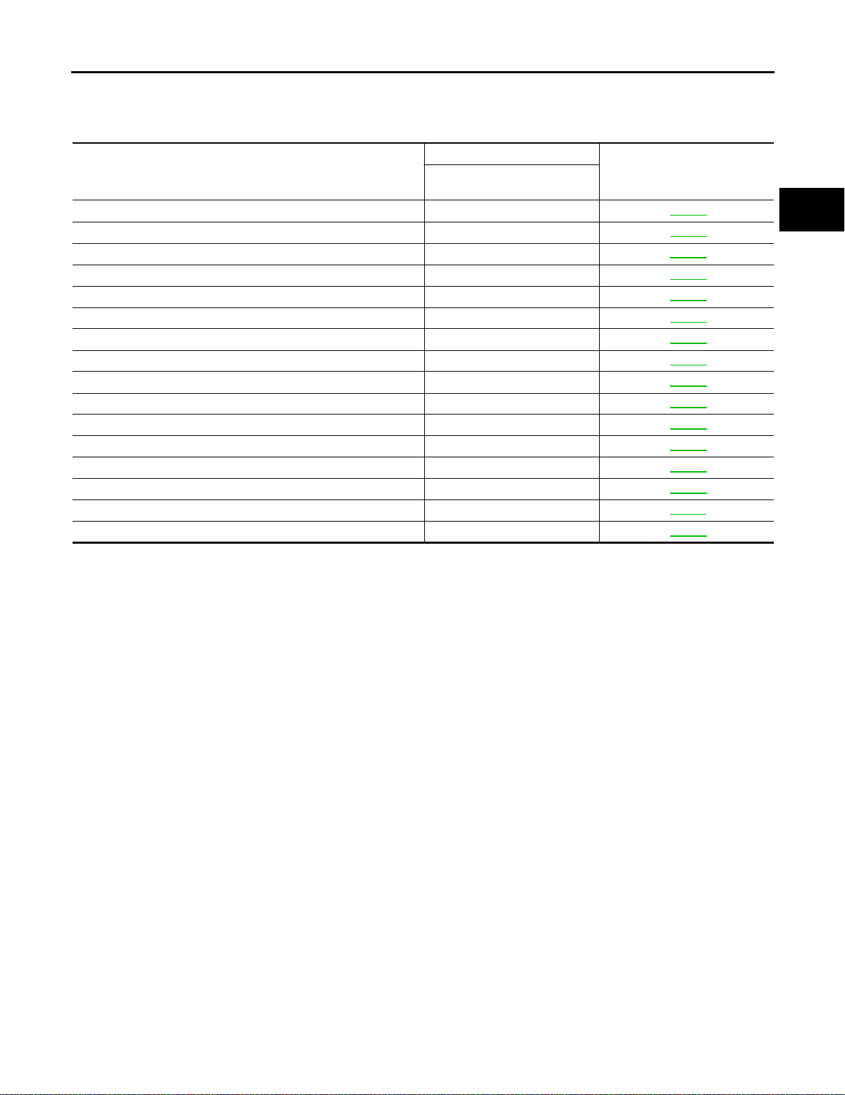
ALPHABETICAL INDEX F OR DTC
Items
(CONSULT-II screen te rms)
A/T 1ST GR FNCTN P0731 AT-124
A/T 2ND GR FNCTN P0732 AT-129
A/T 3RD GR FNCTN P0733 AT-134
A/T 4TH GR FNCTN P0734 AT-139
A/T TCC S/V FNCTN P0744 AT-151
ATF TEMP SEN/CIRC P0710 AT-109
ENGINE SPEED SIG P0725 AT-120
L/PRESS SOL/CIRC P0745 AT-159
O/R CLTCH SOL/CIRC P1760 AT-180
PNP SW/ C IRC P0705 AT-103
SFT SOL A/CIRC* 2 P0750 AT-165
SFT SOL B/CIRC* 2 P0755 AT-170
TCC SOLENOID/CIRC P0740 AT-146
TP SEN/CIRC A/T*2 P1705 AT-175
VEH SPD SEN/ C I R AT*3 P0720 AT-115
CAN COMM CIRCUIT U1000 AT-185
*1: These numbers are prescribed by SAE J2012.
*2: When the fail-safe operation occurs, the MIL illuminates.
*3: The MIL illuminates when both the “Revolution sensor signal” and the “Vehicle speed sensor signal” meet the fail-safe condition at
the same time.
DTC
CONSULT-II
GST*1
Reference page
A
B
AT
D
E
F
G
H
I
J
M
K
L
AT-5
Page 24

TROUBLE DIAGNOSIS - INDEX
P NO. INDEX FOR DTC
DTC
CONSULT-II
GST*1
P0705 PNP SW/CIRC AT-103
P0710 ATF TEMP SE N/CIRC AT-109
P0720 VEH SPD SEN/CIR AT*3 AT-115
P0725 ENGINE SPEED SIG AT-120
P0731 A/T 1ST GR F N CTN AT-124
P0732 A/T 2ND GR FNCTN AT-129
P0733 A/T 3RD GR FNCTN AT-134
P0734 A/T 4TH GR FNCTN AT-139
P0740 TCC SOLENOID/CIRC AT-146
P0744 A/T TCC S/V FNCTN AT-151
P0745 L/PRESS SOL/CIRC AT-159
P0750 SFT SOL A/CIRC*2 AT-165
P0755 SFT SOL B/CIRC*2 AT-170
P1705 TP SEN/CIRC A/T*2 AT-175
P1760 O/R CLTCH SOL/CIRC AT-180
U1000 CAN CO MM CIRCUIT AT-185
*1: These numbers are prescribed by SAE J2012.
*2: When the fail-sa fe operation occurs, the MIL illuminates.
*3: The MIL illuminates when both the “Revolution sensor signal” and the “Vehicle speed sensor signal” meet the fail-safe condition at
the same time.
(CONSULT-II screen terms)
Items
Refe rence page
AT-6
Page 25
PRECAUTIONS
PRECAUTIONS PFP:00001
Precautions f or Supplemental Restraint Syst em (S RS) “AIR BAG” and “SEAT
BELT PRE-TENSIONER”
ECS004QO
A
The Sup plemental Restraint Syste m such as “AIR BAG” and “SEAT BELT PRE-TENSIONER ”, used along
with a fron t seat be lt, hel ps to re duce th e risk or s everity of injur y to th e dr iver and fro nt pass enge r for cer tain
types of collision. Information necessary to service the system safely is included in the SRS and SB section of
this Service Manual.
WARNING:
● To avoid rendering the SRS inoperative, which could increase the risk of personal injury or death
in the eve nt of a collision whic h would result in air bag inflation, all mai ntenance must be performed by an authorized NISSAN/INFINITI dealer.
● Improper mai ntenance, includin g incorrect removal an d installation of the SRS , can lead to per-
sonal injury caus ed by unin te ntional activati on of th e system . For rem oval of Spiral Cab le an d Air
Bag Module, see the SRS section.
● Do not use electrica l test equipm ent on any circ uit related to the S RS unless in structed to in this
Service Manual. SRS wiring harnesses can be identified by yellow and/or orange harness connectors.
Precautions for On Board Diagnostic (OBD) System of A/T and Engin e ECS004QP
The ECM ha s an on board diagnostic system . It will light up the malfun ction indica tor lamp (MIL) to warn the
driver of a malfunction causing emission deterioration.
CAUTION:
● Be sure t o turn the ig nition switc h OFF and disconnect the negative b attery termina l before any
repair or inspection work. The open/short circuit of related switches, sen sors, solenoid valves,
etc. will cause the MIL to light up.
● Be sure to connect and lock the connectors securely after work. A loose (unlocked) connector will
cause the MIL to light up due to an open circuit. (Be sure the connector is free from water, grease,
dirt, bent terminals, etc.)
● Be sure to ro ute and sec ure the harnes ses prope rly a fter wo rk. Int erferenc e of the harn ess with a
bracket, etc. may cause the MIL to light up due to a short circuit.
● Be sure t o conn ec t rubb er tub es p rope rl y afte r wo r k. A mi sco nne cte d o r di s conn ec t ed r ubb er tub e
may cause the MIL to light up due to a malfunction of the EGR system or fuel injection system, etc.
● Be sure to erase the unneces sary malfunction information (repairs completed) from the TCM or
ECM before returning the vehicle to the customer.
B
AT
D
E
F
G
H
I
J
K
Precautions ECS004QQ
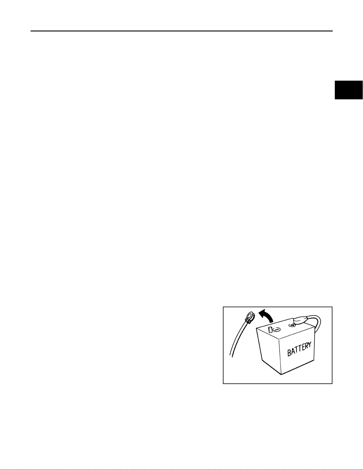
● Before connecting or disconnecting the TCM harness con-
nector, turn ignition switch OFF and disconnect negative
battery terminal. Failure to do so may damage the TCM.
Because b attery voltage is a pplied to TCM even if ign ition
switch is turned off.
SEF289H
AT-7
L
M
Page 26
PRECAUTIONS
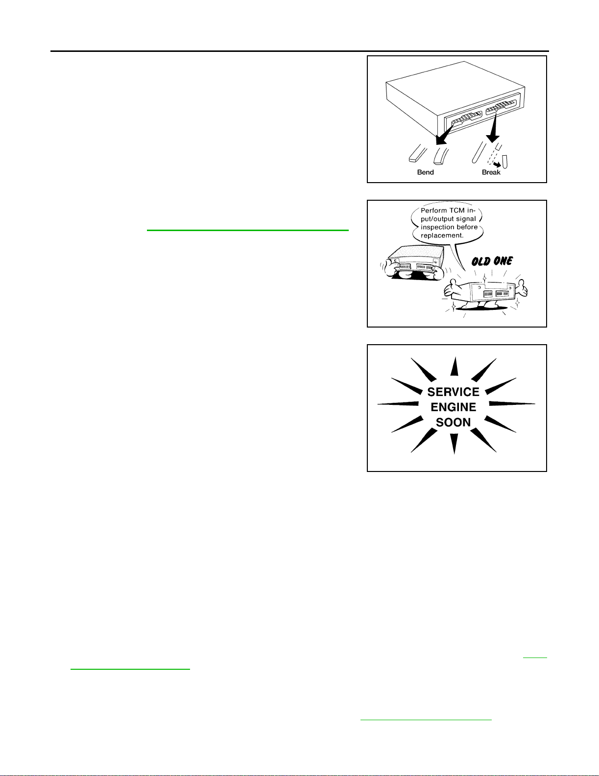
● When co nnecting or disconne cting pin connectors in to or
from TCM, take care not to damage pin terminals ( bend or
break).
Make sure that t here are not any ben ds or breaks on T CM
pin terminal, when connecting pin connectors.
● Before replacing TCM, perform TCM input/output signal
inspection and make su re whether TCM funct ions properly
or not. Ref e r to AT-29, "
INPUT/OUTPUT SIGNAL OF TCM" .
AAT470A
MEF040DA
● After performing each TROUBLE DIAGNOSIS, perform
“DTC (Diagnostic Trouble Code) CONFIRMATION PROCEDURE”.
The DTC should no t be displayed in the “DTC CONFI RMATION PROCEDURE” if t he repair is completed.
● Before p roceeding with disassemb ly, thoroughly clean the out-
side of the transaxle. It is important to prevent the internal parts
from becoming contaminated by dirt or other foreign matter.
● Disassembly should be done in a clean work area.
● Use lint-free cloth or towels for wiping parts clean. Common
shop rags can leave fibers that could interfere with the operation
SAT964I
of the transaxle.
● Place disassembled parts in order for easier and proper assembly.
● All parts should be carefully clea ned with a general pur pose, non-flam mable solve nt before inspec tion or
reassembly.
● Gaskets, seals and O-rings should be replaced any time the transaxle is disassembled.
● It is very important to perform functional tests whenever they are indicated.
● The valve body contains precision parts and requires extreme care when parts are removed and serviced.
Place disassembled valve body parts in order for easier and proper assembly. Care will also prevent
springs and small parts from becoming scattered or lost.
● Properly installed valves, sleeves, plugs, etc. will slide along bores in valve body under their own weight.
● Before assem bly, apply a coat of recommended ATF to all parts. Apply petroleum jelly to pr otect O-rings
and seals, or hold bearings and washers in place during assembly. Do not use grease.
● Extreme c are should be taken to avoid damage to O-rings, seals and gas kets when assembling.
● Replace ATF cooler if excessive f oreign material is fo und in oil pan or cl ogging strainer. Refer to AT-9,
"AT F COOLER SERVICE" .
● After overhaul, refill the transaxle with new ATF.
● When the A/T drai n plug is removed, only some of the fluid is drai ned. Old A/T fluid wil l remain in torque
converter and ATF cooling system.
Always follow the procedures when changing A/T fluid. Refer to MA-29, "
Changing A/T Fluid" .
AT-8
Page 27

PRECAUTIONS
Service Notice or Precautions ECS004QR
FAIL-SAFE
The TCM h as an electr onic Fail-S afe (limp ho me mode) . This allo ws the v ehicle to be driven even i f a major
electrical input/output device circuit is damaged.
Under Fail -Safe, the vehicle a lways runs in thi rd gear, even with a shift lever position of 1, 2 o r D. The customer may complain of sluggish or poor acceleration.
When the ignition key is turned ON following Fail-Safe operation, A/T check (position) indicat or la mp blinks for
about 8 seconds. [For “TCM Self-diagnostic Procedure (No Tools)”, refer to AT-51, "
PROCEDURE (NO TOOLS)" .]
The blinking of the A/T check (position) indicator lamp for about 8 seconds will appea r only once and be
cleared. The customer may resume normal driving conditions.
Always follow the “Work Flow” (Refer to AT-59, "
Work Flow" ).
The SELF-DIAGNOSIS results will be as follows:
● The first SELF-DIAGNOSIS will indicate damage to th e vehicle speed sensor or the revolution sens or.
● During the next SELF-DIAGNOSIS, performed after checking the sensor, no damages will be indicated.
TORQUE CONVERTER SERVICE
The torque converter sho uld be replaced under any of the following conditions:
● External leaks in the hub weld area.
● Converter hub is scored or damaged.
● Converter pilot is broken, damaged or fits poorly into crankshaft.
● Steel particles are found after flushing the cooler and cooler lines.
● Pump is damaged or steel particles are found in the converter.
● Vehicle has TCC shudder and/or no TCC apply. Replace only after all hyd raulic and electr ical diagnose s
have been made. (Converter clutch material may be glazed.)
● Converter is c ontaminated with engine coolant containing antifreeze.
● Internal failu re of stator roller clutch.
● Heavy clutch debris due to ov erheating (bl ue converter).
● Steel particles or clutch lining material found in fluid filter or on magnet when no internal parts in unit are
worn or damaged — indicates that lining material came from converter.
The torque converter shou ld not be replaced if:
● The fluid has an odor, is discolored, and there is no evidence of metal or clutch facing particles.
● The threads in one or more of the converter bolt holes are damaged.
● Transaxle failure did not display evidence of damaged or worn internal parts, steel particles or clutch plate
lining material in unit and inside the fluid filter.
● Vehicle has been exposed to high mileage (only). The exception may be where the torque converter
clutch dampen er plat e lining h as se en exc ess wea r by v ehic les oper ate d in heav y and /or con stant traffic,
such as taxi, delivery or police use.
ATF COOLER SERVICE
If A/T fluid contains frictional material (clutches, bands, etc.), replace radiator and flush cooler line using cleaning solvent and c ompre ssed air after r epair of A/T. Refer to CO-12, "
"RADIATOR" (with VQ35DE).
RADIATOR" (with QR25DE ), or CO-34,
TCM SELF-DIAGNOSTIC
A
B
AT
D
E
F
G
H
I
J
K
L
M
OBD-II SELF-DIAGNOSIS
● A/T self-diagnosis is performed by the TCM in combination with the ECM. The results can be read through
the blinking pattern of the A/T chec k (position ) indicator or th e malfunctio n indicator lamp (MIL). Refe r to
the table on AT-41
● The self-diagnostic results indicated by the MIL are automatically stored in both the ECM and TCM mem-
for the indicator used to display each self-diagnostic result.
ories.
Always perform the pr oced ure “H OW TO ERASE D TC” on AT-38
to complete the repair and avo id
unnecessary blinking of th e MIL.
● The following s elf-diagnostic items can be detected u sing ECM se lf-diagnostic results mo de* only when
the A/T check (position) indicator lamp does not indicate any malfunctions.
– park/neutral position (PNP) switch
– A/T 1st, 2nd, 3rd, or 4th gear function
AT-9
Page 28

PRECAUTIONS
– A/T TCC S/V function (lock-up).
*: For details of OB D-II, re fer to E C-54, "
EC-673, "
● Certain systems and components, especially those related to OBD, may use a new style slide-
ON BOARD DIAGNOSTIC (OBD ) SYSTEM" (with VQ35DE).
ON BOARD DIAGNOSTIC (OBD) SYSTEM" (with QR 25D E), or
locking type harness connector.
For description and how to disconnect, refer to GI-22, "
How to Check Terminal" .
Wiring Diagrams and Trouble Diagnosis ECS004QS
When you read wiring diagrams, refer t o the following:
● GI-12, "How to Read Wiring Diagrams"
● PG-3, "POWER SUPPLY ROUTING CIRCUIT"
When you perform trouble diagnosis, refer to the following:
● GI-10, "HOW TO FOLLOW TEST GROUPS IN TROUBLE DIAGNOSES"
● GI-25, "How to Perform Efficient Diagnosis for an Electrical Incident"
AT-10
Page 29
PREPARATION
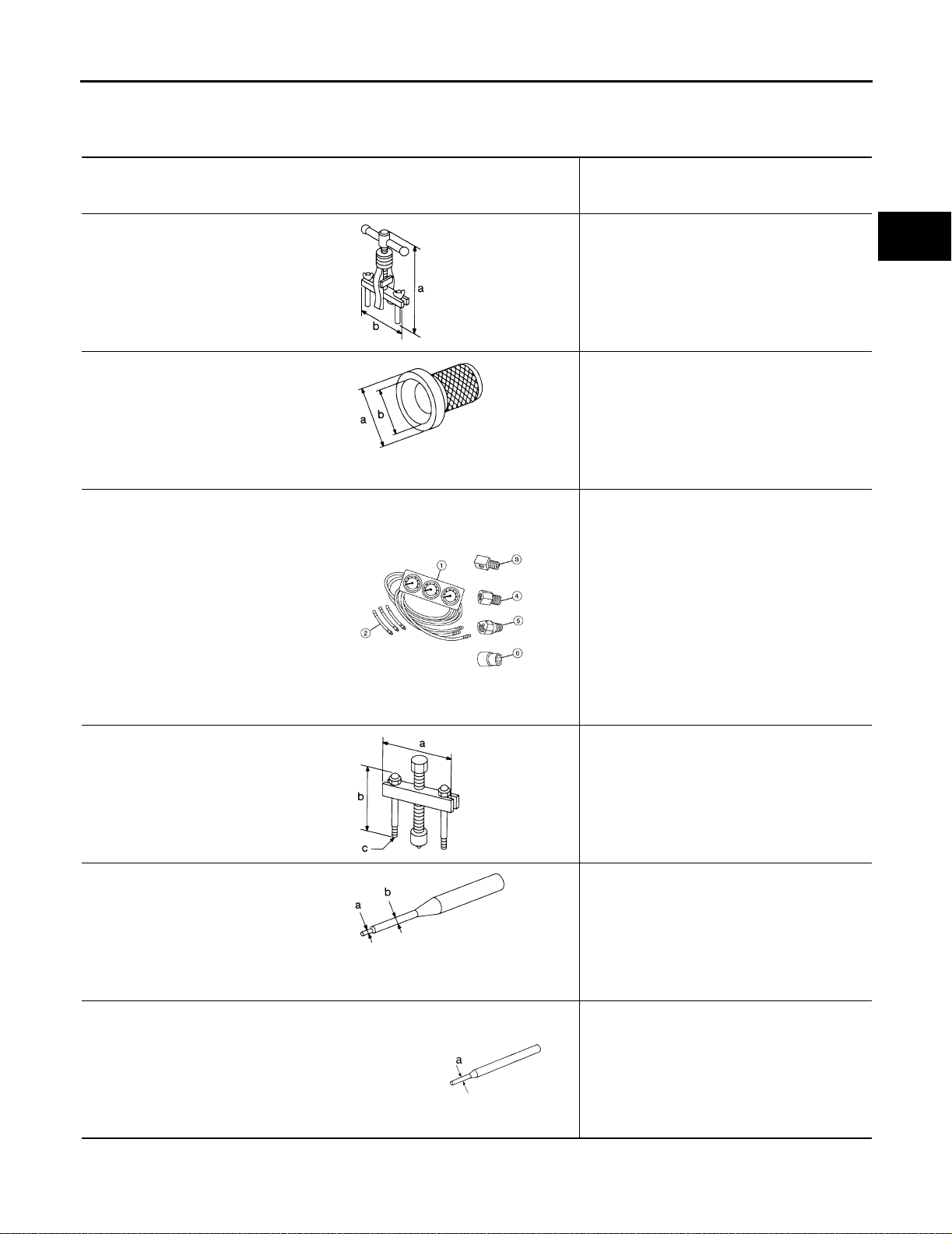
PREPARATION PFP:00002
Special Service T ools ECS004QT
The actual shapes of Kent-M oore tools may differ from those of special service tools illustrated here.
Tool numbe r
(Kent-Moore No.)
Tool name
KV381054S0
(J34286)
Puller
NT414
ST33400001
(J26082)
Drift
Description
● Removing differentia l side oil seals
● Removing differentia l side be aring outer
race
● Removing idler gear bearing outer race
a: 250 mm (9.84 in)
b: 160 mm (6.30 in)
● Installing differential side oil seal
(RH side)
● Installing oil seal on oil pump housing
a: 60 mm (2.36 in) dia .
b: 47 mm (1.85 in) dia.
A
B
AT
D
E
F
(J34301-C)
Oil pressure gauge set
1 (J34301-1 )
Oil pressure gauge
2 (J34301-2 )
Hoses
3 (J34298)
Adapter
4 (J34282-2 )
Adapter
5 (790-301-1230-A)
60° Adapter
6 (J34301-1 5)
Square socket
ST27180001
(J25726-A)
Puller
ST23540000
(J25689-A)
Pin punch
NT086
AAT896
NT424
● Measuring line pressure
● Removing idler gear
a: 100 mm (3.94 in)
b: 110 mm (4.33 in)
c: M8 x 1.25P
● Removing and installing parking rod plate
and manual plate pins
a: 2.3 mm (0.091 in) dia.
b: 4 mm (0.16 in) dia.
G
H
I
J
K
L
M
ST25710000
(J25689-A)
Pin punch
NT442
● Aligni ng groo ve of manu al shaf t and hol e of
transmission case
a: 2 mm (0.08 i n) dia.
NT410
AT-11
Page 30

Tool num ber
(Kent-Moore No.)
Tool nam e
KV32101000
(J25689-A)
Pin punch
KV31102400
(J34285 and J34285-87)
Clutch spring compressor
KV40100630
(J26092)
Drift
PREPARATION
Description
● Removing and installing m anual shaft re-
taining pin
● Removing and installing pinion mate shaft
lock pin
a: 4 mm (0.16 in) dia.
NT410
● Removing and installing clutch return
springs
● Installing low and re verse brake piston
a: 32 0 mm (12.60 in)
b: 17 4 mm (6. 85 in)
NT423
● Installing reduction gear bearing inner race
● Installing idler gear bearing inner race
a: 67.5 mm (2.657 in) d ia.
b: 44 mm (1.73 in) dia.
c: 38.5 mm (1.516 in) d ia.
ST30720000
(J25405 and J34331)
Bearing installer
ST35321000
(—)
Drift
(J34291-A)
Shim setting gauge set
ST33230000
(J25805-01)
Drift
NT107
● Installing idler gear bearing outer race
a: 77 mm (3.03 in) dia.
b: 55.5 mm (2.185 in) d ia.
NT115
● Installing output shaft bearing
a: 49 mm (1.93 in) dia.
b: 41 mm (1.61 in) dia.
NT073
● Selecting oil pump cover bearing race and
oil pump thrust washer
● Selecting side gear thrust washer
NT101
● Installing differentia l side bearing inner race
(RH side)
a: 51 mm (2.01 in) dia.
b: 28.5 mm (1.122 in) d ia.
AT-12
NT084
Page 31
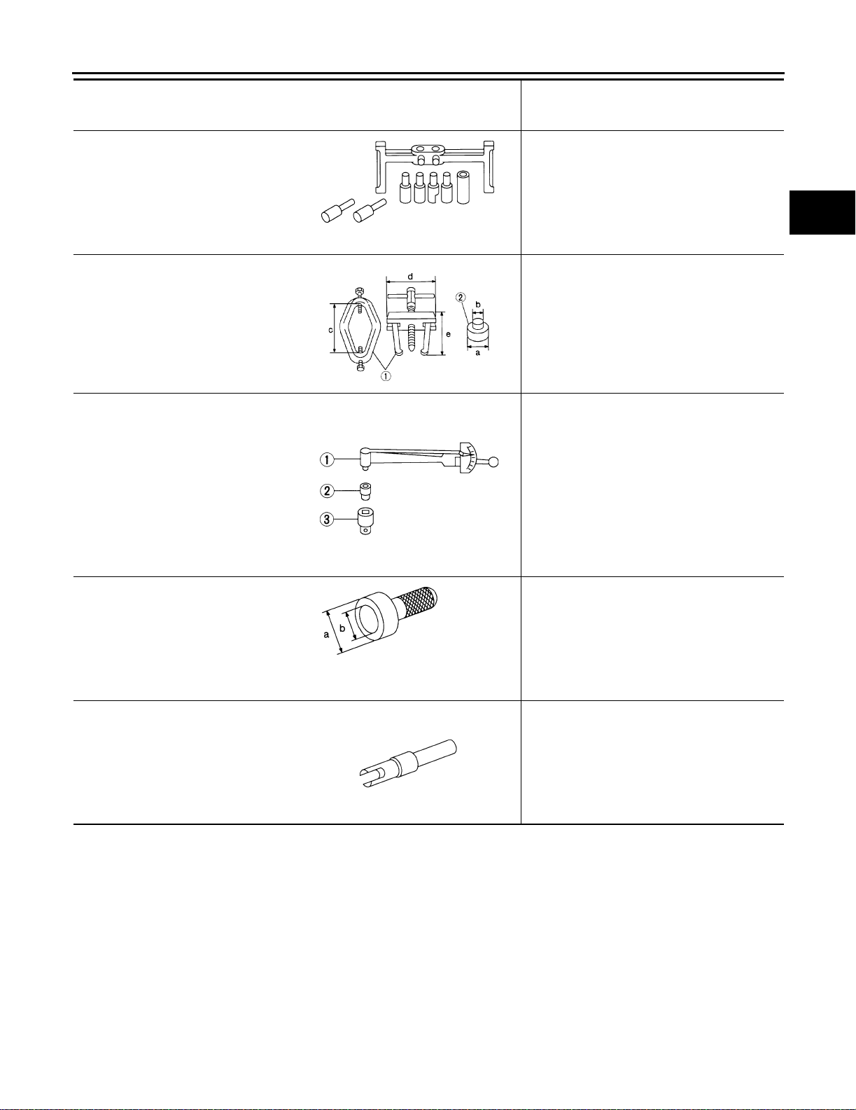
PREPARATION
Tool numbe r
(Kent-Moore No.)
Tool name
(J34290)
Shim selecting tool set
ST3306S001
(J22888-D)
Differ ent i al si de bearing puller set
1 ST330510 01
(J22888-D)
Puller
2 ST330610 00
(J8107-2)
Adapter
ST3127S000
(J25765-A)
Preload gauge
1 GG91030000
(J25765-A)
Torq ue wrench
2 HT62940000
(—)
Socket adapter
3 HT62900000
(—)
Socket adapter
ST35271000
(J26091)
Drift
NT080
AMT153
NT124
Description
● Selecting differential side bearing adjusting
shim
● Removing differentia l side be aring i nner
race
a: 38 mm (1.50 in) dia .
b: 28.5 mm (1.122 in) dia.
c: 130 mm (5.12 in)
d: 135 mm (5.31 in)
e: 100 mm (3.94 in)
● Checking differential side bearing preload
● Installing idler gear
a: 72 mm (2.83 in) dia .
b: 63 mm (2.48 in) dia.
A
B
AT
D
E
F
G
H
I
J
(J39713)
Preload adapter
NT115
NT087
● Selecting differential side bearing adjusting
shim
● Checking differential side bearing preload
K
L
M
AT-13
Page 32
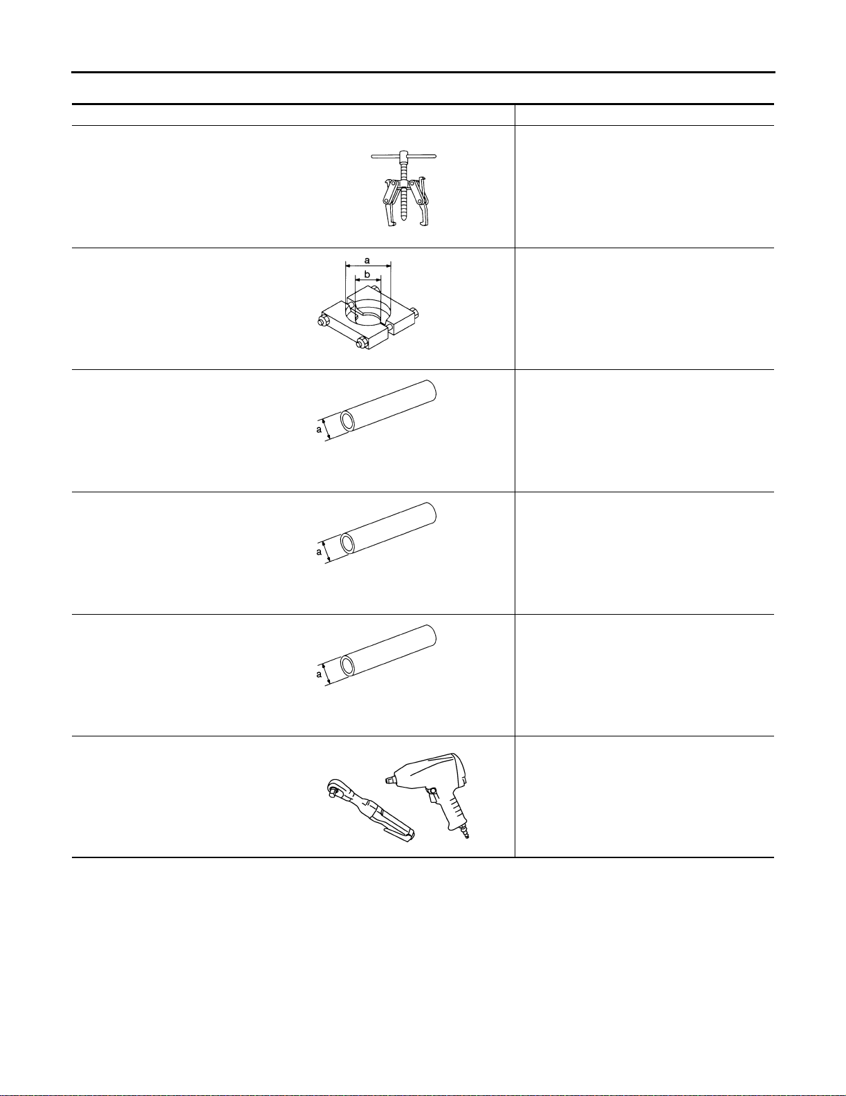
PREPARATION
Commercial Service Tools
Tool nam e Description
Puller
NT077
Puller
NT411
Drift
NT083
Drift
● Removing idler gear bearing inner race
● Removing and installing band servo piston
snap ring
● Removing reduction gear bearing inner
race
a: 60 mm (2.36 in) dia.
b: 35 mm (1.38 in) dia.
● Installing needle bearing on bearing retain-
er
a: 36 mm (1.42 in) dia.
● Removing needle bearing from bearing re-
tainer
a: 33.5 mm (1.319 in) d ia.
ECS004QU
Drift
Power tool
NT083
● Installing differ ential side bearing o uter race
(RH side)
a: 75 mm (2.95 in) dia.
NT083
● Removing transaxle assembly
● Removing transaxle oil pan
● Removing transaxle case and cover
PBIC0190E
AT-14
Page 33
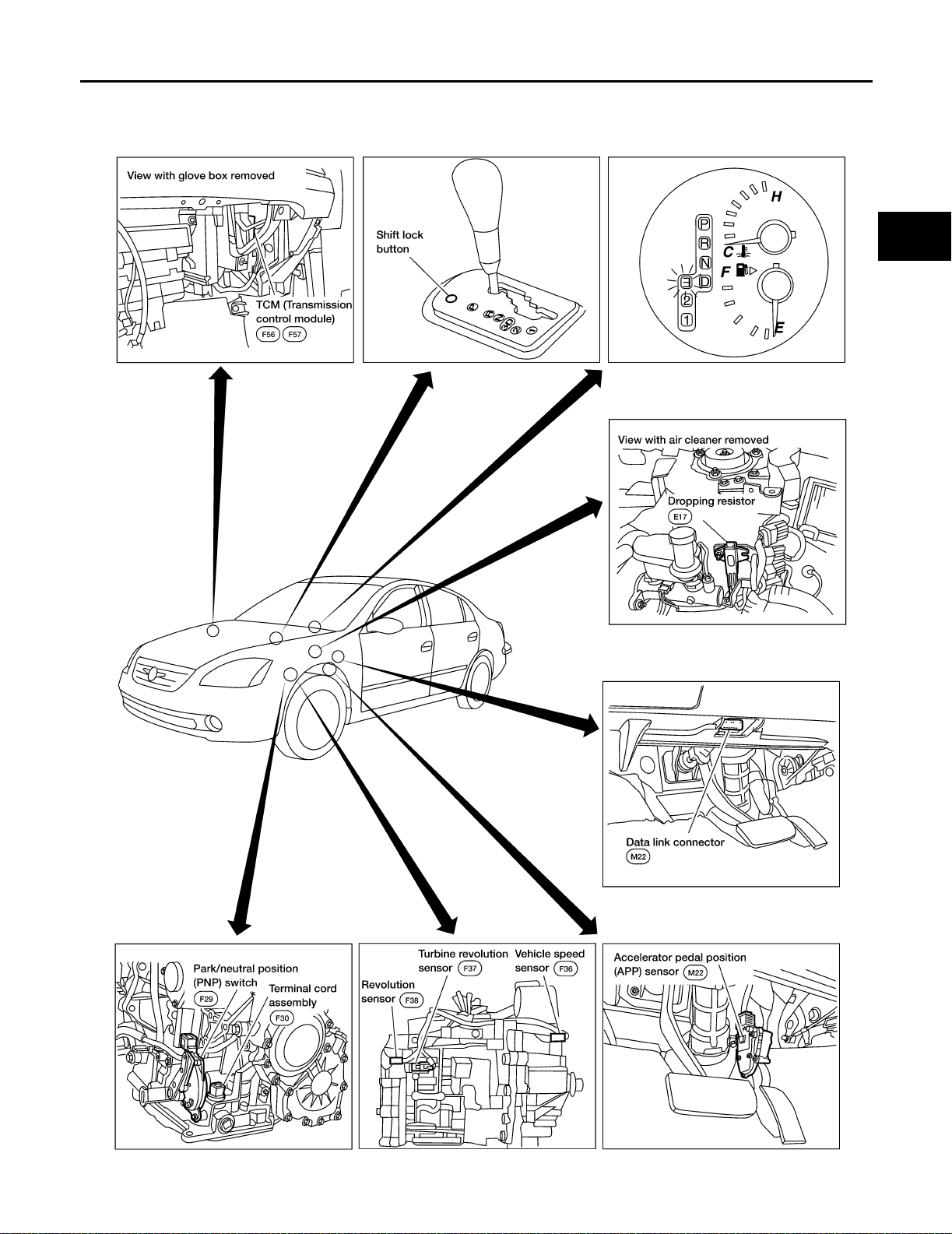
OVERALL SYSTEM
OVERALL SY STEM PFP:00000
A/T Electrical Parts Location ECS004QV
A
B
AT
D
E
F
G
M
H
I
J
K
L
AT-15
LCIA0038E
Page 34
OVERALL SY STEM
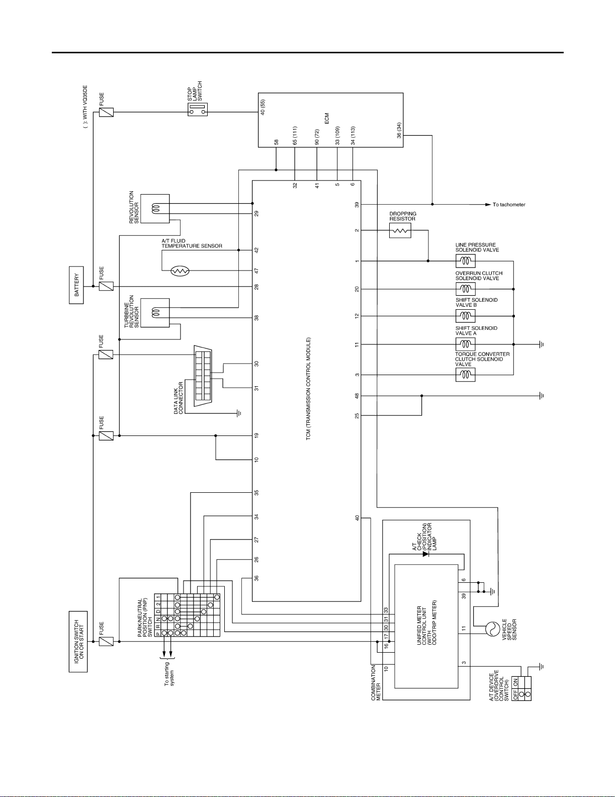
Circuit Diagram
ECS004QW
AT-16
LCWA0029E
Page 35
OVERALL SYSTEM
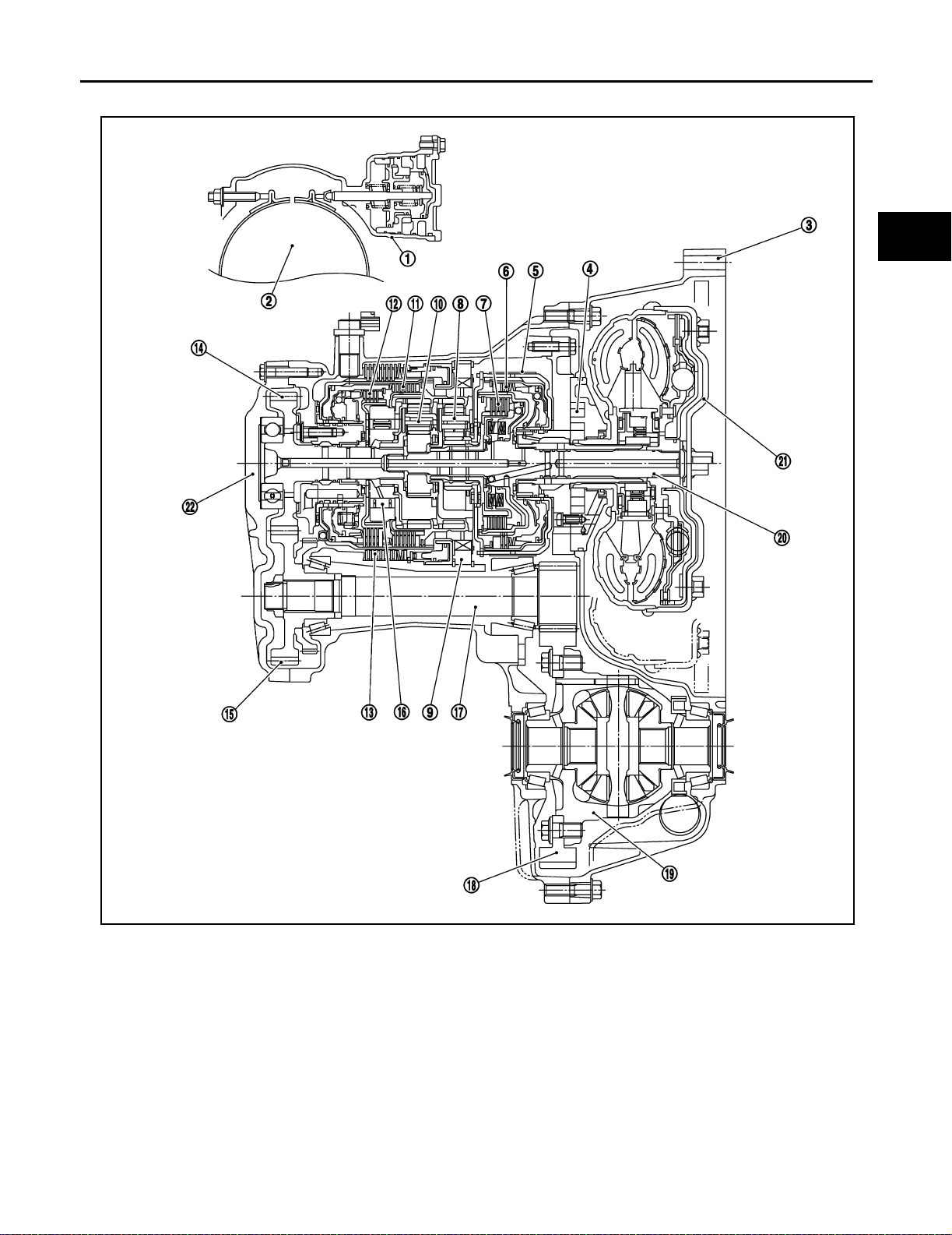
Cross-sectional View ECS004QX
A
B
AT
D
E
F
G
1. Band servo piston 2. Reverse clutch drum 3. Converter housing
4. Oil pump 5. Brake band 6. Reverse clutch
7. High clutch 8. Front planetary gear 9. Low one-way clutch
10. Rear planetary gear 11. Forward clutch 12. Overrun clutch
13. Low & reverse brake 14. Output gear 15. Idler gear
16. Forward one-way clutch 17. Pinion reduction gear 18. Final gear
19. Differential case 20. Input shaft 21. Torque converter
22. Side cover
H
I
J
K
L
M
SAT488K
AT-17
Page 36
OVERALL SY STEM
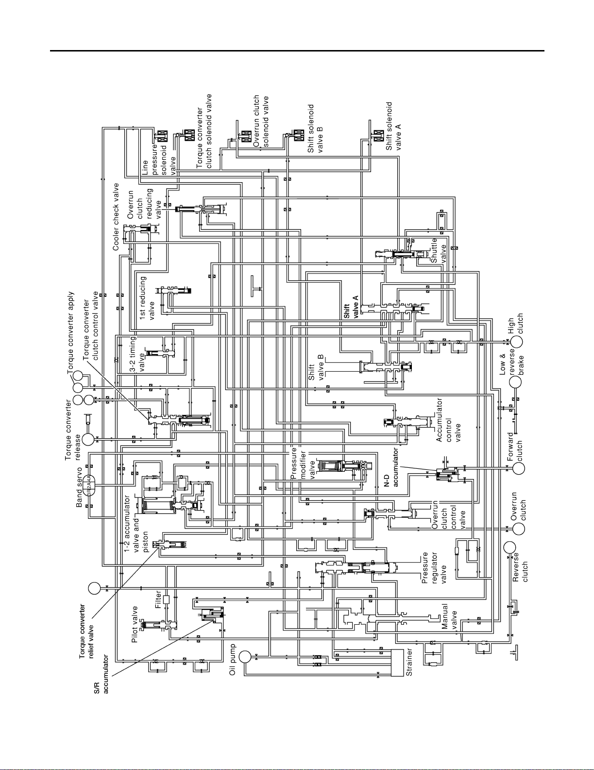
Hydraulic Control Circuit
ECS004QY
AT-18
LCIA0040E
Page 37
OVERALL SYSTEM
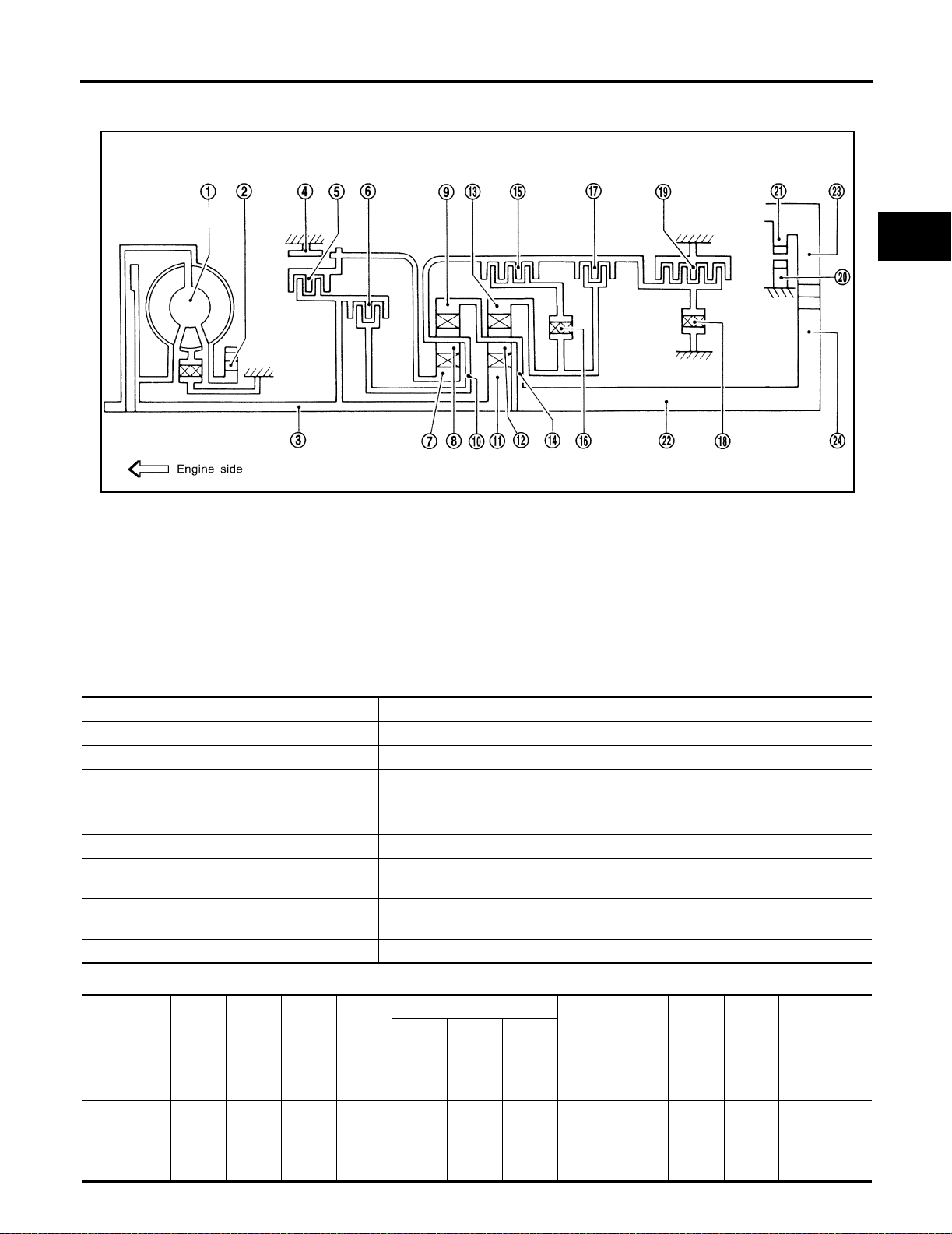
Shift Mechan is m ECS004QZ
CONSTRUCTION
A
B
AT
D
E
F
SAT998I
1. Torque converter 2. Oil pump 3. Input shaft
4. Brake band 5. Reverse clutch 6. High clutch
7. Front sun gear 8. Front pinion gear 9. Front internal gear
10. Front planetary carrier 11. Rear sun gear 12. Rear pinion gear
13. Rear internal gear 14. Rear planetary carrier 15. Forward clutch
16. Forward one-way clutch 17. Overrun clutch 18. Low one-way clutch
19. Low & reverse brake 20. Parking pawl 21. Parking gear
22. Output shaft 23. Idle gear 24. Output gear
FUNCTION OF CLUTCH AND BRAKE
Clutch and brake components Abbr. Function
Reverse clutch 5 R/C To tra nsmit input power to front sun gear 7 .
High clutch 6 H/C To transmit input power to front planetary carrier 10 .
Forward clutch 15 F/C T o co nn ect front planetary ca rri e r 10 with forward one-way clutch
16 .
Overr un clut ch 17 O/C To connect front planetary carrier 10 with rear internal gear 13 .
Brake band 4 B/B To lock front sun gear 7 .
Forward one-way clutch 16 F/O.C When forward clutch 15 is engag ed , t o s top rear internal ge ar 13
from rotating in opposite direction against engine revolution.
Low one-way clutch 18 L/O.C To stop front planetary carrier 10 from rotating in opposite direc-
tion against engine revolution.
Low & revers e brake 19 L & R/B To lock front planetary carrier 10 .
G
H
I
J
K
L
M
CLUTCH AND BAND CHART
Band servo For-
ward
one-
way
clutch
16
15
Over-
run
clutch
17
2nd
apply
3rd re-
lease
4th
apply
Re-
Shift p osition
P
RO O
verse
clutch
High
clutch
5
For-
ward
clutch
6
AT-19
Low
one-
way
clutch
18
Low &
reverse
brake
19
Lock-
up
Remarks
PARK POSI-
TION
REVERSE
POSITION
Page 38

OVERALL SY STEM
Band servo For-
ward
one-
way
clutch
16
15
Over-
run
clutch
17
2nd
apply
3rd re-
lease
4th
apply
Re-
Shift position
N
D*4
2
1
*1: Operates when selector lever is set in 3 position.
*2: Oil pressure is applied to both 2nd “apply” side and 3rd “release” side of band servo piston. However, brake band does not contract
because oil pressure area on the “release” side is greater than that on the “apply” side.
*3: Oil pressure is applied to 4th “apply” side in condition *2 above, and brake band contracts.
*4: A/T will not shift to 4th when selector lever is set in 3 position.
*5: Operates when selector lever is set in 3 position.
O: Operates
A: Operates when throttle opening is less than 3/16, activating engine brake.
B: Operates during “progressive” acceleration.
C: Operates but does not affect power transmission.
D: Operates when throttle opening is less than 3/16, but does not affect engine brake.
verse
clutch
1st O *1D B B
2nd O *1 A O B
3rd O O *1 A *2C C B *5O
4th O C *3C C O O
1st O D B B Automatic
2nd O A O B
1st O O B O Locks (held
2nd OOO B
High
clutch
5
For-
ward
clutch
6
Low
one-
way
clutch
18
Low &
reverse
brake
19
Lock-
up
Remarks
NEUTRAL
POSITION
Automatic
shift
1 ⇔ 2 ⇔ 3
⇔ 4
shift
1 ⇔ 2 ⇐ 3
stati onary) in
1st speed
1 ⇐ 2 ⇐ 3
AT-20
Page 39
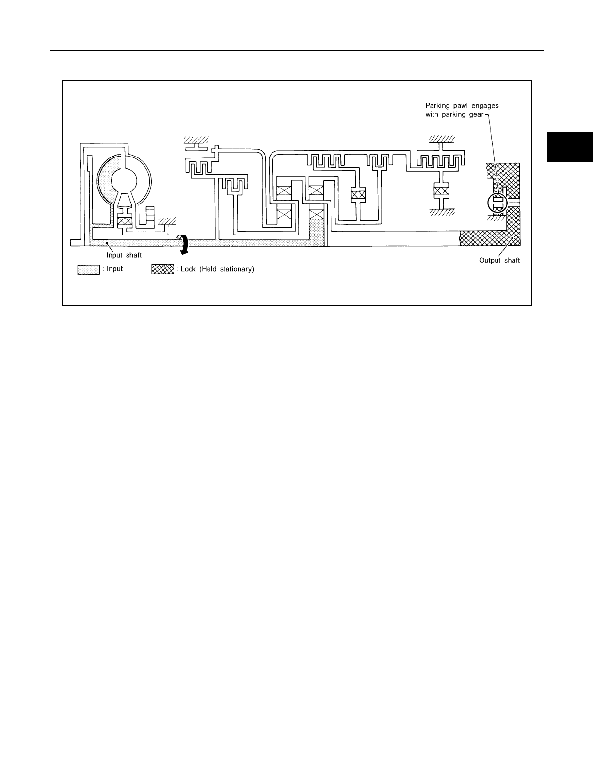
POWER TRANSMISSION
P and N Positions
OVERALL SYSTEM
A
B
AT
D
E
F
● P position
Similar to the N po sition, the cl utche s do not oper ate . The parki ng paw l enga ges wi th the park ing gea r to
mechanically hold the output shaft so that the power train i s locked.
● N position
Power from the input shaft i s not transmi tted to the output shaft becau se the clutches do not operate.
SAT991I
G
H
I
J
K
L
M
AT-21
Page 40
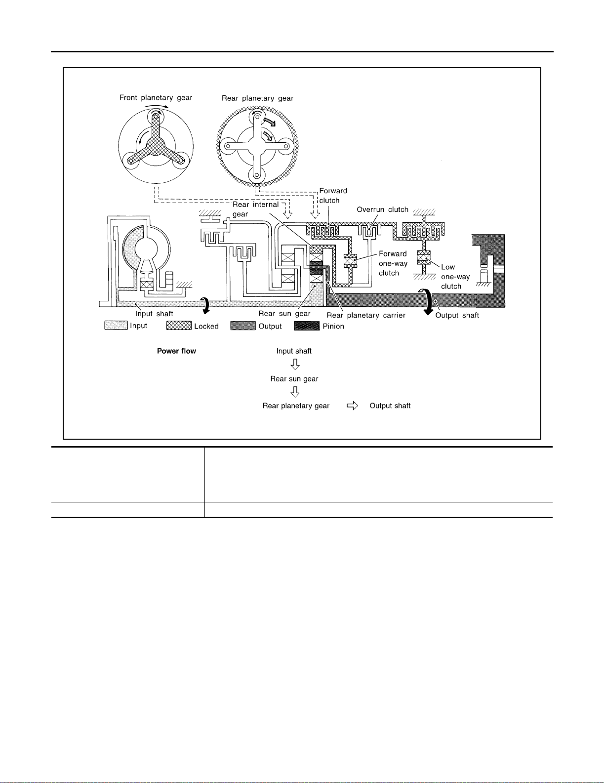
11 Position
OVERALL SY STEM
AAT537A
● Forward clutch
● Forward one-way clutch
● Overrun clutch
● Low and reverse brake
As overrun clutch engages, rear internal gear is locked by the operation of low and reverse
brake.
This is different from that of D
1 , 21 , and 31 .
Engine brake Overrun clutch always engages, therefore engine brake can be obtained when decelerating.
AT-22
Page 41
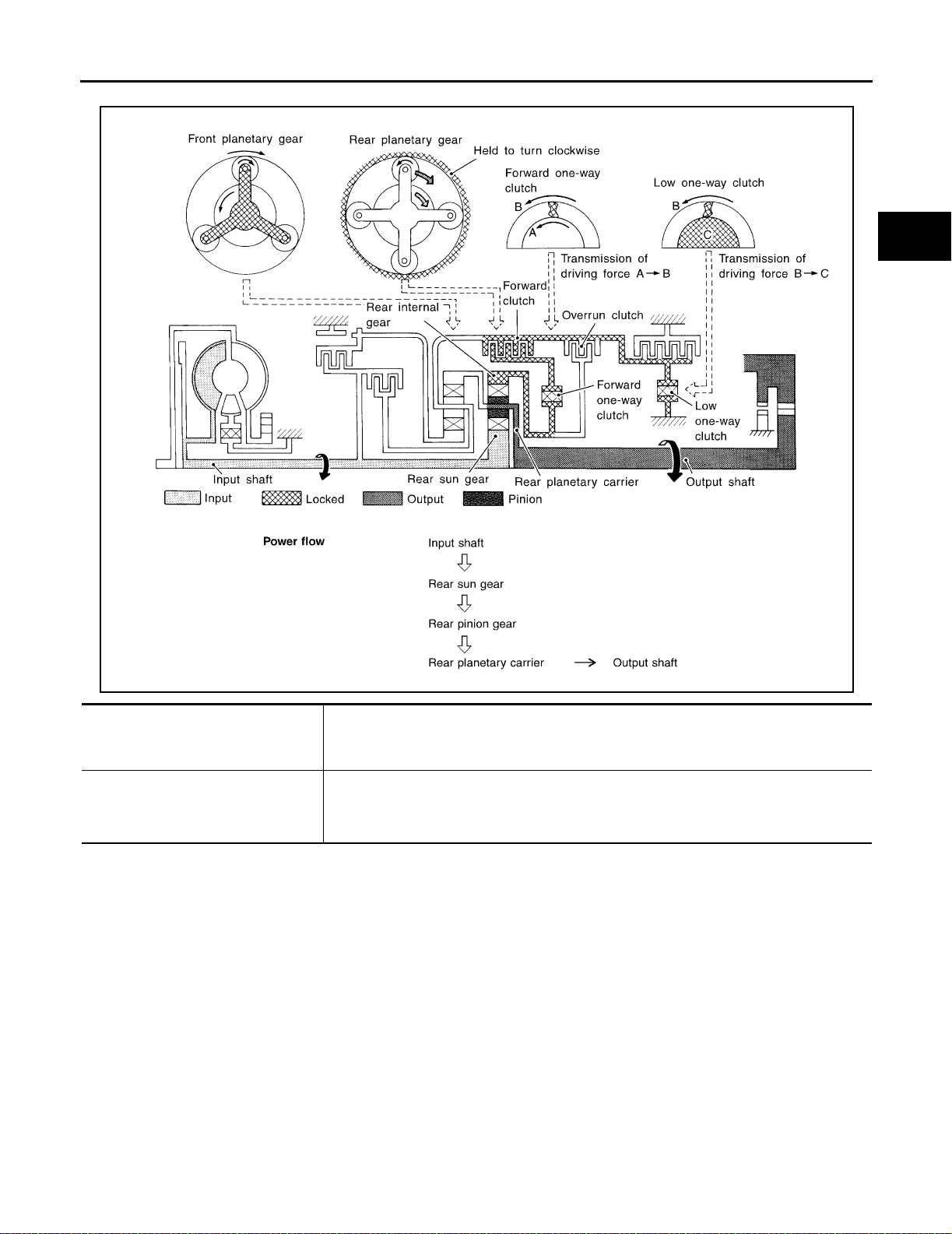
D1 and 21 Positions
OVERALL SYSTEM
A
B
AT
D
E
F
G
● Forward one-way clutch
● Forward clutch
● Low one-way clutch
Overr un clutch
engagement conditions
(Engine brake)
AAT532A
Rear internal gear is locked to rotate counterclockwise because of the functioning of these
three clutc hes.
D
1 : Gear selector lever is set in 3 p osition and throttle opening is less than 3/16
2
1 : Always engaged
1 and 21 positions, engine brake is not activated due to free turning of low one-way
At D
clutch.
H
I
J
K
L
M
AT-23
Page 42
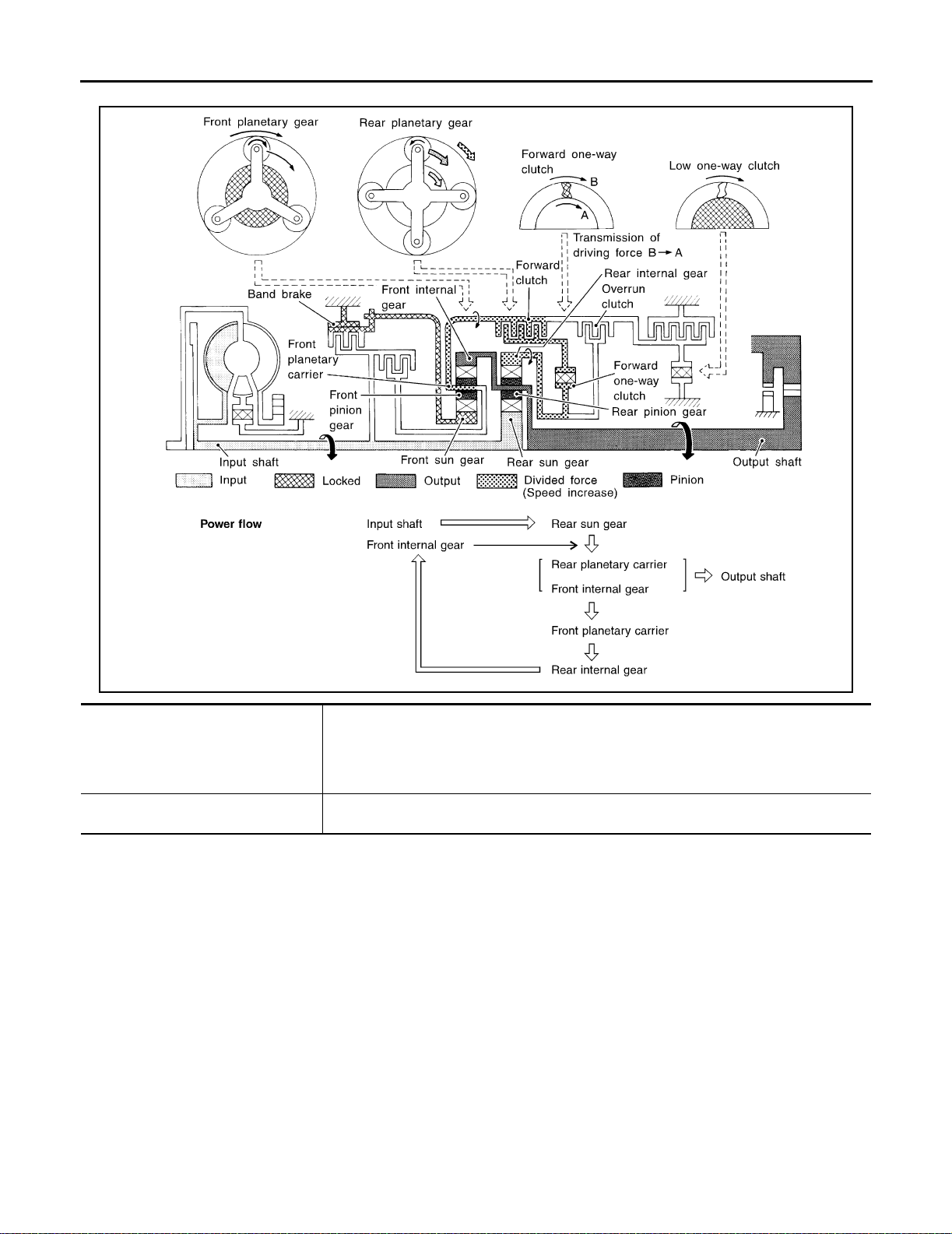
D2 , 32 , 22 and 12 Positions
OVERALL SY STEM
● Forward clutch
● Forward one-way clutch
● Brake band
Overrun clutch
engagement conditions
AAT533A
Rear sun gear drives rear planetary carrier and combined front internal gear. Front internal
gear now rotates around front sun gear accompanying front planetary carrier.
As front pl anet ar y carri er tr ansfer s the po wer to r ear int erna l gea r through forw ard c lutch and
forward one-way clutch, this rotation of rear internal gear increases the speed of rear planetary carrier compared with that of the 1st speed.
3
2 : Gear selector lever is set in 3 position and throttle opening is less than 3/16
3
2 , 22 and 12 : Always engaged
AT-24
Page 43
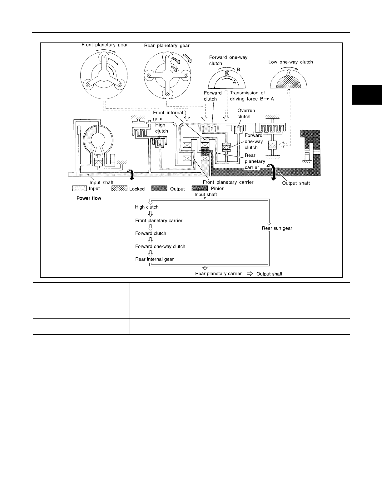
D3 and 33 Posi tions
OVERALL SYSTEM
A
B
AT
D
E
F
G
● High clutch
● Forward clutch
● Forward one-way clutch
Overr un clutch
engagement conditions
AAT534A
Input power is transmitted to front planetary carrier through high clutch. And front planetary
carrier i s connected to rear internal gear by operation of for ward clutch and forward one-way
clutch.
This rear internal gear rotation and another input (the rear sun gear) accompany rear planetary carrier to turn at the sa me speed.
D
3 and 33 : Selector lever is set in 3 position and throttle opening is less than 3/16
H
I
J
K
L
M
AT-25
Page 44
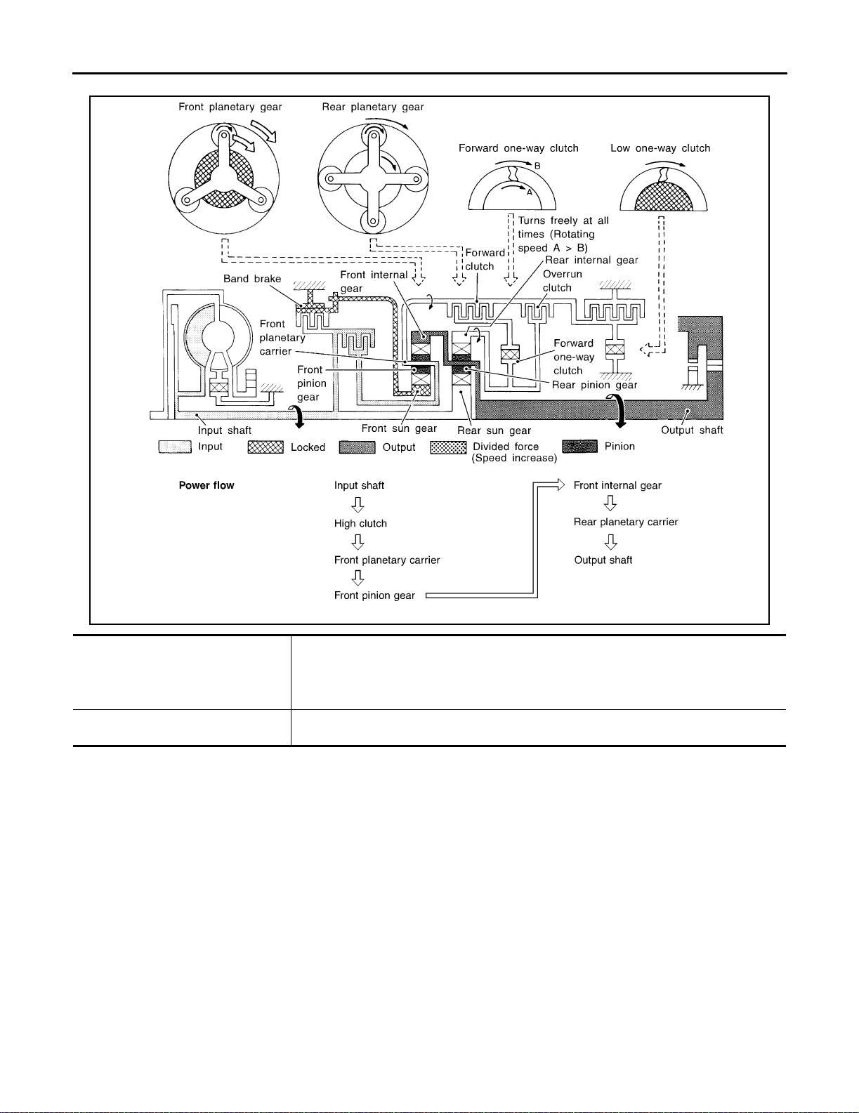
D4 Position
OVERALL SY STEM
● High clutch
● Brake band
● Forward clutch (Does not affect
power transmission)
Engine brake At D
Input power is transmitted to front carrier through high clutch.
This front carrier turns around the sun gear which is fixed by brake band and makes front
internal gear (output) turn faster.
can be obtained when decelerating.
AAT536A
4 position, there is no one-way clutch in the power transmission line and engine brake
AT-26
Page 45
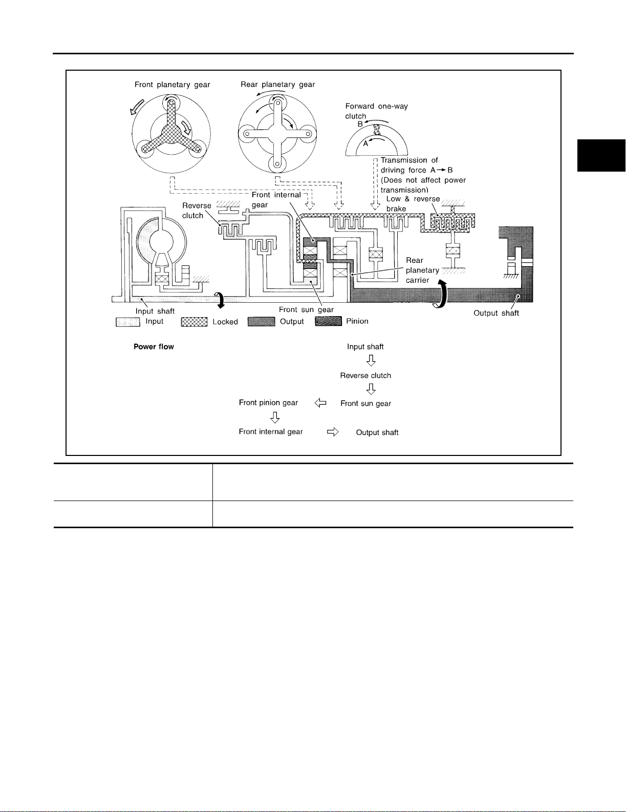
R Position
OVERALL SYSTEM
A
B
AT
D
E
F
G
AAT535A
● Reverse clu tch
● Low and reverse brake
Engine brake As there is no one-way clutch in the power transmission line, engine brake can be obtained
Front planet ary carrier is stationary because of th e operation of low a nd reverse br ake.
Input power is trans mitted to front sun gear through reve rse clutch, which drives front internal gear in the opposite direction.
when decelerating.
H
I
J
K
L
M
AT-27
Page 46
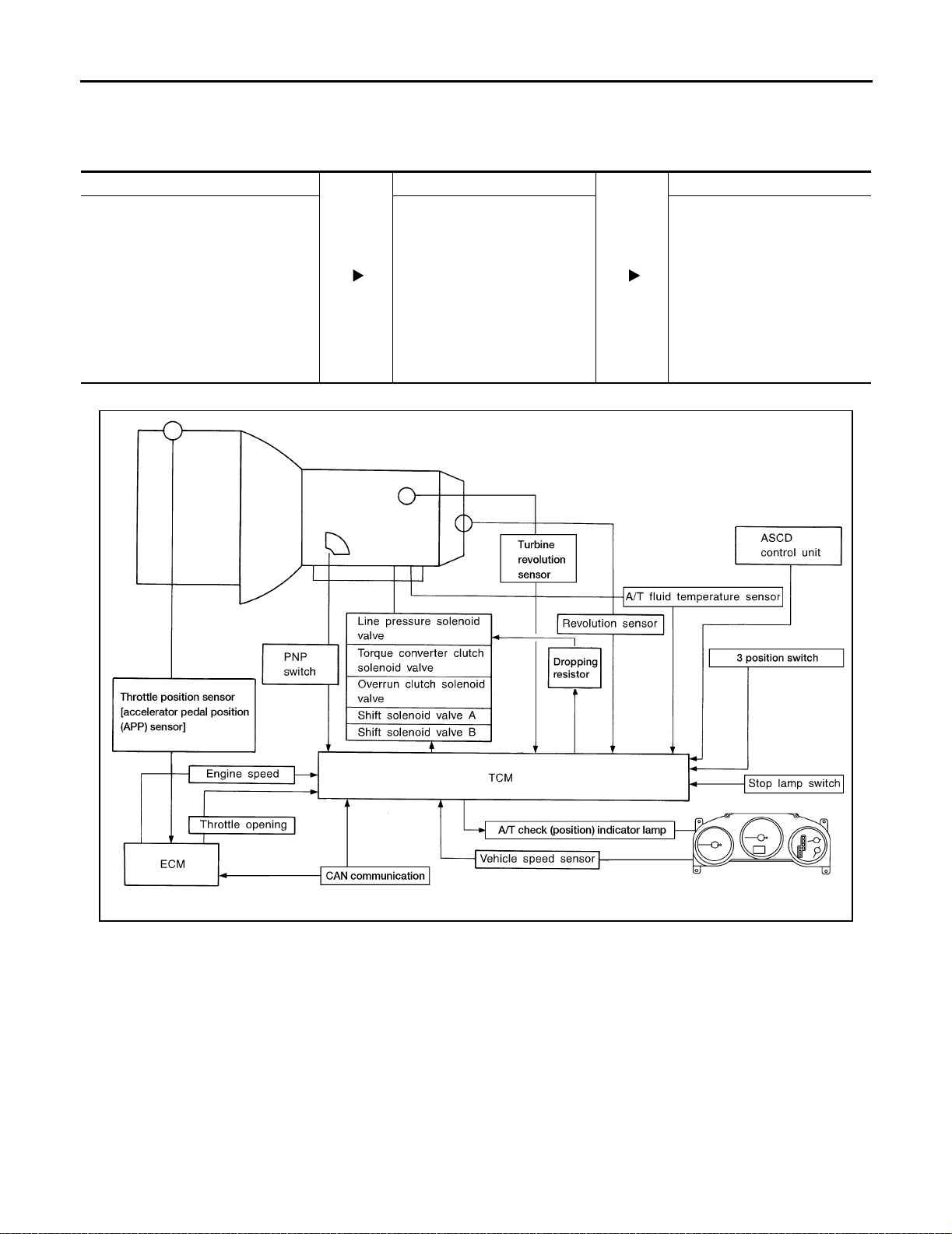
OVERALL SY STEM
Control System
ECS004R0
OUTLINE
The automatic tr ansaxle senses v ehicle operating condi tions through variou s sensors. It alwa ys controls the
optimum shift position and reduces shifting and lock-up shocks.
SENSORS TCM ACTUATORS
Park/neutral position (PNP) switch
Throttle position sensor [accelerator
pedal positi on (APP ) sensor]
Engine speed signal
A/T fluid temperature sensor
Revolution sensor (VHCL/S SE-1)
Vehicle speed sensor (VHCL/S SE-2)
3 position switch
ASCD control unit
Stop lamp switch
Turbine revolution sensor
Shift control
Line pressure control
Lock-up control
Overrun cl utch control
Timing control
Fail-safe control
Self-diagnosis
CAN communication line control
Shift solenoid valve A
Shift solenoid valve B
Overr un clutch solenoi d valve
Torque conve rte r clut ch s ole noid
valve
Line pressure solenoid valve
A/T check (position) indicator
lamp
CONTROL S YST E M
AT-28
LCIA0041E
Page 47

OVERALL SYSTEM
TCM FUNCTION
The function of the TCM is to:
● Receive input signals sent from various switches and sensors.
● Determine required line pressure, shifting point, lock-up operation, and engine brake operation.
● Send required output signals to the respective solenoids.
INPUT/OUTPUT SIGNAL OF TCM
Sensors and sol en oid valves Function
Park/neutral position (PNP) switch Detects select lever position and sends a signal to TCM.
Input
Output
Throttle position sensor [accelerator
pedal position (APP) sensor]
Engine speed signal Receives signal from ECM and controls lock-up control solenoid valve.
A/T fluid temperature sensor Detects transmission fluid temperature and sends a signal to TCM.
Revolution sensor (VHCL/S SE-1) Detects output shaft rpm and sends a signal to TCM.
Ve hicle speed sensor (V HC L/S SE-2)
3 position switch Sends a signal, which prohibits a shift to D
ASCD control unit
Stop lamp switch Send the lock-up release signal to the TCM at time of D
CAN communic ation
Shift solenoid valve A/B
Line pressure solenoid valve
Torque converter clutch solenoid
valve
Overrun clu t ch solenoid valve
A/T check (position) indicator lamp Shows TCM faults, when A/T control components malfunction.
CAN communic ation
Detects throttle valve position and sends a signal to TCM.
Used as an auxiliary ve hicle speed sensor. Send s a signal when revolution
sensor (installed on transmission) malfunctions.
4 (overdrive) p osition, to the TCM.
Sends the cruise signal and D
control unit to TCM.
In CAN communication, control units are connected to 2 communication lines
(CAN H line, CAN L line) allowing a high rate of information transmission with
less wiring.
Selects shifting point suited to driving conditions in relation to a signal sent
from TCM.
Regulates (or decreases) line pressure suited to driving conditions in relation
to a signal sent from TCM.
Regulate s (or dec reases) lock-up pressur e suited to drivi ng con ditions in relation to a signal sent from TCM.
Controls an “engine brake” effect suited to driving conditions in relation to a
signal sent from TCM.
In CAN communication, control units are connected to 2 communication lines
(CAN H line, CAN L line) allowing a high rate of information transmission with
less wiring.
4 (overdrive) cancellation signal from ASCD
4 (lock-up).
A
B
AT
D
E
F
G
H
I
J
K
L
AT-29
M
Page 48
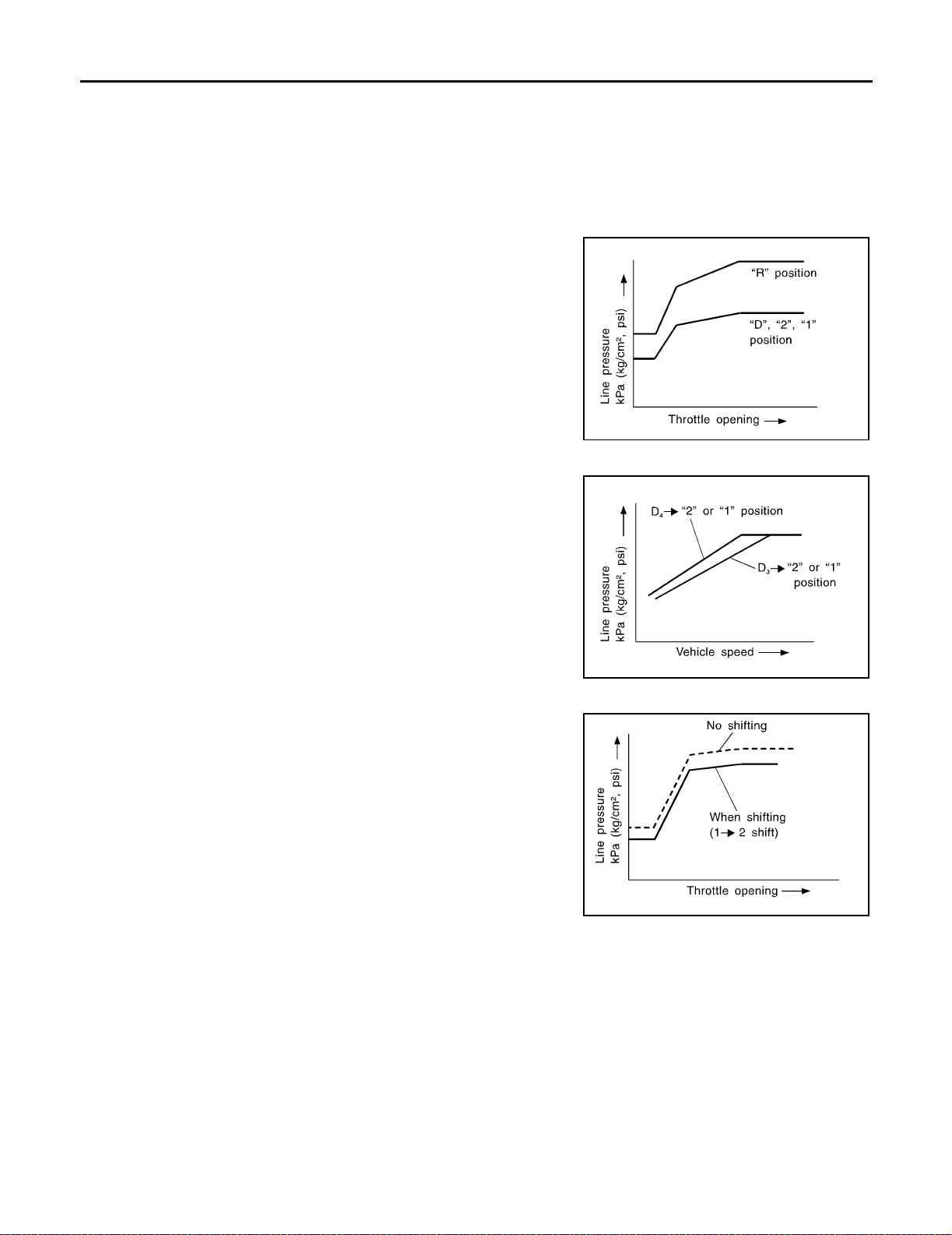
OVERALL SY STEM
Control Mech anis m
ECS004R1
LINE PRESSURE CONTROL
TCM has various line pressure control characteristics to meet the driving conditions.
An ON-OFF duty signal is s ent to the line pressure solenoid valve based on TCM characteristics.
Hydraulic pressure on the clutch and brake is electronically controlled through the line pressure solenoid valve
to accommodate engine torque. This results in smooth shift operation.
Normal Control
The line pressure to throttle opening characteristics is set for suitable
clutch operation.
SAT003J
Back-up Control (Engine brake)
If the selector lever is shifte d to 2 position while drivi ng in D4 (O/D)
3 , great driving force is applied to the clutch inside the transmis-
or D
sion. Clutch oper ating pr ess ure (lin e pressu re) mus t be incre ased to
deal with this driving force.
SAT004J
During Shift Change
The line pressure is temporarily red uced correspond ing to a change
in engine torque whe n sh ifting gear s (that is, when the shift soleno id
valve is switched for clutch operation) to reduce shifting shock.
SAT005J
At Low Fluid Temperature
● Fluid viscosity and frictional characteristics of the clutch facing change with fluid temperature. Clutch
engaging or band-contacting pressure is compensated for, according to fluid temperature, to stabilize
shifting quality.
AT-30
Page 49
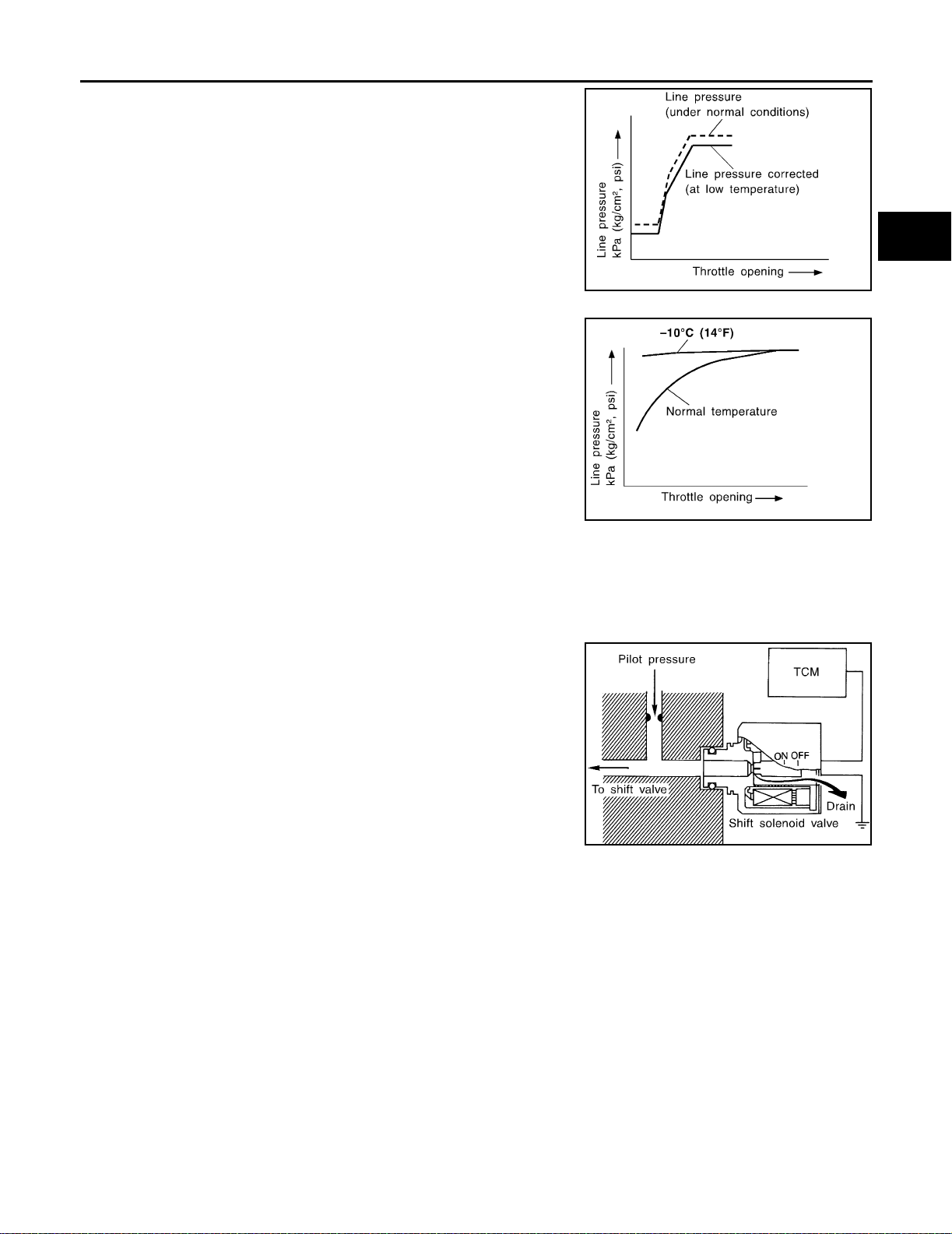
OVERALL SYSTEM
● The line pressure is reduced below 60°C (140°F) to prevent
shifting shock due to low viscosity of automatic transmission
fluid when temperature is low.
● Line pressure is increased to a maximum irrespective of the
throttle opening w hen fluid temperature drops to −10°C (14°F).
This pressure rise is adopted to pr event a d elay in clutch and
brake operation due to extreme drop of fluid viscosity at low
temperature.
A
B
AT
SAT006J
D
E
F
G
SAT007J
SHIFT CONTROL
The shift is regulated entir ely by electronic co ntrol to accommodate vehicle speed and v arying engin e operations. This is accompl ished by electrical signals transmitte d by the revolution sensor and the EC M (throttle
opening). This results in improved acceleration performance and fuel economy.
Control of Shift Solenoid Valves A and B
The shift solenoid v alve performs simple ON-OFF operation. When
set to ON, the drain circuit closes and pilot pressur e is applied to the
shift valve.
The TCM activate s shift solenoid valves A and B accordin g to signals from the E CM ( thro ttle op ening) and revo lutio n sen sor to se lect
the optimum ge ar positio n on the basis of the shift sche dule me morized in the TCM.
SAT008J
H
I
J
K
L
M
AT-31
Page 50
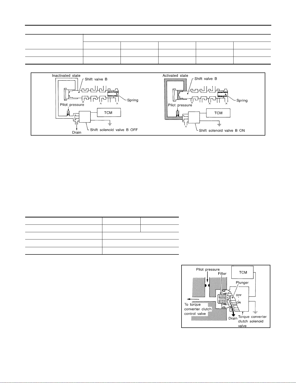
OVERALL SY STEM
Relation between shift solenoid valves A and B and gear positions
Shift solenoid valve
A ON (Closed) OFF (Open) OFF (Open) ON (Closed) ON (Closed)
B ON (Closed) ON (Closed) OFF (Open) OFF (Open) ON (Closed)
D
1 , 21 , 11 D2 , 22 , 1 2 D3 , 33 D4 (O/D) N-P
Control of Shift Valves A and B
Pilot pressure ge nerated by the ope ration of shift solenoi d valves A and B is app lied to the end face of shift
valves A and B.
The drawing above shows th e oper ation of s hift val ve B. W hen th e shift s olenoid valve is ON, pil ot pressur e
applied to th e end face of the shift valve overcomes spring force, moving the valve upward.
Gear positi on
SAT009J
LOCK-UP CONTROL
The torque converter clutch piston in the torque converter is locked to eliminate torque converter slip to
increase power tr ansmission efficiency. The solenoid valve is controlled by an ON-OFF duty signal sent fr om
the TCM. The signal is co nverted to an oil pressure signal which controls the lock-up piston.
Conditions for Lock-up Operation
When vehicl e is driven in 4th gear position, vehicl e speed and thr ottle opening are d etected. If the dete cted
values fall within the lock-up zone memor ized in the TCM, lock-up is performed.
Selector lever D position 3 position
Gear position D
Vehicle speed sensor More than se t value
ECM (throttle opening) Less than set opening
A/T fluid tem perature sen sor More th an 40°C (104°F)
4 3
Torque Converter Clutch Solenoid Valve Control
The torque converter clutch so lenoid valve is co ntrol led by the TCM.
The plunger closes the drain circuit during the OFF period, and
opens the circuit during the ON period. If the percentage of OFF-time
increases in one cycle, the pilot pressure drain time is reduced and
pilot pressure remains high.
AT-32
SAT010J
Page 51
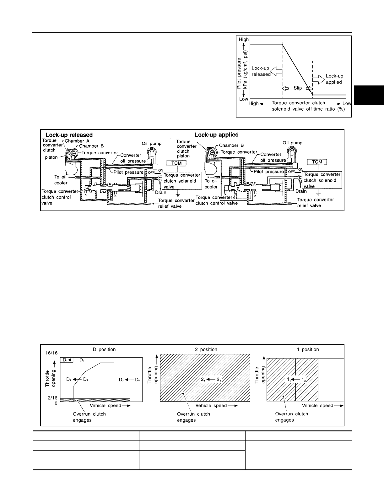
OVERALL SYSTEM
The torqu e converter c lutch piston is designed to sl ip to adjust th e
ratio of ON-OFF, thereby reducing loc k-up shock.
OFF-time INCREASING
↓
Amount of drain DECREASING
↓
Pilot pressure HIGH
↓
Lock-up RELEASING
Torque Converter Clutch Control Valve Operation
A
B
AT
SAT011J
D
E
F
G
AAT155A
LOCK-UP RELEASED
The OFF-durati on of the torque converter clutc h solenoid valve is long, and pilot pressur e is high. The pilot
pressure push es the en d face of the tor que converte r clutch contr ol valve in com bination w ith spring fo rce to
move the valve to the left. As a result, converter pressure is applied to chamber A (torque converter clutch piston release s ide). Accordingly, the torque converter clutch piston remains unlocked.
LOCK-UP APPLIED
When the OFF-duration of the torque converter clutch solenoid valve is short, pilot pressure drains and
becomes low. Accordingly, the control valve moves to the right by the pilot pr essure of the other circuit and
converter pressure. As a resul t, converter pressure is applied to cham ber B, keeping the torque converter
clutch piston applied.
Also smooth lock-up is provided by transient application and release of the lock-up.
OVERRUN CLUTCH CONTROL (ENGINE BRAKE CONTROL)
Forward o ne-way clutch is used to reduce s hifting shocks in downshifti ng operations. This clutch trans mits
engine torqu e to the wheels. How ever, drive force from the wheel s is not transmitted to th e engine becaus e
the one-way clutch rotates idle. This means the engine brake is not effective.
The overrun clutch operates when the engine brake is needed.
Overrun Clutch Operating Conditions
H
I
J
K
L
M
SAT014J
Selector lever position Gear position Throttle opening
DD
22
111 , 12 At any positio n
1 , D2 , D3
1 , 22
Less than 3/16
AT-33
Page 52
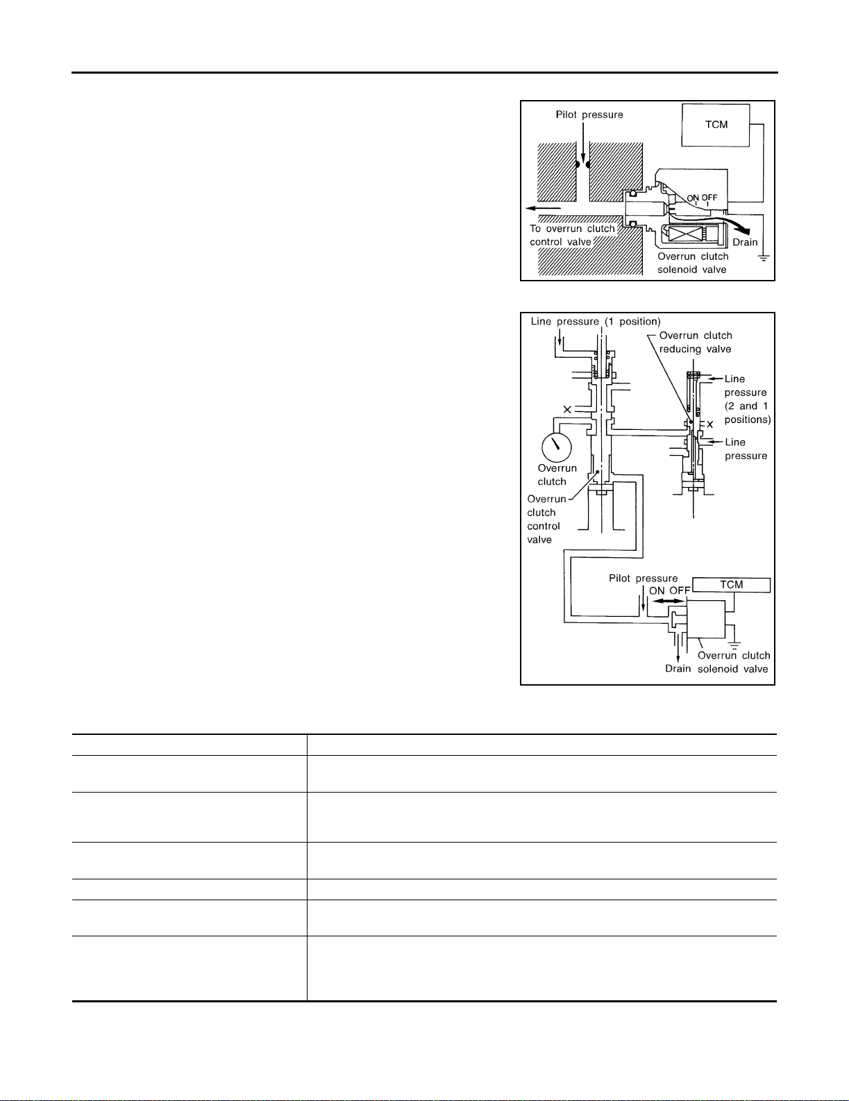
OVERALL SY STEM
Overrun Clutch Solenoid Valve Control
The overrun clutch s olenoid valve is ope rated by an O N-OFF signal
transmitted by the TCM to provide overrun clutch control (engine
brake control).
When this sol eno id valve is ON , the pilot pressu re d rain p ort c lose s.
When it is OFF, the drain port opens.
During the solenoid valve ON pilot pressure is applied to the end
face of the overrun clutch control valve.
Overrun Clutch Control Valve Operation
When the solenoid v alve is ON , pilot press ure is appli ed to the over run clutch cont rol valve. This pushes up the overrun clutch control
valve. The line pr essure is then shu t off so that the clutc h does not
engage.
When the solenoid v alve is OFF, pilo t pressure is not generated. At
this point, the overrun clutch control valve moves downward by
spring force. As a result, overrun clutch operation pressure is provided by the overrun clutch reducing valve. This causes the overrun
clutch to engage.
In the 1 position, the overrun clutch control valve remains pushed
down so that the overrun clutch is engaged at all times.
SAT015J
SAT016J
Control Valve ECS004R2
FUNCTION OF CONTROL VALVES
Valve name Function
Pressure regulator valve, plug and sleeve
plug
Pressure modifier valve and sleeve Used as a signal supplementary valve to the pressure regulator valve. Regulates pres-
Pilot valve Regulates line pressure to maint ain a constan t pilot pressure level which controls lock -up
Accumulator control valve Regulates accumulator back-pressure to pressure suited to driving conditions.
Manual valve Directs line pressure to oil circuits corresponding to select positions.
Shift valve A Simultaneously switches three oil circuits using output pressure of shift solenoid valve A
Regulates oil discharged from the oil pump to provide optimum line pressure for all driving conditions.
sure-modifier pressure (signal pressure) which controls optimum line pressure for all
driving conditions.
mechanism, overrun clutch, shift timing.
Hydraulic pressure drains when the shift lever is in Neutral.
to meet driving conditions (vehicle speed, throttle opening, etc.).
Provides automatic downshifting and up-shifting (1st → 2nd → 3rd → 4th gears/4th →
3rd → 2nd → 1st gears) in combination with shift valv e B.
AT-34
Page 53

OVERALL SYSTEM
Valve name Function
Shift val ve B Simultaneousl y sw i tches two oil cir cu its using output p ressure of shift so l en oi d valve B in
relation to driving conditions (vehicle speed, throttle opening, etc.).
Provides automatic downshifting and up-shifting (1st → 2nd → 3rd → 4th gears/4th →
3rd → 2nd → 1st gears) in combination with shift valve A.
Overrun clutch control valve Switches hydraulic circuits to prevent engagement of the overrun clutch simultaneously
with application of the brake band in D
engages during D
“1” reducing valve Reduces low & reverse brake pressure to dampen engine-brake shock when down-shift-
ing from the 1 position 1
Overrun clutch reducing valve Reduces oil pressure directed to the overrun clutch and prevents engine-brake shock.
In 1 and 2 positions, line pressure acts on the overrun clutch reducing valve to increase
the pressure-regulating point, with resultant engine brake capability.
Torque converter relief valve Prevents an excessive rise in torque converter pressure.
Torque converter clutch control valve, plug
and sleeve
1-2 accumulator valve and piston Dampens the shock encountered when 2nd gear band servo contracts, and provides
3-2 timing valve Switches the pace that oil pressure is released depending on vehicle speed; maximizes
Shuttle val v e Determ i ne s if t he overrun clutch solenoid valve sh oul d control the 3-2 tim ing valve or the
Cooler check valve At low speeds and with a small load when little heat is generated, saves the volume of
Activates or inactivates the lock-up fu n ction.
Also provides smooth lock-up through transient application and release of the lock-up
system.
smooth shifting.
the high clutch release timing, and allows for soft down shifting.
overrun clutch control valve and switches between the tw o.
cooler fl ow, and stores the oil pre ssu re f or lock up.
4 .)
2 to 11 .
4 . (Interlocking occurs if the overrun clutch
A
B
AT
D
E
F
G
H
M
I
J
K
L
AT-35
Page 54

ON BOAR D DI AGNOSTIC SYSTE M DE SCRIPTION
ON BOARD DIAGNOS TIC SYSTEM DESCRIPTI ON
PFP:00000
Introduction ECS004R3
The A/T system has two self-diagnostic systems.
The first is the emission-related on board diagn ostic system (OBD-II) performed by the TCM (transmission
control module) in com bination with the ECM. The malfunction is indicated by the MIL (malfunction indicator
lamp) and is stored as a DTC in the ECM memory but not the TCM memory.
The second i s the TCM o riginal s elf-diagnosi s indicated by the A /T check (po sition) indi cator lam p. The m alfunction is stored in the TCM mem ory. The detected items are overlapped with OB D-II self-diagnosti c items.
For details, refer to AT-36, "
OBD-II Function for A/T System" .
OBD-II Function for A/T System ECS004R4
The ECM provi des emissio n-related on bo ard diagno stic (OBD -II) functions for the A/T s ystem. One f unction
is to receive a signal from the TCM used w ith OBD-related parts of the A /T system. The signal is sent to the
ECM when a malfunction o ccurs in the corr esponding OBD- related part. The ot her function is to indicate a
diagnostic result by means of the MIL (malfunction indicator lamp) o n the instrument panel. Sensors, switches
and solenoid valves are use d as sensing el ements.
The MIL automatically illuminates in One or Two Trip Detection Logic when a malfunction is sensed in relation
to A/T system parts.
One or Two Trip Detection Logic of OBD-I I ECS004R5
ONE TRIP DETECTION LOGIC
If a malfunction is sensed during the first test drive, the MIL will illuminate and the malfunction will be stored i n
the ECM memory as a D TC. The TCM is not provided with such a memory function.
TWO TRIP DETECTION LOGIC
When a ma lfunction is sens ed during the f irst test drive, it is stored in the EC M memory as a 1st trip DT C
(diagnostic trouble code) or 1st trip freeze frame data. At this point, the MI L will not illuminate. — First Trip
If the same mal function as th at experienc ed during the first test driv e is sensed du ring the s econd test driv e,
the MIL wil l illuminate. — Second Trip
A/T-related parts for which the MIL illuminates during the first or second test drive are listed below.
Items
Shift solenoid valve A — DTC: P0750 X
Shift solenoid valve B — DTC: P0755 X
Accelerator pedal position (APP) sensor — DTC: P1705 X
Except above X
One trip detection Two trip detection
MIL
The “trip” in the “One or Two Trip Detection Logic” means a driving mode in which self-diagnosis is performed
during vehicle operation.
OBD-II Diagnostic Trouble Code (DTC) ECS004R6
HOW TO READ DTC AND 1ST TRIP DTC
DTC and 1st trip DTC can be read by the following methods.
( With CONSULT-II or GST) CONSULT-II or GST (Generic Scan Tool) Examples: P0705, P0710,
P0720, P0725, etc.
These DTCs are prescribed by SAE J2012.
(CONSULT-II also displays the malfunc tioning component or system.)
● 1st trip DTC No. is the same as DTC No.
● Output o f the diagn ostic tr oub le cod e indica tes tha t th e ind icated c ircui t has a malf unct ion. Ho w-
ever, in case of the Mode II and GST they do not indicate whether the malfunction is still occurring
or occurred in the past and returned to normal.
CONSULT-I I can ident ify them as sh own below. Therefo re, using CO NSULT-II ( if available) is recommended.
AT-36
Page 55
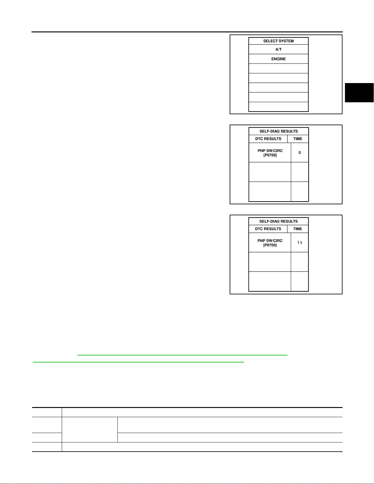
ON BOAR D DIAGNOSTIC SYST EM DESCRIPTION
A sample of C ONS U LT-I I disp lay fo r DTC and 1st tr ip DT C is show n
in the follow ing page. DTC or 1st trip D TC of a malfunction is displayed in “SELF DIAGNOSIS” mode for “ENGINE” with CONSULTII. Time data indica tes how many times th e vehicle w as driv en after
the last detection of a DTC.
If the DTC is being detected currently, the time data will be “0”.
A
B
AT
SAT014K
D
E
F
G
SAT015K
If a 1st trip DTC is stored in the ECM, the time data wi ll be “1t”.
SAT016K
Freeze Frame Data and 1st Trip Freeze Frame Data
The ECM has a memory function, which stores the driving condition such as fuel system status, calculated
load value, en gine coolant temperature, sh ort term fuel trim, long term fuel tr im, engine sp eed and vehicle
speed at the moment the ECM detects a malfunction.
Data which are store d in the ECM memory, along with the 1st trip DTC, are called 1st trip fr eeze frame da ta,
and the data, stored together wit h the DTC data, are called freeze fr ame data and disp layed on CON SULT-II
or GST. The 1st trip freeze fram e data can only be disp layed on the CO NSU LT- II screen , not on the GST. For
detail s, ref er to EC-59, "
EC-678, "
FREEZE FRAME DATA AND 1ST TRIP FREEZE FRAME DATA" (with VQ35DE).
Only one set of fre eze fr ame d ata (e ither 1s t trip f reeze fram e data of fr eeze fr am e data) can be store d in the
ECM. 1st trip fr eeze fram e da ta is stor ed in the ECM mem ory al on g with t he 1st tr ip DT C . There is no priori ty
for 1st trip freeze frame data and it is updated each tim e a differen t 1st trip D TC is de tected. However, once
freeze frame data (2nd trip detection /MIL on) is sto red in the ECM me mory, 1st trip freeze frame d ata is no
longer store d. Re memb er, only one set of freeze fr am e data can be st ored in the EC M. The E C M has th e following priorities to update the data.
Priority Items
1 Freeze fram e data Misfire — DTC: P0300 - P0306
2 Exce pt the above items (Includes A/T rel ate d it em s)
3 1st trip freeze frame data
FREEZE FRAME DATA AND 1ST TRIP FREEZE FRAME DATA" (with QR25DE ) or
Fuel Injection System Function — D TC: P0171, P0172, P0174, P0175
H
I
J
K
L
M
AT-37
Page 56

ON BOAR D DI AGNOSTIC SYSTE M DE SCRIPTION
Both 1st trip freeze frame data and freeze frame data (along with the DTCs) are cleared when the ECM memory is erased .
HOW TO ERASE DTC
The diagnostic trouble code can be erased by CON SULT-II, GST or ECM DIAGNOSTIC T EST MODE as
described following.
● If the battery terminal is disconnected, the diagnostic trouble code will be lost within 24 hours.
● When you erase the DTC, using CONSULT-II or GST is easier and quicker than switching the mode
selector on the ECM.
The following emi ssion-related diagnostic infor mation is cleared from the ECM me mory when erasing DTC
related to OBD-II . For details, refer to EC-55, "
EC-674, "
● Diagnostic trouble codes (DTC)
● 1st trip diagnostic trouble codes (1st trip DTC)
● Freeze frame data
● 1st trip freeze frame data
● System readiness test (SRT) codes
● Test values
Emission-related Di agno stic Infor mation " (with VQ35DE).
HOW TO E RASE DTC (WITH CONSULT-II)
● If a DTC is displayed for both ECM and TCM, it needs to be erased for both ECM and TCM.
1. If the ignition s witch stays ON after repair w ork, be sure to tur n ignition switch OFF on ce. Wait at least 10
seconds and then turn it ON (engine stopped) again.
2. Turn CONSULT-II “ON” and touch “A/T”.
3. Touch “SELF-DIAG R ESULTS”.
4. Touch “ERASE”. (The DTC in the TCM will be erased.) Then touch “BACK” twice.
5. Touch “ENGINE”.
6. Touch “SELF DIAGNOSIS”.
Emission-related D iagnostic Information " (with QR25DE), or
AT-38
Page 57
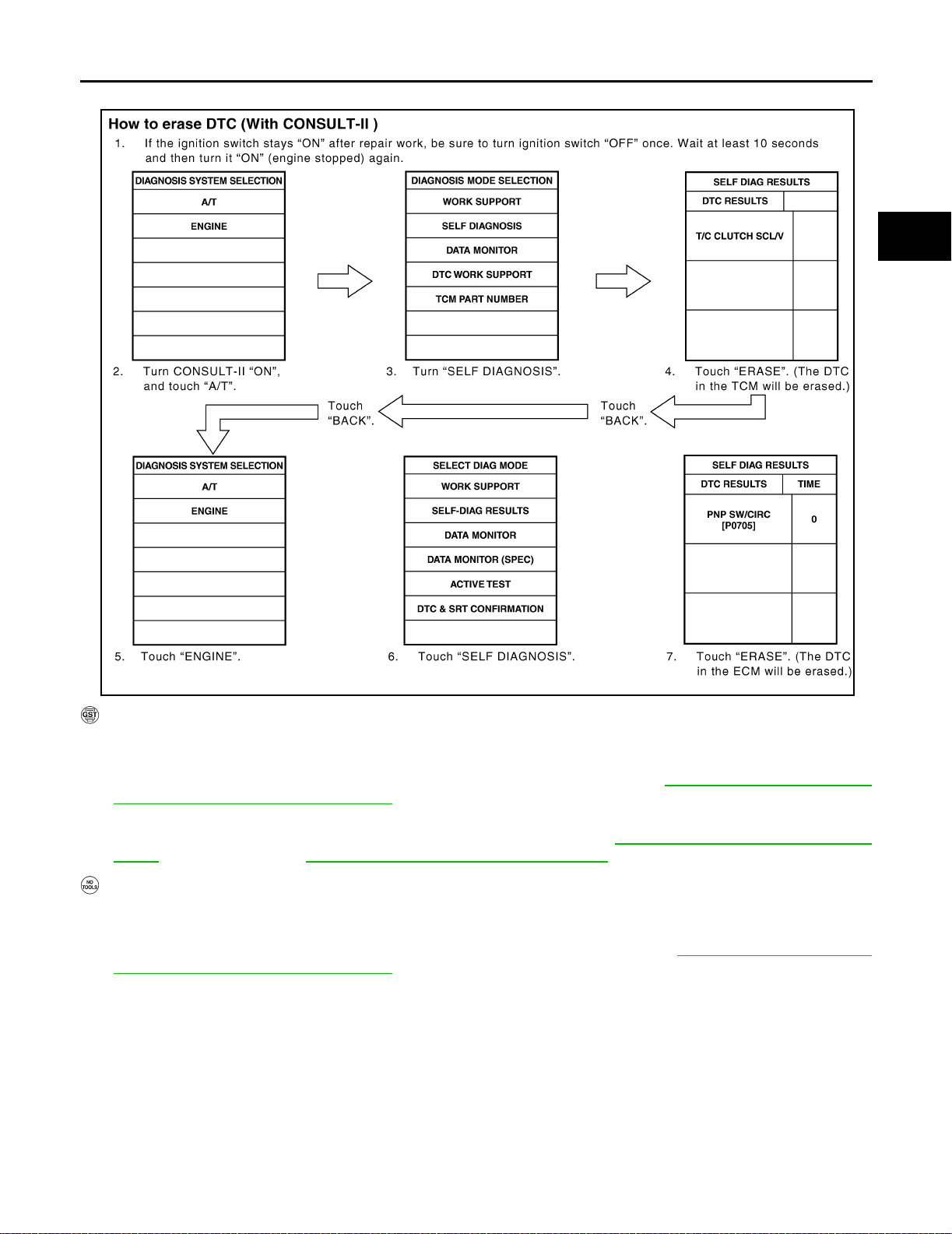
ON BOAR D DIAGNOSTIC SYST EM DESCRIPTION
7. Touch “ERASE”. (The DTC in the ECM will be erased.)
A
B
AT
D
E
F
G
SAT286K
HOW TO ERASE DTC (WI TH GS T)
1. If the ignition switch stays ON afte r repair wor k, be su re to turn igni tion s witch O FF once. Wait at least 10
seconds and then turn it ON (engine stopped) again.
2. Perform “OBD-II SELF-DIAGNOSTIC PROCEDURE (No Tools)”. Refer to AT- 5 0 , "
OBD-II SELF-DIAGNOSTIC PROCEDURE (NO TOOLS)" . (The eng ine warm -up step can be s kipped whe n perfo rming the
diagnosis only to erase the DTC.)
3. Select Mode 4 with Generic Scan Tool (GST). For details, refer to EC-68, "
How to Erase D TC ( With
GST)" (with QR25DE ), or EC- 688, "How to E rase DTC ( With GST)" (with VQ35DE).
HOW TO ERASE DTC (NO TO OLS)
1. If the ignition switch stays ON afte r repair wor k, be su re to turn igni tion s witch O FF once. Wait at least 10
seconds and then turn it ON (engine stopped) again.
2. Perform “TCM SELF-DIAGNOSTIC PROCEDURE (NO TOOLS)”. Refer to AT-51, "
NOSTIC PROCEDURE (NO TOOLS)" . (The eng ine warm -up step can be s kipped whe n perfo rming the
diagnosis only to erase the DTC.)
TCM SELF-DIAG-
H
I
J
K
L
M
AT-39
Page 58
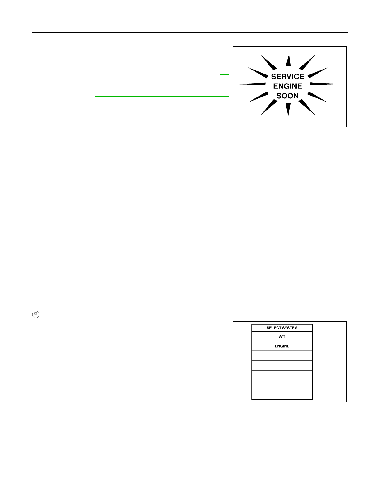
ON BOAR D DI AGNOSTIC SYSTE M DE SCRIPTION
Malfunction Indi cat or Lam p ( MIL)
ECS004R7
1. The malfunction indicator lamp will light up when the ignition
switch is turned ON without the engine running. This is for
checking the lamp.
● If the malfunction indi cator lamp doe s not light up, re fer to DI-
22, "WARN I N G LA M P S" .
[Or see EC-69, "
QR25DE), or EC-689, "
Malfunction Indicator Lamp (MIL)" (with
Malfunction Indicator Lamp (MIL)"
(with VQ35 DE).]
2. When the engine is started, the malfunction indicator lamp
should go off.
If the lamp remains on, the on board diagnostic system has
SAT964I
detected an e mission-related (O BD-II) malfunction . For details,
refer to EC-55, "
Emission-related D iagno stic Informati on" (with Q R25DE ), or EC- 674, "Emission-related
Diagnostic Information" (with VQ35DE).
CONSULT-II ECS004R8
After performing “SELF-DIAGNOSTIC PROCEDURE (WITH CONSULT-II)” (AT-40, "SELF-DIAGNOSTIC
PROCEDURE (WITH C ONSULT-II)" ), place check mar ks for results on the “Diagnost ic Worksheet”, AT-56,
"DIAGNOSTIC WORKSHEET" . Reference pages are provide following the items .
NOTICE:
1. The CONSULT-II electrically displays shift timing and lock-up timing (that is, operation timing of each solenoid).
Check for time difference between actual shift timing and the CONSULT-II display. If the difference is
noticeable, mecha nica l parts (exce pt solenoi ds, s en sors, etc.) may be malfun ct ioning. C hec k mechan ical
parts using applicable diagnostic procedures.
2. Shift sch edule ( which i mplies gear pos ition ) display ed on C ONSU LT-II and that indicated i n Servic e Man ual may differ slightly. This occurs because of the following reason s:
– Actual shift schedule has more or less tolerance or allowance,
– Shift schedule indicated in Service Ma nual refers to the point where shifts start, and
– Gear position displayed on CONSULT-II indicates the point where shifts are completed.
3. Shift sole noid valve “A” or “B” is displayed on CONSULT- II at the start of shifting. Gear position is displayed upon completion of shifting (which is computed by TCM).
4. Additiona l CONSU LT-II info rmation can be found in the Op eration Man ual suppli ed with the CON SULT- II
unit.
SELF-DIAGNOSTIC PROCEDURE (WITH CONSULT-II)
1. Turn on CON SULT-II and touc h “ENGINE” for OBD-II detec ted
items or touch “A/T” for TCM self-diagnosis.
If A/T is not displayed, check TCM power supply and ground circuit. Refer to AT-10 0, "
TROUBLE DIAGNOSIS FOR POWER
SUPPLY" . If result is NG, refer to PG-3, "POWER SUPPLY
ROUTING CIRCUIT" .
AT-40
SAT014K
Page 59
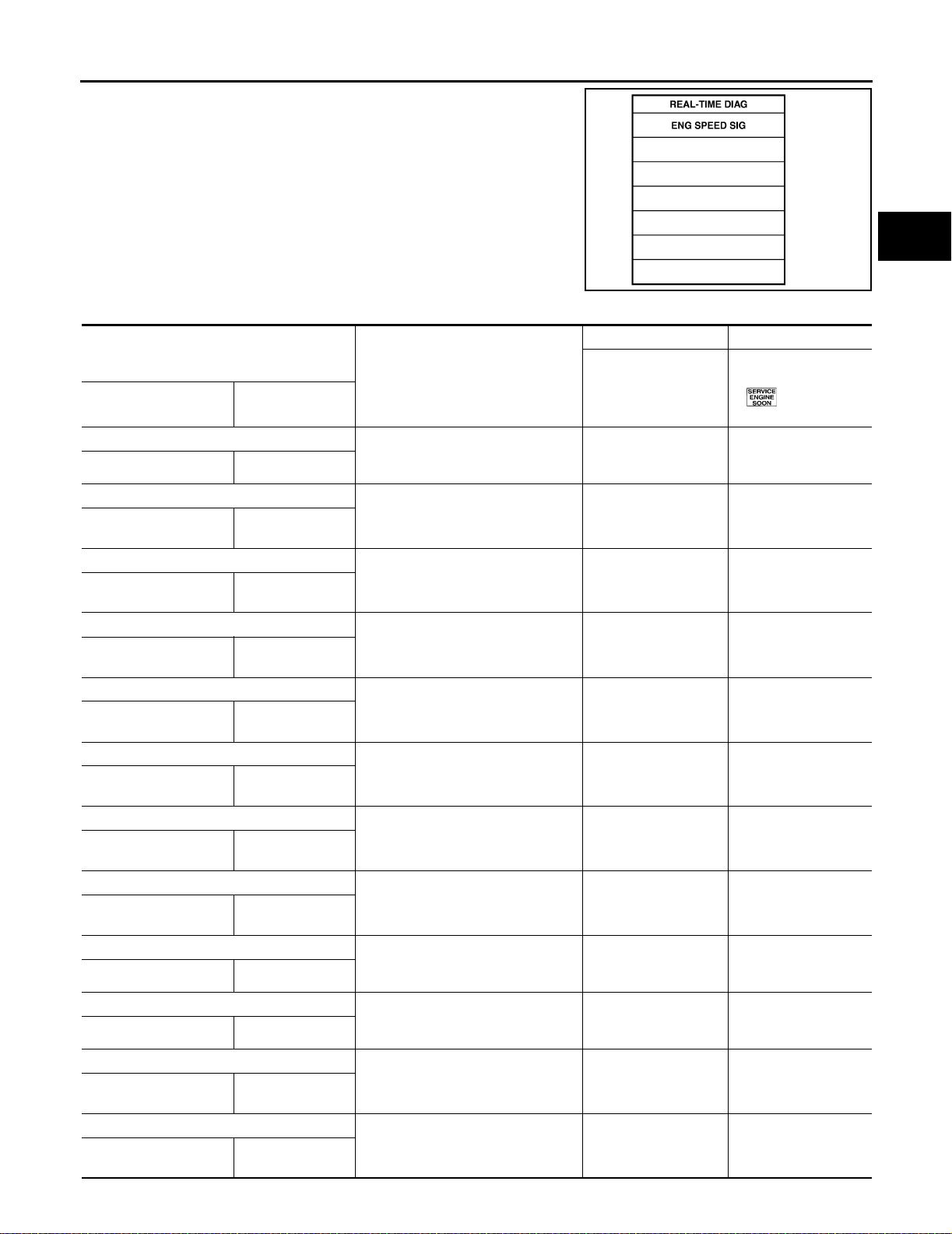
ON BOAR D DIAGNOSTIC SYST EM DESCRIPTION
2. Touch “SELF DIAGNOSIS”.
Display shows malfunction experienced since the last erasing
operation.
CONSULT-II performs “Real Time Diagnosis”.
Also, any malfunction detected while in this mode will be displayed at real time.
SELF-DIAGNOSTIC RESULT TEST MODE
Detected items
(Screen terms for C ONSULT-II, “SELF
DIAGNO SIS” test mode)
“A/T” “ENGINE”
Park/neutral position (PNP) switch circuit
— PNP SW/CIRC
Revolution sensor
VHCL SP EED SEN·A/T
Vehicle speed sensor (Meter )
VHCL SP EED
SEN·MTR
A/T 1st gear fu nc t ion
—
A/T 2nd gear function
—
A/T 3rd gear function
—
A/T 4th gear fu nc t ion
—
A/T TCC S/V function (lock-up)
—
Shift solenoid valve A
SHIFT SOLENO ID/V A SFT SOL A/CIRC
Shift solenoid valve B
SHIFT SOLENO ID/V B SFT SOL B/CIRC
Overrun clutch solenoid valve
OVERR UN CLUTCH S/VO/R CLUCH SOL/
T/C clutch sol e no i d valv e
T/C CLUTCH SOL/V
VEH SPD SEN /
CIR AT
—
A/T 1ST GR
FNCTN
A/T 2ND GR
FNCTN
A/T 3RD GR
FNCTN
A/T 4TH GR
FNCTN
A/T TCC S/V
FNCTN
CIRC
TCC SOLE NO I D/
CIRC
Malfunction is detected when...
● TCM does not receive the correct
voltage signal (based on the gear
positi on) fro m the sw itch.
● TCM does not receive the proper
voltage signal from the sensor.
● TCM does not receive the proper
voltage signal from the sensor.
● A/T cannot be shifted to the 1st
gear position even if electrical circuit is good.
● A/T cannot be shifted to the 2nd
gear position even if electrical circuit is good.
● A/T cannot be shifted to the 3rd
gear position even if electrical circuit is good.
● A/T cannot be shifted to the 4th
gear position even if electrical circuit is good.
● A/T cann ot perf orm lock- up ev en if
electrical circuit is good.
● TCM detects an improper voltage
drop when it tries to operate the
solenoid valve.
● TCM detects an improper voltage
drop when it tries to operate the
solenoid valve.
● TCM detects an improper voltage
drop when it tries to operate the
solenoid valve.
● TCM detects an improper voltage
drop when it tries to operate the
solenoid valve.
TCM self-diagnosis OBD-II (DTC)
Availa ble by A/T c heck
(position) indicator
lamp or “A/T” on
CONSULT-II
— P0705
X P0720
X—
— P0731*1
— P0732*1
— P0733*1
— P0734*1
— P0744*1
X P0750
X P0755
X P1760
X P0740
Available by m alfunc tion indicator lamp*2,
“ENGINE” on
CONSULT-II or GST
A
B
AT
SAT987J
D
E
F
G
H
I
J
K
L
M
AT-41
Page 60
ON BOAR D DI AGNOSTIC SYSTE M DE SCRIPTION
Detected items
(Screen terms for CONSULT-II, “SELF
DIAGNOSIS” test mode)
“A/T” “ENGINE”
Line pressure solenoid valve
LINE PR ESSURE S/V
L/PRESS SOL/
CIRC
Throttle position sensor [accelerator pedal
position (APP) sensor]
THROTTLE POSI SEN TP/SEN/CI RC A/T
Engine speed signal
ENGINE SPEED SIG
A/T fluid temperature sensor
BAT T/FLUID TEMP
SEN
ATF TEMP SEN/
CIRC
Engine contr ol
A/T COMM L INE —
Turbine revolution sensor
TURBINE REV
Malfunction is de tected when...
● TCM detects an improper voltage
drop when it tries to operate the
solenoid valve.
● TCM receives an excessively low
or high voltage from this sensor
● TCM does not receive the proper
voltage signal from the ECM.
● TCM receives an excessively low
or high voltage from the sensor.
● The ECM-A/T communication line
is open or shorted.
● TCM does not receive proper volt-
age signal f rom sens or
TCM self-diagnosis OBD-II (DTC)
Avail able b y A/T che ck
(position) indicator
lamp or “A/T” on
CONSULT-II
Availa bl e by ma lf un c-
tion indicator la mp*2,
“ENGINE” on
CONSULT-II or GST
X P0745
X P1705
X P0725
X P0710
X U1000
X—
TCM (RAM)
CONTROL UNIT
(RAM)
TCM (ROM)
CONTROL UNIT
(ROM)
TCM (EEP ROM)
CONT UNIT(EEP
ROM)
Initial start
INITIAL START —
—
—
—
● TCM memory ( RAM) is malfunc-
tioning
● TCM memory ( ROM) is malfun c-
tioning
● TCM memory ( EEP ROM) is mal-
functioning.
● This is no t a m al f un cti o n m essage
(Whenever shutting off a power
supply to the TCM, this m essage
appears on the screen.)
——
——
——
X—
No failure
(NO SELF DIAGNOSTIC FAILURE INDICATED FURTHER TESTING MAY BE
● No fai lure has been detected. X X
REQUIRED**)
X: Applicable
−: Not applicable
*1: These malfunctions cannot be displayed by MIL if another malfunction is assigned to MIL.
*2: Refer to EC-69, "Malfunction Indicator Lamp (MIL)" (with QR25DE), or EC-689, "Malfunction Indicator Lamp (MIL)" (with VQ35D E) .
AT-42
Page 61
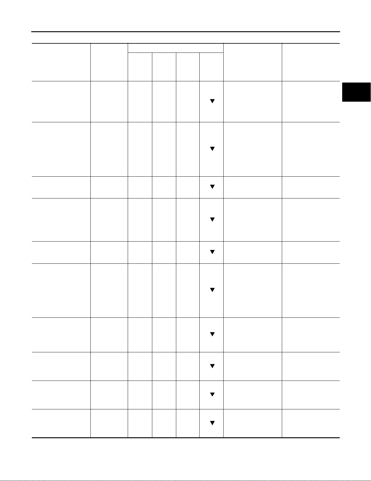
ON BOAR D DIAGNOSTIC SYST EM DESCRIPTION
DATA MONITOR MODE (A/T)
Item Display
Ve hicl e spee d sen sor 1
(A/T)
(Revolution sensor)
Vehicle speed sensor 2
(Meter)
Throttle position sensor
[accelerator pedal position (APP) sensor]
A/T fluid temperature
sensor
Battery voltage BATTERY
Engine speed ENGINE
Turbine revolution sensor
Overdrive control
switch
PN position (PNP)
switch
R position switch R POSITION
VHCL/S
SE·A/T
[km/h] or
[mph]
VHCL/S
SE·MTR
[km/h] or
[mph]
THRTL POS
SEN [V]
FLUID TEMP
SE
[V]
VOLT
[V]
SPEED
[rpm]
TURBINE
REV
OVERDRIVE
SW
[ON/OFF]
PN POSI SW
[ON/OFF]
SW
[ON/OFF]
Monitor item
TCM
Input
signals
CAN
Comm.
signals
Main
signals
X——
X——
X——
X——
X——
X—X
X——
X——
X——
X——
Selec-
tion
from
menu
Description Remarks
● Vehi c l e spe ed com -
● When racing engine
puted from signal of
revolution sensor is
displayed.
● Vehi c l e spe ed com -
● Vehi c l e spe ed dis-
puted from signal of
vehicle sp eed sensor
is displayed.
● Throttle position sen-
sor signal voltage is
displayed
● A/T flui d temper ature
sensor sig nal voltage
is displayed.
● Signal vo ltage low ers
as fluid temperature
rises.
● Source volt age of
TCM is displayed.
● Engine speed, com-
● Engine sp eed dis-
puted from engine
speed signal, is displayed.
● Checks changing
speed th en performs
oil pressure control
and torque down
control
● ON/OFF state com-
puted from signal of
3 position switch is
displayed.
● ON/OFF state com-
puted from signal of
PN position SW is
displayed.
● ON/OFF state com-
puted from signal of
R position SW is displayed.
in N or P wi th ve hic le
stationary, CONSULT-II da ta may
not indicate 0 km/h
(0 mph).
play m ay not be
accurate under
approx. 10 km /h ( 6
mph). It may not
indicate 0 km/h (0
mph) when vehic le is
stationary.
play m ay not be
accurate under
approx. 800 rp m. It
may not indicate 0
rpm even when
engine is not running.
A
B
AT
D
E
F
G
H
I
J
K
L
M
AT-43
Page 62
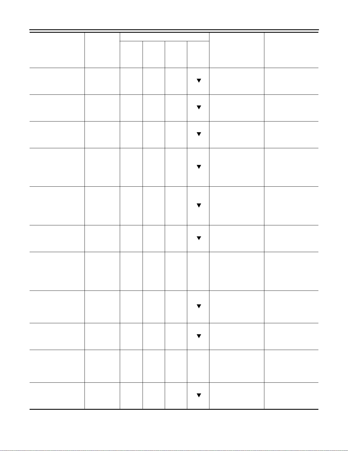
ON BOAR D DI AGNOSTIC SYSTE M DE SCRIPTION
Item Display
D position switch D POSITION
SW
[ON/OFF]
2 positio n swit c h 2 POSITION
SW
[ON/OFF]
1 positio n swit c h 1 POSITION
SW
[ON/OFF]
ASCD cruise signal ASCD·CRUIS
E
[ON/OFF]
ASCD OD cut signal ASCD·OD
CUT
[ON/OFF]
Kickdown switch KICKDOWN
SW
[ON/OFF]
Stop lamp switch BRAKE SW
[ON/OFF]
Selector lever position SLCT LVR
POSI
V ehicle speed VEHICL E
SPEED
[km/h] or
[mph]
Throttl e pos i tion
[Accelerator pedal
position (APP) sensor]
Gear position GEAR
THROTTLE
POSI
[/8] — — X —
Monitor it em
TCM
Input
signals
CAN
Comm.
signals
Main
signals
Selec-
tion
from
menu
X——
X——
X——
X——
X——
X——
X———
——X
——X
——X
Description Remarks
● ON/OFF state com-
puted from signal of
D position SW is displayed.
● ON/OFF status,
comput ed from si gnal of 2 position SW,
is displayed.
● ON/OFF status,
comput ed from si gnal of 1 position SW,
is displayed.
● Sta tus of ASC D
cruise signal is displayed.
ON ... Cruising state
OFF ... Normal running state
● Sta tus of ASC D OD
release signal is displayed.
ON ... OD released
OFF ... OD not
released
● ON/OFF status,
● This is displayed
comput ed from si gnal of ki ckdow n SW,
is displayed.
● ON/O FF status is
displayed.
ON ... B rake pedal is
depressed.
OFF ... Brake pedal
is released.
● Selector lever posi-
● A specific value
tion dat a, used f or
computation by
TCM, is displayed.
● Vehicle speed data,
used for computation by TCM, is di splayed.
● Throttle position
● A specific value
data, used for computatio n by TC M , is
displayed.
● Gear position data
used for computation by TCM, is di splayed.
even when no kickdown switch is
equipped.
used for control is
displayed if fail-safe
is activated due to
error.
used for control is
displayed if fail-safe
is activated due to
error.
AT-44
Page 63
ON BOAR D DIAGNOSTIC SYST EM DESCRIPTION
Monitor item
Item Display
TCM
Input
signals
CAN
Comm.
signals
Main
signals
Line pressure duty LINE PRES
DTY
[%] — — X —
T orque con verter clutch
solenoid valve duty
TCC S/V
DUTY
[%]
——X—
Shift solenoid valve A S HIFT S/V A
[ON/OFF]
——X—
Shift solenoid valve B S HIFT S/V B
[ON/OFF]
——X—
Overrun clu tch solenoid valve
Self-diagnosis display
lamp [A/T check (position) indicator lamp]
Torque converter slip
ratio
Torque converter slip
speed
OVERRUN/C
S/V
[ON/OFF]
SELF-D DP
LMP
[ON/OFF]
TC SLIP
RATIO [0.000]
TC SLIP
SPEED [rpm]
——X
——X
———
———
Voltage [V] — — —
Frequency [Hz] — — —
Selec-
tion
from
menu
Description Remarks
● Control value of line
pressure solenoid
valve, comp uted by
TCM fro m eac h inpu t
signal, is displayed.
● Control value of
torque converter
clutch solenoid
valve, comp uted by
TCM fro m eac h inpu t
signal, is displayed.
● Control value of shift
● Control value of
solenoid valve A,
computed by TCM
from each input signal, is disp layed.
● Control value of shift
solenoid valve B,
computed by TCM
from each input signal, is disp layed.
● Control value of
overrun clut ch solenoid valve computed
by TCM from each
input signal is displayed.
● Control status of A/T
check (position) indicator lamp is displayed.
● Ratio of engine revo-
lution to input shaft
revolution of torque
converter.
● Difference in revo lu-
● Display doe s not
tion between input
shaft revolution and
torque converter
input shaft revolution.
● Value measured by
voltage probe is displayed.
● Value measured by
pulse probe is displayed. If measurement is impossible,
"#" sign is displaye d.
"#" sign is also dis played at the final
data value until th e
measur eme nt result
is obtained.
solenoid is displayed
even if solenoid circuit is disconnected.
The OFF signal is
displayed if solenoid
circuit is shorted .
indicate engine is
stopped even if 0
rpm — this is not a
malfunction.
A
B
AT
D
E
F
G
H
I
J
K
L
M
AT-45
Page 64

ON BOAR D DI AGNOSTIC SYSTE M DE SCRIPTION
Monitor it em
Item Display
DUTY-HI — — —
DUTY-LOW — — —
PLS WIDTH-HI — — —
PLS WIDTH-LOW — — —
CAN communication
CAN circuit 1
CAN circuit 2
CAN circuit 3
CAN circuit 4
CAN circuit 5
X: Applicable
—: Not applicable
: Option
CAN COMM
[OK/UNKWN]
CAN CIRC 1
[OK/UNKWN]
CAN CIRC 2
[OK/UNKWN]
CAN CIRC 3
[OK/UNKWN]
CAN CIRC 4
[OK/UNKWN]
CAN CIRC 5
[OK/UNKWN]
TCM
Input
signals
—X—
—X—
—X—
—X—
—X—
—X—
CAN
Comm.
signals
Main
signals
Selec-
tion
from
menu
Description Remarks
● Duty cycle value for
measurement probe
is displayed.
● Measured pul se
width of measurement probe is displayed.
DTC WORK SUPPORT MODE WITH CONSULT-II
CONSULT-II Setting Procedur e
1. Turn ignition switch OFF.
2. Connec t CO NSU LT-II to Data link c onn ector, which is located in
left side dash panel.
3. Turn ignition switch ON.
4. Touch “START”.
LCIA0042E
AT-46
SAT586J
Page 65
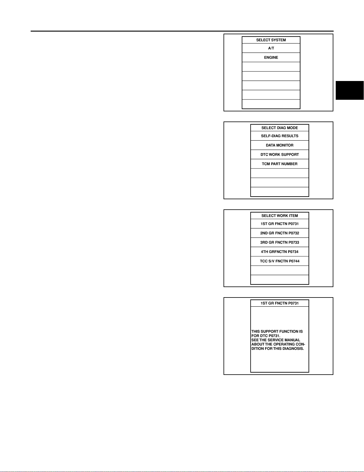
ON BOAR D DIAGNOSTIC SYST EM DESCRIPTION
5. Touch “A/T ”.
6. Touch “DTC WORK SUPPORT”.
A
B
AT
SAT014K
D
E
F
G
SAT971J
7. Touch select item menu (1ST, 2ND, etc.).
8. Touch “START”.
SAT018K
SAT589J
H
I
J
K
L
M
AT-47
Page 66
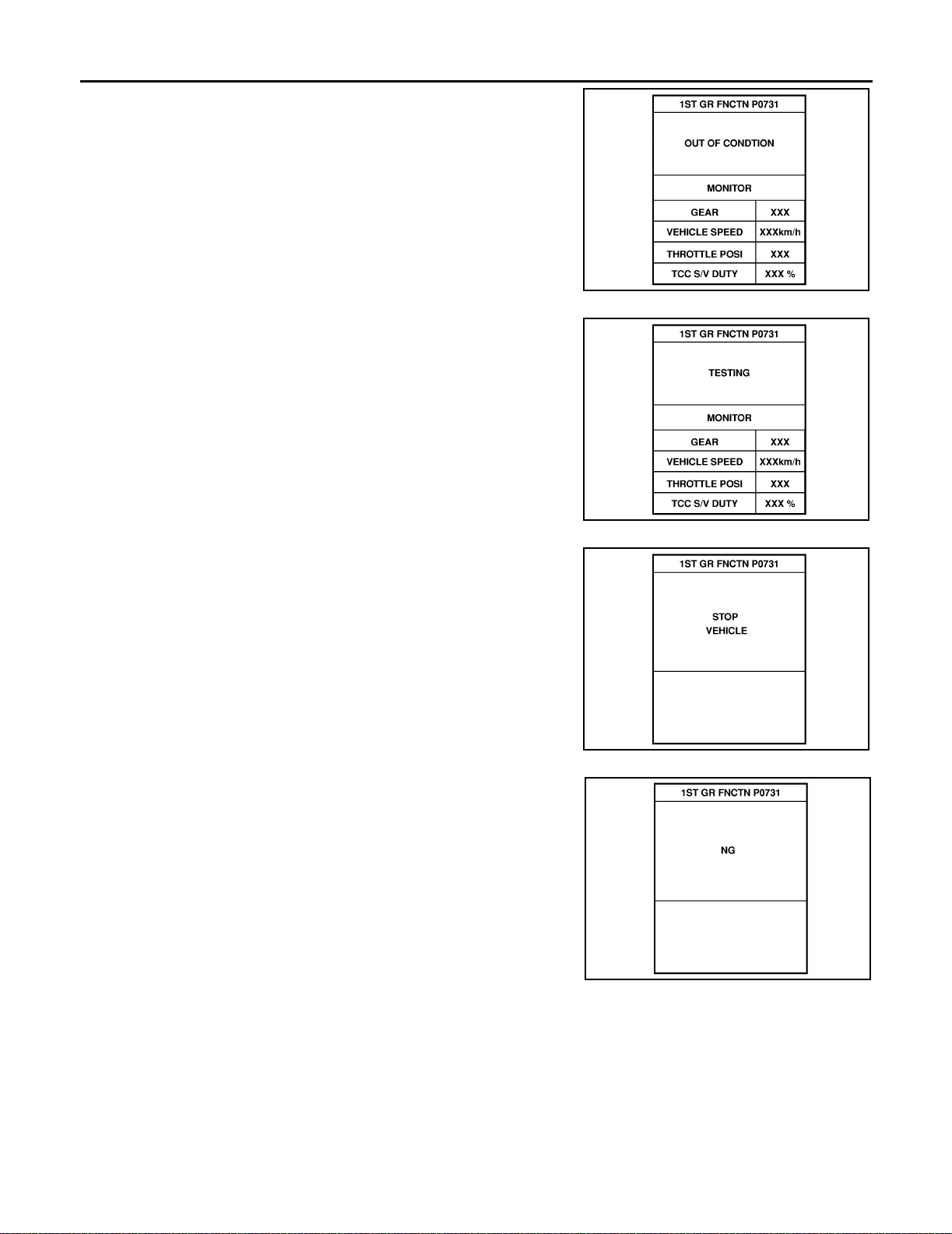
ON BOAR D DI AGNOSTIC SYSTE M DE SCRIPTION
9. Perfor m driving tes t according to “DTC C ONFIRMATION PROCEDURE” in “TROUBLE DIAGNOSIS FOR DTC”.
● When testing conditions are satisfied, CONSULT-II screen
changes fro m “OUT O F CONDITION” to “TESTING”.
SAT019K
10. Stop vehicle. If “NG” appears on the screen, malfunction may
exist. Go to “DIAGNOSTIC PROCEDURE”.
SAT591J
SAT592J
AT-48
SAT593J
Page 67
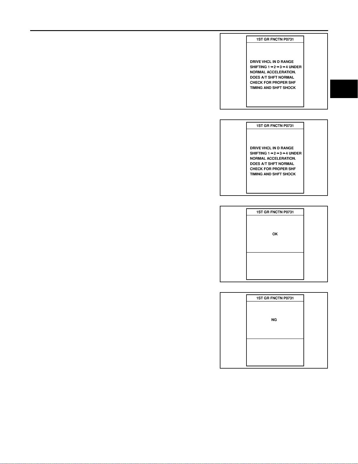
ON BOAR D DIAGNOSTIC SYST EM DESCRIPTION
11. Perform t est dr ive to chec k ge ar shift feel ing in ac cord ance w ith
instructions displayed.
12. Touch “YES” or “NO”.
A
B
AT
SAT594J
D
E
F
G
SAT595J
13. CONSULT-II procedure ended.
If “NG” appears on the screen, a malfunction may exist. Go to “DIAGNOSTIC PROCEDURE”.
SAT596J
SAT593J
H
I
J
K
L
M
AT-49
Page 68

ON BOAR D DI AGNOSTIC SYSTE M DE SCRIPTION
DTC WORK SUP PO RT M ODE
DTC work support item Descript ion Check item
1ST GR FNCTN P0731
2ND GR FN CTN P0732
3RD GR FN CTN P0733
4TH GR FN CTN P0734
TCC S/V FNCTN P0744
Following items for “A/T 1st gear function (P0731)” can be confirmed.
● Self-dia gn osis status (whether the diagnosis is being c on duc t ed
or not)
● Self-diagnosis result (OK or NG)
Following items for “A/T 2nd gear function (P0732)” can be confirmed.
● Self-dia gn osis status (whether the diagnosis is being c on duc t ed
or not)
● Self-diagnosis result (OK or NG)
Following items for “A/T 3rd gear function (P0733)” can be confirmed.
● Self-dia gn osis status (whether the diagnosis is being c on duc t ed
or not)
● Self-diagnosis result (OK or NG)
Following items for “A/T 4th gear function (P0734)” can be confirmed.
● Self-dia gn osis status (whether the diagnosis is being c on duc t ed
or not)
● Self-diagnosis result (OK or NG)
Following items for “A/T TCC S/V function (lock-up) (P0744)” can
be confirmed.
● Self-dia gn osis status (whether the diagnosis is being c on duc t ed
or not)
● Self-diagnosis result (OK or NG)
● Shift solenoid valve A
● Shift solenoid valve B
● Each clutch
● Hydraulic control circuit
● Shift solenoid valve B
● Each clutch
● Hydraulic control circuit
● Shift solenoid valve A
● Each clutch
● Hydraulic control circuit
● Shift solenoid valve A
● Shift solenoid valve B
● Overrun clutch solenoid valve
● Line pressu re sol e noid valve
● Each clutch
● Hydraulic control circuit
● Torque converter clut ch sol e -
noid valve
● Each clutch
● Hydraulic control circuit
Diagnostic Procedure Without CONSULT-II ECS004R9
OBD-II SELF-DIAGNOSTIC PROCEDURE (WITH GST)
Refer to EC-119, "Generic Scan Tool (GS T) F unction" (with QR25DE), or EC-743, "Gener ic Scan Tool (GST)
Function" (with VQ35DE).
OBD-II SELF-DIAGNOSTIC PROCEDURE (NO TOOLS)
Refer to EC-69, "Malfunction In dica tor L amp ( MIL) " (w ith QR25 DE), or EC-689, "Malfuncti on Indicator La mp
(MIL)" (with VQ35DE).
AT-50
Page 69
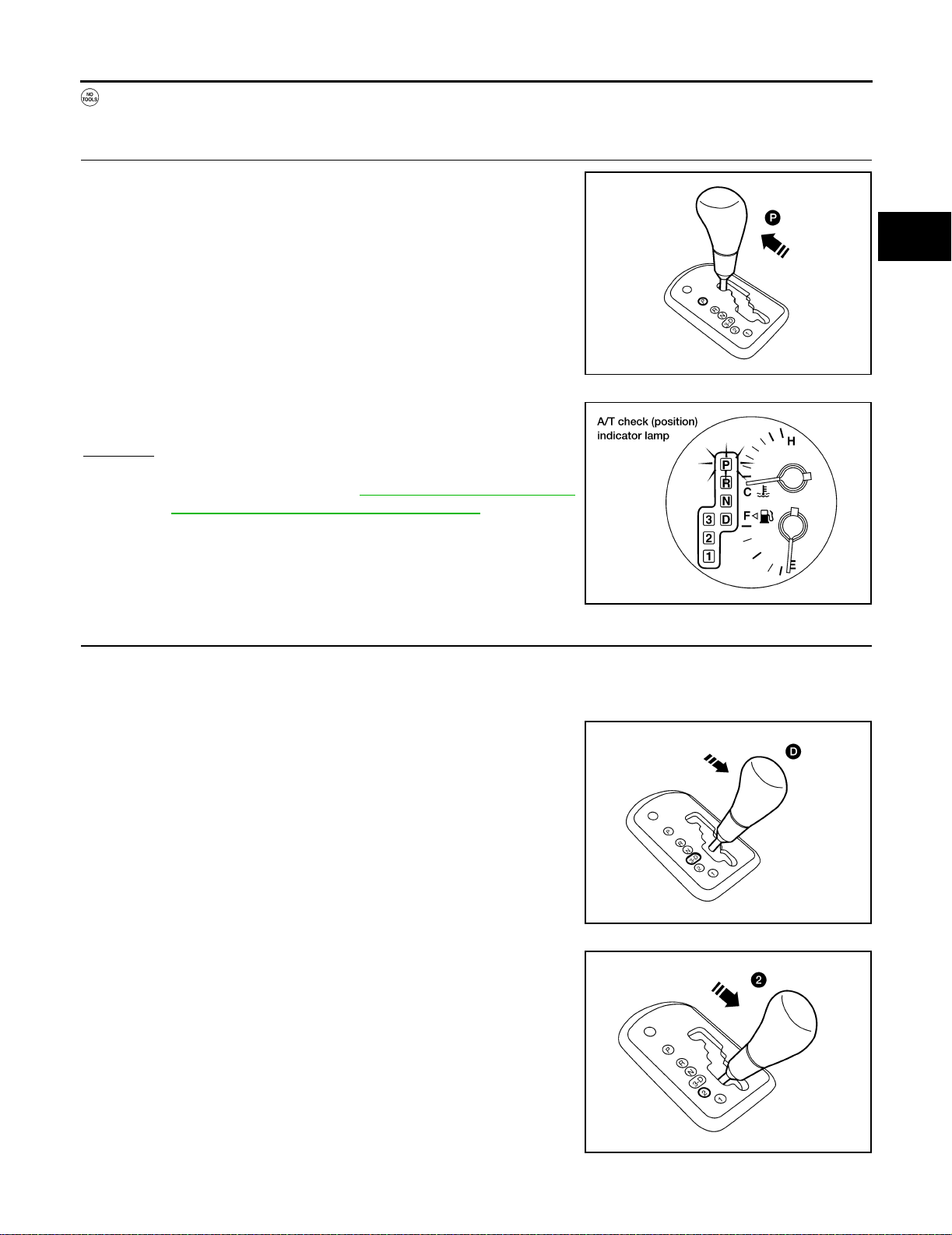
ON BOAR D DIAGNOSTIC SYST EM DESCRIPTION
TCM SELF-DIAGNOSTIC PROCEDURE (NO TOOLS)
1. CHECK A/T CHECK ( POSITION) INDICATOR LAMP
A
1. Move selector lever to P position.
Start engine and warm it up to normal e ngine o per ating tempe rature.
2. Turn ignition switch to OFF position.
3. Wait 5 seconds.
4. Turn ignition switch to ON position.
(Do not start engine.)
5. Does A/T c heck (position) indicato r lamp come on for ab out 2
seconds?
Yes or No
Yes >> GO TO 2.
No >> Stop procedure. Perform AT-213, "
1. A/T Check (Position) Indicator Lamp Do es Not Come On" before pro-
ceeding.
2. JUDGEMENT PROCEDURE STEP 1
LCIA0043E
LCIA0044E
B
AT
D
E
F
G
H
I
1. Turn ignition switch to OFF position.
2. Turn ignition switch to ON position.
(Do not start engine.)
3. Depress the b rake peda l, then move gear selector le ver from P
to D position.
4. Wait 3 seconds.
5. Move selector lever to 2 position.
6. Release brake pedal.
>> GO TO 3.
J
K
L
M
LCIA0045E
AT-51
LCIA0046E
Page 70
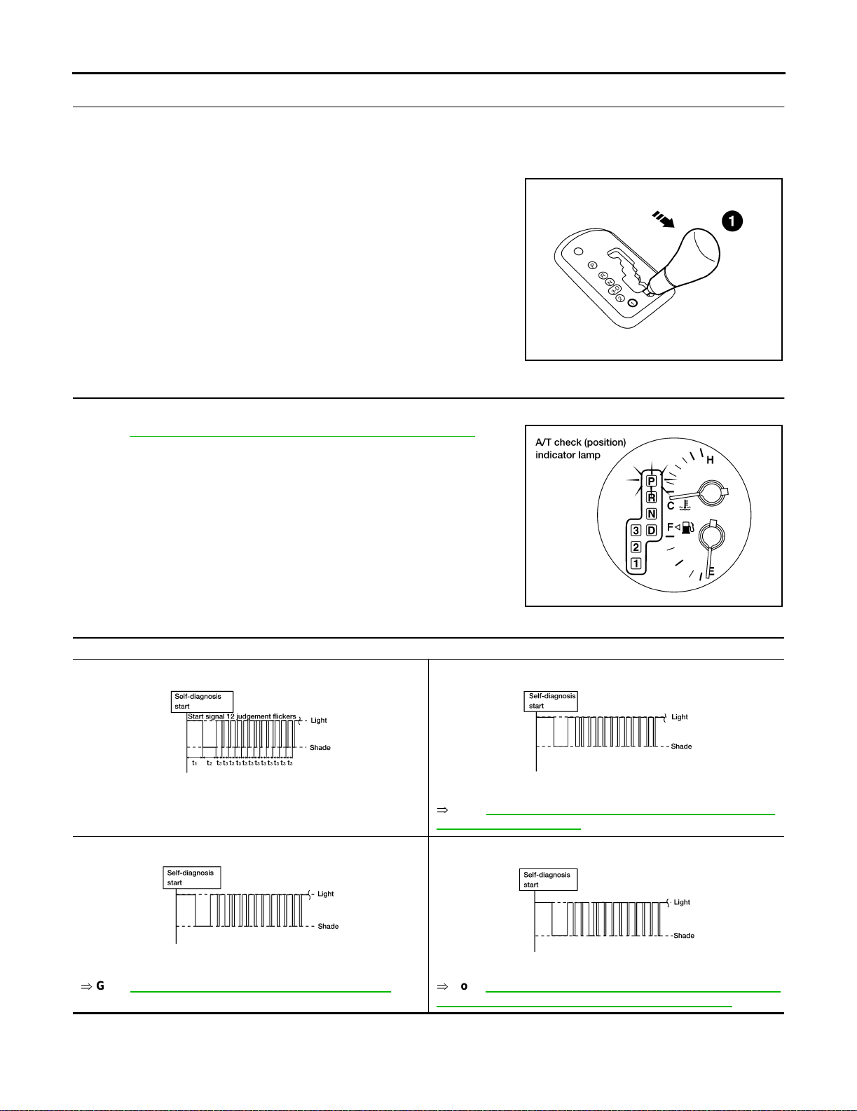
ON BOAR D DI AGNOSTIC SYSTE M DE SCRIPTION
3. JUDGEMENT PROCEDURE STEP 2
1. Move selector lever to 1 position.
2. Depress brake pedal.
3. Depress accelerator pedal fully and release it.
4. The A/T check (position) indicator lamp will begin to flash.
>> GO TO 4.
4. CHECK SE LF- DIA GNO ST IC CO DE
Check A/T check (position) indicator lamp.
Refer to AT-52, "
JUDGEMENT OF SELF-DIAGNOSIS CODE" .
LCIA0047E
>> DIAGNOSIS END
JUDGEMENT OF SELF-DIAGNOSIS CODE
A/T check (position) indicator lamp:
All judgement flickers are the same.
LCIA0049E LCIA0050E
All circuits that can be confirmed by self-diagnosis are OK.
2nd judgement flic ker is l onger than ot hers.
LCIA0044E
1st judgement flicker is longer than others.
Revolution sensor circuit is short-circuited or disconnected.
Þ
Go to AT-115, "DTC P0720 VEHICLE SPEED SENSOR·A/T
(REVOLUTION SENSOR)" .
3rd judgement flicker is longer than others.
LCIA0051E LCIA0052E
Vehicle speed sensor circuit is short-circuited or disconnected.
Þ
Go to AT-196, "DTC VEHI CLE SPEED SENSOR MTR" .
Throttle position sensor circuit is short-circuited or disconnected.
Þ
Go to AT-175, "DTC P1705 THROTTLE POSITION SENSOR
[ACCELERATOR PEDAL POSITION (APP) SENSOR]".
AT-52
Page 71
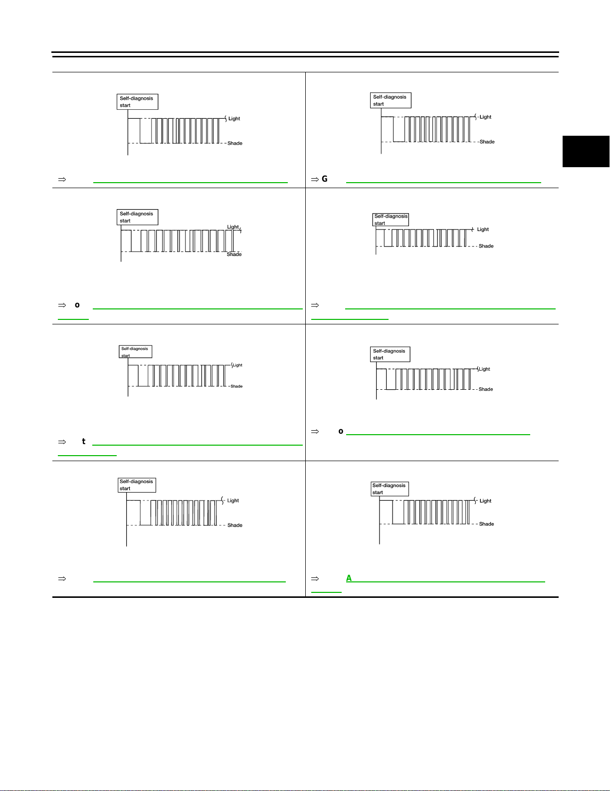
ON BOAR D DIAGNOSTIC SYST EM DESCRIPTION
A/T check (po siti o n) indicator lamp:
4th judgement flicker is longer than others.
LCIA0053E LCIA0054E
Shift solenoid valve A circuit is short-circuited or disconnected.
Þ
Go to AT-165, "DTC P0750 SHIFT SOLENO ID VALVE A" .
6th judgement flicker is longer than others.
LCIA0055E LCIA0056E
Overrun clutch solenoid valve circuit is short-circuited or disconnected.
Þ
Go to AT-180, "DTC P1760 OVE RRUN CLUTCH SOL EN OI D
VALVE" .
8th judgement flicker is longer than others.
5th judgement flicker is longer than others.
Shift solenoid valve B circuit is short-circuited or disconnected.
Þ
Go to AT-170, "DTC P0755 SHIFT SOLENOID VALVE B" .
7th judgement flicker is longer than others.
Torque converter clutch solenoid valve circuit is short-circuited or
disconnected.
Þ
Go to AT-146, "DTC P0740 TORQUE CONVERTER CLUTCH
SOLENOID VALVE" .
9th judgement flicker is longer than others.
A
B
AT
D
E
F
G
H
LCIA0057E LCIA0058E
A/T fluid temperature sensor is disconnected or TCM power
source circuit is damaged.
Þ
Go to AT-109, "DTC P0710 A/T FLUID TEMPERATURE SEN-
SOR CIRCUIT" .
10th judgement flic k er is longer than others.
LCIA0059E LCIA0060E
Turbine revolution sensor circuit is short-circuited or disconnected.
Þ
Go to AT-200, "DTC TURB INE REVOLUTIO N SENSOR " .
Engine speed signal circuit is short-circuited or disconnected.
Þ
Go to AT-120, "DTC P0725 ENGINE SPEED SIGNAL" .
11th judgement flicker is longer than others.
Line pressure solenoid valve circuit is short-circuited or disconnected.
Þ
Go to AT-159, "DTC P0745 LINE PRES SU RE SO LENOID
VALVE" .
I
J
K
L
M
AT-53
Page 72
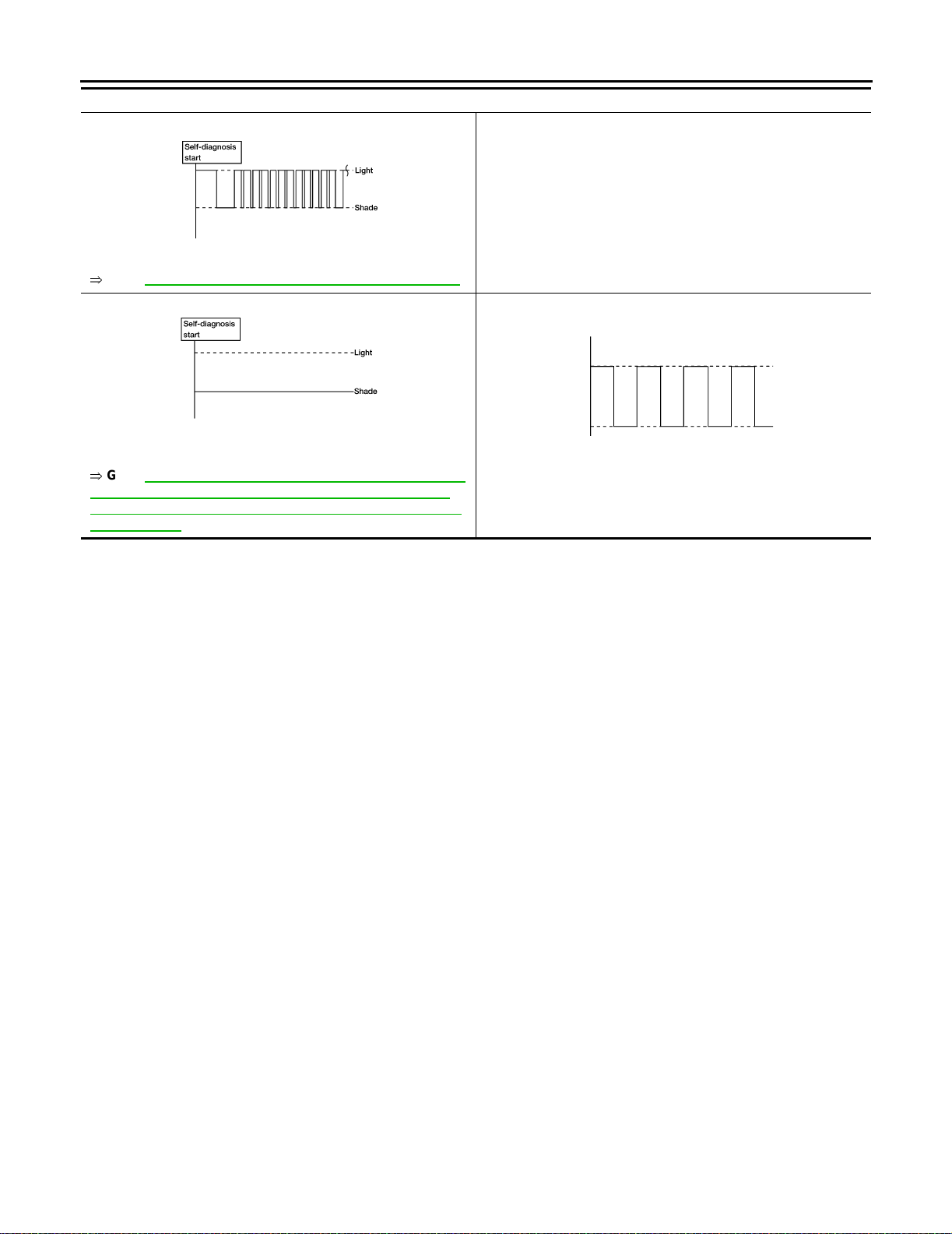
ON BOAR D DI AGNOSTIC SYSTE M DE SCRIPTION
A/T check (position) indicator lamp:
12th judgem ent flicker is longer than other s.
LCIA0061E
The ECM-A/T communication line is open or shorted.
Þ
Go to AT-185, "DTC U1000 CAN CO MMUNICATION LINE" .
Lamp turns off.
LCIA0062E LCIA0063E
Park/ne ut r al p osition (PNP) switch, and 3 position s witch circuit is
disconn ected or TCM is damaged.
Þ
Go to AT-242, "21. TCM Self-diagnosis Does Not Activate
(PNP & 3 Position Switches Circuit Checks), and Throttle
Positi on Sensor [Accelerator Peda l Position (APP) Sens or]
Circuit C heck" .
t1 = 2.5 seconds t2 = 2.0 seconds t3 = 1.0 second t4 = 1.0 second
Flickers as shown belo w.
Battery pow er is l ow.
Battery has been disconnected for a long time.
Battery i s conn ected conversely.
(When reconnecting TCM connectors. — This is not a problem.)
AT-54
Page 73
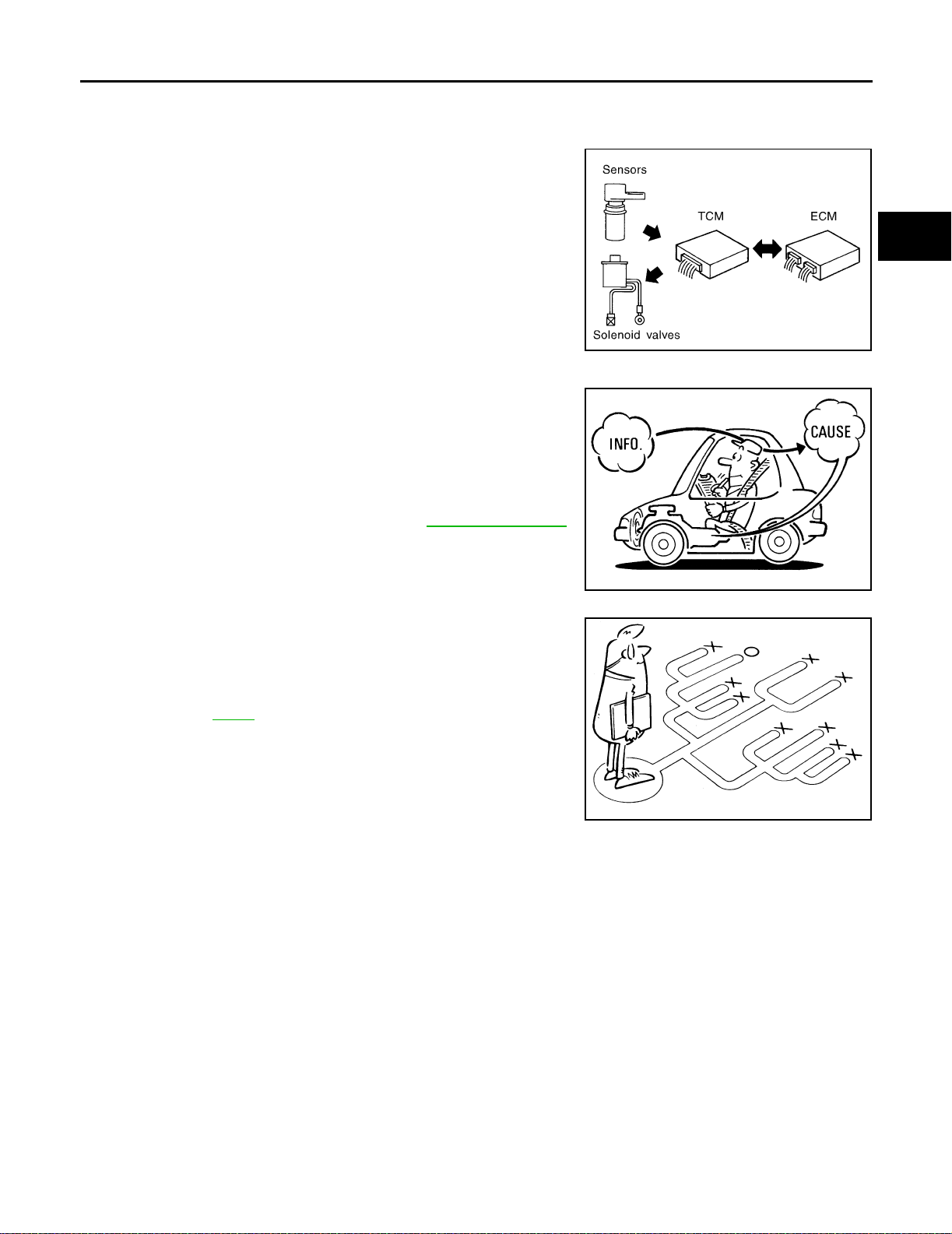
TROUBLE DIAGNOSIS - INTRODUCTION
TROUBLE DIAGNOSIS - INTRODUCTION PFP:00000
Introduction ECS004RA
The TCM receives a signal from the vehicle speed sensor, ECM
(throttle openi ng) or park/neu tral po sition (PN P) switch a nd pr ovid es
shift control or lock-up control via A/T solenoid valves.
The TCM also communicates with the ECM by means of a signal
sent from sensing elem ents used with the OBD-re lated parts of the
A/T system for mal function-diagnostic purpos es. The TCM is capable of diagnosing mal funct ioning parts while the EC M ca n store malfunctions in its memory.
Input and output signals must always be correct and stable in the
operation of the A/T system. The A/ T system must be in good ope rating condition a nd be fre e of valv e sei zure, solen oi d valve malfunc tion, etc.
It is much m ore difficult to dia gnose a problem that occurs inte rmittently rather than continuously. Most intermittent problems are
caused by poor electric connec tions or improp er wiri ng. In this ca se,
careful checki ng of suspec ted circ uits may he lp preve nt the r eplacement of good parts.
A visual check on ly, may not find the cause of the problems. A road
test with C ONSULT- II (or GST ) or a circu it tester co nnected sho uld
be performed. Follow the “Work Flow”. Refer to AT- 59, "
Work Flow" .
SAT631IA
A
B
AT
D
E
F
G
Before und ertaking actual chec ks, take a few minutes to talk with a
customer who approaches with a driveability complaint. The customer can sup ply good information a bout su ch problems, e specially
intermittent ones. Find out what sym ptoms are present and u nder
what conditions they occur. A “DIAGNOSTIC WORKSHEET” like the
example on page AT-57
should be used.
Start your diagnosis by looking for “conventional” problems first. This
will help troubleshoot driv eability problems on an elect ronically controlled engine vehicle.
Also check related Service bulletins for information.
H
SAT632I
I
J
K
L
SEF234G
M
AT-55
Page 74
TROUBL E DIAGNOSI S - INTRODU CTION
DIAGNOSTIC WORKSHEET
Information from Customer
KEY POINTS
WHAT ........ Vehicle & A/T model
WHEN ........ Date, Frequencies
WHERE ..... Road conditions
HOW .......... Operating conditions, Symptoms
Custom er nam e MR/MS Model & Ye ar VIN
Trans. model Engine Mileage
Incident Date Manuf. Date In Service Date
Frequency ❏ Continuous ❏ Intermittent ( times a day)
Symptoms ❏ Vehicle does not move. (❏ Any position ❏ Particular positi on)
❏ No up-shift (❏ 1st → 2nd ❏ 2nd → 3rd ❏ 3rd → 4th)
❏ No down-shift (❏ 4th → 3rd ❏ 3rd → 2nd ❏ 2nd → 1st)
❏ Lockup malfunction
❏ Shift point too high or too low.
❏ Shift shock or slip (❏ N → D ❏ Lockup ❏ Any drive position)
❏ Noise or vibration
❏ No kickdown
❏ No patt ern select
❏ Others
()
A/T check (position) indicator lamp Blinks for about 8 seconds.
❏ Continuously lit ❏ Not lit
Malfunction indicator lamp (MIL) ❏ Continuously lit ❏ Not lit
AT-56
Page 75
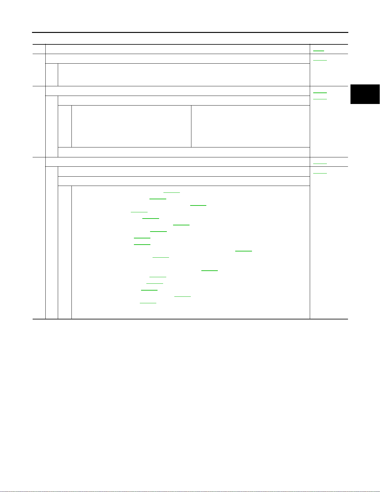
TROUBLE DIAGNOSIS - INTRODUCTION
Diagnostic Worksheet
1. ❏ Read the Fail-safe and listen to customer complaints. AT-9
2. ❏ CHECK A/T FLUID AT-61
❏ Leakage (Fol low specified procedure)
❏ Fluid condition
❏ Fluid level
3. ❏ Perform STALL TEST and PRESSURE TEST. AT-61
❏ Stall test — Mark possible damaged components/others.
❏ Torque converter one-way clutch
❏ Reverse clutch
❏ Forward clutch
❏ Overrun clutch
❏ Forward one-way clutch
❏ Pressure te st — Sus pected parts:
4. ❏ Perform all ROAD TEST and mark required procedures. AT-66
4-1.Check before engine is started. AT-68
❏ SELF-DIAGNOSTIC PROCEDURE - Mark detected items.
❏ Park/neutral position (PNP) switch, AT-103
❏ A/T fluid temperature sensor, AT-109
❏ Vehicle speed sensor·A/T (Revolution sensor), AT-115
❏ Engine speed signal, AT-120
❏ Turbine revolution sensor, AT-200
❏ Torque converter clutch solenoid valve, AT-146
❏ Line pressure solenoi d valve, AT-159
❏ Shift solenoid valve A, AT-165
❏ Shift solenoid valve B, AT-170
❏ Throttle position sensor [accelerator pedal position (APP) sensor], AT-175
❏ Overrun clutch solenoid valve, AT-180
❏ Park/neutral position (PNP) & 3 position switches circuit checks, and throttle position sensor
[accelerator pedal position (APP) sensor circuit check AT-242
❏ A/T fluid temperature sensor, AT-109
❏ Vehicle speed sensor·MTR, AT-196
❏ CAN communication line, AT-185
❏ Control unit (RAM), Co n trol unit (ROM), AT-205
❏ Control unit (EEP ROM), AT-207
❏ Battery
❏ Others
.
.
.
.
.
.
.
.
.
.
.
❏ Low & reverse brake
❏ Low one-way clutch
❏ Engine
❏ Line pressure is low
❏ Clutches and brakes except high clutch and
brake band are OK
.
.
.
.
.
.
AT-65
A
B
,
AT
D
E
F
G
H
I
J
K
L
AT-57
M
Page 76
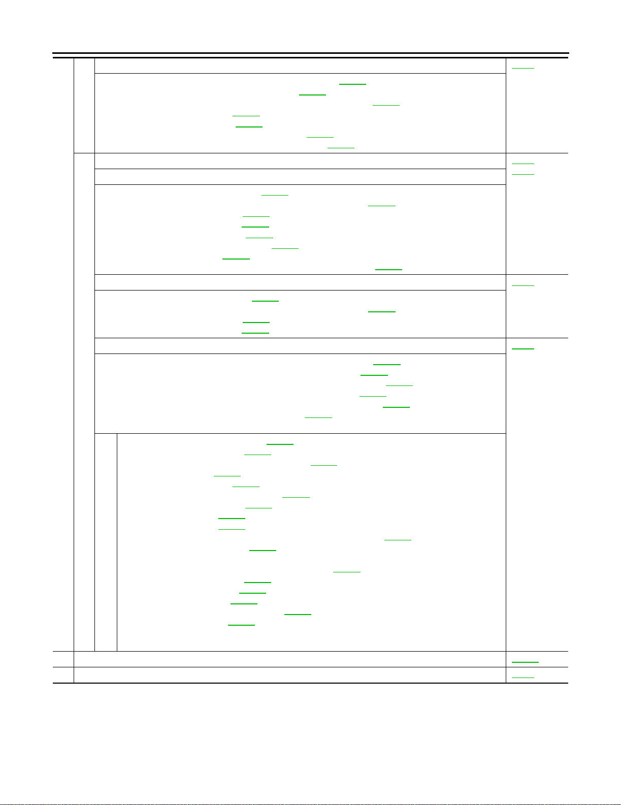
TROUBL E DIAGNOSI S - INTRODU CTION
4-2.Check at idle AT-68
❏ 1. A/T Check (Position) Indicator Lamp Does Not Come On, AT-213 .
❏ 2. Engine Cannot Be Started In P and N Position, AT-214
❏ 3. In P Position, Vehicle Moves Forw ard or Backward When Pushed, AT-215
❏ 4. In N Position, Vehicle Moves, AT-215
❏ 5. Large Shock. N → R Position , AT-217
.
.
❏ 6. Vehicle Does Not Creep Backward In R Position, AT-219
❏ 7. Vehicle Does Not Creep Forward In D, 2 or 1 Position, AT-222
4-3.Cruise test AT-71
Part-1
❏ 8. Vehicle Cannot Be Started From D
❏ 9. A/T Does Not Shift: D
❏ 10. A/T Does Not Shift: D
❏ 11. A/T Does Not Shift: D
1 → D2 or Does Not Kickd own: D4 → D2 , AT-227 .
2 → D3 , AT-229 .
3 → D4 , AT-231 .
❏ 12. A/T Does Not Perfo rm Lock-up, AT-234
1 , AT-224 .
.
❏ 13. A/T Does Not Hold Lock-up Condition, AT-235
❏ 14. Lock-up Is Not Releas e d, AT-236
.
❏ 15. Engine Speed Does Not R eturn To Id le (Light Braking D
Part-2 AT-78
❏ 16. Vehicle Does Not Start From D1 , AT-239 .
❏ 9. A/T Does Not Shift: D
❏ 10. A/T Does Not Shift: D
❏ 11. A/T Does Not Shift: D
1 → D2 or Does Not Kickd own: D4 → D2 , AT-227 .
2 → D3 , AT-229 .
3 → D4 , AT-231 .
Part-3 AT-80
4.
❏ 17. A/T Does Not Shift: D4 → D3 When Gear Selector Lever D → 3, AT-239 .
❏ 15. Engine Speed Does Not R eturn To Id le (Engine Brake In D
❏ 18. A/T Does Not Shift: D
3 → 22 , When Selector Lever D → 2 Position, AT-240 .
❏ 15. Engine Speed Does Not R eturn To Id le (Engine Brake In 2
❏ 19. A/T Does Not Shift: 2
2 → 11 , When Selector Lever 2 → 1 Positio n, AT-240 .
❏ 20. Vehicle Does Not Decelerate By Engine Brake, AT-241
❏ SELF-DIAGNOSTIC PR OCEDURE — Mark detected items.
❏ Park/neutral position (PNP) switch, AT-103
❏ A/T fluid temperature se nsor, AT-109
.
.
❏ Vehicle speed sensor·A/T (Revolution sensor), AT-115
❏ Engine speed signal, AT-120
❏ Turbine revolution sensor, AT-200
.
.
❏ Torque converter clutch solenoid valve, AT-146
❏ Line pressure solenoid valve, AT-159
❏ Shift solenoid valve A, AT-165
❏ Shift solenoid valve B, AT-170
.
.
.
❏ Throttle position sensor [accelerator pedal position (APP) sensor], AT-175
❏ Overrun clutch solenoid valve, AT-180
.
❏ Park/neutral position (PNP) & 3 position switches circuit checks, and throttle position sensor
[accelerator pedal position (APP) sensor] circuit check, AT-242
❏ A/T fluid temperature se nsor, AT-109
❏ Vehicle speed sensor·MTR, AT-196
❏ CAN communi cation line, AT-185
.
.
.
❏ Control unit (RAM), Control unit (ROM), AT-205
❏ Control unit (EEP ROM), AT-207
.
❏ Battery
❏ Others
5. ❏ For self-diagnosis NG items, inspect each component. Repair or replace the damaged parts. AT-255
6. ❏ Perform all ROAD TEST and re-mark required procedures. AT-66
.
.
.
.
AT-75
.
4 → D3 ), AT-237 .
3 ), AT-237 .
2 ), AT-237 .
.
.
.
.
.
.
AT-58
Page 77
TROUBLE DIAGNOSIS - INTRODUCTION
7. ❏ Perform DTC CON FIRMATION PROCEDURE for following MIL indicating item s and check out NG items.
Refer to EC-55, "
nostic Information" (with VQ35DE).
❏ DTC (P0731) A/T 1st gear function, AT-124 .
❏ DTC (P0732) A/T 2nd gear function, AT-129
❏ DTC (P0733) A/T 3rd gear function, AT-134
❏ DTC (P0734) A/T 4th gear function, AT-139
❏ DTC (P0744) A/T TCC S/V function (lock-up), AT-151
8. ❏ Perform the Diagnostic Procedures for all remaining items marked NG. Repair or replace the damaged parts.
Refer to the Symptom Chart when you perform the procedures. (The chart also shows some other possible
symptoms and the component inspection orders.)
9. ❏ Erase DTC from TCM and ECM memories. AT-38
Emission-related Diagnostic Information" (with QR25DE), or EC-674, "Emission-related Diag-
.
.
.
.
EC-55
EC-674
AT-40
AT-50
,
Work Flow ECS004RB
HOW TO PERFORM TROUBLE DIAGNOSES FOR QUICK AND ACCURATE REP AIR
A good understanding of the malfunction conditions can make troubleshoo ting faster and more accurate.
In general, each customer feels differently about a problem. It is important to fully understand the symptoms or
conditions for a customer complaint.
Make good use of the two sheets provided, AT-56, "
sheet" , to perform the bes t troubleshooting possible.
Information from Customer" and AT-57, "Diagnostic Work-
A
B
AT
D
E
F
G
H
M
I
J
K
L
AT-59
Page 78
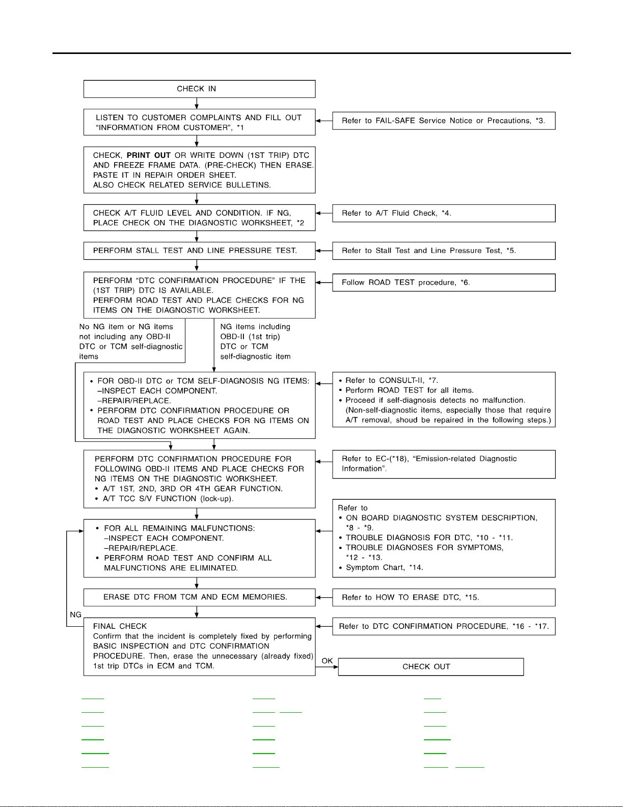
WORK FLOW CHAR T
TROUBL E DIAGNOSI S - INTRODU CTION
*1: AT-56 *2: AT-57 *3: AT-9
*4: AT-61 *5: AT-61, AT-65 *6: AT-66
*7: AT-40 *8: AT-36 *9: AT-36
*10: AT-36 *11: AT-36 *12: AT-209
*13: AT-209 *14: AT-82 *15: AT-38
*16: AT-103 *17: AT-189 *18: EC-55 , EC-674
AT-60
SAT086JI
Page 79
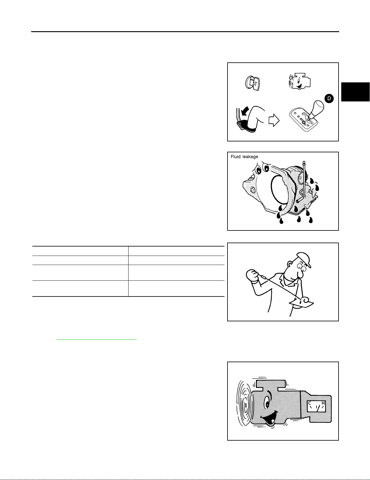
TROUBLE DIA GNOSIS - BA SIC INSPEC TION
TROUBLE DIAGNOSIS - BASIC INSPECTION PFP:00000
A/T Fluid Check ECS004RC
FLUID LEAKAGE CHECK
1. Clean area suspected of leaking. — for example, mating surface
of converter housing and transmission case.
2. Start engine, apply foot brake, place selec tor lever in D posit ion
and wait a few minutes.
3. Stop engine.
A
B
AT
D
4. Check for fresh leakage.
FLUID CONDITION CHECK
Fluid color Suspected problem
Dark or black with burned odor Wear of frictional material
Milky pink
Varnished fluid, light to dark brown and
tacky
Water contamination — Road water
entering through filler tube or breather
Oxidation — Over or under filling, —
Overheating
WCIA0053E
SAT288G
SAT638A
E
F
G
H
I
J
K
L
FLUID LEVEL CHECK
Refer to MA-29, "Checking A/T Fluid" .
Stall Test ECS004RD
STALL TEST PROCEDURE
1. Check A/T fluid and engine oil levels. If necessary, add fluid and
oil.
2. Drive vehicle fo r approximately 10 minute s or until fluid and oil
reach operating temperature.
ATF operating temperature :50 - 80°C (122 - 176°F)
SAT647B
AT-61
M
Page 80
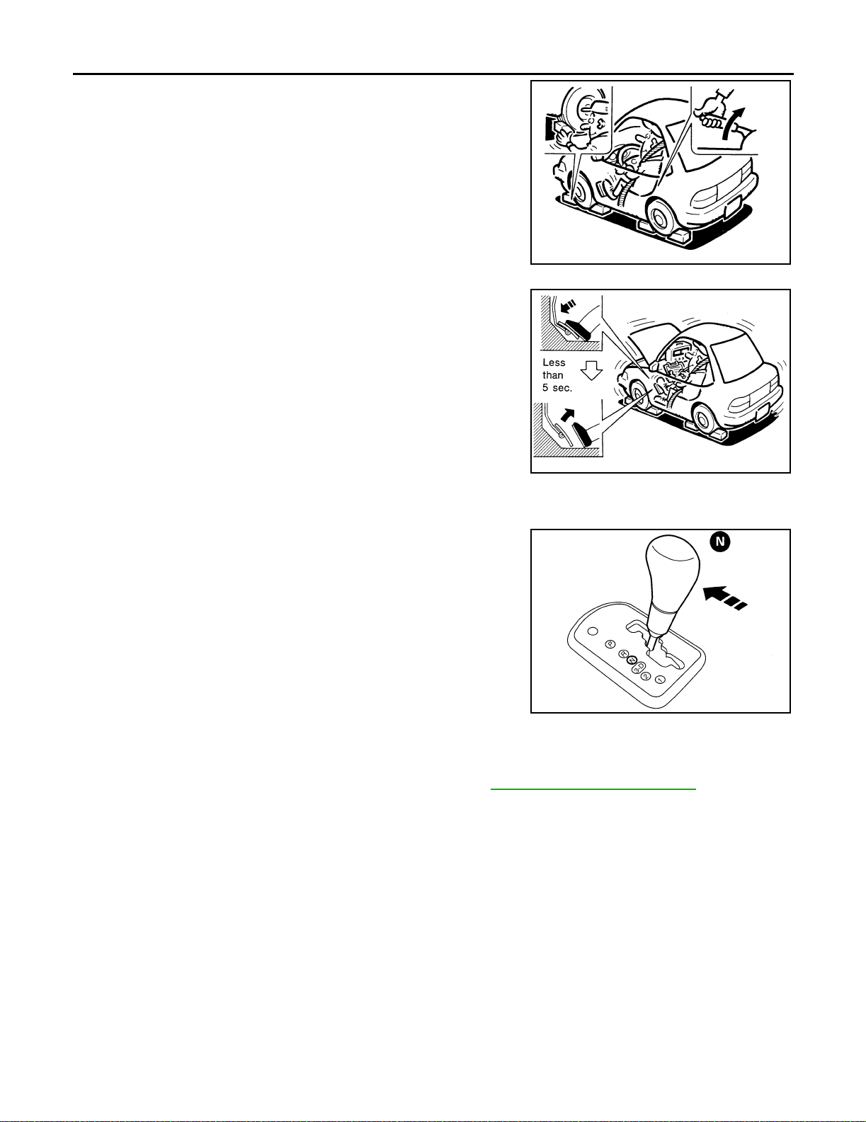
TROUBLE DIAGNOSI S - BA SIC INSPECTION
3. Set parking brake and block wheels.
4. Install a tachometer where it can be seen by driver during test.
● It is good practice to mark the point of specified engine
rpm on in dic at or.
5. Start engine, apply foot brake, and place selector lever in D
position.
6. Accelerate to wide open throttle gradually while applying foot
brake.
7. Quickly note the en gine stall revoluti on and immedi ately releas e
throttle.
● During test, never h old throttle wid e open for less than 5
seconds.
SAT513G
Stall revolution
QR25DE : 2,350 - 2,800 rpm
SAT514G
VQ35DE : 2,550 - 3,050 rpm
8. Move selector lever to N position.
9. Cool off ATF.
● Run engine at idle for at least one minute.
10. Repeat steps 5 through 9 with selector lever in 2, 1 and R posi tions.
LCIA0064E
JUDGEMENT OF STALL TEST
The test result and possible damaged components relating to each result are shown in the illustrations on next
page.
In order to pinpoint the possible damaged components, refer to AT-60, "
NOTE:
Stall revolution is too high in D, 2 or 1 position:
● Slippage occurs in 1st gea r but not in 2nd and 3rd gears. ..... Low one-way clutch slippage
● Slippage occurs in the following gears:
1st through 3rd gears in 3 position and engine brake functions.
1st and 2nd gears in 2 position and engine brake functions wi th accelerator pedal released (fully closed
throttle). ..... Forward clutch or forward one-way clutch slippage
Stall revolution is too high in R position:
● Engine brake does not function in 1 position. ..... Low & reverse brake slippage
● Engine brake functions in 1 position. ..... Reverse clutch slippage
Stall revolution within specifications:
● Vehicle does not achieve speed of mor e than 80 km/h (50 MPH). ..... One-w ay clutch seizure in torque
converter housi ng
CAUTION:
Be careful since automatic fluid temperature increases abnormally.
WORK FLOW CHART" .
AT-62
Page 81

TROUBLE DIA GNOSIS - BA SIC INSPEC TION
● Slippage occurs in 3rd and 4th gears in D position. ..... High clutch slippage
● Slippage occurs in 2nd and 4th gear in D position. ..... Brake band slippage
● Engine brake does not functio n in 2nd and 3rd gea rs in D position, 2nd gear in 2 position, and 1st gea r in
1 position.
Stall revolution less than specifications:
A
B
AT
D
E
F
G
M
H
I
J
K
L
AT-63
Page 82
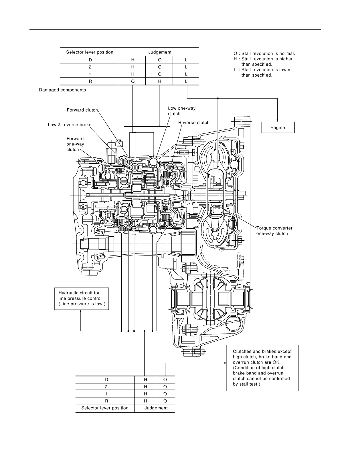
TROUBLE DIAGNOSI S - BA SIC INSPECTION
● Poor acceleration during starts. ..... One-way clutch seizure in torque converter
AT-64
SAT499K
Page 83
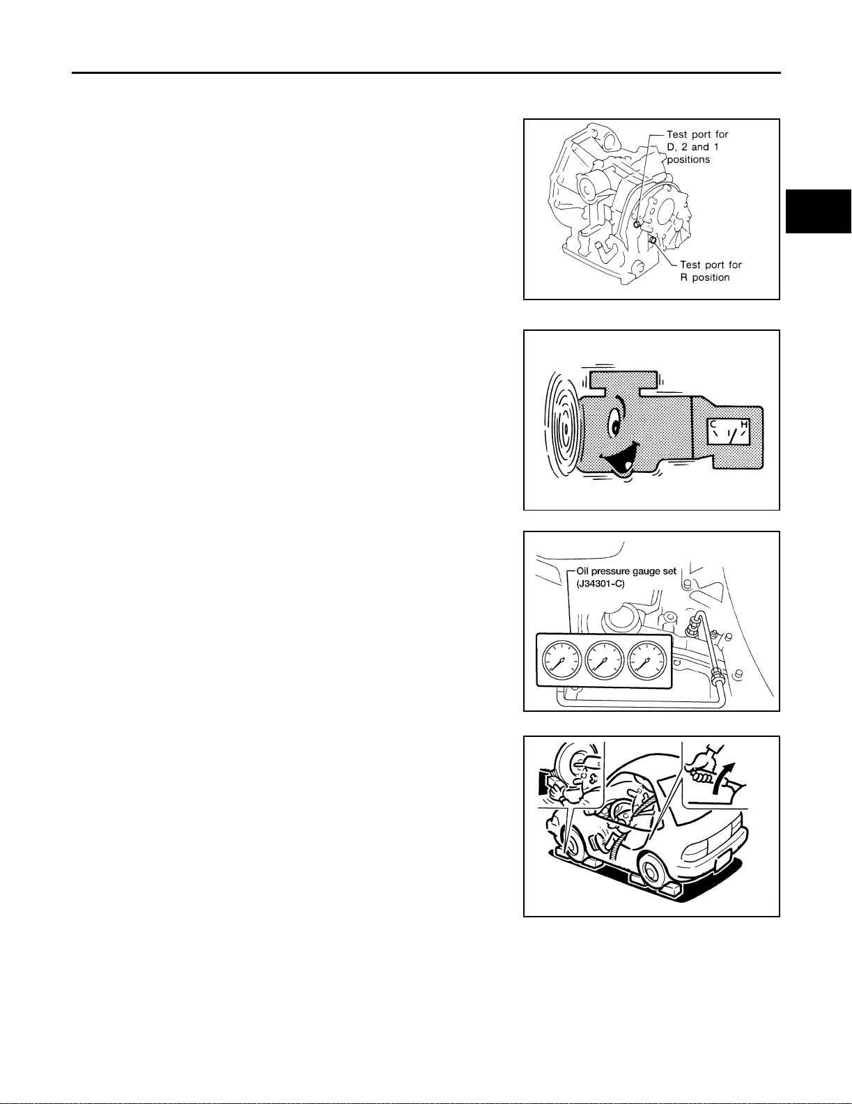
TROUBLE DIA GNOSIS - BA SIC INSPEC TION
Line Pressure Test ECS004RE
LINE PRESSURE TEST PORTS
Location of line pressure test ports are shown in the illustration.
● Always replace pressure plugs as they are self-sealing
bolts.
SAT301FA
A
B
AT
D
LINE PRESSURE TEST PROCEDURE
1. Check A/T fluid and engine oil levels. If necessary, add fluid and
oil.
2. Drive vehicle fo r approximately 10 minute s or until fluid and oil
reach operating temperature.
ATF operating temperature :50 - 80°C (122 -
176°F)
3. Install pressure gauge to corresponding line pressure port.
SAT647B
AAT898
E
F
G
H
I
J
K
L
4. Set parking brake and block wheels.
● Cont inue to d epre ss brake p eda l fully wh ile lin e pressu re
test is being performed at stall speed.
AT-65
M
SAT513G
Page 84
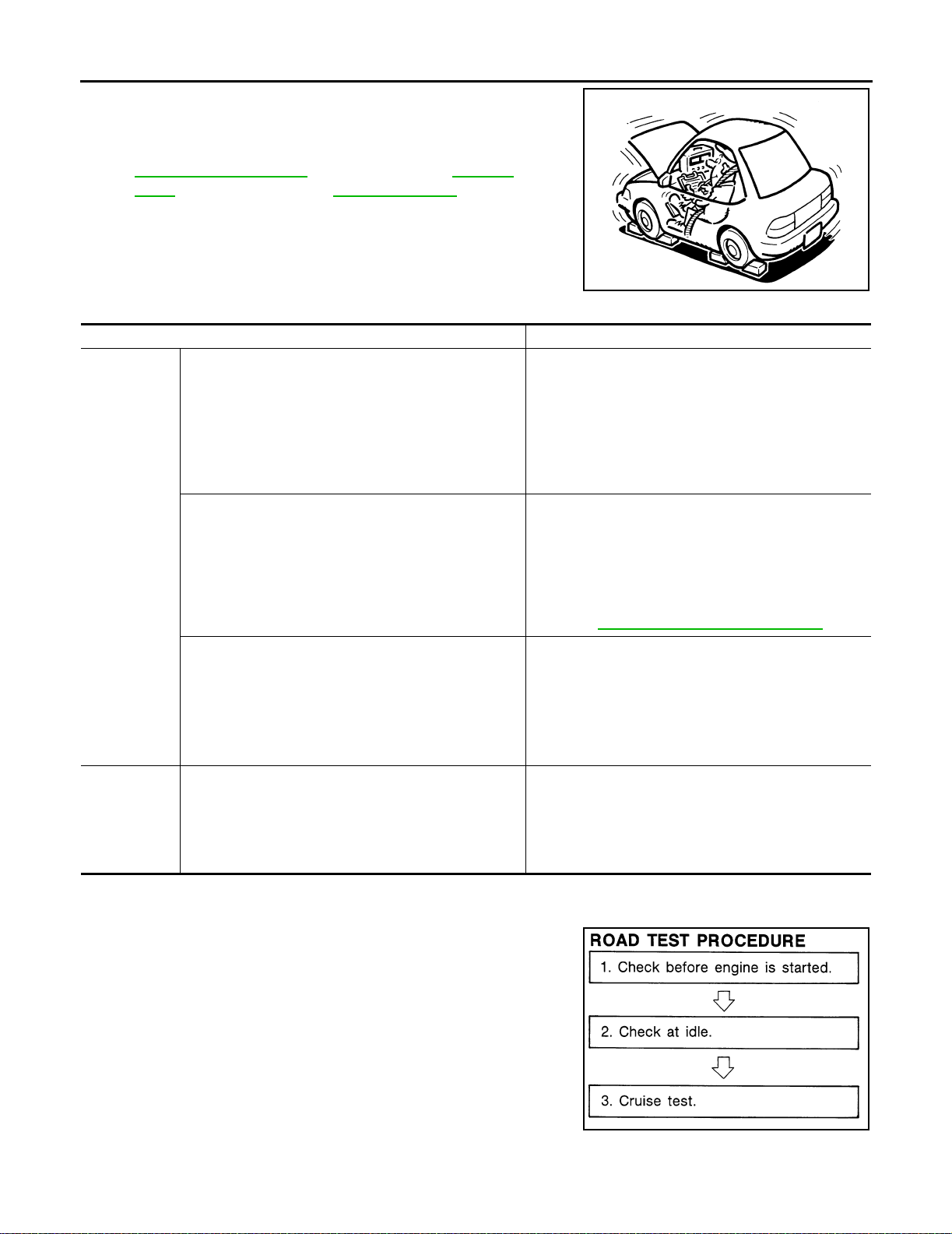
TROUBLE DIAGNOSI S - BA SIC INSPECTION
5. Start engine and measure line pressure at idle and stall speed.
● When measu ring line pressure at stall speed, follow the
stall test procedure.
AT-65, "
Test"
Line Pressure
: Refer to SDS, AT-365,
"Line Pressure"
JUDGEMENT OF LINE PRESSURE TEST
Judg ement Suspected pa rts
Line pressure is low in all positions.
Line pressure is low in particular position.
At idle
Line pressure is high.
Line pressure is low.
At stall speed
SAT493G
● Oil pump wear
● Control piston damage
● Pressure regula tor valve or plug sticking
● Spring for pressure r egulator valve da m aged
● Fluid pressure leakage between oil strainer and pres-
sure regulator valve
● Clogged strainer
● Fluid pressur e leakage between manual v al v e and par-
ticular clut ch
● For example, line pressure is:
− Low in R and 1 positions, but
− Normal in D and 2 positions.
Therefore, fluid leakage exists at or around low and
reverse brake circuit.
Refer to AT-19, "
● A/T fluid temperature sensor damaged
● Line pressure solenoid valve sticking
● Short circuit of line pressure solenoid valve circuit
● Pressure modifier valve sticking
● Pressure regula tor valve or plug sticking
● Open in dropping resistor circuit
● Line pressure solenoid valve sticking
● Short circuit of line pressure solenoid valve circuit
● Pressure regula tor valve or plug sticking
● Pressure modifier valve sticking
● Pilot valve sticking
CLUTCH AND BAND CHART" .
Road Test ECS004RF
DESCRIPTION
● The purpose of the test is to determine overall performance of A/
T and analyze causes of problems.
● The road test consists of the following three parts:
1. Check before engine is started
2. Check at idle
3. Cruise test
SAT786A
AT-66
Page 85
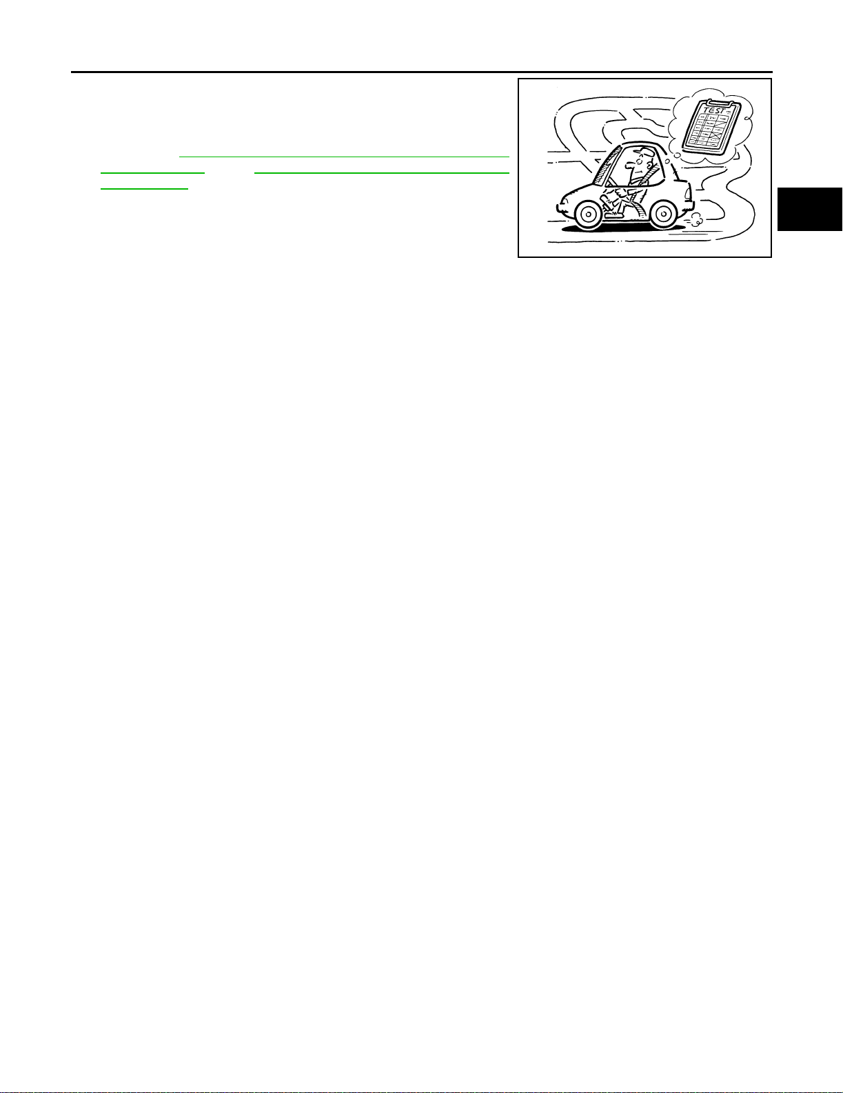
TROUBLE DIA GNOSIS - BA SIC INSPEC TION
● Before road test, familiarize yourself with all test procedures and
items to check.
● Conduct tests on all items until specified symptom is found.
Troubleshoot items which check out No Good after road test.
Refer to AT-36, "
DESCRIPTION" , and AT-209, "TROUBLE DIAGNOSIS FOR
SYMPTOMS" .
ON BOARD DIAGNOSTIC SYSTEM
A
B
AT
SAT496G
D
E
F
G
M
H
I
J
K
L
AT-67
Page 86
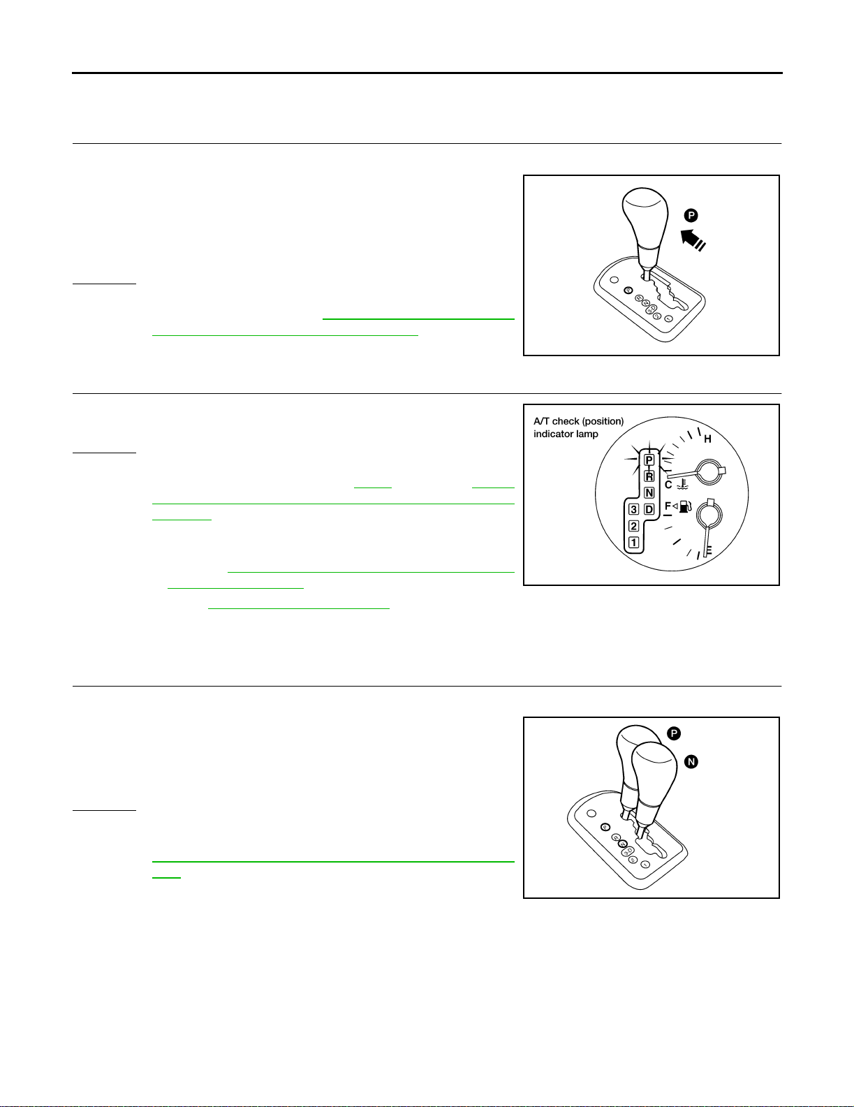
TROUBLE DIAGNOSI S - BA SIC INSPECTION
1. CHECK BEFORE ENGINE IS STARTED
1. CHECK A/T CHECK (POSITION) INDICATOR LAMP
1. Park vehicle on flat sur face.
2. Move selector lever to P position.
3. Turn ignition switch to OFF p osition. Wait at least 5 seconds.
4. Turn ignition switch to ON position. (Do not start engine.)
5. Does A /T check (position) indi cator lamp come on for about 2
seconds?
Yes or No
Yes >> GO TO 2.
No >> Sto p ROAD TEST. Go to AT-213 , "
tion) Indicator Lamp Do es Not Come On" .
1. A/T Che ck (Posi-
2. CHECK A/T CHECK (POSITION) INDICATOR LAMP
Does A/T check (posi tion) OFF indicator lamp flicker for about 8 seconds?
Yes or No
Yes >> Perform self-diagnosis and check NG items on the
DIAGNOSTIC WORKSHEET, AT-57
"TCM SELF-DIAGNOSTIC PROCEDURE (NO
TOOLS)" .
No >> 1. Turn ignition switch to OFF position.
2. Perform self-diagnosis and note NG items.
Refer to AT-51, "
DURE (NO TOOLS)" .
3. Go to AT-68, "
TCM SELF-DIAGNOSTIC PROCE-
2. CHECK AT IDLE" .
. Refer to AT-51,
LCIA0043E
LCIA0044E
2. CHECK AT IDLE
1. CHECK ENGINE START
1. Park vehicle on flat sur face.
2. Move selector lever to P position.
3. Turn ignition switch to OFF position.
4. Turn ignition switch to START position.
5. Is eng ine started?
Yes or No
Yes >> GO TO 2.
No >> Mark the box on the DIAGNOSTIC WORKSHEET. Go to
AT-214, "
tion" . Continue ROAD TEST.
2. Engine Cann ot Be Started In P and N P osi-
LCIA0065E
AT-68
Page 87
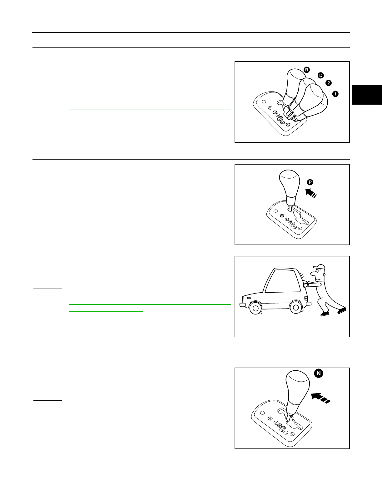
TROUBLE DIA GNOSIS - BA SIC INSPEC TION
2. CHECK ENGINE START
1. Turn ignition switch to ACC position.
2. Move selector lever to D, 1, 2 or R position.
3. Turn ignition switch to START position.
4. Is engine started?
Yes or No
Yes >> Mark the box on the DIAGNOSTIC WORKSHEET. Go to
AT-214, "
tion" . Continue ROAD TEST.
No >> GO TO 3.
2. Engine Cannot Be Started In P and N Posi-
3. CHECK VEHICLE MOVE
1. Move selector lever to P position.
2. Turn ignition switch to OFF position.
3. Release parking brake.
A
B
AT
D
LCIA0066E
E
F
G
H
4. Push vehi cle forward or backward.
5. Does vehicle move whe n it is pushed forward or backward?
6. Apply parking brake.
Yes or No
Yes >> Mark the box on the DIAGNOSTIC WORKSHEET. Go to
AT-215, "
Backward Wh en Pushed" . Continue ROAD TEST.
No >> GO TO 4.
3. In P Position, Vehicle Moves Forward or
4. CHECK VEHICLE MOVE
1. Start engine.
2. Move selector lever to N position.
3. Release parking brake.
4. Does vehicle move forward or backward?
Yes or No
Yes >> Mark the box on the DIAGNOSTIC WORKSHEET. Go to
AT-215, "
ROAD TEST.
No >> GO TO 5.
4. In N Position, Vehicle Moves" . Continue
LCIA0043E
SAT796A
I
J
K
L
M
AT-69
LCIA0064E
Page 88
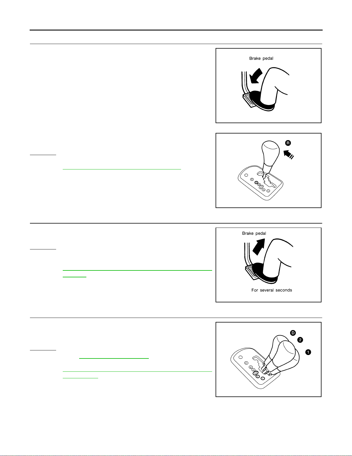
TROUBLE DIAGNOSI S - BA SIC INSPECTION
5. CHECK SHIFT LOCK
1. Apply foot brake.
2. Move selector lever to R position.
3. Is there la rge shock when changing from N to R position?
Yes or No
Yes >> Mark the box on the DIAGNOSTIC WORKSHEET . Go to
AT-217, "
ROAD TEST.
No >> GO TO 6.
5. Large Shock. N → R Position" . Continue
SAT797A
6. CHECK VEHICLE MOVE
1. Relea se foot brake for several seconds.
2. Does vehicle creep backward when foot brake is released?
Yes or No
Yes >> GO TO 7.
No >> Mark the box on the DIAGNOSTIC WORKSHEET. Go to
AT-219, "
Position" . Continue ROAD TEST.
6. Vehicle Does Not Creep Backward In R
7. CHECK VEHICLE MOVE
1. Move s elec tor lev er t o D , 2 a nd 1 posi tions a nd c heck i f vehic le
creeps forward.
2. Does vehicle creep forward in all three positions?
Yes or No
Ye s >> Go to AT-71, "3. CRUISE TEST" .
No >> Mark the box on the DIAGNOSTIC WORKSHEET. Go to
AT-222, "
or 1 Position" . Continue ROAD TEST.
7. Vehicle Does Not Cre ep Forward in D, 3, 2
LCIA0068E
SAT799A
AT-70
LCIA0069E
Page 89
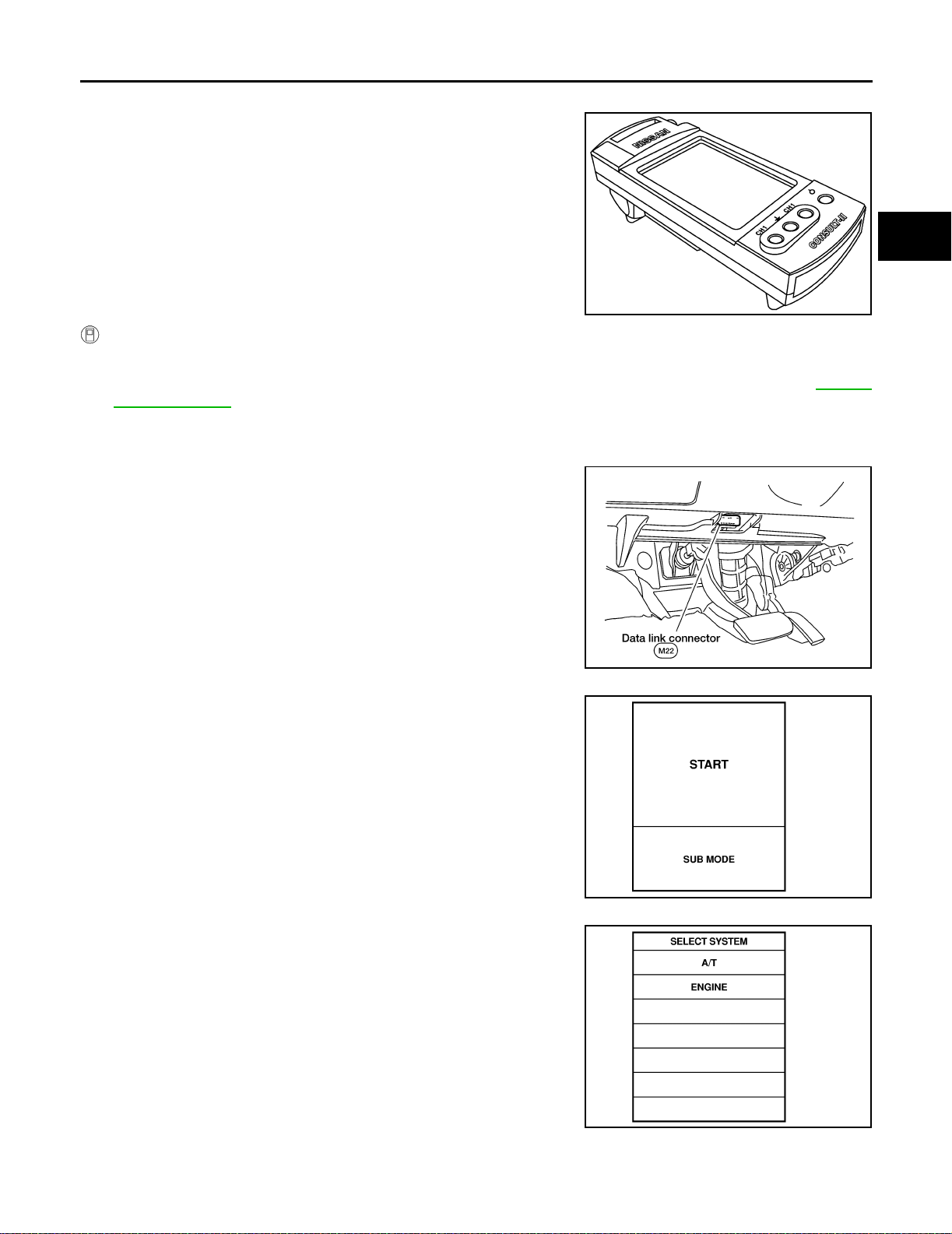
TROUBLE DIA GNOSIS - BA SIC INSPEC TION
3. CRUISE TEST
● Check all ite ms listed in Parts 1 through 3.
A
B
AT
SAT601J
With CONSULT-II
● Using CONSULT-II, conduct a cruise test and record the resul t.
● Print the result and e nsure that shifts and lock-ups take place a s per Shift Schedule. Refer to AT-364,
"Shift Schedule"
CONSULT-II Set ting Proce dure
1. Turn ignition switch OFF.
2. Connect CONSULT-II to data link connector, which is located i n
left side dash panel.
LCIA0042E
3. Turn ignition switch ON.
4. Touch “START”.
D
E
F
G
H
I
J
K
5. Touch “A/T ”.
L
M
SAT586J
SAT014K
AT-71
Page 90
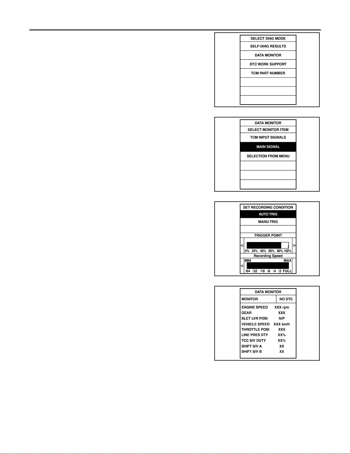
TROUBLE DIAGNOSI S - BA SIC INSPECTION
6. Touch “DATA MONITOR”.
7. Touch “MAIN SIGNALS” or “TCM INPUT SIGNALS”.
8. See “N umeri cal Di spla y”, “B arch art Di splay ” o r “Line Grap h Dis play”.
SAT971J
9. Touch “SETTIN G” to set recording condition (“AUTO TRIG” or
“MANU TRIG”) and touch “BACK”.
10. Touch “Start”.
11. When performing cruise test, touch “RECORD”.
SAT175K
SAT973J
AT-72
SAT134K
Page 91
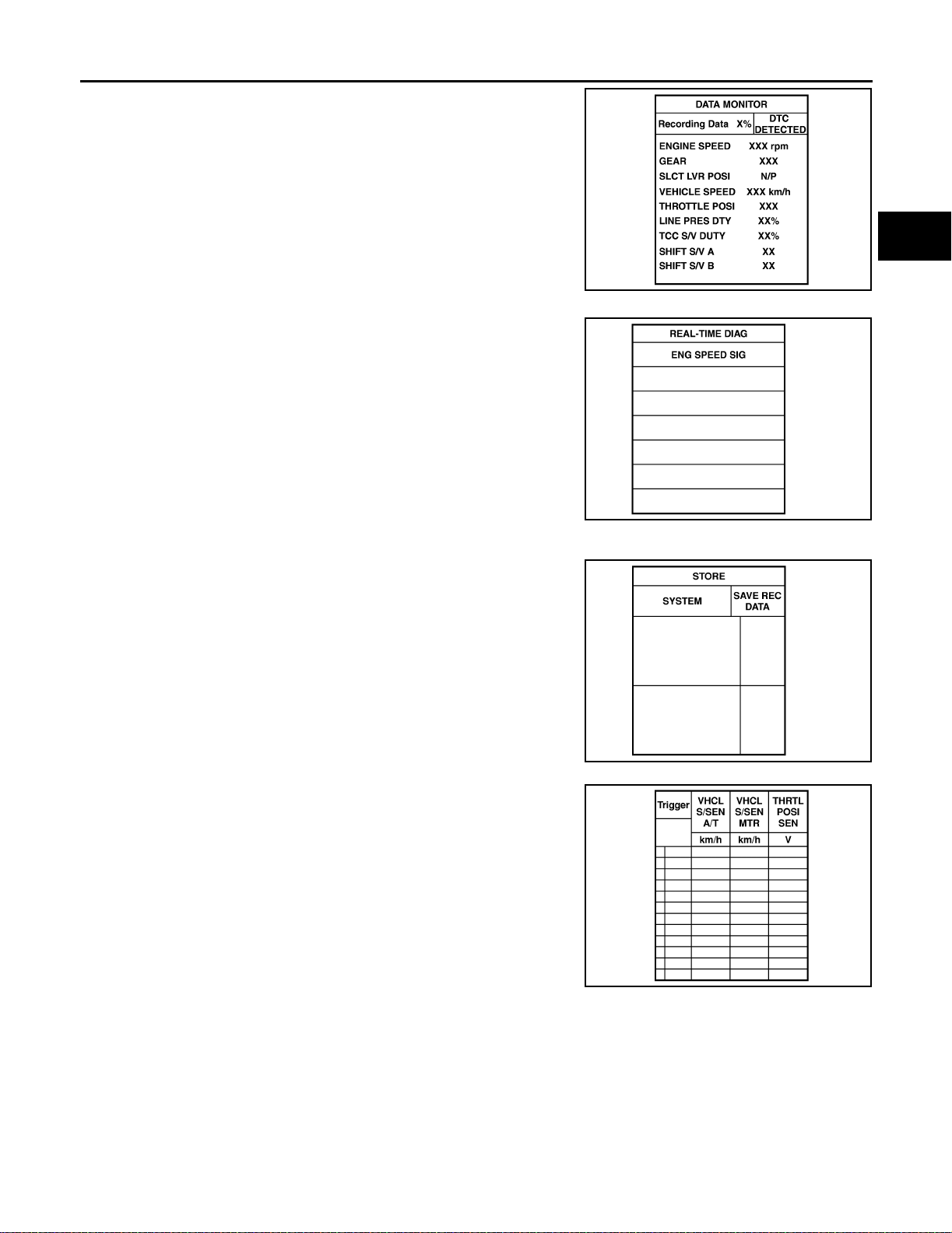
TROUBLE DIA GNOSIS - BA SIC INSPEC TION
12. After finishing cruise test part 1, touch “STOP”.
13. Touch “STORE” and touch “BACK”.
A
B
AT
SAT135K
D
E
F
G
SAT987J
14. Touch “D ISPLAY”.
15. Touc h “PRINT ” .
16. Check the monitor data printed out.
17. Continue cruise test part 2 and 3.
H
I
J
K
SAT974J
L
M
SAT975J
AT-73
Page 92
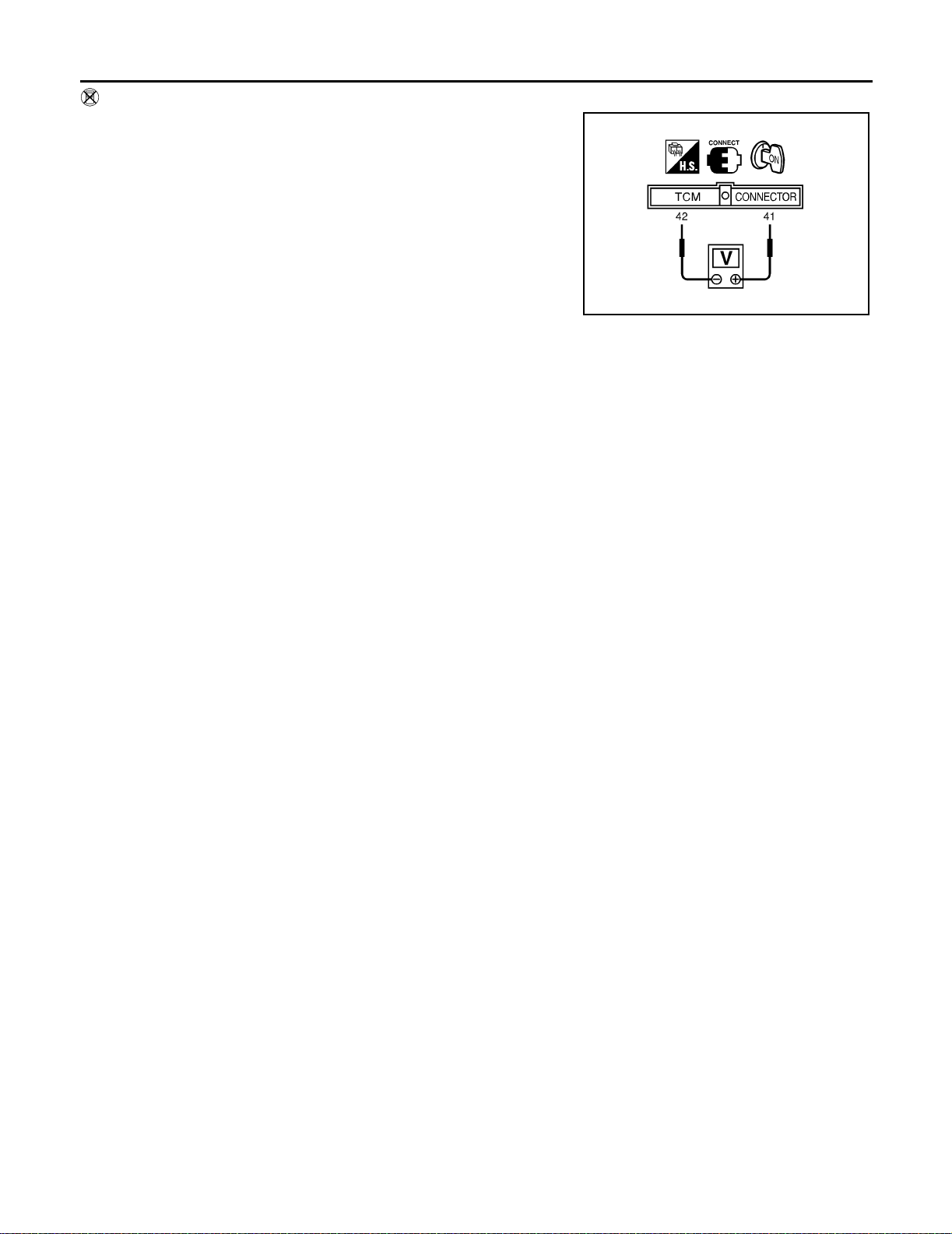
TROUBLE DIAGNOSI S - BA SIC INSPECTION
Without CONSULT-II
● Throttle position sensor can be checked by voltage across termi-
nals 41 (W) and 42 (B) of TCM.
LCIA0097E
AT-74
Page 93
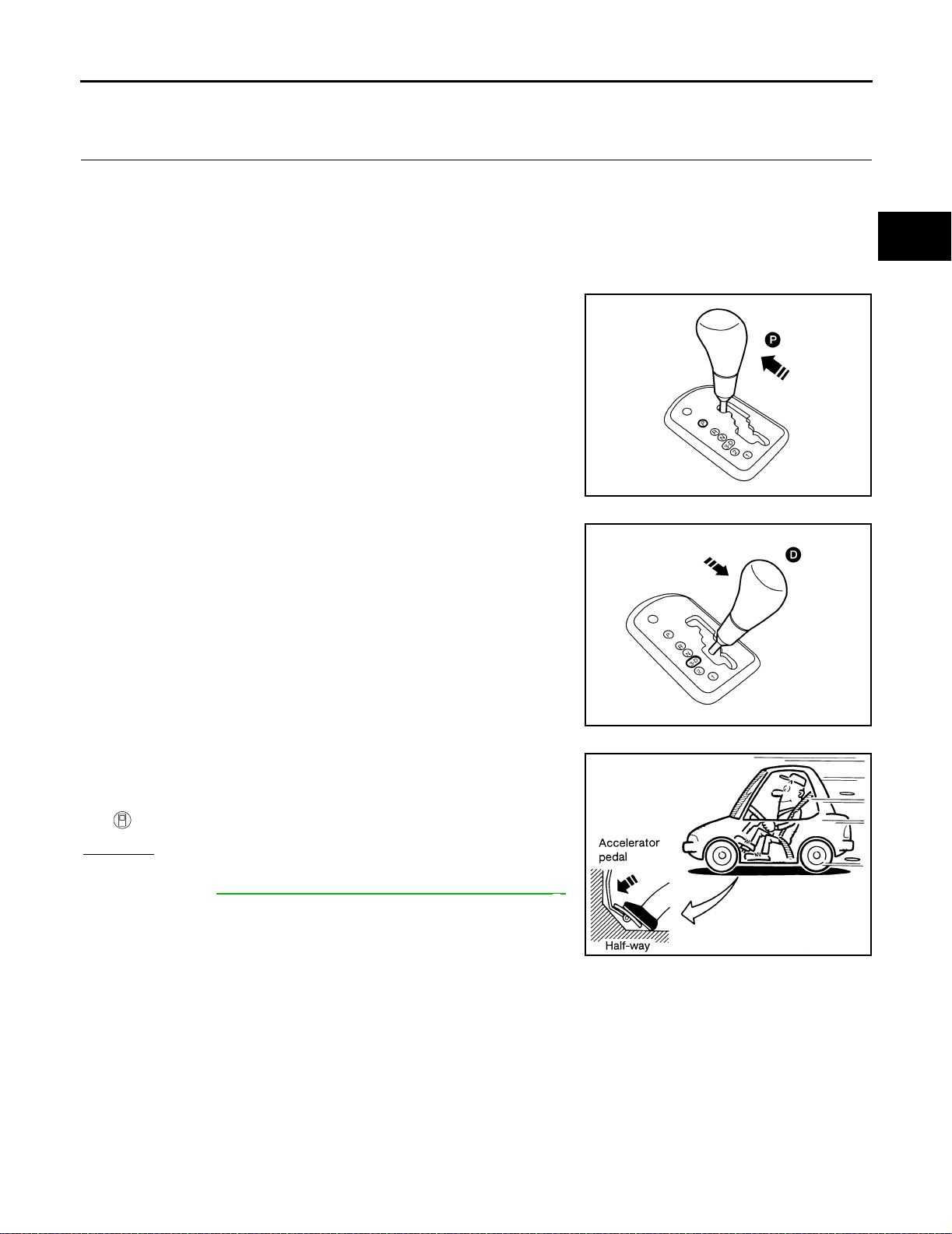
TROUBLE DIA GNOSIS - BA SIC INSPEC TION
Cruise Test — Part 1
1. CHECK STARTING GEAR (D1 ) POSITION
A
1. Drive vehic le for approximately 10 minutes to warm engine oil and ATF up to operating temperature.
ATF operating tempera-
:50 - 80°C (122 - 176°F)
ture
2. Park vehicle on flat surface.
3. Set gear selector lever to D position.
4. Move selector lever to P position.
5. Start engine.
LCIA0043E
6. Move selector lever to D position.
B
AT
D
E
F
G
H
I
7. Accelerate vehicle by constantly depressing accelerator pedal
half-way.
8. Does vehicle start from D
1 ?
Read gear position.
Yes or No
Yes >> GO TO 2.
No >> Go to AT-224, "
8. Vehicle Cannot Be Started From D 1" .
Continue ROAD TEST.
J
LCIA0045E
K
L
M
SAT495G
AT-75
Page 94
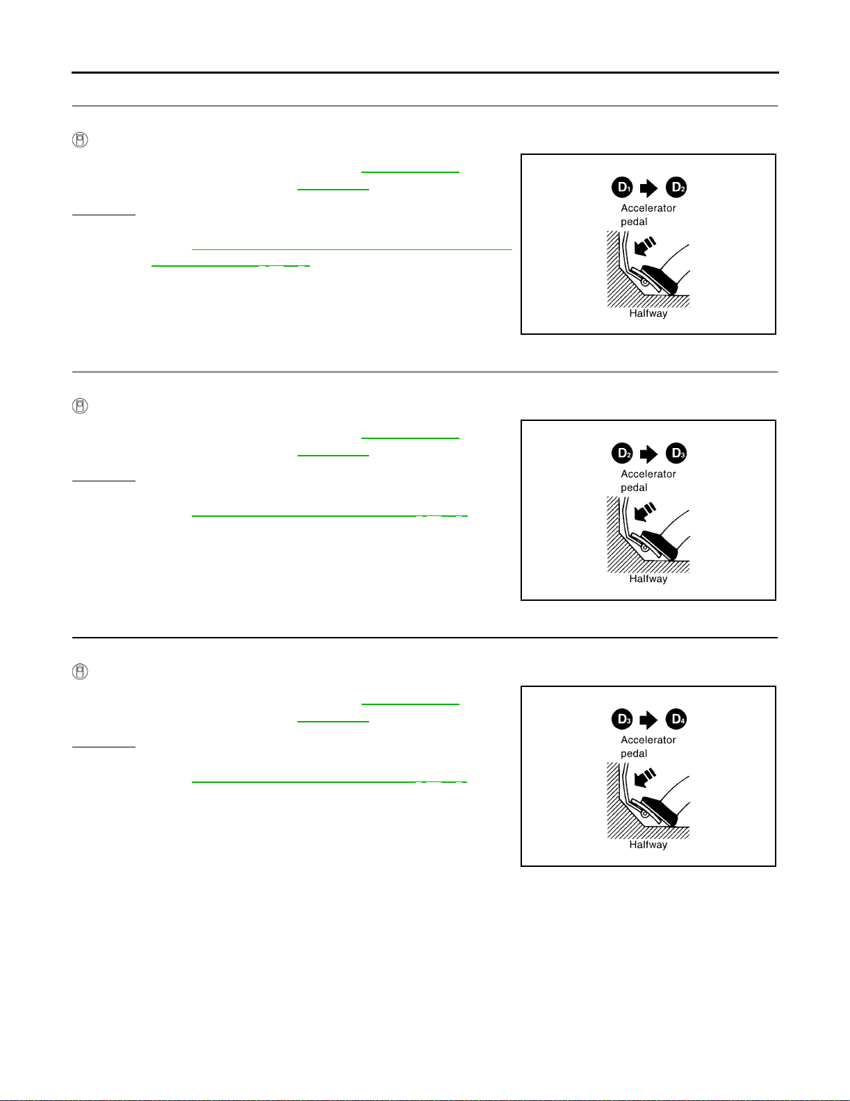
TROUBLE DIAGNOSI S - BA SIC INSPECTION
2. CHECK SHIFT UP (D1 TO D2 )
Does A/T shift from D
1 to D2 at the specified speed?
Read gear position, throttle opening and vehicle speed.
Specified speed when
shifting fr om D
1 to D2
:Refer to AT-364, "Shift
Schedule" .
Yes or No
Yes >> GO TO 3.
No >> Go to AT-227, "
9. A/T Does Not Shift: D1 → D2 or Does
Not Kickdown: D4 → D2" . Continue ROAD TEST.
3. CHECK SHIFT UP (D2 TO D3 )
Does A/T shift from D
Read gear position, throttle opening and vehicle speed.
Specified speed when
shifting fr om D
Yes or No
Yes >> GO TO 4.
No >> Go to AT-229, "
tinue ROAD TEST.
2 to D3 at the specified speed?
:Refer to AT-364, "Shift
2 to D3
Schedule"
10. A/T Do es Not Shi ft: D 2 → D3" . Con-
SAT954I
4. CHECK SHIFT UP (D3 TO D4 )
Does A/T shift from D
Read gear position, throttle opening and vehicle speed.
Specified speed when
shifting fr om D
Yes or No
Yes >> GO TO 5.
No >> Go to AT- 231, "
tinue ROAD TEST.
3 to D4 at the specified speed?
:Refer to AT-364, "Shift
3 to D4
Schedule" .
11. A/T Do es N ot Sh ift : D 3 → D4" . Con-
SAT955I
SAT956I
AT-76
Page 95
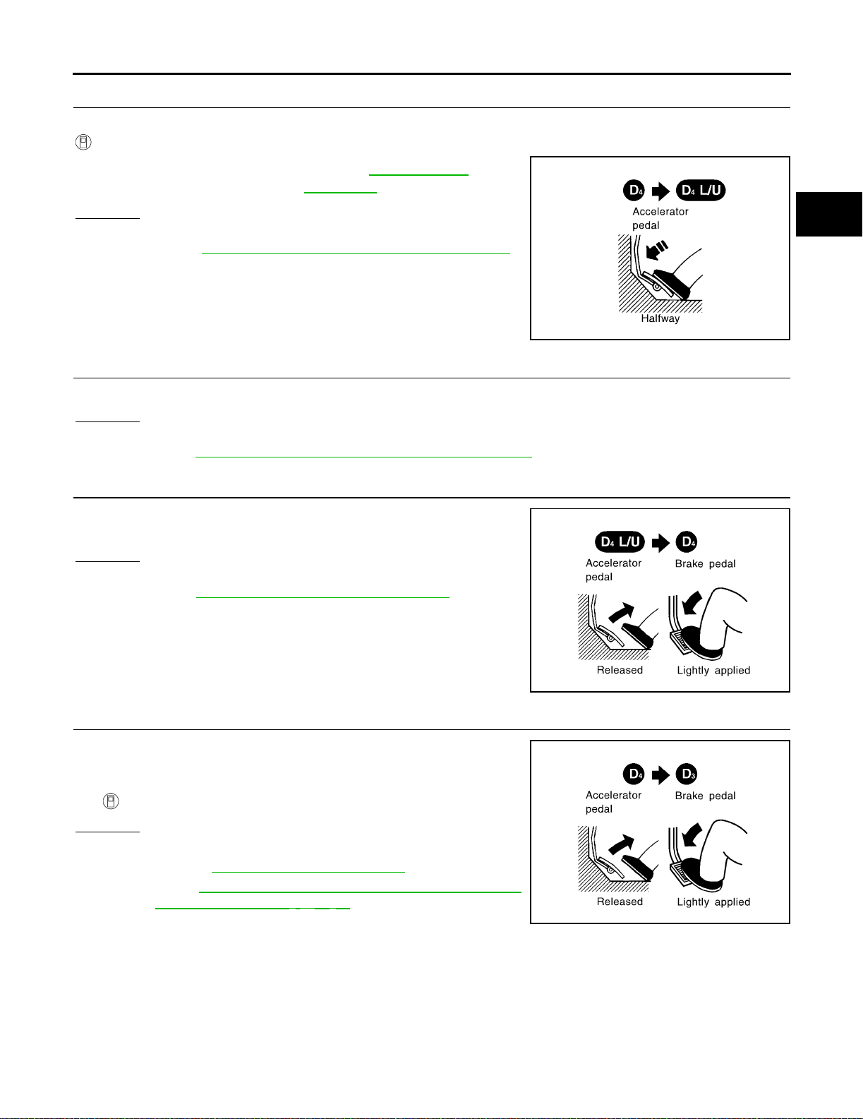
TROUBLE DIA GNOSIS - BA SIC INSPEC TION
5. CHECK LOCK-UP (D4 TO D4 L/U)
Does A/T perform lock-up at the specified speed?
Read vehicle speed, throttle opening when lock-up duty becomes 94%.
Specified speed when
lock-up occurs
Yes or No
Yes >> GO TO 6.
No >> Go to AT-234, "
Continue ROAD TEST.
:Refer to AT-364, "
Schedule" .
12. A/T Does Not Perform Lock-up" .
Shift
6. CHECK HO LD LOCK-UP
Does A/T hold lock-up condition for more than 30 seconds?
Yes or No
Yes >> GO TO 7.
No >> Go to AT-235, "
13. A/T Does Not Hold Lock-up Condition" .
7. CHECK SHIFT DOWN (D4 L/U TO D4 )
1. Release accelerator pedal.
2. Is lock-up released when accelerator pedal is released?
Yes or No
Yes >> GO TO 8.
No >> Go to AT-236, "
ROAD TEST.
14. Lock-up Is N ot Rel eased" . C ontinu e
SAT957I
A
B
AT
D
E
F
G
H
I
J
8. CHECK SHIFT DOWN (D4 TO D3 )
1. Decelerate vehicle by applying foot brake lightly.
2. Does engine speed return to idle smoot hly when A/T is shifted
from D
Yes or No
Yes >> 1. Stop vehicle.
No >> Go to AT-237, "
4 to D3 ?
Read gear position and engine speed.
2. Go to AT-78, "
Idle (Light Braking D4 → D3 )" . Continue ROAD TEST.
Cruise Test — Part 2" .
15. Engine Sp eed Does Not Return To
K
SAT958I
L
M
SAT959I
AT-77
Page 96
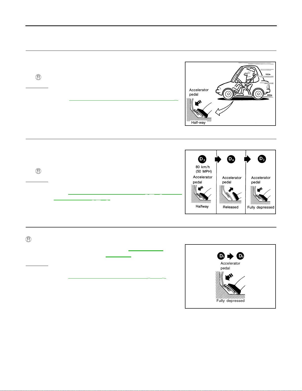
TROUBLE DIAGNOSI S - BA SIC INSPECTION
Cruise Test — Part 2
1. CHECK STARTING GEAR (D1 ) POSITION
1. Confirm gear selector lever is in D position.
2. Accelerate vehicle by half throttle again.
3. Does vehicle start from D
Read gear p osition.
Yes or No
Yes >> GO TO 2.
No >> Go to AT-239, "
Continue ROAD TEST.
1 ?
16. Vehicle Does Not Start From D1" .
2. CHECK SHIFT UP AND SHIFT DOWN (D3 TO D4 TO D2 )
1. Accelerate vehicle to 80 km/h (50 MPH) as shown in illustration.
2. Relea se accelerator pedal and then quickly depress it fully.
3. Does A/T shift fr om D
depressed fully?
Read gear position and throttle opening.
Yes or No
Yes >> GO TO 3.
No >> Go to AT-227, "
Not Kickdown: D4 → D2" . Continue ROAD TEST.
4 to D2 as soon as acceler ator pedal is
9. A/T Does Not Shift: D1 → D2 or Does
SAT495G
3. CHECK SHIFT UP (D2 TO D3 )
Does A/T shift from D
Read gear position, throttle opening and vehicle speed.
Specified speed when
shifting fr om D
Yes or No
Yes >> GO TO 4.
No >> Go to AT-229, "
tinue ROAD TEST.
2 to D3 at the specified speed?
:Refer to AT-364, "Shift
2 to D3
10. A/T Do es Not Shi ft: D 2 → D3" . Con-
Schedule" .
SAT404H
SAT960I
AT-78
Page 97
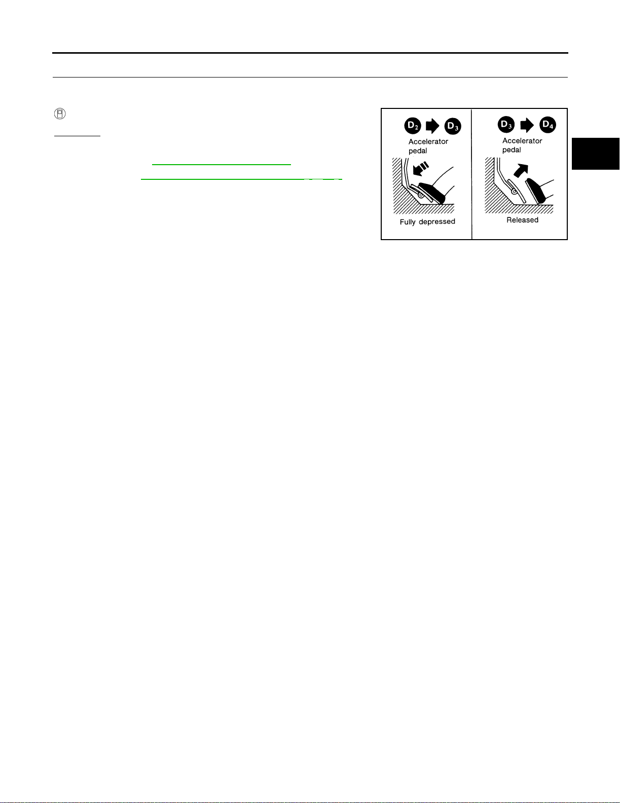
TROUBLE DIA GNOSIS - BA SIC INSPEC TION
4. CHECK SHIFT UP (D3 TO D4 ) AND ENGINE BRAKE
Release accelerator pedal after shifting from D
Does A/T shift from D
3 to D4 and does vehic le decelerate by engine brake?
Read gear position, throttle opening and vehicle spe ed.
Yes or No
Yes >> 1. Stop vehicle.
2. Go to AT-80, "
No >> Go to AT-231, "
Cruise Test — Part 3" .
11. A/T D oes N ot Shift: D 3 → D4" . Con-
tinue ROAD TEST.
2 to D3 .
SAT405H
A
B
AT
D
E
F
G
H
M
I
J
K
L
AT-79
Page 98
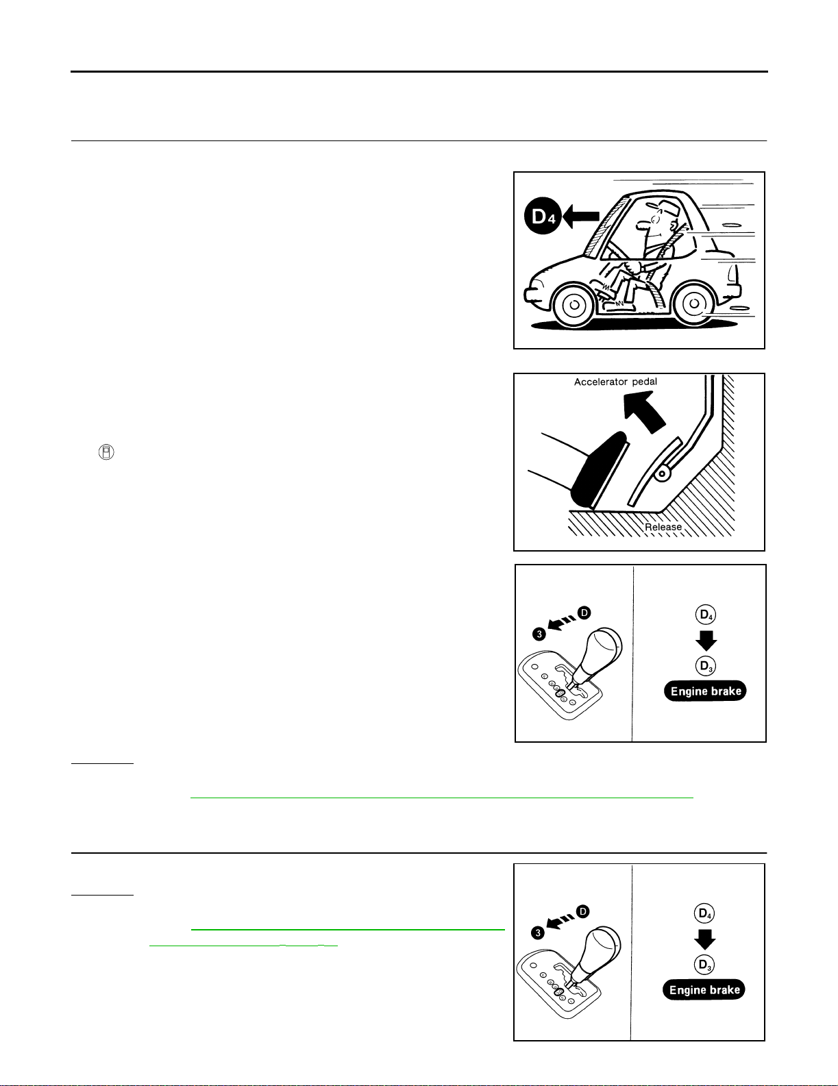
TROUBLE DIAGNOSI S - BA SIC INSPECTION
Cruise Test — Part 3
1. VEHICLE SPEED (D4 ) POSITION
1. Confirm gear selector lever is in D position.
2. Accelerate vehicle using half-throttle t o D
3. Release accelerator pedal.
4. Move gear selector lever from D position to 3 position while driv-
ing in D
5. Does A/T shift from D
4 .
4 to 3?
Read gear position and vehicle speed.
4 .
SAT812A
Yes or No
Yes >> GO TO 2.
No >> Go to AT-2 3 9 , "
17. A/T Does Not Shift: D4 → 33 , When A/T Selector L ever D → 3" . Con tinue
ROAD TEST.
2. CHECK ENG IN E BRAK E
Does vehicle decelerate by engine brake?
Yes or No
Yes >> GO TO 3.
No >> Go to AT-237, "
Idle (L ight Braking D4 → D3 )" . Continue ROAD TEST.
15. Engine Spe ed Does Not Return To
SAT813A
LCIA0071E
AT-80
LCIA0071E
Page 99
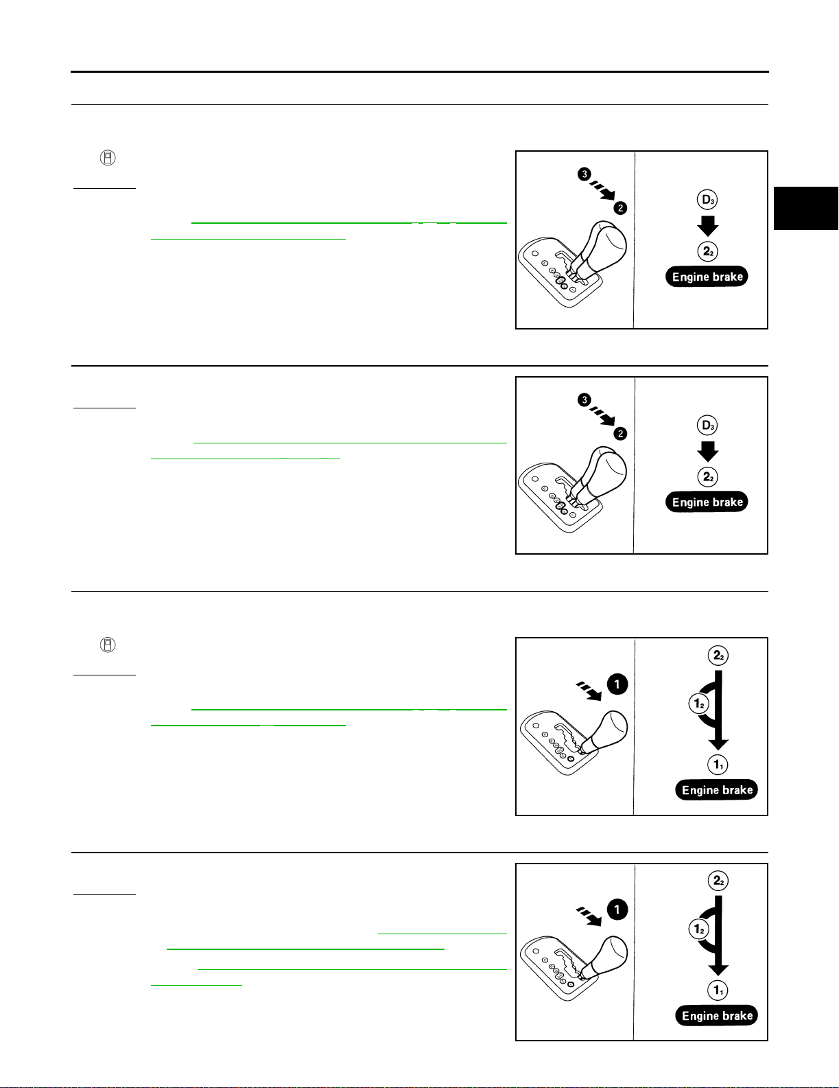
TROUBLE DIA GNOSIS - BA SIC INSPEC TION
3. CHECK SHIFT DOWN (33 TO 22 )
1. Move selector lever from 3 to 2 position while driving in 3
2. Does A/T shift from 3
Read gear position.
Yes or No
Yes >> GO TO 4.
No >> Go to AT-240, "
Selector Lever 3 → 2 Position" . Continue ROAD TEST.
3 to 22 ?
18. A/T Doe s Not Shift: 33 → 22 , When
4. CHECK ENGINE BRAKE
Does vehicle decelerate by engine brake?
Yes or No
Yes >> GO TO 5.
No >> Go to AT-237, "
Idle (Light Braking D4 → D3 )" . Continue ROAD TEST.
15. Engine Sp eed Does Not Return To
3 .
LCIA0072E
A
B
AT
D
E
F
G
H
5. CHECK SHIFT DOWN (22 TO 11 )
1. Move selector lever from 2 to 1 position while driving in 2
2. Does A/T shift from 2
Read gear position.
Yes or No
Yes >> GO TO 6.
No >> Go to AT-2 40 , "
Selector Lever 2 → 1 Position" . Continue ROAD TEST.
2 to 11 position?
19. A/T Does Not Shift: 22 → 11 , When
6. CHECK ENGINE BRAKE
Does vehicle decelerate by engine brake?
Yes or No
Yes >> 1. Stop vehicle.
2. Perform self- diagnosis. Refer t o AT-51, "
DIAGNOSTIC PROCEDURE (NO TOOLS)" .
No >> Go to AT-241, "
Engine Brake" . Continue ROAD TEST.
20. Vehicle Does Not Decelerate By
TCM SELF-
2 .
LCIA0072E
LCIA0073E
I
J
K
L
M
AT-81
LCIA0073E
Page 100
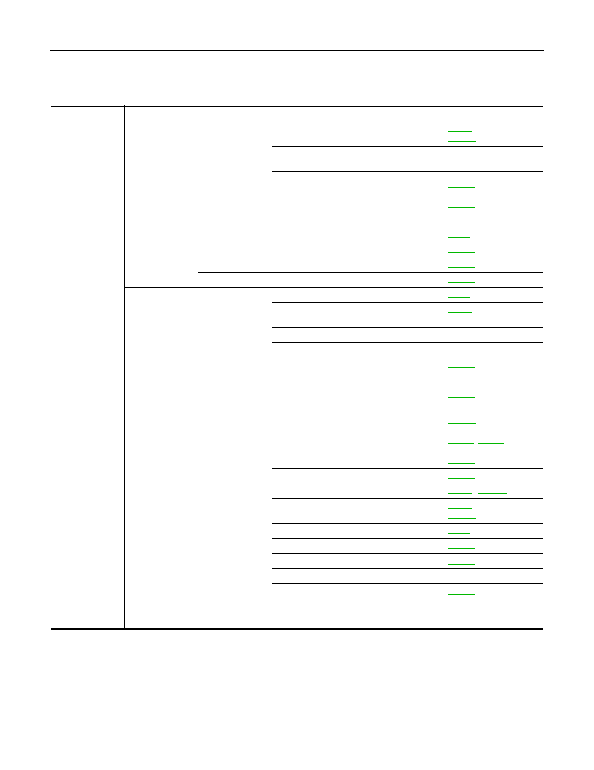
TROUBLE DIAGNOSIS - GEN ERAL DESCRIPTION
TROUBL E DIAGNOSI S - GENERAL D ESCRIPTION
PFP:00000
Symptom Chart ECS004RG
Numbers are arranged in order of inspection.
Perform inspections starting with number one and work up.
Items Symptom Conditi o n Diagnostic I tem Referenc e Pag e
No Lock-up
Engagement/
TCC Inoperative
Shift Shock
Torque converter
is not locked up.
Torque converter
clutch pist on slip.
Lock-up point is
extrem ely hi g h or
low.
Sharp shock in
shifting from N to
D position.
1. Thrott le posi tion sen sor [acce lerat or peda l
positi on (AP P) sen sor] adjustment
2. Vehicle speed sensor·A/T (Revolution
sensor) and vehicle speed sensor·MTR
3. Park/n eut r al pos i ti o n (PNP ) switch adjustment
ON vehicl e
OFF vehicle 9. Torque converter AT-268
ON vehicl e
OFF vehicle 7. Torque converter AT-268
ON vehicl e
ON vehicl e
OFF vehicle 9. Forward clutch AT-313
4. Engine speed signal AT-120
5. A/T fluid temperature sensor AT-109
6. Line pressure test AT-65
7. Torque converter clutch solenoid valve AT-146
8. Control valve assembly AT-255
1. Fluid leve l AT-61
2. Thrott le posi tion sen sor [acce lerat or peda l
positi on (AP P) sen sor] adjustment
3. Line pressure test AT-65
4. Torque converter clutch solenoid valve AT-146
5. Line pressure solenoid valve AT-159
6. Control valve assembly AT-255
1. Thrott le posi tion sen sor [acce lerat or peda l
positi on (AP P) sen sor] adjustment
2. Vehicle speed sensor·A/T (Revolution
sensor) and vehicle speed sensor·MTR
3. Torque converter clutch solenoid valve AT-146
4. Control valve assembly AT-255
1. Engine idling rpm EC-38
2. Thrott le posi tion sen sor [acce lerat or peda l
positi on (AP P) sen sor] adjustment
3. Line pressure test AT-65
4. A/T fluid temperature sensor AT-109
5. Engine speed signal AT-120
6. Line pressure solenoid valve AT-159
7. Control valve assembly AT-255
8. Accumula t or N-D AT-268
EC-49
(with QR25DE)
EC-657
(with VQ35DE)
, AT-196
AT-115
AT-257
EC-49 (with QR25DE)
EC-657
(with VQ35DE)
(with QR25DE)
EC-49
EC-657
(with VQ35DE)
AT-115
, AT-196
, EC-657
EC-49 (with QR25DE)
(with VQ35DE)
EC-657
AT-82
 Loading...