

Page 1
Edition: July 2005
Revision: July 2005
Publication No. SM6E-1L31U0
QUICK REFERENCE INDEX
A
GENERAL INFORMATION
B ENGINE
C
TRANSMISSION/
TRANSAXLE
D DRIVELINE/AXLE
E SUSPENSION
F BRAKES
G STEERING
H RESTRAINTS
I BODY
J AIR CONDITIONER
K ELECTRICAL
L MAINTENANCE
M INDEX
GI
General Information
EM
Engine Mechanical
LU
Engine Lubrication System
CO
Engine Cooling System
EC
Engine Control System
FL
Fuel System
EX
Exhaust System
ACC
Accelerator Control System
CL
Clutch
MT
Manual Transaxle
AT
Automatic Transaxle
FAX
Front Axle
RAX
Rear Axle
FSU
Front Suspension
RSU
Rear Suspension
WT
Road Wheels & Tires
BR
Brake System
PB
Parking Brake System
BRC
Brake Control System
PS
Power Steering System
SB
Seat Belts
SRS
Supplemental Restraint System (SRS)
BL
Body, Lock & Security System
GW
Glasses, Window System & Mirrors
RF
Roof
EI
Exterior & Interior
IP
Instrument Panel
SE
Seat
ATC
Automatic Air Conditioner
MTC
Manual Air Conditioner
SC
Starting & Charging System
LT
Lighting System
DI
Driver Information System
WW
Wiper, Washer & Horn
BCS
Body Control System
LAN
LAN System
AV
Audio Visual & Telephone System
ACS
Auto Cruise Control System
PG
Power Supply, Ground & Circuit Elements
MA
Maintenance
IDX
Alphabetical Index
A
B
C
D
E
F
G
H
I
J
K
L
M
© 2005 NISSAN NORTH AMERICA, INC.
All rights reserved. No p a rt of this Se rvice Man ual may be reproduc ed or sto re d in a retrie val system, or tran smitted in any
form, or by any means, electronic, mecha nical, photo-co pying, recording or oth erwise, without the prio r written permissi on
of Nissan North America, Inc., Gardena, California.
-1
Page 2

This manual contains maintenance and repair procedures for the
2006 NISSAN ALTIMA.
In order to assure your safety and the efficient functioning of the vehicle,
this manual should be read thoroughly. It is especially important that the
PRECAUTIONS in the GI section be completely understood before starting
any repair task.
All information in this manual is based on the latest product information
at the time of publication. The right is reserved to make changes in specifications and methods at any time without notice.
IMPORTANT SAFETY NOTICE
The proper performance of service is essential for both the safety of
the technician and the efficient functioning of the vehicle.
The service methods in this Service Manual are described in such a
manner that the service may be performed safely and accurately.
Service varies with the procedures used, the skills of the technician
and the tools and parts available. Accordingly, anyone using service
procedures, tools or parts which are not specifically recommended
by NISSAN must first be completely satisfied that neither personal
safety nor the vehicle’s safety will be jeopardized by the service
method selected.
-2
Page 3
PLEASE HELP MAKE THIS SERVICE MANUAL BETTER!
Your comments are important to NISSAN and will help us to improve our Service Manuals.
Use this form to report any issues or comments you may have regarding our Service Manuals.
Please print this form and type or write your comments below. Mail or fax to:
Nissan North America, Inc.
Technical Service Information
39001 Sunrise Drive, P.O. Box 9200
Farmington Hills, MI USA 48331
FAX: (248) 488-3910
SERVICE MANUAL: Model: Year:
PUBLICATION NO. (Refer to Quick Reference Index ):
Please describe any Service Manual issues or problems in detail:
Page number(s)
Note: Please include a copy of each page, marked with your comments.
Are the trouble diagnosis procedures logical and easy to use? (circle your answer) YES NO
If no, what page number(s)?
Please describe the issue or problem in detail:
Is the organization of the manual clear and easy to follow? (circle your answer) YES NO
Please comment:
What information should be included in NISSAN Service Manuals to better support you in servicing or
repairing customer vehicles?
Note: Please include a copy of each page, marked with your comments.
DATE: YOUR NAME: POSITION:
DEALER: DEALER NO.: ADDRESS:
CITY: STATE/PROV./COUNTRY: ZIP/POSTAL CODE:
Page 4
QUICK REFERENCE CHART: ALTIMA (EQUIPPED WITH
2.5L, QR ENGINE)
2006
QUICK REFERENCE CHART: ALTIMA (EQUIPPED WITH 2.5L, QR ENGINE)
PFP:00000
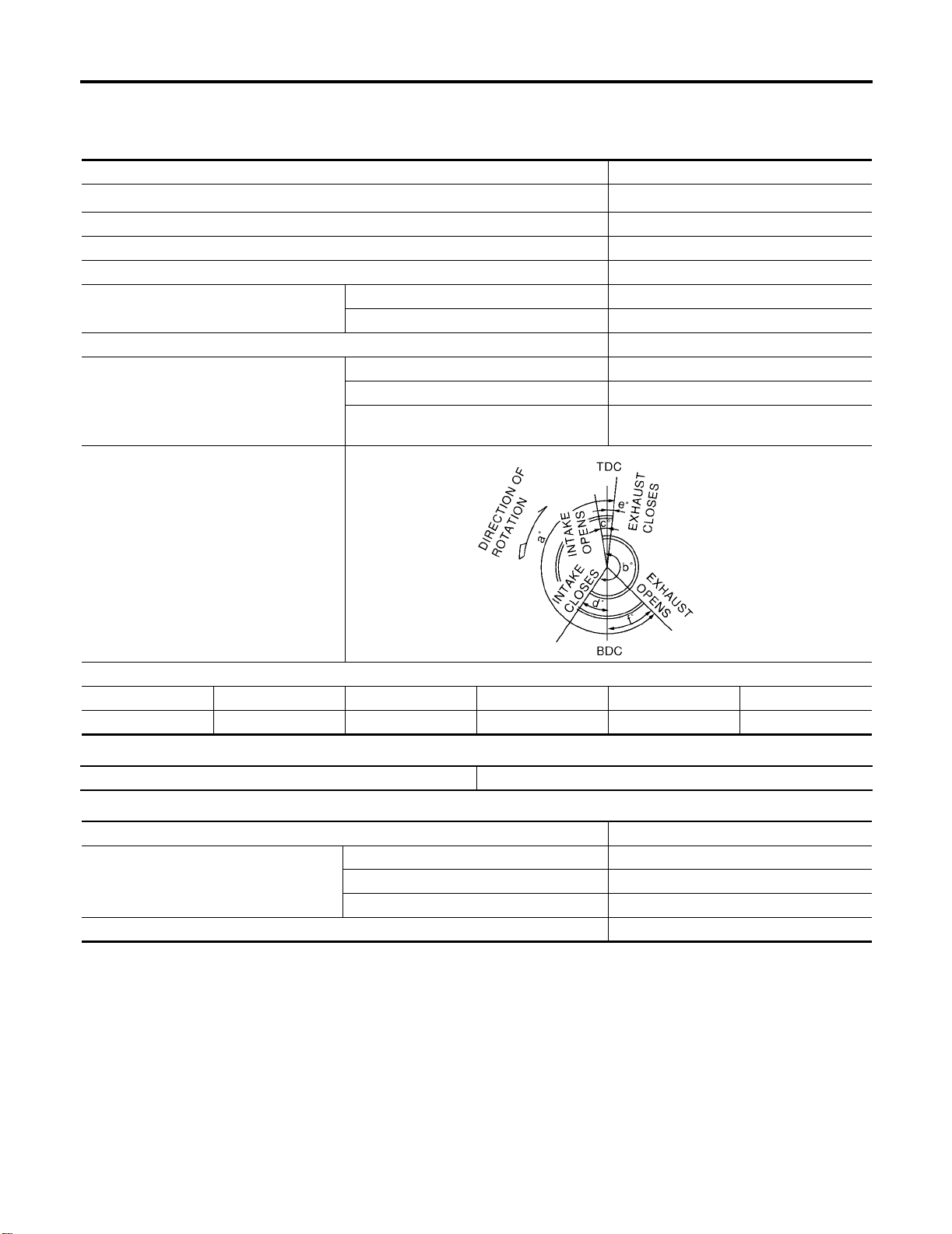
Engine Tune-Up Data
Cylinder arrangement In-line 4
3
Displacement cm
Bore and stroke mm (in) 89.0 x 100 (3.50 x 3.94)
Valve arrangement DOHC
Firing order 1-3-4-2
Number of piston ring s
Compression ratio 9.5:1
Compression pressure
kPa (kg/cm
Valve timing
2
(in3 )
, psi) / 250 rpm
Compression 2
Oil 1
Standard 1,250 (12.8, 181.3)
Minimum 1,060 (10.8, 153.7)
Differential limit
between cylinders
2,488 (151.82)
100 (1.0, 14)
ELS001PZ
PBIC0187E
abcdef
224° 244° 0° 64° 3° 41°
Drive Belt Deflection and Tension
Tension of drive belts Auto adjustment by auto-tensioner
Spark Plugs (Double Platinum Tipped)
Make NGK
Standard PLFR5A-11
Type
Plug gap (nominal) 1.1 mm (0.043 in)
Hot PLFR4A-11
Cold PLFR6A-11
Unit: degree
Page 5

QUICK REFERENCE CHART: ALTIMA (EQUIPPED WITH
2.5L, QR ENGINE)
2006
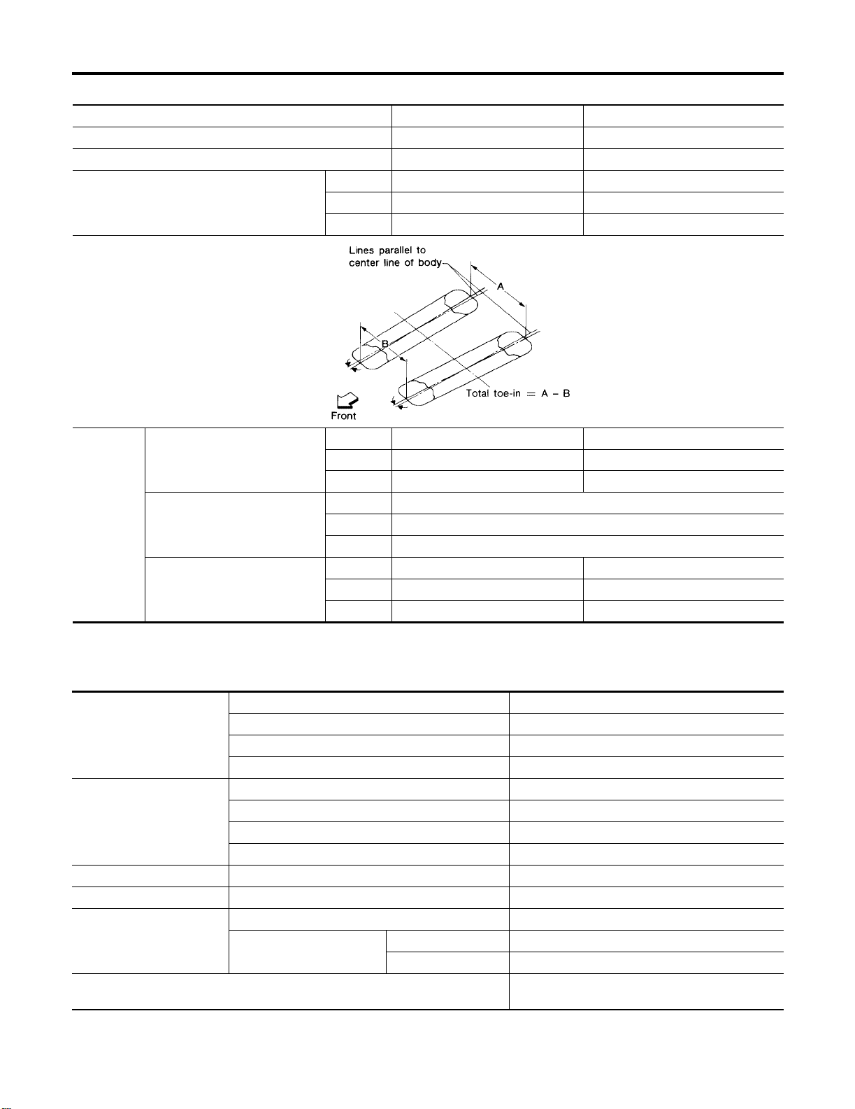
Front Wheel Alignment (Unladen*1)
Market United Stated and Canada Mexico
Engine QR25DE QR25DE
Model Base/S Base/S
Tire size 215/60R16 215/60R16
Camber
Degree minute (decimal degree)
Caster
Degree minute (decimal degree)
Kingpin inclination
Degree minute (decimal degree)
Total toe-in
Distance (A − B)
mm (in)
Angle (left, right)
Degree minute (decimal
degree)
Wheel turning
angle
Full turn*2
*1: Fuel, engine coolant and engine oil full. Spare tire, jack, hand too ls an d mats in designa te d posi tion s.
*2: On power steering m odels, wheel turning f orce (at circumferen ce of steering wheel) of 98 to 147 N (10 to 15 kg, 22 to 33 lb) with
engine idle.
Inside
Degree minute (decimal
degree)
Outside
Degree minute (decimal
degree)
Minimum −1°00′ (−1.00°)-0°40′ (-0.67°)
Nominal −0°15′ (−0.25°)0°05′ (0.08°)
Maximum 0°30′ (0.50°)0°50′ (0.83°)
Left and right
difference
Minimum 2°05′ (2.08°)1°55′ (1.92°)
Nominal 2°50′ (2.83°)2°40′ (2.67°)
Maximum 3°35′ (3.58°)3°25′ (3.42°)
Left and right
difference
Minimum 13°50′ (13.83°)13°10′ (13.17°)
Nominal 14°35′ (14.58°)13°55′ (13.93°)
Maximum 15°20′ (15.33°)14°40′ (14.67°)
Minimum −0.5 (−0.02) 0 .0 (0.00)
Nominal 0.5 (0.02) 1.0 (0.04)
Maximum 1.5 (0.06 ) 2 .0 (0.08)
Minimum −0°04′ (−0.07°) −0°03′ (−0.05°)
Nominal 0°02′ (0.03°)0°03′ (0.03°)
Maximum 0°08′ (0.13°)0°09′ (0.15°)
Minimum 34°30′ (34.5°)
Nominal 38°00′ (38.0°)
Maximum 39°00′ (39.0°)
Nominal 30°30′ (30.5°)30°30′ (30.5°)
45′ (0.75°) or less
45′ (0.75°) or less
ELS001Q0
Page 6
QUICK REFERENCE CHART: ALTIMA (EQUIPPED WITH
2.5L, QR ENGINE)
2006
Rear Wheel Alignment (Unladen*)
Market United States and Canada Mexico
Engine QR25DE QR25DE
Model Base / S Base / S
Minimum −0° 04′ (−0.07°)-0° 30' (0.50°)
Camber
Degree minute (Decimal degree)
Distance (A − B)
mm (in)
Distance difference
Total toe-in
*: Fuel, engine coolant and engine oil full. Spare tire, jack, hand tools and m ats in designat ed positions.
between RH and LH side
mm (in)
Angle (left plus right)
Degree minute (decimal
degree)
Nominal −0° 34′ (−0.57°)0° 0' (0°)
Maximum −0° 64′ (−1.07°)0° 30' (0.50°)
SFA234AC
Minimum 2.4 (0.09) 1.3 (0.05)
Nominal 3.9 (0.15) 2.8 (0.11)
Maximum 5.4 (0.21) 4.3 (0.17)
Minimum −2 (−0.08)
Nominal 0 (0)
Maximum 2 (0.08)
Minimum 0° 6′ (0.10°)0° 3' (0.05°)
Nominal 0° 10′ (0.17°)0° 7' (0.12°)
Maximum 0° 14′ (0.23°)0° 11' (0.18°)
ELS001Q1
Brake
Brake model CLZ25VD disc brake
Front brake
Rear brake
Master cylinder Cylinder bore diameter 23.81 (15/16)
Control valve Screw in type 30 × 0.4 (1.18 × 0.02)
Brake booster
Recommended brake fluid
Cylinder bore diameter 57.2 (2.25)
Pad Length × width × thickness 125.6 × 46 × 11 (4.94 × 1.81 × 0.43)
Rotor outer diameter × thickness 296 × 24 (11.7 × 0.94)
Brake model AD9A disc brake
Cylinder bore diameter 34.9 (1.3740)
Pad Length × width × thickness 89.1 × 39.5 × 10 (3.508 × 1.555 × 0.31 )
Rotor outer diameter × thickness 292 × 9 (11.5 × 0.35)
Booster model M215T
Diaphragm diameter
Primary 230 (9.06)
Secondary 205 (8.07)
Genuine NISSAN Super Heavy Duty Brake Fluid
or equivalent DOT 3 (US FMVSS No. 16)
ELS001Q2
Unit: mm (in)
Page 7
QUICK REFERENCE CHART: ALTIMA (EQUIPPED WITH
2.5L, QR ENGINE)
Disc Brake - Repair Limits
Brake model CLZ25VD (Front) AD9A (Rear)
Pad wear limit Minimum thickness 2.0 (0.079) 1.5 (0.059)
Maximum runout 0.07 (0.0028)
Rotor repair limit
Brake Pedal
Minimum thickness 22.0 (0.866) 8.0 (0.31)
Maximum thickness variation
(at least 8 positions)
0.015 (0.0006)
2006
Unit: mm (in)
Unit: mm (in)
WFIA0423E
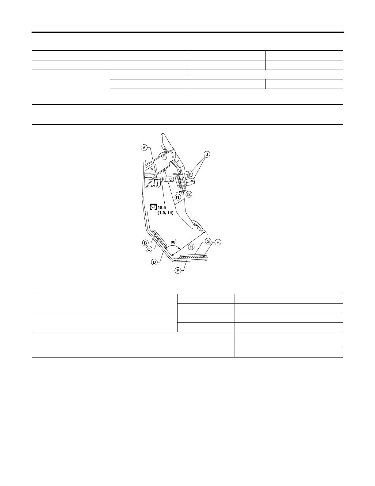
Free height “H”*
Pedal height (with engine running, brake pedal force 490 N
{50 kg-f, 110 lb-f) “H”
Clearance “I1” or “I2” between pedal stopper and threaded end of stop lam p swit ch or
ASCD switch
Pedal play 3 - 11 (0.12 - 0.43)
*: Measured from surface of dash reinforcement panel to surface of pedal pad
A: Input rod
B: Floor carpet
C: Dash Insulator
D: Floor Panel
E: Dash reinforcement panel
F: Dash insulator
G: Floor carpet
I1, I2: Gap
J: Stop lamp switch and ASCD switch
M/T 164.1 - 174.1 (6.46 - 6.85)
A/T 173.1 - 183.1 (6.81 - 7.21)
M/T More than 84 (3.31)
A/T More than 90.3 (3.55)
0.74 - 1.96 (0.0291 - 0.0772)
Page 8
QUICK REFERENCE CHART: ALTIMA (EQUIPPED WITH
2.5L, QR ENGINE)
2006
Refill Capacities
Description
Fuel 75.6 20 gal 16 5/8 gal
Engine oi l
Drain and refill
Dry engine (engine overhaul) 4.6 4 7/8 qt 4 qt
Cooling system With reservoir at MAX level 7.6 2 gal 1 5/8 gal
Manual transaxle fluid (MTF) 2.2 2 3/8 qt 2 qt
Automatic transaxle (4A/T) fluid (ATF) 9.2 9 3/4 qt 8 1/8 qt
Power steering fluid (PSF) 1.0 2 1/8 pt 1 3/4 pt
Air conditioning system refrigerant 0.50 ± 0.025 kg 1.10 ± 0.055 lb 1.10 ± 0.055 lb
Air conditioning system oil
With oil filter change 4.2 4 1/2 qt 3 3/4 qt
Without oil filter change 4.0 4 1/4 qt 3 1/2 qt
Liter US measure Imp measure
150 m
Capacity (Approximate)
5.03 fl oz 5.01 fl oz
ELS001Q3
Page 9
QUICK REFERENCE CHART: ALTIMA (EQUIPPED WITH
3.5L, VQ ENGINE)
2006
QUICK REFERENCE CHART: ALTIMA (EQUIPPED WITH 3.5L, VQ ENGINE)
PFP:00000
Engine Tune-Up Data
Cylinder arrangement V-6
3
Displacement cm
Bore and stroke mm (in) 95.5 x 81.4 (3.76 x 3.205)
Valve arrangement DOHC
Firing order 1-2-3-4-5-6
Number of piston ring s
Number of main bearings 4
Compression ratio 10.0:1
Compression pressure
kPa (kg/cm
Cylinder number
2
(in3 )
, psi)/300 rpm
Compression 2
Oil 1
Standard 1,275 (13.0, 185)
Minimum 981 (10.0, 142)
Differential limit
between cylinders
3,498 (213.45)
98 (1.0, 14)
ELS001Q4
SEM713A
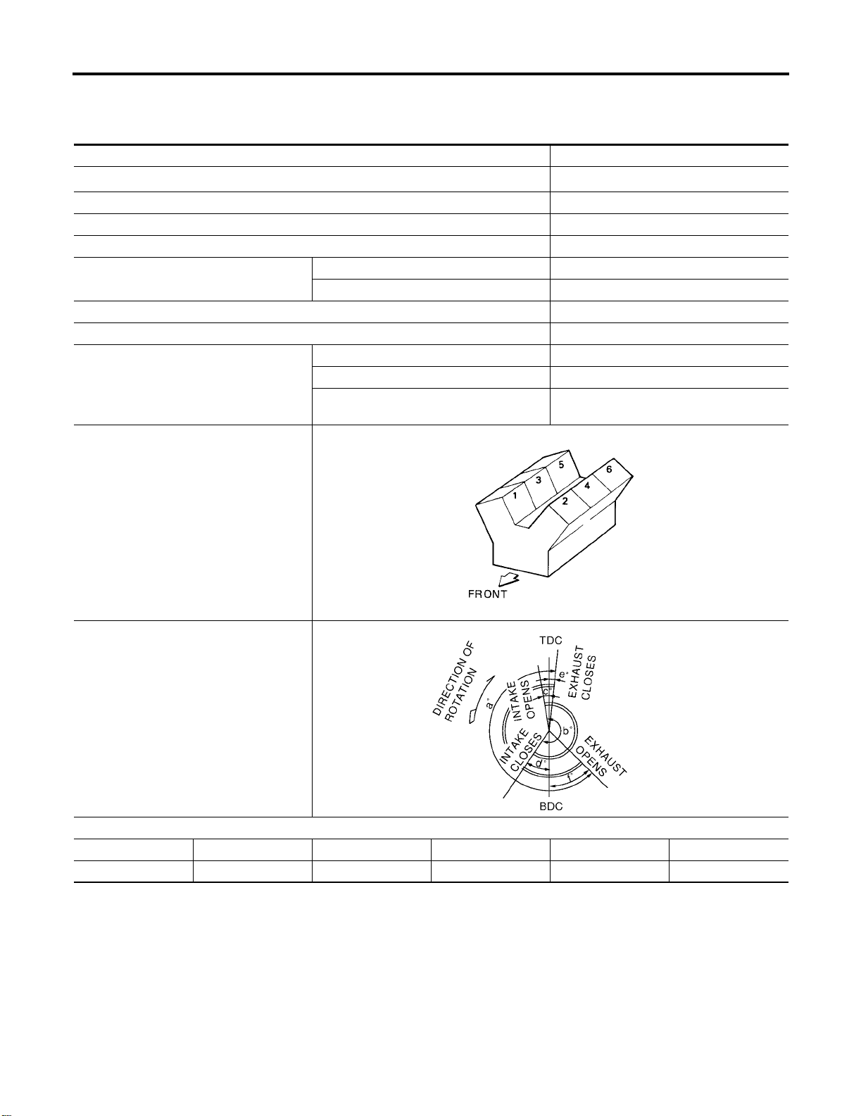
Valve timing (IVTC - OFF)
PBIC0187E
abcdef
240° 238° - 6° 64° 8° 52°
Unit: degree
Page 10
QUICK REFERENCE CHART: ALTIMA (EQUIPPED WITH
Drive Belt Deflection and Tension
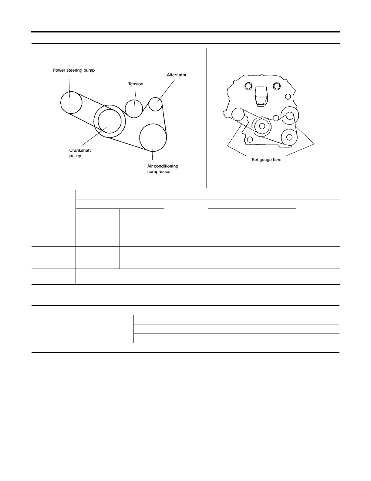
Deflection adjustment Unit: mm (in) Tension adjustment* Unit: N (kg, lb)
Used belt
Limit After adjustment Limit After adjustment
Alternator and
air conditioning
compressor
7 (0.28)
3.5L, VQ ENGINE)
4.2 - 4.6
(0.17 - 0.18)
New belt
3.7 - 4.1
(0.15 - 0. 16)
294 (30, 66)
Used belt
730 - 818
(74.5 - 83.5,
164 - 184)
2006
LBIA0076E
New belt
838 - 926
(85.5 - 94.5,
188 - 208)
Power steering
pump
Applied pushing
force
*: If belt tension gauge cannot be installed at check points shown , che ck dr iv e belt tensi on at different locat ion on th e bel t.
11 (0.43)
7.3 - 8
(0.29 - 0.30)
98 N (10 kg, 22 lb) —
6.5 - 7.2
(0.26 - 0. 28)
196 (20, 44)
495 - 583
(50.5 - 59.5,
111 - 131)
Spark Plugs (Double Platinum Tipped)
Make NGK
Standard PLFR5A-11
Type
Gap (nominal) 1.1 mm (0.043 in)
Hot PLFR4A-11
Cold PLFR6A-11
603 - 691
(61.5 - 70.5,
135.6 - 155.4)
Page 11

QUICK REFERENCE CHART: ALTIMA (EQUIPPED WITH
3.5L, VQ ENGINE)
2006
Front Wheel Alignmen t (Unladen*1)
Market United States and Canada Mexico
Engine VQ35DE VQ35DE
Model SL SE SE-R SE
Tire size 215/
60R16
Camber
Degree minute (Decimal degree)
Caster
Degree minute (Decimal degree)
Kingpin inclination
Degree minute (Decimal degree)
Total toe-in
Distance (A − B)
mm (in)
Angle (left, right)
Degree minute (Decimal
degree)
Wheel turning
angle
Full turn*2
*1: Fuel, engine coolant and engine oil full. Spare tire, jack, hand tools and mats in designat ed positions.
*2: On power steering m odels, wheel turning force (at circumferenc e of steering wheel) of 98 to 147 N (10 t o 15 kg, 22 to 33 l b) with
engine idle.
Inside
Degree minute (Decimal
degree)
Outside
Degree minute (Decimal
degree)
Minimum −1°00′ (−1.00°)-0°40′ (-0.67°)
Nominal −0°15′ (−0.25°)0°05′ (0.08°)
Maximum 0°30′ (0.50°)0°50′ (0.83°)
Left and right difference 45′ (0.75°) or less 45′ (0.75°) or l ess
Minimum 2°05′ (2.08°)1°55′ (1.92°)
Nominal 2°50′ (2.83°)2°40′ (2.67°)
Maximum 3°35′ (3.58°)3°25′ (3.42°)
Left and right difference 45′ (0.75°) or less 45′ (0.75°) or l ess
Minimum 13°50′ (13.83°)13°10′ (13.17°)
Nominal 14°35′ (14.58°)13°55′ (13.93°)
Maximum 15°20′ (15.33°)14°40′ (14.67°)
Minimum −0.5 (−0.02) 0.0 (0.00)
Nominal 0.5 (0.02) 1.0 (0.04)
Maximum 1.5 (0. 06) 2.0 (0.08)
Minimum −0°04′ (−0.07°) −0°03′ (−0.05°)
Nominal 0°02′ (0.03°)0°03′ (0.03°)
Maximum 0°08′ (0.13°)0°09′ (0.15°)
Minimum 32°00′ (32.0°)
Nominal 35°30′ (35.5°)
Maximum 36°30′ (36.5°)
Nominal 29°00′ (29.0°)
215/
55R17
225/
45R18
31°00′
(31.0°)
34°30′
(34.5°)
35°30′
(35.5°)
29°00′
(29.0°)
215/55R17
32°00′ (32.0°)
35°30′ (35.5°)
36°30′ (36.5°)
29°00′ (29.0°)
ELS001Q5
Page 12
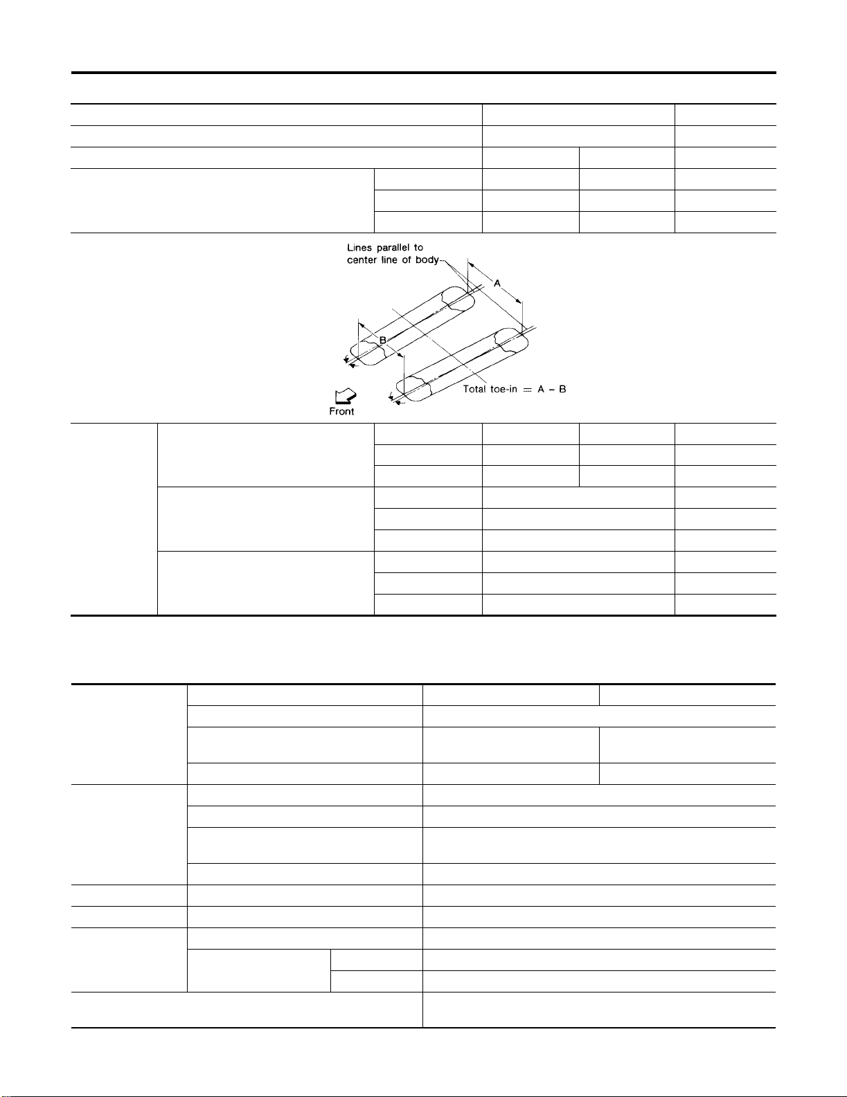
QUICK REFERENCE CHART: ALTIMA (EQUIPPED WITH
3.5L, VQ ENGINE)
2006
Rear Wheel Alignment (Unladen*)
Market United States and Canada Mexico
Engine VQ35DE VQ35DE
Model SL / SE SE-R SE
Minimum −0° 2' (−0.03°) −0° 13′ (−0.22°)-0° 30' (0.50°)
Camber
Degree minute (Decimal degree)
Distance (A − B)
mm (in)
Distance difference
Total toe-in
*: Fuel, engine coolant and engine oil full. Spare tire, jack, hand tools and mats in designat ed positions.
between RH and LH side
mm (in)
Angle (left plus right)
Degree minute (decimal degree)
Nominal −0° 32′ (−0.53°) −0° 43′ (−0.72°)0° 0' (0°)
Maximum −1° 2′ (−1.03°) −1° 13′ (−1.22°)0° 30' (0.50°)
SFA234AC
Minimum 2.4 (0.09) 2.3 (0.09) 1.3 (0.05)
Nominal 3.9 (0.15) 3.8 (0.15) 2.8 (0.11)
Maximum 5.4 (0.21) 5. 3 (0 .2 1) 4.3 (0.17)
Minimum −2 (−0.08) -2 (-0.08)
Nominal 0 (0) 0 (0)
Maximum 2 (0.08) 2 (0.08)
Minimum 0° 6′ (0.10°)0° 3' (0.05°)
Nominal 0° 10′ (0.17°)0° 7' ( 0.1 2°)
Maximum 0° 14′ (0.23°)0° 11' (0.18°)
ELS001Q6
Brake
Brake model CLZ25VD disc brake CLZ25VE disc brake
Cylinder bore diameter 57.2 (2.25)
Front brake
Rear brake
Master cylinder Cylinder bore diameter 23.81 (15/16)
Control valve Screw in type 30 × 0.4 (1.18 × 0.02)
Brake booster
Recommended brake fluid
Pad
Length × width × thickness
Rotor outer diameter × thickness 296 × 24 (11.7 × 0.94) 320 × 28 (12.6 × 1.10)
Brake model AD9A disc brake
Cylinder bore diameter 34.9 (1.3740)
Pad
Length × width × thickness
Rotor outer diameter × thickness 292 × 9 (11.5 × 0.35)
Booster model M215T
Diaphragm diameter
Primary 230 (9.06)
Secondary 205 (8.07)
125.6 × 46 × 11
(4.94 × 1.81 × 0.43)
89.1 × 39.5 × 10 (3.508 × 1.555 × 0.31)
Genuine NISSAN Super Heavy Duty Brake Fluid or equivalent
DOT 3 (US FMVSS No. 116)
ELS001Q7
Unit: mm (in)
111.0 × 62.5 × 9.5
(4.37 × 2.46 × 0.37)
Page 13
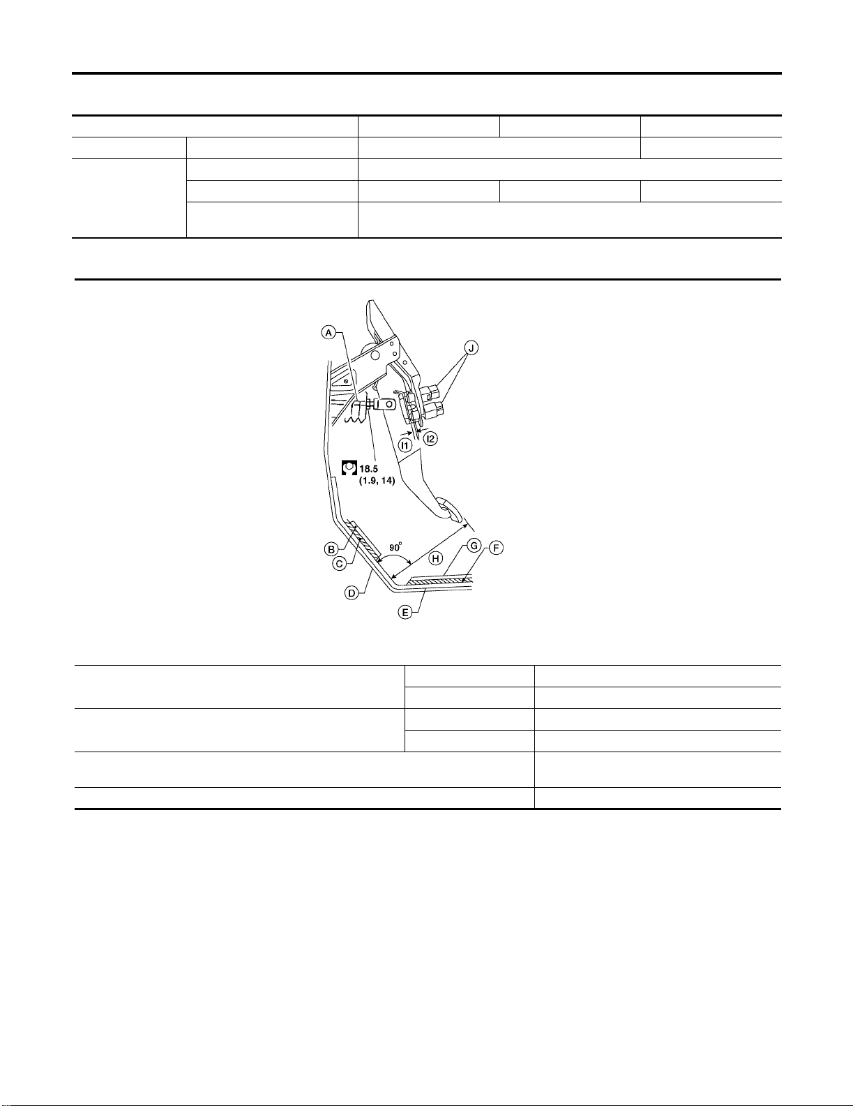
QUICK REFERENCE CHART: ALTIMA (EQUIPPED WITH
3.5L, VQ ENGINE)
Disc Brake - Repair Limits
Unit: mm (in)
Brake model CLZ25VD CLZ25VE AD9A
Pad wear limit Minimum thickness 2.0 (0.079) 1.5 (0.05 9)
Maximum runout 0.07 (0.0028)
Rotor repair limit
Brake Pedal
Minimum thickness 22.0 (0.866) 26.0 (1.02) 8.0 (0.31)
Maximum thickness variation
(at least 8 positions)
0.015 (0.0006)
Unit: mm (in)
2006
WFIA0423E
Free height “H”*
Pedal height (with engine running, brake pedal force 490 N
{50 kg-f, 110 lb-f) “H”
Clearance “I1” or “I2” between pedal stopper and threaded end of stop lamp switch or
ASCD switch
Pedal play 3 - 11 (0.12 - 0.43)
*: Measured from surface of dash reinforce me nt panel to surface of pedal pad
A: Input rod
B: Floor carpet
C: Dash Insulator
D: Floor Panel
E: Dash reinforcement panel
F: Dash insulator
G: Floor carpet
I1, I2: Gap
J: Stop lamp switch and ASCD switch
M/T 164.1 - 174.1 (6.46 - 6.85)
A/T 173.1 - 183.1 (6.81 - 7.21)
M/T More than 84 (3.31)
A/T More than 90.3 (3.55)
0.74 - 1.96 (0.0291 - 0.0772)
Page 14
QUICK REFERENCE CHART: ALTIMA (EQUIPPED WITH
3.5L, VQ ENGINE)
2006
Refill Capacities
Description
Fuel 75.6 20 gal 16 5/8 gal
Engine oil
Drain and refill
Dry engine (engine overhaul) 4.6 4 7/8 qt 4 qt
Cooling system With reservoir at MAX level 8.2 2 1/8 gal 1 3/4 gal
Manual transaxle fluid (MTF) 2.2 2 3/8 qt 2 qt
Automatic transaxle (5A/T) fluid (ATF) 7.3 7 3/4 qt 6 3/8 qt
Power steering fluid (PSF) 1.0 2 1/8 pt 1 3/4 pt
Air conditioning system refrigerant 0.50 ± 0.025 kg 1.10 ± 0.055 lb 1.10 ± 0.055 lb
Air conditioning system oil
With oil filter change 4.2 4 1/2 qt 3 3/4 qt
Without oil filter change 4.0 4 1/4 qt 3 1/2 qt
Liter US measure Imp me asur e
150 m
Capacity (Approximate)
5.03 fl oz 5.01 fl oz
ELS001Q8
Page 15

B ENGINE
A
ACC
SECTION
ACCELERATOR CONTROL SYSTEM
CONTENTS
PRECAUTIONS .......................................................... 2
Precautions for Supplemental Restraint System
(SRS) “AIR BAG” and “SEAT BELT PRE-TEN-
SIONER” .................................................................. 2
ACCELERATOR CONTROL SYSTEM .......................3
Removal and Installation .......................................... 3
REMOVAL ............................................................. 3
INSTALLATION .....................................................3
SERVICE DATA AND SPECIFICATIONS (SDS) ........5
Accelerator Control ...................................................5
PEDAL TRAVEL ....................................................5
C
D
E
F
G
H
I
J
K
M
L
Revision: July 2005 2006 Altima
ACC-1
Page 16

PRECAUTIONS
PRECAUTIONS PFP:00001
Precautions for Supplemental Restraint System (SRS) “AIR BAG” and “SEA T
BELT PRE-TENSIONER”
The Supplemental Restraint System such as “AIR BAG” and “SEAT BELT PRE-TENSIONER”, used along
with a front sea t belt , helps t o redu ce th e r isk or s everi ty of injury to th e driv er an d front passenge r for c ertain
types of collisi on . Thi s s ys te m in cludes seat belt swi tch inp uts an d dual stage front air bag mod ul es . The SRS
system uses the seat belt switches to determine the front air bag deployment, and may only deploy one front
air bag, depending on the severity of a collision and whether the front occupants are belted or unbelted.
Information ne ce ss ary t o se rvi ce th e sy stem saf e ly is i nclu de d in th e SR S and SB se ct i on of th is Ser vic e Manual.
WARNING:
● To avoid rendering the SRS inoperativ e, which could increase the risk of persona l injury or death
in the event of a collision which would result in air bag inflation, all maintenance must be performed by an authorized NISSAN/INFINITI dealer.
● Improper maintenance, in cluding incorrect removal a nd installation of the SRS, can lead to per-
sonal injury caused by unintentional activation of the system. For rem ova l of Sp iral Cable and Air
Bag Module, see the SRS section.
● Do not use electrical test equipme nt on any circuit related to the SRS unle ss instructed to in this
Service Manual. SRS wiring harnesses can be identified by yellow and/or orange harnesses or
harness connectors .
EBS00QUU
Revision: July 2005
ACC-2
2006 Altima
Page 17
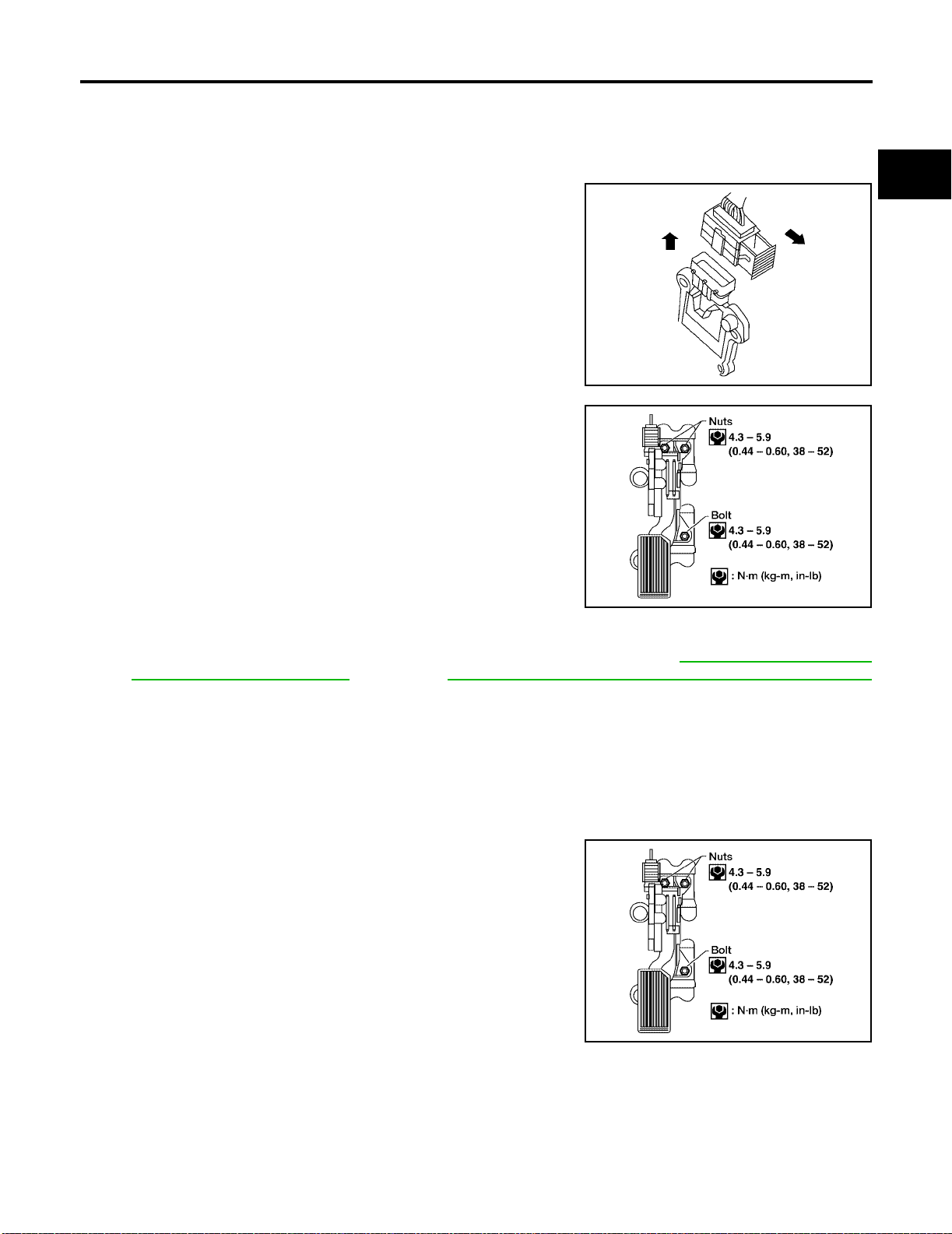
ACCELERATOR CONTROL SYSTEM
ACCELERATOR CONTROL SYSTEM PFP:18005
Removal and Installation
REMOVAL
1. Disco nnec t the ba tte ry ne ga tiv e term in al .
2. Disconnect the accelerator position sensor electrical connector.
a. Pull the connector lock back to unlock the connector from the
accelerator pedal position s ensor as shown.
b. Pull up on the connector to disconnect it from the accelerator
pedal position sensor as shown.
EBS00J8R
LBIA0333E
A
ACC
C
D
E
3. Remove the upper accelerator pedal nuts and lower accelerator
pedal bolt.
4. Remove the accelerator pedal and accelerator position sensor assembly.
● For electrical inspection of the accelerator pedal position sensor. Refer to EC-550, "ACCELERATOR
PEDAL POSITION SENSOR" (QR25DE), EC-1230, "ACCELERATOR PEDAL POSITION SENSOR"
(VQ35DE).
CAUTION:
● Do not disassemble the peda l assembly. Do not remove the accelerator pedal position sensor
from the pedal assembly.
● Avoid impact from dropping during handling.
● Keep the pedal assemb ly away from water.
INSTALLATION
Installation is in the reverse order of removal.
● Check the accele rator pedal for smooth ope ration. There should
be no binding o r st i cki ng w h en ap pl yi ng or r el ea si ng th e a cc eler ator pedal.
LBIA0334E
F
G
H
I
J
K
L
M
LBIA0334E
Revision: July 2005 2006 Altima
ACC-3
Page 18
ACCELERATOR CONTROL SYSTEM
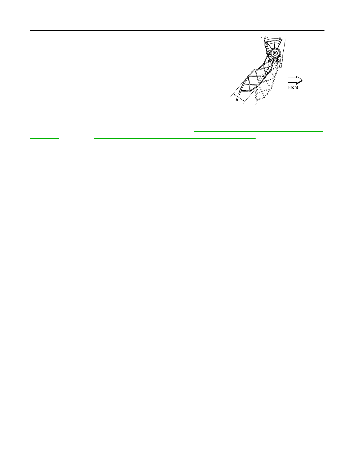
● Check that the accelerator pedal moves through the full speci-
fied distance of pedal travel.
Pedal travel “A” : 52.6 - 58.2 mm (2.07 - 2.29 in)
LBIA0062E
CAUTION:
When the harness conne ctor of the accelerator pedal position sensor i s disconnected, perform the
“Accelerator pedal released p osition learning” . Refer to EC-81, "
Learning" (QR25DE), EC-684, "Accelerator Pedal Released Position Learning" (VQ35DE).
Accelerator Pedal Released P osition
Revision: July 2005
ACC-4
2006 Altima
Page 19
SERVICE DATA AND SPECIFICATIONS (SDS)
SERVICE DATA AND SPECIFICATIONS (SDS) PFP:00030
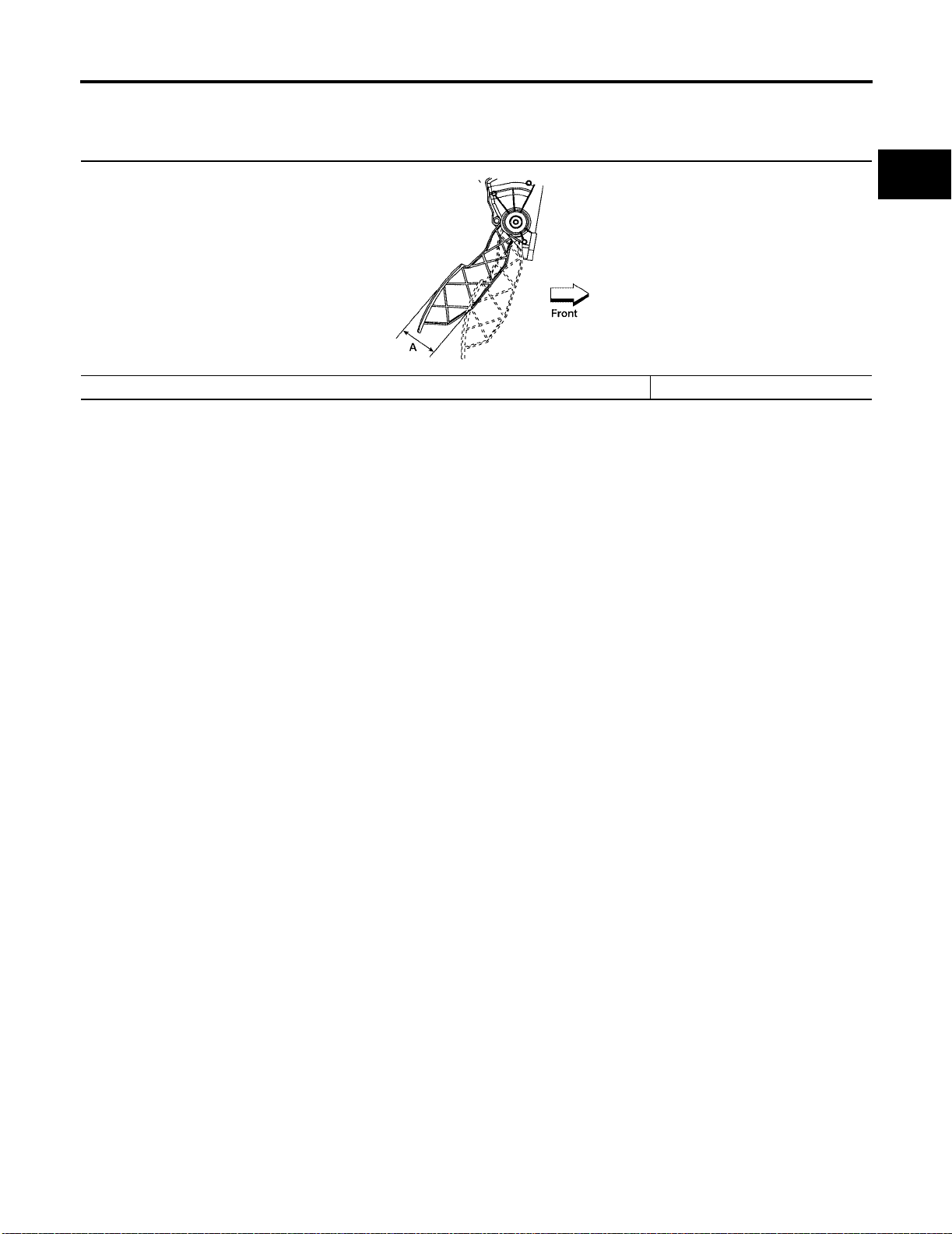
Accelerator Control
PEDAL TRAVEL
EBS00J8S
A
ACC
C
D
LBIA0062E
Accelerator pedal - total travel “A” 52.6 - 58.2 mm (2.07 - 2.29 in)
E
F
G
H
I
J
K
L
Revision: July 2005 2006 Altima
ACC-5
M
Page 20

SERVICE DATA AND SPECIFICATIONS (SDS)
Revision: July 2005
ACC-6
2006 Altima
Page 21
K ELECTRICAL
A
B
SECTION
AUTO CRUISE CONTROL SYSTEM
CONTENTS
AUTOMA TIC SPEED CONTROL DEVICE (ASCD) ..... 2
Description ............................................................... 2
C
D
E
F
G
H
I
J
ACS
L
M
Revision: July 2005 2006 Altima
ACS-1
Page 22

AUTOMATIC SPEED CONTROL DEVICE (ASCD)
AUTOMATIC SPEED CONTROL DEVICE (ASCD) PFP:18930
Description
Regarding the information for ASCD system, refer to EC-34, "AUTOMATIC SPEED CONTROL DEVICE
(ASCD)" (QR engine models), EC-635, "AUTOMATIC SPEED CONTROL DEVICE (ASCD)" (VQ engine
models).
EKS008U9
Revision: July 2005 2006 Altima
ACS-2
Page 23

C TRANSMISSION/TRANSAXLE
A
B
SECTION
CONTENTS
RE4F04B
TROUBLE DIAGNOSIS - INDEX ................................ 8
Alphabetical & P No. Index for DTC ......................... 8
PRECAUTIONS ........................................................ 10
Precautions for Supplemental Restraint System
(SRS) “AIR BAG” and “SEAT BELT PRE-TEN-
SIONER” ................................................................ 10
Precautions for On Board Diagnostic (OBD) System
of A/T and Engine .................................................. 10
Precautions ............................................................ 10
Service Notice or Precautions ................................ 12
PREPARATION ................. .................... ............. ....... 14
Special Service Tools ............................................. 14
Commercial Service Tools ...................................... 17
A/T FLUID ................................................................. 18
Changing A/T Fluid .. ...... ....... ...... ....... .................... 18
Checking A/T Fluid ................................................. 18
A/T Fluid Cooler Cleaning ...................................... 19
OVERALL SYSTEM ................................................. 23
A/T Electrical Parts Location .................................. 23
Circuit Diagram ...................................................... 24
Cross-sectional View .............................................. 25
Hydraulic Control Circuit ........................................ 26
Shift Mechanism ..................................................... 27
Control System ... ...... ...... ....... ...... ....... ...... ....... ....... 36
Control Mechanism ............... ...... ....... ...... ....... ....... 38
Control Valve ............ ...... ....... ...... ........................... 42
ON BOARD DIAGNOSTIC SYSTEM DESCRIP-
TION ............................ .......................... .................... 44
Introduction ............................................................ 44
OBD-II Function for A/T System ............................. 44
One or Two Trip Detection Logic of OBD-II ............ 44
OBD-II Diagnostic Trouble Code (DTC) ................. 44
Malfunction Indicator Lamp (MIL) ........................... 48
CONSULT-II Function (TCM) ................................. 48
Diagnostic Procedure Without CONSULT-II ........... 59
TROUBLE DIAGNOSIS - INTRODUCTION ............. 64
Introduction ............................................................ 64
Work Flow .............................................................. 68
AUTOMATIC TRANSAXLE
TROUBLE DIAGNOSIS - BASIC INSPECTION .......71
A/T Fluid Check ...................................................... 71
A/T Fluid Cooler Cleaning ......................................71
Stall Test ................................................................. 74
Line Pressure Test ..................................................77
Road Test ...............................................................78
TROUBLE DIAGNOSIS - GENERAL DESCRIP-
TION ..........................................................................93
Symptom Chart .......................................................93
TCM Terminals and Reference Value ...................103
CAN Communication ............................................106
TROUBLE DIAGNOSIS FOR POWER SUPPLY ....107
Wiring Diagram — AT — MAIN ............................107
Diagnostic Procedure ...........................................108
DTC P0705 P ARK/NEUTRAL POSITION SWITCH .110
Description ................... ...... ....... ...... ......................110
On Board Diagnosis Logic ....................................110
Possible Cause .....................................................110
Diagnostic Trouble Code (DTC) Confirmation Pro-
cedure .......................... ...... ....... ...... ....... ...... ....... ..110
Wiring Diagram — AT — PNP/SW .......................112
Diagnostic Procedure ...........................................113
DTC P0710 A/T FLUID TEMPERATURE SENSOR
CIRCUIT ..................................................................116
Description ................... ...... ....... ...... ......................116
On Board Diagnosis Logic ....................................116
Possible Cause .....................................................116
Diagnostic Trouble Code (DTC) Confirmation Pro-
cedure .......................... ...... ....... ...... ....... ...... ....... ..116
Wiring Diagram — AT — FTS ..............................118
Diagnostic Procedure ...........................................120
DTC P0720 VEHICLE SPEED SENSOR·A/T (REV-
OLUTION SENSOR) ...............................................122
Description ................... ...... ....... ...... ......................122
On Board Diagnosis Logic ....................................122
Possible Cause .....................................................122
Diagnostic Trouble Code (DTC) Confirmation Pro-
cedure .......................... ...... ....... ...... ....... ...... ....... ..122
Wiring Diagram — AT — VSSA/T ........................124
Diagnostic Procedure ...........................................125
AT
D
E
F
G
H
I
J
K
L
M
Revision: July 2005 2006 Altima
AT-1
Page 24

DTC P0725 ENGINE SPEED SIGNAL ...................127
Description ................ .......................... ..................127
On Board Diagnosis Logic ....................................127
Possible Cause .....................................................127
Diagnostic Trouble Code (DTC) Confirmation Pro-
cedure ....................... .......................... ..................127
Wiring Diagram — AT — ENGSS .........................128
Diagnostic Procedure ...........................................129
DTC P0731 A/T 1ST GEAR FUNCTION .................131
Description ................ .......................... ..................131
On Board Diagnosis Logic ....................................131
Possible Cause .....................................................131
Diagnostic Trouble Code (DTC) Confirmation Pro-
cedure ....................... .......................... ..................131
Wiring Diagram — AT — 1STSIG .........................133
Diagnostic Procedure ...........................................134
DTC P0732 A/T 2ND GEAR FUNCTION ................136
Description ................ .......................... ..................136
On Board Diagnosis Logic ....................................136
Possible Cause .....................................................136
Diagnostic Trouble Code (DTC) Confirmation Pro-
cedure ....................... .......................... ..................136
Wiring Diagram — AT — 2NDSIG ........................138
Diagnostic Procedure ...........................................139
DTC P0733 A/T 3RD GEAR FUNCTION ................141
Description ................ .......................... ..................141
On Board Diagnosis Logic ....................................141
Possible Cause .....................................................141
Diagnostic Trouble Code (DTC) Confirmation Pro-
cedure ....................... .......................... ..................141
Wiring Diagram — AT — 3RDSIG ........................143
Diagnostic Procedure ...........................................144
DTC P0734 A/T 4TH GEAR FUNCTION ................146
Description ................ .......................... ..................146
On Board Diagnosis Logic ....................................146
Possible Cause .....................................................146
Diagnostic Trouble Code (DTC) Confirmation Pro-
cedure ....................... .......................... ..................146
Wiring Diagram — AT — 4THSIG ........................148
Diagnostic Procedure ...........................................149
DTC P0740 TORQUE CONVERTER CLUTCH
SOLENOID VALVE ............................... ...... ....... .....153
Description ................ .......................... ..................153
On Board Diagnosis Logic ....................................153
Possible Cause .....................................................153
Diagnostic Trouble Code (DTC) Confirmation Pro-
cedure ....................... .......................... ..................153
Wiring Diagram — AT — TCV ..............................155
Diagnostic Procedure ...........................................156
DTC P0744 A/T TCC S/V FUNCTION (LOCK-UP) .158
Description ................ .......................... ..................158
On Board Diagnosis Logic ....................................158
Possible Cause .....................................................158
Diagnostic Trouble Code (DTC) Confirmation Pro-
cedure ....................... .......................... ..................158
Wiring Diagram — AT — TCCSIG ........................160
Diagnostic Procedure ...........................................161
DTC P0745 LINE PRE SSU RE SO LENO ID VALVE .166
Description ................ .......................... ..................166
On Board Diagnosis Logic ....................................166
Possible Cause .....................................................166
Diagnostic Trouble Code (DTC) Confirmation Pro-
cedure ...................................................................166
Wiring Diagram — AT — LPSV ............................168
Diagnostic Procedure ............................................169
DTC P0750 SHIFT SOLENOID VALVE A ...............172
Description ............................................................172
On Board Diagnosis Logic ....................................172
Possible Cause .....................................................172
Diagnostic Trouble Code (DTC) Confirmation Pro-
cedure ...................................................................172
Wiring Diagram — AT — SSV/A ...........................174
Diagnostic Procedure ............................................175
DTC P0755 SHIFT SOLENOID VALVE B ...............177
Description ............................................................177
On Board Diagnosis Logic ....................................177
Possible Cause .....................................................177
Diagnostic Trouble Code (DTC) Confirmation Pro-
cedure ...................................................................177
Wiring Diagram — AT — SSV/B ...........................179
Diagnostic Procedure ............................................180
DTC P1705 THROTTLE POSITION SENSOR
[ACCELERATOR PEDAL POSITION (APP) SEN-
SOR] ........................................................................182
Description ............................................................182
On Board Diagnosis Logic ....................................182
Possible Cause .....................................................182
Diagnostic Trouble Code (DTC) Confirmation Pro-
cedure ...................................................................182
Diagnostic Procedure ............................................183
DTC P1760 OVERRUN CLUTCH SOLENOID
VALVE .................................................................... ..185
Description ............................................................185
On Board Diagnosis Logic ....................................185
Possible Cause .....................................................185
Diagnostic Trouble Code (DTC) Confirmation Pro-
cedure ...................................................................185
Wiring Diagram — AT — OVRCSV ......................187
Diagnostic Procedure ............................................188
DTC U1000 CAN COMMUNICATION LINE ............190
Description ............................................................190
On Board Diagnosis Logic ....................................190
Possible Cause .....................................................190
DTC Confirmation Procedure ................................190
Wiring Diagram — AT — CAN ..............................192
Diagnostic Procedure ............................................193
DTC BATT/FLUID TEMP SEN (A/T FLUID TEMP
SENSOR CIRCUIT AND TCM POWER SOURCE) .194
Description ............................................................194
On Board Diagnosis Logic ....................................194
Possible Cause .....................................................194
Diagnostic Trouble Code (DTC) Confirmation Pro-
cedure ...................................................................194
Wiring Diagram — AT — BA/FTS .........................196
Diagnostic Procedure ............................................197
DTC VEHICLE SPEED SENSOR MTR ...................201
Description ............................................................201
On Board Diagnosis Logic ....................................201
Revision: July 2005 2006 Altima
AT-2
Page 25

Possible Cause .................................................... 201
Diagnostic Trouble Code (DTC) Confirmation Pro-
cedure .................................................................. 201
Wiring Diagram — AT — VSSMTR ...................... 203
Diagnostic Procedure ........................................... 204
DTC TURBINE REVOLUTION SENSOR ............... 205
Description ........................................................... 205
Wiring Diagram — AT — TRSA/T ........................ 206
Diagnostic Procedure ........................................... 207
Component Inspection ......................................... 208
DTC CONTROL UNIT (RAM), CONTROL UNIT
(ROM) ..................................................................... 209
Description ........................................................... 209
On Board Diagnosis Logic ................................... 209
Possible Cause .................................................... 209
Diagnostic Trouble Code (DTC) Confirmation Pro-
cedure .................................................................. 209
Diagnostic Procedure ........................................... 210
DTC CONTROL UNIT (EEP ROM) ..........................211
Description ............................................................211
Diagnostic Procedure ........................................... 212
TROUBLE DIAGNOSIS FOR SYMPTOMS ............ 213
Wiring Diagram — AT — NONDTC ...................... 213
1. A/T Check (Position) Indicator Lamp Does Not
Come On .............................................................. 217
2. Engine Cannot Be Started In P and N Position . 219
3. In P Position, Vehicle Moves Forward or Back-
ward When Pushed ............... ...... ....... ...... ....... ..... 220
4. In N Position, Vehicle Moves ............................ 221
5. Large Shock. N → R Position .......................... 223
6. Vehicle Does Not Creep Backward In R Position . 225
7. Vehicle Does Not Creep Forward in D, 3, 2 or 1
Position ................................................................ 228
8. Vehicle Cannot Be Started From D
9. A/T Does Not Shift: D
down: D
4 → D2 ............................ ......................... 234
10. A/T Does Not Shift: D
11. A/T Does Not Shift: D
1 → D2 or Does Not Kick-
2 → D3 ......................... 237
3 → D4 ..................... ..... 240
1 ................. 231
12. A/T Does Not Perform Lock-up ...................... 243
13. A/T Does Not Hold Lock-up Condition ........... 245
14. Lock-up Is Not Released ................................ 247
15. Engine Speed Does Not Return To Idle (Light
Braking D
16. Vehicle Does Not Start From D
17. A/T Does Not Shift: D
4 → D3 ) ....................... ......................... 248
1 ..................... 250
4 → 33 , When A/T Selector
Lever D → 3 ......................................................... 251
18. A/T Does Not Shift: 3
3 → 22 , When Selector
Lever 3 → 2 Position ............................................ 252
19. A/T Does Not Shift: 2
2 → 11 , When Selector
Lever 2 → 1 Position ............................................ 253
20. Vehicle Does Not Decelerate By Engine Brake . 254
21. TCM Self-diagnosis Does Not Activate (PNP &
3 Position Switches Circuit Checks), and Throttle
Position Sensor [Accelerator Pedal Position (APP)
Sensor] Circuit Check .......................................... 254
A/T SHIFT LOCK SYSTEM .................................... 260
Description ........................................................... 260
Shift Lock System Electrical Parts Location ......... 260
Wiring Diagram — SHIFT — ................................ 261
Shift Lock Control Unit Reference Values ............262
Component Inspection ..........................................263
SHIFT CONTROL SYSTEM ....................................265
Control Device ......................................................265
Control Cable ........................................................266
ON-VEHICLE SERVICE ..........................................267
Control Valve Assembly and Accumulators ..........267
Revolution Sensor Replacement ..........................269
Turbine Revolution Sensor Replacement .............269
Park/Neutral Position (PNP) Switch Adjustment ..269
Control Cable Adjustment .....................................270
Differential Side Oil Seal Replacement ................270
AIR BREATHER HOSE ..........................................272
Air Breather Hose - Air Duct Side .........................272
Air Breather Hose - Transaxle Side ......................273
REMOVAL AND INSTALLATION ...........................275
Removal ...............................................................275
Inspection .............................................................276
Installation ............................................................277
OVERHAUL ............................................................278
Components .........................................................278
Oil Channel ...........................................................281
Locations of Adjusting Shims, Needle Bearings,
Thrust Washers and Snap Rings ..........................282
DISASSEMBLY .......................................................283
Disassembly .........................................................283
REPAIR FOR COMPONENT PARTS .....................299
Manual Shaft ........................................................299
Oil Pump ...............................................................302
Control Valve Assembly ........................................306
Control Valve Upper Body ....................................315
Control Valve Lower Body ....................................319
Reverse Clutch .....................................................321
High Clutch ..... ....................................... ...... ....... ..324
Forward and Overrun Clutches ............................328
Low & Reverse Brake ...........................................334
Rear Internal Gear, Forward Clutch Hub and Over-
run Clutch Hub .......................... ...... ....... ...... ....... ..337
Output Shaft, Idler Gear, Reduction Pinion Gear and
Bearing Retainer ...................................................341
Band Servo Piston Assembly ...............................346
Final Drive ............................................................351
ASSEMBLY ................................. ............................356
Assembly (1) .........................................................356
Adjustment (1) ......................................................357
Assembly (2) .........................................................362
Adjustment (2) ......................................................369
Assembly (3) .........................................................371
SERVICE DATA AND SPECIFICATIONS (SDS) ....378
General Specifications . ...... ....... ...... ......................378
Shift Schedule ......................................................378
Stall Revolution .....................................................378
Line Pressure .......................................................379
Control Valves ......................................................379
Accumulator ................. ...... ....... ............................379
Clutch and Brakes ................................................380
Final Drive ............................................................382
Planetary Carrier and Oil Pump ...... ....... ...... ....... ..382
Input Shaft ............................................. ...... .........383
A
B
AT
D
E
F
G
H
I
J
K
L
M
Revision: July 2005 2006 Altima
AT-3
Page 26

Reduction Pinion Gear .........................................383
Band Servo ...........................................................384
Output Shaft .........................................................384
Bearing Retainer ...................................................385
Total End Play .......................................................385
Reverse Clutch End Play ......................................385
Removal and Installation ......................................385
Shift Solenoid Valves ............................................385
Solenoid Valves .. ...... ...... ....... ...... ....... ...... ....... .....385
A/T Fluid Temperature Sensor ..............................386
Revolution Sensor ................................................386
Dropping Resistor .................................................386
Turbine Revolution Sensor (Power Train Revolution
Sensor) .................................................................386
RE5F22A
INDEX FOR DTC .....................................................387
Alphabetical Index ................................................387
DTC No. Index ................ ....... ...... ....... ...... ....... .....388
PRECAUTIONS ........................ ...... ....... ...... ....... .....389
Precautions for Supplemental Restraint System
(SRS) “AIR BAG” and “SEAT BELT PRE-TEN-
SIONER” ................... .......................... ..................389
Precautions for On Board Diagnostic (OBD) System
of A/T and Engine .................................................389
Precautions for A/T Assembly or TCM Replacement .390
Precautions ............... .......................... ..................391
Service Notice or Precautions ..............................393
PREPARATION .......................................................394
Special Service Tools ...................................... .....394
Commercial Service Tools .................. ..................397
A/T FLUID ...............................................................398
Changing A/T Fluid ...............................................398
Checking A/T Fluid ...................... ....... ...... ....... .....398
A/T Fluid Cooler Cleaning ....................................399
A/T CONTROL SYSTEM ........................................403
Cross-Sectional View ............................................403
Shift Mechanism ...................................................404
TCM Function .......................................................421
Input/Output Signal of TCM ..................................422
CAN Communication ............................................422
Line Pressure Control ...........................................423
Shift Control ..........................................................423
Lock-Up Control .. ...... ...... ....... ...... ....... ...... ....... .....425
ON BOARD DIAGNOSTIC (OBD) SYSTEM ..........427
Introduction ............... ............................................427
OBD-II Function for A/T System ...........................427
One or Two Trip Detection Logic of OBD-II ..........427
OBD-II Diagnostic Trouble Code (DTC) ...............427
Malfunction Indicator Lamp (MIL) .........................430
TROUBLE DIAGNOSIS ..........................................431
DTC Inspection Priority Chart ...............................431
Fail-Safe ...............................................................431
How T o Perform Trouble Diagnosis For Quick and
Accurate Repair ....................................................434
A/T Electrical Parts Location .................................439
Circuit Diagram .....................................................440
Inspections Before Trouble Diagnosis ..................441
Check Before Engine is Started ............. ...............445
Check at Idle ... ....................................... ...... ....... ..445
Cruise Test - Part 1 ...............................................447
Cruise Test - Part 2 ...............................................448
Cruise Test - Part 3 ...............................................449
Shift Schedule .......................................................450
Symptom Chart .....................................................451
TCM Input/Output Signal Reference Values .........459
CONSULT-II Function (TCM) ................................462
Diagnostic Procedure Without CONSULT-II .........468
DTC U1000 CAN COMMUNICATION LINE ............471
Description ............................................................471
On Board Diagnosis Logic ....................................471
Possible Cause .....................................................471
DTC Confirmation Procedure ................................471
Wiring Diagram — AT — CAN ..............................472
Diagnostic Procedure ............................................473
DTC P0500 VEHICLE SPEED SENSOR MTR .......474
Description ............................................................474
On Board Diagnosis Logic ....................................474
Possible Cause .....................................................474
DTC Confirmation Procedure ................................474
Diagnostic Procedure ............................................475
DTC P0613 TCM PROCESSOR .............................476
Description ............................................................476
On Board Diagnosis Logic ....................................476
Possible Cause .....................................................476
DTC Confirmation Procedure ................................476
Diagnostic Procedure ............................................477
DTC P0705 PARK/NEUTRAL POSITION SWIT CH .478
Description ............................................................478
On Board Diagnosis Logic ....................................478
Possible Cause .....................................................478
DTC Confirmation Procedure ................................478
Wiring Diagram — AT — PNP/SW .......................479
Diagnostic Procedure ............................................480
Component Inspection ..........................................482
DTC P0710 A/T FLUID TEMPERATURE SENSOR
CIRCUIT ..................................................................483
Description ............................................................483
On Board Diagnosis Logic ....................................483
Possible Cause .....................................................483
DTC Confirmation Procedure ................................483
Wiring Diagram — AT — FTS ...............................484
Diagnostic Procedure ............................................485
Component Inspection ..........................................487
DTC P0711 FL UID TEMPERA TURE SENSOR PER-
FORMANCE ............................................................488
Description ............................................................488
On Board Diagnosis Logic ....................................488
Possible Cause .....................................................488
DTC Confirmation Procedure ................................488
Wiring Diagram — AT — FTSP ............................489
Diagnostic Procedure ............................................490
Component Inspection ..........................................492
DTC P0717 TURBINE REVOLUTION SENSOR CIR-
CUIT ...................................... .......................... .........493
Description ............................................................493
On Board Diagnosis Logic ....................................493
Revision: July 2005 2006 Altima
AT-4
Page 27

Possible Cause .................................................... 493
DTC Confirmation Procedure ............................... 493
Wiring Diagram — AT — TRSC ........................... 494
Diagnostic Procedure ........................................... 495
Component Inspection ......................................... 496
DTC P0722 VEHICLE SPEED SENSOR A/T (REV-
OLUTION SENSOR) CIRCUIT ............................... 497
Description ........................................................... 497
On Board Diagnosis Logic ................................... 497
Possible Cause .................................................... 497
DTC Confirmation Procedure ............................... 497
Wiring Diagram — AT — VSSATC ....................... 498
Diagnostic Procedure ........................................... 499
Component Inspection ......................................... 500
DTC P0726 ENGINE SPEED INPUT CIRCUIT PER-
FORMANCE ........................................................... 501
Description ........................................................... 501
On Board Diagnosis Logic ................................... 501
Possible Cause .................................................... 501
DTC Confirmation Procedure ............................... 501
Diagnostic Procedure ........................................... 501
DTC P0731 A/T 1ST GEAR FUNCTION ................ 503
Description ........................................................... 503
On Board Diagnosis Logic ................................... 503
Possible Cause .................................................... 503
DTC Confirmation Procedure ............................... 503
Wiring Diagram — AT — 1STSIG ........................ 504
Diagnostic Procedure ........................................... 505
DTC P0732 A/T 2ND GEAR FUNCTION ................ 506
Description ........................................................... 506
On Board Diagnosis Logic ................................... 506
Possible Cause .................................................... 506
DTC Confirmation Procedure ............................... 506
Wiring Diagram — AT — 2NDSIG ........................ 508
Diagnostic Procedure ........................................... 510
DTC P0733 A/T 3RD GEAR FUNCTION ................ 512
Description ........................................................... 512
On Board Diagnosis Logic ................................... 512
Possible Cause .................................................... 512
DTC Confirmation Procedure ............................... 512
Wiring Diagram — AT — 3RDSIG ........................ 514
Diagnostic Procedure ........................................... 516
DTC P0734 A/T 4TH GEAR FUNCTION ................ 518
Description ........................................................... 518
On Board Diagnosis Logic ................................... 518
Possible Cause .................................................... 518
DTC Confirmation Procedure ............................... 518
Wiring Diagram — AT — 4THSIG ........................ 520
Diagnostic Procedure ........................................... 521
DTC P0735 A/T 5TH GEAR FUNCTION ................ 523
Description ........................................................... 523
On Board Diagnosis Logic ................................... 523
Possible Cause .................................................... 523
DTC Confirmation Procedure ............................... 523
Wiring Diagram — AT — 5THSIG ........................ 525
Diagnostic Procedure ........................................... 527
DTC P0744 A/T TCC S/V FUNCTION (LOCK-UP) . 529
Description ........................................................... 529
On Board Diagnosis Logic ................................... 529
Possible Cause .....................................................529
DTC Confirmation Procedure ...............................529
Wiring Diagram — AT — TCCSIG ........................530
Diagnostic Procedure ...........................................531
DTC P0745 PRESSURE CONTROL SOLENOID
VALVE A (LINE PRESSURE) .................................532
Description ................... ...... ....... ...... ......................532
On Board Diagnosis Logic ....................................532
Possible Cause .....................................................532
DTC Confirmation Procedure ...............................532
Wiring Diagram — AT — PC/A .............................533
Diagnostic Procedure ...........................................534
Component Inspection ..........................................536
DTC P0750 SHIFT SOLENOID VALVE A ...............537
Description ................... ...... ....... ...... ......................537
On Board Diagnosis Logic ....................................537
Possible Cause .....................................................537
DTC Confirmation Procedure ...............................537
Wiring Diagram — AT — SSV/A ...........................538
Diagnostic Procedure ...........................................539
Component Inspection ..........................................541
DTC P0755 SHIFT SOLENOID VALVE B ...............542
Description ................... ...... ....... ...... ......................542
On Board Diagnosis Logic ....................................542
Possible Cause .....................................................542
DTC Confirmation Procedure ...............................542
Wiring Diagram — AT — SSV/B ...........................543
Diagnostic Procedure ...........................................544
Component Inspection ..........................................546
DTC P0760 SHIFT SOLENOID VALVE C ...............547
Description ................... ...... ....... ...... ......................547
On Board Diagnosis Logic ....................................547
Possible Cause .....................................................547
DTC Confirmation Procedure ...............................547
Wiring Diagram — AT — SSV/C ..........................548
Diagnostic Procedure ...........................................549
Component Inspection ..........................................551
DTC P0762 SHIFT SOLENOID VALVE C STUCK ON .552
Description ................... ...... ....... ...... ......................552
On Board Diagnosis Logic ....................................552
Possible Cause .....................................................552
DTC Confirmation Procedure ...............................552
Wiring Diagram — AT — SSV/CS ........................553
Diagnostic Procedure ...........................................554
Component Inspection ..........................................556
DTC P0765 SHIFT SOLENOID VALVE D ...............557
Description ................... ...... ....... ...... ......................557
On Board Diagnosis Logic ....................................557
Possible Cause .....................................................557
DTC Confirmation Procedure ...............................557
Wiring Diagram — AT — SSV/D ..........................558
Diagnostic Procedure ...........................................559
Component Inspection ..........................................561
DTC P0770 SHIFT SOLENOID VALVE E ...............562
Description ................... ...... ....... ...... ......................562
On Board Diagnosis Logic ....................................562
Possible Cause .....................................................562
DTC Confirmation Procedure ...............................562
Wiring Diagram — AT — SSV/E ...........................563
A
B
AT
D
E
F
G
H
I
J
K
L
M
Revision: July 2005 2006 Altima
AT-5
Page 28

Diagnostic Procedure ...........................................564
Component Inspection ..........................................566
DTC P0775 PRESSURE CONTROL SOLENOID
VALVE B (SHIFT PRESSURE) ...............................567
Description ................ .......................... ..................567
On Board Diagnosis Logic ....................................567
Possible Cause .....................................................567
DTC Confirmation Procedure ...............................567
Wiring Diagram — AT — PC/B .............................568
Diagnostic Procedure ...........................................569
Component Inspection ..........................................571
DTC P0780 SHIFT ...................................................572
Description ................ .......................... ..................572
On Board Diagnosis Logic ....................................572
Possible Cause .....................................................572
DTC Confirmation Procedure ...............................572
Wiring Diagram — AT — SFTFNC .......................573
Diagnostic Procedure ...........................................575
DTC P0795 PRESSURE CONTROL SOLENOID
VALVE C (TCC AND SHIFT PRESSURE) ..............576
Description ................ .......................... ..................576
On Board Diagnosis Logic ....................................576
Possible Cause .....................................................576
DTC Confirmation Procedure ...............................576
Wiring Diagram — AT — PC/C .............................577
Diagnostic Procedure ...........................................578
Component Inspection ..........................................580
DTC P0797 PRESSURE CONTROL SOLENOID
VALVE C STUCK ON ..............................................581
Description ................ .......................... ..................581
On Board Diagnosis Logic ....................................581
Possible Cause .....................................................581
DTC Confirmation Procedure ...............................581
Wiring Diagram — AT — PC/CS ..........................582
Diagnostic Procedure ...........................................583
Component Inspection ..........................................585
DTC P0826 MANUAL MODE SWITCH CIRCUIT ...586
Description ................ .......................... ..................586
CONSULT-II Reference Value in Data Monitor Mode
.586
On Board Diagnosis Logic ....................................586
Possible Cause .....................................................586
DTC Confirmation Procedure ...............................586
Wiring Diagram — AT — MMSW ..........................587
Diagnostic Procedure ...........................................589
Component Inspection ..........................................591
Position Indicator ..................................................591
DTC P0882 TCM POWER INPUT SIGNAL ............592
Description ................ .......................... ..................592
On Board Diagnosis Logic ....................................592
Possible Cause .....................................................592
DTC Confirmation Procedure ...............................592
Wiring Diagram — AT — PWR/IN ........................593
Diagnostic Procedure ...........................................595
Component Inspection ..........................................596
DTC P1726 ELECTRIC THROTTLE CONTROL
SYSTEM ............................ ......................................597
Description ................ .......................... ..................597
TROUBLE DIAGNOSIS FOR SYMPTOMS ............598
A/T CHECK Indicator Lamp does not come on ....598
Engine Cannot Be Started In “P” or “N” Position ...600
In “P” Position, Vehicle Moves When Pushed .......600
In “N” Position, Vehicle Moves ..............................601
Large Shock (“N” to “D” Position) ..........................602
Vehicle Does Not Creep Backward In “R” Position .603
Vehicle Does Not Creep Forward In “D” Position ..604
Vehicle Cannot Be Started From D
A/T Does Not Shift: D
A/T Does Not Shift: D
A/T Does Not Shift: D
A/T Does Not Shift: D
1 → D2 ................................605
2 → D3 ................................606
3 → D4 ................................607
4 → D5 ................................608
1 .....................605
A/T Does Not Perform Lock-up .............................609
A/T Does Not Hold Lock-up Condition ..................610
Lock-up Is Not Released .......................................611
Cannot Be Changed to Manual Mode ...................612
A/T Does Not Shift: 5th gear → 4th gear ..............613
A/T Does Not Shift: 4th gear → 3rd gear ..............614
A/T Does Not Shift: 3rd gear → 2nd gear .............614
A/T Does Not Shift: 2nd gear → 1st gear .............615
Vehicle Does Not Decelerate By Engine Brake ....616
TCM Self-diagnosis Does Not Activate .................617
SHIFT CONTROL SYSTEM ....................................619
Control Device ......................................................619
Control Cable ........................................................620
A/T SHIFT LOCK SYSTEM .....................................621
Description ............................................................621
Shift Lock System Electrical Parts Location ..........621
Wiring Diagram — AT — SHIFT ...........................622
Shift Lock Control Unit Reference Values .............623
Component Inspection ..........................................624
ON-VEHICLE SERVICE ..........................................626
Revolution Sensor Replacement ..........................626
Turbine Revolution Sensor Replacement .............626
Park/Neutral Position (PNP) Switch Adjustment ...626
ATF Cooler ............................................................627
ATF Cooler Valve ..................................................627
Control Cable Adjustment .....................................628
Side cover .............................................................629
Control Valve Assembly ........................................629
Terminal Cord Assembly .......................................629
REMOVAL AND INSTALLATION ............................631
Removal ............................. ...................................631
Inspection After Removal ......................................631
Installation .......................... ...................................632
OVERHAUL ................................. ............................634
Components ....................... .................... ...............634
Locations of Needle Bearings, Bearing Races and
Thrust Washers .................. ....... ...... ....... ...... ....... ..642
DISASSEMBLY .......................................................643
Disassembly ....................... ....... ............. ............. ..643
REPAIR FOR COMPONENT PARTS ......................662
Oil Pump, 2nd Coast Brake & 2nd Brake ..............662
One-Way Clutch Outer Race Sub Assembly & 2nd
Coast Brake Hub & One-Way Clutch No.1 ...........668
Transaxle Case Cover & B5 Brake .......................670
Differential Gear Assembly ...................................675
Revision: July 2005 2006 Altima
AT-6
Page 29

ASSEMBLY ............................................................. 678
Assembly (1) ........................................................ 678
Adjustment ........................................................... 685
Assembly (2) ........................................................ 686
SERVICE DATA AND SPECIFICATIONS (SDS) .... 702
General Specifications ......................................... 702
Shift Schedule ...................................................... 702
Stall Speed ........................................................... 703
Line Pressure ....................................................... 704
Time Lag ...............................................................704
Shift Solenoid Valves ............................................704
Solenoid Valves ....................................................704
Clutch and Brakes ................................................705
Final Drive ............................................................707
A/T Fluid Temperature Sensor ..............................708
Turbine Revolution Sensor ...................................708
Revolution Sensor ................................................708
A
B
AT
D
E
F
G
H
K
M
I
J
L
Revision: July 2005 2006 Altima
AT-7
Page 30
TROUBLE DIAGNOSIS - INDEX
[RE4F04B]
TROUBLE DIAGNOSIS - INDEX PFP:00000
Alphabetical & P No. Index for DTC
ECS0095J
NOTE:
If DTC U1000 is displayed with other DTC, first perform the trouble diagnosis for DTC U1000. Refer to
AT-190, "
DTC U1000 CAN COMMUNICATION LINE"
ALPHABETICAL INDEX FOR DTC
Items
(CONSULT- II scr een t erms)
A/T 1ST GR FNCTN P0731 AT-131
A/T 2ND GR FNCTN P0732 AT-136
A/T 3RD GR FNCTN P0733 AT-141
A/T 4TH GR FNCTN P0734 AT-146
A/T TCC S/V FNCTN P0744 AT-158
ATF TEMP SEN/CIRC P0710 AT-116
ENGINE SPEED SIG P0725 AT-127
L/PRESS SOL/CIRC P0745 AT-166
O/R CLTCH SOL/CIRC P1760 AT-185
PNP SW/CIRC P0705 AT-110
SFT SOL A/CIRC*2 P0750 AT-172
SFT SOL B/CIRC*2 P0755 AT-177
TCC SOLENOID/CIRC P0740 AT-153
THROTTLE POSI SEN*2 P1705 AT-182
VEH SPD SEN/CIR AT*3 P0720 AT-122
CAN COMM CIRCUIT U1000 AT-190
*1: These numbers are prescribed by SAE J2012.
*2: When the fail-safe operation occurs, th e MIL ill um in ate s.
*3: The MIL illuminates when bot h the “Revolution sens or signal” and the “Vehicle speed sensor si gnal” meet the fail-safe condi tion at
the same time.
DTC
CONSULT-II
GST*1
Reference page
Revision: July 2005 2006 Altima
AT-8
Page 31
TROUBLE DIAGNOSIS - INDEX
[RE4F04B]
P NO. INDEX FOR DTC
DTC
CONSULT-II
GST*1
P0705 PNP SW/CIRC AT-110
P0710 ATF TEMP SEN/CIRC AT-116
P0720 VEH SPD SEN/CIR AT*3 AT-122
P0725 ENGINE SPEED SIG AT-127
P0731 A/T 1ST GR FNCTN AT-131
P0732 A/T 2ND GR FNCTN AT-136
P0733 A/T 3RD GR FNCTN AT-141
P0734 A/T 4TH GR FNCTN AT-146
P0740 TCC SOLENOID/CIRC AT-153
P0744 A/T TCC S/V FNCTN AT-158
P0745 L/PRESS SOL/CIRC AT-166
P0750 SFT SOL A/CIRC*2 AT-172
P0755 SFT SOL B/CIRC*2 AT-177
P1705 THROTTLE POSI SEN*2 AT-182
P1760 O/R CLTCH SOL/CIRC AT-185
U1000 CAN COMM CIRCUIT AT-190
*1: These numbers are prescribed by SAE J2012.
*2: When the fail-safe operation occurs, the MIL illuminates.
*3: The MIL illuminates when both the “Rev olution sensor sign al” and the “Vehicle speed sensor signal” meet the fail-safe condi tion at
the same time.
(CONSULT-II screen terms)
Items
Reference page
A
B
AT
D
E
F
G
H
I
K
M
J
L
Revision: July 2005 2006 Altima
AT-9
Page 32
PRECAUTIONS
[RE4F04B]
PRECAUTIONS PFP:00001
Precautions for Supplemental Restraint System (SRS) “AIR BAG” and “SEA T
BELT PRE-TENSIONER”
The Supplemental Restraint System such as “AIR BAG” and “SEAT BELT PRE-TENSIONER”, used along
with a front sea t belt , helps t o redu ce th e r isk or s everi ty of injury to th e driv er an d front passenge r for c ertain
types of collisi on . Thi s s ys te m in cludes seat belt swi tch inp uts an d dual stage front air bag mod ul es . The SRS
system uses the seat belt switches to determine the front air bag deployment, and may only deploy one front
air bag, depending on the severity of a collision and whether the front occupants are belted or unbelted.
Information ne ce ss ary t o se rvi ce th e sy stem saf e ly is i nclu de d in th e SR S and SB se ct i on of th is Ser vic e Manual.
WARNING:
● To avoid rendering the SRS inoperativ e, which could increase the risk of persona l injury or death
in the event of a collision which would result in air bag inflation, all maintenance must be performed by an authorized NISSAN/INFINITI dealer.
● Improper maintenance, in cluding incorrect removal a nd installation of the SRS, can lead to per-
sonal injury caused by unintentional activation of the system. For rem ova l of Sp iral Cable and Air
Bag Module, see the SRS section.
● Do not use electrical test equipme nt on any circuit related to the SRS unle ss instructed to in this
Service Manual. SRS wiring harnesses can be identified by yellow and/or orange harnesses or
harness connectors .
ECS0095K
Precautions for On Board Diagnostic (OBD) System of A/T and Engine
ECS0095L
The ECM has an on bo ard diagnostic system. It wil l light up the malfunction in dicator lam p (MIL) to warn the
driver of a malfuncti on caus in g em is si on deterioration.
CAUTION:
● Be sure to turn the ignition s witch OFF and disconnec t the negative battery termin al before any
repair or inspection work. Th e open/short circuit of related switc hes, sensors, solenoid valves,
etc. will cause the MIL to light up.
● Be sure to connect and lock the connectors securely after work. A loose (unlocked) connector will
cause the MIL to light up due to an open circuit. (Be sure the connector is free from water, grease,
dirt, bent terminals, etc.)
● Be sure to route and secure the har nesse s properly after work. Interfe rence of the harn ess with a
bracket, etc. may cause the MIL to light up due to a short circuit.
● Be sure to connect rubber tubes properly after work. A misconnected or disconnected rubber tube
may cause the MIL to light up due to a malfunction of the EGR system or fuel injection system, etc.
● Be sure to erase the unnec essary malfunction information (repairs comp leted) from the TCM or
ECM before returning the vehicle to the customer.
Precautions
● Before connecting or disco nnecting the TCM harne ss con-
ECS0095M
nector, turn ignition switch OFF and disconnect negative
battery terminal. Failure to do so may damage the TCM.
Because battery voltage is applied to TCM even if ignition
switch is turned off.
SEF289H
Revision: July 2005 2006 Altima
AT-10
Page 33
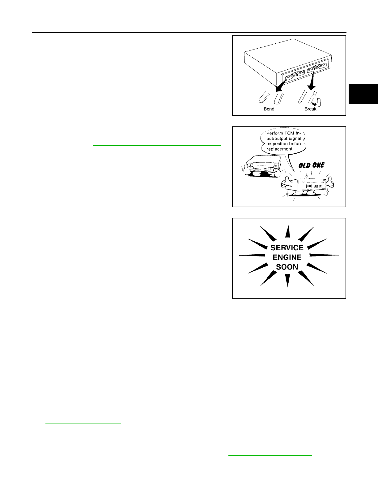
PRECAUTIONS
● When connec ting or disconnecting pin connector s into or
from TCM, take care not to dama ge pin terminals (bend or
break).
Make sure that there are not any ben ds or breaks on TCM
pin terminal, when connecting pin connectors.
● Before replacing TCM, perform TCM input/output signal
inspection and make sure wheth er TCM functions properly
or not. Refer to AT-37, "
INPUT/OUTPUT SIGNAL OF TCM" .
[RE4F04B]
A
B
AT
AAT470A
D
E
F
G
MEF040DA
● After performing each TROUBLE DIAGNOSIS, perform
“DTC (Diagnostic Trouble Code) CONFIRMATION PROCEDURE”.
The DTC should not be displ ayed in the “DTC CONFIRMATION PROCEDURE” if the repair is completed.
● Before procee ding with disassembly, thoroughly clea n the out-
side of the tran saxle. It is i mportant to preven t the in ternal parts
from becoming c ontaminated by dirt or other foreign matter.
● Disassembly should be done in a clean work area.
● Use lint-free cloth or towels for wiping parts clean. Common
shop rags can leav e f iber s th at co uld in te rf er e wi th th e oper a t ion
SAT964I
of the transaxle.
● Place disassembled parts in order for easier and proper asse mbly.
● All parts should be carefull y clean ed with a g eneral p urpose, non-flam mable so lvent be fore ins pection or
reassembly.
● Gaskets, seals and O-rings should be replaced any time the transaxle is disassembled.
● It is very important to perform functional tests whenever they are indicated.
● The valve body contains precision parts and requires extreme care when parts are removed and serviced.
Place disassembled valve body parts in order for easier and proper assembly. Care will also prevent
springs and small parts from becoming scattered or lost.
● Properly installed valves, sleeves, plugs, etc. will slide along bores in valve body under their own weight.
● Before assembly, apply a coat of recommended ATF to all parts. Apply petroleum jelly to protect O-rings
and seals, or hold bearings and washers in place during assembly. Do not use grease.
● Extreme care should be taken to avoid damage to O-rings, seals and gaskets when assembling.
● Replace ATF cooler if excessive foreign material is found in oil pan or clogging strainer. Refer to AT-12,
"ATF COOLER SERVICE" .
● After overhaul, refill the transaxle with new ATF.
● When the A/T drain plug is removed, only some of the fluid is drained. Old A/T fluid will remain in torque
converter and ATF cooling system.
Always follow the procedures when changing A/T fluid. Refer to AT-398, "
Changing A/T Fluid" .
H
I
J
K
L
M
Revision: July 2005 2006 Altima
AT-11
Page 34

PRECAUTIONS
[RE4F04B]
Service Notice or Precaution s
ECS0095N
FAIL-SAFE
The TCM has an electronic Fail-Safe (limp home mode). This allows the vehicle to be driven even if a major
electrical input/output device circuit is damaged.
Under Fail-Safe, t he vehicle alw ays runs in third gear, even with a shift lever p osition of 1, 2 o r D. The customer may complain of sluggish or poor acceleration.
When the ignition key is turned ON following Fail-Safe operation, A/T check (position) indicator lamp blinks for
about 8 seconds. [For “TCM Self-diagnostic Procedure (No Tools)”, refer to AT-60, "
TCM SELF-DIAGNOSTIC
PROCEDURE (NO TOOLS)" .]
The blinking of the A/T check (position) indicator lamp for about 8 seconds will appear only once and be
cleared. The customer may resume normal driving conditions.
Always follow the “Work Flow” (Refer to AT-68, "
Work Flow" ).
The SELF-DIAGNOSIS results will be as follows:
● The first SELF-DIAGNOSIS will indicate damage to the vehicle speed sensor or the revolution sensor.
● During the next SELF-DIAGNOSIS, performed after checking the sensor, no damages will be indicated.
TORQUE CONVERTER SERVICE
The torque converter should be replaced under any of the following conditions:
● External leaks in the hub weld area.
● Converter hub is scored or damaged.
● Converter pilot is broken, damaged or fits poorly into crankshaft.
● Steel particles are found after flushing the cooler and cooler li nes.
● Pump is damaged or steel particles are found in the converter.
● Vehicle has TCC shudder and/or no TCC apply. Replace only after all hydraulic and electrical diagnoses
have been made. (Converter clutch material may be glazed.)
● Converter is contaminate d with engine coolant containing antifreeze.
● Internal failure of stator roller clutch.
● Heavy clutch debris due to overheating (blue converter).
● Steel particles or clutch lining material found in fluid filter or on magnet when no internal parts in unit are
worn or damaged — indicates that lining material came from converter.
The torque converter should not be replaced if:
● The fluid has an odor, is discolored, and there is no evidence of metal or clutch facing particles.
● The threads in one or more of the converter bolt holes are damaged.
● Transa xl e fail ure di d no t displ ay evi d ence o f d ama ge d or wor n int er nal parts, steel p a rti cl es or cl ut ch plat e
lining material in unit and inside the fluid filter.
● Vehicle has been exposed to high mileage (only). The exception may be where the torque converter
clutch dampen er plat e li ning has se en ex ces s wear by vehi cl es op erate d in he avy a nd/ or con stant traffic,
such as taxi, delivery or police use.
ATF COOLER SERVICE
If A/T fluid contains frictional material (clutches, bands, etc.), replace radiator and flush cooler line using cleaning solvent and compres sed ai r after repair of A/T. Refer to CO-13, "
RADIATOR" .
OBD-II SELF-DIAGNOSIS
● A/T self-diagnosis is performed by the TCM in combination with the ECM. The results can be read through
the blinking pattern of th e A/T check (p osition) indic ator or the malfu nction indi cator lamp (MIL ). Refer to
the table on AT-49
● The self-diagnos ti c re su lts ind ic at ed by th e M IL ar e a uto m ati ca ll y s t ore d in bo th th e EC M an d TCM mem-
ories.
Always perform the procedure “HOW TO ERASE DTC” on AT-46
unnecessary blinking of the MIL.
● The following se lf-diagnostic i tems can be detec ted using ECM se lf-diagnostic re sults mode* only wh en
the A/T check (position) indicator lamp does not indicate any malfunctions.
– park/neutral position (PNP) switch
– A/T 1st, 2nd, 3rd, or 4th gear function
– A/T TCC S/V function (lock-up).
Revision: July 2005 2006 Altima
for the indicator used to display each self-diagnostic result.
to complete the re pair and av oid
AT-12
Page 35

PRECAUTIONS
[RE4F04B]
*: For details of OBD-II, refer to EC-53, "ON BOARD DIAGNOSTIC (OBD) SYSTEM" .
● Certain systems and components, especially those related to OBD, may use a new style slide-
locking type harness con nec tor.
For description and how t o disconnect, refer to GI-24, "
How to Check Terminal" .
A
B
AT
D
E
F
G
H
K
M
I
J
L
Revision: July 2005 2006 Altima
AT-13
Page 36
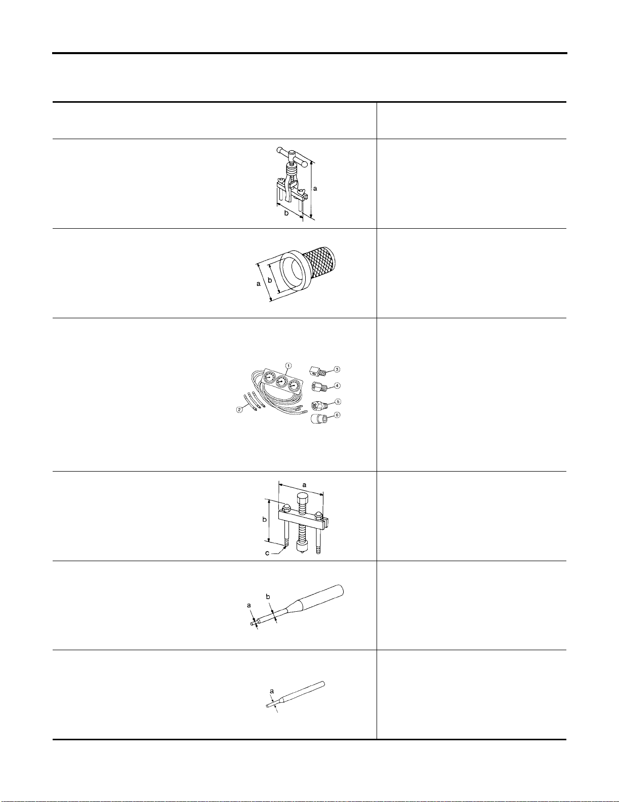
PREPARATION
[RE4F04B]
PREPARATION PFP:00002
Special Service Tools
The actual shapes of Kent-Moore tools may differ from those of spe ci al se rvice tools illustrated here.
Tool number
(Kent-Moore No.)
Tool name
KV381054S0
(J-34286)
Puller
ST33400001
(J-26082)
Drift
(J-34301-C)
Oil pressure gauge set
1 (J-34301-1)
Oil pressure gauge
2 (J-34301-2)
Hoses
3 (J-34298)
Adapter
4 (J-34282-2)
Adapter
5 (790-301-1230-A)
60° Adapter
6 (J-34301-15)
Square socket
ST27180001
(J-25726-A)
Puller
NT414
NT086
AAT896
Description
● Removing differential side oil seals
● Removing differential side bearing outer
race
● Removing idler gear bearing outer race
a: 250 mm (9.84 in)
b: 160 mm (6.30 in)
● Installing differential side oil seal
(RH side)
● Installing oil seal on oil pump housing
a: 60 mm (2.36 in) dia.
b: 47 mm (1.85 in) dia.
Measuring line pressure
Removing idler gear
a: 100 mm (3.94 in)
b: 110 mm (4.33 in)
c: M8 x 1.25P
ECS0095P
NT424
ST23540000
(J-25689-A)
Pin punch
Removing and installing parking rod plate and
manual plate pins
a: 2.3 mm (0.091 in) dia.
b: 4 mm (0.16 in) dia.
NT442
ST25710000
(J-25689-A)
Pin punch
NT410
Revision: July 2005 2006 Altima
AT-14
Aligning groove of manual shaft and hole of
transaxle case
a: 2 mm (0.08 in) dia.
Page 37
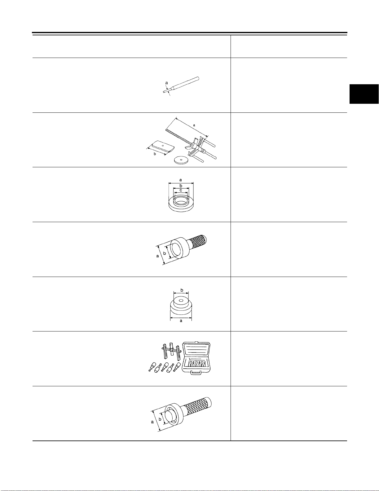
PREPARATION
[RE4F04B]
Tool number
(Kent-Moore No.)
Tool name
KV32101000
(J-25689-A)
Pin punch
KV31102400
(J-34285 and J-34285-87)
Clutch spring compressor
KV40100630
(J-26092)
Drift
ST30720000
(J-25405 and J-34331)
Bearing installer
NT410
NT423
NT107
Description
● Removing and installing manual shaft re-
taining pin
● Removing and installing pinion m at e shaf t
lock pin
a: 4 mm (0.16 in) dia.
● Removing and installing clutch r etu rn
springs
● Installing low and reverse brake piston
a: 320 mm (12.60 in)
b: 174 mm (6.85 in)
● Installing reduction gear bearing inner race
● Installing idler gear bearing inner race
a: 67.5 mm (2.657 in) dia.
b: 44 mm (1.73 in) dia.
c: 38.5 mm (1.516 in) dia.
Installing idler gear bearing outer race
a: 77 mm (3.03 in) dia.
b: 55.5 mm (2.185 in) dia.
A
B
AT
D
E
F
G
H
I
ST35321000
( — )
Drift
(J-34291-A)
Shim setting gauge set
ST33230000
(J-25805-01)
Drift
NT115
NT073
NT101
NT084
Installing output shaft bearing
a: 49 mm (1.93 in) dia.
b: 41 mm (1.61 in) dia.
● Selecting oil pump cover bearing race and
oil pump thrust washer
● Selecting side gear thrust washer
Installing differential side bearing inner race
(RH side)
a: 51 mm (2.01 in) dia.
b: 28.5 mm (1.122 in) dia.
J
K
L
M
Revision: July 2005 2006 Altima
AT-15
Page 38
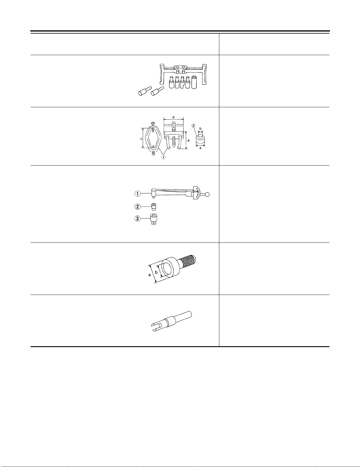
PREPARATION
[RE4F04B]
Tool number
(Kent-Moore No.)
Tool name
(J-34290)
Shim selecting tool set
ST3306S001
(J-22888-D)
Differential side bearing puller set
1 ST33051001
(J-22888-D)
Puller
2 ST33061000
(J-8107-2)
Adapter
ST3127S000
(J-25765-A)
Preload gauge
1 GG91030000
(J-25765-A)
Torque wrench
2 HT62940000
( — )
Socket adapter
3 HT62900000
( — )
Socket adapter
ST35271000
(J-26091)
Drift
Description
Selecting differential side bearing adjusting
shim
NT080
Removing differential side bearing in ner race
a: 38 mm (1.50 in) dia.
b: 28.5 mm (1.122 in) dia.
c: 130 mm (5.12 in)
d: 135 mm (5.31 in)
e: 100 mm (3.94 in)
AMT153
Checking differential side bearing preload
NT124
Installing idler gear
a: 72 mm (2.83 in) dia.
b: 63 mm (2.48 in) dia.
NT115
(J-39713)
Preload adapter
NT087
Revision: July 2005 2006 Altima
AT-16
● Selecting differential side bearing adjusting
shim
● Checking differential side bearing preload
Page 39
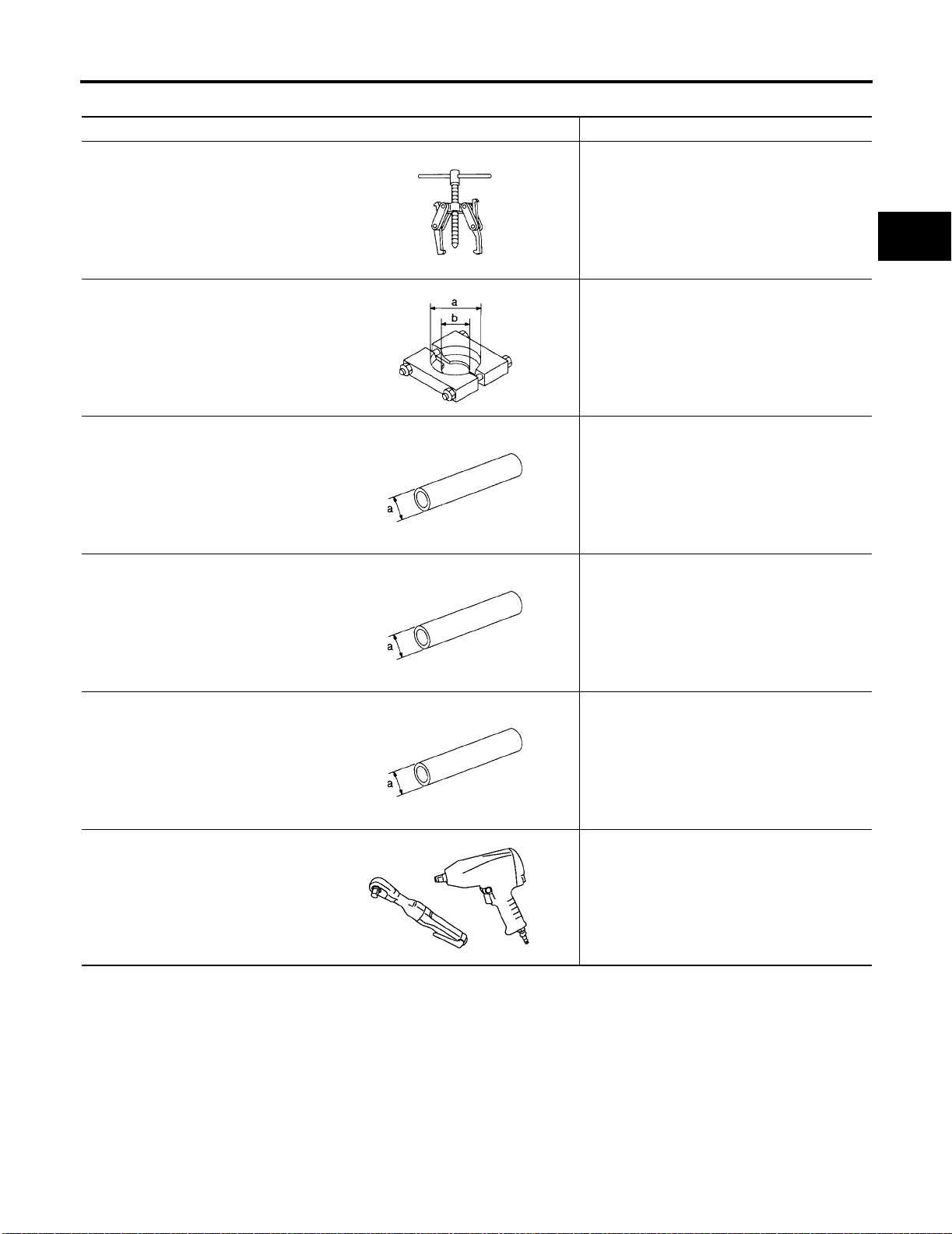
PREPARATION
[RE4F04B]
Commercial Service Tools
Tool name Description
Puller
NT077
Puller Removing reduction gear bearing inn er race
NT411
Drift Installing needle bearing on bearing retain er
NT083
Drift Removing needle bearing from bearing retain-
● Removing idler gear bearin g inner ra ce
● Removing and installing band ser vo pi st on
snap ring
a: 60 mm (2.36 in) dia.
b: 35 mm (1.38 in) dia.
a: 36 mm (1.42 in) dia.
er
a: 33.5 mm (1.319 in) dia.
ECS0095Q
A
B
AT
D
E
F
G
H
I
NT083
Drift Installing differential side bearing outer race
(RH side)
a: 75 mm (2.95 in) dia.
NT083
Power tool
PBIC0190E
● Removing transaxle asse mbly
● Removing transaxle oil pan
● Removing transaxle case and cover
J
K
L
M
Revision: July 2005 2006 Altima
AT-17
Page 40

A/T FLUID
[RE4F04B]
A/T FLUID PFP:KLE40
Changing A/T Fluid
ECS00EMQ
1. Run the engine to warm up the transaxle until the fluid is at full o perating temperature “HOT”.
Temperature range
COLD : 30° – 50° C (86° – 122° F)
HOT : 50° – 80° C (122° – 176° F)
2. Stop the engine.
3. Remove the engine undercover.
4. Drain the A/T fluid by removing the drain plug. Reinstall the drain
plug to the specified torque using a new drain washer.
Drain plug : Refer to AT-275, "
REMOVAL AND
INSTALLATION" .
WLIA0009E
5. Refill the transaxle with new specified A/T fluid through the A/T fluid charging pipe. Always refill the tran-
saxle with the same volume amount that was drained out.
CAUTION:
Do not overfill the transaxle.
Fluid grade and capacity : Refer to MA-12, "Fluids and Lubricants" .
6. Run the engine at id le speed for five minutes.
7. Check fluid level and condition. Refer to AT-3 9 8 , "
Checking A/T Fluid" . If the fluid is still contaminated,
repeat step 2 through 5.
Checking A/T Fluid
ECS00EMR
1. Warm up the engine.
2. Check for any transaxle fluid leaks.
3. Before drivin g, the fluid level can be chec ked at fluid tempera-
ture using the “COLD” range on the A/T fluid level gauge.
Temperature range
COLD : 30° – 50° C (86° – 122° F)
HOT : 50° – 80° C (122° – 176° F)
WLIA0013E
a. Park the vehicle on a level surface and set parking brake.
b. Start the engine and mo ve the transaxle select or lever through each gea r position. Leave the s elector
lever in the “P” park position.
Revision: July 2005 2006 Altima
AT-18
Page 41
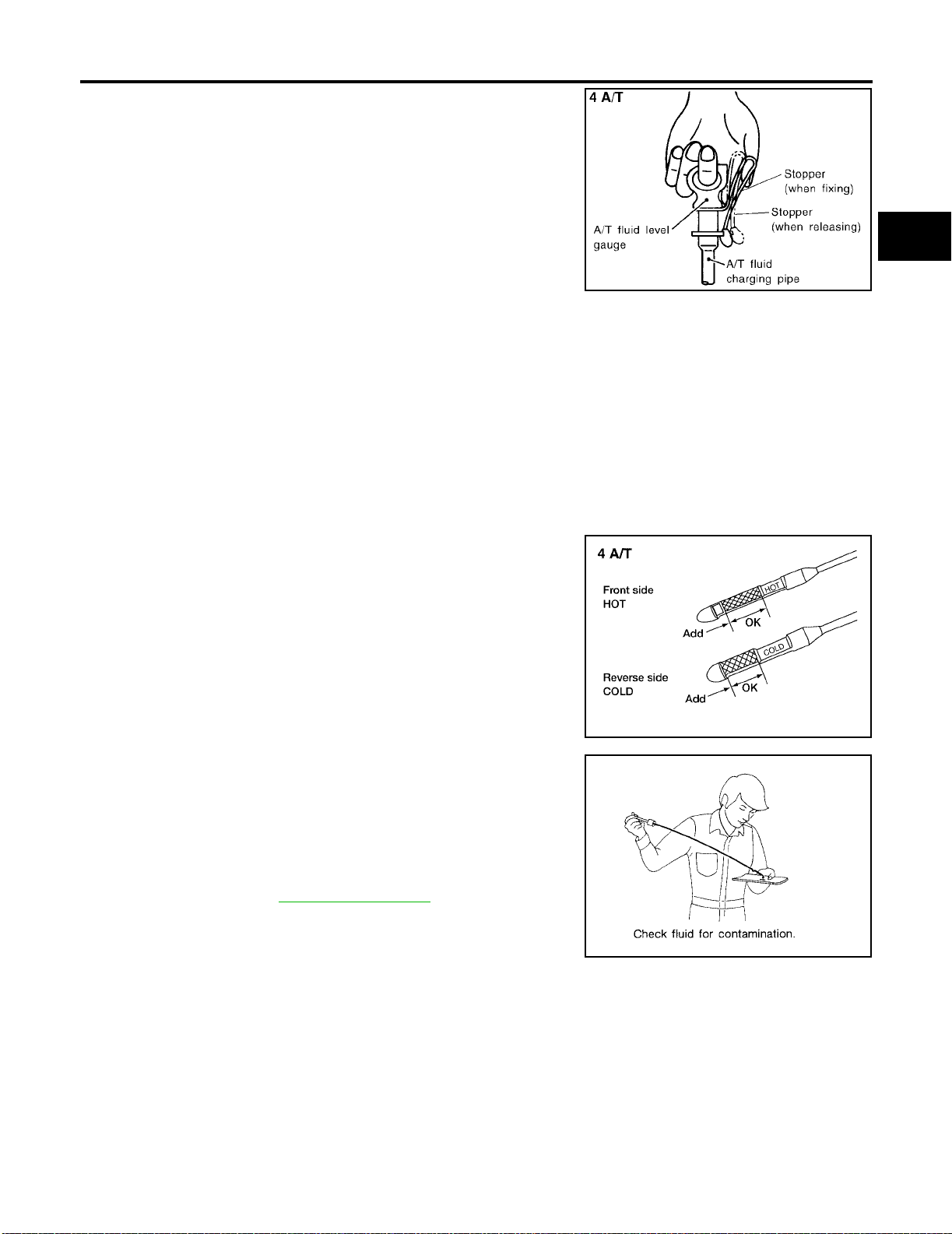
A/T FLUID
[RE4F04B]
c. Check the fluid level with the en gine idling.
CAUTION:
Firmly secure the A/T fluid level gauge into the A/T fluid
charging pipe using the attached stopper, this will provide
an accurate reading on the gauge.
WLIA0008E
d. Remove the A/T fluid level gauge and wipe it clean with a lint-free paper.
e. Re-insert the A/T fluid level gauge into the charging pipe as far as it will go.
f. Remove the A/T fluid level gauge an d note the reading. If the reading is a t or below the low side of the
range, add the necessary specified A/T fluid through the A/T fluid charging pipe and then re-insert the A/T
fluid level gauge.
CAUTION:
● Do not overfill the transaxle.
● Firmly secure the A/T fluid le vel ga uge into the A/T fluid ch arg ing pipe using the attached s top-
per , th is will prov ide an accu rate readi ng on the gau ge, an d wil l keep th e gau ge in po sit ion wh ile
driving.
4. Drive the vehicle for approximately 5 minutes at moderate speeds.
5. Re-check the fluid level at fluid temperatures using the “HOT”
range on the A/T fluid level gauge.
CAUTION:
Firmly secure the A/T fluid level gauge into the A/T fluid
charging pipe using the attached stopper, this will provide
an accurate reading on the gauge, a nd will keep the gauge
in position while driving.
Temperature range
COLD : 30° – 50° C (86° – 122° F)
HOT : 50° – 80° C (122° – 176° F)
WLIA0013E
A
B
AT
D
E
F
G
H
I
J
K
6. Check the fluid fo r the following c onditions:
● If the fluid is very dark or smells burned, refer to the AT section
for checking the operation of the transaxle. Flush the AT fluid
cooling system after repairing the transaxle.
● If the fluid contains frictional material (from the clutches or
bands), remove the radiator and flush the cooler lines using a
cleaning solvent an d compres sed air afte r completi ng repairs to
the transaxle. Refer to CO-13, "
A/T Fluid Cooler Cleaning
RADIATOR" .
SMA853B
ECS00EMS
Whenever an au tomatic transaxle is repaired, overhauled, or replaced, the A/T fluid cooler mounted in the
radiator must be inspected and cleaned.
Metal debris and fri ct ion ma teri al, i f pres ent, can beco me trapp ed i n the A/T fl uid c oole r. This debris ca n co ntaminate the newly serviced A/T or, in severe cases, can block or restrict the flow of A/T fluid. In either case,
malfunction of the newly serviced A/T may result.
Debris, if present, may build up as A/T fluid enters the cooler inlet. It will be necessary to back flush the cooler
through the cooler outlet in order to flush out any built up debris.
A/T FLUID COOLER CLEANING PROCEDURE
1. Position an oil pan under the automatic transaxl e's inlet and out let cooler hoses.
Revision: July 2005 2006 Altima
AT-19
L
M
Page 42
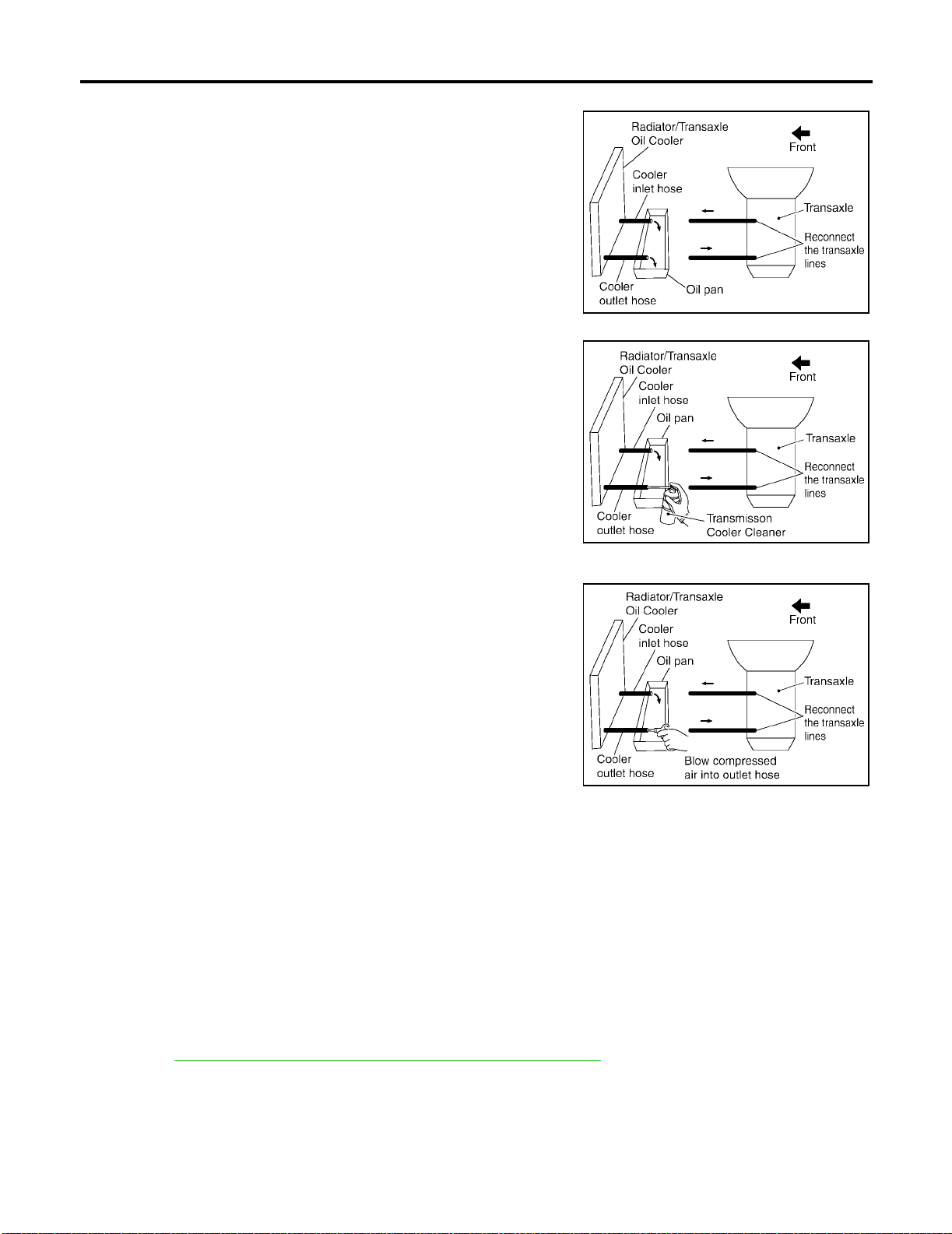
A/T FLUID
2. Identify the inlet and outlet fluid cooler hoses.
3. Disconnect t he fl uid co oler inl et and outl et ru bber hos es fro m the
steel cooler tubes or bypass valve.
NOTE:
Replace the cooler hoses if rubber material from the hose
remains on the tube fitting.
4. Allow any A/T fluid that rem a in s i n the cooler hoses to drain int o
the oil pan.
5. Insert the extension adapter hose of a can of Transmission
Cooler Cleaner (Nissa n P/N 999M P-AM0 06) into the co oler ou tlet hose.
CAUTION:
● Wear safety glasses and rubber gloves when spraying
the Transmission Cooler Cleaner.
● Spray cooler cleaner only with adequate ventilation.
● Avoid contact with eyes and skin.
● Do not breath vapors or spray mist.
6. Hold the hose and can as high as possible and spray Transmission Cooler Cleaner in a continuous stream into the cooler outlet
hose until fluid flows out of the cooler inlet hose for 5 seconds.
7. Insert the tip of an air gun into the end of the cooler outlet hose.
8. Wrap a shop rag around the air gun tip and of the cooler outlet
hose.
[RE4F04B]
SCIA5628E
SCIA5629E
SCIA5630E
9. Blow compressed air regulated to 5 - 9 kg/cm
2
(70 - 130 psi) throug h the cool er out let ho se fo r 10 se c-
onds to force out any remaining fluid.
10. Repeat steps 5 through 9 three additional times.
11. Position an oil pan under the banjo bolts that connect the fluid cooler steel lines to the transaxle.
12. Remove the banjo bolts.
13. Flush each steel line from the cooler side back toward the transaxle by spraying Transmission Cooler
Cleaner in a continuous stream for 5 seconds.
14. Blow compre sse d ai r re gu la te d t o 5 - 9 k g/ cm
2
(70 - 130 psi) through each steel line from the cooler side
back toward the transaxle f or 10 seconds to force out any remai ning fluid.
15. Ensure all debris is removed from the steel cooler lines.
16. Ensure all debris is removed from the banjo bolts and fittings.
17. Perform AT-400, "
A/T FLUID COOLER DIAGNOSIS PROCEDURE" .
A/T FLUID COOLER DIAGNOSIS PROCEDURE
NOTE:
Insufficient cleaning of the cooler inlet hose exterior may lead to inaccurate debris identification.
1. Position an oil pan under the automatic transaxle's inlet and outlet coole r hoses.
2. Clean the exterior and tip of the cooler inlet ho se.
Revision: July 2005 2006 Altima
AT-20
Page 43
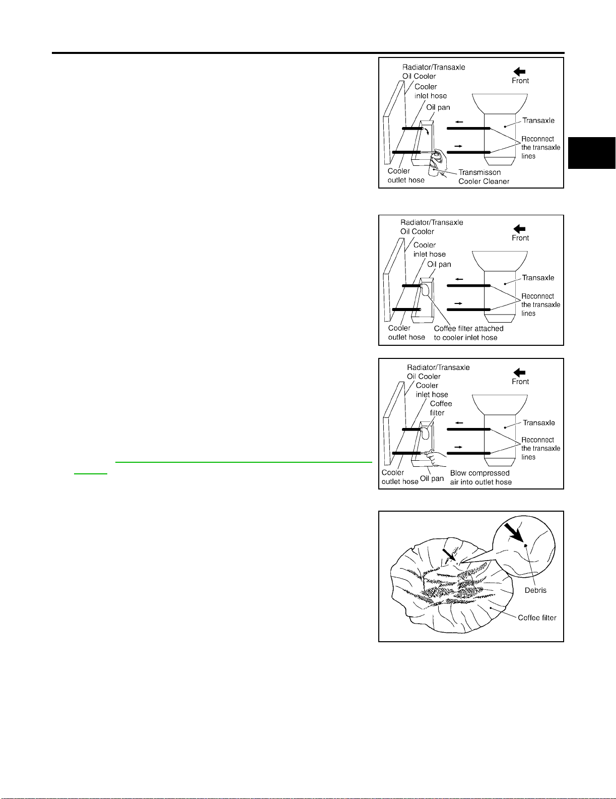
A/T FLUID
3. Insert the extension adapter hose of a can of Transmission
Cooler Cleaner (Nissan P/N 99 9MP-AM00 6) into the coole r outlet hose.
CAUTION:
● Wear safety glasses and rubber gloves when spraying
the Transmission Cooler Cleaner.
● Spray cooler cleaner only with adequate ventilation.
● Avoid contact with eyes and skin.
● Do not breat h vapors or spr ay mist.
4. Hold the hose and can as high as possible and spray Transmission Cooler Cleaner in a continuous stream into the cooler outlet
hose until fluid flows out of the cooler inlet hose for 5 seconds.
5. Tie a common white, basket-type coffee filter to the end of the
cooler inlet hose.
[RE4F04B]
A
B
AT
SCIA5629E
D
E
F
G
6. Insert the tip of an air gun into the end of the cooler outlet hose.
7. Wrap a shop rag around the air gun tip and end of cooler outlet
hose.
2
8. Blow co mpressed air regu lated to 5 - 9 kg /cm
(70 - 130 psi)
through the cool er outlet hose to force any remaining A/T fluid
into the coffee filter.
9. Remove the coffee filter from the end of the cooler inlet hose.
10. Perform AT -4 01 , "
A/T FLUID COOLER INSPECTION PROCE-
DURE" .
A/T FLUID COOLER INSPECTION PROCEDURE
1. Inspect the coffee filter for debris.
a. If smal l metal debris less than 1mm (0.040 in) in size or metal
powder is found in the coffee filter, this is normal. If normal
debris is found, the A/T fluid cooler/radiator can be re-used and
the procedur e is ended.
SCIA5631E
H
I
J
K
SCIA5632E
L
M
SCIA2967E
Revision: July 2005 2006 Altima
AT-21
Page 44
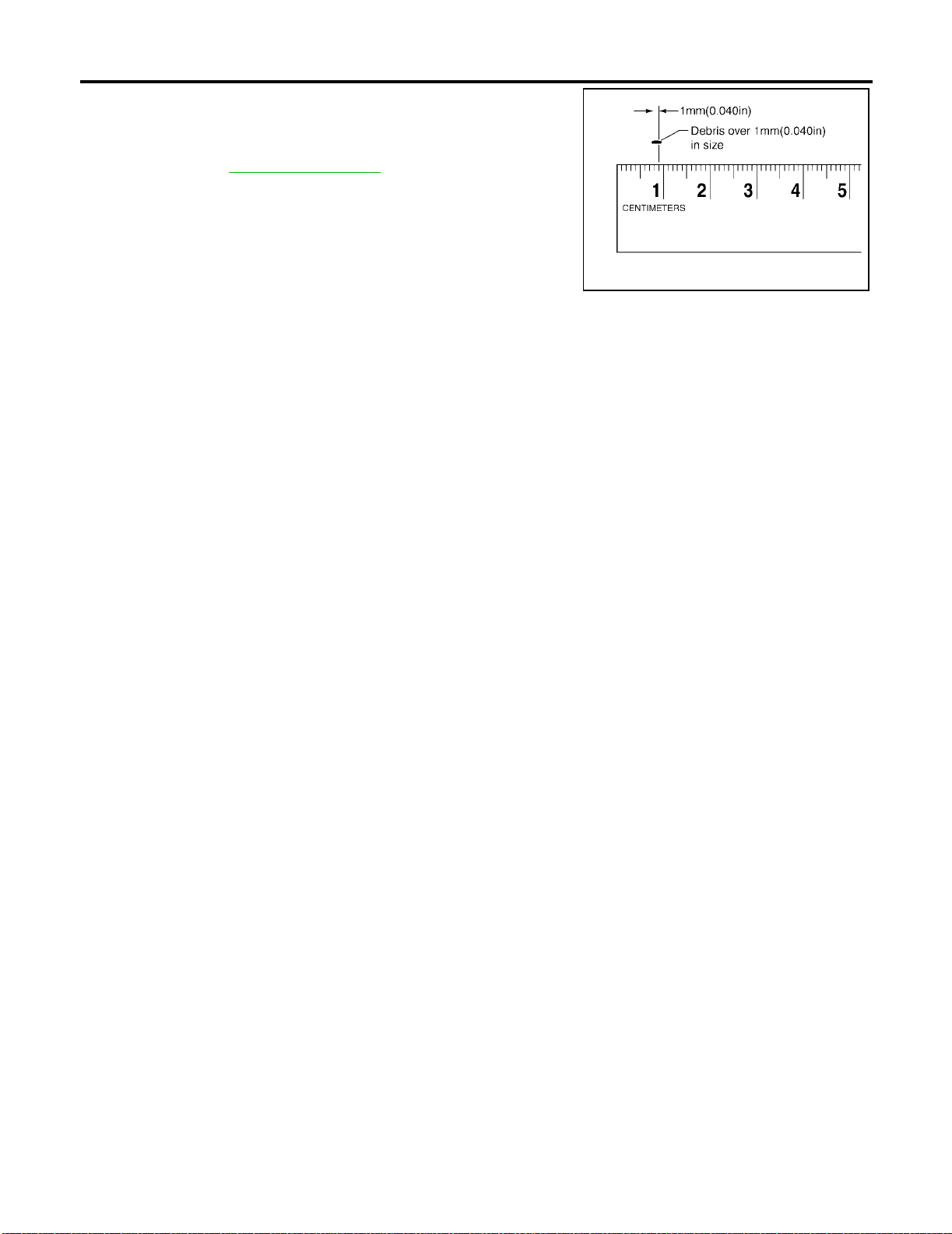
A/T FLUID
b. If one or more pieces of debris are found that are over 1mm
(0.040 in) in size and/or peeled clutch facing material is found in
the coffee filter, the fluid coo ler is no t service able. The A/T fluid
cooler/radiator must be replaced and the inspection procedure is
ended. Refer to CO-13, "
A/T FLUID COOLER FINAL INSPECTION
After performing all proced ures, ensure th at all remaining oil is cleaned f rom all components.
RADIATOR" .
[RE4F04B]
SCIA5659E
Revision: July 2005 2006 Altima
AT-22
Page 45
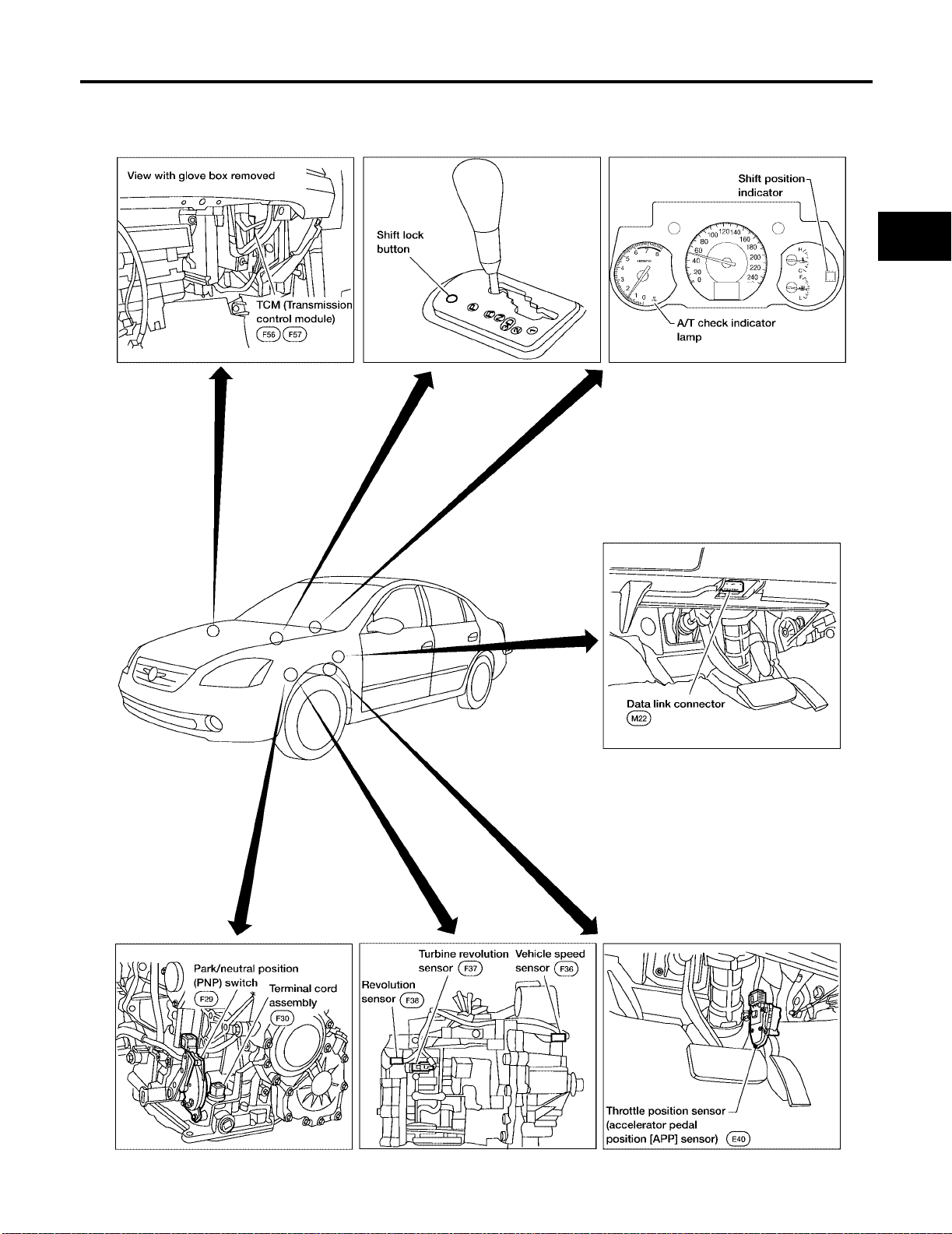
OVERALL SYSTEM
[RE4F04B]
OVERALL SYSTEM PFP:00000
A/T Electrical Parts Location
ECS0095R
A
B
AT
D
E
F
G
H
K
M
I
J
L
WCIA0474E
Revision: July 2005 2006 Altima
AT-23
Page 46
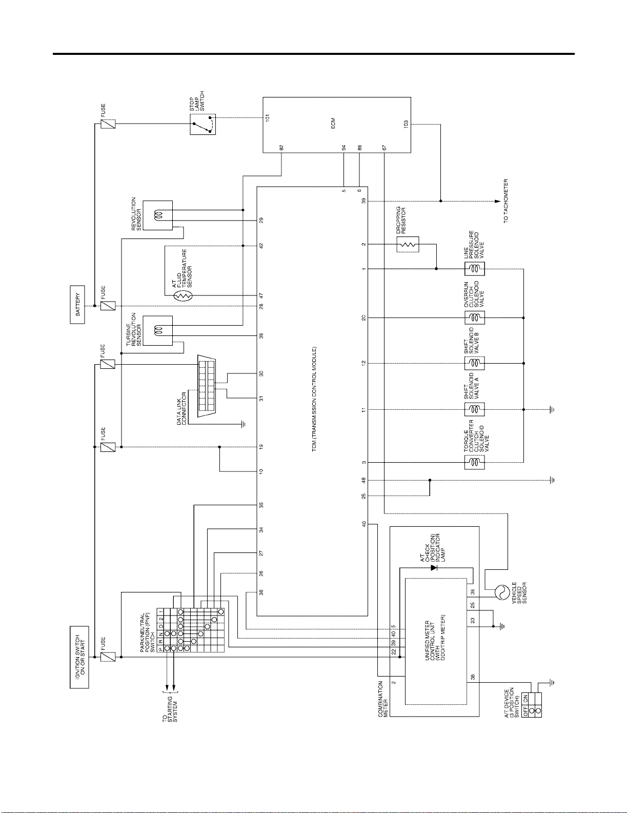
OVERALL SYSTEM
[RE4F04B]
Circuit Diagram
ECS0095S
BCWA0481E
Revision: July 2005 2006 Altima
AT-24
Page 47
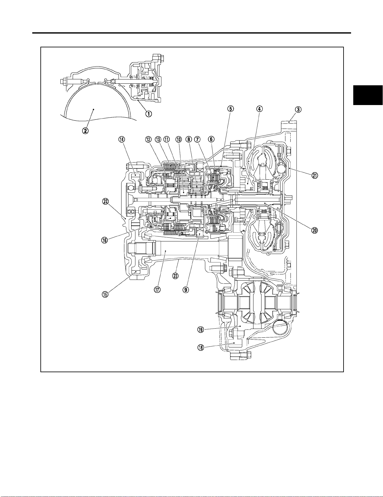
OVERALL SYSTEM
[RE4F04B]
Cross-sectional View
ECS0095T
A
B
AT
D
E
F
G
H
1. Band servo piston 2. Reverse clutch drum 3. Conver te r hous in g
4. O il pum p 5. Brake band 6. Reverse cl utch
7. High clutch 8. Front planetary gear 9. Low one-way clutch
10. Rear planetary gear 11. Forward clutch 12. Overrun clutch
13. Low & reverse brake 14. Output gear 15. Idler gear
16. Forward one-way clutch 17. Pinion red uct io n gear 18. Final gear
19. Differential case 20. Input shaft 21. Torque converter
22. Side cover 23. Transaxle case
I
J
K
L
M
SCIA3174E
Revision: July 2005 2006 Altima
AT-25
Page 48
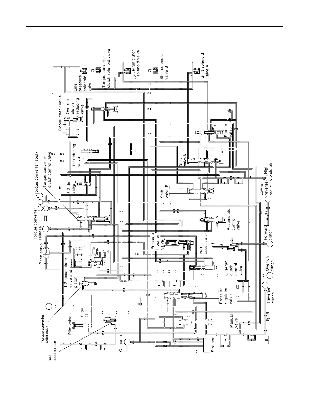
OVERALL SYSTEM
[RE4F04B]
Hydraulic Control Circuit
ECS0095U
LCIA0040E
Revision: July 2005 2006 Altima
AT-26
Page 49
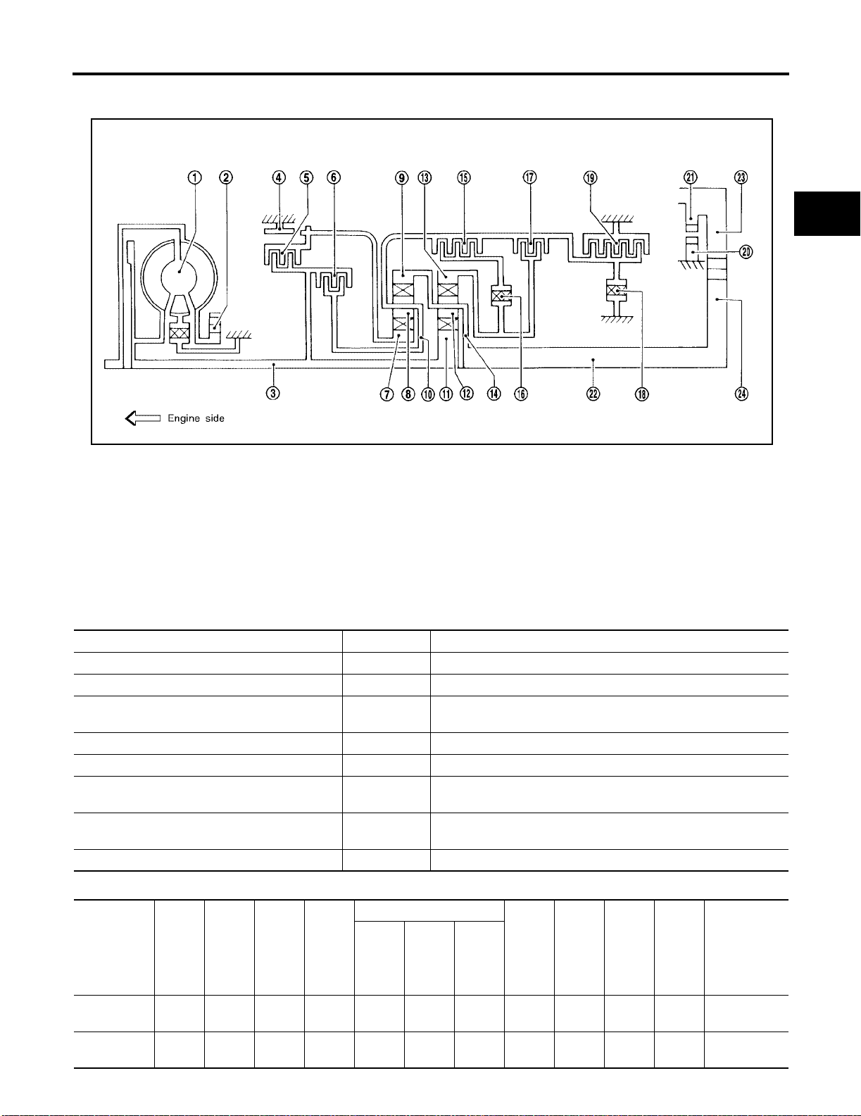
OVERALL SYSTEM
[RE4F04B]
Shift Mechanism
ECS0095V
CONSTRUCTION
SAT998I
1. Torque converter 2. Oil pump 3. Inpu t sha ft
4. Brake band 5. Reverse clutch 6. High clutch
7. Front sun gear 8. Front pinion gear 9. Front internal gear
10. Front planetary carrier 11. Rear sun gear 12. Rear pinion gear
13. Rear internal gear 14. Rear pla netary carrie r 15. Forward clutch
16. Forward one-way clutch 17. Overrun clutch 18. Low one-way clutch
19. Low & reverse brake 20. Parking pawl 21. Parking gear
22. Output shaft 23. Idle gear 24. Output gear
FUNCTION OF CLUTCH AND BRAKE
Clutch and brake components Abbr. Function
Reverse clutch 5 R/C To transm it input pow er to front sun gear 7 .
High clutch 6 H/C To transmit input power to fr ont planetary carr ier 10 .
Forward clutch 15 F/C To connect front planetary carrier 10 with forward one-way clutch
16 .
Overrun clutch 17 O/C To connect front planetary carrier 10 with rear internal gear 13 .
Brake band 4 B/B To lock front sun gear 7 .
Forward one-way clutch 16 F/O.C When forward clutch 15 is engaged, to stop rear internal gear 13
from rotating in opposite direction against engine rev olu tion.
Low one-way clutch 18 L/O.C To stop front planetary carrier 10 from rotating in opposite direc-
tion against engine revolution.
Low & reverse brake 19 L & R/B To lock front planetary carrier 10 .
A
B
AT
D
E
F
G
H
I
J
K
L
M
CLUTCH AND BAND CHART
Band servo For-
Re-
Shift position
P
RO O
verse
clutch
High
clutch
5
6
Revision: July 2005 2006 Altima
For-
ward
clutch
15
Over-
run
clutch
17
2nd
apply
3rd re-
lease
AT-27
4th
apply
ward
oneway
clutch
16
Low
oneway
clutch
18
Low &
reverse
brake
19
Lock-
up
Remarks
PARK POSI-
TION
REVERSE
POSITION
Page 50

OVERALL SYSTEM
[RE4F04B]
Band servo For-
Re-
Shift position
N
D*4
2
1
*1: Operates when selector lever is set in 3 position.
*2: Oil pressure is applied to bot h 2nd “apply” side and 3r d “release” side of band ser vo piston. Howev er, brake band does not contra ct
because oil pressure area on the “release” side is grea te r than tha t on the “apply” side.
*3: Oil pressure is applied to 4th “apply” side in condi tion *2 above, and brake band contracts.
*4: A/T will not shift to 4th when selector lever is set in 3 position.
*5: Operates when selector lever is set in 3 position.
O: Operates
A: Operates when throttle opening is less than 3/16, activa ting engine brake.
B: Operates during “progressive” accelerati on.
C: Operates but does not affect power transmissi on.
D: Operates when throttle opening is less tha n 3/1 6, bu t does not affect engine bra ke.
verse
clutch
1st O *1D B B
2nd O *1 A O B
3rd O O *1 A *2C C B *5O
4th O C *3C C O O
1st O D B B Automatic
2nd O A O B
1st O O B O Locks (held
2nd O O O B
High
clutch
5
6
For-
ward
clutch
15
Over-
run
clutch
17
2nd
apply
3rd re-
lease
4th
apply
ward
one-
way
clutch
16
Low
one-
way
clutch
18
Low &
reverse
brake
19
Lock-
up
Remarks
NEUTRAL
POSITION
Automatic
shift
1 ⇔ 2 ⇔ 3
⇔ 4
shift
1 ⇔ 2 ⇐ 3
stationary) in
1st speed
1 ⇐ 2 ⇐ 3
Revision: July 2005 2006 Altima
AT-28
Page 51
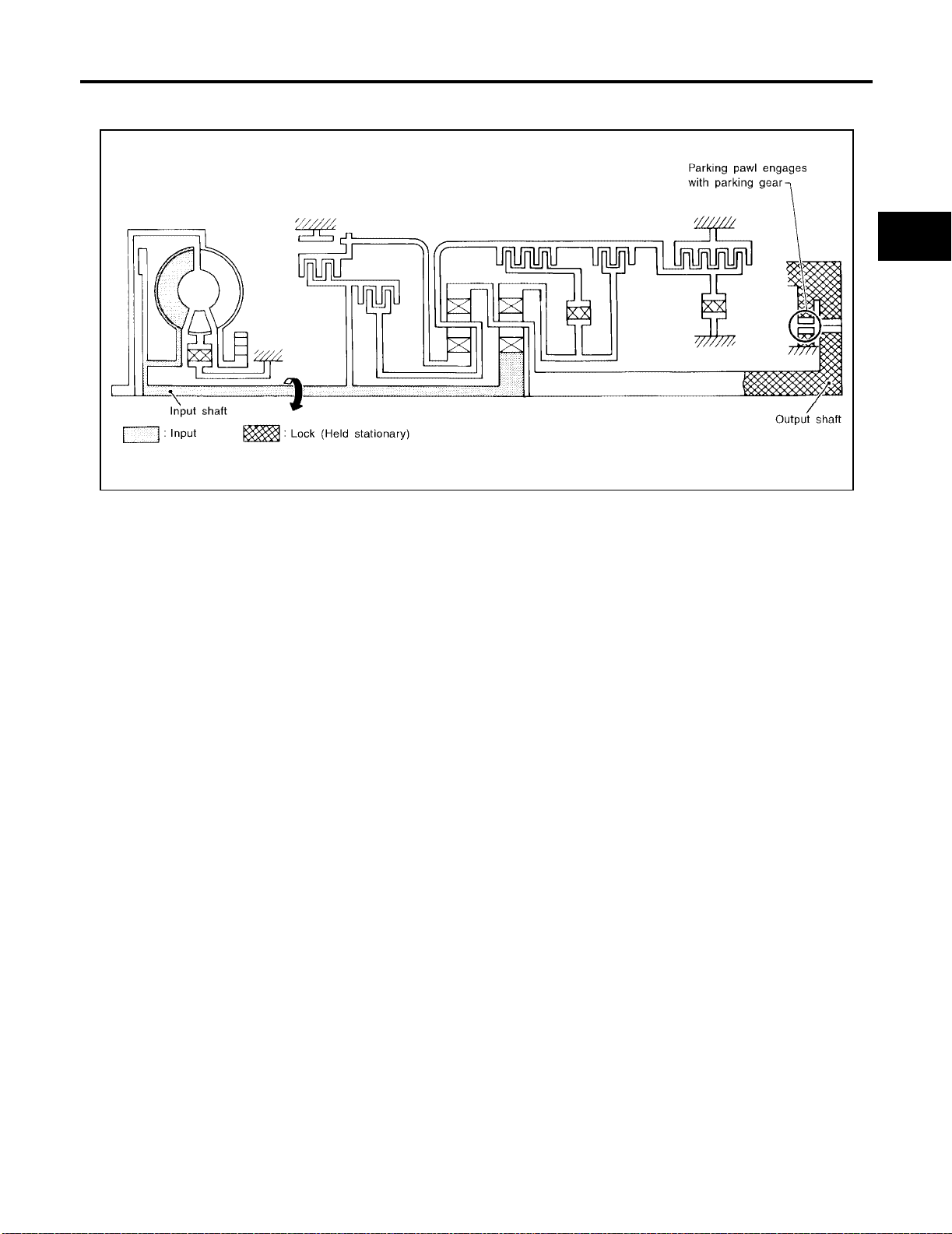
POWER TRANSMISSION
P and N Positions
OVERALL SYSTEM
[RE4F04B]
A
B
AT
D
E
F
● P position
Similar to the N posi tion, the c lutch es d o not opera te. Th e parkin g pawl eng ages with t he parking ge ar to
mechanically hold the output shaft so that the power train is locked.
● N position
Power from the input shaft is not transmitted to the output s haft because the clutches do not operate.
SAT991I
G
H
I
J
K
L
M
Revision: July 2005 2006 Altima
AT-29
Page 52
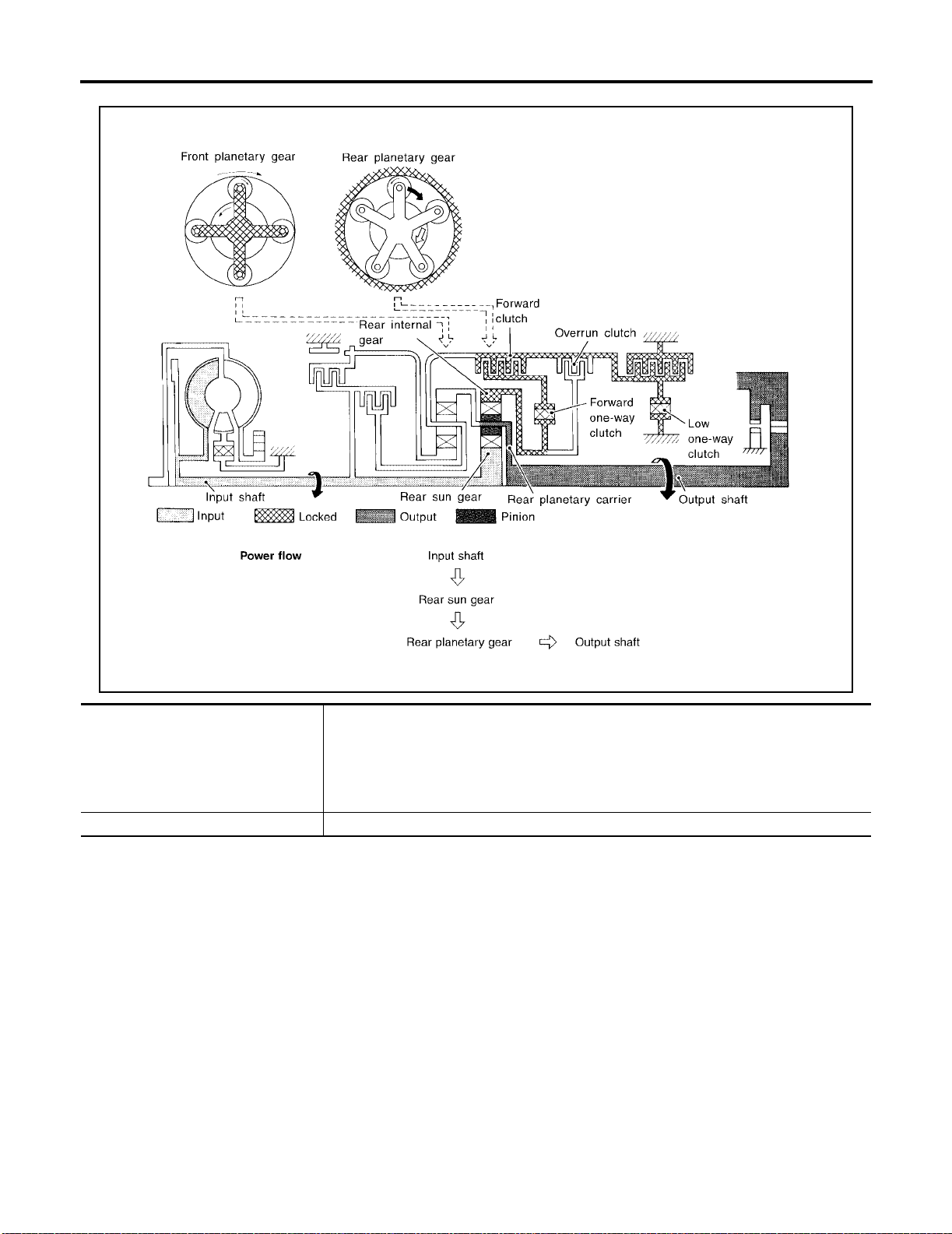
11 Position
OVERALL SYSTEM
[RE4F04B]
WCIA0355E
● Forward clutch
● Low one-way clutch
● Forward one-way clutch
● Overrun clutch
● Low and reverse brake
Engine brake Overrun clutch always engages, therefore engine brake can be obtained when decelerating.
As overrun clutch engages, rear internal gear is locke d by th e oper at ion of low and rev ers e
brake.
This is different from that of D
1 , 21 , and 31 .
Revision: July 2005 2006 Altima
AT-30
Page 53
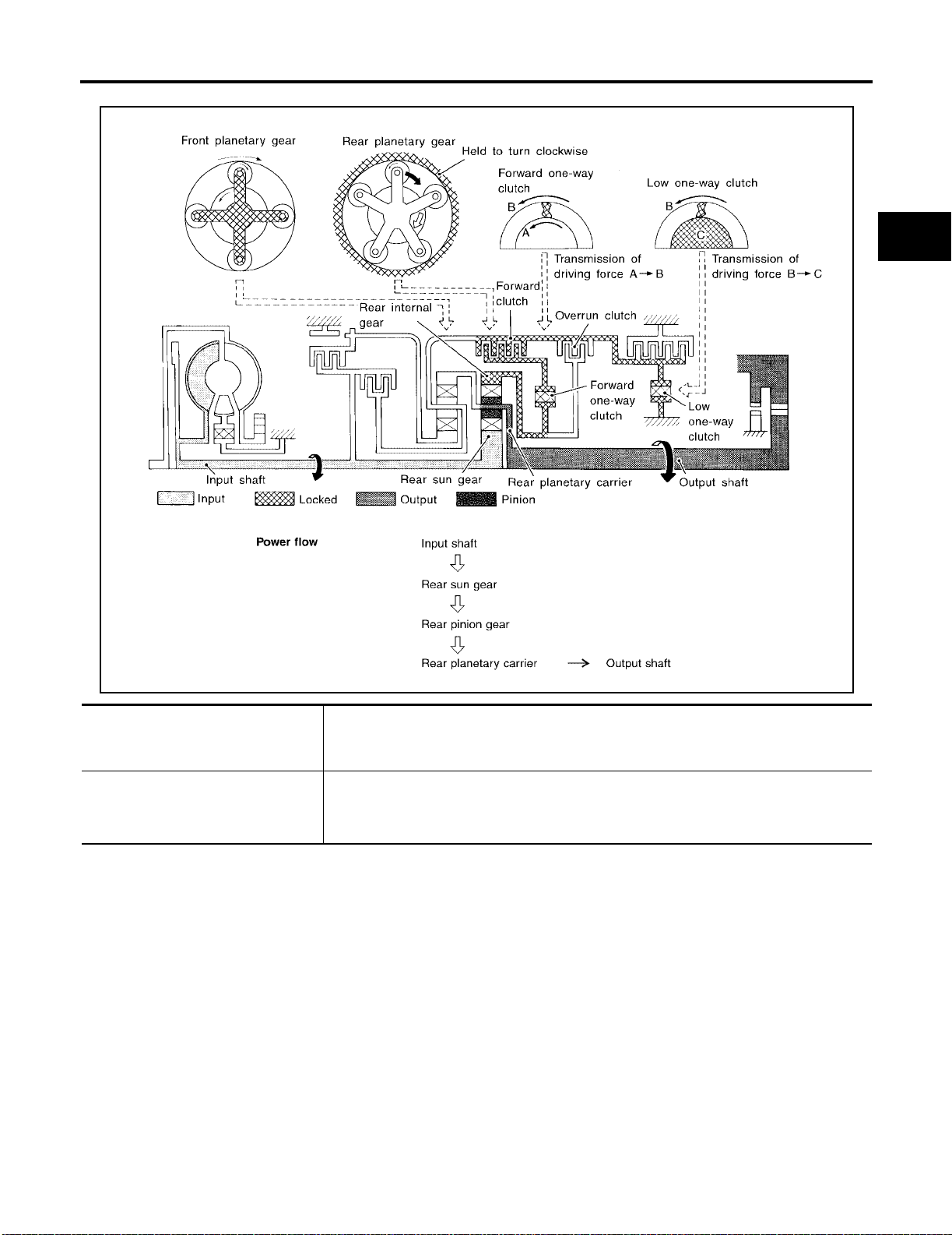
D1 and 21 Positions
OVERALL SYSTEM
[RE4F04B]
A
B
AT
D
E
F
G
● Forward one-way clutch
● Forward clutch
● Low one-way clutch
Overrun clutch
engagement conditions
(Engine brake)
WCIA0356E
Rear internal gear is locked to rotate counterclockwi se because of the functioning of these
three clutches.
D
1 : Overdrive control switch OFF and throttle openi ng is le ss th an 3/ 16
2
1 : Always engaged
1 and 21 positions, engine brake i s not activ ate d due to free turni ng of low one -way
At D
clutch.
H
I
J
K
L
M
Revision: July 2005 2006 Altima
AT-31
Page 54
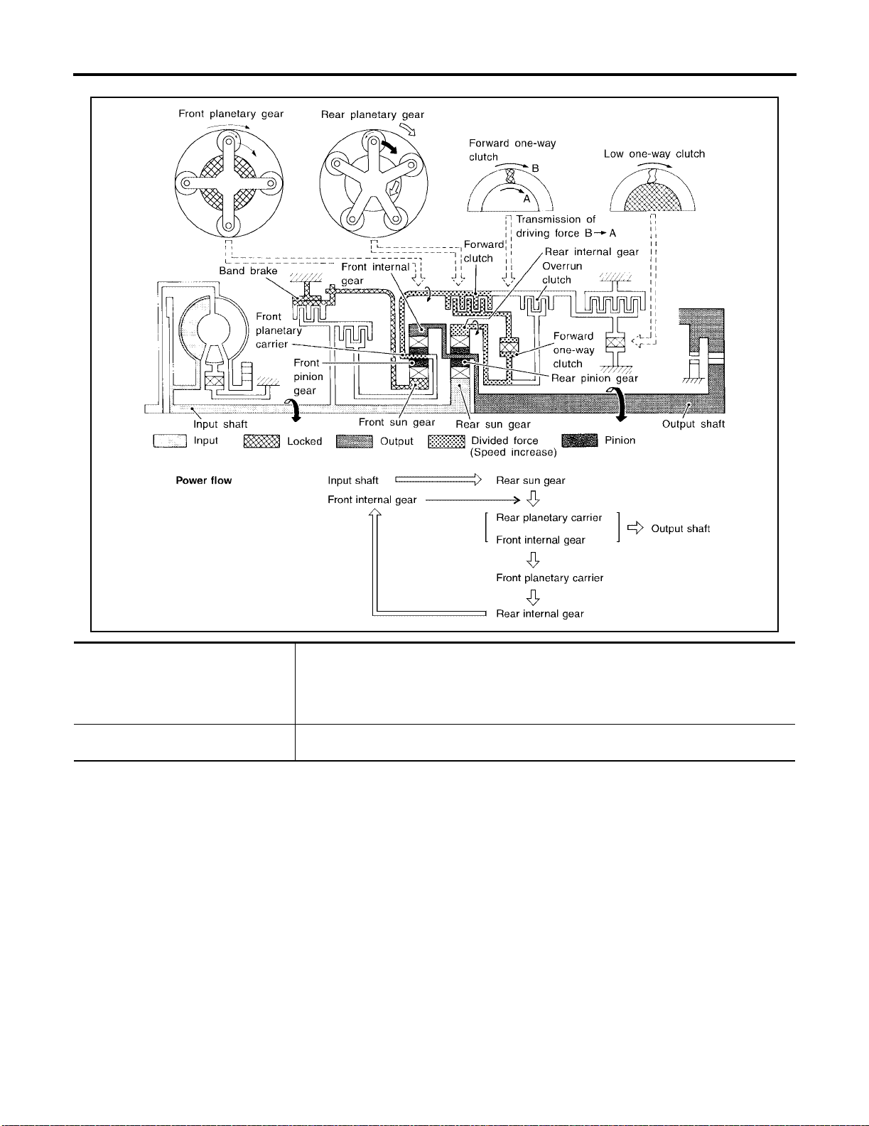
D2 , 32 , 22 and 12 Positions
OVERALL SYSTEM
[RE4F04B]
● Forward clutch
● Forward one-way clutch
● Brake band
Overrun clutch
engagement conditions
WCIA0357E
Rear sun gear drives rear planetary carrier and combined front internal gear. Front internal
gear now rotates around front sun gear accompanying fron t planetary car rie r.
As front planetary carrier transfers the power to rear internal gear through forward clutch and
forward one-way clutch, this rotation of rear internal gear increases the speed of rear planetary carrier compared with that of the 1st speed.
2 : Gear selector lever is set in 3 position and throttle opening i s les s than 3/1 6
3
2 , 22 and 12 : Always engaged
3
Revision: July 2005 2006 Altima
AT-32
Page 55
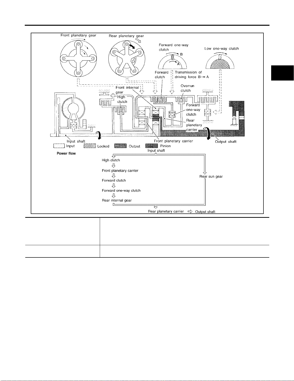
D3 and 33 Positions
OVERALL SYSTEM
[RE4F04B]
A
B
AT
D
E
F
G
● High clutch
● Forward clutch
● Forward one-way clutch
Overrun clutch
engagement conditions
WCIA0358E
Input power is transmitted to front planetary carrier throug h hig h clutc h. And front planetary
carrier is connected to rear internal gear by operation of forward clutch and forward one-way
clutch.
This rear internal gear rotation and another input (the rear sun gear ) acc om pany rear pla netary carrier to turn at the same speed.
3 and 33 : Selector lever is set in 3 position and throttle openin g is less than 3/16
D
H
I
J
K
L
M
Revision: July 2005 2006 Altima
AT-33
Page 56
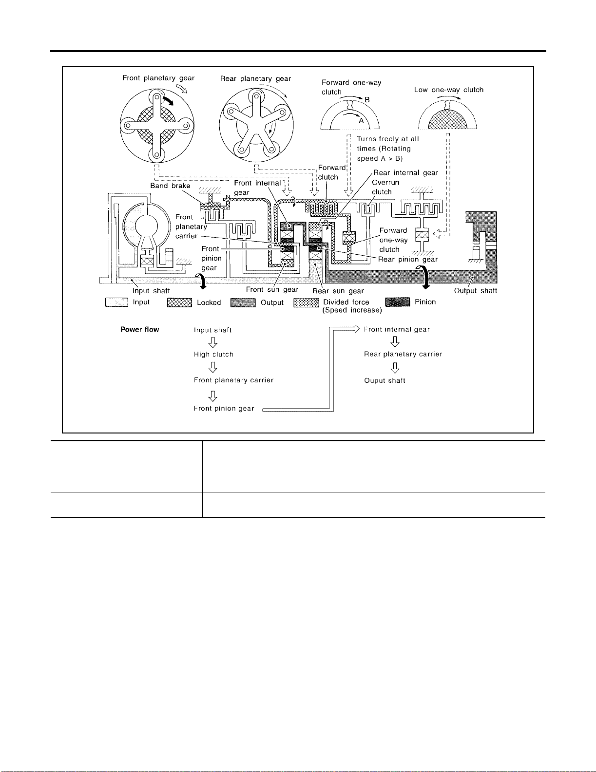
D4 Position
OVERALL SYSTEM
[RE4F04B]
WCIA0360E
● High clutch
● Brake band
● Forward clutch (Does not affect
power transmission)
Engine brake At D4 position, there is no one-way clutch in the power transmission line and engine brake
Input power is transmitted to front carrier through high clutch.
This front carrier turns around the sun gear which is fixed by brake band and makes front
internal gear (output) turn faster.
can be obtained when decelerating.
Revision: July 2005 2006 Altima
AT-34
Page 57
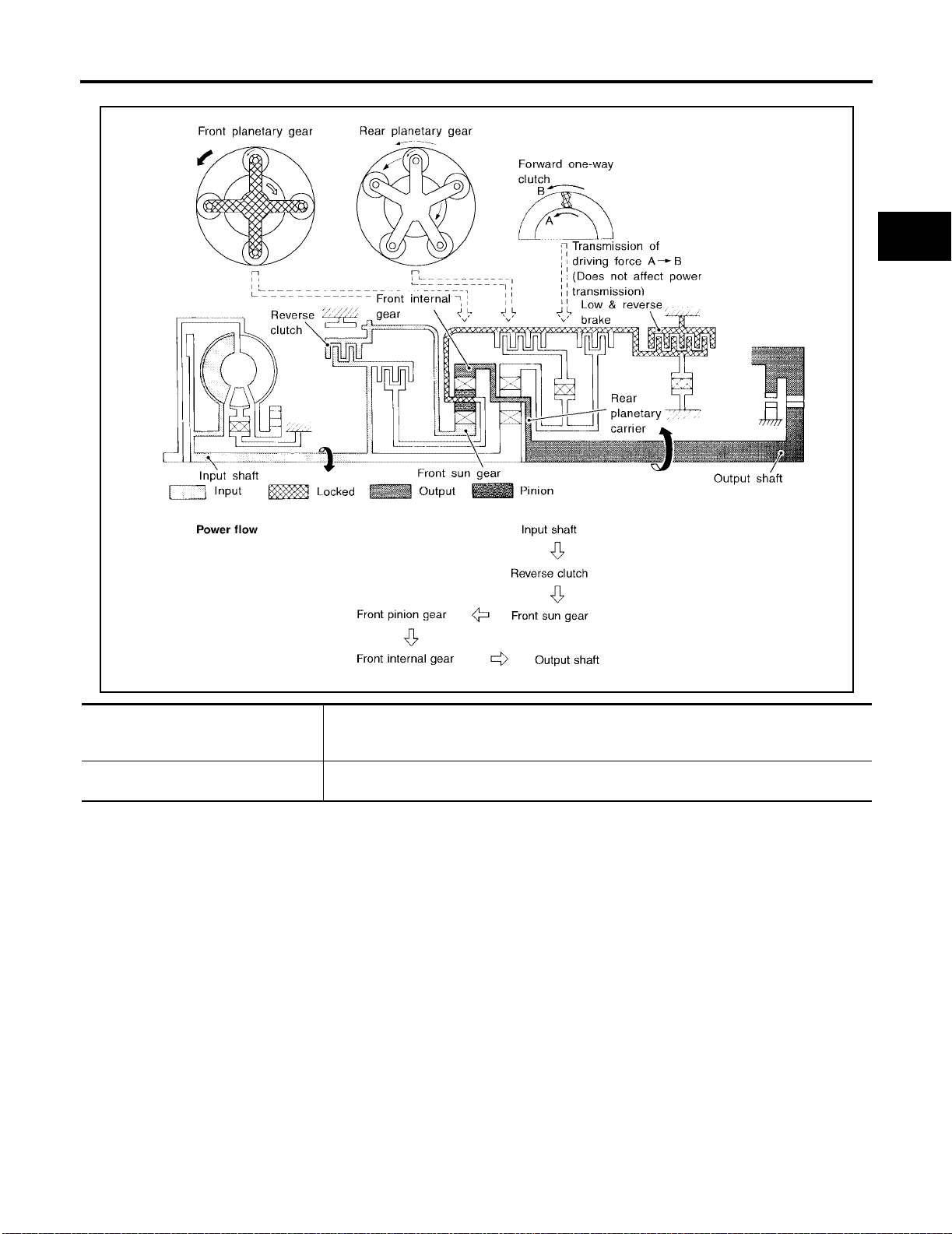
R Position
OVERALL SYSTEM
[RE4F04B]
A
B
AT
D
E
F
G
WCIA0359E
● Reverse clutch
● Low and reverse brake
Engine brake As there is no one-way clutch in the power transmission line, engine brake can be obtained
Front planetary carrier is stationary because of the operation of low and rever se bra ke.
Input power is transmitted to front sun gear through reverse clutch, which drives front internal gear in the opposite direction.
when dece l erating.
H
I
J
K
L
M
Revision: July 2005 2006 Altima
AT-35
Page 58
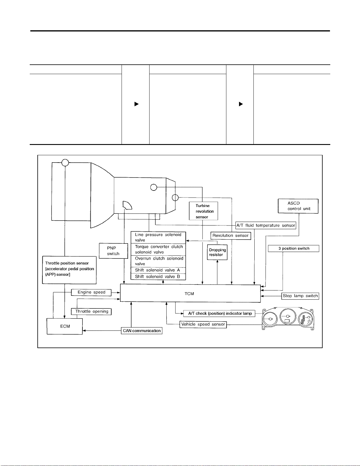
OVERALL SYSTEM
[RE4F04B]
Control System
ECS0095W
OUTLINE
The automatic transaxle senses ve hicle operating c onditions throug h various sensors . It always controls the
optimum shift position and reduces shifting and lock-up shocks.
SENSORS TCM ACTUATORS
Park/neutral position (PNP) switch
Accelerator pedal position (APP) signal
Engine speed signal
A/T fluid temperature sensor
Revolution sensor
Vehicle speed signal
3 position switch
ASCD control signal
Stop lamp swit ch
Turbine revolution sensor (power train
revolution sensor )
Shift control
Line pressure control
Lock-up control
Overrun clutch control
Timing control
Fail-safe control
Self-diagnosis
CAN communication line control
Shift solenoid valve A
Shift solenoid valve B
Overrun clutch solenoid valve
T orque converter clutch solenoid
valve
Line pressure solenoid valve
A/T check (position) indicator
lamp
CONTROL SYSTEM
LCIA0041E
Revision: July 2005 2006 Altima
AT-36
Page 59

OVERALL SYSTEM
[RE4F04B]
TCM FUNCTION
The function of the TCM is to:
● Receive input signals sent from various switches and sensors.
● Determine required line pressure, shifting point, lock-up operation, and engine brake operation.
● Send required output signals to t he respective sol enoids.
INPUT/OUTPUT SIGNAL OF TCM
Sensors and solenoid valves Function
Park/neutral position (PNP) switch Detects select lever position and sends a signal to TCM.
Detects throttle valve position and sends a signal to TCM . (CAN com munication)
Used as an auxiliary vehicle speed sensor. Sends a signal when revolution
sensor (installed on transaxle) malfunctions.
Sends a signal, which prohibits a shift to D
TCM.
Sends the cruise signal and D
control unit to TCM.
In CAN communication, control units are conn ect ed to 2 comm unication
lines (CAN H line, CAN L line) allowing a high rate of information transaxle
with less wiring.
Selects shifting point suited to driving conditions in relati on to a signa l sen t
from TCM.
Regulates (or decreases) line pressure suited to driving conditions in relation to a signal sent from TCM.
Regulates (or decreases) lock-up pr ess ure suited to driving conditions in
relation to a signal sent from TCM.
Controls an “engine brake” effect suited to driving conditions in relation to a
signal sent from TCM.
In CAN communication, control units are conn ect ed to 2 comm unication
lines (CAN H line, CAN L line) allowing a high rate of information transaxle
with less wiring.
4 (overdrive) cancellation signal from ASCD
4 (overdrive) position, to the
4 (lock-up).
Input
Output
Accelerator pedal position (APP) signal
Engine speed signal Receives signal from ECM and controls lock-up control solenoid valve.
A/T fluid temperature sensor Detects transaxle fluid temperature and sends a sign al to TC M.
Revolution sensor Detects output shaft rpm and sends a signal to TCM.
Vehicle speed sensor
3 position switch
ASCD control signal
Stop lamp swit ch Send the lo ck-up release signal t o the TCM at time of D
CAN communication
Shift solenoid valve A/B
Line pressure solenoid valve
Torque converter clutch solenoid valve
Overrun clutch solenoid valve
A/T check (position) indicator lamp Shows TCM faults, when A/T control componen ts malfunctio n.
CAN communication
A
B
AT
D
E
F
G
H
I
J
K
L
Revision: July 2005 2006 Altima
AT-37
M
Page 60
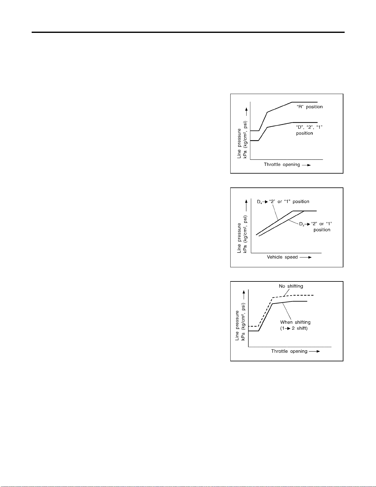
OVERALL SYSTEM
[RE4F04B]
Control Mechanism
ECS0095X
LINE PRESSURE CONTROL
TCM has various line pressure control characteristics to meet the driving conditions.
An ON-OFF duty signal is sent to the line pressure solenoid valve based on TCM characteristics.
Hydraulic pr es sure o n t h e c lut ch an d br ak e is el ect ro nic al ly co nt rol l ed t hr oug h t h e l ine pr e ssur e so leno id va l ve
to accommodate engine torque. This results in smooth shift operation.
Normal Control
The line pres sure to thr ottl e open ing char acte rist ics i s set f or s uit able
clutch operatio n.
SAT003J
Back-up Control (Engine brake)
If the selector lev er is shifted to 2 position w hile driving in D4 (O/D)
or D
3 , great driving force is applied to the clutch inside the transmis-
sion. Clutch operating pressure (line pressure) must be increased to
deal with this driving force.
SAT004J
During Shift Change
The line pressure is temporari ly reduce d correspon ding to a c hange
in engine torqu e w h en s hi ftin g ge ars (t ha t is , w he n t he s hif t s ol en oi d
valve is switched for clutch operation) to reduce shifting shock.
SAT005J
At Low Fluid Temperature
● Fluid viscosity and frictional characteristics of the clutch facing change with fluid temperature. Clutch
engaging or band-contacting pressure is compensated for, according to fluid temperature, to stabilize
shifting quality.
Revision: July 2005 2006 Altima
AT-38
Page 61
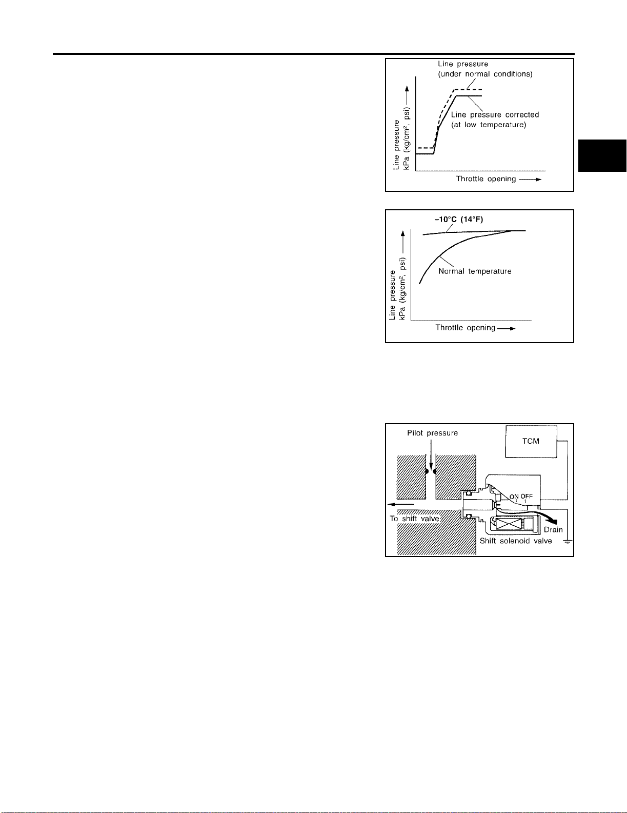
OVERALL SYSTEM
● The line pressure is reduced below 60°C (140°F) to prevent
shifting shock due to low viscosity of automatic transaxle fluid
when temperature is low.
● Line pressure is increased to a maximum irrespective of the
throttle openin g when fluid temperature dro ps to −10°C (14°F).
This pressure rise is adopted to prevent a delay in clutch and
brake operation due to extreme drop of fluid viscosity at low
temperature.
[RE4F04B]
A
B
AT
SAT006J
D
E
F
G
SAT007J
SHIFT CONTROL
The shift is regulated entirely by electronic control to accommodate vehicle speed and varying engine operations. This i s accomplished by e lectrical signals transm itted by the revolution sensor and the ECM (throttle
opening). This results in improved acceler ation performan c e and fuel economy.
Control of Shift Solenoid Valves A and B
The shift sole noid valve perfor ms simple ON-OFF op eration. When
set to ON, the drain circu it cl os es and pilo t pre ssure is ap pl ied to the
shift valve.
The TCM activa tes shift solenoid valv es A and B according t o signals from the ECM (throttle opening) and revolution sensor to select
the optimum gear p osition on the basis of the shift sc hedule me morized in the TCM.
SAT008J
H
I
J
K
L
M
Revision: July 2005 2006 Altima
AT-39
Page 62
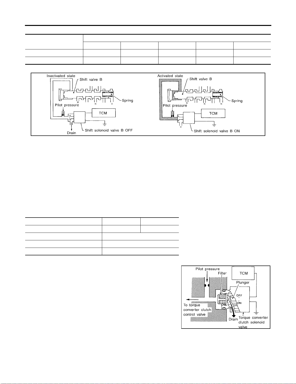
OVERALL SYSTEM
[RE4F04B]
Relation between shift solenoid valves A and B and gear positions
Shift solenoid valve
A ON (C los ed) OFF (Open ) OFF (Open) ON (Closed) ON (Closed)
B ON (C los ed) O N (Clo sed) OFF (Ope n) OFF (Open) ON (Closed)
1 , 21 , 11 D2 , 22 , 12 D3 D4 (O/D) N-P
D
Control of Shift Valves A and B
Pilot pressure generated by the operation of shift solenoid valves A and B is applied to the end face of shift
valves A and B.
The drawing above shows the operation of shift valve B. When the shift solenoid valve is ON, pilot pressure
applied to the end face of the shi ft valve overcom es spring force , moving the valve upward.
Gear position
SAT009J
LOCK-UP CONTROL
The torque converter clutch piston in the torque converter is locked to eliminate torque converter slip to
increase powe r transmis sion effici ency. The solenoid valve is contro lled by an ON-O FF duty signal sent from
the TCM. The signal is converted to an oil pressure signal which controls the lock-up piston.
Conditions for Lock-up Operation
When vehicle is driven in 4th gear position, vehicle speed and throttle opening are detected. If the detected
values fall within the loc k-u p zo ne mem ori ze d in the TC M, lo ck -up is perf orm ed.
Selector lever D position 3 position
Gear position D
Vehicle speed sensor More than set value
ECM (throttle opening) Less than set opening
A/T fluid temperature sensor Mo re than 40 °C (104°F)
4 3
Torque Converter Clutch Solenoid Valve Control
The torque converter clutch solenoid valve is controlled by the TCM.
The plunger closes the drain circuit during the OFF period, and
opens the circuit during the ON period. If the percentage of OFF-time
increases in o ne cycle, th e pilot pr essure drain tim e is reduce d and
pilot pressure remains hi gh.
SAT010J
Revision: July 2005 2006 Altima
AT-40
Page 63
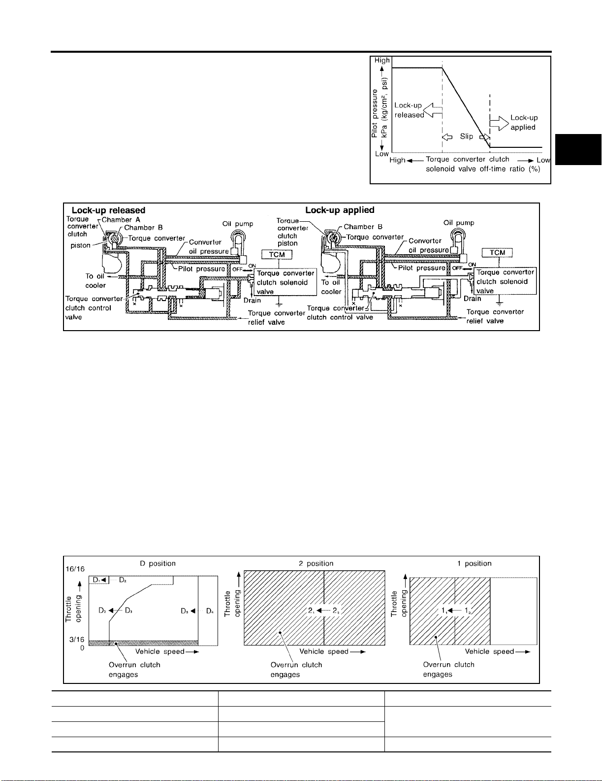
OVERALL SYSTEM
The torque converter clutch piston is designed to slip to adjust the
ratio of ON-OFF, thereby reducing lock-up shock.
OFF-time INCREASING
↓
Amount of drain DECREASING
↓
Pilot pressure HIGH
↓
Lock-up RELEASING
Torque Converter Clutch Control Valve Operation
[RE4F04B]
A
B
AT
SAT011J
D
E
F
G
AAT155A
LOCK-UP RELEASED
The OFF-duration of the torque converter clutch solenoid valve is long, and pilot pressure is high. The pilot
pressure pushes the end face of the torque converter clutch control valve in combination with spring force to
move the valv e t o th e le ft . A s a r esul t , conv er t er p r es sur e i s a pp lie d t o ch amb er A (to r qu e c on ve rte r cl ut c h p is ton release side). According ly, the torque converter clutch piston remains unlocked.
LOCK-UP APPLIED
When the OFF-duration of the torque converter clutch solenoid valve is short, pilot pressure drains and
becomes low. Accordingly, the control valve moves to the right by the pilot pressure of the other circuit and
converter pressure. A s a result, converter pressure is app lied to chamber B, keeping the torq ue converter
clutch piston applied.
Also smooth lock-up is provided by transient application and release of the lock-up.
OVERRUN CLUTCH CONTROL (ENGINE BRAKE CONTROL)
Forward one-way clutch is used to reduce shifting shocks in downshifting operations. This clutch transmits
engine torque to the wheels. However, drive force from th e wheels is not transm itted to the engine because
the one-way clutch rotates idle. This means the engine brake is not effective.
The overrun clutch operates when the engine brake is needed.
Overrun Clutch Operating Conditions
H
I
J
K
L
M
SAT014J
Selector lever position Gear position Throttle opening
DD
22
111 , 12 At any position
Revision: July 2005 2006 Altima
1 , D2 , D3
1 , 22
AT-41
Less than 3/16
Page 64
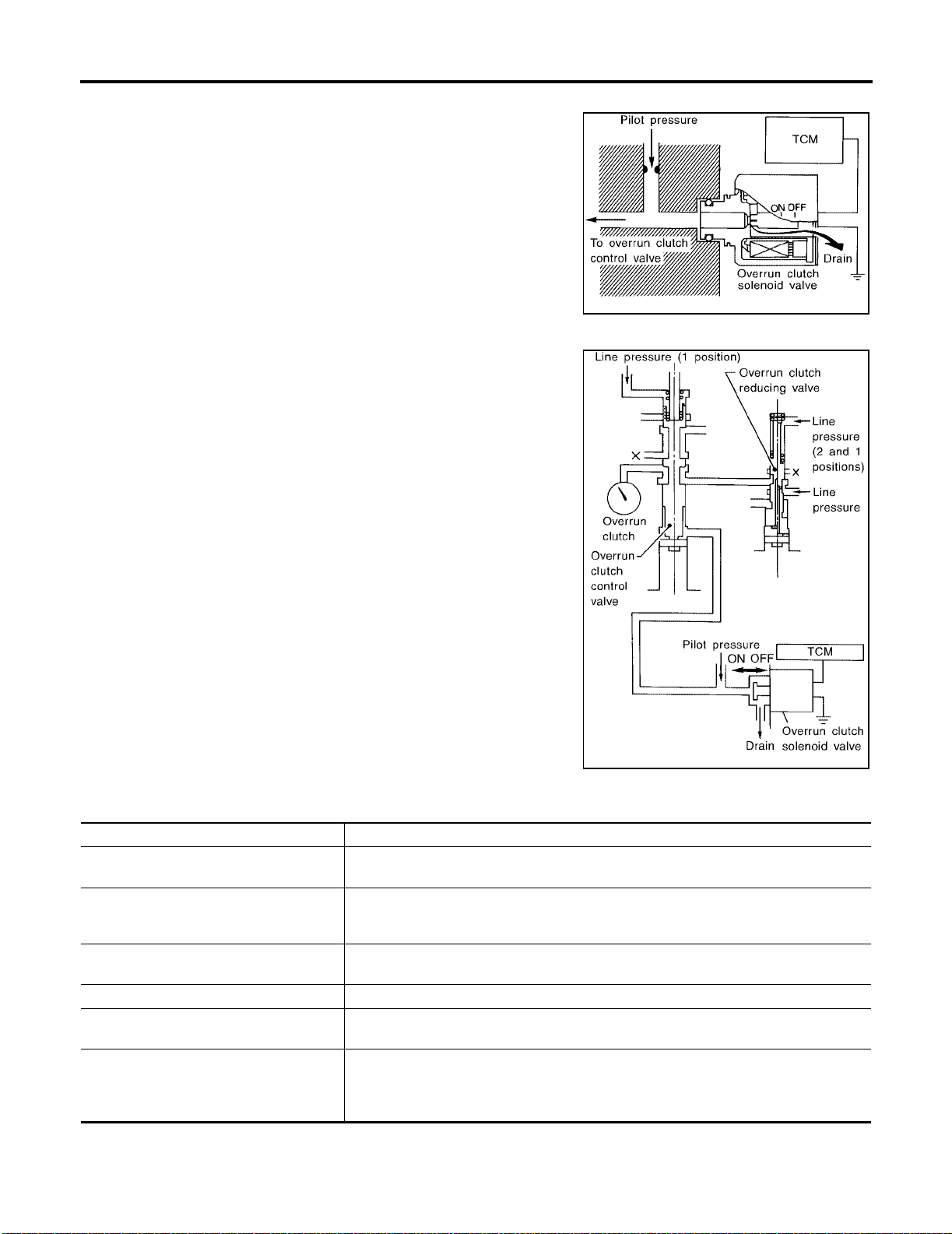
OVERALL SYSTEM
Overrun Clutch Solenoid Valve Control
The overrun clutch solenoid valve is operated by an ON-OFF signal
transmitted by the TCM to provide overrun clutch control (engine
brake control).
When this solenoid valve is ON, the pilot pressure drain port closes.
When it is OFF, the drain port opens.
During the solenoid valve ON pilot pressure is applied to the end
face of the overrun clutch control valve.
Overrun Clutch Control Valve Operation
When the solenoid valve is ON, pilot pressure is applied to the overrun clutch control va lve. This pushes up the overrun clutch control
valve. The line pressure is then shut off so that the clutch does not
engage.
When the solenoid valve is OFF, pilot pressure is not generated. At
this point, the overrun clutch control valve moves downward by
spring force. As a result, overrun clutch operation pressure is provided by the overrun clutch reducing valve. This causes the overrun
clutch to engage .
In the 1 position, the overrun clutch control valve remains pushed
down so that the overrun clutch i s engaged at all times.
[RE4F04B]
SAT015J
SAT016J
Control Valve
ECS0095Y
FUNCTION OF CONTROL VALVES
Valve name Function
Pressure regulator valve, plug and sleeve
plug
Pressure modifier valve and sleeve Used as a signal supplementary valve to the pressure regulator valve. Regulates pres-
Pilot valve Regulates line pressure to maintain a constant pilot pressure level which controls lock-up
Accumulator control valve Regulates accumulator back-pressure to pressure suited to driving conditions.
Manual valve Directs line pressure to oil circuits corresponding to select positions.
Shift valve A Simultaneously switches three oil circuits using output pressure of shift solenoid valve A
Revision: July 2005 2006 Altima
Regulates oil discharged from the oil pump to provid e opt imum line press ure for all driving conditions.
sure-modifier pressure (signal pressure) which controls optimum line pressu re for all
driving conditions.
mechanism, overrun clutch, shift timing.
Hydraulic pressure drains when the shift le ver is in Neutral .
to meet driving conditions (vehicle speed, throttle opening, etc.).
Provides automatic downshifting and up-shi f ting ( 1st → 2nd → 3rd → 4th gears/4th →
3rd → 2nd → 1st gears) in combination with shift valve B.
AT-42
Page 65

OVERALL SYSTEM
[RE4F04B]
V alve name Function
Shift valve B Simultaneously switches two oil circuits using output pressure of shift solenoid valve B in
relation to driving conditions (vehicle speed, throttle opening, etc.).
Provides automatic downshifting and up-shifting (1st → 2nd → 3rd → 4th gears/4th →
3rd → 2nd → 1st gears) in combinat i on w ith shif t valve A.
Overrun clutch control valve Switches hydraulic circuits to prevent engagement of the overrun clutch simultaneously
with application of the brake band in D
engages during D
“1” reducing valve Reduces low & reverse brake pressure to dampen engine-brake shock when down-shift-
ing from the 1 position 12 to 11 .
Overrun clutch reducing valve Reduces oil pressur e di rec te d to the overrun clutch and prevents engine-brake shock.
In 1 and 2 positions, line pressure acts on the overrun clutch re duci ng va lv e to incr ease
the pressure-regulating point, with resul tant engi ne bra ke capabilit y.
Torque converter relief valve Prevents an excessive rise in torque converter pressure.
Torque converter clutch control valve, plug
and sleeve
1-2 accumulator valve and piston Dam pens the shock encountered when 2nd ge ar ban d ser vo cont r acts, and pro vi des
3-2 timing valve Switches the pace that oil pressure is released depending on vehicle speed; maximizes
Shuttle valve Determines if the overrun clutch solenoid valve should control the 3-2 timing valve or the
Cooler check valve At low speeds and with a small load when little heat is generated, saves th e volume of
Activates or inactivates the lock-up function.
Also provides smooth lock-up through transi ent application and release of the lock-up
system.
smooth shifting.
the high clutch release timing, and allows for sof t down shifting.
overrun clutch control valve and switches between the two.
cooler flow, and stores the oil pressure for lock up.
4 .)
4 . (Interlocking occurs if the overrun clutch
A
B
AT
D
E
F
G
H
K
M
I
J
L
Revision: July 2005 2006 Altima
AT-43
Page 66

ON BOARD DIAGNOSTIC SYSTEM DESCRIPTION
[RE4F04B]
ON BOARD DIAGNOSTIC SYSTEM DESCRIPTION PFP:00000
Introduction
ECS0095Z
The A/T system has two self-diagn ostic systems.
The first is the em is si on - rel at ed o n bo ar d diag no st i c sy stem (O BD -I I) pe rfo r med by th e T CM ( t ran sa xl e c on tro l
module) in comb ination with the ECM . The malfunction is indicated by the MIL (m alfunction indica tor lamp)
and is stored as a DTC in the ECM memor y but not the TCM memory.
The second is the TCM origi nal self-diagno sis indicated by th e A/T check (positio n) indicator lamp. The malfunction is stored in the TCM memory. The detected items are overlapped with OBD-II self-diagnostic items.
For details, refer to AT-44, "
OBD-II Function for A/T System
OBD-II Function for A/T System" .
ECS00960
The ECM provides emission-related on board diagnostic (OBD-II) functions for the A/T system. One function
is to receive a signal from the TCM used with OBD-related parts of the A/T system. The signal is sent to the
ECM when a mal function occurs in the corre sponding OBD-related part. The other function is to ind icate a
diagnostic result by means of the MIL (malfunction indicator lamp) on the instrument panel. Sensors, switches
and solenoid valves are used as sensing elements.
The MIL automatically illuminates in One or Two Trip Detection Logic when a malfunction is sensed in relation
to A/T system parts.
One or Two Trip Detection Logic of OBD-II
ECS00961
ONE TRIP DETECTION LOGIC
If a malfunction is sensed during the fir s t test drive, the MIL will illuminate and t he malfunctio n will be store d in
the ECM memory as a DTC. The TCM is not provided with such a memory function.
TWO TRIP DETECTION LOGIC
When a malfuncti on is sensed during the fi rst test drive, it is stored in the ECM memory as a 1st trip DT C
(diagnostic trouble code) or 1st trip freeze frame data. At this point, the MIL will not illuminate. — First Trip
If the same malf unction as that experien ced during the first test drive is sense d during the second te st drive,
the MIL will illuminate. — Second Trip
A/T-related parts for which the MIL illuminates during the first or second test drive are listed below.
Items
Shift solenoid valve A — DTC: P0750 X
Shift solenoid valve B — DTC: P0755 X
Accelerator pedal position (APP) sensor — DTC: P1705 X
Except above X
One trip de tection Two trip d e tection
MIL
The “trip” in the “One or Two Trip Detection Logic” means a driving mode in which self-diagnosis is performed
during vehicle operation.
OBD-II Diagnostic Trouble Code (DTC)
ECS00962
HOW TO READ DTC AND 1ST TRIP DTC
DTC and 1st trip DTC can be read by the following methods.
( With CONSULT-II or GST) CONSULT-II or GST (Generic Scan Tool) Examples: P0705, P0710,
P0720, P0725, etc.
These DTCs are prescribed by SAE J2012.
(CONSULT-II also displays the malfu nctioning compo nent or system.)
● 1st trip DTC No. is the same as DTC No.
● Output of the diagnostic troubl e code indi cates that th e indicate d circuit has a malfuncti on. How-
ever, in case of the Mode II and GST they do not indicate whether the malfunction is still occurring
or occurred in the past and returned to normal.
CONSULT-II can identify them as shown below. Therefore, using CONSULT-II (if available) is recommended.
Revision: July 2005 2006 Altima
AT-44
Page 67
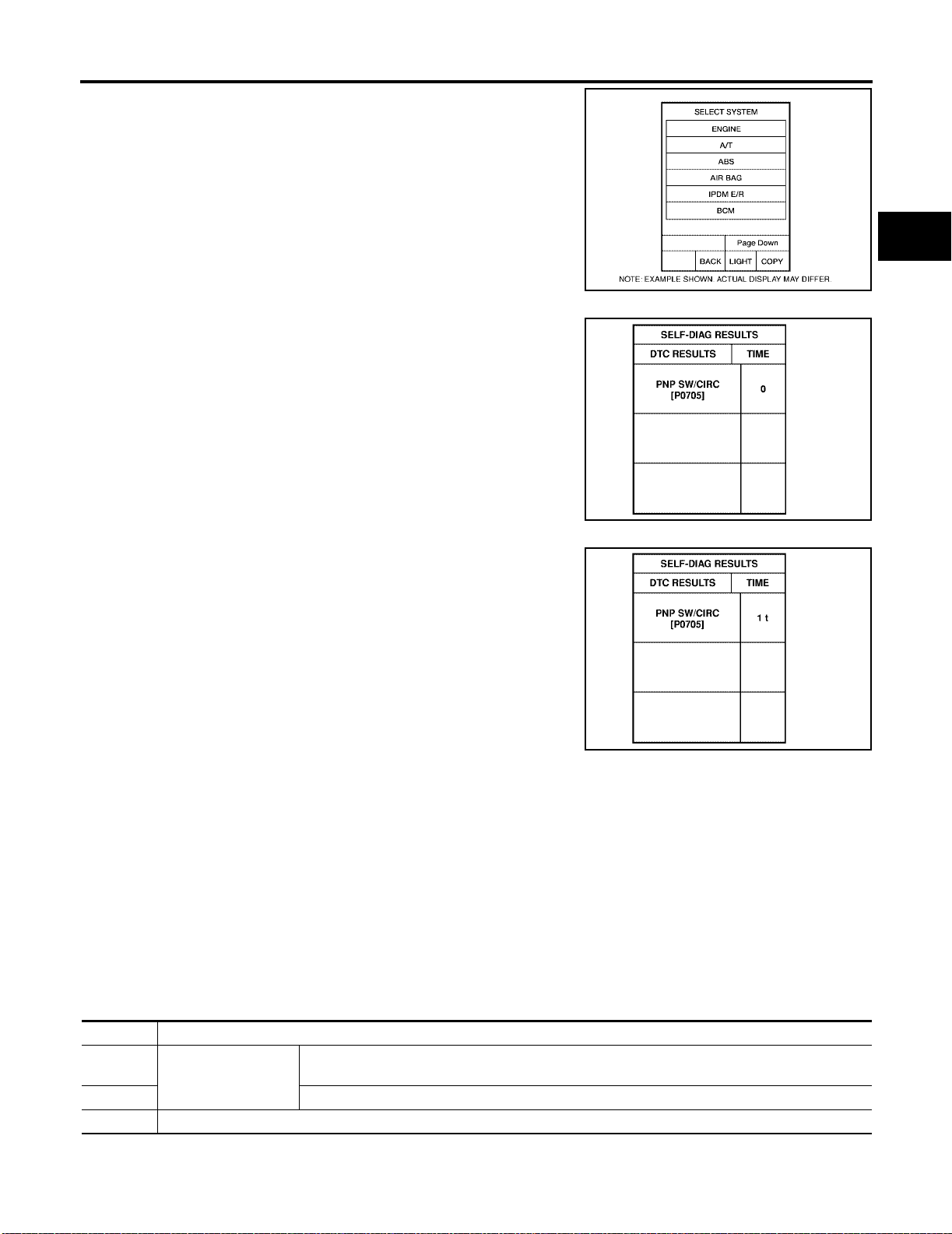
ON BOARD DIAGNOSTIC SYSTEM DESCRIPTION
A sample of CONSULT-II display for DTC and 1st trip DTC is shown
in the following page. DTC or 1st trip DTC o f a malfunction is displayed in “SELF DIAGNOSIS” mode for “ENGINE” with CONSULTII. Time data indicates how many times the vehicle was driven after
the last detection of a DTC.
If the DTC is being detected currently, the time data will be “0”.
[RE4F04B]
A
B
AT
BCIA0030E
D
E
F
G
SAT015K
If a 1st trip DTC is stored in the ECM, the time data will be “1t”.
SAT016K
Freeze Frame Data and 1st Trip Freeze Frame Data
The ECM has a me mory function, whic h stores the driving c ondition such as fuel s ystem status, calcul ated
load value, engin e coolant temperature, short te rm fuel trim, long term fuel trim, engin e speed and vehicle
speed at the moment the ECM detects a malfunction.
Data which are stored in the ECM memory, along with the 1st trip DTC, are called 1st trip freeze frame data,
and the data, s tored to gether with t he DTC data, a re call ed freez e fram e data an d disp layed on CO NSULT-II
or GST. The 1st trip freeze frame data can only be displayed on the CONSULT-II screen, not on the GST. For
details, refer to ! Hyper-link Error ! .
Only one set of freeze frame data (either 1st trip freeze frame data of freeze frame data) can be stored in the
ECM. 1st trip freeze frame data is stored in the ECM memory along with the 1st trip DTC. There is no priority
for 1st trip freeze fr ame data and it is update d each time a different 1st trip DTC is det ected. However, once
freeze frame data (2nd trip detection/MIL on) is stored in the ECM memory, 1st trip freeze frame data is no
longer stored. R eme mber, only one set of free ze fra me da ta can be stored in the ECM . The ECM has th e following pri orities to update the data.
Priority Items
1 Freeze frame data Misfire — DTC: P0300 - P0306
Fuel Injection System Function — DTC: P0171, P0172, P0174, P0175
2 Except the above items (Inc lu des A/T relat ed item s)
3 1st trip freeze fram e data
H
I
J
K
L
M
Both 1st trip freeze frame data and freeze frame data (along with the DTCs) are cleared when the ECM memory is erased.
Revision: July 2005 2006 Altima
AT-45
Page 68

ON BOARD DIAGNOSTIC SYSTEM DESCRIPTION
[RE4F04B]
HOW TO ERASE DTC
The diagnostic trouble code can be erased by CONSULT-II, GST or ECM DIAGNOSTIC TEST MODE as
described following.
● If the battery terminal is disconnected, the diagnostic trouble code will be lost within 24 hours.
● When you eras e th e DTC , u si ng C ON SU LT-II o r GST is ea sier a nd q ui cke r than swi tc hi ng t he m od e
selector on the ECM.
The following em ission-related diagnostic in formation is cleared from the ECM me mory when erasing DTC
related to OBD-II. For details, refer to ! Hyper-link Error ! .
● Diagnostic trouble codes (DTC)
● 1st trip diagnostic trouble codes (1st trip DTC)
● Freeze frame data
● 1st trip freeze frame data
● System readiness test (SRT) co des
● Test values
HOW TO ERASE DTC (WITH CONSULT-II)
● If a DTC is displayed for both ECM and TCM, it needs to be erased for both ECM and TCM.
1. If the ign iti on s witc h stays ON aft er re pair work , b e su re to turn ignition s w itc h O FF on ce . Wait at le as t 10
seconds and then turn it ON (engine stopped) again.
2. Turn CONSULT-II “ON” and tou ch “A/T”.
3. Touch “SELF-DIAG RESULTS”.
4. Touch “ERASE”. (The DTC in the TCM will be erased.) Then touch “BACK” twice.
5. Touch “ENGINE”.
6. Touch “SELF-DIAGNOSIS RESULTS”.
Revision: July 2005 2006 Altima
AT-46
Page 69
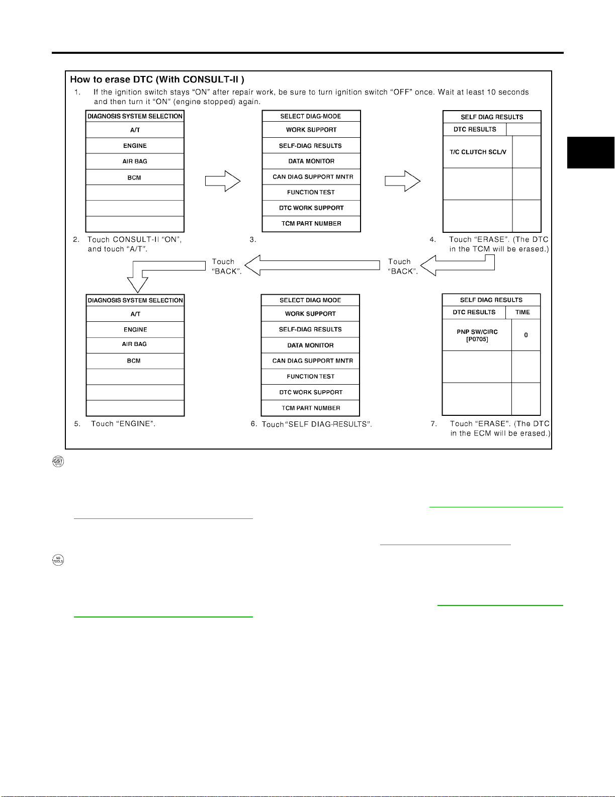
ON BOARD DIAGNOSTIC SYSTEM DESCRIPTION
7. Touch “ERASE”. (The DTC in the ECM will be erased.)
[RE4F04B]
A
B
AT
D
E
F
G
WCIA0361E
HOW TO ERASE DTC (WITH GST)
1. If the ignition switch stays ON after repair work, be sure to turn ignition switch OFF once. Wait at least 10
seconds and then turn it ON (engine stopped) again.
2. Perform “OBD-II SELF-DIAGNOSTIC PROCEDURE (No Tools)”. Refer to AT- 5 9, "
OBD-II SELF-DIAGNOSTIC PROCEDURE (NO TOOLS)" . (The engine warm-up step can be skipped when performing the
diagnosis only to erase the DTC.)
3. Select Mode 4 with Generic S can Tool (GST). For details, refer to EC-64, "
How to Erase DTC" .
HOW TO ERASE DTC (NO TOOLS)
1. If the ignition switch stays ON after repair work, be sure to turn ignition switch OFF once. Wait at least 10
seconds and then turn it ON (engine stopped) again.
2. Perform “TCM SELF-DIAGNOSTIC PROCEDURE (NO TOOLS)”. Refer to AT-60, "
NOSTIC PROCEDURE (NO TOOLS)" . (The engine warm-up step can be skipped when performing the
diagnosis only to erase the DTC.)
TCM SELF-DIAG-
H
I
J
K
L
M
Revision: July 2005 2006 Altima
AT-47
Page 70
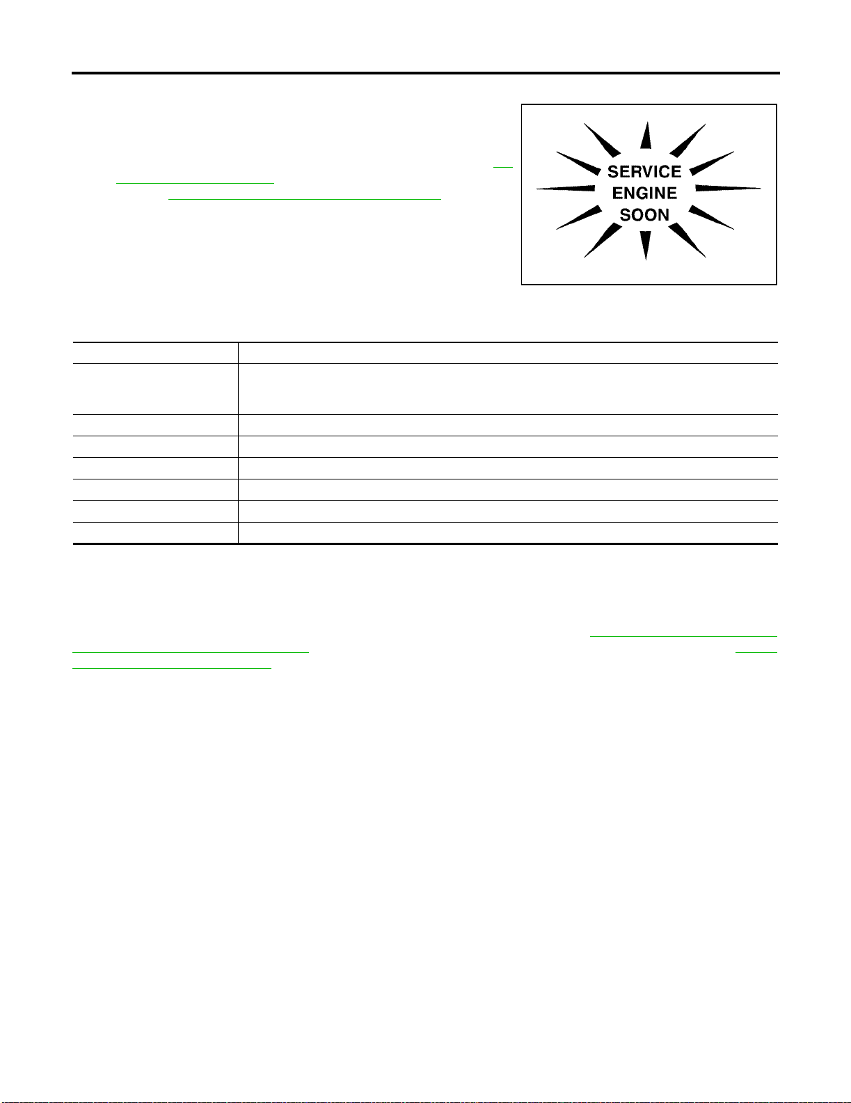
ON BOARD DIAGNOSTIC SYSTEM DESCRIPTION
[RE4F04B]
Malfunction Indicator Lamp (MIL)
1. The malfunction indicator lamp will light up when the ignition
switch is turned ON without the engine running. This is for
checking the lamp.
● If the malfunction indicator lamp does not light up, refer to DI-
31, "WARNING LAMPS" .
(Or see EC-66, "
Malfunction Indicator Lamp (MIL)" .)
2. When the engine is started, the malfunction indicator lamp
should go off.
If the lamp remains on, the on board diagnostic system has
detected an emission-related (OBD-II) malfunction. For details,
refer to ! Hyper-link Error ! .
CONSULT-II Function (TCM)
CONSULT-II can display each diagnostic item using the diagnostic test modes shown following.
TCM diagnostic mode Description
Supports inspections and adjustments. Commands are transmitted to the TCM for setting the status
WORK SUPPORT
SELF-DIAG RESULTS Di splays TCM self-diagnosis results.
DATA MONITOR Displays TCM input/output data in real time.
CAN DIAG SUPPORT MNTR The result of transmit/re ceive di agnosis of CAN communication can be read.
ACTIVE TEST Operation of electrical loads can be checked by sending drive signal to them.
FUNCTION TEST Conducted by CONSULT-II instead of a technician to determine whether each system is "OK" or "NG".
ECU PART NUMBER TCM part number can be read.
suitable for required operation, input/output si gnals ar e received from the TCM and received data is
displayed.
ECS00963
SAT964I
ECS00964
CAUTION:
If CONSULT-II is used with no connection of CONSULT-II CONVERTER, malfunctions might be
detected in self-diagnosis depending on control unit which carries out CAN communication.
After performing “SELF-DIAGNOSTIC PROCEDURE (WITH CONSULT-II)” (AT-49, "
SELF-DIAGNOSTIC
PROCEDURE (WITH CONSULT-II)" ), plac e check marks for resul ts on the “Diagnostic Worksh eet”, AT-65,
"DIAGNOSTIC WORKSHEET" . Reference pages are provide following the items.
NOTICE:
1. The CONSULT-II elec tri cal ly dis play s shi ft tim ing an d lock -up t imin g (tha t is, op era tio n timi ng of eac h sol e-
noid).
Check for time difference between actual shift timing and the CONSULT-II display. If the difference is
noticeable, me chan ical parts (exc ept s olen oids , sens ors, e tc .) may be ma lfunc tion ing. C hec k me chan ical
parts using applicabl e diagnostic procedures.
2. Shift schedule (which implies gear position) displayed on CONSULT-II and that indicated in Service Man-
ual may differ slightly. This occurs because of the following reasons:
– Actual shift schedule has more or less tol erance or allowance,
– Shift schedule indicated in Service Manual refers to the point where shifts start, and
– Gear position displayed on CONSULT-II indicates the point where shifts are completed.
3. Shift solenoid valve “A” or “B” is displayed on CONS ULT-II at the start of shifti ng. Gear position is dis -
played upon completion of shifting (which is computed by TCM).
4. Additional CONSULT-II information can be found in the Operation Manual supplied with the CONSULT-II
unit.
Revision: July 2005 2006 Altima
AT-48
Page 71
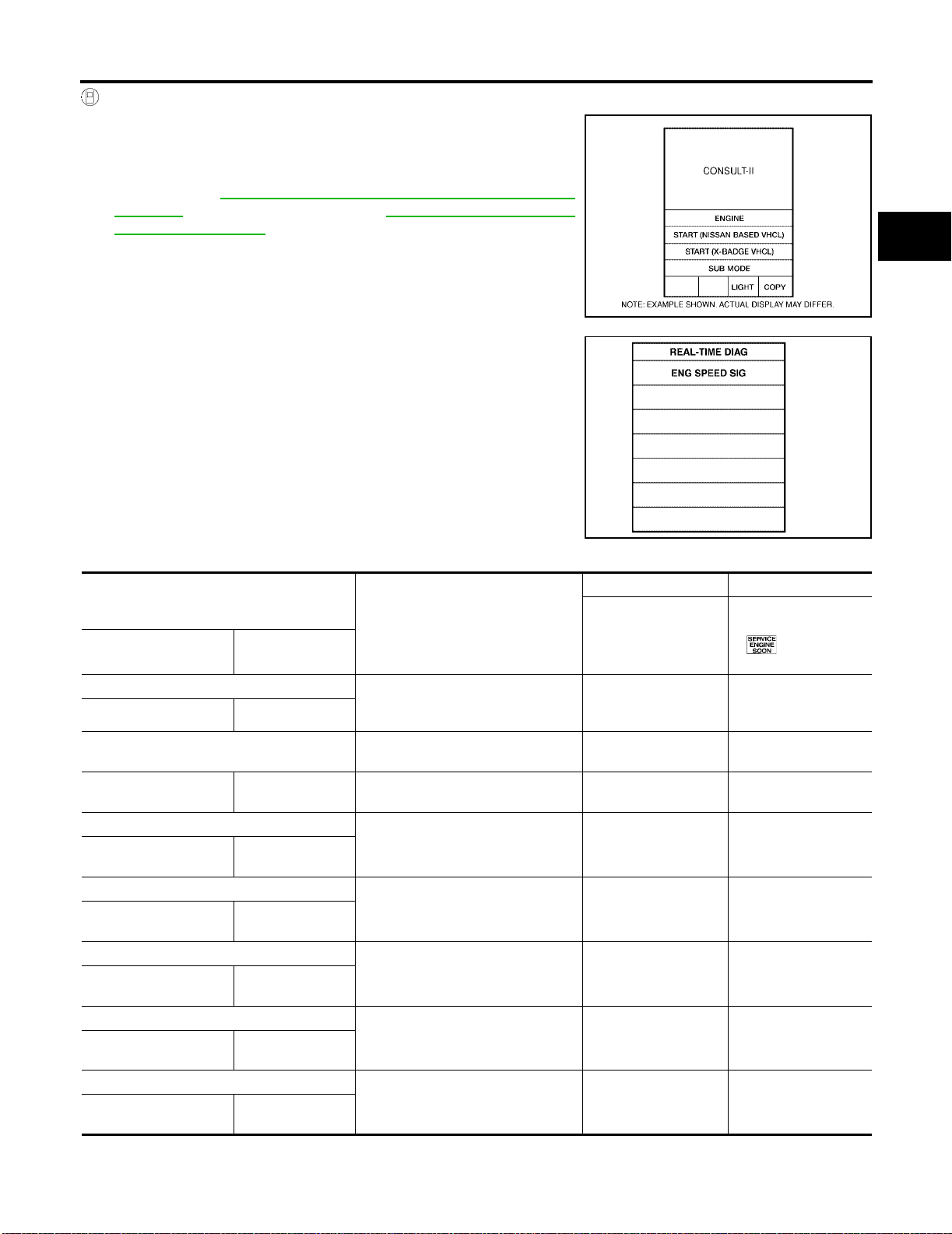
ON BOARD DIAGNOSTIC SYSTEM DESCRIPTION
SELF-DIAGNOSTIC PROCEDURE (WITH CONSULT-II)
1. Touch on CONSULT-II, touch "START (NISSAN BASED
VHCL)", and t ouch “ENGINE” for OBD-II detected items or touch
“A/T” for TCM self-diagnosis .
If A/T is not displayed, check TCM power supply and ground circuit. Refer to AT-107, "
SUPPLY" . If result is NG, refer to PG-4, "POWER SUPPLY
ROUTING CIRCUIT" .
TROUBLE DIAGNOSIS FOR POWER
[RE4F04B]
A
B
AT
2. Touch “SELF DIAG RESULTS”.
Display shows malfunction experienced since the last erasing
operation.
CONSULT-II performs “Real Time Diagnosis”.
Also, any malfunction detected while in this mode will be displayed at real time.
SELF-DIAGNOSTIC RESULT TEST MODE
Detected items
(Screen terms for CONSULT-II, “SELF
DIAGNOSIS” test mode)
“A/T”“ENGINE”
Park/neutral position (PNP) switch circuit
— PNP SW/CIRC
Revolution sensor
VHCL SPEED SEN·A/T
Vehicle speed sensor (Meter)
VHCL SPEED
SEN·MTR
A/T 1st gear function
—
A/T 2nd gear function
—
A/T 3rd gear function
—
A/T 4th gear function
—
VEH SPD SEN/
CIR AT
—
A/T 1ST GR
FNCTN
A/T 2ND GR
FNCTN
A/T 3RD GR
FNCTN
A/T 4TH GR
FNCTN
Malfunction is detected when...
● TCM does not receive the corre ct
voltage signal (based on the gear
position) from the switch.
● TCM does not receive the proper
voltage signal from the sensor.
● TCM does not receive the proper
voltage signal from the sensor.
● A/T cannot be shifted to the 1st
gear position even if electrical circuit is good.
● A/T cannot be shifted to the 2nd
gear position even if electrical circuit is good.
● A/T cannot be shifted to the 3rd
gear position even if electrical circuit is good.
● A/T cannot be shifted to the 4th
gear position even if electrical circuit is good.
TCM self-diagnosis OBD-II (DTC)
Available by A/T check
(position) indicator
lamp or “A/T” on
CONSULT-II
— P0705
XP0720
X —
— P0731*1
— P0732*1
— P0733*1
— P0734*1
Available by malfunction indicator lamp*2,
“ENGINE” on
CONSULT-II or GST
BCIA0029E
SAT987J
D
E
F
G
H
I
J
K
L
M
Revision: July 2005 2006 Altima
AT-49
Page 72
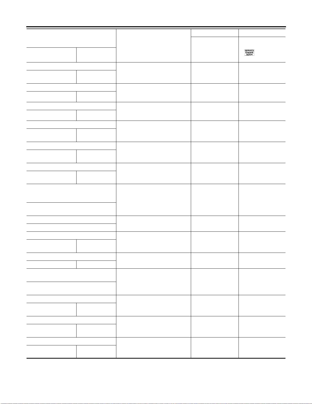
ON BOARD DIAGNOSTIC SYSTEM DESCRIPTION
[RE4F04B]
Detected items
(Screen terms for CONSULT-II, “SELF
DIAGNOSIS” test mode)
“A/T”“ENGINE”
A/T TCC S/V function (lock-up)
—
A/T TCC S/V
FNCTN
Shift solenoid valve A
SHIFT SOLENOID/V A SFT SOL A/CIRC
Shift solenoid valve B
SHIFT SOLENOID/V B SFT SOL B/CIRC
Overrun clutch solenoid valve
OVERRUN CLUTCH S/VO/R CLUCH SOL/
CIRC
T/C clutch solenoid valve
T/C CLUTCH SOL/V
TCC SOLENOID/
CIRC
Line pressure solenoid valve
LINE PRESSURE S/V
L/PRESS SOL/
CIRC
Throttle position sensor [accelerator pedal
position (APP) sensor]
THROTTLE POSI SEN TP/SEN/CIRC A/T
Malfunction is detected when...
● A/T cannot perform lock-up even if
electrical circuit is good.
● TCM detects an improper voltage
drop when it tries to operate the
solenoid valve.
● TCM detects an improper voltage
drop when it tries to operate the
solenoid valve.
● TCM detects an improper voltage
drop when it tries to operate the
solenoid valve.
● TCM detects an improper voltage
drop when it tries to operate the
solenoid valve.
● TCM detects an improper voltage
drop when it tries to operate the
solenoid valve.
● TCM receives an excessively low
or high voltage from this sensor
TCM self-diagnosis OB D- II (DTC)
Available by A/T check
(position) indicator
lamp or “A/T” on
CONSULT-II
Available by malfunction indicator lamp*2,
“ENGINE” on
CONSULT-II or GST
— P0744*1
X P0750
X P0755
X P1760
X P0740
X P0745
X P1705
Engine speed signal
ENGINE SPEED SIG
A/T fluid temperature sensor
BATT/FLUID TEM P
SEN
ATF TEMP SEN/
CIRC
Engine control
A/T COMM LINE —
Turbine revolution sensor
TURBINE REV
TCM (RAM)
CONTROL UNIT
(RAM)
TCM (ROM)
CONTROL UNIT
(ROM)
TCM (EEP RO M)
CONT UNIT(EEP
ROM)
—
—
—
● TCM does not receive the proper
voltage signal from the ECM.
● TCM receives an excessively low
or high voltage from the sensor.
● The ECM-A/T communication line
is open or shorted.
● TCM does not receive proper volt-
age signal from sensor
● TCM memory (RAM) is malfunc-
tioning
● TCM memory (ROM) is malfunc-
tioning
● TCM memory (EEP ROM) is mal-
functioning.
X P0725
X P0710
X U1000
X —
——
——
——
Revision: July 2005 2006 Altima
AT-50
Page 73
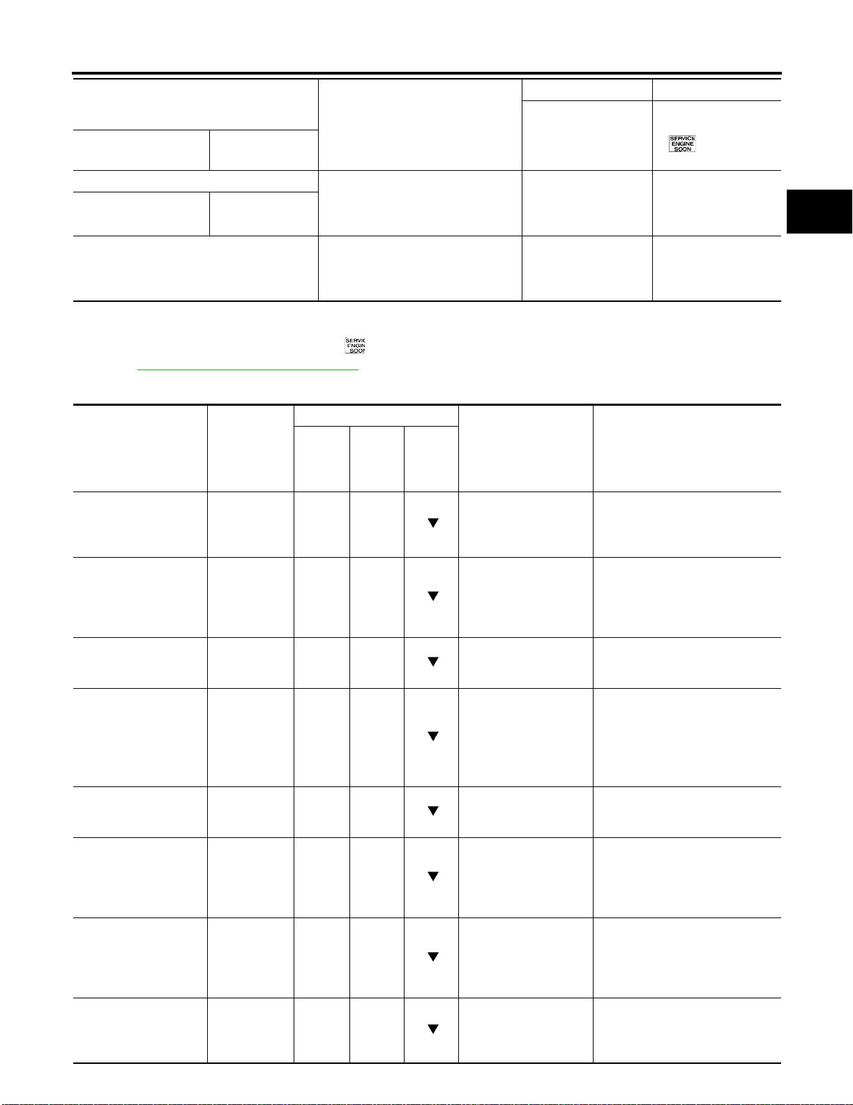
ON BOARD DIAGNOSTIC SYSTEM DESCRIPTION
[RE4F04B]
Detected items
(Screen terms for CONSULT-II, “SELF
DIAGNOSIS” test mode)
“A/T”“ENGINE”
Initial start ● This is not a malfunction message
INITIAL START —
No failure
(NO SELF DIAGNOSTIC FAILURE INDICATED FURTHER TESTING MAY BE
REQUIRED**)
X: Applicable
−: Not applicable
*1: These malfunctions cannot be display ed by M IL if another malfun ct ion is as sig ned t o MIL.
*2: Refer to EC-66, "Malfunction Indicator Lamp (MIL)" .
Malfunction is detected when...
(Whenever shutting off a power
supply to the TCM, this message
appears on the screen.)
● No failure has been detected. X X
TCM self-diagnosis OBD-II (DTC)
Available by A/T check
(position) indicator
lamp or “A/T” on
CONSULT-II
DATA MONITOR MODE (A/T)
Monitor item
Item Display
Vehicle speed sensor 1
(A/T)
(Revolution sensor)
Vehicle speed sensor 2
(Meter)
Throttle position sensor
[accelerator pedal position (APP) sensor]
A/T fluid temperature
sensor
Battery voltage BATTERY
Engine speed ENGINE
Turbine revolution sensor
Overdrive control
switch
VHCL/S
SE·A/T
[km/h] or
[mph]
VHCL/S
SE·MTR
[km/h] or
[mph]
THRTL POS
SEN [V]
FLUID TEMP
SE
[V]
VOLT
[V]
SPEED
[rpm] X X
TURBINE
REV
OVERDRIVE
SW
[ON/OFF]
TCM
Input
signals
X —
X —
X —
X —
X —
X —
X —
Main
signals
Selec-
tion
from
menu
Description Remarks
● Vehicle speed com-
puted from signal of
revolution sensor is
displayed.
● Vehicle speed com-
puted from signal of
vehicle speed sensor
is displayed.
● Throttle position sen-
sor signal voltage is
displayed
● A/T fluid temperature
sensor signal voltage
is displayed.
● Signal voltage lowers
as fluid temperature
rises.
● Source voltage of
TCM is dis played.
● Engine speed, com-
puted from engine
speed signal, is displayed.
● Checks changing
speed then performs
oil pressure control
and torque down
control
● ON/OFF state com-
puted from signal of
3 position switch is
displayed.
Available by malfunction indicator lamp*2,
“ENGINE” on
CONSULT-II or GST
X —
● When racing engine in N or P
with vehicle stationary, CONSULT -II data may not indicate 0
km/h (0 mph).
● Vehicle speed display may not
be accurate under approx. 10
km/h (6 mph). It may not indicate 0 km/h (0 mph) when vehicle is stationary.
● Engine speed display may not
be accurate under approx. 800
rpm. It may not indicate 0 rpm
even when engine is not running.
A
B
AT
D
E
F
G
H
I
J
K
L
M
Revision: July 2005 2006 Altima
AT-51
Page 74
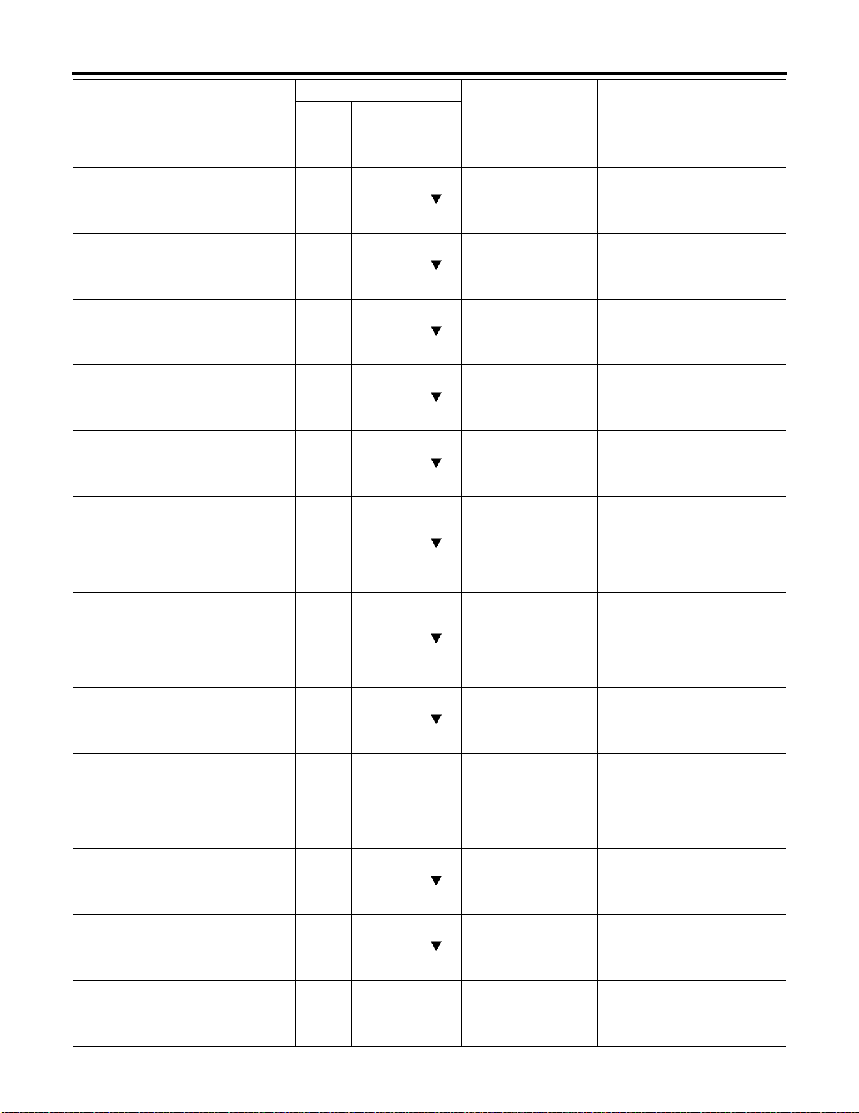
ON BOARD DIAGNOSTIC SYSTEM DESCRIPTION
Item Display
PN position (PNP)
switch
R position switch R POSITI ON
D position switch D POSITI ON
2 position switch 2 POSITION
1 position switch 1 POSITION
ASCD cruise signal ASCD·CRUIS
ASCD OD cut signal ASCD·OD
Kickdown switch KICKDOWN
Stop lamp switch BRAKE SW
Selector lever position SLCT LVR
Vehicle speed VEHICLE
Throttle position
[Accelerator pedal
position (APP) sensor]
PN POSI SW
[ON/OFF]
SW
[ON/OFF]
SW
[ON/OFF]
SW
[ON/OFF]
SW
[ON/OFF]
E
[ON/OFF]
CUT
[ON/OFF]
SW
[ON/OFF]
[ON/OFF]
POSI
SPEED
[km/h] or
[mph]
THROTTLE
POSI
[/8]
Monitor item
TCM
Input
signals
Main
signals
Selec-
tion
from
menu
X —
X —
X —
X —
X —
X —
X —
X —
X ——
— X
— X
— X —
Description Remarks
● ON/OFF state com-
puted from signal of
PN position SW is
displayed.
● ON/OFF state com-
puted from signal of
R position SW is displayed.
● ON/OFF state com-
puted from signal of
D position SW is displayed.
● ON/OFF status,
computed from signal of 2 position SW,
is displayed.
● ON/OFF status,
computed from signal of 1 position SW,
is displayed.
● Status of ASCD
cruise signal is displayed.
ON ... Cruising state
OFF ... Normal running state
● Status of ASCD OD
release signal is displayed.
ON ... OD released
OFF ... OD not
released
● ON/OFF status,
computed from sig-
● This is displayed even when no
kickdown switch is equipped.
nal of kickdown SW,
is displayed.
● ON/OFF status is
displayed.
ON ... Brake pedal is
depressed.
OFF ... Brake pedal
is released.
● Selector lever posi-
tion data, used for
computation by
● A specific value used for con-
trol is displayed if fail-safe is
activated due to error.
TCM, is displayed.
● Vehicle speed data,
used for computation by TCM, is displayed.
● Throttle position
data, used for computation by TCM, is
● A specific value used for con-
trol is displayed if fail-safe is
activated due to error.
displayed.
[RE4F04B]
Revision: July 2005 2006 Altima
AT-52
Page 75
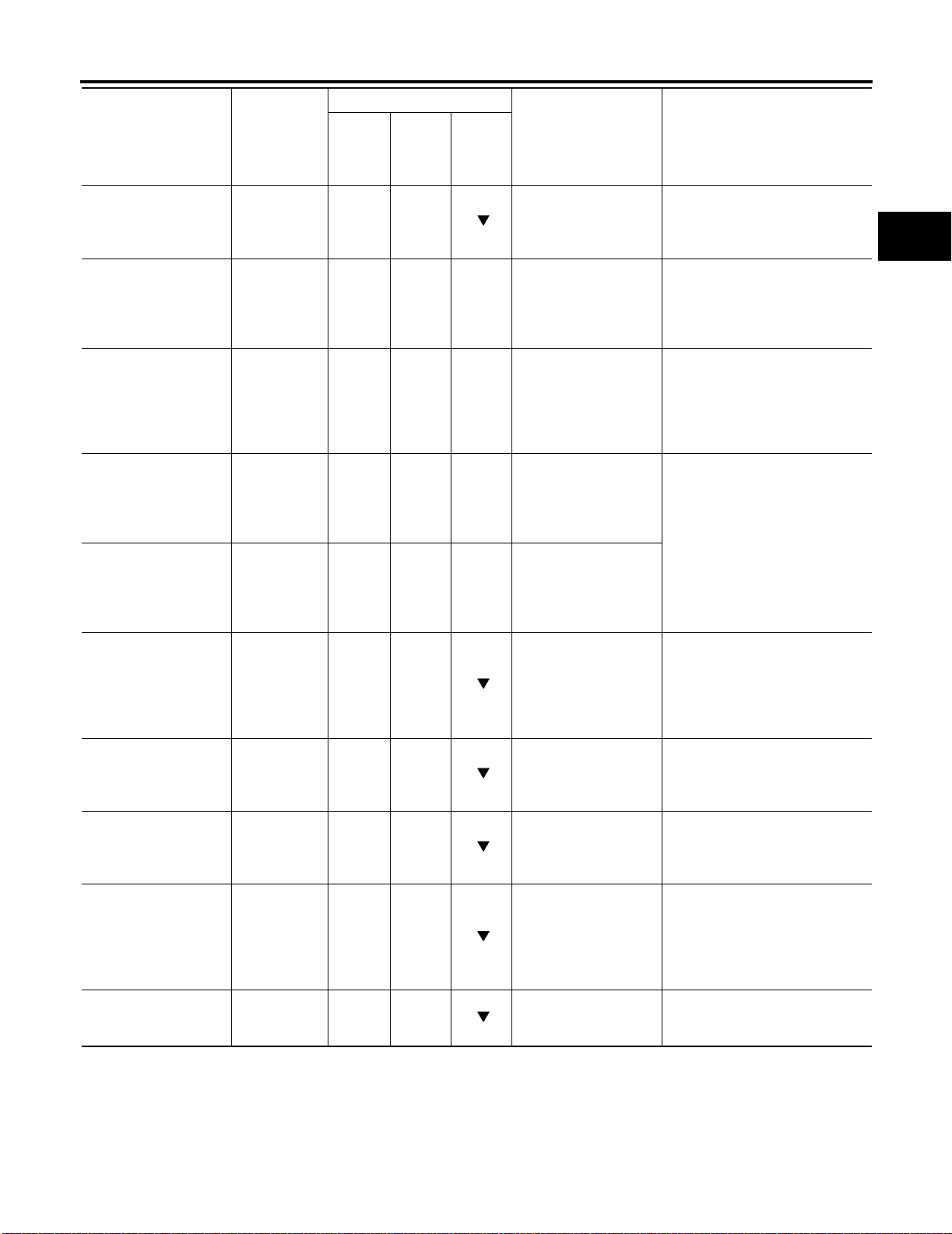
ON BOARD DIAGNOSTIC SYSTEM DESCRIPTION
[RE4F04B]
Monitor item
Item Display
Gear position GEAR
Line pressure duty LINE PRE S
DTY
[%] — X —
T orque converter clutch
solenoid valve duty
Shift solenoid valve A SHIFT S/V A
Shift solenoid valve B SHIFT S/V B
Overrun clutch solenoid valve
Self-diagnosis display
lamp [A/T check (position) indicator lamp]
Torque converter slip
ratio
Torque converter slip
speed
Voltage [V] ——
TCC S/V
DUTY
[%]
[ON/OFF]
[ON/OFF]
OVERRUN/C
S/V
[ON/OFF]
SELF-D DP
LMP
[ON/OFF]
TC SLIP
RATIO [0.000]
TC SLIP
SPEED [rpm]
TCM
Input
signals
— X
— X —
— X —
— X —
— X
— X
——
——
Main
signals
Selec-
tion
from
menu
Description Remarks
● Gear position data
used for computation by TCM, is displayed.
● Control value of line
pressure solenoid
valve, computed by
TCM from each input
signal, is displayed.
● Control value of
torque converter
clutch solenoid
valve, computed by
TCM from each input
signal, is displayed.
● Control value of shift
solenoid valve A,
computed by TCM
from each input signal, is displayed.
● Control value of shift
solenoid valve B,
computed by TCM
from each input signal, is displayed.
● Control value of
overrun clutch solenoid valve computed
by TCM from each
input signal is displayed.
● Control status of A/T
check (position) indicator lamp is displayed.
● Ratio of engine revo-
lution to input shaft
revolution of torque
converter.
● Difference in revolu-
tion between input
shaft revolution and
torque converter
input shaft revolution.
● Value measured by
voltage probe is displayed.
● Control value of solenoid is dis-
played even if solenoid circuit
is disconnected.
The OFF signal is displayed if
solenoid circuit is shorted.
● Display does not indicate
engine is stopped even if 0 rpm
— this is not a malfunction.
A
B
AT
D
E
F
G
H
I
J
K
L
M
Revision: July 2005 2006 Altima
AT-53
Page 76
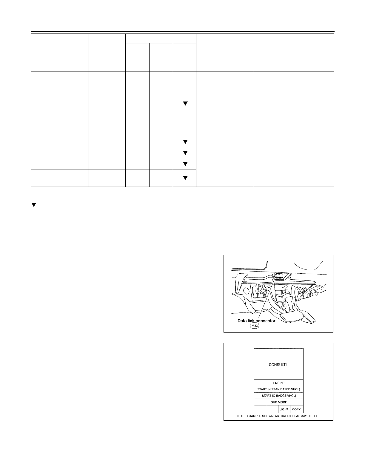
ON BOARD DIAGNOSTIC SYSTEM DESCRIPTION
Monitor item
Item Display
Frequency [Hz] ——
DUTY-HI ——
DUTY-LOW ——
PLS WIDTH-HI ——
PLS WIDTH-LOW ——
X: Applicable
—: Not applicable
: Option
TCM
Input
signals
Main
signals
Selec-
tion
from
menu
[RE4F04B]
Description Remarks
● Value measured by
pulse probe is displayed. If measurement is impossible,
"#" sign is displayed.
"#" sign is also displayed at the final
data value until the
measurement result
is obtained.
● Duty cycle value for
measurement probe
is displayed.
● Measured pulse
width of measurement probe is displayed.
DTC WORK SUPPORT MODE WITH CONSULT-II
CONSULT-II Setting Procedure
CAUTION:
If CONSULT-II is used with no connection of CONSULT-II CONVERTER, malfunctions might be
detected in self-diagnosis depending on control unit which carry out CAN communication.
1. Turn ignition switch OFF.
2. Connect CONSULT-II and CONSULT-II CONVERTER to data
link connector, which is located in left side dash panel.
LCIA0042E
3. Turn ignition switch ON. (Do not start engine)
4. Touch “ST ART (NISSAN BASED VHCL)”.
BCIA0029E
Revision: July 2005 2006 Altima
AT-54
Page 77
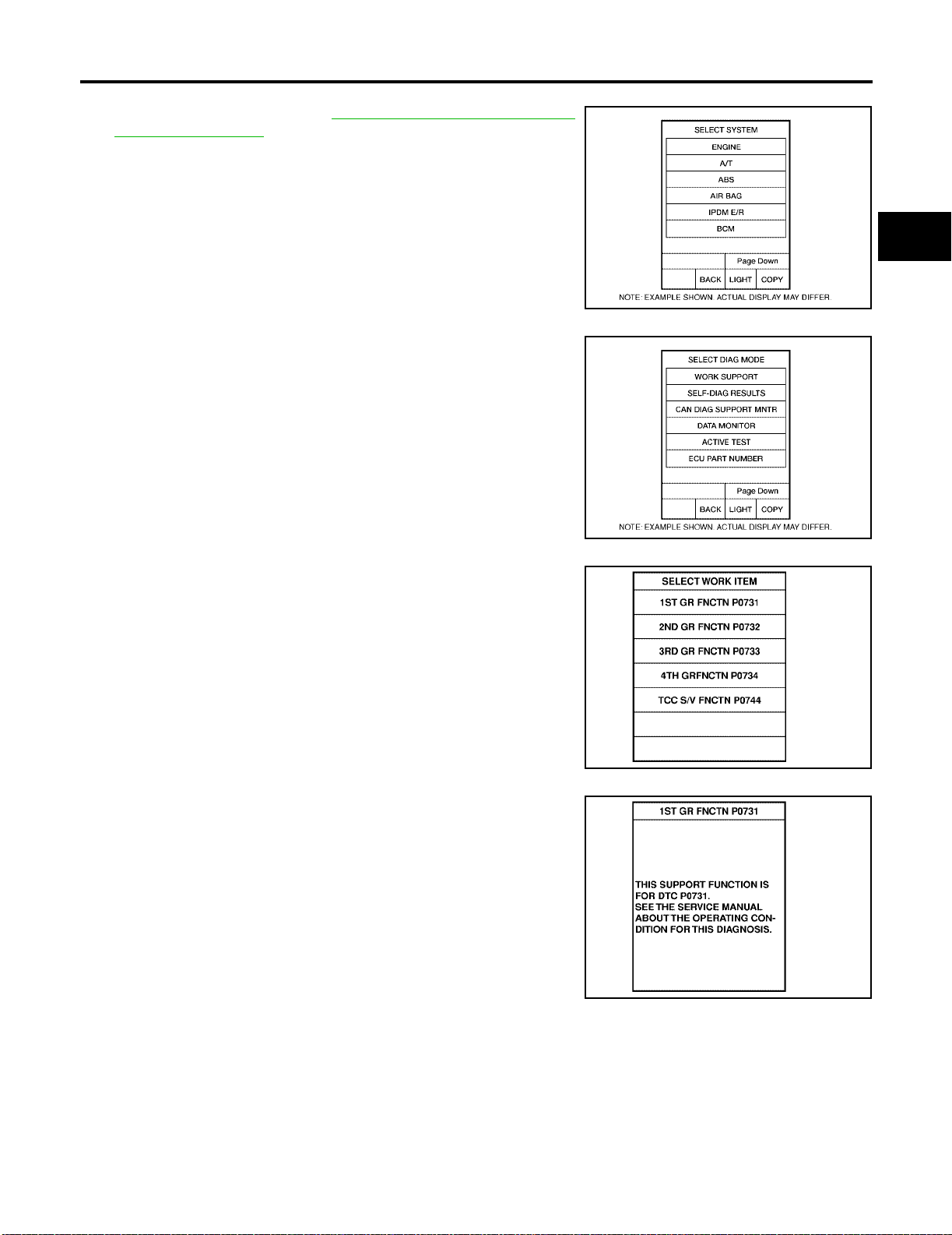
ON BOARD DIAGNOSTIC SYSTEM DESCRIPTION
5. Touch “A/T”.
If "AT" is not indicated, go to GI-39, "
nector (DLC) Ci rcuit" .
Consult-II Data Link Con-
[RE4F04B]
A
B
AT
6. Touch “DTC WORK SUPPORT”.
7. Touch select item menu (1ST, 2ND, etc.).
BCIA0030E
BCIA0031E
D
E
F
G
H
I
J
K
SAT018K
8. Touch “START”.
SAT589J
Revision: July 2005 2006 Altima
AT-55
L
M
Page 78
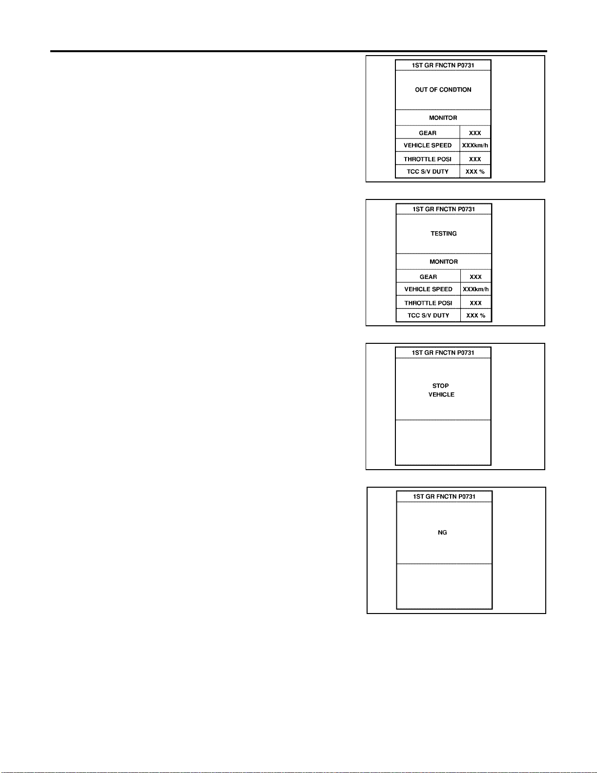
ON BOARD DIAGNOSTIC SYSTEM DESCRIPTION
9. Perform driving test according to “DTC CONFIRMATION PROCEDURE” in “TROUBLE DIAGNOSIS FOR DTC”.
● When testing conditions are satisfied, CONSULT-II screen
changes from “OUT OF CONDITION” to “TESTING”.
[RE4F04B]
SAT019K
10. Stop vehicle. If “NG” appears on the screen, malfunction may
exist. Go to “DIAGNOSTIC PROCEDURE”.
SAT591J
SAT592J
SAT593J
Revision: July 2005 2006 Altima
AT-56
Page 79
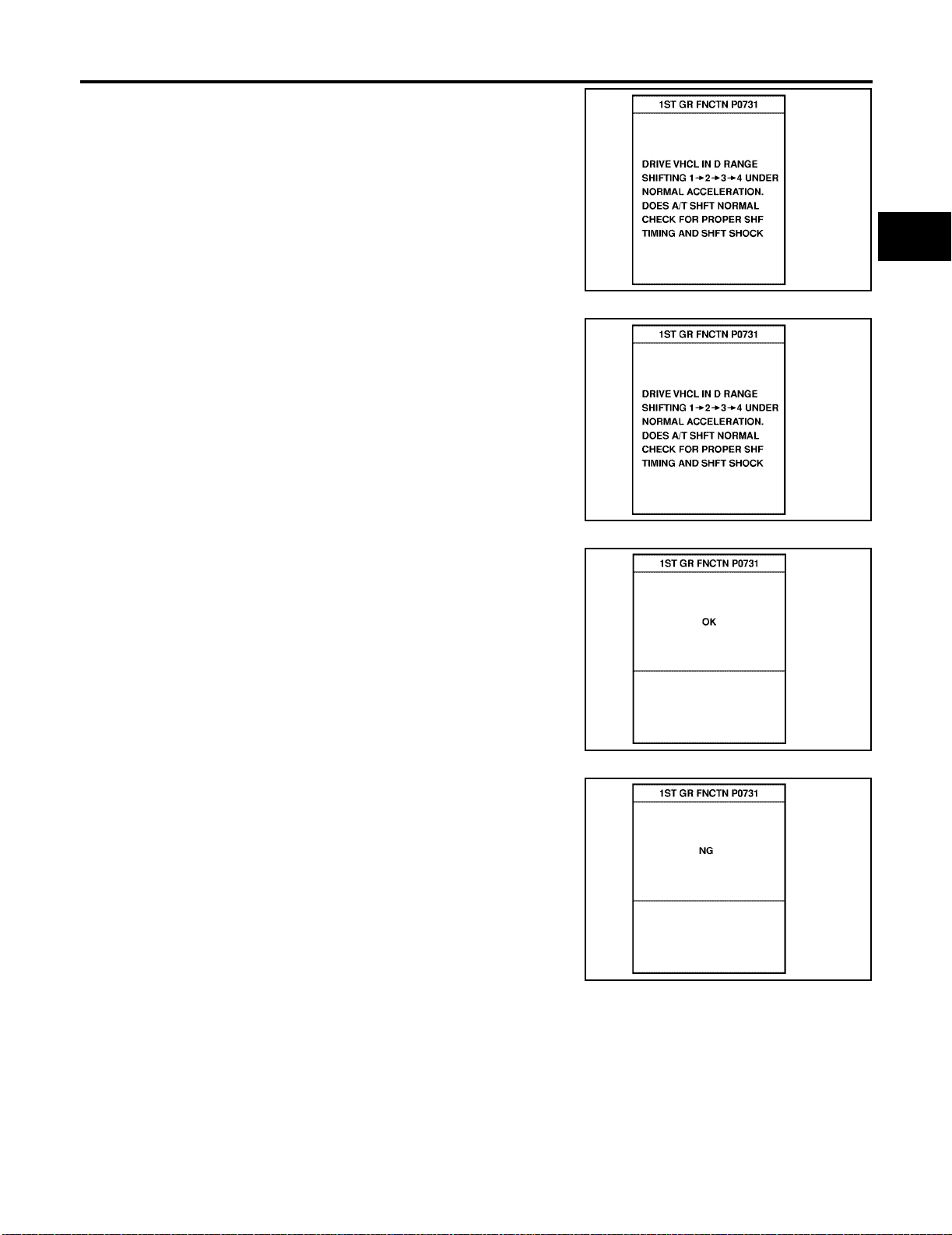
ON BOARD DIAGNOSTIC SYSTEM DESCRIPTION
11. P erform test driv e to c hec k ge ar sh ift feel ing i n ac corda nce w ith
instructions displayed.
12. Touch “YES” or “NO”.
[RE4F04B]
A
B
AT
SAT594J
D
E
F
G
SAT595J
13. CONSULT-II procedure ended.
If “NG” appears on the screen, a malfunction may exist. Go to “DIAGNOSTIC PROCEDURE”.
SAT596J
SAT593J
H
I
J
K
L
M
DTC WORK SUPPORT MODE
Revision: July 2005 2006 Altima
AT-57
Page 80

ON BOARD DIAGNOSTIC SYSTEM DESCRIPTION
DTC work support item Description Check item
1ST GR FNCTN P0731
2ND GR FNCTN P0732
3RD GR FNCTN P0733
4TH GR FNCTN P0734
TCC S/V FNCTN P0744
Following items for “A/T 1st gear function (P0731)” can be confirmed.
● Self-diagnosis status (whether the diagnosis is being conducted
or not)
● Self-diagnosis result (OK or NG)
Following items for “A/T 2nd gear function (P0732)” can be confirmed.
● Self-diagnosis status (whether the diagnosis is being conducted
or not)
● Self-diagnosis result (OK or NG)
Following items for “A/T 3rd gear function (P0733)” can be confirmed.
● Self-diagnosis status (whether the diagnosis is being conducted
or not)
● Self-diagnosis result (OK or NG)
Following items for “A/T 4th gear function (P0734)” can be confirmed.
● Self-diagnosis status (whether the diagnosis is being conducted
or not)
● Self-diagnosis result (OK or NG)
Following items for “A/T TCC S/V function (lock-up) (P0744)” can
be confirmed.
● Self-diagnosis status (whether the diagnosis is being conducted
or not)
● Self-diagnosis result (OK or NG)
● Shift solenoid valve A
● Shift solenoid valve B
● Each clutch
● Hydraulic control circuit
● Shift solenoid valve B
● Each clutch
● Hydraulic control circuit
● Shift solenoid valve A
● Each clutch
● Hydraulic control circuit
● Shift solenoid valve A
● Shift solenoid valve B
● Overrun clutch sol enoi d val ve
● Line pressure solenoid val ve
● Each clutch
● Hydraulic control circuit
● T orque converter clutch sole-
noid valve
● Each clutch
● Hydraulic control circuit
[RE4F04B]
Revision: July 2005 2006 Altima
AT-58
Page 81
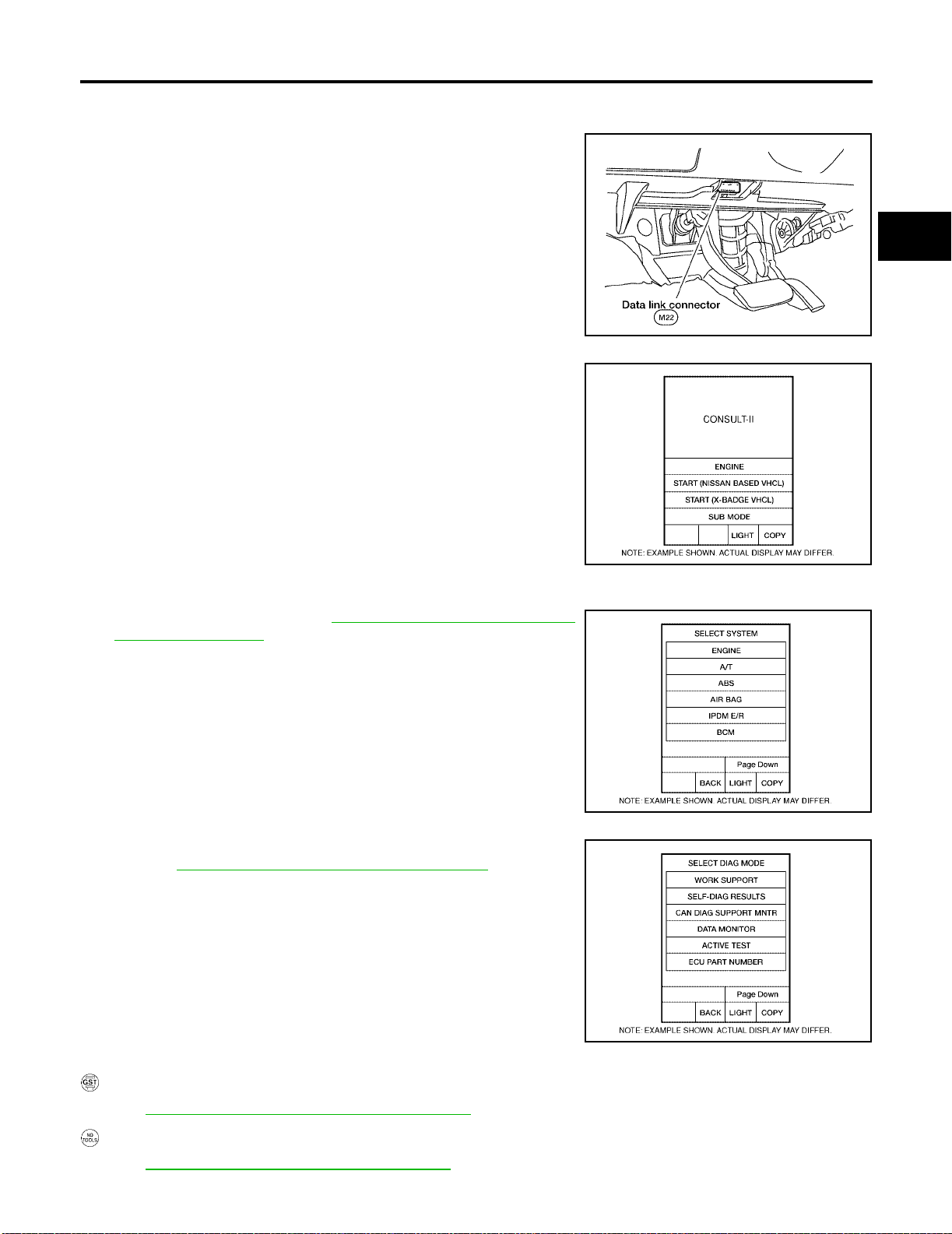
ON BOARD DIAGNOSTIC SYSTEM DESCRIPTION
CAN DIAGNOSTIC SUPPORT MONITOR
CONSULT-II Setting Procedure
1. Turn ignition switch OFF.
2. Connect CONSULT-II and CONSULT II CONVERTER to data
link connector, which is located in left side dash panel.
[RE4F04B]
A
B
AT
D
LCIA0042E
3. Turn ignition switch ON. (Do not start engine.)
4. Touch “START (NISSAN BASED VHCL)”.
5. Touch “A/T”.
If "AT" is not indicated, go to GI-39, "
Consult-II Data Link Con-
nector (DLC) Ci rcuit" .
BCIA0029E
BCIA0030E
E
F
G
H
I
J
K
L
6. Touch “CAN DIAGNOSTIC SUPPORT MONITOR”.
Refer to LAN-15, "
Diagnostic Procedure Without CONSULT-II
CAN Diagnostic Support Monitor" .
BCIA0031E
ECS00965
OBD-II SELF-DIAGNOSTIC PROCEDURE (WITH GST)
Refer to EC-129, "Generic Scan Tool (GST) Function" .
OBD-II SELF-DIAGNOSTIC PROCEDURE (NO TOOLS)
Refer to EC-66, "Malfunction Indicator Lamp (MIL)" .
Revision: July 2005 2006 Altima
AT-59
M
Page 82
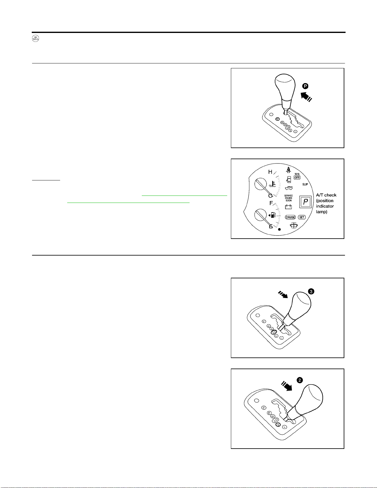
ON BOARD DIAGNOSTIC SYSTEM DESCRIPTION
TCM SELF-DIAGNOSTIC PROCEDURE (NO TOOLS)
1. CHECK A/T CHECK (POSITION) INDICATOR LAMP
1. Move selector lever to P position.
Start engine and warm it up to norm al e ngine opera ting temp erature.
2. Turn ignition switch to OFF position.
3. Wait 5 seconds.
4. Turn ignition switch to ON position.
(Do not start engine.)
5. Does A/T check (po sition) indicator lamp come on for about 2
seconds?
Yes or No
Yes >> GO TO 2.
No >> Stop procedure. Perform AT- 2 17 , "
tion) Indicator La mp Does Not Come On" before pro-
ceeding.
1. A/T Check (Posi-
[RE4F04B]
LCIA0043E
2. JUDGEMENT PROCEDURE STEP 1
1. Turn ignition switch to OFF position.
2. Push and hold shift lock button.
3. Depress the brake pedal, then move gear selector lever from P
to 3 position.
4. Wait 3 seconds.
5. Move selector l ever to 2 position.
6. Release brake pedal.
>> GO TO 3.
WCIA0458E
WCIA0344E
LCIA0046E
Revision: July 2005 2006 Altima
AT-60
Page 83
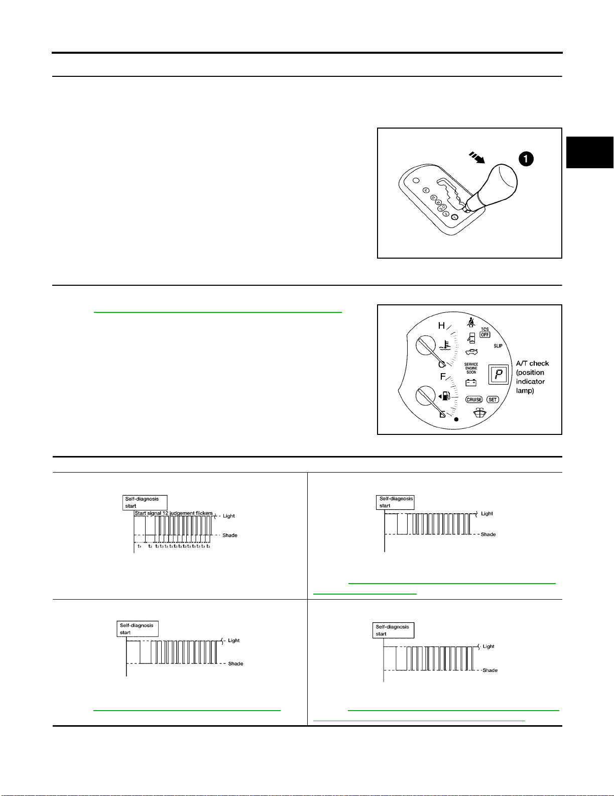
ON BOARD DIAGNOSTIC SYSTEM DESCRIPTION
[RE4F04B]
3. JUDGEMENT PROCEDURE STEP 2
1. Move selector lever to 1 position.
2. Depress brake pedal.
3. Depress accelerator pedal fully and release it.
4. The A/T check (position) indicator lamp will begin to flash.
>> GO TO 4.
4. CHECK SELF-DIAGNOSTIC CODE
Check A/T check (po si t io n) indicator lamp.
Refer to AT-61, "
>> DIAGNOSIS END
JUDGEMENT OF SELF-DIAGNOSIS CODE" .
A
B
AT
D
E
LCIA0047E
F
G
H
JUDGEMENT OF SELF-DIAGNOSIS CODE
A/T check (position) indicator lamp:
All judgement flickers are the same.
LCIA0049E LCIA0050E
All circuits that can be confirmed by self-diagnosis are OK.
2nd judgement flicker is longer than others.
1st judgement flicker is longer than others.
Revolution sensor circuit is short-ci rcu ited or disc onnected.
Þ Go to AT-122, "
(REVOLUTION SENSOR)" .
3rd judgement flicker is longer than others.
DTC P0720 VEHICLE SPEED SENSOR·A/T
WCIA0458E
I
J
K
L
M
LCIA0051E LCIA0052E
Vehicle speed sensor circuit is short-circuited or disconnected.
Þ Go to A T-201, "
DTC VEHICLE SPEED SENSOR MTR" .
Revision: July 2005 2006 Altima
Throttle position sensor circuit is short-circui t ed or disconnected.
Þ Go to AT-182, "DTC P1705 THROTTLE POSITION SENSOR
[ACCELERATOR PEDAL POSITION (APP) SENSOR]".
AT-61
Page 84
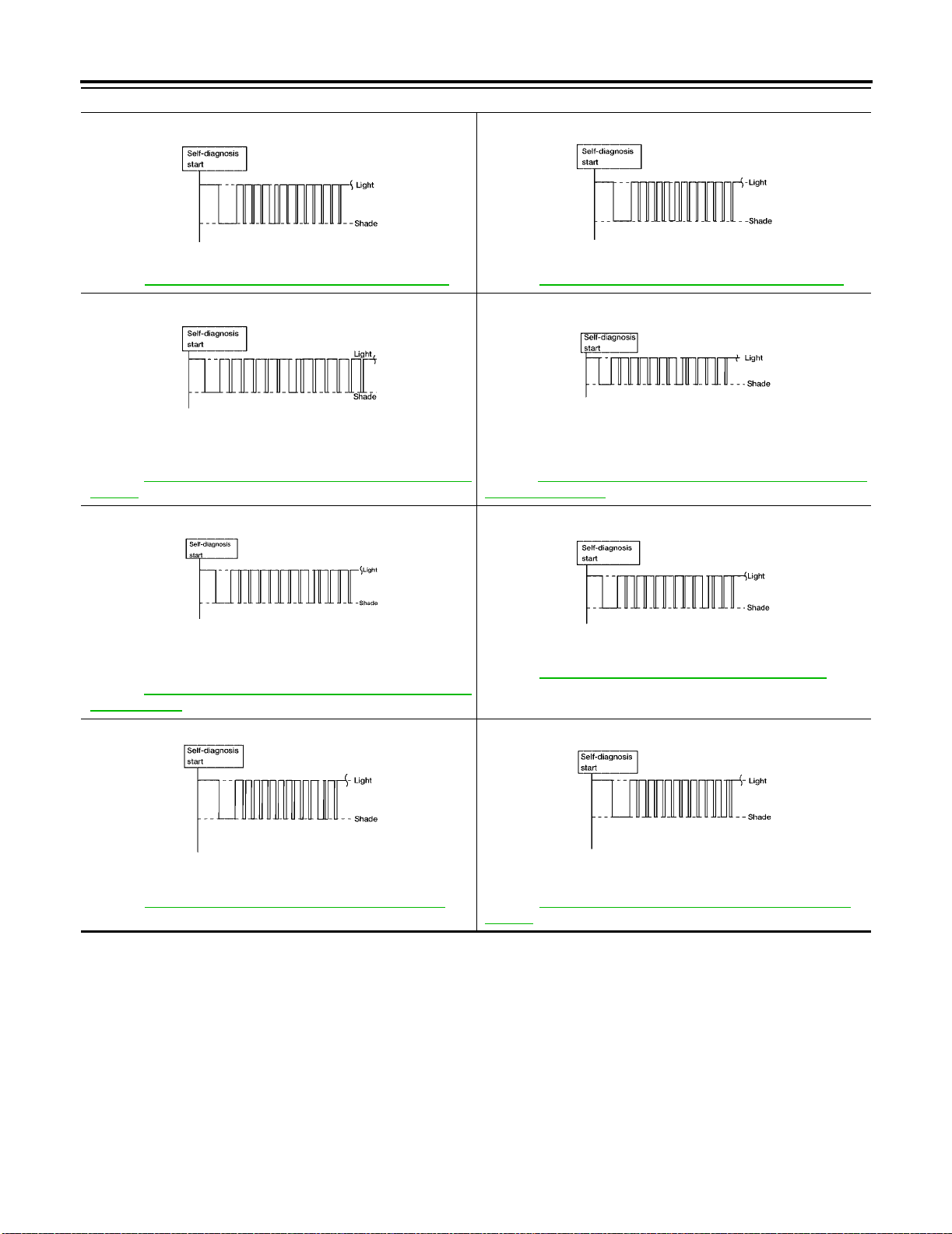
ON BOARD DIAGNOSTIC SYSTEM DESCRIPTION
A/T check (position) indicator lamp:
4th judgement flicker is longer than others.
LCIA0053E LCIA0054E
Shift solenoid valve A circuit is short-circuited or disconnected.
Þ Go to AT-172, "
6th judgement flicker is longer than others.
Overrun clutch solenoid valve circu it is short- ci rcu ited or disc onnected.
Þ Go to AT-185, "
VALVE" .
8th judgement flicker is longer than others.
DTC P0750 SHIFT SOLENOID VALVE A" .
LCIA0055E LCIA0056E
DTC P1760 OVERRUN CLUTCH SOLENOID
[RE4F04B]
5th judgement flicker is longer than others.
Shift solenoid valve B circuit is short-circuited or disco nnected.
Þ Go to AT-177, "
7th judgement flicker is longer than others.
Tor que converter clutch solenoid valve circ uit is shor t-ci rcu ited or
disconnected.
Þ Go to AT -153, "
SOLENOID VALVE" .
9th judgement flicker is longer than others.
DTC P0755 SHIFT SOLENOID VALVE B" .
DTC P0740 TORQUE CONVERTER CLUTCH
LCIA0057E LCIA0058E
A/T fluid temperature sensor is disconnec te d or TCM pow er
source circuit is damaged.
Þ Go to AT-116, "
SOR CIRCUIT" .
10th judgement flicker is longer than other s.
Turbine revolution sensor circuit is short-circuited or disconnected.
Þ Go to AT-205, "
DTC P0710 A/T FLUID TEMPERATURE SEN-
LCIA0059E LCIA0060E
DTC TURBINE REVOLUTION SENSOR" .
Engine speed signal circuit is short-circuited or disconnected.
Þ Go to AT-127, "DTC P0725 ENGINE SPEED SIGNAL" .
11th judgement flicker is longer than others.
Line pressure solenoid valve circuit is shor t-ci rcu ited or dis connected.
Þ Go to AT-166, "DTC P0745 LINE PRESSURE SOLENOID
VALVE" .
Revision: July 2005 2006 Altima
AT-62
Page 85
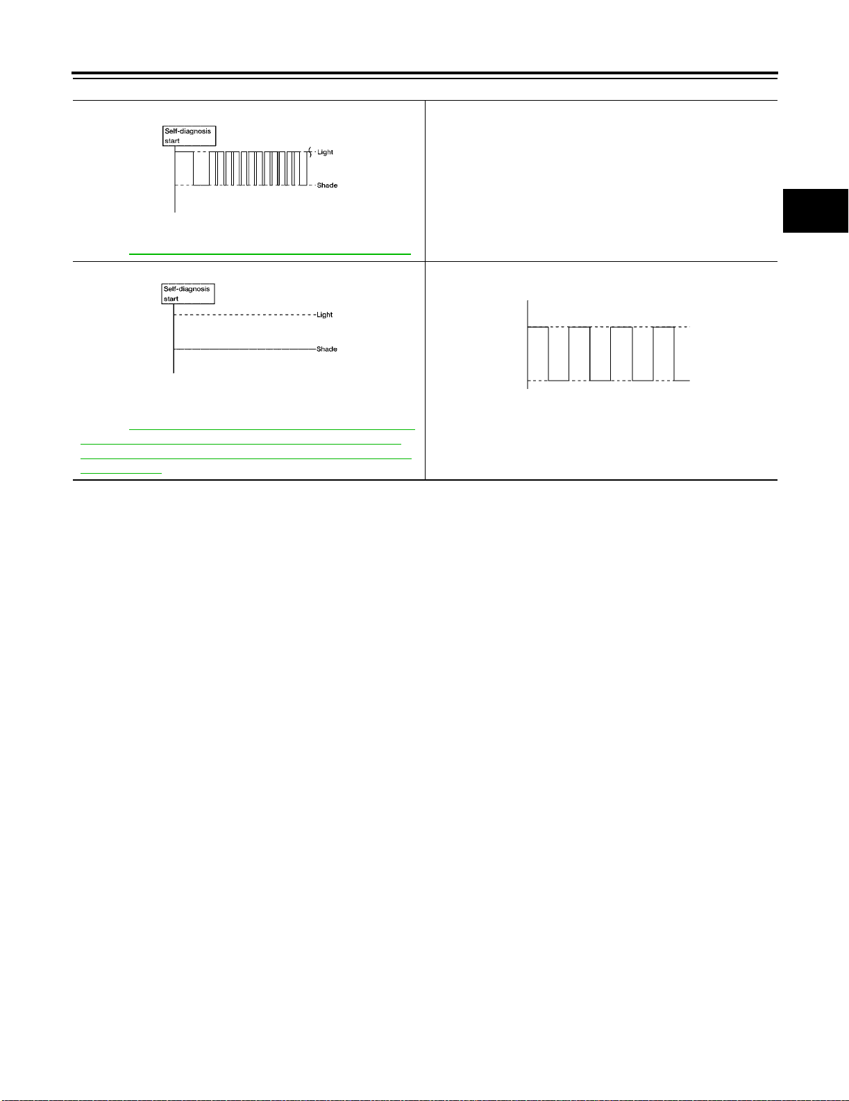
ON BOARD DIAGNOSTIC SYSTEM DESCRIPTION
[RE4F04B]
A/T check (position) indicator lamp:
12th judgement flicker is longer than others.
LCIA0061E
The ECM-A/T communication line is open or shorted.
Þ Go to A T-190, "
Lamp turns off.
Park/neutral position (PNP) switch, and 3 position switch circuit is
disconnected or TCM is damaged.
Þ Go to A T-254, "
(PNP & 3 Position Switches Circui t Checks) , and Thr ottle
Position Sensor [Accelerator Pedal Position (APP) Sensor]
Circuit Check" .
t1 = 2.5 seconds t2 = 2.0 seconds t3 = 1.0 second t4 = 1.0 second
DTC U1000 CAN COMMUNICATION LINE" .
LCIA0062E LCIA0063E
21. TCM Self-diagnosis Does Not Activate
Flickers as shown below.
Battery power is low.
Battery has been disconnected for a long time.
Battery is connected conversely.
(When reconnecting TCM connect or s. — Thi s is not a pro blem .)
A
B
AT
D
E
F
G
H
K
M
I
J
L
Revision: July 2005 2006 Altima
AT-63
Page 86
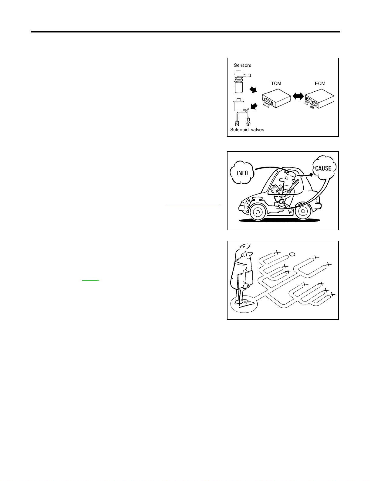
TROUBLE DIAGNOSIS - INTRODUCTION
[RE4F04B]
TROUBLE DIAGNOSIS - INTRODUCTION PFP:00000
Introduction
The TCM receives a signal from the vehicle speed sensor, ECM
(throttle opening) or park/neutral position (PNP) switch and provides
shift control or lock- up cont rol via A/T so le no id valv es .
The TCM also communicates with the ECM by means of a signal
sent from sensing elements used with the OBD-related parts of the
A/T system for malfu nction-diagnostic purpo ses. The TCM is capable of diagno si ng malfunction in g parts wh ile th e ECM can store malfunctions in its memory.
Input and output signals must always be correct and stable in the
operation of the A/T system. The A/T system must be in good operating condition and be free of valve seizure, solenoid valve malfunction, etc.
It is much more difficult to diagn ose a problem th at occurs intermi ttently rather than continuously. Most intermittent problems are
caused by po or electric connections or improp er wiring. In this ca se,
careful checking of suspected circuits may help prevent the replacement of good parts.
A visual check only, may not find the cause of the problems. A road
test with CONSULT-II (or GST) or a circuit tester connec ted should
be performed. Follow the “Work Flow”. Refer to AT-68, "
Work Flow" .
ECS00966
SAT631IA
Before undertaking a ctual checks, take a fe w minutes to talk with a
customer who approaches with a driveability complaint. The customer can supply good information about such problems, especially
intermittent ones. Find out what symptoms are present and under
what conditions they occur. A “DIAGNOSTIC WORKSHEET” like the
example on page AT-66
should be used.
Start your diagnosis by looking for “conventional” problems fir s t. Th is
will help troubleshoot driveability problems on an electronically controlled engine vehicle.
Also check related Service bulletins for information.
SAT632I
SEF234G
Revision: July 2005 2006 Altima
AT-64
Page 87
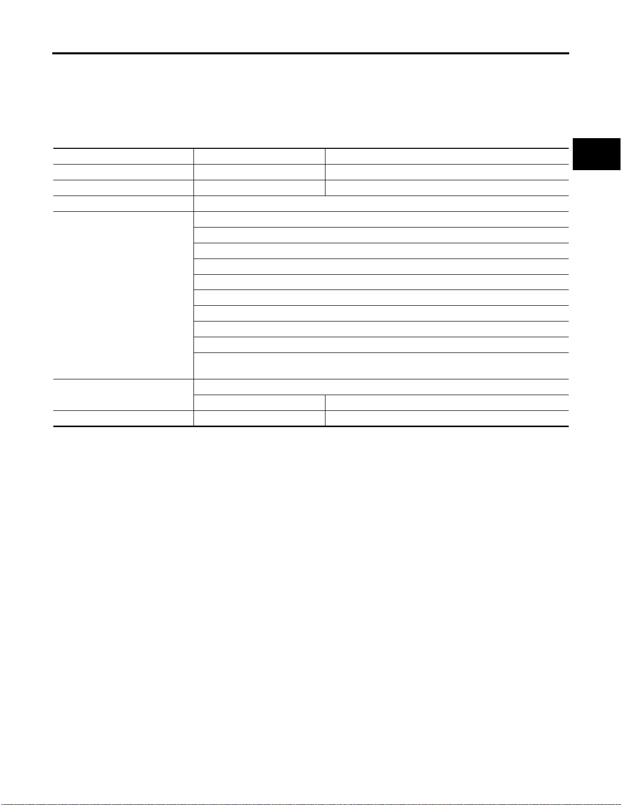
TROUBLE DIAGNOSIS - INTRODUCTION
DIAGNOSTIC WORKSHEET
Information from Customer
KEY POINTS
WHAT ........ Vehicle & A/T model
WHEN ........ Date, Frequencies
WHERE ..... Road conditions
HOW .......... Operating cond iti on s, Symp to ms
Customer name MR/MS Model & Year VIN
Trans. model Engine Mileag e
Incident Date Manuf. Date In Service Date
Frequency ❏ Continuous ❏ Intermittent ( times a day)
Symptoms ❏ Vehicle does not move. (❏ Any position ❏ Particular position)
❏ No up-shift (❏ 1st → 2nd ❏ 2nd → 3rd ❏ 3rd → 4th)
❏ No down-shift (❏ 4th → 3rd ❏ 3rd → 2nd ❏ 2nd → 1st)
❏ Lockup malfunction
❏ Shift point too high or too low.
❏ Shift shock or slip (❏ N → D ❏ Lockup ❏ Any drive position)
❏ Noise or vibration
❏ No kickdown
❏ No pattern select
❏ Others
()
A/T check (position) indicator lamp Blinks for about 8 seconds .
❏ Continuously lit ❏ Not lit
Malfunction indic ator lamp (MIL) ❏ Continuously lit ❏ Not lit
[RE4F04B]
A
B
AT
D
E
F
G
H
I
K
M
J
L
Revision: July 2005 2006 Altima
AT-65
Page 88
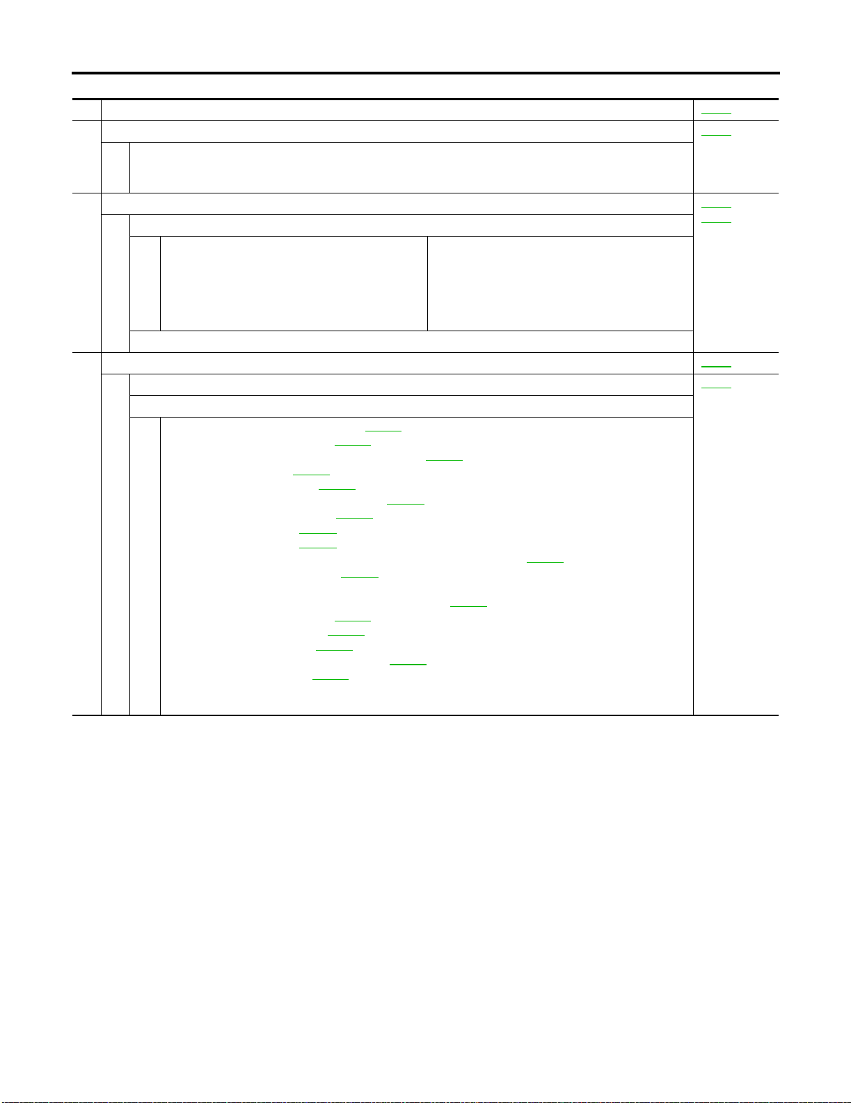
TROUBLE DIAGNOSIS - INTRODUCTION
[RE4F04B]
Diagnostic Worksheet
1. ❏ Read the Fai l-saf e and lis te n to cus tomer complaints. AT-12
2. ❏ CHECK A/T FLUID AT-71
❏ Leakage (Follow specified procedure )
❏ Fluid condition
❏ Fluid level
3. ❏ Perform STALL TEST and PRESSURE TEST. AT-74
❏ Stall test — Mark possible damaged components/others .
❏ Torque converter one-way clutch
❏ Reverse clutch
❏ Forward clutch
❏ Overrun clutch
❏ Forward one-way clutch
❏ Pressure test — Suspected parts:
4. ❏ Perform all ROAD TEST and mark req uired pr oce dur es. AT-78
4-1.Check before engine is started. AT-80
❏ SELF-DIAGNOSTIC PROCEDURE - Mark detected items.
❏ Park/neutral position (PNP) switch, AT-110
❏ A/T fluid temperature sensor, AT-116 .
❏ Vehicle speed sensor·A/T (Revolution sensor), AT-122
❏ Engine speed signal, AT-127
❏ Turbine revolution sensor, AT-205
❏ Torque converter clutch solenoid valve, AT-153
❏ Line pressure solenoid valve, AT-166
❏ Shift solenoid valve A, AT-172
❏ Shift solenoid valve B, AT-177
❏ Throttle position sensor [accelerator pedal pos ition (APP) sensor], AT-182
❏ Overrun clutch solenoid valve, AT-185
❏ Park/neutral position (PNP) & 3 position switche s circu it check s, and th rottle pos iti on sensor
[accelerator pedal position (APP) sensor circuit check AT-254 .
❏ A/T fluid temperature sensor, AT-116
❏ Vehicle speed sensor·MTR, AT-201
❏ CAN communication line, AT-190
❏ Control unit (RAM), Control unit (ROM), AT-209
❏ Control unit (EEP ROM), AT-211
❏ Battery
❏ Others
.
.
.
.
.
.
.
.
.
.
❏ Low & reverse brake
❏ Low one-way clutch
❏ Engine
❏ Line pressure is low
❏ Clutches and brakes except high clutch and
brake band are OK
.
.
.
.
AT-77
,
Revision: July 2005 2006 Altima
AT-66
Page 89
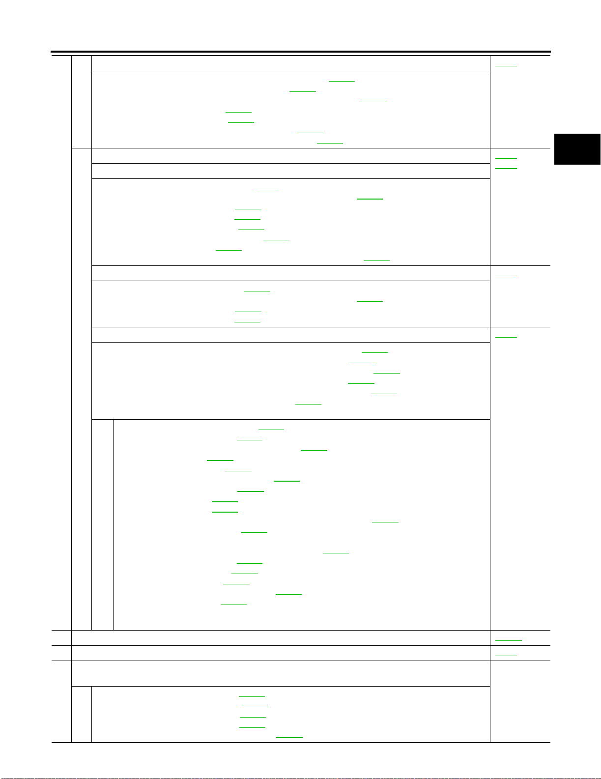
TROUBLE DIAGNOSIS - INTRODUCTION
[RE4F04B]
4-2.Check at idle AT-80
❏ 1. A/T Check (Position) Indicator Lamp Does Not Come On, AT-217 .
❏ 2. Engine Cannot Be Started In P and N Position, AT-219
❏ 3. In P Position, Vehicle Moves Forward or Backward When Pushed, AT-220
❏ 4. In N Position, Vehicle Moves, AT-221
❏ 5. Large Shock. N → R Position, AT-223
❏ 6. Vehicle Does Not Creep Backward In R Position, AT-225
❏ 7. Vehicle Does Not Creep Forward In D, 2 or 1 Position, AT-228
4-3.Cruise test AT-82
Part-1
❏ 8. Vehicle Cannot Be Started From D
❏ 9. A/T Does Not Shift: D
❏ 10. A/T Does Not Shift: D
❏ 11. A/T Does Not Shift: D
❏ 12. A/T Does Not Perform Lock-up, AT-243
❏ 13. A/T Does Not Hold Lock-up Condition, AT-245
❏ 14. Lock-up Is Not Released, AT-247
❏ 15. Engine Speed Does Not Return To Idle (Light Braking D
Part-2 AT-89
❏ 16. Vehicle Does Not Start From D1 , AT-250 .
❏ 9. A/T Does Not Shift: D
❏ 10. A/T Does Not Shift: D
❏ 11. A/T Does Not Shift: D
4.
5. ❏ For self-diagno si s NG i tems , inspect each component. Repair or replace the damage d parts. AT-267
6. ❏ Perform all ROAD TEST and re-mark required procedures. AT-78
7. ❏ Perform DTC CONFIRMATION PROCEDURE for following MIL indicating it em s and check out NG items.
Part-3 AT-91
❏ 17. A/T Does Not Shift: D4 → D3 When Gear Selec to r Leve r D → 3, AT-251 .
❏ 15. Engine Speed Does Not Return To Idle (Engine Brake In D
❏ 18. A/T Does Not Shift: D
❏ 15. Engine Speed Does Not Return To Idle (Engine Brake In 2
❏ 19. A/T Does Not Shift: 2
❏ 20. Vehicle Does Not Decelerate By Engine Brake, AT-254
❏ SELF-DIAGNOSTIC PROCEDURE — Mark detected items.
❏ Park/neutral position (PNP) switch, AT-110
❏ A/T fluid temperature sensor, AT-116 .
❏ Vehicle speed sensor·A/T (Revolution sensor), AT-122
❏ Engine speed signal, AT-127
❏ Turbine revolution sensor, AT-205
❏ Torque converter clutch solenoid valve, AT-153
❏ Line pressure solenoid valve, AT-166
❏ Shift solenoid valve A, AT-172
❏ Shift solenoid valve B, AT-177
❏ Throttle position sensor [accelerator pedal position (APP) sensor], AT-182
❏ Overrun clutch solenoid valve, AT-185
❏ Park/neutral position (PNP) & 3 position switches circuit checks, and th rottle position sensor
[accelerator pedal position (APP) sensor] circuit check, AT-254
❏ A/T fluid temperature sensor, AT-116
❏ Vehicle speed sensor·MTR, AT-201
❏ CAN communication line, AT-190
❏ Control unit (RAM), Control unit (ROM), AT-209
❏ Control unit (EEP ROM), AT-211
❏ Battery
❏ Others
Refer to ! Hyp e r-link Error ! .
❏ DTC (P0731) A/T 1st gear function, AT-131
❏ DTC (P0732) A/T 2nd gear function, AT-136
❏ DTC (P0733) A/T 3rd gear function, AT-141
❏ DTC (P0734) A/T 4th gear function, AT-146
❏ DTC (P0744) A/T TCC S/V function (lock-up), AT-158
1 → D2 or Does Not Kickdown: D4 → D2 , AT-234 .
2 → D3 , AT-237 .
3 → D4 , AT-240 .
1 → D2 or Does Not Kickdown: D4 → D2 , AT-234 .
2 → D3 , AT-237 .
3 → D4 , AT-240 .
3 → 22 , When Select or Le ver D → 2 Position, AT-252 .
2 → 11 , When Selector Lever 2 → 1 Position, AT-253 .
.
.
1 , AT-231 .
.
.
.
.
.
.
.
.
.
.
.
.
.
.
.
.
.
.
.
.
AT-86
.
4 → D3 ), AT-248 .
3 ), AT-248 .
2 ), AT-248 .
.
.
.
.
.
.
! Hyper-link
Error !,
! Hyper-link
Error !
.
A
B
AT
D
E
F
G
H
I
J
K
L
M
Revision: July 2005 2006 Altima
AT-67
Page 90

TROUBLE DIAGNOSIS - INTRODUCTION
[RE4F04B]
8. ❏ Perform the Diagnostic Procedures for all remaining items marked NG. Repair or replace the damaged parts.
Refer to the Symptom Chart when you perform the p roc edur es . (Th e char t also shows some other possible
symptoms and the component inspection orders.)
9. ❏ Erase DTC from TCM and ECM memories. AT-46
Work Flow
AT-49
AT-59
ECS00967
HOW TO PERFORM TROUBLE DIAGNOSES FOR QUICK AND ACCURATE REPAIR
A good understanding of the malfunction conditions can make troubleshooting faster and more accurate.
In general, e ac h cu stom er f eel s di f f er ent l y a bo ut a p rob le m. It i s im po rtant to full y un der stand the symp to ms or
conditions for a customer complaint.
Make good use of the tw o she et s pro vid ed, AT-65, "
sheet" , to perf orm the best troubleshooting possible.
Information from Customer" and AT-66, "Diagnostic Wor k-
Revision: July 2005 2006 Altima
AT-68
Page 91
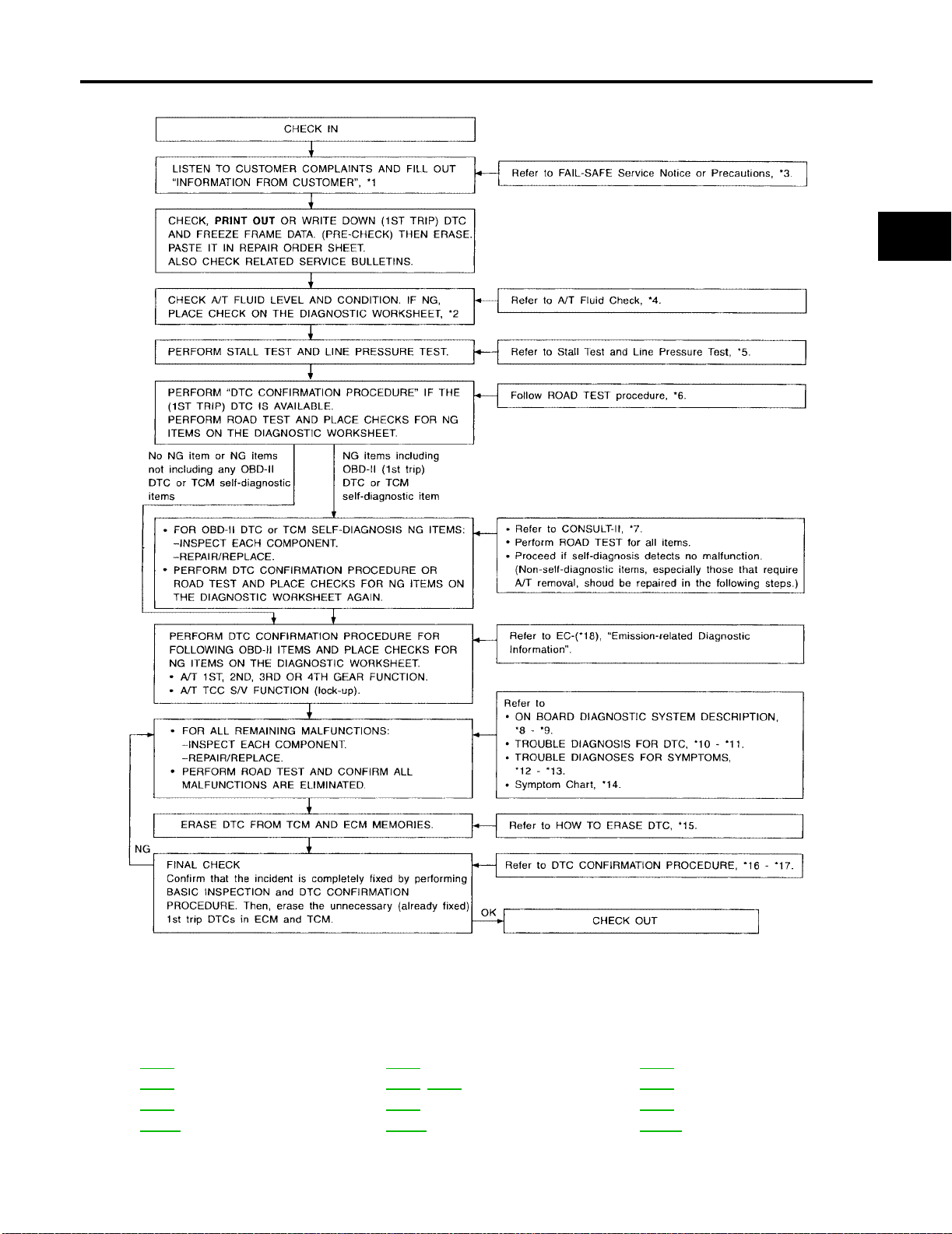
WORK FLOW CHART
TROUBLE DIAGNOSIS - INTRODUCTION
[RE4F04B]
A
B
AT
D
E
F
G
H
K
M
I
J
L
SAT086JI
*1: AT-65 *2: AT-66 *3: AT-12
*4: AT-71 *5: AT-74, AT-77 *6: AT-78
*7: AT-48 *8: AT-44 *9: AT-44
*10: AT-110 *11: AT-211 *12: AT-213
Revision: July 2005 2006 Altima
AT-69
Page 92

TROUBLE DIAGNOSIS - INTRODUCTION
[RE4F04B]
*13: AT-254 *14: AT-93 *15: AT-46
*16: AT-110 *17: AT-194 *18: ! Hyper-link Error ! , ! Hyper-link
Error !
Revision: July 2005 2006 Altima
AT-70
Page 93
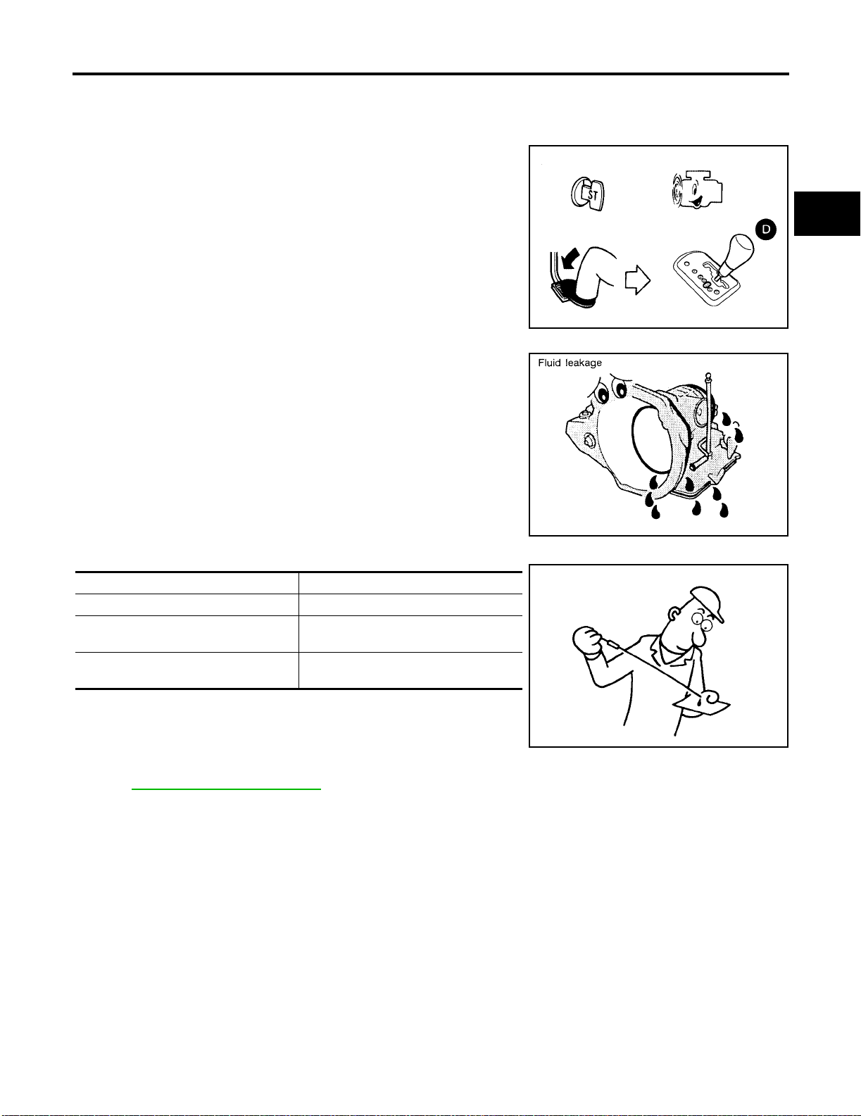
TROUBLE DIAGNOSIS - BASIC INSPECTION
[RE4F04B]
TROUBLE DIAGNOSIS - BASIC INSPECTION PFP:00000
A/T Fluid Check
FLUID LEAKAGE CHECK
1. Clean area suspected of leaking. — for example, mating surface
of converter housing and transa xle case.
2. Start engine, apply foot bra ke, pl ace selec tor l ever in D position
and wait a few minutes.
3. Stop engine.
ECS00968
A
B
AT
D
4. Check for fresh leakage.
FLUID CONDITION CHECK
Fluid color Suspect ed pro bl em
Dark or black with burned odor Wear of frictional ma teri al
Milky pink
Varnished fluid, light to dark brown and
tacky
Water contamination — Road water
entering through filler tube or breather
Oxidation — Over or under filling, —
Overheating
WCIA0053E
SAT288G
SAT638A
E
F
G
H
I
J
K
L
FLUID LEVEL CHECK
Refer to AT-398, "Checking A/T Fluid" .
A/T Fluid Cooler Cleaning
ECS00969
Whenever an au tomatic transaxle is repaired, overhauled, or replaced, the A/T fluid cooler mounted in the
radiator must be inspected and cleaned.
Metal debris and fri ct ion ma teri al, i f pres ent, can beco me trapp ed i n the A/T fl uid c oole r. This debris ca n co ntaminate the newly serviced A/T or, in severe cases, can block or restrict the flow of A/T fluid. In either case,
malfunction of the newly serviced A/T may result.
Debris, if present, may build up as A/T fluid enters the cooler inlet. It will be necessary to back flush the cooler
through the cooler outlet in order to flush out any built up debris.
A/T FLUID COOLER CLEANING PROCEDURE
1. Position an oil pan under the automatic transaxl e's inlet and out let cooler hoses.
2. Identify the inlet and outlet fluid cooler hoses.
Revision: July 2005 2006 Altima
AT-71
M
Page 94
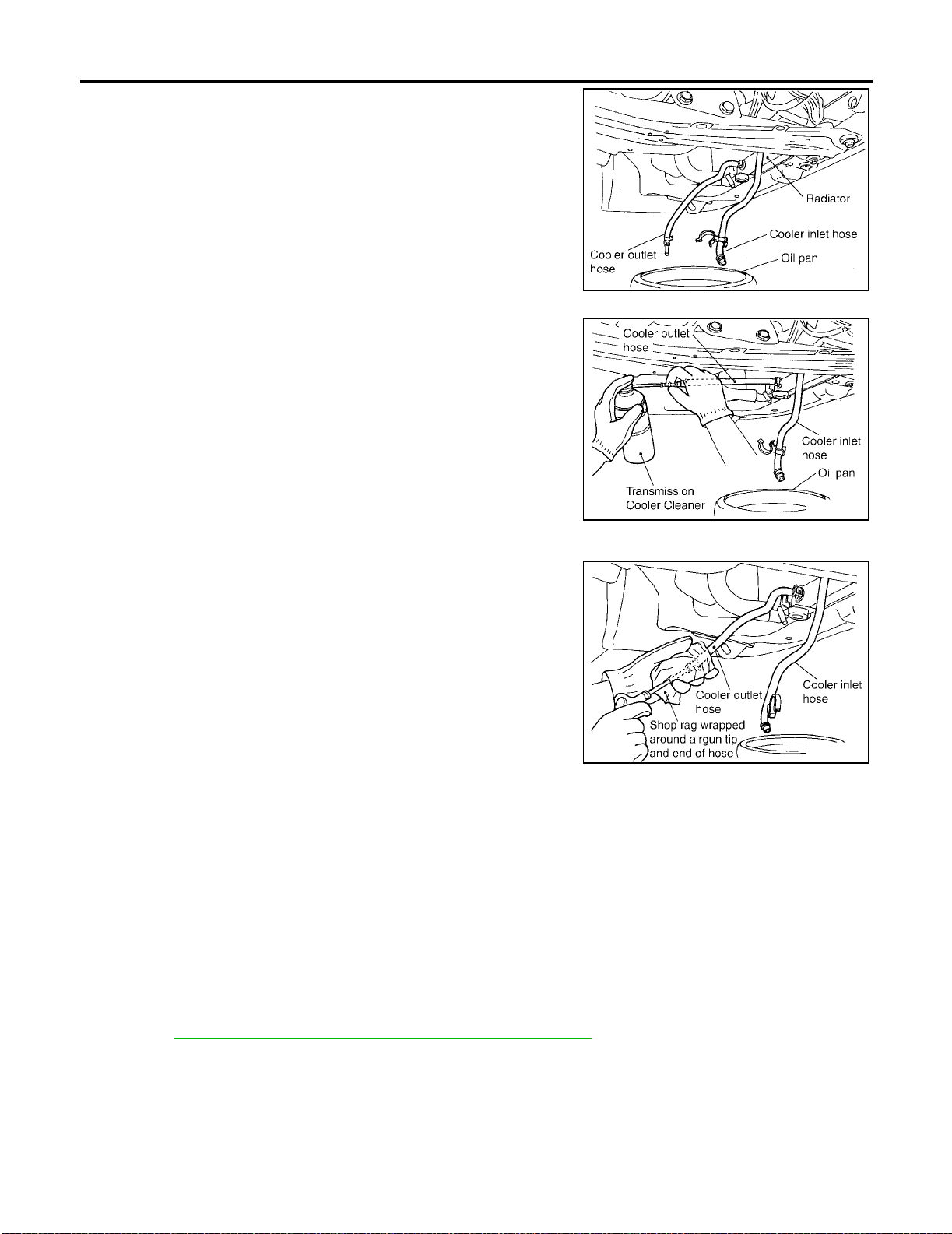
TROUBLE DIAGNOSIS - BASIC INSPECTION
3. Disconnect t he fl uid co oler inl et and outl et ru bber hos es fro m the
steel cooler tubes or bypass valve.
NOTE:
Replace the cooler hoses if rubber material from the hose
remains on the tube fitting.
4. Allow any A/T fluid that rem a in s i n the cooler hoses to drain int o
the oil pan.
5. Insert the extension adapter hose of a can of Transmission
Cooler Cleaner (Nissa n P/N 999M P-AM0 06) into the co oler ou tlet hose.
CAUTION:
● Wear safety glasses and rubber gloves when spraying
the Transmission Cooler Cleaner.
● Spray cooler cleaner only with adequate ventilation.
● Avoid contact with eyes and skin.
● Do not breath vapors or spray mist.
6. Hold the hose and can as high as possible and spray Transmission Cooler Cleaner in a continuous stream into the cooler outlet
hose until fluid flows out of the cooler inlet hose for 5 seconds.
7. Insert the tip of an air gun into the end of the cooler outlet hose.
8. Wrap a shop rag around the air gun tip and of the cooler outlet
hose.
[RE4F04B]
SCIA2945E
SCIA2955E
SCIA2962E
9. Blow compresse d air regulated to 5 - 9 kg/c m
2
(70 - 130 psi) through the cooler outlet hose for 10 sec-
onds to force out any remaining fluid.
10. Repeat steps 5 through 9 three additional times.
11. Position an oil pan under the banjo bolts that connect the fluid cooler steel lines to the transaxle.
12. Remove the banjo bolts.
13. Flush each steel line from the cooler side back toward the transaxle by spraying Transmission Cooler
Cleaner in a continuous stream for 5 seconds.
14. Blow compress ed air re gu la te d to 5 - 9 k g/c m
2
(70 - 130 psi) through each steel line from the cooler side
back toward the transaxle f or 10 seconds to force out any remai ning fluid.
15. Ensure all debris is removed from the steel cooler lines.
16. Ensure all debris is removed from the banjo bolts and fittings.
17. Perform AT-72, "
A/T FLUID COOLER DIAGNOSIS PROCEDURE" .
A/T FLUID COOLER DIAGNOSIS PROCEDURE
NOTE:
Insufficient cleaning of the cooler inlet hose exterior may lead to inaccurate debris identification.
1. Position an oil pan under the automatic transaxle's inlet and outlet coole r hoses.
2. Clean the exterior and tip of the cooler inlet ho se.
Revision: July 2005 2006 Altima
AT-72
Page 95
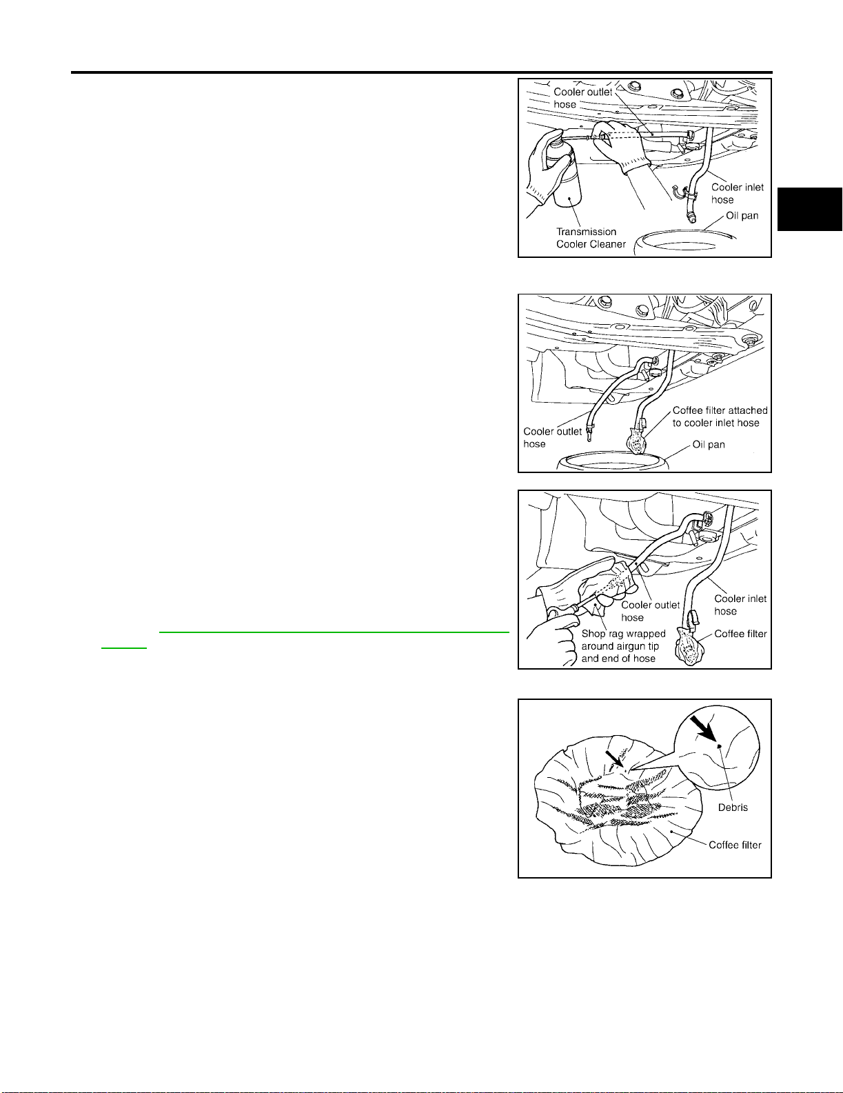
TROUBLE DIAGNOSIS - BASIC INSPECTION
3. Insert the extension adapter hose of a can of Transmission
Cooler Cleaner (Nissan P/N 99 9MP-AM00 6) into the coole r outlet hose.
CAUTION:
● Wear safety glasses and rubber gloves when spraying
the Transmission Cooler Cleaner.
● Spray cooler cleaner only with ad equ ate venti lation.
● Avoid contact with eyes and skin.
● Do not breat h vapors or spr ay mist.
4. Hold the hose and can as high as possible and spray Transmission Cooler Cleaner in a continuous stream into the cooler outlet
hose until fluid flows out of the cooler inlet hose for 5 seconds.
5. Tie a common white, basket-type coffee filter to the end of the
cooler inlet hose.
[RE4F04B]
A
B
AT
SCIA2955E
D
E
F
G
6. Insert the tip of an air gun into the end of the cooler outlet hose.
7. Wrap a shop rag around the air gun tip and end of cooler outlet
hose.
2
8. Blow compressed air regulated to 5 - 9 kg/cm
(70 - 130 psi)
through the cool er outlet hose to force any remaining A/T fluid
into the coffee filter.
9. Remove the coffee filter from the end of the cooler inlet hose.
10. Perform AT-73, "
A/T FLUID COOLER INSPECTION PROCE-
DURE" .
A/T FLUID COOLER INSPECTION PROCEDURE
1. Inspect the coffee filter for debris.
a. If smal l metal debris less than 1mm (0.040 in) in size or metal
powder is found in the coffee filter, this is normal. If normal
debris is found, the A/T fluid cooler/radiator can be re-used and
the procedur e is ended.
SCIA2965E
H
I
J
K
SCIA2966E
L
M
SCIA2967E
Revision: July 2005 2006 Altima
AT-73
Page 96
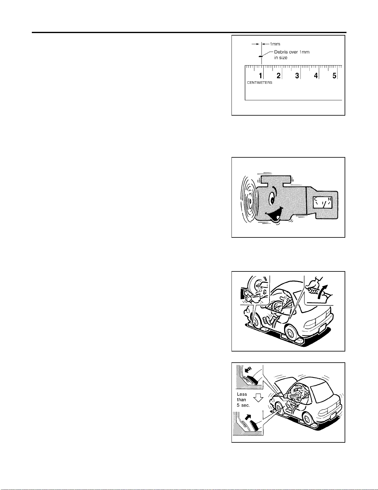
TROUBLE DIAGNOSIS - BASIC INSPECTION
b. If one or more pi eces of debris a re found that are ov er 1mm in
size and/or peel ed clutch facing mater ial is found in the coffee
filter, the fluid cooler is not serviceable. The radiator/fluid cooler
must be replaced and the inspection procedure is ended.
A/T FLUID COOLER FINAL INSPECTION
After performing all proced ures, ensure th at all remaining oil is cleaned f rom all components.
[RE4F04B]
SCIA2971E
Stall Test
STALL TEST PROCEDURE
1. Check A/T fluid and engine oil levels. If necessary, add fluid and
oil.
2. Drive vehicle for approximately 10 minutes or until fluid a nd oil reach operating temperature.
ATF operating temperature :50 - 80°C (122 - 176°F)
3. Set parking brake and block wheels.
4. Install a tachometer where it can be seen by driver during test.
● It is good practice to mark the point of specified engine
rpm on indicator.
ECS0096A
SAT647B
SAT513G
5. Start engine, apply foot brake, and place selector lever in D
position.
6. Accelerate to wide open throttle gradually while applying foot
brake.
7. Quickly no te th e e ng in e s tall revolution and im me diately release
throttle.
● During test, never hold throttle wide open for more than 5
seconds.
Stall revolution : 2,300 - 2,750 rpm
SAT514G
Revision: July 2005 2006 Altima
AT-74
Page 97
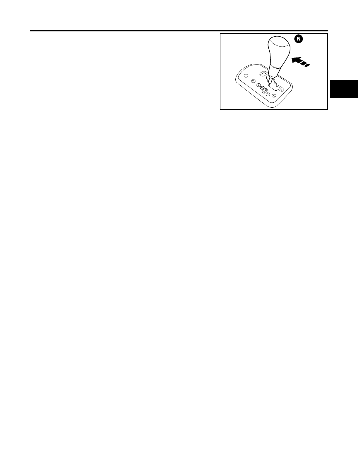
TROUBLE DIAGNOSIS - BASIC INSPECTION
[RE4F04B]
8. Move selector lever to N position.
9. Cool off ATF.
● Run engine at idle for at least one minute.
10. Repeat steps 5 through 9 with selector lever in 2, 1 and R positions.
LCIA0064E
JUDGEMENT OF STALL TEST
The test resu lt an d p oss ibl e da mag ed c ompon en ts relating t o e ac h re su lt ar e sh own in th e i l lu str at ion s o n ne xt
page.
In order to pinpoint the possible damaged components, refer to AT-69, "
NOTE:
Stall revolution is too high in D, 2 or 1 position:
● Slippage occurs in 1st gear but not in 2nd and 3rd gears. ..... Low one-way clutch slippage
● Slippage occurs in the following gears:
1st through 3rd gears in 3 position and engine brake functions.
1st and 2nd gea rs in 2 posit ion and engi ne brake fun ctions with ac celerator peda l released (fu lly closed
throttle). ..... Forward clutch or forward one-way clutch slippage
Stall revolution is too high in R position:
● Engine brake does not function in 1 position. ..... Low & reverse brake slippage
● Engine brake functions in 1 position. ..... Reverse clutch slippage
Stall revolution within specifications:
● Vehicle does not achiev e speed of more than 80 km/h (50 MPH). ..... One-way clutch seizure in torque
converter housing
CAUTION:
Be careful since automatic fluid temperat ure increases ab normally.
● Slippage occurs in 3rd and 4th gears in D position. ..... High clutch slippage
● Slippage occurs in 2nd and 4th gear in D position. ..... Brake band slippage
● Engine brake does not function in 2nd and 3rd gears in D position, 2nd gear in 2 position, and 1st gear in
1 position.
Stall revolution less than specifications:
WORK FLOW CHART" .
A
B
AT
D
E
F
G
H
I
J
K
L
Revision: July 2005 2006 Altima
AT-75
M
Page 98
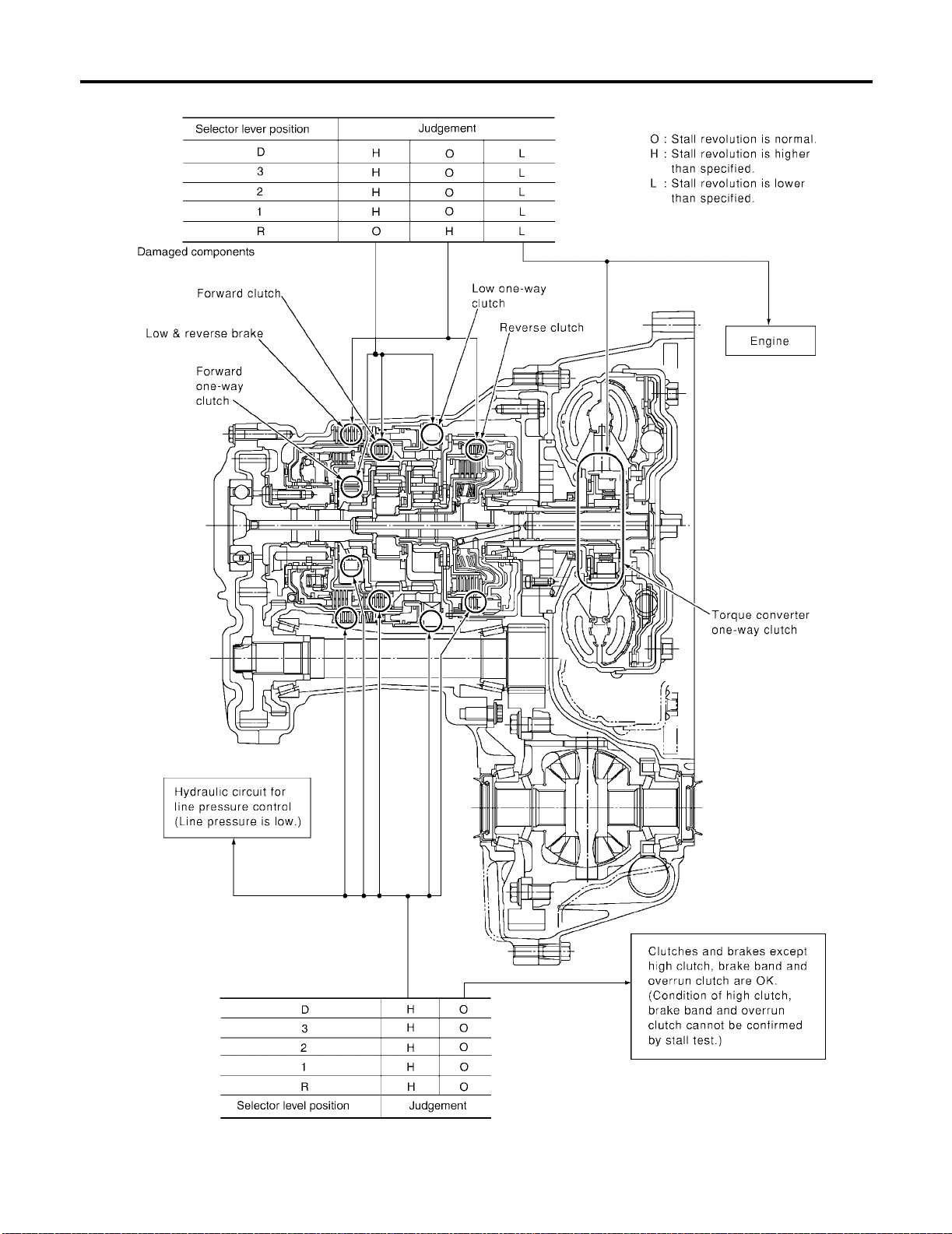
TROUBLE DIAGNOSIS - BASIC INSPECTION
● Poor acceleration during starts. ..... One-way clutch seizure in torque converter
[RE4F04B]
SCIA3256E
Revision: July 2005 2006 Altima
AT-76
Page 99
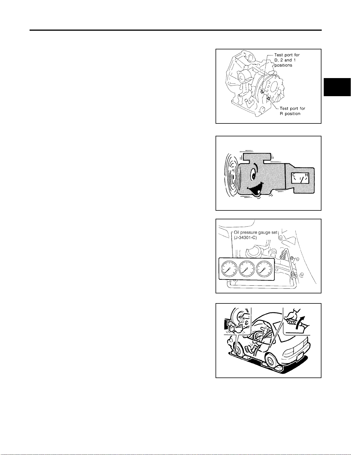
TROUBLE DIAGNOSIS - BASIC INSPECTION
[RE4F04B]
Line Pressure Test
LINE PRESSURE TEST PORTS
Location of line pressure test ports are sho wn in the illustr ation.
● Always replace pressure plugs as they are self-sealing
bolts.
LINE PRESSURE TEST PROCEDURE
1. Check A/T fluid and engine oil levels. If necessary, add fluid and
oil.
2. Drive vehicle for approximately 10 minutes or until fluid and oil
reach operating temperature.
ATF operating temperature :50 - 80°C (12 2 -
176°F)
ECS0096B
A
B
AT
D
SAT301FA
E
F
G
H
SAT647B
3. Install pres s ure gaug e to co rres p on din g lin e pre ssure port .
4. Set parking brake and block wheels.
● Continue to depress bra ke pe da l fu lly w hi le line p res sure
test is being performed at stall speed.
SCIA5376E
SAT513G
I
J
K
L
M
Revision: July 2005 2006 Altima
AT-77
Page 100
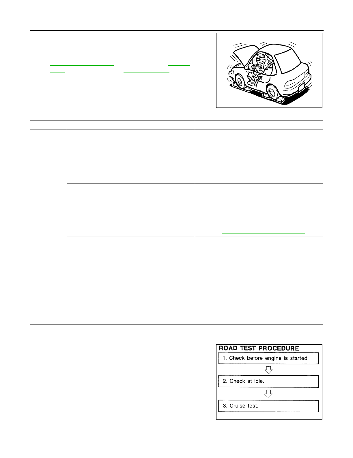
TROUBLE DIAGNOSIS - BASIC INSPECTION
5. Start engine and measure line pressure at idle and stall speed.
● When measuring line press ure at stall speed, follow the
stall test procedure.
[RE4F04B]
AT-77, "
Test"
Line Pressure
: Refer to SDS, AT-379,
"Line Pressure"
JUDGEMENT OF LINE PRESSURE TEST
Judgement Suspected parts
Line pressure is low in all positions.
Line pressure is low in particular position.
At idle
Line pressure is high.
Line pressure is low.
At stall speed
SAT493G
● Oil pump wear
● Control piston damage
● Pressure regulator valv e or plug stic ki ng
● Spring for pressure regulat or valve damaged
● Fluid pressure leakage bet w een oil strain er an d pres -
sure regulator valve
● Clogged strainer
● Fluid pressure leakage between manual valve and par-
ticular clutch
● For example, line pressure is:
− Low in R and 1 positions, but
− Normal in D and 2 positions.
Therefore, fluid leakage exists at or around low and
reverse brake circuit.
Refer to AT-27, "
● A/T fluid temperature sensor dama ged
● Line pressure solenoid val ve st icki ng
● Short circuit of line pressure solenoid valve circuit
● Pressure modifier val ve sti cki ng
● Pressure regulator valv e or plug stic ki ng
● Open in dropping resistor cir cui t
● Line pressure solenoid val ve st icki ng
● Short circuit of line pressure solenoid valve circuit
● Pressure regulator valv e or plug stic ki ng
● Pressure modifier val ve sti cki ng
● Pilot valve sticking
CLUTCH AND BAND CHART" .
Road Test
ECS0096C
DESCRIPTION
● The purpose of the test is to determine overall performance of A/
T and analyze causes of problems .
● The road test consists of the following three parts:
1. Check before engine is started
2. Check at idle
3. Cruise test
SAT786A
Revision: July 2005 2006 Altima
AT-78
 Loading...