

Page 1

Nintendo Entertainment
System Documentation
Version 1.0
August 2004
Patrick Diskin
Page 2

Preface
Abstract
The Nintendo Entertainment System (NES) was the world’s most widely used videogames
console during the 1980s. From its initial release in 1983 until it was discontinued in 1995 the
console brought gaming into more homes than ever before and paved the way for the
videogame industry as it stands today.
Although technology has improved dramatically since the NES, many excellent games were
only released on that format and so are unplayable on more modern systems. However
these games have been able to survive and continue to be played thanks to emulation, which
simulates the workings of one system in order to allow software created for it to be used on a
modern system.
This document describes both the hardware in the NES and some of the devices used with it.
It also briefly discusses emulation and issues relating to this. Much of the contents of this
document appeared earlier in [1].
The document makes use of the hexadecimal and binary numbering systems. The reader is
assumed to have some knowledge of these numbering systems but a brief explanation of
some issues is presented in Appendix A.
Acknowledgements
The information contained within this document is based on the work of the many others
involved in NES emulation. I would like to acknowledge the authors of all the documents
listed in the References section but particularly:
• Andrew John Jacobs for his invaluable information on the 6502 processor [2], [3] and [4].
• Chris Covell for ‘NES Technical / Emulation / Development FAQ’ [5].
• Firebug for ‘Comprehensive NES Mapper Document’ [6].
• Jeremy Chadwick for ‘Nintendo Entertainment System Documentation’ [7].
• Loopy for ‘The Skinny on NES Scrolling’ [8].
• Marat Fayzullin for ‘Nintendo Entertainment System Architecture’ [9].
• Everybody involved with nesdev.parodius.com.
2
Page 3
1 - Introduction
1.1 Nintendo Entertainment System History
In 1889, Fusajiro Yamauchi founded Nintendo Koppai and began manufacturing Japanese
playing cards, hanafuda, in Kyoto [10]. By 1950, when Hiroshi Yamauchi became president,
Nintendo was a successful manufacturer of both western and Japanese playing cards. In
1963, after several name changes, the company settled on Nintendo Co. Ltd. (NCL). By
1970, the company was producing electronic games and in 1973 they introduced a laser clay
shooting system which they hoped would replace bowling as a major pastime [11].
Nolan Bushnell was a student at the University of Utah when he first had the idea of a coin
operated computer game. Pong, which was released in 1972, quickly became a hit and
inspired the release of a wave of arcade games. Bushnell’s company, Atari, wanted to
replicate this success by releasing a system to play games in homes. By 1976 several
companies had tried, and failed, to release a successful console. Bushnell was aware that
Atari lacked the capital to produce a console and sold the company to Warner
Communications, retaining the position of chairman [12].
In 1977, Atari released the Atari Video Computer System (VCS), an 8-bit console which
succeeded in opening up the home console market, aided by the home version of Space
Invaders, released in 1980. Bushnell disagreed with the direction Warner were taking and left
the company in 1978.
In 1979, Nintendo made their first attempt to break into the arcade game market but by 1981
their success had been limited. Hiroshi Yamauchi asked Nintendo graphic artist, Shigeru
Miyamoto, to design a new game. The result was Donkey Kong in which players controlled a
carpenter called Jumpman and tried to rescue a captive girl from Donkey Kong, a large ape.
Jumpman was renamed Mario after the landlord of Nintendo’s newly created American
subsidiary, later to be called Nintendo of America Inc. (NOA), run by Yamauchi’s son in law,
Minoru Arakawa.
By 1982, third party development had led to several sub-standard games being released for
Atari’s VCS and competition with other consoles was leading to saturation of the market. By
1984 the industry was suffering enormous losses and most product lines were discontinued.
Nintendo, meanwhile, had enjoyed success in the arcade market and in the home market
with the Colour TV Game 6. The Japanese console market was still doing well and Yamauchi
felt that Nintendo could become the market leaders through a combination of quality games
and improved hardware sold at a lower price than competitors (profit would be made on the
games).
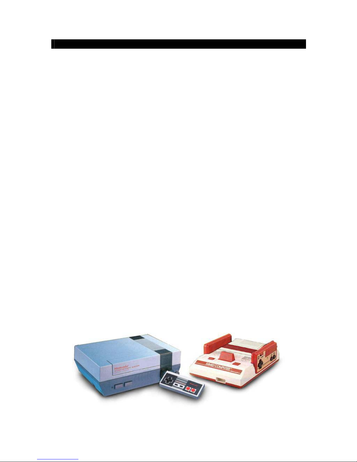
Figure 1-1. The Nintendo Entertainment System and the Famicom [13].
3
Page 4

The Famicom (Family Computer) became an enormous success in Japan and in 1983,
Minoru Arakawa offered Atari the chance to produce the system in America. When it became
clear that Atari did not have the resources to proceed the deal fell through. Atari was divided
up and sold by Warner while Nintendo decided to produce and market the Famicom in
America themselves under the name Nintendo Entertainment System (NES). The console
was also redesigned to appeal to western children as shown in figure 1-1.
Despite early resistance from retailers fearing further losses after the industry crash the
previous year, the NES became available in America in 1985. As a result of strict quality
controls on third party software, combined with Nintendo’s own games (including Super
Mario Bros., The Legend of Zelda and Metroid) the console became a huge success.
In 1987, the NES became the top selling toy in America, while The Legend of Zelda became
the first NES game to achieve sales of one million units. In America alone, revenues for
Super Mario Bros. 3 were in excess of $500 million with over 7 million units sold and 4 million
in Japan [14]. In 1991, Nintendo earned about $1.5 million for each of its 5,000 employees.
The company’s profit in the early 1990s exceeded that of the American film industry. Such
was Nintendo’s effect on American culture that a 1990 survey showed that Mario was more
recognized by children than Mickey Mouse.
Sega released the 16-bit Genesis (Mega Drive in Europe) in 1989 and, due to the success of
Sonic the Hedgehog, the console became very popular. That same year, Nintendo were
busy with the release of their handheld console, the Game Boy but would enter the 16-bit
market with the Super Famicom in 1990. The console was released in America in 1991 as
the Super Nintendo Entertainment System (SNES) and due to incompatibility with the NES
hardware, signalled a move away from the old system.
In 1993, Nintendo released a redesigned version of the NES (as shown in figure 1-2) but the
last NES game, Wario’s Woods was released in late 1994 and the system was officially
discontinued in 1995 [16]. By this time over 60 million NES consoles and 500 million games
had been sold worldwide.
The SNES featured a 65816 processor which was largely compatible with the NES’ 6502
processor. However the graphics and sound on the new system were incompatible [5]. This
made it impossible for games created for the old system to run on its successor. As a result
the software created for the NES could no longer be used by people who did not already
Figure 1-2. Redesigned NES
released in 1993 [15].
4
Page 5

have a NES, preventing many people from using the software. In addition, all hardware has a
limited lifespan and eventually there will be no working NES consoles to still play the games
on. The games themselves often featured battery backed RAM to enable progress to be
saved and Nintendo only predicted the battery life as five years. There are multiple options
which allow the continued use of NES games and these are described here.
1.2 Conversion
Although the exact implementations of computer systems is different, many of the principles
are the same. A PC cannot execute the instructions written for the NES because it does not
understand them. However, it is likely that comparable instructions do exist for the PC.
Therefore, it is possible to rewrite the software for a different system and to replicate the
graphics and sound of the original. Converting the software in this way is essentially
simulation [17]. The software appears to behave the same as the original but the
implementation may be quite different.
Converting the software has the advantage that the resulting software will perform well, since
it is produced for the target architecture. However, the process is time consuming and needs
to be done for each game individually.
1.3 Emulation
Emulation is the process of simulating hardware to enable the software developed for it to be
used on an otherwise incompatible system. The following definition is by the British
Computer Society and is taken from [18]:
“Emulation is a very precise form of simulation which should mimic exactly the
behaviour of the circumstances that it is simulating. An emulator may enable
one type of computer to operate as if it were a different type of computer.“
Emulation is often used by the videogame industry to allow developers to begin writing
software for a new system before it is released. However, it can also be used to allow the
continuing use of old systems.
Hardware emulation involves producing a system with hardware compatible with the original.
In the case of the NES it would be possible to produce a system using a compatible
processor and to allow it to play the original game cartridges. This technique can also
provide good performance, provided compatibility is ensured, but few people have the skills
and resources required to construct the system.
Using hardware simulation software it is possible to half implement this technique. Software
is available which allows simulation of a detailed hardware design and this can be used to
recreate the system from a design without having to produce a real implementation. Such a
system is described in [19].
Software emulation requires producing software which will emulate the functions of a given
system. There are three approaches to software emulation [17]:
• Interpretation involves reading in the next instruction for the system being emulated,
translating it to an instruction (or a number of instructions) for the target architecture and
executing it. Though this is accurate, due to translating during execution the process can
lead to noticeable degradation of performance compared to the original system if the
speed of the target system is low.
5
Page 6

• Static translation involves reading in the whole of the source program and translating it
for the target system, producing a program that is executable on that system. However it
is not always possible to determine how a program will execute from a static analysis of
it. Branch instructions, for example, often depend on the contents of memory locations
which can only be determined at run-time [20].
• Dynamic translation works in much the same way as static translation but occurs while
executing the program. This allows it to account for branch and jump instructions and to
produce accurate code [20].
The NES is perhaps the most widely emulated console with a number of emulators already
available of varying quality. Writing a NES emulator remains a very challenging project,
requiring a detailed understanding of how the system works. A fairly comprehensive list of
available NES emulators can be found at [21] although many of these have been
discontinued. The basics of writing an emulator are described by [17] and [22], both of which
focus specifically on the NES.
1.4 Legal
Emulation is considered to be something of a legal grey area. Emulators are not illegal,
provided all the information used in the development is legally obtained and does not contain
any proprietary code. However, it is illegal to run any software which you do not own a
licence for.
Copying NES games is possible with the correct hardware. Such copiers dump the contents
of the game cartridges to a disk to enable access by a computer. There are a wide variety of
copiers, which function in different ways. Figure 1-3 shows ChameleonNES which copies the
contents of a cartridge to a PC via a USB port. Copyright law typically allows for a backup
copy to be made, however this does not apply to games stored on permanent semiconductor
chips such as those used by the NES. These copying devices are illegal.
Figure 1-3. ChameleonNES cartridge copier [23].
Most emulator users download games from the Internet since they do not have access to the
required copying hardware. These websites usually cover themselves with an agreement
that you can only download a file if you own the original game or if you will delete it within 24
hours. This may make the process look legal but, since the copies are illegal, it is clearly not.
Even if the law allowed for making a backup copy of a NES game, copies can only be made
and used by the original owner, so downloading files off the Internet would still be illegal.
6
Page 7
This only applies to games which were originally made for the NES itself. Many developers
have produced games since which have been released freely on the Internet. Downloading
these is acceptable. As for original NES games, using them will remain illegal until either the
developers grant permission for their use or the copyright expires, which is 75 years after
they were made.
Nintendo are very much against emulation. The company acted against the developers of
UltraHLE [24], an emulator for their Nintendo 64 console, which they claimed violated
copyright. Nintendo’s objection was understandable as the console was still in use when
UltraHLE was released. The presence of Nintendo 64 emulators represented a threat to
Nintendo’s income however, many believe that the law should make an exception for
systems which are no longer in production and from which Nintendo no longer make any
money. Despite emulation’s ability to keep old games alive Nintendo refuse to release the
copyright on old games so their use remains illegal.
For more information on the legal issues of emulation, the reader is directed to Nintendo’s
own FAQ on the subject [25]. This is highly biased and ignores the legal uses of emulation.
For a detailed response and clarification on this, the reader should look at [26].
1.5 NES Hardware Overview
Hiroshi Yamauchi’s instructions to
design a console which would be
cheaper than the competition resulted in
Nintendo deciding to use an outdated
Central Processing Unit (CPU).
Although a 16-bit processor would have
coped with ease, to keep the price low
they decided to use a variant of the 8-bit
6502 processor, developed by MOS
technology in 1975. The chip would be
sufficient to run the programs but would
be unable to generate the graphics
required so the company decided to use
a second chip as a dedicated Picture
Processing Unit (PPU), responsible for
calculating and displaying the graphics.
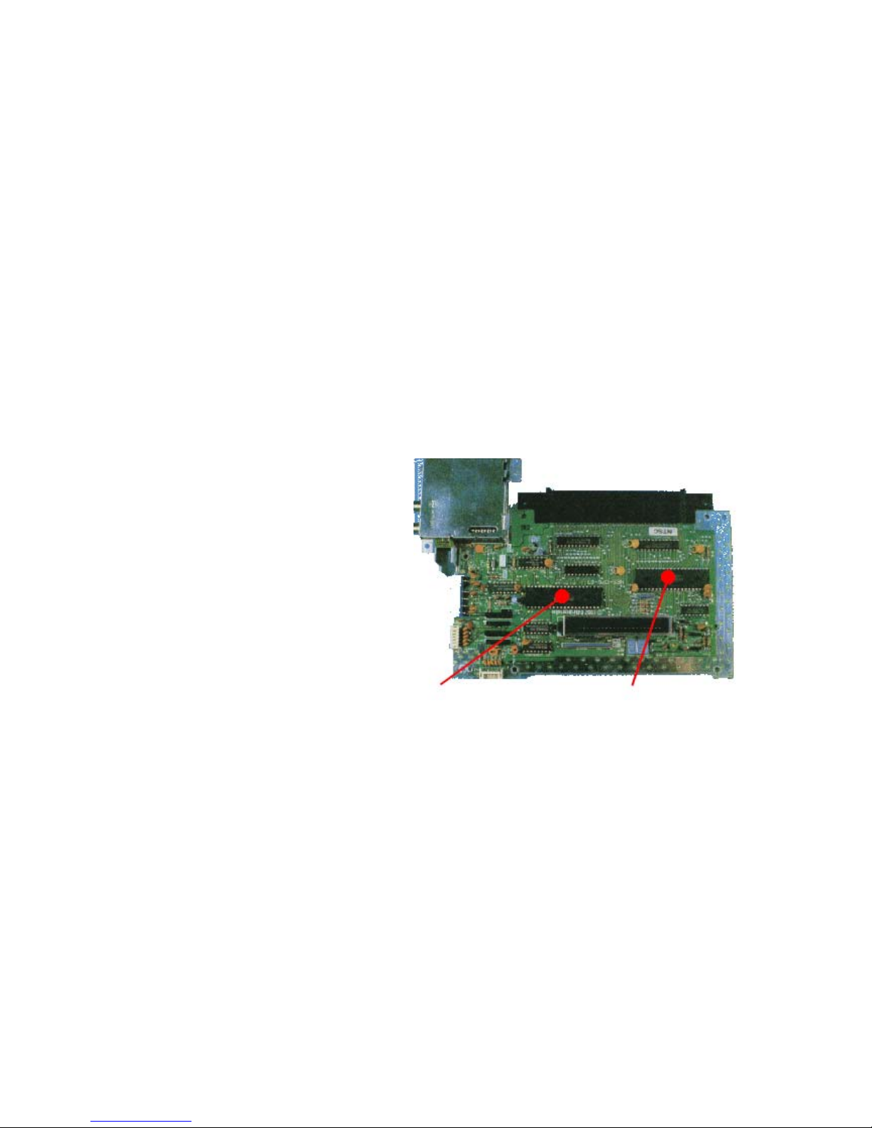
PPU CPU
Figure 1-4 shows the top of the
motherboard with the CPU and PPU
Figure 1-4. The NES motherboard [27].
indicated.
Nintendo designed the basic features required from the chips but found it difficult to find a
company willing to produce such highly customised chips for the low price they were looking
for. Ricoh agreed to manufacture the chips after Nintendo guaranteed them a three-million
chip order. By the end of 1986 Nintendo was Ricoh’s largest customer, accounting for
between 60 and 70 percent of the company’s semiconductor sales [10]. The functionality of
the CPU is discussed in Part 2, that of the PPU is discussed in Part 3.
Both chips feature their own internal memory, in the form of RAM. Games were usually
stored on ROM chips within the game cartridges, which could be accessed by the CPU when
the cartridges where inserted into the system. The hardware used for games is discussed in
Part 4.
The NES used memory mapped I/O to allow the processor to communicate with the other
components, the PPU and the input devices. Memory mapped I/O is a technique where data
7
Page 8

can be transferred to a device via a write to a specific location in memory. Input devices are
discussed in Part 5, the function of the memory mapped I/O is discussed throughout the
document and specifically in Appendix B.
8
Page 9

2 - Central Processing Unit
2.1 2A03 Overview
Ricoh produced an NMOS processor based on the 6502, the 2A03. The chip differed from a
standard 6502 in that it had the ability to handle sound, serving as pAPU (pseudo-Audio
Processing Unit) as well as CPU, and that it lacked a Binary Coded Decimal (BCD) mode
which allowed representing each digit using 4 bits. For the purposes of programming, the
2A03 uses the same instruction set as the standard 6502 which is shown in figure 2-1. The
6502 is a little endian processor which means that addresses are stored in memory least
significant byte first, for example the address $1234 would be stored in memory as $34 at
memory location x and $12 at memory location (x + 1).
Figure 2-1. The 6502 processor [28].
2.2 CPU Memory Map
Figure 2-2 shows how the CPU accesses memory using buses. The memory is divided into
three parts, ROM inside the cartridges, the CPU’s RAM and the I/O registers. The address
bus is used to set the address of the required location. The control bus is used to inform the
components whether the request is a read or a write. The data bus is used to read or write
the byte to the selected address. Note that ROM is read-only and is accessed via a MMC, to
allow bank switching to occur. The I/O registers are used to communicate with the other
components of the system, the PPU and the control devices.
Figure 2-2. Processor diagram.
9
Page 10

The 2A03 had a 16-bit address bus and as such could support 64 KB of memory with
addresses from $0000-$FFFF. Figure 2-5 is the CPU memory map used by the NES,
showing the layout of memory. The left hand map is a simplified version showing the major
sections, while the map to the right divides these sections further.
Zero Page refers to addresses in the range $0000-$00FF, that is the first page in memory
and is used by certain addressing modes to allow quicker execution [4]. Memory locations
$0000-$07FF are mirrored three times at $0800-$1FFF. This means that, for example, any
data written to $0000 will also be written to $0800, $1000 and $1800. The memory mapped
I/O registers are located at $2000-$401F. Locations $2000-$2007 are mirrored every 8 bytes
in the region $2008-$3FFF and the remaining registers follow this mirroring. SRAM (WRAM)
is the Save RAM, the addresses used to access RAM in the cartridges for storing save
games.
From $8000 onwards is the addresses allocated to cartridge PRG-ROM. Games with only
one 16 KB bank of PRG-ROM will load it into both $8000 and $C000. This is to ensure that
the vector table is located in the correct addresses. Games with two 16 KB PRG-ROM banks
will load one into $8000 and the other into $C000. Games with more than two banks use
memory mappers to determine which banks to load into memory. The memory mapper
monitors memory writes for a specific address (or range of addresses) and when that
address is written to, it performs a bank switch. The details vary between different memory
mappers and more information can be found in Appendix D.
10
Page 11

2.3 Registers
The 6502 has fewer registers than similar processors. There are three special purpose
registers, the program counter, stack pointer and status register which each have a specific
use. It also has three general purpose registers, the accumulator and the index registers, X
and Y, which can be used to store data or control information temporarily.
2.3.1 Program Counter (PC)
The program counter is a 16-bit register which holds the address of the next instruction to be
executed. As instructions are executed, the value of the program counter is updated, usually
moving on to the next instruction in the sequence. The value can be affected by branch and
jump instructions, procedure calls and interrupts.
2.3.2 Stack Pointer (SP)
Figure 2-3. CPU memory map.
11
Page 12

The stack is located at memory locations $0100-$01FF. The stack pointer is an 8-bit register
which serves as an offset from $0100. The stack works top-down, so when a byte is pushed
on to the stack, the stack pointer is decremented and when a byte is pulled from the stack,
the stack pointer is incremented. There is no detection of stack overflow and the stack
pointer will just wrap around from $00 to $FF.
2.3.3 Accumulator (A)
The accumulator is an 8-bit register which stores the results of arithmetic and logic
operations. The accumulator can also be set to a value retrieved from memory.
2.3.4 Index Register X (X)
The X register is an 8-bit register typically used as a counter or an offset for certain
addressing modes. The X register can be set to a value retrieved from memory and can be
used to get or set the value of the stack pointer.
2.2.5 Index Register Y (Y)
The Y register is an 8-bit register which is used in the same way as the X register, as a
counter or to store an offset. Unlike the X register, the Y register cannot affect the stack
pointer.
2.3.6 Processor Status (P)
The status register contains a number of single bit flags which are set or cleared when
instructions are executed.
• Carry Flag (C) - The carry flag is set if the last instruction resulted in an overflow from bit
7 or an underflow from bit 0. For example performing 255 + 1 would result in an answer
of 0 with the carry bit set. This allows the system to perform calculations on numbers
longer than 8-bits by performing the calculation on the first byte, storing the carry and
then using that carry when performing the calculation on the second byte. The carry flag
can be set by the SEC (Set Carry Flag) instruction and cleared by the CLC (Clear Carry
Flag) instruction.
• Zero Flag (Z) - The zero flag is set if the result of the last instruction was zero. So for
example 128 - 127 does not set the zero flag, whereas 128 - 128 does.
• Interrupt Disable (I) - The interrupt disable flag can be used to prevent the system
responding to IRQs. It is set by the SEI (Set Interrupt Disable) instruction and IRQs will
then be ignored until execution of a CLI (Clear Interrupt Disable) instruction.
• Decimal Mode (D) - The decimal mode flag is used to switch the 6502 into BCD mode.
However the 2A03 does not support BCD mode so although the flag can be set, its value
will be ignored. This flag can be set SED (Set Decimal Flag) instruction and cleared by
CLD (Clear Decimal Flag).
• Break Command (B) - The break command flag is used to indicate that a BRK (Break)
instruction has been executed, causing an IRQ.
• Overflow Flag (V) - The overflow flag is set if an invalid two’s complement result was
obtained by the previous instruction. This means that a negative result has been obtained
when a positive one was expected or vice versa. For example, adding two positive
numbers should give a positive answer. However 64 + 64 gives the result -128 due to the
sign bit. Therefore the overflow flag would be set. The overflow flag is determined by
taking the exclusive-or of the carry from between bits 6 and 7 and between bit 7 and the
carry flag [29]. An explanation of two’s complement can be found in Appendix A.
12
Page 13

• Negative Flag (N) - Bit 7 of a byte represents the sign of that byte, with 0 being positive
and 1 being negative. The negative flag (also known as the sign flag) is set if this sign bit
is 1.
The flags are arranged in the status register in the order shown in figure 2-3. Bit 5 of the
status register is unused.
Figure 2-4. Status register layout.
2.4 Interrupts
Interrupts prevent the standard sequential execution of code and cause the processor to
attend to the interrupt. Interrupts are usually generated by hardware which requires attention,
but can be triggered by software. The NES has three different types of interrupt, NMI, IRQ
and reset. The addresses to jump to when an interrupt occurs are stored in a vector table in
the program code at $FFFA-$FFFF. When an interrupt occurs the system performs the
following actions [30]:
1. Recognize interrupt request has occurred.
2. Complete execution of the current instruction.
3. Push the program counter and status register on to the stack.
4. Set the interrupt disable flag to prevent further interrupts.
5. Load the address of the interrupt handling routine from the vector table into the program
counter.
6. Execute the interrupt handling routine.
7. After executing a RTI (Return From Interrupt) instruction, pull the program counter and
status register values from the stack.
8. Resume execution of the program.
IRQs, or maskable interrupts, are generated by certain memory mappers. They are ignored
by the processor if the interrupt disable flag is set. IRQs can be triggered by the software by
use of the BRK (Break) instruction. When an IRQ occurs the system jumps to the address
located at $FFFE and $FFFF.
NMI (Non-Maskable Interrupt) is the type of interrupt generated by the PPU when V-Blank
occurs at the end of each frame. NMIs are not affected by the interrupt disable bit in the
status register, so execution is always interrupted when they occur [31]. However, triggering
of a NMI can be prevented if bit 7 of PPU Control Register 1 ($2000) is clear. When a NMI
occurs the system jumps to the address located at $FFFA and $FFFB. The handling of NMIs
is shown in figure 2-4.
Reset interrupts are triggered when the system first starts and when the user presses the
reset button. When a reset occurs the system jumps to the address located at $FFFC and
$FFFD.
The system gives the highest priority to reset requests, followed by NMI and finally IRQ [7].
The NES has an interrupt latency of 7 cycles, which means it takes 7 CPU cycles to begin
executing the interrupt handler.
13
Page 14
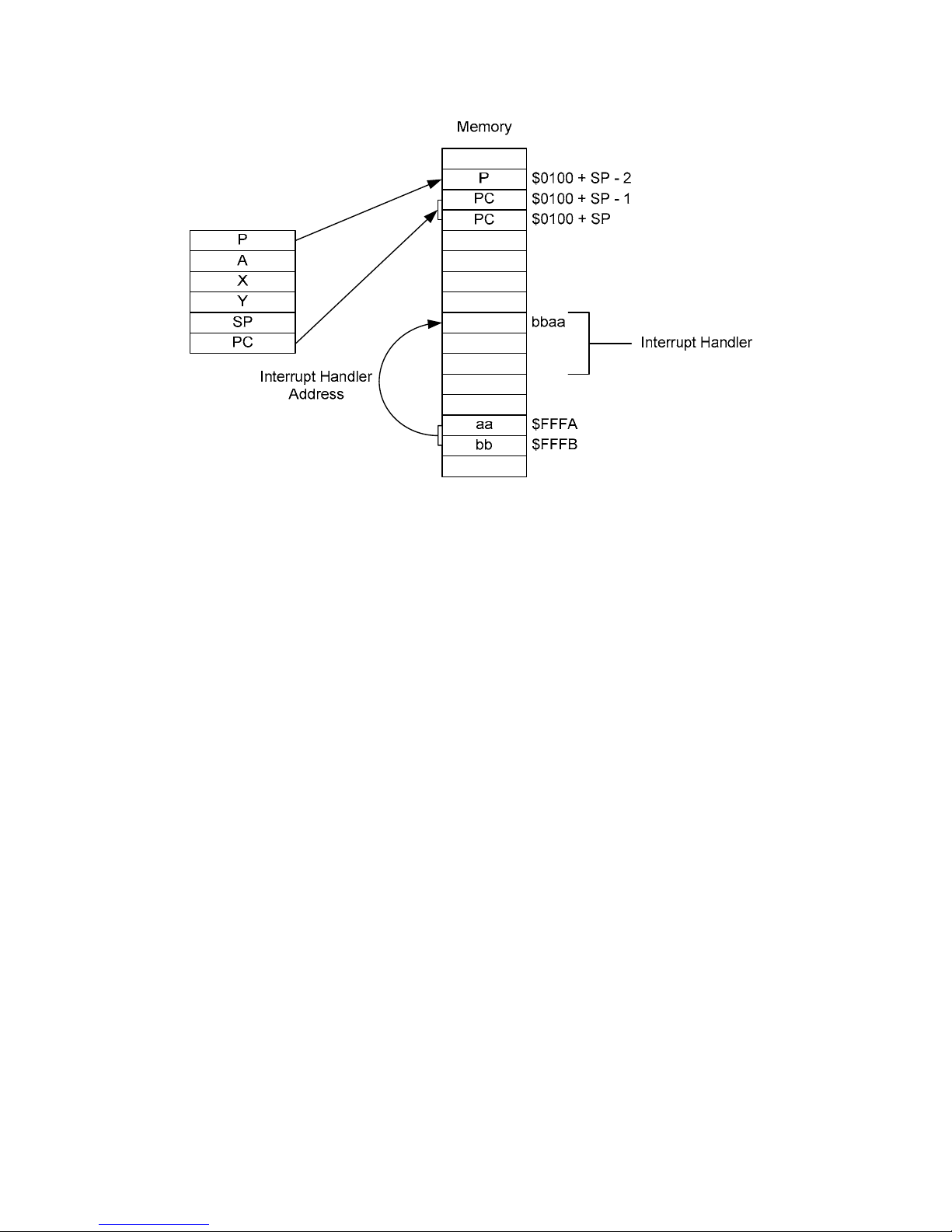
Figure 2-5. NMI (Non-Maskable Interrupt) handling.
2.5 Addressing Modes
The 6502 has several different addressing modes, providing different ways to access
memory locations. There are also addressing modes which operate on the contents of
registers, rather than memory. In total there are 13 different addressing modes on the 6502.
Some instructions can use more than one different addressing mode. Details on the available
addressing modes can be found in Appendix E.
2.6 Instructions
The 6502 has 56 different instructions although some come in multiple variations using
different addressing modes, making a total of 151 valid opcodes (operation codes) out of a
possible 256. A detailed explanation of the complete instruction set can be found in [2], [29]
and [32]. Instructions are either one, two or three bytes long, depending on the addressing
mode. The first byte is the opcode and the remaining bytes are the operands. Instructions fit
into several functional groups [3]:
• Load / Store Operations - Load a register from memory or stores the contents of a
register to memory.
• Register Transfer Operations - Copy contents of X or Y register to the accumulator or
copy contents of accumulator to X or Y register.
• Stack Operations - Push or pull the stack or manipulate stack pointer using X register.
• Logical Operations - Perform logical operations on the accumulator and a value stored in
memory.
• Arithmetic Operations - Perform arithmetic operations on registers and memory.
• Increments / Decrements - Increment or decrement the X or Y registers or a value stored
in memory.
• Shifts - Shift the bits of either the accumulator or a memory location one bit to the left or
right.
14
Page 15

• Jumps / Calls - Break sequential execution sequence, resuming from a specified
address.
• Branches - Break sequential execution sequence, resuming from a specified address, if a
condition is met. The condition involves examining a specific bit in the status register.
• Status Register Operations - Set or clear a flag in the status register.
• System Functions - Perform rarely used functions.
15
Page 16

3 - Picture Processing Unit
3.1 2C02 Overview
Ricoh also supplied the 2C02 to serve as PPU. The PPU’s registers are mostly located in the
I/O registers section of CPU memory at $2000-$2007 and $4014 as described in Appendix
B. In addition, there are some special registers used for screen scrolling.
3.2 PPU Memory Map
The PPU has its own memory, known as VRAM (Video RAM). Like the CPU, the PPU can
also address 64 KB of memory although it only has 16 KB of physical RAM. The PPU’s
memory map is shown in figure 3-1. Again, the left hand map shows a simplified version
which is elaborated on by the right hand map. Due to the difference between physical and
logical address spaces, any address above $3FFF is wrapped around, making the logical
memory locations $4000-$FFFF effectively a mirror of locations $0000-$3FFF.
Reading from and writing to PPU memory can be done by using the I/O registers $2006 and
$2007 in CPU memory. This is usually done during V-Blank at the end of a frame, as it
affects addresses used while drawing the screen and can therefore corrupt what is
displayed. However, this effect can be used to produce split screen effects.
Since PPU memory uses 16-bit addresses but I/O registers are only 8-bit, two writes to
$2006 are required to set the address required. Data can then be read from or written to
$2007. After each write to $2007, the address is incremented by either 1 or 32 as dictated by
bit 2 of $2000. The first read from $2007 is invalid and the data will actually be buffered and
returned on the next read. This does not apply to colour palettes.
The PPU also has a separate 256 byte area of memory, SPR-RAM (Sprite RAM), to store
the sprite attributes. The sprites themselves can be found in the pattern tables.
16
Page 17

Mirrors
$0000-$3FFF
Palettes
Name Tables
Pattern Tables
$10000
Mirrors
$0000-$3FFF
$4000
Mirrors
$3F00-$3F1F
Sprite Palette
Image Palette
$3F00
Mirrors
$2000-$2EFF
Attribute Table 3
Name Table 3
Attribute Table 2
Name Table 2
Attribute Table 1
Name Table 1
Attribute Table 0
Name Table 0
$2000
Pattern Table 1
Pattern Table 0
$0000
$10000
$4000
$3F20
$3F10
$3F00
$3000
$2FC0
$2C00
$2BC0
$2800
$27C0
$2400
$23C0
$2000
$1000
$0000
Figure 3-1. PPU memory map.
3.3 PPU Registers
Communication between the CPU and other devices takes place via memory mapped I/O
registers. The registers used by the PPU are located in main memory at $2000-$2007 with
an additional register used for Direct Memory Access at $4014. Remember that locations
$2000-$2007 are mirrored every 8 bytes in the region $2008-$3FFF. A summary of all I/O
registers can be found in Appendix B.
The actions of the PPU can be controlled by the CPU by writing to $2000 and $2001, known
as PPU Control Register 1 and PPU Control Register 2 respectively. Both registers should
17
Page 18

only be written to. Bit 7 of £2000 can be used to disable NMIs. Remember that this type of
interrupt is generated whenever a V-Blank occurs and is unaffected by the interrupt disable
flag of the status register. Clearing this bit will prevent an NMI from occurring on V-Blank.
Since the NES supports both 8x8 and 8x16 sprites, setting bit 5 of $2000 will switch to 8x16
sprites. The next address in PPU memory to read or write from will be incremented after
each I/O occurs. The value to increment by is adjusted by setting the value of bit 2 of $2000.
If this is clear, the address is incremented by 1 (horizontal), otherwise the increment is 32
(vertical). Using $2001, the background can be hidden by clearing bit 3 and, similarly, the
sprites can be hidden by clearing bit 4.
The PPU Status Register is located at $2002 and is read only. The register is used by the
PPU to report its status to the CPU. The programs will frequently cause the CPU to read
from this location in order to ascertain the PPU’s status. Bit 7 is set by the PPU to indicate
that V-Blank is occurring. Bit 6 and bit 7 relate to sprites and are described later. Bit 4
indicates whether the PPU is willing to accept writes to VRAM, if it clear then writes are
ignored. When a read from $2002 occurs, bit 7 is reset to 0 as are $2005 and $2006.
3.3.1 Direct Memory Access
When transferring a large amount of data between devices it is inefficient to transfer this
through the processor. To transfer data from CPU memory to sprite memory, for example,
takes the following steps:
1. Load required SPR-RAM address into CPU.
2. Write required SPR-RAM address to $2003.
3. Load byte into CPU.
4. Write byte to $2004.
When filling the contents of sprite memory, this technique would have to be repeated 256
times. Direct Memory Access (DMA) is a technique which allows more efficient copying of
data from CPU memory to sprite memory. Using DMA, the whole of sprite memory can be
filled by using a single instruction, a write to $4014. The starting address in CPU memory is
specified by the operand for the write multiplied by $100. The 256 bytes starting at this
address are copied directly into sprite memory without the further involvement of the CPU.
When the DMA is occurring, the memory bus is in use, preventing the CPU from accessing
memory and, therefore, preventing it from accessing any more instructions. This is referred
to as cycle stealing and the CPU has to wait until the DMA transfer is complete. On the NES,
the DMA takes the equivalent of 512 cycles (about 4.5 scanlines worth) after which the CPU
can resume. This is considerably less than would be required to copy manually through the
CPU.
3.4 Colour Palette
The NES has a colour palette containing 52 colours although there is actually room for 64.
However, not all of these can be displayed at a given time. The NES uses two palettes, each
with 16 entries, the image palette ($3F00-$3F0F) and the sprite palette ($3F10-$3F1F). The
image palette shows the colours currently available for background tiles. The sprite palette
shows the colours currently available for sprites. These palettes do not store the actual
colour values but rather the index of the colour in the system palette. Since only 64 unique
values are needed, bits 6 and 7 can be ignored.
The palette entry at $3F00 is the background colour and is used for transparency. Mirroring
is used so that every four bytes in the palettes is a copy of $3F00. Therefore $3F04, $3F08,
$3F0C, $3F10, $3F14, $3F18 and $3F1C are just copies of $3F00 and the total number of
18
Page 19

colours in each palette is 13, not 16 [5]. The total number of colours onscreen at any time is
therefore 25 out of 52. Both palettes are also mirrored to $3F20-$3FFF. The colour palette is
shown in Appendix F.
3.5 Pattern Tables
The NES has two pattern tables at $0000 and $1000. The pattern tables store the 8x8 pixel
tiles which can be drawn on the screen. Many games store the pattern tables in CHR-ROM
on the cartridge, however, games without CHR-ROM will use RAM for the pattern tables and
fill them during execution. The pattern tables store the least significant two bits of the 4-bit
number needed to identify the image or sprite palette entry used by that pixel such that 00b
is palette entry 0, 01b is 1, 10b is 2 and 11b is 3.
Figure 3-2. Pattern tables. Adapted from [7].
Figure 3-2 shows how the pattern tables work. The character ‘A’ is the final result, shown at
the bottom. The character is constructed pixel by pixel by taking one bit from the top left and
one from the top right to make a 2-bit colour. The other two bits of the colour are taken from
the attribute tables. The colours shown are not genuine NES colour palette values.
3.6 Name Tables / Attribute Tables
Name tables are essentially a matrix of tile numbers, pointing to the tiles stored in the pattern
tables. The name tables are 32x30 tiles and since each tile is 8x8 pixels, the entire name
table is 256x240 pixels.
Each name table has an associated attribute table. Attribute tables hold the upper two bits of
the colours for the tiles. Each byte in the attribute table represents a 4x4 group of tiles, so an
attribute table is an 8x8 table of these groups. Each 4x4 group is further divided into four 2x2
squares as shown in figure 3-3 [9]. The 8x8 tiles are numbered $0-$F. The layout of the byte
19
Page 20

is 33221100 where every two bits specifies the most significant two colour bits for the
specified square.
Square 0
$0 $1
$2 $3
Square 2
$8 $9
$A $B
Figure 3-3. 4x4 tile group layout. Adapted from [20].
The NES only has 2 KB to store name tables and attribute tables, allowing it to store two of
each. However it can address up to four of each. Mirroring is used to allow it to do this. There
are four types of mirroring which are described below, using abbreviations for logical name
tables (those that can be addressed), L1 at $2000, L2 at $2400, L3 at $2800 and L4 at
$2C00:
• Horizontal mirroring maps L1 and L2 to the first physical name table and L3 and L4 to the
second as shown in figure 3-4.
Square 1
$4 $5
$6 $7
Square 3
$C $D
$E $F
1 1
2 2
Figure 3-4. Horizontal mirroring.
• Vertical mirroring maps L1 and L3 to the first physical name table and L2 and L4 to the
second as shown in figure 3-5.
1 2
1 2
Figure 3-5. Vertical mirroring.
20
Page 21

• Single-screen mirroring points all four logical name tables to the same physical name
table as shown in figure 3-6.
1 1
1 1
Figure 3-6. Single-screen mirroring.
• Four-screen mirroring uses an additional 2 KB of RAM in the cartridge itself to allow
logical name tables to each map to separate physical name tables as shown in figure 3-7.
1 2
3 4
Figure 3-7. Four-screen mirroring.
3.7 Sprites
Sprites are the characters to draw on the screen. Sprites can be either 8x8 pixels or 8x16
pixels. Most characters are composed of multiple sprites. The sprite data is stored in the
pattern tables while the sprite attributes are stored in SPR-RAM. There are a maximum of 64
sprites, each of which uses four bytes in SPR-RAM. The bytes work as follows:
• Byte 0 - Stores the y-coordinate of the top left of the sprite minus 1.
• Byte 1 - Index number of the sprite in the pattern tables.
• Byte 2 - Stores the attributes of the sprite.
• Bits 0-1 - Most significant two bits of the colour.
• Bit 5 - Indicates whether this sprite has priority over the background.
• Bit 6 - Indicates whether to flip the sprite horizontally.
• Bit 7 - Indicates whether to flip the sprite vertically.
8x16 sprites use different pattern tables based on their index number. If the index number is
even the sprite data is in the first pattern table at $0000, otherwise it is in the second pattern
table at $1000.
Sprites can be read or written one at a time by first writing the required address to $2003 and
then reading or writing $2004. Alternatively the whole of SPR-RAM can be written in one
DMA operation by writing to $4014.
Sprites are given priority based on their position in SPR-RAM. The first sprite is known as
sprite 0 and has higher priority. On each line the system calculates which sprites are on that
line and draws them, lowest priority first, to ensure high priority sprites are drawn on top.
Only eight sprites are allowed per scanline, and the system indicates when this number has
been reached by setting bit 5 of I/O register $2002.
21
Page 22

A common technique used for scrolling involves determining whether sprite 0 is overlapping
a non-transparent background pixel. If the system is drawing sprite 0, and any nontransparent pixel in it is in the same position as a non-transparent background pixel, the
system sets the sprite 0 hit flag in bit 6 of $2002. Therefore if the background tile contains
only transparent pixels the sprite 0 hit flag will not be set. Figure 19 shows sprite 0 detection.
The left image shows the background, the centre image shows the sprite and the right image
shows the composite of the two. Colour 0 represents transparency and the circled pixel
indicates where the sprite 0 hit flag is set. Figure 3-8 is adapted from [20], however the
original incorrectly indicated where the hit flag was set.
Figure 3-8. Sprite 0 detection. Adapted from [7].
Characters are generally larger than a single sprite and so are constructed by combining
multiple sprites. For example figure 3-9 shows how the Mario character is constructed of
eight separate 8x8 sprites.
Figure 3-9. Character construction. Adapted from [33].
3.8 Scrolling
The background can be scrolled horizontally or vertically. Scrolling makes use of the
separate name tables. At any given time background on the screen is either taken straight
from one of the name tables or will be a combination of two name tables. This is shown in
figures 3-10 and 3-11. Figure 3-10 shows the contents of two of the name tables (the other
22
Page 23

two are, of course, mirrors) and figure 3-11 shows the composite image displayed on the
screen, including sprites.
Figure 3-10. Horizontal scrolling in Super Mario Bros.
Figure 3-11. Composite image.
The final image starts on the first name table and stretches across to the second. The
division between the two name tables is shown on figure 3-10 by the grey line. The two blue
lines indicate the area which is shown on the screen. To the left of the on-screen portion is
the section which has already been displayed, and which has now scrolled off the screen. To
the right of the on-screen portion is where the system is currently filling the name table with
what lies ahead and will be displayed on the screen as Mario continues to move along. As
demonstrated by the cloud which is cut in half, not all of this area has yet been filled by the
system. Some games only allow movement in one direction while others allow scrolling in
both directions. This is described by Nintendo as follows [33]:
“The PPU may display only 960 characters at a time, but it actually stores
twice that amount. In a one way scroll, new characters constantly replace old
characters behind the scroll. This is why in games like Super Mario Bros. the
screen can scroll only one way. In Metroid, however, scrolling occurs in two
directions and new characters are continually added in the direction of the
scroll.”
23
Page 24

It is clear that the status bar area of the screen is not scrolled in the same way as the rest
and is fully resident on the first name table. This is typical of status information and is
handled in Super Mario Bros. by using the sprite 0 hit flag and in Super Mario Bros. 3 by
generating an IRQ.
The general picture of horizontal and vertical scrolling is shown in figure 3-12. The name
table shown here as A is specified by bits 0-1 of $2000 and B is the name table after (which
depends on the mirroring technique). This does not apply to games which allow
simultaneous horizontal and vertical scrolling [7]. The background image will span across the
name tables as shown in figure 3-13.
Figure 3-12. Horizontal and vertical scrolling. Adapted from [7].
Name Table 2
($2800)
Name Table 0
($2000)
Name Table 3
($2C00)
Name Table 1
($2400)
Figure 3-13. Name tables used for background. Adapted from [7].
The way scrolling works is described in [8] and is summarised here. The system maintains a
16-bit VRAM address register, the value of which is set by $2006. The layout of this register
is as follows:
• Bits 0-11 - Stores the address in the name table as an offset from $2000. Bits 0-4 are
the x-scroll and is incremented as the line is drawn. As this is incremented from 31, it
wraps to 0 and bit 10 is switched. Bits 5-9 are the y-scroll and are incremented at the
end of a line. When incremented from 29, it wraps to 0 and bit 11 is switched. If the
value is set above 29 by a write to $2007, then it will wrap to 0 when it reaches 31,
but bit 11 is not affected.
• Bits 12-14 are the tile y-offset.
Since the x-scroll and the y-scroll indicate tile numbers, this allows 32 tiles across the screen
(256 pixels) and 30 tiles down the screen (240 pixels), for a total of 960 tiles.
There is a second, temporary VRAM address register which is also 16-bits long. Finally there
is a 3-bit tile x-offset. These are updated by writes to registers and as the frame is drawn.
24
Page 25

3.9 Television Standards
The NES connects to a television to display the game to user. As a result different versions
of the system were created for the two television formats, NTSC and PAL. NTSC (National
Television Standards Committee) is the standard used in North America, most of South
America and parts of Asia [34]. PAL (Phase Alternating Line) is the standard used in Europe,
much of Asia, Africa and Australasia [35]. Table 3-1 shows the differences between NTSC
and PAL versions of the NES.
NTSC PAL
Frames per second 60 50
Time per frame (milliseconds) 16.67 20
Scanlines per frame (of which is V-Blank) 262 (20) 312 (70)
CPU cycles per scanline 113.33 106.56
Resolution 256 x 224 256 x 240
CPU speed 1.79 MHz 1.66 MHz
Table 3-1. Comparison of NTSC and PAL NES systems.
Images are displayed on a television screen by a stream of high speed electrons which
moves across the screen, from left to right, drawing each pixel. A single line of pixels is
referred to as a scanline. At the end of a scanline the electron beam must move to the next
line and return to the left before it can proceed. The time it takes to do this is known as the
Horizontal Blank period (H-Blank).
After drawing the screen once, the electron beam must return to the top left corner, ready to
start the next frame. The time it takes to do this is known as the Vertical Blank period (VBlank). When entering the V-Blank period, the PPU indicates this by setting bit 7 of I/O
register $2002. This bit is reset when the CPU next reads from $2002.
On an NTSC version of the NES, there are 240 scanlines on the screen (although the top
and bottom eight lines are cut off) and it takes an additional 3 scanlines worth of CPU cycles
to enter V-Blank. The V-Blank period takes a further 20 scanlines worth before the next
frame can be drawn.
25
Page 26

4 - Game Hardware
4.1 Cartridges
NES games came on cartridges known as a Game Pak. The game itself was stored on ROM
chips inside the cartridge. Some cartridges also featured RAM, powered by a battery, in
order to allow games to be saved.
Figure 4-1. Ys cartridge for the Famicom compared to
Super Mario Bros. / Duck Hunt cartridge for the NES [28].
Figure 4-1 shows the difference
between cartridges for the Famicom
and NES. Nintendo designed a basic
cartridge for the Famicom, as shown
top in figure 4-1, but other developers
designed their own cartridges with a
variety of shapes, sizes and colours.
With the NES, Nintendo produced the
cartridges to a standard design, which
is shown bottom in figure 4-1. Although
the NES cartridge is bigger, much of it
is just wasted space. Famicom
cartridges had a 60-pin connection
while NES cartridges had a 72-pin
connection, making the two formats
incompatible without an adapter [28].
Figure 4-2 shows the inside of a NES,
Figure 4-2. Inside the NES, the 72-pin connector
is indicated by the red line [36].
looking at the bottom of the
motherboard. The red line indicates the 72-pin connector to which cartridges connect.
Figure 4-3 shows a cartridge being used with the original, front-loading, version of the NES.
Figure 4-4 shows the inside of a NES cartridge. The chip on the left is the CHR-ROM and
contains the pattern tables, the graphics data for the game. The chip on the right is the PRGROM and contains the program code for the game.
26
Page 27

Figure 4-3. Cartridge inserted into NES [37].
Figure 4-4. Inside a NES cartridge [38].
4.1.1 Memory Mappers
The NES’ limited memory was sufficient for early games, however as they became more
complex, games became larger and the memory was insufficient. To allow cartridges to
contain more ROM, the NES had to be able to swap the data in and out of memory when it
was needed. Since the NES could not address beyond $FFFF, switching hardware in the
cartridges themselves was used. This hardware was known as a memory mapper or MMC
(Memory Management Chip).
The basic idea of memory mapping is that when the system requires access to data on a
ROM bank that is not currently loaded in memory, the software indicates the need to switch
banks and the selected bank is loaded into a page in memory, replacing the existing
contents. The use of memory mappers was one of the factors in the NES’ longevity, allowing
it to survive technological deficiencies.
Several memory mappers were used by the NES and a comprehensive list can be found in
Appendix C. Some of the more common memory mappers are described below and detailed
explanations of how they work can be found in Appendix D.
• UNROM switches were the first chips to allow bank switching of NES games. UNROM
only allowed switching of PRG-ROM banks. It provided no support for CHR-ROM. The
maximum number of 16 KB PRG-ROM banks using UNROM is 8 [39].
• CNROM switches allowed swapping of CHR-ROM banks but not PRG-ROM. Therefore
the size of the program code was no larger than with games using no memory mapper,
but more sophisticated graphics were possible.
• MMC1 allowed switching of both PRG-ROM and CHR-ROM banks. The chip also
allowed changes to name table mirroring and had support for saving to a RAM chip. The
maximum number of 16 KB PRG-ROM banks using MMC1 is 8. MMC1 was the most
used memory mapper, being used by a variety of games including Metroid and The
Legend of Zelda [27].
• MMC3 allowed switching of both PRG-ROM and CHR-ROM banks. The chip also
allowed for selective screen scrolling, that is allowing part of the screen to move while
part remains stationary, and was capable of generating IRQs. The maximum number of
16 KB PRG-ROM banks using MMC3 is 32 [27]. MMC3 was the second most used chip,
used by games including Super Mario Bros. 2 and Super Mario Bros. 3.
4.1.2 Cartridge File Formats
27
Page 28

The software that can be run using an emulator is usually referred to as a ROM image in
reference to the original ROM chips used to store it. A simple dump of the contents of the
cartridge is unlikely to be sufficient as it leaves no way to identify what each part of the file
means. Two different file formats have emerged to provide this information.
The iNES file format was originally defined by Marat Fayzullin for use in his iNES emulator.
The format has since been used by most emulators and is the most common format for ROM
images. INES format files should have the file extension *.nes. The format provides a 16 byte
header at the start of the file which contains important information. The format as described
in [9] is as shown in table 4-1:
Starting Byte Length (Bytes) Contents
0 3 Should contain the string ‘NES’ to identify the file as an
iNES file.
3 1 Should contain the value $1A, also used to identify file
format.
4 1 Number of 16 KB PRG-ROM banks. The PRG-ROM
(Program ROM) is the area of ROM used to store the
program code.
5 1 Number of 8 KB CHR-ROM / VROM banks. The names
CHR-ROM (Character ROM) and VROM are used
synonymously to refer to the area of ROM used to store
graphics information, the pattern tables.
6 1 ROM Control Byte 1:
• Bit 0 - Indicates the type of mirroring used by the game
where 0 indicates horizontal mirroring, 1 indicates
vertical mirroring.
• Bit 1 - Indicates the presence of battery-backed RAM at
memory locations $6000-$7FFF.
• Bit 2 - Indicates the presence of a 512-byte trainer at
memory locations $7000-$71FF.
• Bit 3 - If this bit is set it overrides bit 0 to indicate four-
screen mirroring should be used.
• Bits 4-7 - Four lower bits of the mapper number.
7 1 ROM Control Byte 2:
• Bits 0-3 - Reserved for future usage and should all be 0.
• Bits 4-7 - Four upper bits of the mapper number.
8 1 Number of 8 KB RAM banks. For compatibility with previous
versions of the iNES format, assume 1 page of RAM when
this is 0.
9 7 Reserved for future usage and should all be 0.
Table 4-1. iNES header information.
Following the header is the 512-byte trainer, if one is present, otherwise the ROM banks
begin here, starting with PRG-ROM then CHR-ROM. The format allows for up to 256
different memory mappers. Each mapper is assigned a specific number and the mapper
number can be obtained by shifting bits 4-7 of control byte 2 to the left by 4 bits and then
adding the bits 4-7 of control byte 1. A complete list of mappers and their official iNES
mapper numbers can be found in Appendix C.
28
Page 29

y
The iNES format suffers from many problems. It is often misused, with people inserting their
names in the header, for example. Marat Fayzullin’s involvement in NES development seems
to have decreased recently and, in the absence of any official updates to the format, many
developers have specified their own alterations, others have also been devising their own
mapper numbers. This has led to the format becoming increasingly inaccurate and the
development of UNIF (Universal NES Interchange Format) [40].
UNIF format files generally have the extension *.unf and contain a header which identifies
the format and the revision number, followed by a series of chunks. Each chunk consists of
an ID string to identify the purpose of the chunk, the length of the block in bytes and the data.
The format is quite similar to XML, although chunks are not closed, whereas tags are closed
in XML.
The UNIF format identifies each mapper from the name of the board used, rather than via a
number. This ensures that only genuine boards can be used. Although the UNIF format
improves greatly on the iNES format, it is currently supported by fewer emulators and less
ROM files are available in the format. The iNES format should be gradually replaces by UNIF
within the next few years.
4.2 Famicom Disk System
Partially in response to rising chip
prices and partially as part of an effort
to make the Famicom more like a
computer, Nintendo released the
Famicom Disk System in early 1986
[28]. The system allowed the Famicom
to run games stored on 2.5” magnetic
disks with 32 KB of RAM and 8 KB of
VRAM, rather than the traditional
cartridges [9]. The Famicom Disk
System is shown attached to the
Famicom in figure 4-5 and the Mario
Golf disk is shown in figure 4-6.
Nintendo hoped that the system would
allow for larger games, due to larger
capacities, and would also offer
cheaper prices to the consumer. The
disks were also reusable, allowing
gamers to replace a game with a new
Figure 4-5. Famicom attached to
Famicom Disk S
stem [28].
one at special kiosks, paying a small fee rather than having to pay for a new disk [10]. Almost
2 million Disk Systems sold in 1986. However, the system was not popular with licensees
who had to decide which format to release games for, and Nintendo’s strict licensing for Disk
System games also made the format unpopular. When semiconductor prices dropped,
cartridges could have a higher capacity than disks for the same price. Although over 4 million
Disk Systems were sold by 1990, the cartridge remained the main method of storing games
and the Famicom Disk System was never released outside Asia. More information on how
the Famicom Disk System worked can be found in [9].
29
Page 30

Figure 4-6. Mario Golf disk [41].
4.3 Game Genie
The Game Genie was a device that allowed
gamers to cheat by adjusting the way the code
is executed. The Game Genie was designed
by Codemasters and distributed by Galoob
Toys [14]. Other cheat devices worked by
locking the value of a given memory location.
For example if the game stores the number of
lives remaining in location $1000, then locking
this to 5 would give the gamer an infinite
number of lives. The Game Genie, however,
works on ROM rather than RAM. It monitors
the address bus of the cartridge port and if it
detects a given address writes the required
value to the data bus [5].
Figure 4-7. Game Genie [42].
30
Page 31

5 - Input Devices
5.1 Control Pad
The 6502 used memory mapped I/O (input/output). This means that the same instructions
and bus are used to communicate with I/O devices as with memory, that writing to a specific
memory location writes to the appropriate device. In the NES, the I/O ports for input devices
were $4016 and $4017 (see Appendix B).
The original NES used a rectangular control pad as shown in figure 5-1. The pad featured
four buttons, A, B, Start and Select as well as a four-directional cross used to control
movement. Although many variations were released, often with additional features such as
slow motion and turbo fire, the original design was by far the most commonly used.
Figure 5-1. Original NES control pad [43].
The system reads multiple times from the I/O port to get all information about the controller.
Each of the first eight reads indicates the status of one button on the standard controller in
the order A, B, Select, Start, Up, Down, Left, Right. The first controller is attached to port
$4016, the second to $4017. Using a four-player adapter it was possible to connect four
controllers to the system, although this was rare. In this case controllers 1 and 3 were
attached to $4016 and 2 and 4 to $4017. The next eight reads would get the status of the
second controller on the port, otherwise they are ignored.
Reads 17-20 retrieve the signatures which identify whether a device is connected and if so,
what type of device [7]. If a joypad is connected to $4016 the returned value is 01b, if one is
connected to $4017 the returned value is 10b. There are four more reads which are not
required before the cycle starts again.
The process of reading from an I/O device can be reset by use of a strobing method. When a
reset is required, it is indicated by first writing a 1 to the port, followed by a 0.
5.2 Zapper
When the NES first launched in America, Nintendo included a light-gun known as the
Zapper. Figure 5-2 shows the original version of the Zapper, although the colour was later
changed to orange. By aiming using the sight, the gamer could produce quite accurate
results. Several games featured Zapper support including Duck Hunt, Gumshoe and Wild
Gunman [44].
31
Page 32

Figure 5-2. Original NES Zapper light-gun [45].
“The Zapper works by receiving the light from the screen. The contrast and
brightness controls of the TV must be adjusted properly or the shots may not
register. (The characters should be as bright as possible while the background
areas should be as dark as possible.)”
The above description of how the Zapper works is taken from the light-guns manual as
quoted in [44]. Essentially, the Zapper works by measuring the intensity of the light at the
point it is aimed at. When the system detects the trigger is pulled, it draws a white box
around the sprites on the screen. The Zapper can then check the colour intensity and
determine if it is pointed at a white area, which is a sprite, or a dark area, which belongs to
the background.
32
Page 33

Appendix A
Arithmetic And Logic
A.1 Numbering Systems
The hexadecimal number system uses base 16 with digits 0-9 and A-F, where A represents
10 and F represents 15. The hexadecimal system is used frequently throughout this
document and any numbers written in this format will be indicated by use of the prefixes $
and 0x (used interchangeably). For example, $2F = (2 * 16) + 15 = 47.
The binary number system uses base 2 with digits 0 and 1. This system is also frequently
used and any numbers written in this format will be indicated by use of the suffix b. For
example 101111b = 32 + 8 + 4 + 2 + 1 = 47.
A.2 Binary Coded Decimal (BCD)
Binary Coded Decimal represents each digit by a group of 4 bits. The technique is less
efficient than traditional binary notation. As an example, 123 represented in binary is
1111011b but the equivalent BCD representation is 000100100011b.
A.3 Two’s Complement
Two’s complement is a method for representing negative numbers in binary. The most
significant bit is the sign, with 0 being positive, while 1 is negative. The range available in a
single byte is therefore -128 to 127, rather than 0 to 255.
A.4 Wraparound
The maximum value of an unsigned byte is 255. Increasing the value causes it to wrap
around to 0. Similarly, decrementing from 0 results in a value of 255. With a signed byte, the
maximum positive value is 127, and incrementing beyond this will result in bit 7 being set and
the value becoming -128. Around 0, the value changes smoothly between positive and
negative numbers. Therefore with unsigned bytes, wraparound occurs between 255 and 0
and with signed bytes, it occurs between 127 and -128.
Figure A-1. Wraparound of both unsigned (left) and signed (right) 8-bit integers.
33
Page 34

Appendix B
NES I/O Registers
The following information is based on [7]:
Address Access Level Description
$2000 Write PPU Control Register 1:
• Bits 0-1 - Name table address, changes between the four
name tables at $2000 (0), $2400 (1), $2800 (2) and $2C00
(3).
• Bit 2 - Specifies amount to increment address by, either 1 if
this is 0 or 32 if this is 1.
• Bit 3 - Identifies which pattern table sprites are stored in,
either $0000 (0) or $1000 (1).
• Bit 4 - Identifies which pattern table the background is
stored in, either $0000 (0) or $1000 (1).
• Bit 5 - Specifies the size of sprites in pixels, 8x8 if this is 0,
otherwise 8x16.
• Bit 6 - Changes PPU between master and slave modes.
This is not used by the NES.
• Bit 7 - Indicates whether a NMI should occur upon V-Blank.
$2001 Write PPU Control Register 2:
• Bit 0 - Indicates whether the system is in colour (0) or
monochrome mode (1),
• Bit 1 - Specifies whether to clip the background, that is
whether to hide the background in the left 8 pixels on
screen (0) or to show them (1).
• Bit 2 - Specifies whether to clip the sprites, that is whether
to hide sprites in the left 8 pixels on screen (0) or to show
them (1).
• Bit 3 - If this is 0, the background should not be displayed.
• Bit 4 - If this is 0, sprites should not be displayed.
• Bits 5-7 - Indicates background colour in monochrome
mode or colour intensity in colour mode.
$2002 Read PPU Status Register:
• Bit 4 - If set, indicates that writes to VRAM should be
ignored.
• Bit 5 - Scanline sprite count, if set, indicates more than 8
sprites on the current scanline.
• Bit 6 - Sprite 0 hit flag, set when a non-transparent pixel of
sprite 0 overlaps a non-transparent background pixel.
• Bit 7 - Indicates whether V-Blank is occurring.
$2003 Write SPR-RAM Address Register:
Holds the address in SPR-RAM to access on the next write to
$2004.
$2004 Write SPR-RAM I/O Register:
Writes a byte to SPR-RAM at the address indicated by $2003.
$2005 Write VRAM Address Register 1.
34
Page 35

$2006 Write VRAM Address Register 2.
$2007 Read / Write VRAM I/O Register:
Reads or writes a byte from VRAM at the current address.
$4000 Write pAPU Pulse 1 Control Register.
$4001 Write pAPU Pulse 1 Ramp Control Register.
$4002 Write pAPU Pulse 1 Fine Tune (FT) Register.
$4003 Write pAPU Pulse 1 Coarse Tune (CT) Register.
$4004 Write pAPU Pulse 2 Control Register.
$4005 Write pAPU Pulse 2 Ramp Control Register.
$4006 Write pAPU Pulse 2 Fine Tune Register.
$4007 Write pAPU Pulse 2 Coarse Tune Register.
$4008 Write pAPU Triangle Control Register 1.
$4009 Write pAPU Triangle Control Register 2.
$400A Write pAPU Triangle Frequency Register 1.
$400B Write pAPU Triangle Frequency Register 2.
$400C Write pAPU Noise Control Register 1.
$400E Write pAPU Noise Frequency Register 1.
$400F Write pAPU Noise Frequency Register 2.
$4010 Write pAPU Delta Modulation Control Register.
$4011 Write pAPU Delta Modulation D/A Register.
$4012 Write pAPU Delta Modulation Address Register.
$4013 Write pAPU Delta Modulation Data Length Register.
$4014 Write Sprite DMA Register:
Writes cause a DMA transfer to occur from CPU memory at
address $100 x n, where n is the value written, to SPR-RAM.
$4015 Read / Write pAPU Sound / Vertical Clock Signal Register.
$4016 Read / Write Joypad 1:
• Bit 0 - Reads data from joypad or causes joypad strobe
when writing.
• Bit 3 - Indicates whether Zapper is pointing at a sprite.
• Bit 4 - Cleared when Zapper trigger is released.
Only bit 0 is involved in writing.
$4017 Read / Write Joypad 2:
When reading:
• Bit 0 - Reads data from joypad or causes joypad strobe
when writing.
• Bit 3 - Indicates whether Zapper is pointing at a sprite.
• Bit 4 - Cleared when Zapper trigger is released.
Only bit 0 is involved in writing.
35
Page 36

Appendix C
iNES Mapper Numbers
The following mapper numbers are based on [9]:
iNES Mapper Number Mapper Name
0 NROM, no mapper
1 Nintendo MMC1
2 UNROM switch
3 CNROM switch
4 Nintendo MMC3
5 Nintendo MMC5
6 FFE F4xxx
7 AOROM switch
8 FFE F3xxx
9 Nintendo MMC2
10 Nintendo MMC4
11 ColorDreams chip
12 FFE F6xxx
15 100-in-1 switch
16 Bandai chip
17 FFE F8xxx
18 Jaleco SS8806 chip
19 Namcot 106 chip
20 Nintendo DiskSystem
21 Konami VRC4a
22 Konami VRC2a
23 Konami VRC2a
24 Konami VRC6
25 Konami VRC4b
32 Irem G-101 chip
33 Taito TC0190/TC0350
34 32 KB ROM switch
64 Tengen RAMBO-1 chip
65 Irem H-3001 chip
66 GNROM switch
67 SunSoft3 chip
68 SunSoft4 chip
69 SunSoft5 FME-7 chip
71 Camerica chip
78 Irem 74HC161/32-based
91 Pirate HK-SF3 chip
36
Page 37

Appendix D
Memory Mapper Functions
The information in this section is based on [6] with additional information about MMC1 from
[46].
D.1 UNROM Switch
Address Data
$8000-$FFFF 16 KB PRG-ROM bank number to load into $8000.
On reset, the first PRG-ROM bank is loaded into $8000 and the last PRG-ROM bank is
loaded into $C000. Switching is only allowed for the bank at $8000, the one at $C000 is
permanently assigned to that location. Since this mapper has no support for VROM, games
using it have 8 KB of VRAM at $0000 in PPU memory.
D.2 CNROM Switch
Address Data
$8000-$FFFF 8 KB CHR-ROM bank number to load into PPU memory at $0000.
With this mapper, PRG-ROM functions the same as with NROM (no mapper), so games with
only one 16 KB bank of PRG-ROM will load it into both $8000 and $C000, those with two will
load one into $8000 and the other into $C000. On reset, the first 8 KB VROM bank is loaded
into PPU $0000.
D.3 MMC1
Address Data
$8000-$9FFF Register 0:
• Bit 0 - Selects mirroring between horizontal (0) and vertical (1).
• Bit 1 - Set to 0 to cause single screen mirroring.
• Bit 2 - If 0, PRG-ROM swapped at $C000. If 1, PRG-ROM swapped at
$8000.
• Bit 3 - If 0, swap 32 KB of PRG-ROM at $8000. If 1, swap 16 KB at the
address specified by bit 2.
• Bit 4 - If the cartridge has VROM, 0 indicates swapping 8 KB of VROM
at PPU $0000, 1 indicates swapping two 4 KB VROM pages at PPU
$0000 and $1000. On 1024 KB cartridges this bit specifies whether to
use 256 KB selection register 1.
• Bit 7 - Set to 1 to reset register.
$A000-$BFFF Register 1:
• Bits 0-3 - VROM bank number to load into PPU $0000. Based on bit 4
of register 0, this will either be 8 KB bank n, or 4 KB banks n and (n +
1) where n is the value of bits 0-3.
• Bit 4 - 256 KB selection register 0. Stores the low bit of 256 KB PRG-
ROM selection in 1024 KB cartridges with bit 4 of register 0 set,
otherwise 0 indicates swapping from first 256 KB of PRG-ROM, 1
indicates swapping from third 256 KB of PRG-ROM. In 512 KB
cartridges, 0 indicates swapping from first 256 KB of PRG-ROM, 1
indicates swapping from second 256 KB of PRG-ROM.
37
Page 38

• Bit 7 - Set to 1 to reset register.
$C000-$DFFF Register 2:
• Bits 0-3 - VROM bank number to load into PPU $1000. If bit 4 of
register 0 is set, this will be 4 KB banks n and (n + 1) where n is the
value of bits 0-3, otherwise it is ignored.
• Bit 4 - 256 KB selection register 1. Stores the high bit of 256 KB PRG-
ROM selection in 1024 KB cartridges.
• Bit 7 - Set to 1 to reset register.
$E000-$FFFF Register 3:
• Bits 0-3 - PRG-ROM bank number to load into memory. If bit 3 of
register 0 is clear, swaps 32 KB at $8000, otherwise swaps a 16 KB
bank at either $8000 or $C000 based on bit 2 of register 0.
• Bit 7 - Set to 1 to reset register.
On reset, the first PRG-ROM bank is loaded into $8000 and the last PRG-ROM bank is
loaded into $C000. Values are written to the registers in MMC1, one bit at a time until five
bits have been written. By writing a value with bit 7 set, this buffering can be reset, causing
the next write to be to bit 0 of the register. The buffering is also reset by writing to a different
register. 256 KB swapping is not currently supported by the implementation of MMC1 in
NES#.
D.4 MMC3
Address Data
$8000
• Bits 0-2 - Command number:
• 0 - Swap two 1 KB VROM banks at PPU $0000.
• 1 - Swap two 1 KB VROM banks at PPU $0800.
• 2 - Swap one 1 KB VROM bank at PPU $1000.
• 3 - Swap one 1 KB VROM bank at PPU $1400.
• 4 - Swap one 1 KB VROM bank at PPU $1800.
• 5 - Swap one 1 KB VROM bank at PPU $1C00.
• 6 - Swap PRG-ROM bank at either $8000 or $A000 based on bit 6.
• 7 - Swap PRG-ROM bank at either $A000 or $C000 based on bit
6.
• Bit 6 - If 0, enables swapping at $8000 and $A000, otherwise enables
swapping at $A000 and $C000.
• Bit 7 - If 1, causes addresses for commands 0-5 to be the exclusive-or
of the address stated and $1000.
$8001 Executes the command specified by $8000, using this as the page
number.
$A000
$A001
• Bit 1 - Selects mirroring between horizontal (0) and vertical (1).
• Bit 7 - Set to enable save RAM at $6000-$7FFF.
$C000 IRQ Counter Register used to countdown to an IRQ.
$C001 IRQ Latch Register used to store a temporary value to be copied to the
IRQ Counter Register later.
$E000 IRQ Control Register 0 used to disable IRQ generation and copy the IRQ
Latch Register to the IRQ Counter Register.
$E001 IRQ Control Register 1 used to enable IRQ generation.
On cartridges with VROM, the first 8 KB bank is swapped into PPU $0000 on reset.
38
Page 39

Appendix E
6502 Addressing Modes
E.1 Zero Page
Zero page addressing uses a single operand which serves as a pointer to an address in zero
page ($0000-$00FF) where the data to be operated on can be found. By using zero page
addressing, only one byte is needed for the operand, so the instruction is shorter and,
therefore, faster to execute than with addressing modes which take two operands. An
example of a zero page instruction is AND $12.
Figure E-1. Zero page addressing.
E.2 Indexed Zero Page
Indexed zero page addressing takes a single operand and adds the value of a register to it to
give an address in zero page ($0000-$00FF) where the data can be found. There are two
forms of indexed zero page addressing:
• Zero Page, X - Add contents of X register to operand. This is the most common form of
indexed zero page. An example of this addressing mode is AND $12,X.
• Zero Page, Y - Add contents of Y register to operand. This mode can only be used with
LDX (Load X Register) and STX (Store X Register). An example of this addressing mode
is LDX $12,Y.
Wraparound is used when performing the addition so the address of the data will always be
in zero page. For example, if the operand is $FF and the X register contains $01 the address
of the data will be $0000, not $0100.
39
Page 40

Figure E-2. Indexed zero page addressing.
E.3 Absolute
In absolute addressing, the address of the data to operate on is specified by the two
operands supplied, least significant byte first. An example of an absolute instruction is AND
$1234.
Figure E-3. Absolute addressing.
40
Page 41

E.4 Indexed Absolute
Indexed absolute addressing takes two operands, forming a 16-bit address, least significant
byte first, and adds the value of a register to it to give the address where the data can be
found. For example, if the operands are bb and cc, the address of the data will be ccbb + X.
There are two forms of indexed absolute addressing:
• Absolute, X - Add contents of X register to operand. An example of this addressing mode
is AND $1234.X.
• Absolute, Y - Add contents of Y register to operand. An example of this addressing mode
is AND $1234.Y.
Figure E-4. Indexed absolute addressing.
E.5 Indirect
Indirect addressing takes two operands, forming a 16-bit address, which identifies the least
significant byte of another address which is where the data can be found. For example if the
operands are bb and cc, and ccbb contains xx and ccbb + 1 contains yy, then the real target
address is yyxx. On the 6502, only JMP (Jump) uses this addressing mode and an example
is JMP ($1234). The diagram shows the general form of indirect addressing. However, with
the JMP instruction, instead of yyxx pointing to the data and the program counter being
increased by three, the program counter is set to yyxx and execution resumes from that
address.
41
Page 42

Figure E-5. Indirect addressing.
E.6 Implied
Many instructions do not require access to operands stored in memory. Examples of implied
instructions are CLD (Clear Decimal Mode) and NOP (No Operation).
E.7 Accumulator
Some instructions operate directly on the contents of the accumulator. The only instructions
to use this addressing mode are the shift instructions, ASL (Arithmetic Shift Left), LSR
(Logical Shift Right), ROL (Rotate Left) and ROR (Rotate Right).
E.8 Immediate
Instructions which use immediate addressing operate directly on a constant supplied as an
operand to the instruction. Immediate instructions are indicated by prefacing the operand
with #, for example AND #$12.
Figure E-6. Immediate addressing.
42
Page 43

E.9 Relative
Relative addressing is used in branch instructions. This addressing mode causes the value
of the program counter to change if a certain condition is met. The condition is dependant on
the instruction. The program counter increments by two regardless of the outcome of the
condition but if the condition is true the single operand is added to the program counter to
give the new value. For this purpose, the operand is interpreted as a signed byte, that is in
the range -128 to 127 to allow forward and backward branching. An example of this
addressing mode is BCS *+5 where * represents the current value of the program counter.
Figure E-7. Relative addressing.
E.10 Indexed Indirect
Indexed indirect (also known as pre-indexed) addressing takes a single byte as an operand
and adds the value of the X register to it (with wraparound) to give the address of the least
significant byte of the target address. For example, if the operand is bb, 00bb is xx and 00bb
+ 1 is yy then the data can be found at yyxx. An example of this addressing mode is AND
($12,X).
Figure E-8. Indexed indirect addressing.
43
Page 44

E.11 Indirect Indexed
Indirect indexed (also known as post-indexed) addressing takes a single operand which
gives the zero page address of the least significant byte of a 16-bit address which is then
added to the Y register to give the target address. For example, if the operand is bb, 00bb is
xx and 00bb + 1 is yy, then the data can be found at yyxx. An example of this addressing
mode is AND ($12),Y.
Figure E-19. Indirect indexed addressing.
44
Page 45

Appendix F
NES Colour Palette
There are different interpretations of the NES colour palette. The palette as defined in [47] is
shown below. Alternatives are presented in [5] and [48].
Figure F-1. NES colour palette.
Palette
Entry
00 75, 75, 75 20 FF, FF, FF
01 27, 1B, 8F 21 3F, BF, FF
02 00, 00, AB 22 5F, 97, FF
03 47, 00, 9F 23 A7, 8B, FD
04 8F, 00, 77 24 F7, 7B, FF
05 AB, 00, 13 25 FF, 77, B7
06 A7, 00, 00 26 FF, 77, 63
07 7F, 0B, 00 27 FF, 9B, 3B
08 43, 2F, 00 28 F3, BF, 3F
09 00, 47, 00 29 83, D3, 13
0A 00, 51, 00 2A 4F, DF, 4B
0B 00, 3F, 17 2B 58, F8, 98
0C 1B, 3F, 5F 2C 00, EB, DB
0D 00, 00, 00 2D 00, 00, 00
0E 00, 00, 00 2E 00, 00, 00
0F 00, 00, 00 2F 00, 00, 00
10 BC, BC, BC 30 FF, FF, FF
11 00, 73, EF 31 AB, E7, FF
12 23, 3B, EF 32 C7, D7, FF
13 83, 00, F3 33 D7, CB, FF
14 BF, 00, BF 34 FF, C7, FF
15 E7, 00, 5B 35 FF, C7, DB
16 DB, 2B, 00 36 FF, BF, B3
17 CB, 4F, 0F 37 FF, DB, AB
18 8B, 73, 00 38 FF, E7, A3
19 00, 97, 00 39 E3, FF, A3
1A 00, AB, 00 3A AB, F3, BF
1B 00, 93, 3B 3B B3, FF, CF
1C 00, 83, 8B 3C 9F, FF, F3
1D 00, 00, 00 3D 00, 00, 00
1E 00, 00, 00 3E 00, 00, 00
1F 00, 00, 00 3F 00, 00, 00
RGB Value Palette
Entry
RGB Value
45
Page 46

References
[1] Patrick Diskin, “Nintendo Entertainment System Emulator”, School of Computer
Science, The University of Birmingham, 2004
[2] Andrew John Jacobs, “6502 Reference”,
http://www.obelisk.demon.co.uk/6502/reference.html, 2002
[3] Andrew John Jacobs, “6502 Instructions”,
http://www.obelisk.demon.co.uk/6502/instructions.html, 2002
[4] Andrew John Jacobs, “6502 Architecture”,
http://www.obelisk.demon.co.uk/6502/architecture.html, 2002
[5] Chris Covell, “NES Technical / Emulation / Development FAQ 1.4”, NesDev,
http://nesdev.parodius.com/NESTechFAQ.htm#nessnescompat, 2002
[6] Firebug, “Comprehensive NES Mapper Document 0.8”, NesDev,
http://nesdev.parodius.com/mappers.zip, 1999
[7] Jeremy Chadwick, “Nintendo Entertainment System Documentation 2.0”, NesDev,
http://nesdev.parodius.com/ndox200.zip, 1999
[8] Loopy, “The Skinny on NES Scrolling”, NesDev,
http://nesdev.parodius.com/loopyppu.zip, 1999
[9] Marat Fayzullin, “Nintendo Entertainment System Architecture 2.4”, Department of
Computer Science, University of Maryland, http://fms.komkon.org/EMUL8/NES.html
(link no longer works, a copy of version 2.2 is at http://oldnes.sourceforge.net/doc/NES%20by%20Marat%20Fayzullin.html), 2002
[10] David Sheff, Game Over: Nintendo’s Battle To Dominate An Industry, Hodder and
Stoughton, 1993
[11] Nintendo, “Company History”, Nintendo of America Inc.,
http://www.nintendo.com/corp/history.jsp, 2004
[12] Jonathan Smith, Construction Complete? Computer Gaming’s Battle To Take Over The
World, Future Publishing Ltd, 2000
[13] Dale Hansen, “Nintendo Entertainment System / Famicom Console Information”,
Console Database, http://consoledatabase.retrofaction.com/consoleinfo/nes/
[14] GameSpy, “The Museum: Nintendo Entertainment System”, GameSpy,
http://www.classicgaming.com/museum/nes/
[15] Aaron Mims, The Video Game Museum,
http://www.vgmuseum.com/systems/topnes/nes.jpg
[16] Marcus Liedholm and Mattias Liedholm, “The History of the Nintendo Entertainment
System or Famicom”, Nintendo Land,
[17] Marat Fayzullin, “How To Write a Computer Emulator”, Department of Computer
Science, University of Maryland, http://fms.komkon.org/EMUL8/HOWTO.html (link no
longer works, a copy is at http://people.ac.upc.es/vmoya/docs/HowToMarat.html)
[18] Arnold Burdett, Diana Burkhardt, John Cushion, Aline Cumming, Alan Hunter, Frank
Hurvid, Thomas Ng, Tim Reeve, John Southall, Brian Jackson, John Jaworski and
Graham Rogers, The British Computer Society - A Glossary of Computing Terms
(Ninth Edition), pp. 30-31, Longman, 1998
[19] Ian Buck, “Hardware Console Design”, Department of Computer Science, Princeton
University, http://graphics.stanford.edu/~ianbuck/proj/Nintendo/Nintendo.html, 1998
[20] Wikipedia, “Binary translation”, Wikipedia,
http://en.wikipedia.org/wiki/Binary_translation, 2003
[21] Sam Michaels, “Zophar’s Domain: NES Emulators”, Zophar’s Domain,
http://www.zophar.net/nes.html, 2004
[22] Nikolas Gavalas, “How to write an emulator”, Department of Computer Engineering and
Computer Science, College of Engineering, California State University Long Beach,
http://www.cecs.csulb.edu/~hill/cecs497/nestreme/howto.html, 2002
[23] TeamKNOx, “ChameleonNES”,
http://home.att.ne.jp/gamma/TeamKNOx/ChameleonNES/ChameleonNES.html, 2003
http://www.nintendoland.com/nes/history.htm
46
Page 47

[24] RealityMan, “UltraHLE - Nintendo 64 High Level Emulator”, www.ultrahle.com, 2003
[25] Nintendo, “Legal Information (Copyrights, Emulators, ROMs, etc.)”, Nintendo of
America Inc., http://www.nintendo.com/corp/legal.jsp
[26] The Scribe, “The Nintendo Emulation FAQ v2.0 - A Commentary”, EmulationZone,
http://www.emulationzone.org/articles/emufaq/NFAQ20_response.zip, 1999
[27] Marcus Liedholm and Mattias Liedholm, “Nintendo Entertainment System (NES) or
Famicom Tech specs and Hardware”, Nintendo Land,
http://www.nintendoland.com/home2.htm?nes/tech.htm, 2000
[28] Christian Nutt and Benjamin Turner, “Nintendo Famicom: 20 Years Of Fun”, GameSpy,
http://archive.gamespy.com/articles/july03/famicom/index.shtml, 2003
[29] Lance A. Leventhal, 6502 Assembly Language Programming (Second Edition),
McGraw-Hill, 1986
[30] Alan Clements, The Principles of Computer Hardware (Second Edition), pp. 363-366,
Oxford, 1991
[31] Stuart Anderson, Microprocessor Technology, Newnes, 1994
[32] John Picken, “6502 Opcodes”, 6502.org,
http://www.6502.org/tutorials/6502opcodes.htm, 2001
[33] Nintendo, “Nintendo Power Issue 22”, NESPlayer.com,
http://www.nesplayer.com/technical/tech.htm
[34] Wikipedia, “NTSC”, Wikipedia, http://en.wikipedia.org/wiki/NTSC, 2004
[35] Wikipedia, “PAL”, Wikipedia, http://en.wikipedia.org/wiki/PAL, 2004
[36] Video Game Exchange, “NES 72-pin Repair”, Video Game Exchange,
http://www.videogex.com/repair.htm
[37] Cory Archangel, “Game Mods”, 21C Magazine,
http://www.21cmagazine.com/issue2/cory_clouds.html, 2003
[38] Michael Martin-Banks, “Test Carts”, NESPlayer.com,
http://www.nesplayer.com/features/test%20carts/test.htm
[39] Martin Nielsen, “The Nintendo Entertainment System (NES) FAQ 3.0A”,
http://www.neshq.com/hardware/general/nintendo_entertainment_system.txt,
NESHQ.com, 1997
[40] Tennessee Carmel-Veilleux, “UNIF File Format Specifications”, NesDev,
http://www.parodius.com/~veilleux/UNIF_current.txt, 2000
[41] Mikko Heinonen, Ville Heinonen and Manu Parssinen, “Nintendo Famicom Disk
System”, Pelikonepeijoonit, http://www.pelikonepeijoonit.net/cgi-
bin/page.cgi?pkpcode=famidisk
[42] Michael Martin-Banks, “Game Genie”, NESPlayer.com,
http://www.nesplayer.com/database/accessories/gg.htm
[43] Michael Martin-Banks, “NES Controller (Basic)”, NESPlayer.com,
http://www.nesplayer.com/database/accessories/images/control.jpg
[44] Jason Lunsford, “The Zapper FAQ 0.9”, NESHQ.com,
http://www.neshq.com/hardware/general/nes_zapper.txt, 2000
[45] RetroGames, http://www.retrogames.co.uk/stock/assets/images/Mach_-
_Nes_Zapper.jpg
[46] Matthew J. Richey, “Nintendo MMC1 info for 8-bit NES carts”, NesDev,
http://nesdev.parodius.com/mmc1.txt
[47] Loopy, “NES Palette”, NesDev, http://nesdev.parodius.com/pal.txt
[48] Matt Conte, “NES Palette”, NesDev, http://nesdev.parodius.com/nespal.txt
47
 Loading...