


CR 1400
Nilfisk-Advance CR 1400, Captor 5400, CR 1100, 56304000, 56304001 Mechanical Repair Service Manual
...
Captor™ 4300, 4800, 5400
CR 1100, 1200, 1400
MECHANICAL REPAIR SERVICE MANUAL
Advance MODELS 56304000, 56304001, 56304002, 56304003, 56304004,
56304005, 56304006, 56304007, 56304008
Nilfisk MODELS 56304009, 56304010, 56304011, 56304012, 56304013,
56304014, 56304015, 56304016, 56304017
This manual applies to Diesel, Gasoline/Petrol and LPG models.
4/04 revised 1/06 Form Number 56043094

TABLE OF CONTENTS
GENERAL INFORMATION ...........................................................................................................................2-3
SAFETY INSTRUCTIONS............................................................................................................................... 4
KNOW YOUR MACHINE...............................................................................................................................5-6
OPERATOR’S COMPARTMENT ..................................................................................................................7-8
STEERING SYSTEM ..................................................................................................................................9-11
STEERING WHEEL REMOVAL......................................................................................................................9
HYDRAULIC STEERING UNIT REMOVAL....................................................................................................9
HYDRAULIC STEERING CYLINDER REMOVAL ........................................................................................ 10
WEAR ADJUSTMENT FOR CYLINDER RACK ...........................................................................................10
STEERING SPINDLE ASSEMBLY REMOVAL .............................................................................................10
BEARING REPLACEMENT AND SPINDLE INSTALLATION....................................................................... 10
WHEEL DRIVE SYSTEM ..........................................................................................................................12-13
DRIVE TIRE REMOVAL...............................................................................................................................12
WHEEL DRIVE MOTOR REMOVAL.............................................................................................................12
HYDROBACK DRIVE PEDAL NEUTRAL ADJUSTMENT............................................................................13
HYDROBACK CABLE ASSEMBLY REMOVAL ............................................................................................13
FRONT WHEEL SYSTEM.........................................................................................................................14-15
FRONT WHEEL REMOVAL AND BRAKE INSPECTION .............................................................................14
FRONT BRAKE SHOE ADJUSTMENT........................................................................................................ 14
BRAKE CABLE REPLACEMENT................................................................................................................. 14
HYDRAULIC SYSTEM..............................................................................................................................16-23
REMOVAL OF HYDRAULIC OIL COOLER.................................................................................................. 16
REMOVAL OF ENGINE COOLANT RADIATOR .......................................................................................... 16
REMOVAL OF HYDRAULIC ENGINE FAN MOTOR....................................................................................16
ACCESSORY PUMP ASSEMBLY REMOVAL ..............................................................................................18
PROPULSION PUMP REMOVAL.................................................................................................................18
HYDRAULIC HOSE ROUTING...............................................................................................................20-21
HYDRAULIC SCHEMATIC 43" MODELS .................................................................................................... 22
HYDRAULIC SCHEMATIC 48" MODELS .................................................................................................... 23
HYDRAULIC SCHEMATIC 54" MODELS .................................................................................................... 24
SWEEPING SYSTEM................................................................................................................................26-34
MAIN BROOM MAINTENANCE................................................................................................................... 26
BROOM LEVER SWITCH S16 REPLACEMENT AND ADJUSTMENT.........................................................27
MAIN SWEEPING BROOM MOTOR REMOVAL ..........................................................................................27
SIDE BROOM MAINTENANCE....................................................................................................................28
SIDE BROOM MOTOR REMOVAL ..............................................................................................................29
SIDE BROOM LIFT ACTUATOR MOTOR REPLACEMENT........................................................................ 30
SIDE BROOM LIFT ACTUATOR MOTOR ADJUSTMENT .......................................................................... 31
SKIRT IDENTIFICATION AND REPLACEMENT......................................................................................... 32
SWEEPING PERFORMANCE CHECK LIST................................................................................................ 32
IMPELLER MOTOR REMOVAL ................................................................................................................... 33
MAIN BROOM LIFT CABLE REPLACEMENT ........................................................................................33-34
HOPPER SYSTEM ...................................................................................................................................35-37
SEALS AND SKIRTS IDENTIFICATION AND REPLACEMENT.................................................................. 35
DUMP DOOR CYLINDER REMOVAL.......................................................................................................... 36
HOPPER LIFT CYLINDER REMOVAL ........................................................................................................ 37
52 - FORM NO. 56043094 / Captor™ 4300, 4800, 5400 / CR 1100, 1200, 1400
revised 1/06

TABLE OF CONTENTS
SOLUTION SYSTEM ................................................................................................................................38-39
SOLUTION TANK REMOVAL ...................................................................................................................... 38
SOLUTION VALVE CONTROL CABLE REPLACEMENT ............................................................................38
TROUBLESHOOTING GUIDE ..................................................................................................................... 38
SOLUTION SYSTEM MAINTENANCE ........................................................................................................ 38
SCRUBBING SYSTEM .............................................................................................................................40-41
SCRUB DECK ASSEMBLY REMOVAL........................................................................................................ 40
SCRUB DECK ASSEMBLY INSTALLATION................................................................................................40
SCRUB DECK CYLINDER REMOVAL ........................................................................................................ 40
SCRUB BRUSH MOTOR REMOVAL........................................................................................................... 40
RECOVERY SYSTEM...............................................................................................................................42-43
TROUBLESHOOTING GUIDE ..................................................................................................................... 42
VACUUM/RECOVERY SYSTEM SERVICE MAINTENANCE CHECKLIST .................................................42
RECOVERY TANK REMOVAL.....................................................................................................................42
VACUUM FAN MOTOR REPLACEMENT....................................................................................................43
SQUEEGEE SYSTEM...............................................................................................................................44-47
SQUEEGEE MAINTENANCE ...................................................................................................................... 44
REMOVAL OF SQUEEGEE MOUNT ASSEMBLY........................................................................................ 46
SQUEEGEE LIFT CYLINDER REMOVAL.................................................................................................... 46
ELECTRICAL SYSTEM ............................................................................................................................ 48-49
A1 MAIN CONTROL BOARD REMOVAL..................................................................................................... 48
ENGINE DISABLED ECM REMOVAL .....................................................................................................48-49
ENGINE SYSTEM.............................................................................................................................................*
Note: All references to right, left, front, or rear in this manual are as seen from the operator’s stand-point.
*See OTHER MANUALS AVAILABLE for list of available engine information.
FORM NO. 56043094 / Captor™ 4300, 4800, 5400 / CR 1100, 1200, 1400 - 1
revised 1/06

GENERAL INFORMATION
INTRODUCTION
This manual will help you get the most from your Nilfisk-Advance rider scrubber sweeper. Read it thoroughly before servicing the machine.
Note: Bold numbers and letters in parentheses and underlined indicate an item illustrated on pages 5-6 i.e. (B).
This product is intended for commercial use only.
P ARTS AND SERVICE
Repairs, when required, should be performed by your Authorized Nilfisk-Advance Service Center, who employs factory trained service personnel,
and maintains an inventory of Nilfisk-Advance original replacement parts and accessories.
Call the NILFISK-ADVANCE DEALER named below for repair parts or service. Please specify the Model and Serial Number when discussing
your machine.
(Dealer, affix service sticker here.)
NAME PLATE
The Model Number and Serial Number of your machine are shown on the Nameplate on the machine. This information is needed when ordering
repair parts for the machine. Use the space below to note the Model Number and Serial Number of your machine for future reference.
MODEL NUMBER
SERIAL NUMBER
HOPPER SAFETY SUPPORT
WARNING!
Make sure the Hopper Safety Support (KK) is in place whenever attempting to do any maintenance work under or near the
raised hopper. The Hopper Safety Support (KK) holds the hopper in the raised position to allow work to be performed under
the hopper. NEVER rely on the machine’s hydraulic components to safely support the hopper.
JACKING THE MACHINE
CAUTION!
Never work under a machine without safety stands or blocks to support the machine.
• When jacking the machine, do so at designated locations (Do Not jack on the hopper) – see jacking locations (44).
TRANSPORTING THE MACHINE
CAUTION!
Before transporting the machine on an open truck or trailer, make sure that…
• The machine is tied down securely - see tie-down locations (6).
• All access doors and covers are secured (tape and strap as necessary).
• The machine parking brake is set.
2 - FORM NO. 56043094 / Captor™ 4300, 4800, 5400 / CR 1100, 1200, 1400
GENERAL INFORMATION
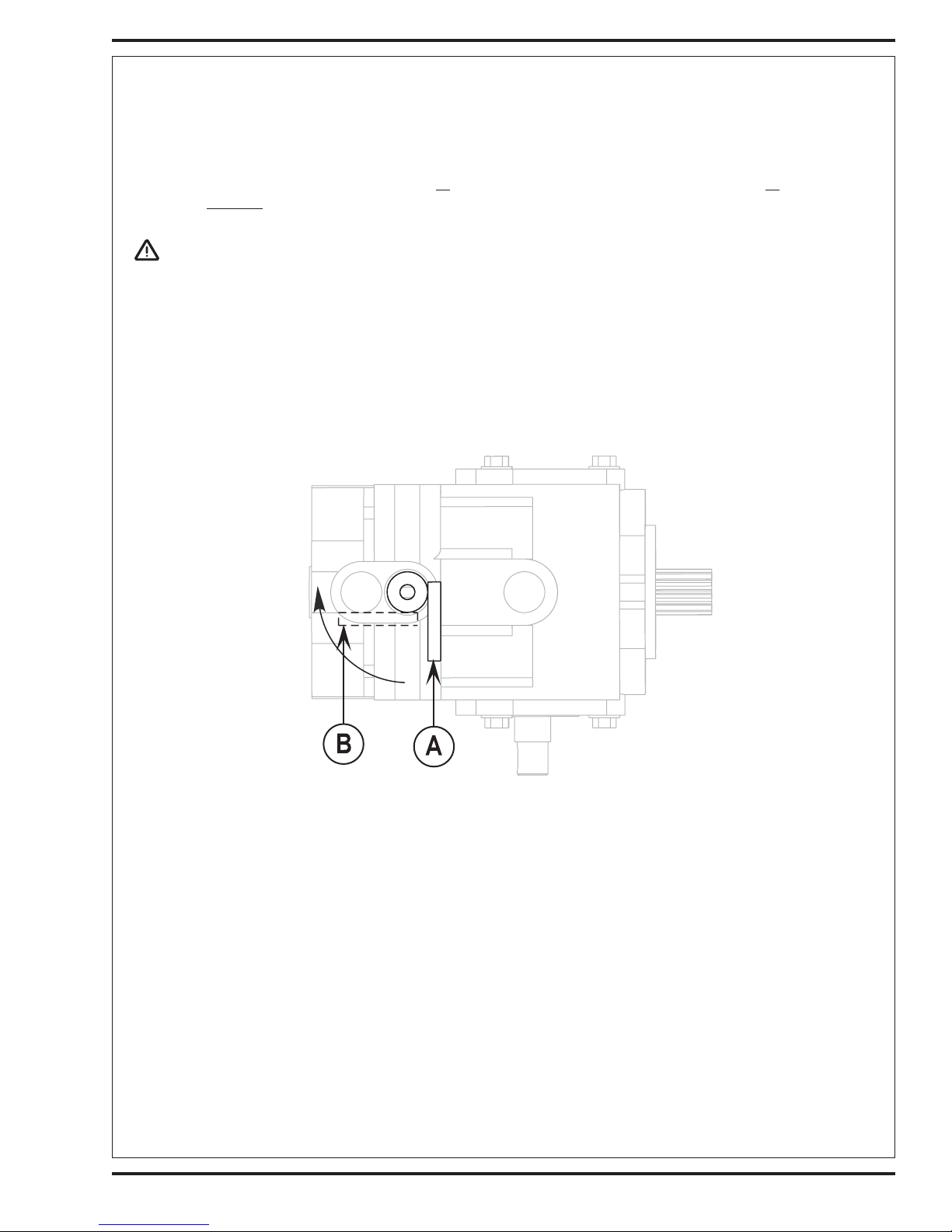
TOWING OR PUSHING A DISABLED MACHINE
The machine’s drive propelling pump is manufactured with a tow valve. This valve prevents damage to the hydraulic system when the machine
is being towed/pushed short distances without use of the engine.
To access the valve, open the Engine Compartment Door (
as shown on the underside of the hydrostatic pump by reaching under the radiator. Turn the valve 90 degrees, this disengages the hydrostatic
lock between the motor and pump.
22) and lift off the Right Engine Compartment Access Panel (37). Locate the valve
CAUTION!
The hydraulic propelling pump can be damaged if the machine is towed with the valve in the normal working position (A).
Reference the illustrations below for the normal working setting (A) (vertical) and the free wheeling towing setting (B) (horizontal). Note: If the tow
valve is left in free wheeling (B) (horizontal) position the propelling pump can’t drive the machine FWD or REV. No damage will result, just re-set
valve to the normal working setting (A) (vertical). NOTE: Tow or push machine no faster than a normal walking pace (2-3 mph - 3-5 km/h) and
for short distances only. If the machine is to be moved long distances the drive wheel needs to be raised off the floor and placed on a suitable transport
dolly.
BOTTOM VIEW OF HYDROSTATIC PUMP
OTHER MANUALS AVAILABLE
The following manuals are available from the Nilfisk-Advance Literature Service Department, for your Rider Scrubber/Sweeper:
• Parts List - Form Numbers 56042440 (all systems except hydraulic)
• Operation Manual - Form Numbers 56041546 (Danish, Norwegian, Swedish, Finnish)
• Quick Start Service Manual 56043093
• Engine Manuals
1.6L Industrial Engine Operator Manual (excerpt from 16LECSS) 56041564
1.6L Industrial Engine Service Manual 36100009*
1.6L Emission Certified Industrial Engine Emission Control System Service Manual 16LECSS*
*Available in electronic format only
56042445 (hydraulic system)
56041547 (German, French, Dutch, Russian)
56041548 (Spanish, Portuguese, Italian, Greek)
56041578 (Estonian, Latvian, Lithuanian, Slovenian)
56041579 (Slovakian, Czech, Polish, Hungarian)
56041580 (English)
FORM NO. 56043094 / Captor™ 4300, 4800, 5400 / CR 1100, 1200, 1400 - 3

CAUTIONS AND WARNINGS
SYMBOLS
Nilfisk-Advance uses the symbols below to signal potentially dangerous conditions. Always read this information carefully and
take the necessary steps to protect personnel and property.
DANGER!
Is used to warn of immediate hazards that will cause severe personal injury or death.
WARNING!
Is used to call attention to a situation that could cause severe personal injury.
CAUTION!
Is used to call attention to a situation that could cause minor personal injury or damage to the machine or other property.
GENERAL SAFETY INSTRUCTIONS
Specific Cautions and Warnings are included to warn you of potential danger of machine damage or bodily harm.
DANGER!
• This machine emits exhaust gases (carbon monoxide) that can cause serious injury or death, always provide adequate
ventilation when operating this machine.
WARNING!
• This machine shall be used only by properly trained and authorized persons.
• While on ramps or inclines, avoid sudden stops when loaded. Avoid abrupt sharp turns. Use low speed down hills. Clean
only while ascending (driving up) the ramp.
• Keep sparks, flame and smoking materials away from the battery and fuel system.
• Remove all jewelry when working near electrical components.
• Take precautions to prevent hair, jewelry, or loose clothing from becoming caught in moving parts.
• Turn the key switch off (O), disconnect the battery, and set the parking brake before servicing the machine.
• Never work under a machine without safety blocks or stands to support the machine.
• Do not dispense flammable cleaning agents, operate the machine on or near these agents, or operate in areas where
flammable liquids exist.
• Do not clean this machine with a pressure washer.
• Keep the LP tank Service Valve closed when the tank is not in use.
CAUTION!
• This machine is not approved for use on public paths or roads.
• This machine is not suitable for picking up hazardous dust.
• When operating this machine, ensure that third parties, particularly children, are not endangered.
• Before performing any service function carefully read all instructions pertaining to that function.
• Do not leave the machine unattended without first turning the key switch off (O), removing the key and applying the parking
brake.
• Turn the key switch off (O) before changing the brushes, and before opening any access panels.
• Use caution when moving this machine in below freezing temperature conditions. Any water in the solution or recovery
tanks or in the hose lines could freeze, causing damage to valves and fittings. Flush with windshield washer fluid.
• The battery must be removed from the machine before the machine is scrapped. The disposal of the battery should be
safely done in accordance with your local environmental regulations.
SAVE THESE INSTRUCTIONS
4 - FORM NO. 56043094 / Captor™ 4300, 4800, 5400 / CR 1100, 1200, 1400
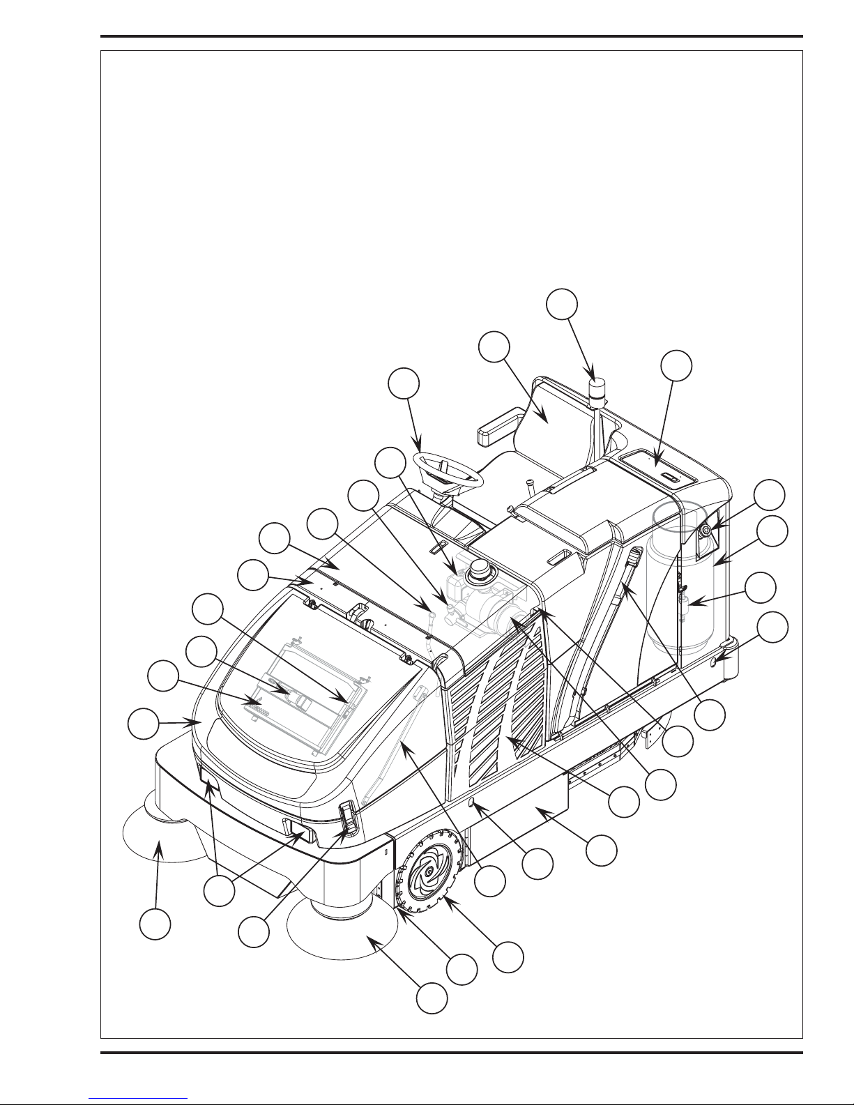
KNOW YOUR MACHINE
1 Operator’s Seat
2 Strobe Light (optional)
3 Solution Tank Fill
4 Gasoline Tank Cap
5 Fuel Tank
6 Tie Down Locations
7 Recovery Tank Drain Hose
8 Engine Air Filter
9 Left Engine Compartment Access Panel
10 Main Broom Left Access Door
46
11 Battery
12 Hopper Lid Prop Rod
13 Front Wheel
14 Left Side Broom
15 Hopper Lid Latch
16 Headlights
17 Right Side Broom
18 Hopper Cover
19 Dust Control Filter
20 Dust Control Shaker Assembly
2
1
3
24
23
4
18
19
17
21
20
16
49
15
22
45
5
47
6
7
48
8
9
10
6
12
44
13
14
FORM NO. 56043094 / Captor™ 4300, 4800, 5400 / CR 1100, 1200, 1400 - 5
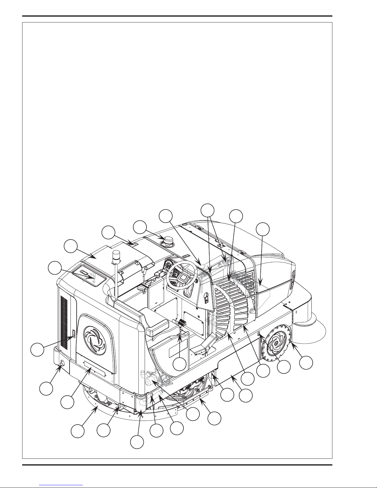
KNOW YOUR MACHINE
21 Shaker Assembly Latch
22 Engine Compartment Door
23 Coolant Recovery Tank
24 Steering Wheel
25 Squeegee Handle
26 Squeegee Tool Assembly
27 Tail Light
28 Exhaust Tail Pipe
29 Fuel Tank Compartment Door
30 Recovery Tank Lid
31 Recovery Tank “Tip-Out” Grip
32 Engine Air Filter Hood
33 Radiator Cap
34 Oil Cooler “Tip-Out” Latches
35 Hydraulic “Charge” Oil Filter
33
36 Hydraulic Reservoir / In Tank Return Oil Filter
37 Right Engine Compartment Access Panel
38 Main Broom Right Access Door
39 Access Door Latch
40 Skirt Assembly
41 Inline Solution Filter
42 Solution Tank Drain Hose
43 Rear Roller Bumper
44 Jacking Location
45 Engine Oil Dipstick
46 Air Filter Service Indicator
47 Fuel Filter (Gas Models)
48 Recovery Tank Latch
49 Hydraulic Reservoir Access Panel
50 Water Level Gauge
51 Operator Seat Adjustment Lever
34
35
29
28
50
30
27
31
32
51
39
11
38
36
37
6
44
26
6 - FORM NO. 56043094 / Captor™ 4300, 4800, 5400 / CR 1100, 1200, 1400
25
43
41
42
6
40
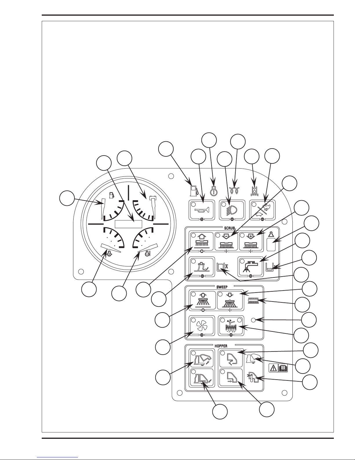
OPERATOR'S COMPARTMENT
A Low Fuel Indicator (LP)
B Horn Switch
* Horn ON Indicator
C Engine Service Indicator (triggered by ECU)
D Headlight Switch
* Headlight ON Indicator
E Glow Plug Indicator (Diesel / Release key after indicator turns OFF)
F Hydraulic Filter Plugged Indicator
G Engine Speed Switch
* Engine Speed Switch Indicator
H Scrub Pressure Decrease Switch
* Scrub Pressure Decrease Indicator
A
B
DD
OIL
PSI/BAR
PP
E
100
EE
-
+
HOURS 1/10
120
18
13
10
VOLTSFUEL
TEMP
F/C
250
100
175
75
50
F
1/2
8
50
3
1
0
I Scrub Pressure Increase Switch
* Scrub Pressure Increase Indicator
J Scrub Pressure Display
K Solution Switch
* Solution System Indicator
L Solution Tank Empty Indicator
M Recovery Tank Full Indicator
N Side Broom DOWN/ON Switch
* Side Broom ON Indicator
O Main Broom ON Indicator
C
D
E
F
G
H
I
J
K
L
CC
BB
AA
Z
Y
X
W
V
M
N
O
P
Q
R
S
T
U
FORM NO. 56043094 / Captor™ 4300, 4800, 5400 / CR 1100, 1200, 1400 - 7
OPERATOR'S COMPARTMENT
P Light Sensor
Q Shaker Switch
* Shaker Indicator (left)
* Dust Filter Plugged Indicator (right)
R Open Dump Door Switch
* Open Dump Door Indicator
S Hopper Open Indicator
T Hopper Overtemp Indicator
U Close Dump Door Switch
* Close Dump Door Indicator
V Lower Hopper Switch
* Lower Hopper Indicator
W Raise Hopper Switch
* Raise Hopper Indicator
X Dust Control Switch
* Dust Control ON Indicator
Y Side Broom UP/OFF Switch
* Side Broom OFF Indicator
Z Vacuum System Switch
* Vacuum System Indicator
JJ
II
HH
KK
AA Scrub System OFF Switch
* Scrub System OFF Indicator
BB Coolant Temperature Gauge
CC Oil Pressure Gauge
DD Fuel Gauge (Gas / Diesel)
EE Voltmeter
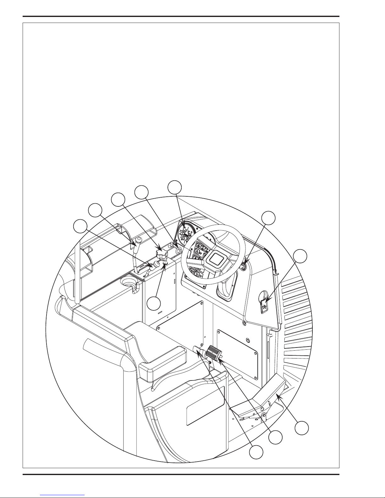
FF Brake Pedal
GG Parking Brake Latch
HH Solution Flow Control Lever
II Main Broom Raise/Lower (ON/OFF) Lever
JJ Main Broom Adjust Knob
KK Hopper Safety Support Lever
LL Control Panel
MM Ignition Switch
NN Tilt Wheel Lever
O O Drive Pedal
PP Hour meter
QQ Main Broom Overload Indicator Light
LL
MM
QQ
NN
OO
FF
8 - FORM NO. 56043094 / Captor™ 4300, 4800, 5400 / CR 1100, 1200, 1400
GG
STEERING SYSTEM
FRON T
C
B
A
D
E
Steering Column
Hydraulic Steering Unit
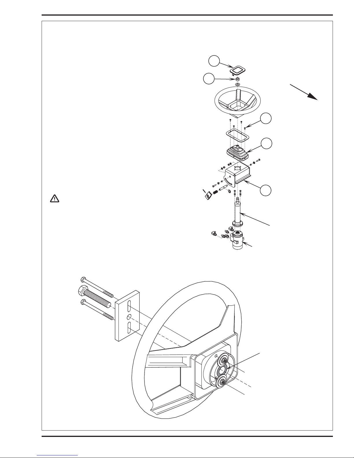
STEERING WHEEL REMOVAL
1 See Figure 1. Pry up steering wheel Cap (A).
2 Remove center hex Nut (B). Note: This is a metric nut, you will need
a 24mm socket.
3 Use a steering wheel puller to remove steering wheel from splined
shaft. NOTE: It may be necessary to enlarge holes in steering wheel,
also be sure to support the metal splined bushing in the center of the
steering wheel (see Figure 2) when pulling the wheel.
HYDRAULIC STEERING UNIT REMOVAL
1 Follow steps 1-3 in the Steering Wheel Removal section.
2 Remove the (5) screws that secure the bottom console panel (location
operator’s compartment below steering wheel).
3 See Figure 1. Remove the (4) item (C) Screws and pull off the rubber
Steering Boot (D).
4 Remove the (4) hex screws (10mm) that secure the hydraulic steering
unit to its Mounting Bracket (E).
5 Adjust the tilt steering to help in removing the steer unit and separate
the column. Note: Grip steering column and pull down on steer unit
to easily separate.
6 Remove the (5) hydraulic hoses to complete removal of steering unit.
CAUTION!
There will be oil in the motor and hoses, be prepared to plug and
cap system connections.
FIGURE 1
FIGURE 2
Splined
Bushing
FORM NO. 56043094 / Captor™ 4300, 4800, 5400 / CR 1100, 1200, 1400 - 9

STEERING SYSTEM
HYDRAULIC STEERING CYLINDER REMOVAL
1 Remove the recovery tank assembly from the machine.
2 Follow steps in the Solution Tank Removal section.
3 Remove the (2) screws that secure the electrical relay mount assembly and pull it out from the control box compartment.
4 See Figure 3. Remove the Hairpin (F) and then slide out the cylinder Mount Pin (G).
5 Remove the cylinder hoses, then plug and cap to prevent oil lose and system contamination.
6 Mark the steering rack and spur gear location with a center punch to help when reassembling.
7 Lift the rack and cylinder assembly straight up to complete its removal from the chassis.
8 With the rack and cylinder assembly removed inspect the nylon wear plates. Replace when mounting screws are exposed and striking the
rack.
WEAR ADJUSTMENT FOR CYLINDER RACK
1 See Figure 3. Loosen the (2) Hex HD Screws (H). Then using a large flat bladed screwdriver pry between the Adjustment Bracket (I) and
the steer spindle. This will remove any excessive play in the nylon wear plate and the rack, then tighten bracket-mounting screws to secure.
STEERING SPINDLE ASSEMBLY REMOVAL
1 Remove the squeegee tool assembly from the machine then remove the ignition key, set the parking brake and block the front wheels.
2 Remove the solution tank assembly (see Solution Tank Removal section for instructions).
3 See Figure 3. Remove the (2) (H) Hex Screws that fasten the rack adjustment Bracket (I) then rotate the bracket to clear the spur gear and
remove.
4 Remove from the spindle shaft the Cotter Pin (J) and Castle Nut (K). Next remove the (2) Set Screws (L) using a 4mm hex key wrench.
5 Pull the spur gear from its shaft then remove the square shaft Key (M) and Gear Spacer (N). Note: The gear spacer bevel faces down to
reassemble.
WARNING!
Never work under a machine without safety blocks and stands to support machine.
6 Jack up the rear of the machine approximately 24 inches (60cm) and put the jack stands in place under rear corner supports. Note: Guide
the spindle and wheel assembly out from under its frame housing being careful not to damage shaft threads and bearing surfaces.
7 Important Service Tip: Observe the hydraulic wheel motor hoses their routing and correct fitting locations then disconnect the (3) hoses, (2)
P-clamps (plug and cap hoses and fittings).
8 Service Tip: When installing or removing the spindle wheel assembly, use a piece of cardboard underneath the wheel to help in sliding the
assembly around (positioning).
BEARING REPLACEMENT AND SPINDLE INSTALLATION
1 You now have access to the upper and lower bearing cones, cups and seals (O, P & Q). Note: If replacing or inspecting bearings be sure
to (re) pack bearings with white lithium grease before installing.
2 To reassemble, first install the lower bearing cup, cone and seal into the Steering Casting (R). Note: It is important that the shaft goes through
the lower bearing as straight as possible, it may be easier to install the spindle with the tire removed placing the spindle weldment on top of
a movable service jack.
3 Slowly lower the rear of the machine guiding and repositioning the shaft through the center of the housing until the drive wheel supports the
machine.
4 Install the upper bearing cup, cone, seal, spacer and spur gear.
5 Install and tighten the castle nut, torque to 40 ft/lbs. (54Nm). Then loosen nut to align cotter pin.
6 Follow the spindle removal steps 1-4 in reverse order. Check that the drive wheel is positioned straight ahead, align the rack and gear (marked
teeth). Next follow the adjustment instructions for the cylinder rack and spur gear clearance (fit up) to eliminate any sloppy steering operation.
10 - FORM NO. 56043094 / Captor™ 4300, 4800, 5400 / CR 1100, 1200, 1400
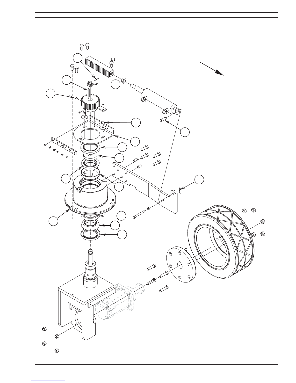
FIGURE 3
STEERING SYSTEM
J
FRONT
M
L
O
K
H
G
I
Q
N
F
P
P
R
O
Q
FORM NO. 56043094 / Captor™ 4300, 4800, 5400 / CR 1100, 1200, 1400 - 11
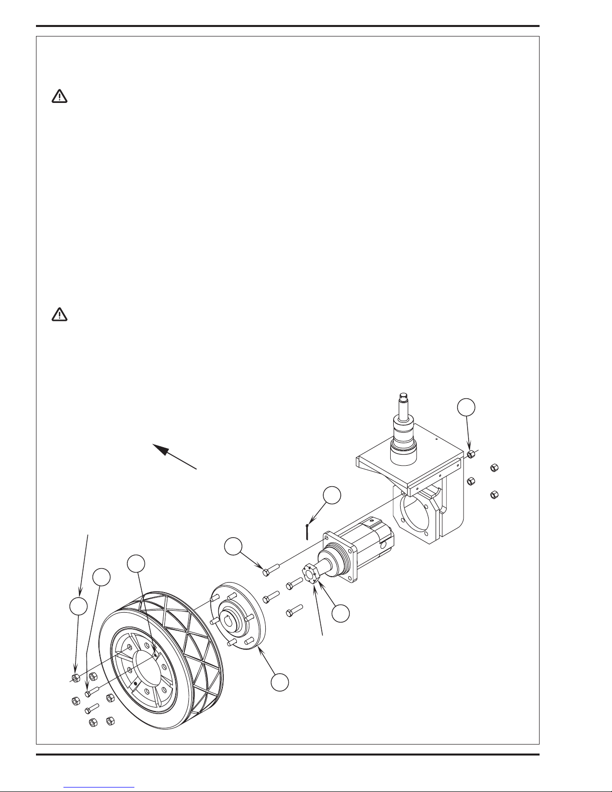
WHEEL DRIVE SYSTEM
DRIVE TIRE REMOV AL
WARNING!
Never work under a machine without safety block or stands to support machine.
Disconnect battery before servicing.
1 Turn steering wheel to the right full lock position and also remove the squeegee tool.
2 Turn off engine, set parking brake and block front wheels.
3 See Figure 1. Remove the (6) Wheel Lug Nuts (A) (use a 21mm socket). Installation torque is100 ft/lbs. (135 N/M).
4 If removing drive motor, remove the Cotter Pin (B) and loosen the motor shaft Castle Nut (C). Note: You will need a 1-7/16 inch socket for
castle nut (see torque notes Figure 1).
5 Thread (2) 1/2-13 x 2" threaded to HD Pusher Bolts (D) into the (E) Tire Hubs threaded holes.
6 Jack up machine until wheel clears the floor and place jack stands under machine.
7 Turn (thread) in equally both bolts to separate the tire assembly from the wheel motor Drive Hub (F).
WHEEL DRIVE MOTOR REMOVAL
1 Follow steps 1-7 in Drive Tire Removal section.
2 Remove the drive motor shaft castle nut.
3 Mark and remove the three hydraulic hoses at the motor.
CAUTION!
There will be oil in the hoses and motor, be prepared to plug hoses and cap motor fittings.
4 Remove the (4) Hex Screws (G) and Nuts (H) and remove the motor from the spindle weldment. Use a puller to remove the drive hub assembly
from the tapered motor shaft and reuse (salvage).
5 Reassemble in reverse order (see torque notes Figure 1). Operate the machine and check for leaks and proper performance.
FIGURE 1
H
FRONT
B
Torque to
100 ft./lbs. (135 Nm).
G
E
D
A
C
12 - FORM NO. 56043094 / Captor™ 4300, 4800, 5400 / CR 1100, 1200, 1400
Torque to 375 ft./lbs. (508 Nm) dry
or 475 ft./lbs. (644 Nm) lubed,
then tighten to align cotter pin.
F
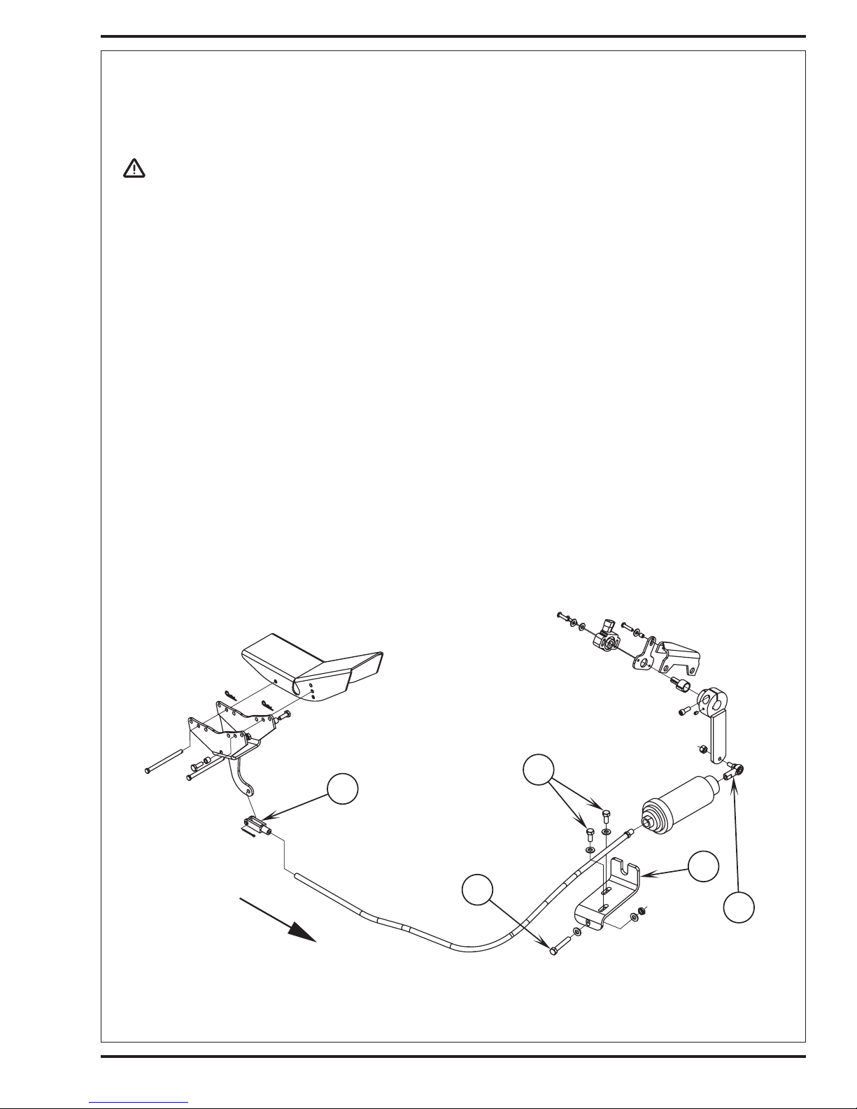
WHEEL DRIVE SYSTEM
HYDROBACK DRIVE PEDAL NEUTRAL ADJUSTMENT
When servicing the hydrostatic drive system, always check for any machine creeping (movement) in the neutral position. The machine must not
move in either Fwd or Rev after the drive pedal is released. If machine creeping is experienced the neutral position of the hydro back must be adjusted.
WARNING!
Use jack stands to support the machine when setting the neutral drive pedal adjustment.
1 Block the front wheels. Jack up machine until the rear drive wheel is off the floor. Place supports at the rear corners of the machine.
2 Remove the right side engine cover to access the hydroback adjustment bracket.
3 See Figure 2. Loosen the two Lock Screws (I) that secure the moveable cable mount Bracket (J) to the chassis.
4 Start the engine and observe the direction of the drive wheel rotation. Next turn the adjustment Screw (K) clockwise (CW) or counterclockwise
(CCW) to move the cable mounting bracket (in or out) enough to stop any wheel movement. The pump arm is now in neutral, tighten the two
lock screws to secure the neutral pump arm setting.
5 Test the neutral adjustment by activating the drive pedal in both FWD & REV to confirm proper wheel motor control. Readjust again if neutral
setting is not repeatable. Replace the hydroback and or its linkage if a neutral adjustment can not be obtained.
6 Turn the engine off then check to see that it will restart. If engine will not start the pedal sense switch is probably out of its neutral (dead band)
setting and needs to be reprogrammed. See the sense switch replacement manual section for programming instructions.
HYDROBACK CABLE ASSEMBLY REMOVAL
1 Disconnect at both cable ends (foot pedal and pump arm) the Clevis (L) and Rod End (M).
2 Loosen both cable anchor connector nuts.
3 Slide hydroback assembly from its chassis and cable adjustment mounting brackets.
4 After installing a new cable/hydroback see the hydroback pedal neutral adjustment instructions.
FRONT
FIGURE 2
I
L
J
K
M
FORM NO. 56043094 / Captor™ 4300, 4800, 5400 / CR 1100, 1200, 1400 - 13

FRONT WHEEL SYSTEM
FRONT WHEEL REMOVAL AND BRAKE INSPECTION
1 Raise hopper and engage safety support.
2 Open broom-housing door (LH or RT) and remove the top gasket seal (so not to damage). Place jack towards front of housing and jack on
machine frame to where the front wheel clears the floor.
3 Place safety blocking under the front frame member to support.
4 Remove the Wheel Screw (A) then work the tire off of wheel spindle. Note: the parking brake must be released to allow wheel to be removed.
Also tap on the backside of wheel with wood blocking to help loosen a stubborn stuck wheel.
5 Inspect the spindle; wheel bearings and brake shoe linings for abnormal wear and replace all worn parts. A new brake shoe lining thickness
will measure 11/64 (.172) inches or 4.4 mm.
6 Check for approximately one inch (25mm) of operator brake pedal free-play (see instructions below to adjust) and test drive machine for proper
operation.
FRONT BRAKE SHOE ADJUSTMENT
1 Raise hopper and engage safety support.
2 See Figure 1. Remove the (6) Philips Screws (B) then pull the broom Housing Skirt (C) to the side to access the brake cable clevis.
3 See Figure 1 detail of clevis adjustment, length or shorten its threaded end to obtain the correct brake pedal free play. Note both brakes (LH
& RT) need to be adjusted equally.
4 If the brake cable clevis adjustment does not eliminate excessive pedal travel (poor braking performance) check for worn out brake shoes
and a stretched brake cable. The ends of the brake cable at the wheels have adjustable threaded cable anchor fittings. Shorten the length
of cable wire extending out of the cable casing by adjusting the cable anchor fittings at the wheel casting pocket (inset).
BRAKE CABLE REPLACEMENT
1 Follow the scrub deck removal instruction in the scrub system manual section. The removal of the deck is necessary to access the brake pedal
cable guide pulley and cable anchor points (location middle of machine under operator floor plate).
2 See the brake shoe adjustment instructions above to remove the brake cable ends at the wheels.
14 - FORM NO. 56043094 / Captor™ 4300, 4800, 5400 / CR 1100, 1200, 1400
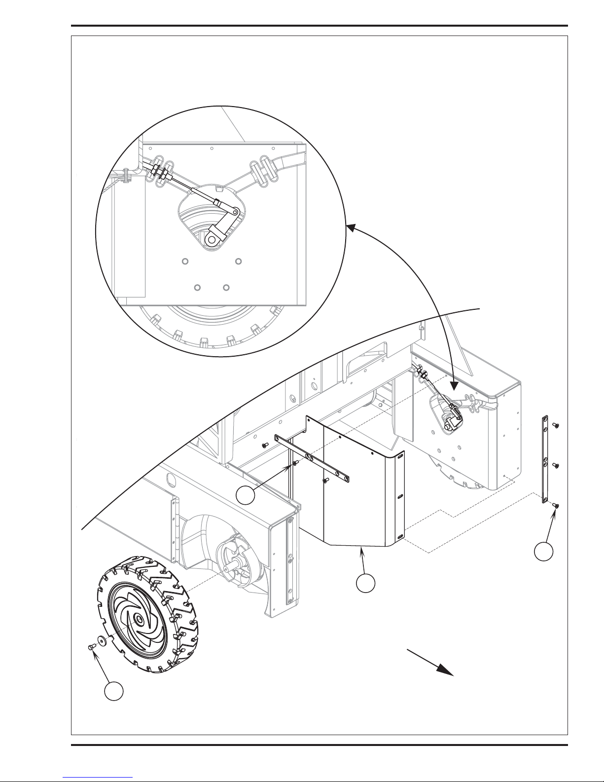
FRONT WHEEL SYSTEM
FIGURE 1
A
B
B
C
FRONT
FORM NO. 56043094 / Captor™ 4300, 4800, 5400 / CR 1100, 1200, 1400 - 15
 Loading...