

Page 1
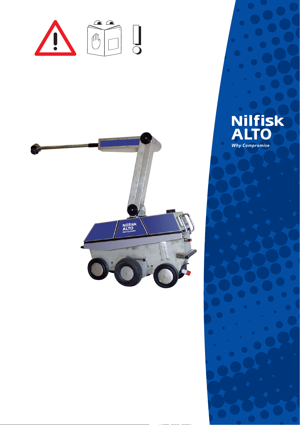
MULTICLEANER 7-53
User Manual
107309941
Page 2

Page 3

MULTICLEANER 7-53
Index
1 Introduction ..................................................................................5
1.1 Preface ..................................................................................5
2 Important information ..................................................................................5
2.1 Warranty conditions ................................................................5
2.2 Safety ..................................................................................5
3 Application/operation ..................................................................................6
3.1 Safety ..................................................................................6
3.1.1 Warning sign on the door ..........................................7
3.1.2 Access to robot during operation...............................7
3.1.3 Training of staff ..........................................................7
4 Service ..................................................................................7
4.1 Safety ..................................................................................7
5 Description of plant ..................................................................................8
5.1 Operating principle .................................................................8
5.2 Field of application .................................................................8
5.3 Automatic washing .................................................................9
5.4 Mechanics ............................................................................10
5.4.1 Tyres ........................................................................10
5.4.2 Nozzle .....................................................................10
5.4.3 Materials ..................................................................10
5.4.4 Ultrasonic sensors ...................................................10
5.5 Components in the water supply ..........................................10
5.5.1 Water filter ...............................................................10
5.5.2 Water valve .............................................................10
5.5.3 Flow switch ..............................................................10
5.6 Control ................................................................................11
5.7 Cable reel .............................................................................11
5.7.1 Cable type ............................................................... 11
5.7.2 Cable strain relief ....................................................11
5.8 Motor pump unit/compressor................................................11
5.9 Motors/gear .......................................................................... 11
5.9.1 Types ....................................................................... 11
5.10 Safety device ........................................................................12
5.10.1 Emergency switch ...................................................12
6 Requirements for the existing
installation/ inventory ................................................................................12
6.1 Power supply ........................................................................12
6.2 Water ................................................................................12
6.3 Running sands filter .............................................................12
6.4 Hose dimension / quality ......................................................12
6.5 Ambient temperature - operation / storage ..........................13
6.6 Inventory in inspection gallery ..............................................13
6.7 Floor finish in inspection gallery ...........................................13
6.8 The pens ..............................................................................13
7 Servicing ................................................................................14
7.1 Safety during the application of the
MULTICLEANER ..................................................................14
Original Instructions
3
Page 4

MULTICLEANER 7-53
7.2 Installation ............................................................................15
7.2.1 Frost in the MULTICLEANER ..................................15
7.2.2 Placement of robot in inspection gallery..................15
7.2.3 Laying/connection of water hose .............................15
7.2.4 Fixing of cable in inspection gallery.........................15
7.2.5 Adjustment of washing arm .....................................16
7.2.6 Engagement of propulsion wheels ..........................16
7.3 Menu ................................................................................16
7.4 Cleaning of robot ..................................................................18
7.4.1 General ....................................................................18
7.5 Storage ................................................................................18
7.5.1 Frost protection .......................................................18
7.6 Transport ..............................................................................18
7.6.1 Trailer ......................................................................18
7.6.2 Application of ramps/winches ..................................18
7.6.3 Fastening during transport ......................................18
8 Operation ................................................................................19
8.1 Indicator lamp .......................................................................19
9 Maintenance ................................................................................19
9.1 General ................................................................................19
9.2 Maintenance procedures ......................................................19
9.2.1 Service interval of motor/pump unit according
to Nilfisk-ALTO ........................................................19
9.2.2 Oil change ...............................................................20
9.2.3 Inspection of long distance nozzle ..........................20
9.2.4 Cleaning of filter in dirt collector ..............................20
9.2.5 Inspection of pressure in tyres ................................20
9.2.6 Banjo bolt at the nozzle head ..................................20
9.2.7 Lubrication ...............................................................20
9.2.8 Inspection of initial tension of the springs in
the cable reel ...........................................................20
10 Service ................................................................................21
10.1 Service visit ..........................................................................21
10.2 Trouble shooting/correction ..................................................21
10.2.1 Error list ...................................................................21
10.2.2 Other malfunctions ..................................................22
11 Specifications ................................................................................23
11.1 Robot and motor/pump unit ..................................................23
12 EU Declaration of Conformity ................................................................................23
4
Original Instructions
Page 5
1 Introduction
1.1 Preface We congratulate you on your new MULTICLEANER.
To get the most out of your new MULTICLEANER it is important that
you read the user manual carefully through and follow the advice
given about safety, operation and maintenance.
This safety and warning symbol indicates that the section concerned contains important safety rules and recommendations to
prevent accidents.
Important
MULTICLEANER 7-53
Safety
We reserve the right to alter the specifications.
2 Important information
2.1 Warranty conditions Concerning warranty our general sales and delivery conditions
apply.
We reserve the right to further technical developments.
2.2 Safety CAREFULLY READ THROUGH THIS USER MANUAL BEFORE
STARTING TO USE THE ROBOT !
Original Instructions
5
Page 6
MULTICLEANER 7-53
3 Application/operation
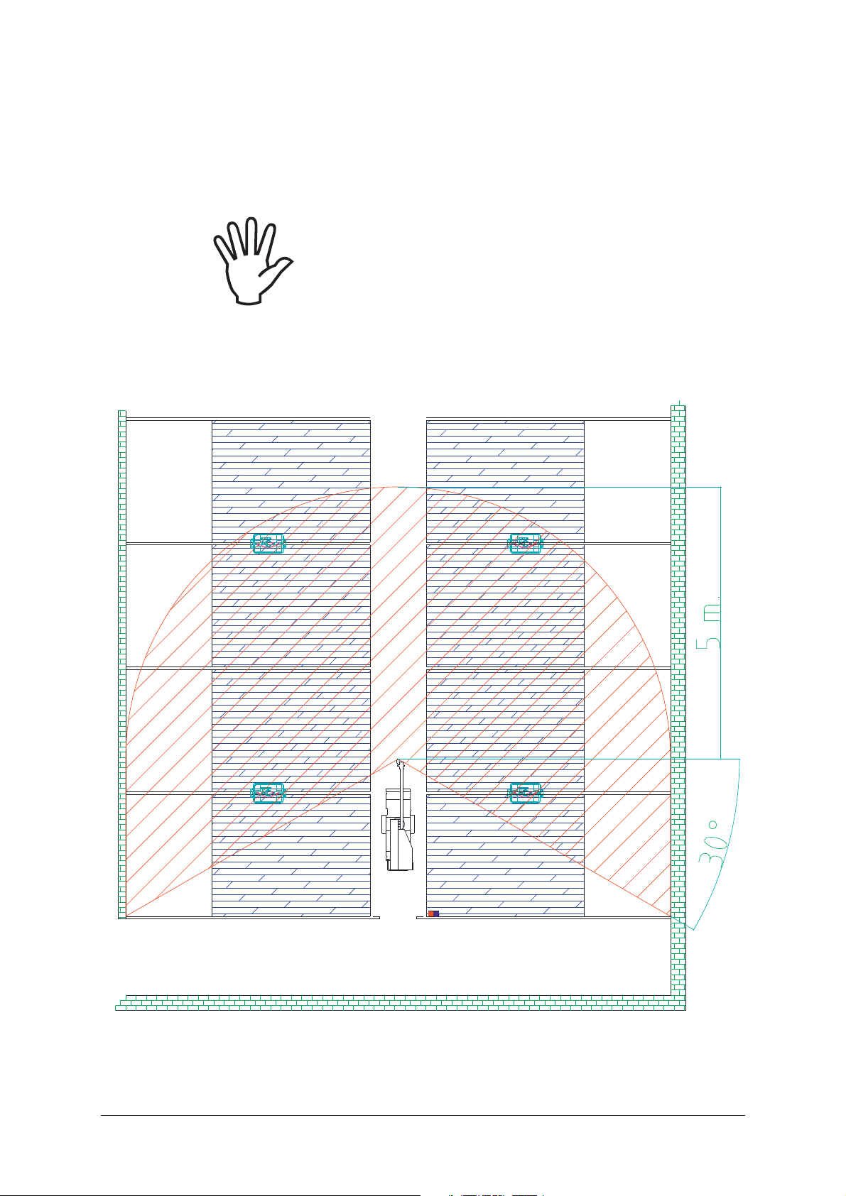
3.1 Safety When the washing robot is in operation all shieldings must be
in place. During automatic washing no persons must stay in the
washing field of the robot (hatching). See illustration below.
Only persons who have been specially instructed must stay in the
pig house section where the robot is working.
6
Original Instructions
Page 7

MULTICLEANER 7-53
3.1.1 Warning sign on the
door
3.1.2 Access to robot during
operation
3.1.3 Training of staff Employees who are to operate the robot will beyond the written in-
The accompanying warning sign must be placed on the door leading to the pig house section where the automatic washing is taking
place. The sign must be visible to any person who may have access
to the pig house section.
If the sign is lost or if there is more than one access, a new sign can
be ordered from Nilfisk-ALTO. Order no. 107307061.
The robot must be placed so that the operator has always got access to the display and the control knobs without having to pass
the robot during the automatic washing, meaning that the end of
the robot where the display is placed must turn to the access side
during operation.
structions always receive a verbal instruction from a staff member of
Nilfisk-ALTO in connection with the delivery and starting up of a new
robot.
4 Service
4.1 Safety Always disconnect the electrical plug from the socket prior to
service, maintenance, repair or other works on the washing robot.
Repairs to the control pen of stainless steel must be carried out by
an electrician as it contains automatic fuses, contactor, emergency
stop module and power supplies.
The control pen of plastic contains the control system and must only
be serviced by a Nilfisk-ALTO service technician.
When working underneath the robot you should be very careful as it
weighs 285 kg.
Original Instructions
7
Page 8

MULTICLEANER 7-53
5 Description of plant
5.1 Operating principle The MULTICLEANER is used for the cleaning of pig houses. It takes
over most of the heavy, trivial and time consuming manual cleaning
job. Using the robot the manual high pressure washing is reduced
by up to 80%. The remaining 20% high pressure washing is quickly
done because of the long soaking time of the impurities.
The control of the robot is automatic when the user has made a few
choices on the display.
The washing sequency of the MULTICLEANER is programmed by
the user before each cleaning. The user may adapt the washing
sequency to achieve an optimum cleaning of the actual pig house
section.
Distance and course of the MULTICLEANER is controlled by two
ultrasonic sensors, which "feel" against the inventory in the aisle.
The washing arm consists of a vertical tower and a horizontal arm.
The tower is mounted on a turntable on the chassis, which can rotate 90 degrees sideways proportional to the direction of movement.
At the top of the tower the horizontal arm is mounted in a swivel.
The tower and the arm can be locked in fixed positions in proportion
to each other.
At the end of the horizontal arm the high pressure nozzle is mounted on a spindle stretching through the horizontal arm. The nozzle
can rotate 360 degrees. The outermost part of the horizontal arm
can rotate around its own spindle, and the angle of the water jet can
be turned +/- 90 degrees in proportion to vertical position.
The high pressure nozzle turns like a fan forwards and backwards
within a limited angle. The speed of the nozzle is variable, thus minimising the water consumption.
In order that the nozzle is washing at an optimum, it is important
that the tower and the arm are adjusted so that the nozzle head is
placed in the middle of the aisle and so close to the inventory and
the floor as possible.
It is the responsibility of the user that the arm is adjusted so that it
will not bump into the inventory of the pig house.
Stop-lists on front and rear bumper signal to the control unit in case
of bumping assuming that the MULTICLEANER has reached the
opposite end of the aisle, and the direction of movement will be
changed and the next step of the washing sequence will be started.
5.2 Field of application The MULTICLEANER is mainly intended for use in pig fattening
houses, climate-controlled livestock buildings and farrowing houses.
To optimise the washing result and minimise the water consumption,
it will be an advantage to use a dustbinding or a soaking system to
soak the pig house before using the MULTICLEANER. However, this
is not required.
8
Original Instructions
Page 9
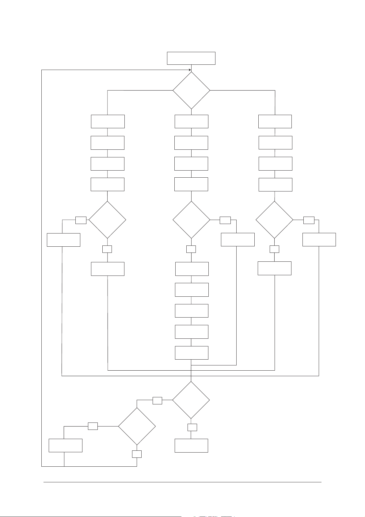
5.3 Automatic washing
MULTICLEANER 7-53
Start washing
Side?
Aisle washing
Yes
Left
Left
endwall
Wash left
forwards
Left
endwall
Aisle washing ?
(only 1st wash)
No
Wash left
backwards
Both
Right
endwall
Wash right
forwards
Right
endwall
Aisle washing ?
(only 1st wash)
No
Wash right
backwards
Left
endwall
Yes
Aisle washing
Right
Right
endwall
Wash right
forwards
Right
endwall
Aisle washing ?
(only 1st wash)
No
Wash right
backwards
Yes
Aisle washing
Pausing
Yes
Pause ?
No
No
Wash left
forwards
Left
endwall
Wash left
backwards
Final
washing ?
Yes
Wash finished
Original Instructions
9
Page 10

MULTICLEANER 7-53
5.4 Mechanics
5.4.1 Tyres
5.4.2 Nozzle Special corrosion-resistant long distance pencil jet nozzle with 1/4"
5.4.3 Materials The MULTICLEANER is mainly produced of corrosion-resistant,
5.4.4 Ultrasonic sensors The MULTICLEANER features two ultrasonic sensors on the right
The driving wheels are fitted with rubber tyres in the size 4.00 x 6
on rims made in one piece with the toothed wheel in a synthetic
material.
Stand wheels are solid rubber tyres on synthetic rims.
pipe thread and 14 mm hexagon. The nozzle opening is 1.5 mm.
synthetic and rubber materials.
In a few cases it has not been possible to produce or require parts
made of above-mentioned materials. Instead we have chosen other
but also very durable parts to diminish wear and corrosion.
These materials have been chosen to protect the robot from the
extremely tough environment (water and ammoniac fumes) in which
it has to work and thus to avoid increased risk of stoppage because
of corrosion, unnecessary wear etc.
side of the robot, which are used for regulation of direction and
distance.
The sensors emit/pick up sound impulses and the controller then
calculates the distance to the inventory in the aisle. It measures the
time from the emission of the sound impulse till the pick up of the
echo.
This information is then converted to a real distance.
If an echo has not been picked up within a short time because of
missing inventory sides, the control will activate the alarm.
If the ultrasonic sensors are covered by a lot of dirt, the reliability
may be affected. Note! Check that the two ultrasonic sensors are
clean before starting the robot and that the gates into the individual
pens are closed.
5.5 Components in the
water supply
5.5.1 Water filter
5.5.2 Water valve On the water inlet side a 24 VDC, solenoid valve is mounted. This
Before the water valve there is a water filter with a rustproof strainer
with a mesh size of 0.25 mm, which strains impurities out before
they reach the water valve. The water filter should be cleaned/
checked each 100 operating hours.
valve is open or closed depending on the working phase of the machine. The function of the valve is to disconnect the water supply
when the arm turns or the robot is in stand-by mode.
The valve is closed when the there is no voltage to the coil.
5.5.3 Flow switch In extension of the water valve a flow switch is mounted, which
continually checks the water supply. In case the water supply fails, if
for instance the water hose comes off, a signal is transmitted to the
control, which shuts down the MULTICLEANER and activates the
alarm. Thus it is avoided that the pump unit breaks down. The flow
switch has been adjusted from the factory.
10
Original Instructions
Page 11

MULTICLEANER 7-53
5.6 Control The control is mainly built up of a control card with related module
based add-on cards.
5.7 Cable reel
The robot features a built-in automatic cable reel unwinding/winding
up the power cable during operation and keeping it tight all the time
dependent on the direction of travel, and running over of the cable is
avoided. The cable reel carries 35 metres of cable.
During operation it is important that the cable is fastened to the concrete/slotted floor straight in front of the cable reel to ensure an even
unwinding/winding up.
Do not lead the cable under the machine as the bending radius will
then be too small.
A revolution counter has been built into the cable reel to avoid the
cable from being pulled too far out.
Important! The cable reel must only be adjusted by a NilfiskALTO service technician.
Important! If the pig house is longer than 35 metres, it must be
divided into two washes. It is not allowed to connect an extension
cable to the 35 metres of available cable on the cable reel to increase the operational range.
The power cable must not be pulled over a concrete floor, and the
machine must not run over the cable according to the Heavy Current Regulation, section 204-1, §14, EN 60204-1.
5.7.1 Cable type The cable mounted on the cable reel to supply the robot with cur-
rent is the type Buflex 4G 2.5 square, which is a cable with a special
armouring in the outer sheating.
Other cables on the machine are of the type SY, which are armoured/gnaw protected cables to avoid charges of mice among
other things.
5.7.2 Cable strain
relief
5.8 Motor pump unit/
compressor
5.9 Motors/gear
5.9.1 Types
A cable strain relief has been mounted so that the CEE plug is not
jerked directly. This relief must be fixed to the floor or the inventory
while the robot is working.
The pump unit is of the type Nilfisk-ALTO, C3. The pump yields a
pressure of 195 bar and consumes 16.5 litres of water in the minute.
Reference is made to section 11 for further technical information.
An internal pressure relief valve has been mounted. Thus the pump
will not retain the pressure if there is no consumption.
The motors are all 24 VDC mounted with angular gear and planetary gear respectively dependent on function and placement. All
motors are additionally screened from water and dirt.
Original Instructions
All toothed wheels are made of stainless steel.
11
Page 12

MULTICLEANER 7-53
5.10 Safety device
5.10.1 Emergency switch
The robot features an emergency switch in each end. Thus it will
always be possible to interrupt all functions in case of an emergency. These press buttons are connected to an emergency module
ensuring that no motors can be started until the user has made a
delibe rate action by re-setting the module. The module is re-set by
pressing the arrow next to the display.
6 Requirements for the existing
installation/inventory
6.1 Power supply The machine must be connected to a CEE wall plug, 400 volts, 16
amp or extension cord from the same of at least 2.5 square millimetres.
The extension cord must only be used for supplying the robot and
it must be fixed. It must not be used for the extension of the internal
cable reel to increase the reach of the machine as the consequence
will be that the cord is dragged across the concrete floor which is
not allowed according to the Heavy Current Regulation, paragraph
204-1, §14, EN 60204-1. The robot must not be secured with more
than 16 amp. If there is only a 32 amp wall plug available, the fuses
must be replaced by 16 amp fuses.
6.2 Water The required water volume is 16.5 l/min. The inlet pressure must be
max./min. 10/1 bar and the water inlet temperature must not exceed
60°C. You should know that the warmer the water is on the inlet
side, the faster the components in the MULTICLEANER will be worn
out. Therefore these components must be checked more frequently
than mentioned in the maintenance section if you use hot water.
Connect the water hose, ¾", by means of the quick coupling placed
below the front bumper. The quick coupling also functions as a pivot
joint always ensuring a natural hose run to minimise the risk of
bending the water hose.
6.3 Running sands filter If the connected water supply contains running sand, a running
sand filter must be mounted. Damages or abnormal wear caused by
running sand are not covered by the warranty or service contracts.
Clean or replace the filter as needed.
6.4 Hose dimension /quality The robot must be supplied with water from a two-layered ¾" water
hose. No joints on the hose between the MULTICLEANER and the
water outlet are allowed. For mounting of connecting branch and
quick coupling use hose clips of stainless steel.
12
Original Instructions
Page 13

MULTICLEANER 7-53
6.5 Ambient temperature,
operation/storage
6.6 Inventory in aisle The sides of the inventory in the aisle, towards which the MUL-
During operation the ambient temperature must always be above
+10 degrees Celcius. During storage the temperature must never
go below freezing point unless the MULTICLEANER has been frost
protected as described in section 7.5.1.
TICLEANER regulates its course by means of the two ultrasonic
sensors must be present and even. The ultrasonic sensors can be
regulated up and down and must be set to touch on an even side.
All gaps exceeding 50 mm in the inventory side should be covered.
If the MULTICLEANER cannot detect the inventory side, it will
proceed forwards for approximately 10 seconds. Then the MULTICLEANER will report an error because of a missing inventory side.
The end wall of the aisle against which the rubber bumpers of the
MULTICLEANER are activated, must be plane and without any
sharp objects which may puncture the bumpers. The height of the
plane surface must be 450 mm at a minimum. Profiled end walls
such as steel gates must be covered with a plate.
If the tower and the arm are placed in a position so that during the
aisle washing they protrude backwards above the bumper, an object
must be placed so that the rear bumper can be activated during
backward movement.
6.7 Floor finish in aisle In connection with washing of the aisle it is important that the dirt
which the MULTICLEANER drags along can be led away in a natural way as the machine is progressing. A slotted floor is preferred off
course, but if it is a solid floor, there must be a clearance under the
gates of 40 mm at a minimum. If it is a combination of a slotted and
a solid floor, a clearance below the gates is not necessary.
Note! Large amounts of muck and foreign bodies as for instance
remains of concrete and stones must be removed before starting
the cleaning.
6.8 Pens The optimal layout of a pen will be :
The depth of the pen does not increase 4.8 m.
The plastic inventory and the latch do not exceed 1000 mm in the
height.
The stomas are perpendicular to the aisle.
The width of the aisle is 800 mm.
Stomas in the aisle.
Automatic feeders, down-leads and water pipes are placed at least
2 m inside the pen from the front edge of the inventory side in the
aisle, enabling the washing arm to reach the middle of the pen.
Original Instructions
On potential rest areas to the stoma area there is a minimum gradient of 3%.
3/4" water connection at one of the ends of the aisle. Availability of
17 l water per minute.
CEE-plug at the end of the aisle, 400 V / 16 A.
13
Page 14

MULTICLEANER 7-53
7 Operation
The washing arm has an operational range of 1000 mm from the
front edge of the inventory side in the aisle when locked in the inmost position and an operational range of 2000 mm when locked in
the outmost position.
7.1 Safety during the
application of the
MULTICLEANER
When using the MULTICLEANER all existing national regulations
must be observed.
No other persons than the one using the MULTICLEANER must
stay in the area where there is a risk of being struck by the water
jet. The user must make sure that he/she is standing firmly and with
sufficient space around enabling him/her to take a sensible work
posture.
Use flexible and close-fitting footwear with nonslip soles.
Do not use the MULTICLEANER on a ladder unless equipped with
a working platform with a railing or unless precautionary measures
have been taken which provide the same security at a minimum.
Hold spray lance or nozzle with both hands and do not block the
dead man's function.
A relief in the shape of a ergonomic and suitable shoulder brace or
the like must be used if the work lasts more than half an hour or if
the work is performed in a stressing working posture.
Never direct the water jet towards electric installations risking that
the jet will become conductive.
Persons working with the MULTICLEANER must also:
14
Have a good knowledge of the safety functions of the machine,
equipment and care.
Be well informed about the safety and health related requirements
applying to the operation of the robot.
Have acquired a safe working technique protecting against accidents and hazards to health during the work.
It is the responsibility of the employer to make sure that all persons
operating the MULTICLEANER meet the above-mentioned three
requirement.
Original Instructions
Page 15

MULTICLEANER 7-53
7.2 Installation
7.2.1 Frost in the
MULTICLEANER
7.2.2 Placing of the robot in
the aisle
7.2.3 Laying/connection of
water hose
Do not operate the robot if it has been exposed to frost without
having been frost protected. Then at first let it thaw. If parts of the
motor / motor pump unit are frozen, the safety valve will open and
the pump block will burst.
The robot must be placed so that the operator will always have access to the display and the knobs during the automatic operation
without having to pass the robot, meaning that the display end of
the robot must turn to the access side during operation.
Lead the robot into the aisle ensuring that the distance between the
aisle and the right driving wheel is 5-10 cm.
The MULTICLEANER is fitted with a pivot joint/quick connector
placed under the front bumper for connection of a ¾" water hose for
the supply of water to the high pressure washer.
The water hose between the water tap and the MULTICLEANER
must have a minimum length of:
7.2.4 Fixing of cable in the
aisle
Minimum length of water hose = length of aisle + 3 metres
It is assumed that the water tap is placed at the end of the aisle.
Check that the water hose is not twisted before starting the operation as this may lead to stoppage.
Place the water hose parallel to the inventory side on the opposite
side of the sensors to avoid that the MULTICLEANER runs over the
water hose.
Connect the electric plug on the cable reel to the power take-off,
3x400V, 16A at the end of the aisle. The cable must be centred and
fixed with the cable relief in front of the cable reel to ensure an even
winding up / unwinding during operation. At the same time the cable between the cable relief and the power take-off will be relieved.
Check that the cable is tense before starting the machine.
Note ! The cable reel provides 35 m cable. Check that the travel
length of the MULTICLEANER is consistent to the length of the
cable on the drum. This is done by connecting the CEE plug to the
power take-off and centre and fix the cable to the floor in the driving
aisle in the front of the cable reel. Manually push the machine forwards until there are approximately two turns left on the cable reel
and then mount stop plate in front of the machine. Pull the machine
backwards to starting position. Now the washing can be started.
Original Instructions
It is the responsibility of the user to make sure that there is an obstacle to activate the front bumper at max. 35 metres.
15
Page 16

MULTICLEANER 7-53
7.2.5 Adjustment of washing
arm
The optimum position of the washing arm is that the nozzle head is
centred over the pen with the horizontal arm as close to vertical position as possible. It may be necessary to adjust the arm differently
in order to provide for the inventory.
Note! It is the responsibility of the user that the washing arm is adjusted so that it does not collide with feed / water pipes or the like
during operation.
7.2.6 Engagement of
propulsion wheels
The gear motors for the driving wheels are engaged by means of
two handles placed on each side of the chassis. The handles can
be placed in two positions. In the upper position the gear motors are
not engaged, which position is used during transport. In the lower
position the gear motors are engaged, which position is used during
operation.
7.3 Menu The diagram below figures the menu of the MULTICLEANER.
Start display
Auto-routines
Washing
routine
Tower angle
Arm angle
Pen depth
Manual
Settings
Fence Back wall Washing side
No. of washes
Soap in wash
Disinfection
Right wheel Left wheel
Language
Tower angle
Fence Back wall
No. of washes
Nozzle
Operational
hours
Pause
Aisle washing
Arm angle
Pause
Tower Arm
Pump
Distance
to wall
Aisle washing
Start
Pen depth
Washing side
Start
Soap pump
Ultrasonic
sensor
By-pass valve
Version
Obstacle
16
NB:
Only soap/dis-
infection option
Soap
Soap %
Disinfection %
Original Instructions
Page 17

MULTICLEANER 7-53
By means of the arrows the user can get around in the menu
system. When the MULTICLEANER has been connected to the
power supply, it will be ready for operation after 30 sec. Then the
display will show a start-up screen, on which the user will be asked
to press arrow the right to initiate the MULTICLEANER.
Now the user has entered the main menu and it will be possible to
select between 3 menu options using arrows up and down.
• Auto-routines
This menu option is used for programming the washing
sequence.
• Manual control
This menu option can be used for controlling the
MULTICLEANER manually.
• Settings
This menu option can be used for making changes in the
configuration of the MULTICLEANER.
Submenu:
They user can enter and exit the submenus by pressing the arrows
to the right and the left. Using the arrows up and down, the values in
the submenus can be changed.
Washing routine:
Tower angle: Select the hole number in which the tower
is placed.
Arm angle: Select the hole number in which the arm is
placed.
Pen depth: Select pen depth measured from the fence
to the back wall of the pen.
Fence: Select washing height of fence.
Back wall: Select washing height of back wall.
Washing side: Select washing of either right, left or both
sides.
No. of washes: Select the number of washes you want to
have done.
Pause: Select pause between each washing.
Aisle washing: Select if you want washing of the aisle.
Start: By pressing arrow to the right, the settings
of the washing sequence are saved and the
MULTICLEANER will start up the washing
sequence.
Original Instructions
Soap/disinfection option:
If this option has been mounted on the MULTICLEANER, it must be
activated in the menu "Settings" under "Soap". When this option is
activated, the soap and disinfection solution can be set in the menu
"Settings" and a soap application menu will appear in the washing
routine.
Obstacle detection option:
If this option has been mounted on the MULTICLEANER, it can be
activated and deactivated in the menu "Settings".
17
Page 18

MULTICLEANER 7-53
7.4 Cleaning of robot
7.4.1 General
7.5 Storage
7.5.1 Frost protection
7.6 Transport
7.6.1 Trailer
After use, the robot must be cleaned. This can be done with a high
pressure washer. Never point the high pressure jet directly at the
internal parts of the MULTICLEANER. Always make sure that the
ultrasonic sensors on the side of the MULTICLEANER are clean.
Important: The high pressure water jet must never point directly at
electricity boxes, wires or ultrasonic sensors. It is also important that
the two electricity boxes are always kept closed.
The best frost protection will be to store the MULTICLEANER in a
frost free area. If not possible, the following precautions must be
taken to protect the motor/pump unit against frost.
Lead the water inlet hose into a 5 l container with an anti-freeze.
Under manual control select HPW and press arrow up to activate
the pump.
After approximately 5 sec. the anti-freeze has reached the nozzle of
the horizontal arm.
Now press arrow up to deactivate the pump again.
The anti-freeze can be collected and re-used.
When transporting the MULTICLEANER on a trailer or in a car, it
must be placed so that its weight is evenly distributed on the transporting axles. Its dead weight is 285 kg. If the outdoor temperature
is below +2 degrees, the MULTICLEANER must be frost protected
as described in section 7.5.1.
7.6.2 Application of ramps/
winches
7.6.3 Fastening during
transport
Note: The gear of the machine must not be engaged during trans-
port.
If applying chutes these must be correctly mounted on the truck
bed so that the contact surface is close to the edge of the truck
bed. Thus the biggest contact surface will be supported by the truck
bed. The chutes must be approved for carrying the weight of the
MULTICLEANER at a minimum (285 kg).
The trailer or the vehicle must have a winch so that the MULTICLEANER can be safely loaded/unloaded without getting out of
control.
Use band lashings/polyester bands for fixing of the MULTICLEANER during transport. Place a chock under the wheels.
Note! The MULTICLEANER must be secured during transport.
18
Original Instructions
Page 19

MULTICLEANER 7-53
8 Operation
8.1 Indicator lamp The MULTICLEANER features an indicator lamp on the horizontal
arm indicating the working condition of the robot.
Gone off: : The MULTICLEANER must
be programmed.
Flashing light: : Auto-routine in progress.
Constant light: : The MULTICLEANER has
finished the auto-routine or it
is in error-proof condition -
see list of alarms.
9 Maintenance
9.1 General Always visually check the robot before starting it up. If you find loose
shields or any other loose parts, these must be mounted/fixed again
to avoid stoppage and worsening of the fault. If the cables or the like
are damaged, do not start up the MULTICLEANER until the damage
has been fixed.
9.2 Maintenance
procedures
9.2.1 Service interval on
motor/pump unit.
Check the following:
Each 6
Check oil level
Renew oil
Clean high pressure nozzle
Weekly
Each 100
hours of op-
eration
months or
each 500
hours of
operation
As required
Clean water filter
Replace o-rings in banjo bolt in
nozzle head
Inspection of pressure in tyres
The life of the various components in the pump very much depends on the number of particles in the water
supply.
Original Instructions
19
Page 20

MULTICLEANER 7-53
9.2.2 Oil change
9.2.3 Inspection of long
distance nozzle
9.2.4 Cleaning of filter in dirt
collector
The pump oil must be replaced after max. 500 hours of operation,
however at least each 6 months. If water in the oil is observed, replace the oil and refill with oil of the type Castrol Alphasyn T 150.
Normally the long distance nozzle can only be checked visually as it
requires a special equipment to measure it up. If the spray is very
diffuse and not concentrated as usually, the reason may be that it is
either clogged up or worn.
Before the water valve there is a water filter with a stainless strainer
with a mesh size of 0.25 mm filtering out impurities before they
reach the water valve.
Clean/check the water filter each week or for each 100 operating
hours. This is easily done by using a ratchet wrench with a 24 mm
head and a long adapter and loosening the nut for the dirt collector
from below. If not possible an alternative solution will be to loosen
the union nut of the 3/4" union, remove the hose clamp and the
water hose between the flow switch and the motor/pump unit and
then dismount the tube support. Now the complete unit with components for the water supply can be turned around and the nut for the
strainer dismounted.
9.2.5 Inspection of pressure
in tyres
9.2.6 Banjo bolt at the
nozzle head
9.2.7 Lubrication
Rinse/clean the strainer and remount in reverse order. If the strainer
cannot be cleaned, it is possible to buy one separately. It is not
necessary to replace the complete dirt collector.
The air pressure in the pneumatic tyred wheels must be approximately 2.5-2.8 bars. There must be a clearance between the concrete floor and the underside of one set of the supporting wheels of
2.5-3 cm, when the MULTICLEANER rests on the two other set of
wheels.
O-rings and back-up-rings on the banjo bolt at the nozzle head must
be lubricated each 100 operating hours and replaced at regular intervals.
Lubrication must be made each 200 operation hours.
Shafts for the driving and supporting wheels of the MULTICLEANER
must be lubricated with ordinary lubricant grease. Positioning bolts,
quick connectors, movable segments in the arm, hinges and the en-
of the tow handle must be lubricated with a lubricant containing
try
teflon. The easiest way out will be to use a spray with the lubricant.
9.2.8 Inspection of initial
tension of the springs
in the cable reel
20
Inspection of the initial tension of the cable:
If 5 metres of cable have been laid out, the springs in the reel must
provide a tractive effort of 4 kg at a minimum corresponding to a
tractive effort of approximately 8.5 kg at a layout of 30 metres.
Let a Nilfisk-ALTO service technician set the initial tension of the
cable reel.
The life of the springs in the cable reel is approximately 5,000 hours
and the life of the collector ring is approximately 12,000 hours.
Original Instructions
Page 21

MULTICLEANER 7-53
10 Service
10.1 Service visit A service visit must be paid after the first 50 hours of operation and
then for each 500 hours of operation according to the hour counter.
These service visits are important as neglect may cause stoppage
causing injury to incompetent persons.
The service check must be made by an authorized service technician from Nilfisk-ALTO.
Any change of the machine must only be made by persons
authorized by the supplier to evaluate whether the change will comply with the requirements of the EU Machinery Directive and who
can issue an EU Declaration of Conformity if required.
When ordering spare parts or calling concerning service questions,
please state the type and serial number of the robot. This information can be found on the model tag of the MULTICLEANER.
10.2 Trouble-shooting/
correction
10.2.1 Error list
Error code Meaning Possible errors Correction
2000 Overcurrent on a motor This error occurs if a motor
2001 --2002 No aisle side for 10 sec. Too big gaps in inventory
2003 --2004 Low oil level Oil level too low.
When pressing the arrow to the right, the error will be re-set and the
MULTICLEANER will resume the auto-routine. If a problem occurs
several times, call a service technician.
Check whether the motor
is briefl y overloaded
side
Gates not closed
works when operated
manually.
If the motor is defective, call
a service technician.
Check inventory side.
Close gates.
Refi ll with Castrol Alphasyn
T 150 oil.
Pump defective.
2005 Insuffi cient water supply Water pressure too low
Hose jammed
Flow sensor not adjusted
correctly
Original Instructions
Call a service technician.
Mount a feed pump - can
be done by a service
technician.
Fix the hose.
Call a service technician.
21
Page 22

MULTICLEANER 7-53
Error code Meaning Possible errors Correction
2006 Cable pulled too far out Depth of pig house too long Pull the MULTICLEANER
2007 Pump too hot Pump overheated Call a service technician.
2008 ---
backwards.
Make sure that the cable is
not pulled out more than 35
m.
2009 Emergency stop activated One of the two emergency
stops has been activated
2010 FPGA in safe mode Error in control system Call a service technician.
2011 Both bumpers are activated
at one time
2012 Front bumper activated
more than 10 sec.
2013 Rear bumper activated
more than 10 sec.
2014 Tower cannot turn right Object to the right Remove object to the right.
2015 Tower cannot turn left Object to the left Remove object to the left.
2016 The MULTICLEANER sticks Bumper has not been
2017 Tower position unknow for
3 min.
Bumper system defective Call a service technician.
Front bumper sticks Activate the front bumper
Rear bumper sticks Activate the rear bumper
activated for 3 hours
Tower sensor not adjusted
Make sure that both
emergency stops are
deactivated.
repeatedly by hand. If this
does not solve the problem,
call a service technician.
repeatedly by hand. If this
does not solve the problem,
call a service technician.
Extricate the
MULTICLEANER and
resume the auto routine.
Check that the tower sensor
works.
Check that the tower sensor
has been correctly adjusted.
2018 Arm position unknown for 3
min.
2019 Nozzle position unknown for
3 min.
2020 Tower sensor left active for
30 sec.
22
Tower sensor defective
Arm sensor not adjusted
Arm sensor defective
Nozzle sensor not adjusted
Nozzle sensor defektive
Sensor not adjusted
correctly
Sensor defective
Sensor cable defective
Call a service technician.
Check that the arm sensor
works.
Check that the arm sensor
has been correctly adjusted.
Call a service technician.
Check that the nozzle sensor
works.
Check that the nozzle sensor
has been correctly adjusted.
Call a service technician.
Adjust sensor.
Call a service technician.
Call a service technician.
Original Instructions
Page 23

Error code Meaning Possible errors Correction
MULTICLEANER 7-53
2021 Tower sensor right active for
30 sec.
2022 Arm sensor bottom active
for 30 sec.
2023 Arm sensor top active for 30
sec.
2024 Nozzle sensor bottom active
for 30 sec.
2025 Both tower sensors active Sensor not adjusted
2026 Both arm sensors active Sensor not adjusted
Sensor not adjusted
correctly
Sensor defective
Sensor cable defective
Sensor not adjusted
correctly
Sensor defective
Sensor cable defective
Sensor not adjusted
correctly
Sensor defective
Sensor cable defective
Sensor not adjusted
correctly
Sensor defective
Sensor cable defective
correctly
Sensor defective
Sensor cable defective
correctly
Sensor defective
Sensor cable defective
Adjust sensor.
Call a service technician.
Call a service technician.
Adjust sensor.
Call a service technician.
Call a service technician.
Adjust sensor.
Call a service technician.
Call a service technician.
Adjust sensor.
Call a service technician.
Call a service technician.
Adjust sensor.
Call a service technician.
Call a service technician.
Adjust sensor.
Call a service technician.
Call a service technician.
10.2.2 Other errors
Error symptom Possible errors Correction of error
Water supply to the nozzle is not being
stopped although the high pressure
washer has been shut down.
If none of the above-mentioned corrections work, call a service technician.
Dirt in water valve. Clean water valve by
dismounting the cover and
cleaning the diaphragm
and the valve seat.
Do the same to the pilot
valve (the small cover
at top of the valve. Blow
through the hole to the
pilot valve to make sure
that this duct is free of dirt.
Original Instructions
23
Page 24

MULTICLEANER 7-53
11 Specifications
11.1 Robot and motor/pump unit
Weight kg 285
LxBxH mm 1,500 x 615 x 1,000
Power input kW 6.8
Power supply A 400 V, 16 A
Water volume, min/max. l/h 1,000 - 1,070
Pressure of inlet water, min/max. bar 1 - 10
Max. temp. inlet water °C 60
Pump pressure bar 195
Long distance nozzle mm 1.5
Nozzle, manual cleaning 0500
Effective cleaning depth mm 4,800
Reach of arm from edge of inventory, min. mm 1,000
Reach of arm from edge of inventory, max. mm 2,000
Length of cable on reel mm 35,000
Noise level db(A), (EN 60704-1), (EN ISO 3746) Lpa/Lwa 83/96
12 EU Declaration of conformity
EU-declaration of conformity
Product:
Type:
Description:
The design of the unit corresponds to the
following pertinent regulations:
Applied harmonised standards:
Applied national standards and technical
specifi cations:
Anton Sørensen
General Manager of Technical Operations EAPC
High pressure washer
MULTICLEANER 7-53
400 V 3~, 50 Hz - IP X5
EF-Machine Directive 2006/42/EC
EF-Low-voltage Directive 2006/95/EC
EF-direktiv vedr. elektromagnetisk fordragelighed 2004/108/EC
EN 60335-2-79 (2006), EN 55014/108/EC
EN 55014-2 (2001), EN 61000-3-2 (2006)
EN 60335-2-79
Nilfi sk ALTO
Division of Nilfi sk-Advance AG
Industrivej 1
DK-9560 Hadsund
Hadsund, 01.07.2010
24
Original Instructions
Page 25

Page 26

Page 27

Page 28

Nilfi sk-ALTO
Division of Nilfi sk-Advance A/S
Industrivej 1
DK - 9560 Hadsund
tel.: (+45) 7218 2100
www.nilfi sk-alto.com
 Loading...