

APC 328
ALL PURPOSE CLEANER
220-240V220-240V
220-240V
220-240V220-240V
EU & UKEU & UK
EU & UK
EU & UKEU & UK
INFORMATION
&
OPERATING
INSTRUCTIONS
5.3.2010

IMPORTANT SAFETY INSTRUCTIONS
This machine is only suitable for commercial use, for example in hotels, schools, hospitals, factories, shops,
and offices other than normal residential housekeeping purposes.
When using any electrical appliance, basic precautions should always be followed, including the following:
WARNING!
To reduce the risk of fire, electric shock, or injury:
• Do not leave the machine unattended when it is plugged-in. Unplug the unit from the power outlet
when not in use.
• Always use a defoamer when foaming occurs to prevent damage to vacuum motor(s).
• Unplug the machine from the power outlet before cleaning or servicing.
• T o a void electric shock, do not expose to rain or snow . Store, and use, indoors.
• Wear hearing protection if desired. The measured sound level of the TW 1500 H is
• Do not allow to be used as a toy . Close attention is necessary when used near children.
• Use only the manufacturer’s recommended attachments.
• Inspect the power cord regularly for damage, such as cracking, ageing, or damaged insulation.
Replace the power cord with the same type as original if any damage is found. Do not use with
damaged cord or plug.
• Use approved chemicals only . Never use solvents.
• Do not let the pump run dry .
• If the machine is not working as it should, has been dropped, damaged, left outdoors or flooded with
water, return it to a service center .
• Do not pull the machine by the cord, do not use the cord as a handle, close a door on the cord, or pull
the cord around sharp edges or corners. Do not run the machine over the cord. Keep the cord a way
from heated surfaces. T o unplug, gr asp the plug, not the cord.
• Extension cords must be 12 gauge and no longer than 15 m. Replace the cord or unplug immediately
if the ground prong becomes damaged.
• Never fill the tank with water above 54º C.
• Do not put any object into openings. Do not use with any opening blocked; keep free of dust, lint,
hair , and an ything that may reduce air flow.
79 dB(A).
• Keep loose clothing, hair, fingers, and all parts of body away from openings and moving parts.
• Do not pick up anything that is burning or smoking, such as cigarettes, matches, or hot ashes, or any
health endangering dusts. Do not use to pick up flammable or combustible liquids such as gasoline
or use in areas where they may be present.
• T urn off all controls before unplugging.
• Use extra care when cleaning on stairs.
• Liquid ejected at the spray nozzle could be dangerous as a result of its temperature, pressure,or
chemical content.

INSPECTION:
Carefully unpack and inspect your TW 1500 H for shipping damage. Each machine is tested and inspected
before shipping. Any shipping damage incurred is the responsibility of the carrier. Y ou should notify the
carrier immediately if you notice damage to the box or to the machine or parts.
CLEANING SOLUTIONS:
We recommend liquid cleaning chemicals. Powder chemicals ma y be used, but unless mixed very thoroughly
they could cause a build-up in the pump, lines, heat exchanger and/or quick disconnects. Any problem
caused by a chemical build-up is not covered by warranty . Use a neutr al cleaner with a pH between 5 and
10 to avoid premature wear of the pump, seals, and/or other components.
MAINTENANCE:
For optimum performance flush the machine with clear water at the end of each working day. Once a
month, minimum, run a flushing compound through the machine to break up any mineral or chemical buildup that may have formed. The vacuum motor and the pump do not require any scheduled maintenance;
however, the motor may require replacement brushes after 1000 - 1500 hours. Clean the body with an allpurpose detergent, and protect it with an automobile interior polish. Lubricate the wheels, castors, and
quick disconnects with an all purpose silicone spray . Ref er to the mainenance schedule on page 9.
PARTS AND SERVICE:
Repairs, when required, should be performed by your authorized distributor who maintains an inventory of
original replacement parts and accessories. Call the distributor from whom you purchased this machine if
you need parts and service. Be sure to specify the machine model. Have your serial number at hand.
Serial Number: __________________
Model: APC 328
Purchase Date:_____________
Write the name and phone number of your distributor:
_____________________________________
_____________________________________
(and be sure to register your purchase to active your warranty)
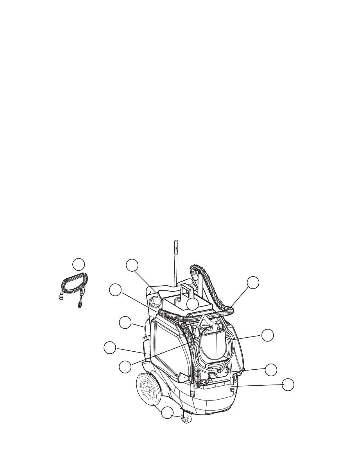
YOUR MACHINE
Operator Handle (1): Operator holds onto this handle to move the machine from one location to
another.
Solution Tank Lid (2): This lid screws off so the tank can be filled. The solution fill hose is
tethered to the lid, and hangs inside the arm of the Operator Handle.
Maid’s tote and Recovery tank lid (3): This removable container holds often-used items and has a
handle for easy carrying. The recovery tank lid sits under the maid’s tote and cov ers the opening in the
Recovery T ank. This is wher e the operator can access the tank to clean it and the ball float cage. The
tank can be flushed out by running clean warm water into this opening and laying the open drain hose into
a bucket or drain.
Recovery Hose (4): Waste water is picked-up thr ough this hose.
Spray Hose (5): This hose delivers water from the machine to the cleaning tool.
Drain Hose (6): This hose is used to empty the recovery tank. NOTE: hold the end of the hose above
the water level in the tank to avoid sudden, uncontrolled flow of waste water when you remove the cap,
then lower the hose slowly to control the rate of discharge.
Quick Disconnect (7): Point of attachment for the Spray Hose (5).
Castors and Wheels (8): Castors pivot for ease of steering, and large back wheels make it easy to roll
the machine from location to location.
Chemical Feed Lines (9): These clear tubes connect the cleaning chemical containers to the machine
where the chemical can be siphoned into the outlet water from the pump. Metering tips -- used to change
the ratio of water to chemical -- are installed here.
Switch Plate (10): The machine’s on/off switches for the vacuum and f or the pump are located here
and this is where the valve to change chemical feeds is located.
Power Cord (11): The 25 ft. power cord connects to a power cord pigtail on the rear of the machine.
Chemical Container Holders (12): T wo molded-in bottle holders for chemical jugs.
11
12
1
4
2
3
9
5
6
10
7
8

KNOW YOUR SWITCH PLATE
O
I
O
COLOR HOLE SIZE MIX RATION FLOW RATE
Orange 0.007 1 to 128 7,81 ml per 1 l
Pink 0.012 1 to 64 19,53 ml per 1 l
Dark Green 0.014 1 to 50 23,44 ml per 1 l
Yellow 0.016 1 to 32 39,06 ml per 1 l
Light Blue 0.020 1 to 20 46,87 ml per 1 l
Burgandy 0.022 1 to 15 70,33 ml per 1 l
Black 0.048 1 to 5 156,27 ml per 1 l
METERING TIPS
1
2
4
Vacuum Switch (1): turns on the vacuum motor.
Chemical Valve (2): switches between the two chemical containers. When the selector is pointed
straight down, the valve is off and neither chemical is selected. When the selector is pointed directly
towards one or the other symbols, that chemical is selected.
Solution Pump Switch (3): turns on the solution pump.
Quick Connect (4): this is where solution comes out of the machine and the attachment point for
the solution hose.
3
METERING TIPS
The chemical metering tips allow you to select the ratio of chemical to water, as the water flows out of
the machine. Insert the correct metering tip for the desired mixture into the chemical siphon tube.

SET-UP AND USE
1) Insert the appropriate metering tips into the chemical feed lines (see illustration, page 5).
2) Fill the holding tank with warm water (not exceeding 54 °C). Do not add any chemical to the tank.
3) Prepare the area for cleaning by emptying waste receptacles, clearing debris, removing paper
products, blowing out vents, and sweeping floors.
4) Connect the 25 ft power cord to the pig-tail on the rear of the machine.
5) PRIME THE PUMP: Attach the priming hose to the outlet quick disconnect and place the open end
of the hose into the recovery tank. Turn on the pump and let it run until the pump is completely
primed (no visible air in the water stream). T urn the pump off.
NOTE: prime the machine before you place the chemical feed tubes into chemical containers.
6) Disconnect the priming hose and attach the solution hose to the quick disconnect.
7) Attach the spray gun to the other end of the solution line.
8) Place chemicals in the molded-in chemical bottle containers on the rear of the machine. Insert one
of the feed lines into one of the chemical containers. Secure the line by screwing on the cap. The
chemical will feed from which ever container the selector valve on the switch plate is turned towards
and when the gun is used in the low pressure setting. Use chemicals with a pH of between 5 and
10. Never add chemicals to the clean water tank.
9) Set the spray gun to low pressure by sliding the pressure selector forward (low pressure = forward;
high pressure = back).
10) T urn on the pump switch (push but ton) and spray through the gun f or a few seconds to fill the
line with solution.
11) Apply the chemical to the walls and fixtures from the bottom up. Spray the floor last as you work
your way out of the room.
12) Allow the chemical to work for the proper amount of dwell time, according to the chemical
manufacturer’s directions. Agitate heavily soiled areas with a scrub brush.
13) T urn off the chemical injector valv e by turning the selector to the down position.
14) Set the spray gun to high pressure and rinse the area from the top down.
15) Connect the vacuum hose, attach the squeegee, and turn on the vacuum (rocker switch).
16) Squeegee off the mirrors, pick up the liquid off the floor with the floor tool. If you have the
optional blow dry hose, use it to dry the fixtures.
17) Drain the recovered water into a utility sink or toi let. NOTE: Keep the top of the drain hose higher
than the water level in the tank to avoid uncontrolled discharge of water when you open the cap
onthe hose.
CAUTION
T o avoid v acuum motor damage, always use a defoamer any time foam is pr esent.
Before you turn on the vacuum always make sure the filter screen on the ball float is clean and that the
ball can travel freely .
RE-PRIMING THE PUMP
If the pump looses prime between jobs, follow the instructions to PRIME THE PUMP, above. If that
doesn’t get water flowing, put the priming hose into the vacuum inlet hose barb and cover the rest of
the space around the priming hose with your hand. T urn on the v acuum (with the pump also running)
and let the suction of the vacuum assist in getting water into the pump.

O
I
O
25
4
26
24
14
13
3
12
15
11
23
5
18
17
22
16
16A
17A
21
9
20
2
6
7
10
1
01-11-09
8
19
APC 328

APC 328
PART LIST
220-240V220-240V
220-240V
220-240V220-240V
ITEM PART No. DESCRIPTION
1 600732869 Lid and gasket, recovery tank
2 600732846 Hose kit, drain, priming and vac inlet
3 600732882 Hose kit, water and chemical metering
4 600732871 Metering tips and chemical injector
5 600732889 Filter , electrical noise suppression
6 600732883 Vacuum motor kit, with gask et and hose
7 600732884 Tank, recovery , complete
8 600732874 Vacuum inlet kit
9 600732886 Switch plate kit, complete
10 600732885 Switch kit, two switches
11 600732876 Pallet, component mounting, complete
12 600732848 Lid, with fill hose, holding tank/base
13 600732858 Fasteners kit
14 600732856 Lid and ring, 4”
15 600732873 Power cord, EU
600732887 Power cord, UK
16 600732866 Pump and motor , complete
16A 600732868 Motor , pump drive
17 600732865 Pump, solution, complete, no motor
17A 600732875 Pressure regulator , for solution pump
18 600732877 Filter , pump in-line, with hoses
19 600732854 Vacuum recovery hose, complete, 8 M
20 600732855 Solution hose assembly , 8 M
21 600732847 Quick disconnect kit, with washers
22 600732859 Grommets and foam
23 600732849 Cap, drain, and brass fitting
24 600732850 Castor kit, includes bracket
25 600732852 Wheel kit
26 600732879 Holding tank/base, complete
MISCELLANEOUS PARTS
600732872 Label kit, APC 328
600732888 Repair kit, solution pump
REV B 11-09

TOOLS AND ACCESSORIES
Tool kit, standard, complete
1
3
5
2
4
10
12
1 600732862 Squeegee, hand held
2 600732893 Handle, for hand held squeegee
3 600732855 Solution hose
4 600732863 Brush, dual surface
5 600732894 Handle, two piece
6 600732895 Squeegee, for floor
7 600732896 Gun, spray , dual pressure
8 600732860 Handle, straight, black
9 600732881 Tote, carry all
10 600732853 Metering tips, two each
11 600752127 Priming hose, for solution pump
12 600732854 Recovery hose
11
7
8
9
6
Optional accessories
1 600732897 Frame, micro fiber mop
2 600732898 Mop, micro fiber (6)
3 56380888 Squeegee assembly , 61 cm
4 56209089 Squeegee assembly , 76 cm
5 600732901 Mount assembly , mechanical, for squeegee heads
6 600732864 Blower hose assembly , with nozzle
3 or 4
1
2
5
6

MAINTENANCE
1) Use only approved chemicals at the recommended mix ratios. All chemicals should be
added through the feed system and NOT added directly to the water in the solution
tank to prevent possible damage to the pump, seals, or other components.
2) For optimum performance, flush the Chemical Feed lines after every job by replacing
the chemical containers with containers of clear water and spraying through the gun
until the fluid stream is clear . See the Maintenance S chedule, below.
3) The pump seals and/or valves in the high pressure pumps may need to be replaced
after about 1000 hours of use, if the pump begins to loose performance or to leak.
The pressure regulator valve may need to be when a drop in the spraying pressure at
the tool is apparent.
MAINTENANCE SCHEDULE
ITEM DAILY WEEKLY QUARTELY YEARLY
Flush chemical lines
Check/clean vac inlet filter
Clean solution filter
Check vacuum motor airways
Check pump for leaks
Check vacuum motor brushes *
x
x
x
x
X
x
x
* Have your distriburor check the carbon brushes once a year or after about 500 hours of operation.
TECHNICAL SPECIFICATIONS
Vacuum motor:
Water lift:
Air flow:
T ank constructions:
Height:
Machine weight:
2-stage, 8 amp
23 kpa
100 CFM
Rotationally molded polyethylene
98 cm X 59 X 86.5 cm
50 kg

NOTES:
APC 328
ALL PURPOSE CLEANER
 Loading...