

Page 1

M314E 04.7.CF.3(1/5)
Inverted Microscope
ECLIPSE TE2000-E
ECLIPSE TE2000-U
ECLIPSE TE2000-S
Instructions
Page 2

Page 3

Thank you for purchasing the Nikon products.
This instruction manual is written for the users of the Nikon’s inverted microscopes “ECLIPSE TE2000-E, ECLIPSE
TE2000-U, ECLIPSE TE2000-S” and describes the basic operations of the microscope.
To ensure correct usage, read this manual carefully before operating the instrument.
• It is prohibited to reproduce or transmit th is manual in part or whole without Nikon’s expressed permission.
• The contents of this manual are subject to change without notice.
• Although every effort has been made to ensure the accuracy of this manual, if you note any points that are unclear
or incorrect, contact your nearest Nikon representative.
• Some of the products described in this manual may not be included in the set you have purchased.
• Be sure to read the instruction manual for any other products used in combination with the microscope.
• If you purchased the TE2000-E model, be sure to read the instruction manual supplied with the T-HUBC HUB
controller.
• If you are using the TE2000-U/S together with the T-HUBC HUB controller, be sure to read the instruction manual
supplied with the T-HUBC HUB controller.
Warning / Caution symbols used in this manual
Although Nikon products are designed to provide you with the utmost safety during use, incorrect usage or
disregard of the instructions can cause personal injury or property damage and will lead to the forfeiture of all
claims against warranty. For your safety, read the instruction manual carefully and thoroughly before using the
instrument. Do not discard this manual but keep it near the product for easy reference.
In this manual, safety instructions are indicated with the symbols shown below. Be sure to follow the
instructions indicated with these symbols to ensure correct and safe operation.
Symbol Meaning
Disregarding instructions marked with this symbol may lead to death or serious
injury.
Disregarding instructions marked with this symbol may lead to injury or property
damage.
Meaning of symbols used on the equipment
The symbol appearing on the product indicates the need for caution at all times during use.
Always refer to the instruction manual and read the relevant instructions before manipulating any part to which
the symbol has been affixed.
Symbol Meaning
Caution for heat.
This marking at the top part of the Dia-illuminator and the 12V100W lamphouse calls your
attention on the following;
• Lamphouse becomes very hot during and immediately after the illumination.
• Risk of burns. Do not touch the lamphouse during and immediately after the illumination.
• Make sure that the lamphouse is sufficiently cool before the lamp replacement.
Biohazard
This symbol on the stage calls your attention to the following:
• Spillage of a sample from a vessel onto the microscope presents a biohazard risk.
• To avoid biohazard contamination, do not touch the contaminated portion with your bare
hands.
• Decontaminate the contaminated portion according to the standard procedure of your
laboratory.
1
Page 4

1. Intended use of the equipment.
This microscope is intended mainly for use in microscopic observation and in the micr omanipulation of
living cells and tissue using diascopic (transmitted) and episcopic (reflected) illumination. It is designed
for the main purposes of experimentation and observation, in hospitals or other laboratories, of such cells
and tissue within the fields of genetics, immunology, physiology, pharmacology, neurology, cellular biology,
and molecular biology.
2. Do not disassemble.
Disassembly may cause malfunction and / or electrical shock, and will lead to the forfeiture of all claims
against warranty.
experience any problem with the microscope, notify your nearest Nikon representative.
3. Check the Input Voltage.
This microscope uses a power supply for the lamp.
When using the power supply TE-PS30 or TE-PSE30:
Make sure that the input voltage indication on the rear panel matches your regional voltage supply. If the
voltages do not match, do not use the microscope; instead, notify your nearest Nikon representative.
Using the power supply with the wrong input voltage may cause a short circuit or fire. It may also cause
damage to the microscope.
When using the power supply TE2-PS100W:
If you are using the power supply TE2-PS100W, there is no need to check the input voltage since the input
voltage of this power supply is AC 100-240V and can be used at any place in the world.
4. Check the AC adapter of the HUB controller (when using the T-HUBC HUB controller).
The HUB controller is powered by the AC adapter. Be sure to use the specified adapter model meeting the
requirements given below. Use of any other type of adapter can result in malfunction , excessive heating,
and/or fire.
• To prevent malfunction and/or fire, be sure to use the AC adapter in a well-ventilated location. To
ensure that it radiates heat properly and does not overheat, never cover or place any object on the
adapter.
• To prevent malfunction, always turn off the power switch (switch to “O”) of the HUB controller before
attaching the AC adapter.
• Specified AC adapter
Manufacturer: PHIHONG ENTERPRISE (Taiwan)
Model: PSA30U-120 (N)
Rated input voltage: AC 100-240 V, 0.7 A, 50/60 Hz
Voltage fluctuation: ±10%
Rated output voltage: DC 12 V
Rated output current: 2.5 A
Others: UL Listed product, GS approved, CE satisfied
Do not disassemble any part other than those described in this manual. If you
5. Power cord for power supply and the power cord for AC adaptor of the HUB controller
To prevent electric shock, always turn off the power switch (switch to “O”) for the power supply and the HUB
controller before attaching or detaching the power cord. Use one of the power cords specified below. Use of an
improper power cord can result in fire or other hazard. Also note that the power supply is classified as subject
to protection class I against electric shock. Therefore, be sure to connect it to a protective ground terminal.
• Using units in areas where the supply voltage is 100 to 120 V
UL Listed detachable power cord set, 3 conductor grounding Type SVT, No. 18 AWG, 3 m long maximum,
rated at 125 V AC minimum.
• Using units in areas where the supply voltage is 220 to 240 V
Approved according to EU/EN standards, 3 conductor grounding Type HO5VV-F, 3 m long maximum,
rated at 250 V AC minimum.
6. Heat from the light source.
• The lamp and the lamphouse become extremely hot by the lamp illumination. To avoid burns, do not
touch the lamphouse while the lamp is lit or for thirty minutes after it has been turned off.
• To avoid the risk of fire, do not place fabric, paper or highly flammable volatile materials such as
gasoline, petroleum benzine, paint thinner or alcohol near the lamphouse while the lamp is lit or for
about thirty minutes after it has been turned off.
• The bottom plate of the power supply becomes hot during use. Do not cover up the ventilation holes
on the side of the power supply.
Continued on the next page
2
Page 5

7. Hazardous sample
This microscope is mainly for use in microscopic observation and micromanipulation of living cells and
tissue cultures in Petri dishes, microtiter plates, etc.
When handling a sample, check to determine whether the sample is hazardous. Handle hazardous
samples according to the standard procedure of your laboratory. If the sample is of an infectious
nature, wear rubber gloves to avoid infection, and be careful not to spill the sample. In the event of
spillage of a sample from a vessel onto the microscope, decontaminate the contaminated portion
according to the standard procedure of your laboratory.
1. Check the combination of the lamp, dia-illuminator and power supply.
The dia-illuminator and the power supply must be used in correct combination against the ratings of the
lamp and the regional voltage supply. See page 38 to find out the correct combination of these items.
Using the equipment in wrong combination will lead to fire, electric shocks or malfunction of the
equipment.
2. Turn off the power during assembly, connection/disconnection of the cords, and lamp
replacement.
To prevent electric shocks and/or malfunction, always turn off the power switch of the power supply and
the T-HUBC HUB controller (flip it to the { side) and unplug the power cord from the wall outlet before
assembly, connecting or disconnecting of the cords, and the lamp replace ment.
3. Cautions on lamp replacement.
To avoid burns, wait at least 30 minutes after the lamp is turned off so that the lamp can cool sufficiently.
To avoid electric shocks and malfunction, always turn off the power switch (flip it to the { side) and unplug
the power cord from the wall outlet before lamp replacement.
Securely attach the lamphouse cover to the lamphouse after replacing the lamp. Never light the lamp
while the lamphouse cover is open. Do not break used lamps; instead dispose of them as special
industrial waste or according to the laws applicable to your municipal waste system.
4. Do not wet the microscope.
If the instrument gets wet, a short circuit may result that may cause malfunction or abnormal heating. If
you accidentally spill a liquid on the instrument, immediately turn off the power switch (flip to the { side)
and unplug the power cord from the wall outlet. Then use a dry cloth to wipe away the moisture. If any
liquid gets inside the instrument, do not use it; instead, notify your nearest Nikon representative.
5. Weak electromagnetic waves.
This microscope emits weak electromagnetic waves. The accuracy of any precision electronic equipment
may be adversely affected if positioned too close. If the microscope affects TV or radio reception, move
the radio or TV further away from the microscope.
6. Cautions on assembling and installing the microscope.
• Be careful not to pinch your fingers or hands during the assembly.
• The scratches and dirt such as fingerprints on the optical parts (such as lens and filters) will adversely
affect the microscope image. Be careful not to scratch or directly touch the lens and filters.
• This product is a precision optical instrument. Using or storing it under unsuitable conditions may
damage it or may have an adverse effect on its accuracy. See the installation conditions on page 4 and
use the product in an adequate environment.
7. Cautions on moving the microscope.
When moving the microscope, do not hold it by the focusing knobs, eyepiece tube, stage, dia-illuminator
etc., since these parts can be damaged, or they could come off. Hold the microscope by the bottom front
and bottom rear.
8. Be careful of the protruding rack of the T-SR rectangular stage.
The rack of the T-SR rectangular stage will protrude by the stage movement. Be careful not to strike your
hands against the rack when reaching the focusing knobs or revolving nosepiece. You may get yourself
hurt by the edge of the rack.
Continued on the next page
3
Page 6

9. Disposal of the microscope
To avoid biohazard risk, dispose of the microscope as contaminated equipment according to the standard
procedure of your laboratory.
Notes on handling the microscope
1. Handle the microscope gently.
This product is a precision optical instrument. Handle it carefully, and do not subject it to strong shocks.
The precision of the objectives in particular can be adversely affected even by weak shocks.
2. Dirt on the lens.
The scratches and dirt such as fingerprints on the optical parts (such as lens and filters) will adversely affect the
microscope image. If these parts get dirty, clean them following the instructions described on “Care and
maintenance” at the end of this manual.
3. Dirt on the lamps.
Do not touch the lamp by bare hands. Dirt or fingerprints on the lamp will cause uneven illumination and shortens
the life of the lamp. When handling lamps, wear gloves.
4. Installation location.
Using or storing the microscope under unsuitable conditions may damage it or may have an adverse effect on its
accuracy. The following conditions should be kept in mind when selecting the installation location.
• Choose a flat surface with little vibration.
• Choose a location less exposed to hazards in the event of collisions, earthquakes, or other potential disasters. If
required to keep the device from falling, use strong rope or other means to secure the microscope to the working
desk or to another heavy, stable item.
• Avoid a brightly lit location such as a room that receives direct sunlight.
• Choose a location that is free from dust or dirt.
• Do not install the microscope in a warm (60°C or more), humid (85% or more) location. (Mold or condensation
will form on the lenses and filters.)
• Leave enough space against the nearby wall since the lamphouse will become hot by lamp illumination.
• When using the “T-DH dia-illuminator 100W”, leave a certain space between the microscope and the nearby wall to
allow the user to look at the caution symbols on the dia-illuminator and the lamphouse. If you are planning to use
the tilting function of the “T-DH dia-illuminator 100W”, even more space is needed for the illuminator to tilt
backward.
• The room light just above the microscope may come into the objective as an extraneous light. (Especially when
using a condenser lens with longer working distance such as SLWD, ELWD and LWD lenses.) To avoid this, we
recommend to turn off the room light above the microscope when observing the image.
5. Focusing knobs.
• Never turn the focus knobs on the left and right sides of the microscope in opposite directions at the same time,
as doing so can result in damage to the microscope.
• Turning the coarse focus knob as far as it will go and then attempting to turn it further will result in damage to the
microscope. Never use undue force to turn the knob.
• (For TE2000-E only) The coarse focus knob turns in sync with motorized Escape/Refocus movements. To prevent
malfunctions, avoid contact with the coarse focus knob during motorized Escape/Refocus movements.
6. Protect the ports.
When not using any of the ports, be sure to attach the supplied cap to it. If not, extraneous light and dusts will enter
the microscope.
4
Page 7

Contents
Warning / Caution symbols used in this manual................................................... 1
Meaning of symbols used on the equipment ......................................................... 1
............................................................................................................. 2
! ............................................................................................................. 3
Notes on handling the microscope........................................................................ 4
I. Parts of the microscope and their names .................................................... 6
1. Eyepiece tubes and eyepieces.................................................................... 7
2. Microscope base....................................................................................... 8
3. Dia-illuminators ......................................................................................13
4. Condensers ............................................................................................14
5. Stages, focusing module ..........................................................................15
6. Microscope rear ......................................................................................16
7. Power supplies........................................................................................17
II. Microscopy ................................................................................................ 18
1. Microscope system consisting of TE2000-U, dia-illuminator 100W,
system condenser, and T-TD eyepiece tube D .............................................20
2. Microscope system consisting of TE2000-S, dia-illuminator 30W,
SLWD condenser, and T-TS eyepiece tube S................................................25
3. Microscope system consisting of TE2000-E, dia-illuminator 30W,
SLWD condenser, and T-TS eyepiece tube S................................................29
4. Photomicrography (using a 35-mm camera mounted on the front port) .........34
III. Operation of each part .............................................................................. 37
1. Power ON/OFF ........................................................................................38
2. Brightness adjustment .............................................................................39
3. Optical path switching..............................................................................40
4. Using filters ............................................................................................42
5. Using field diaphragm ..............................................................................42
6. Using condenser aperture diaphragm.........................................................43
7. Eyepiece tube turret ................................................................................44
8. System condenser...................................................................................44
9. Objectives ..............................................................................................45
10. Diopter adjustment .................................................................................47
11. Focusing module .....................................................................................47
12. T-DH dia-illuminator 100W .......................................................................49
13. T-SR rectangular stage ............................................................................50
14. Photomicrography ...................................................................................51
IV. Assembly................................................................................................... 54
V. Troubleshooting ........................................................................................ 61
VI. Care and maintenance............................................................................... 64
VII. Technical specifications............................................................................. 65
System diagram ........................................................................................ 70
5
Page 8

I. Parts of the microscope and their names
I. Parts of the microscope and their names
Parts of the microscope can be selected according to your purpose.
Exceptionally, the combination of the lamp, dia-illuminator and the power supply is fixed. Never use these
parts in combination other than specified.
(Refer to page 38 for the correct combination of the lamp, dia-illuminator and the power supply.)
The T-HUBC HUB controller, which mounts on the rear side of the microscope, allows the user to control
attached motorized units. For details, refer to the instruction manual provided with the T-HUBC HUB
controller.
Dia-illuminator
P.13
Condenser
P.14
Eyepiece tube
P. 7
Stage
P.15
Microscope rear
P.16
Power supply
P.17
Microscope base
P. 8
This is a photograph of TE2000-U microscope with T-DH dia-illuminator 100W, LHS-H100P-1 12V100W
lamphouse, 12V100W halogen lamp, TE2-PS100W power supply, T-SR rectangular stage, T-TD
binocular eyepiece tube D, CFI 10X eyepieces, T-N6 sextuple nosepiece, system condenser, objectives,
power cord, etc.
6
Page 9

I. Parts of the microscope and their names
1. Eyepiece tubes and eyepieces
The following eyepiece tubes can be mounted on the observation port of the microscope.
T-TD eyepiece tube D
A: Diopter adjustment ring
B: Eyepiece
C: Eyepiece tube turret
T-TS eyepiece tube S
O: Open
B: Bertrand lens (with focusing screw)
C: Close (Shutter)
M: 2.5X magnifier
A: Diopter adjustment ring
B: Eyepiece
T-TERG ergonomic eyepiece tube
A: Diopter adjustment ring
B: Eyepiece
C: Eyepiece tube turret
O: Open
B: Bertrand lens (with focusing screw)
C: Close (Shutter)
T-TI intermediate tube
A: Clamp screw for holding various devices
B: Mount for various devices
such as
Trinocular eyepice tube for upright microscopes
Teaching head
7
Page 10

I. Parts of the microscope and their names
2. Microscope base
Note: Be sure to cover unused ports with supplied caps to prevent the entry of external light and dust.
TE2000-E, right side
Eyepiece-tube clamp screw
Observation port
Install the eyepiece tube.
Front port
Photo-mask dial
Clockwise turn: OUT
Counterclockwise turn: IN
Intermediate magnification dial
1X: No intermediate magnification
1.5X: 1.5X intermediate magnification for all ports
REFOCUS switch
Raises the objective to the
memorized position.
ESCAPE switch
Lowers the objective to the Escape position.
Fine focus knob
The distance of travel achieved by one rotation of the knob
can be set to Fine, Middle, or Coarse.
The knob is set to Coarse at the factory.
T-RCP remote control pad
Not required when the microscope is controlled using a PC
REFOCUS
COARSE FOCUS
ESCAPE
Objective
Nosepiece
Mount for analyzer
Install the analyzer here
for DIC microscopy.
Adapter clamp screw
Left-side port
Optical path switch-over
section holding screw
This screw is installed for transportation.
Be sure to remove the screw before using the microscope.
TE-2000E, left side
T-HUBC HUB controller
The specified AC adapter is required.
Adapter clamp screw
Right-side port
Bottom port
DIA-LAMP ADJ key
Used to adjust the view field brightness.
This key can be used only
when the T-DH dia-illuminator 100W
is installed.
Turn on the green
indicators.
Light path key
Changes the optical path.
Observation 20%
Front 80%
Observation 100%
Left 100%
Bottom 100%
Stage
Black cover for elevating section
Remove the cover when installing
the epi-fl attachment.
Mount for cassette holder
For the installation of the cassette holder
for epi-fl microscopy
Dia-illumination ON/OFF switch
Brightness adjustment dial
This dial is disabled
when the remote control pad
is used for bright adjustment.
Observation 20%
Right 80%
Coarse focus knob
8
Page 11

I. Parts of the microscope and their names
Note: Be sure to cover unused ports with supplied caps to prevent the entry of external light and dust.
TE2000-U, right side
Eyepiece-tube clamp screw
Observation port
Install the eyepiece tube.
Adapter clamp screw
Front port
Photo-mask dial
Clockwise turn: OUT
Counterclockwise turn: IN
Intermediate magnification dial
1X: No intermediate magnification
1.5X: 1.5X intermediate magnification for all ports
Optical path switch-over dial
1: Observation 100%
2: Observation 20%, Right 80%
3: Not used (Bottom port 100%)
4: Observation 20%, Front 80%
5: Left 100%
Objective
Nosepiece
Mount for analyzer
Install the analyzer here
for DIC microscopy.
Adapter clamp screw
TE2000-U, left side
Right-side port
Fine focus knob
Coarse focus knob
Objective refocusing ring
Forward turn: Release
Backward turn: Lock
Stage
Black cover for elevating section
Remove the cover when installing
the epi-fl attachment.
Mount for cassette holder
For the installation of the cassette holder
for epi-fl microscopy
Dia-illumination ON/OFF switch
Left-side port
Coarse focus torque adjustment ring
Forward turn: Decreases torque
Backward turn: Increases torque
Brightness adjustment dial
This dial is disabled
when the remote control pad is used
for bright adjustment.
Fine focus knob
Coarse focus knob
The bottom port changeover lever is provided on the left-hand side of the TE2000-U bottom port type.
See P. 41 for optical path switching.
9
Page 12

I. Parts of the microscope and their names
Note: Be sure to cover unused ports with provided caps to prevent the entry of external light and dust.
Eyepiece-tube clamp screw
Observation port
Install the eyepiece tube.
Optical path switch-over dial
EYE: Observation 100%
SIDE: Observation 20%, Left 80%
Objective
Nosepiece
Mount for analyzer
Install the analyzer here
for DIC microscopy.
Adapter clamp screw
TE2000-S, right side
TE2000-S, left side
Fine focus knob
Coarse focus knob
Stage
Black cover for elevating section
Remove the cover
when installing the epi-fl attachment.
Mount for cassette holder
For the installation of the cassette holder
for epi-fl microscopy
Dia-illumination ON/OFF switch
Left-side port
Coarse focus torque adjustment ring
Forward turn: Decreases torque
Backward turn: Increases torque
Brightness adjustment dial
This dial is disabled
when the remote control pad is used
for bright adjustment.
Fine focus knob
Coarse focus knob
10
Page 13

I. Parts of the microscope and their names
Various adapters for the front port (TE2000-S is not equipped with front port.)
T-BFA F-mount adapter
Digital still camera with F-mount such as D1 can be mounted.
T-BSLR SLR camera adapter
Single-lens reflex camera such as FE10, F70, F90 and F5 can be mounted.
T-BDCA direct C-mount adapter
Digital still camera for the microscopes such as DXM1200, can be mounted here.
Various adapters for side port
Side port adapter
This adapter is supplied with the microscope.
T-BPA photo adapter
Double port adapter
Various TV adapters
Various adapters for bottom port
(TE2000-U, except for the bottom-port type, and TE2000-S are not equipped with bottom port)
Bottom port adapter
This adapter is supplied with the microscope.
Various TV adapters
11
Page 14

I. Parts of the microscope and their names
T-EFN Focus Knob
(supplied with the TE2000-E only. The knob is incompatible with the TE2000-U and TE2000-S.)
The TE2000-E provides focus adjustment in various positions with the supplied T-EFN focus
knob. You can make fine focus adjustments by connecting the T-EFN focus knob to the T-
HUBC HUB controller AUX connector and by switching the knob selector switch on. (Switching
the selector switch off permits fine focus adjustments using the fine movement knob
provided on the right side of the TE2000-E.)
The T-EFN focus knob is comprised of the focus knob main unit and the base plate, which are
connected by a magnet.
The direction of the T-EFN focus knob can be switched between right and left by changing the
main unit's position relative to the base plate. Note that the focus adjustment knob can be
operated independently with the knob facing up.
Knob rightward rotation (clockwise): Raises the objective (brings the objective
closer to the specimen).
Knob leftward rotation (counterclockwise): Lowers the objective (moves the objective
farther from the specimen).
Fine movement
.
Selector switch
Knob facing left Knob facing right Knob facing up
Caution: The T-EFN focus knob main unit and the base plate are connected by a magnet. Handle carefully.
Lifting them while they are connected may cause the base plate to detach and fall.
12
Page 15

I. Parts of the microscope and their names
3. Dia-illuminators
Dia-illuminators should be used in specified pairs with the lamp (12V100W or 6V30W). A lamphouse is
needed for the T-DH dia-illuminator 100W.
T-DH dia-illuminator 100W and LHS-H100P-1 12V100W lamphouse
A: Field aperture diaphragm lever
B: Filter sliders
C: Condenser refocusing clamp
(Works only when LWD condenser
lens is attached.)
D: Condenser focus knob
E: Condenser clamp screw
F: Condenser mount positioning pin
G: Condenser mount positioning groove
H: Condenser mount rotation clamp
screw
I: Condenser centering screw
J: Condenser mount (rotatable)
K: LHS-H100P-1 12V100W lamphouse
L: Lamphouse clamp screw
M: Lamphouse cover clamp screw
N: Condenser holder (removable)
O: Condensr holder clamp screw
P: Lamp cable
Q: Condenser holder fall-stop screw
T-DS dia-illuminator 30W
A: Dustproof slider (removable)
B: F stop slider (removable)
C: Condenser mount
D: 6V30W lamp housing
E: Filter slider
F: M4 screw holes for additional device mounting
13
Page 16

I. Parts of the microscope and their names
4. Condensers
System condenser
When mounted on When mounted on T-DS dia-illuminator 30W
T-DH dia-illuminator 100W (Only for HMC observation.)
A: Condenser aperture diaphragm
B: Condenser module
C: Condenser module clamp screw
D: Condenser lens
(3 types available; ELWD, LWD, HMC)
E: Annular diaphragm centering screw
(on Ph modules only)
ELWD-S condenser SLWD condenser
A: Centering handle clamp screw
B: Centering handle
C: Turret
A
B
C
SLWD condenser can only be mounted on
T-DS dia-illuminator 30W.
14
Page 17

5. Stages, focusing module
T-SR rectangular stage
A: Stage ring
B: Y-axis stage movement knob
C: X-axis stage movement knob
T-SP plain stage
A: Stage ring
I. Parts of the microscope and their names
15
Page 18

I. Parts of the microscope and their names
6. Microscope rear
Mount for epi-fl
attachment
Mount for T-HUBC
HUB controller
LAMP CTRL
connector Connect
the power supply
or HUB controller.
MIC CTRL1 connector
Connect the HUB controller.
Not provided on TE2000-U
or TE2000-S
MIC CTRL2 connector
Connect the HUB controller.
Not provided on TE2000-U
or TE2000-S
(The HUB controller's connectors are attached with various motorized units.)
Epi-fl attachment
NOSEPIECE
Connect the T-ND6-E
sextuple motorized
DIC nosepiece.
ANALYZER
Connect the T-A-E
motorized DIC analyzer
Connect the T-FLEW-E
EX FILTER
EX filter wheel.
FL SHUTER
Connect the T-FL-E
motorized epi-fl
attachment.
REMOTE
Connect the T-RCP
remote control pad.
and epi-fl attachment installed to the rear side of the microscope.
The photo shows the T-HUBC HUB controller
TE-PS
Connect the power supply.
T-HUBC HUB controller
This device controls
the attached motorized units.
It must be installed when the
TE2000-E is used.
Installation of this controller
is optional on the TE2000-U
and TE2000-S.
CONDENSER
Connect the T-CT-E motorized
condenser turret.
FL BLOCK
Connect the T-FLC-E motorized
cassette holder.
BA FILTER
Connect the T-FLBW-E
BA filter wheel.
AUX
Connect the T-EFN focus knob here.
(The T-EFN focus knob is supplied
with the TE2000-E only.)
SHUTTER
Refer to "VI-21 Connection of
external equipment"
in the instruction manual supplied
with the HUB controller.
STAGE
Refer to "VI-21 Connection of
external equipment"
in the instruction manual supplied
with the HUB controller.
PC
Connect a PC.
EXP
Refer to "VI-22 Connection to the
EXP connector"
in the instruction manual supplied
with the HUB controller.
16
Page 19

7. Power supplies
t
The bottom of the power supply becomes hot while it is in use. Do not obstruct the
air vents on the sides of the power supply.
TE2-PS100W power supply
Pilot lamp
Turns on when the
power is on.
I. Parts of the microscope and their names
EXTERNAL switch
Turning the switch ON activates the brightness
adjustment dial on the microscope or the DIA-LAMP
adjustment key on the T-RCP remote control pad
(when the T-DH dia-illuminator 100W is used).
Turning this switch OFF activates the brightness
adjustment dial on the power supply.
OUTPUT connector
This is the lamp output
connector.
Connect the lamp cable from
the dia-illuminator to this
connector.
TE-PS30 power supply (for 100−−−−120 V area)
TE-PSE30 power supply (for 220−−−−240 V area)
Pin 2 : ditto
CTRL connector
Connect the LAMP CTRL connector
on the rear of the microscope using
a control cable. This device canno
be used to connect the T-HUBC
HUB controller.
Pin 3 : Lamp ON/OFF: Input
(Open: ON, 0 V: OFF)
Pin 4 : 0 V
17
Page 20

II. Microscopy
II. Microscopy
When using the system consisting of the TE2000-E and dia-illuminator 100W
For the microscopy procedure, refer to the instruction manual supplied
with the T-HUBC HUB controller.
The T-HUBC HUB controller, which mounts on the rear of the microscope, controls the operations of all
attached motorized units. Note that when the T-HUBC HUB controller is mounted on the rear of the
microscope, the microscope cannot be operated in the same way as when manual operation is used. Be
sure to read the instruction manuals supplied with the T-HUBC HUB controller and T-RCP remote control
pad to ensure proper preparation and operation of the microscope.
Note that the following two operations cannot be controlled using the T-HUBC HUB controller.
• 6V30W lamp ON/OFF: Use the dia-illumination ON/OFF switch on the microscope main body.
• 6V30W lamp voltage adjustment: Use the brightness adjustment dial on the microscope main body or
power supply.
When using the TE2000-U or TE2000-S
with the T-HUBC HUB controller mounted on the rear
For the microscopy procedure, refer to the instruction manual supplied
with the T-HUBC HUB controller.
The T-HUBC HUB controller, which is mounted on the rear of the microscope, controls the operations of all
attached motorized units. Note that when the T-HUBC HUB controller is mounted on the rear of the
microscope, the microscope cannot be operated in the same way as when manual operation is used. Be
sure to read the instruction manuals supplied with the T-HUBC HUB controller and T-RCP remote control
pad to ensure proper preparation and operation of the microscope.
Note that the following five operations cannot be controlled using the T-HUBC HUB controller.
• Optical path switchover: Use the optical path switchover dial on the microscope main body.
• Vertical focus motion control from PC: Use the fine/coarse focus knob on the microscope main body.
• Z-axis display: The Z-axis position data cannot be obtained.
• 6V30W lamp ON/OFF: Use the dia-illumination ON/OFF switch on the microscope main body.
• 6V30W lamp voltage adjustment: Use the brightness adjustment dial on the microscope main body or
power supply.
18
Page 21

II. Microscopy
The TE2000 series is the system microscopes that can be flexibly configured to meet specific applications. There are three
main body types, two types of dia-illuminators, four types of eyepiece tubes, and various other parts variations. The
following section describes the basic microscopy procedure based on three standard system configurations.
• Refer to "III. Operation of each part" for details on each operation.
• If your microscope is configured differently from the system described in the manual, refer to the applicable
explanations in "III. Operation of each part."
• If your microscope is not pre-assembled, see "IV. Assembly" first.
• If your microscope is mounted with the epi-fl, DIC, or other attachments, refer to the instruction manuals supplied with
the respective attachments.
1. Microscope system consisting of TE2000-U, dia-illuminator 100W, system condenser, and T-TD eyepiece
tube D
1-1. Bright-field microscopy
1-2. Phase-contrast microscopy
2. Microscope system consisting of TE2000-S, dia-illuminator 30W, SLWD condenser, and T-TS eyepiece
tube S
2-1. Bright-field microscopy
2-2. Phase-contrast microscopy
3. Microscope system consisting of TE2000-E, dia-illuminator 30W, SLWD condenser, and T-TS eyepiece
tube S
3-1. Bright-field microscopy
3-2. Phase-contrast microscopy
4. Photomicrography (using a 35-mm camera mounted on the front port)
Microscope system consisting of TE2000-U, dia-illuminator 100W, system condenser, and T-TD eyepiece
tube D
Supplementary information
When conducting bright-field or phase-contrast microscopy with a microscope system consisting of the TE2000-E,
dia-illuminator 100W, system condenser, and T-TD eyepiece tube D, refer to the instruction manual supplied with the
T-HUBC HUB controller since it provides detailed information.
Before using the instrument, read the "WARNING," "CAUTION," and "Notes on handling the microscope" sections at
the beginning of this manual and be sure to follow the instructions therein.
Also refer to the instruction manuals supplied with other products (such as the epi-fl and DIC attachments) used in
combination with the microscope, and follow the instructions written.
19
Page 22

II. Microscopy
”
1. Microscope system consisting of TE2000-U,
dia-illuminator 100W, system condenser,
and T-TD eyepiece tube D
The following instructions are based on a microscope equipped with the parts listed below.
TE2000-U microscope
T-TD eyepiece tube D
CFI 10X eyepiece
T-DH dia-illuminator 100W
LHS-H100P-1 12V100W lamphouse
12V100W halogen lamp
TE2-PS100W power supply
System condenser
LWD condenser lens
Condenser module for bright-field microscopy
Condenser module for phase-contrast microscopy
T-SR rectangular stage
T-N6 sextuple nosepiece
Objectives for bright-field microscopy
Objectives for phase-contrast microscopy
Others
1-1. Bright-field (BF) microscopy
Key point: Detach all optical elements required for other types of observation from the optical path. Position the
condenser correctly (adjust the focus and centering), and adjust the clarity of the image by moving the
“aperture diaphragm”.
1. Reset the convenient functions.
1) Turn the “condenser refocusing clamp” on the dia-
illuminator counterclockwise to release.
2) Set the “eyepiece tube turret” to position < O >.
3) Set the “intermediate magnification dial” on the right side
of the microscope to position < 1X >.
4) Turn the “objective refocusing ring
focus knob on the right side of the microscope
counterclockwise to release.
behind the fine/coarse
20
Page 23

2. Turn on the dia-illumination.
”
”
”
”
”
r
1) Set the “EXTERNAL switch” on the rear side of the power
supply to ON.
2) Turn on the “power switch” of the power supply. (Flip the
switch to .)
3) Press the “dia-illumination ON/OFF switch
of the microscope to turn on the lamp.
3. Adjust the lamp to ensure color fidelity.
1) Set the “brightness adjustment dial
microscope to the < 12V100W > indication.
2) Move the “NCB11 filter” on the dia-illuminator into the
optical path.
3) Move the “ND4 filter
path.
on the dia-illuminator into the optical
on the left side
on the left side of the
II. Microscopy
4. Adjust the optical path.
1) Move the < 10X > objective into the optical path.
2) Set the “optical path switchover dial
microscope to position < 1 >. (-> Direct 100% light to the
observation port.)
3) Raise the “field diaphragm lever” on the dia-illuminator
completely to open the field diaphragm fully.
4) Turn the “aperture diaphragm lever
to the right limit to open the “apertur e d iaphragm” fully.
5) Turn the condenser focus knob to lower the condenser
mount to the lowest position.
Supplementary informat ion
When the system condenser is mounted with the “ELWD
condenser lens”, position the condenser mount at the
location about 1 cm below the uppermost position.
When using the “ELWD-S condenser”, position the
condenser mount at the location about 2 cm below the
uppermost position.
5. Set the microscope for bright-field microscopy.
1) Set the “condenser turret” to position < A >.
6. Adjust the diopter and interpupillary distance.
1) Turn the “photo-mask dial” on the front side of the
microscope counterclockwise to move the photo-mask into
the optical path.
2) Look into the left eyepiece with your left eye. Turn the
“diopter adjustment ring” of the left eyepiece to bring the
double crosshairs of the photo-mask into focus.
3) Look into the right eyepiece with your right eye. Turn the
“diopter adjustment ring” of the right eyepiece to bring the
double crosshairs of the photo-mask into focus.
on the right side of the
on the system condense
Turn the diopter adjustment ring
so that the double crosshairs come into focus.
Adjust the interpupillary distance
to consolidate the view fields of both eyepieces.
21
Page 24

II. Microscopy
Field of view
Field diaphragm image
Field of view
Field diaphragm image
”
”
4) Turn the “photo-mask dial” on the front side of the
microscope clockwise to remove the photo-mask from the
optical path.
5) Adjust the distance between the eyepieces to consolidate
the view fields of both eyepieces.
7. Adjust the focus.
1) Place a specimen on the stage.
2) While looking into the eyepieces, turn the “fine/coarse
focus knob” to bring the specimen into focus.
8. Center the condenser.
1) Make sure that the < 10X > objective is in the optical path.
2) Lower the “fie ld dia phragm lever” on the dia-illuminator
until the field diaphragm image appears in the field of view.
3) Turn the “condenser focus knob” to bring the field
diaphragm image into focus.
4) Turn the two “condenser centering screws” to move the
field diaphragm image to the center of the view field.
5) Select the < 40X > objective.
6) Adjust the posit ion of the “fie ld diaphragm lever” on the
dia-illuminator until the size of the field diaphragm image is
about the same as that of the view field.
7) Turn the two “condenser centering screws” on the dia-
illuminator to move the field diaphragm image to the center
of the view field.
9. Conduct observation.
1) Select an objective of desired magnification.
2) Move the “aperture diaphragm lever” on the system
condenser to set the opening to 70 to 80% of the N.A.
(numerical aperture) of the objective. (-> Set the
“eyepiece tube turret
lens focusing screw to perform focusing, and adjust the size
of the image while viewing the exit pupil of objective and
aperture diaphragm image.)
3) Move the “field diaphragm lever” on the dia-illuminator
until the size of the field diaphragm image is about the
same as that of the view field.
4) Move the “ND filter
optical path to adjust the brightness of the view field.
Supplementary informat ion
If precise color fidelity is not required, the brightness
can be adjusted by varying the lamp voltage using the
“brightness adjustment dial” on the left side of the
microscope.
to position < B >, turn the Bertrand
on the dia-illuminator in and out of the
22
Page 25

II. Microscopy
”
”
”
”
10. Change the specimen.
Use the “objective refocusing ring” on the microscope main
body, the “tilting” of the dia-illuminator, and the
“condenser refocusing clamp” to facilitate specimen
replacement.
11. After the completion of microscopic procedures
1) Turn off the “power switch” of the power supply. (Flip the
switch to {.)
2) After the lamphouse section cools, place the vinyl cover on
the microscope.
1-2. Phase-contrast (Ph) microscopy
Key point: Move Ph objective and condenser module with the same Ph code into the optical path, and align (center) the
phase plate in the objective and the annular diaphragm in the condenser module before conducting
microscopy.
1. Focus on the specimen using bright-field (BF) microscopy.
2. Set the microscope for phase-contrast microscopy.
1) Move a Ph objective into the opt ical path.
2) Turn the “condenser turret
as that of the objective placed in the optical path in step 1).
3) Turn the “aperture diaphragm lever” on the condenser to
the right limit to open the “aperture diaphragm” fully.
Supplementary informat ion
If the “aperture diaphragm
path of the annular diaphragm will be restricted,
preventing the realization of the appropriate phase
contrast effect.
4) Raise the “field diaphragm lever” on the dia-illuminator to
the limit to open the field diaphragm fully.
Supplementary informat ion
When “ELWD-S condenser” is used:
The “aperture diaphragm” of the “ELWD-S condenser”
works only with the bright-field optica l path, and it does
not affect the phase-contrast optical path. Therefore,
there is no need to open the “aperture diaphragm” fully
in step 3).
All the annular diaphragms of the “ELWD-S condenser
will be simultaneously centered when the PhL
diaphragm is centered. Therefore, move a PhL
objective in the optical path, set the “condenser turret
to the "PhL" indication, and proceed to the next step.
and set it to the same Ph code
is not fully open, the optical
23
Page 26
II. Microscopy
”
”
”
”
3. Center the annular diaphragm.
1) Set the “eyepiece tube turret” to position < B >, and turn
the Bertrand lens focusing screw to bring the annular
diaphragm image into focus.
2) Using a hexagon screwdriver, turn the two “annular
diaphragm centering screws” on the condenser module so
that the annular diaphragm image coincides with the phase
plate image in the objective.
3) Return the eyepiece tube turret to position < 0 >.
4. Conduct observation.
1) Fully open the “aperture diaphragm” of the condenser.
2) Move the “field diaphragm lever
that the size of the field diaphragm image is about the same
as that of the view field.
3) Remove the “NCB11 filter” on the dia-illuminator from the
optical path, and move the “GIF filter
(-> To improve the contrast)
4) Move the “ND filter” on the dia-illuminator in and out of the
optical path to adjust the brightness of the view field.
Supplementary informat ion
If precise color fidelity is not required, the brightness
can be adjusted by varying the lamp voltage using the
“brightness adjustment dial” on the left side of the
microscope.
on the dia-illuminator so
into the optical path.
5. Conduct observations using an objective with a different magnification value.
1) Move a different Ph objective of desired magnification into
the optical path.
2) Turn the “condenser turret
as that of the objective placed in the optical path in step 1).
3) Center the annular diaphragm placed in the optical path.
(-> See the procedure 3.)
Supplementary informat ion
When the system condenser is installed with the Ph
condenser module, it is necessary to center all Ph
modules.
When the “ELWD-S condenser” is used, centering the
PhL diaphragm results in the centering of all annular
diaphragms.
6. Change the specimen.
Use the “objective refocusing ring
body, the “tilting” of the dia-illuminator, and the
“condenser refocusing clamp” to facilitate specimen
replacement.
7. Upon the completion of microscopy
Follow the same procedure as for bright-field (BF)
microscopy.
and set it to the same Ph code
on the microscope main
24
Page 27
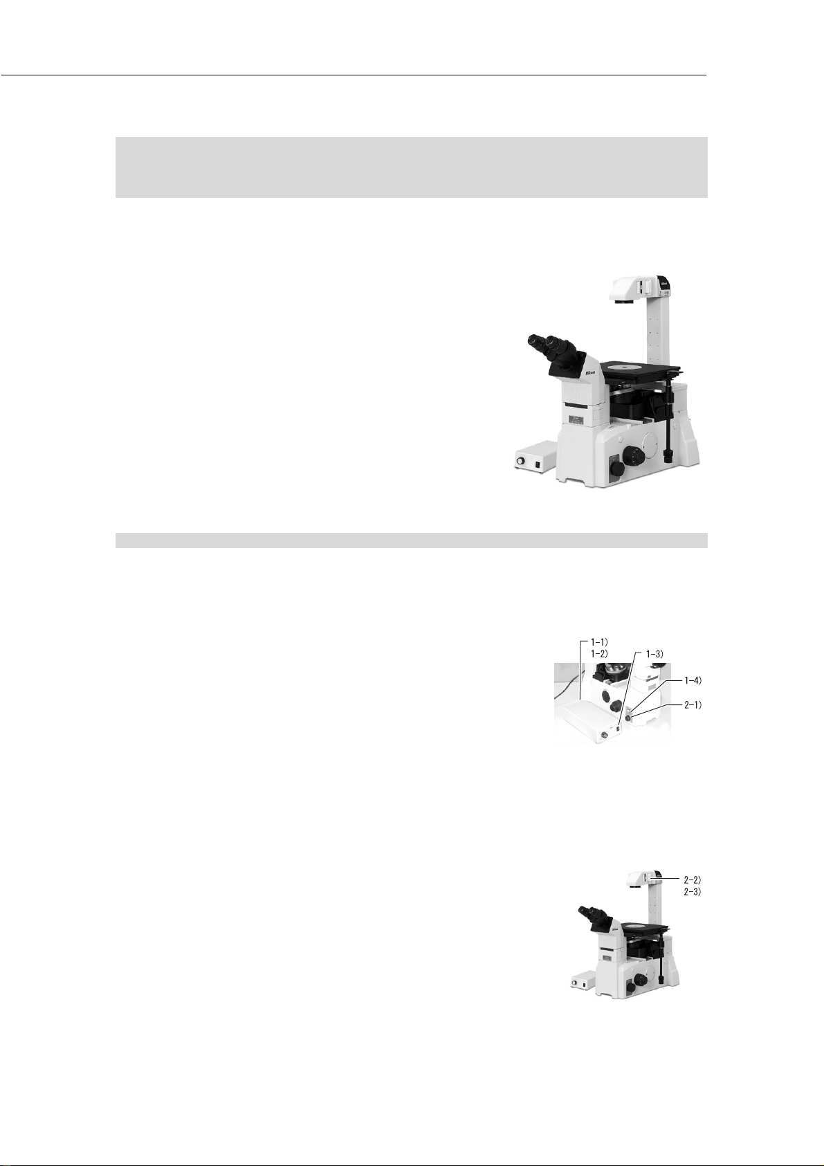
2. Microscope system consisting of TE2000-S,
”
dia-illuminator 30W, SLWD condenser,
and T-TS eyepiece tube S
The following instructions are based on a microscope equipped with the parts listed below.
TE2000-S microscope
T-TS eyepiece tube S
CFI 10X eyepiece
T-DS dia-illuminator 30W
6V30W halogen lamp
TE-PS30 power supply
SLWD condenser
T-SR rectangular stage
T-N6 sextuple nosepiece
Objectives for bright-field microscopy
Objectives for phase-contrast microscopy
Others
II. Microscopy
2-1. Bright-field (BF) microscopy
Key point: Detach all optical elements required for other types of observation from the optical path. The size of the field
diaphragm of the SLWD condenser is fixed. There is no “aperture diaphragm”.
1. Turn on the dia-illumination.
1) Make sure that the input voltage indication on the rear side
of the power supply corresponds with the voltage of the
commercial power source in the area. (-> If different, do
not turn on the switch. Contact your nearest Nikon
representative immediately.)
2) Turn on the “CTRL switch” on the rear side of the power
supply.
3) Turn on the “power switch” of the power supply. (Flip the
switch to .)
4) Press the “dia-illumination ON/OFF switch
of the microscope to turn on the lamp.
2. Adjust the lamp to ensure color fidelity.
1) Set the “brightness adjustment dial” on the left side of the
microscope to the < 6V30W > indication.
2) Move the “NCB11 filter” on the dia-illuminator into the
optical path.
3) Move the “ND4 filter” on the dia-illuminator into the optical
path.
on the left side
25
Page 28

II. Microscopy
”
”
”
”
3. Adjust the optical path.
1) Move the < 10X > objective into the optical path.
2) Set the “optical path switchover dial
microscope to position < EYE >. (-> Direct 100% of the
light to the observation port.)
3) Place a specimen on the stage.
4. Set the microscope for bright-field microscopy.
1) Slide the Ph annular diaphragm slider to move the < Open
> position into the optical path.
2) While looking into the eyepieces, turn the fine/coarse focus
knob to bring the specimen into focus.
5. Adjust the diopter and interpupillary distance.
1) Turn the “diopter adjustment rings” of both right and left
eyepieces so that the engraved line of each diopter
adjustment ring aligns with the outer ring rim of the
eyepiece. (This sets the diopter adjustment to the "0"
position.)
2) Move the < 40X > objective into the optical path.
3) While looking into the left eyepiece with your left eye, turn
the “fine/coarse focus knob
specimen into focus.
4) Move the < 10X > objective into the optical path.
5) While looking into the left eyepiece with your left eye, turn
the “diopter adjustment ring
the specimen into focus. (Do not touch the fine/coarse
focus knob on the microscope main body in this step.)
6) Repeat steps 2) through 5) two more times.
7) Adjust the right side by following the same procedure.
(Substitute "right" for "left" in steps 2) through 5), and
repeat these steps three times.)
8) Adjust the interpupillary distance to consolidate the view
fields of both eyepieces.
on the right side of the
of the microscope to bring the
of the left eyepiece to bring
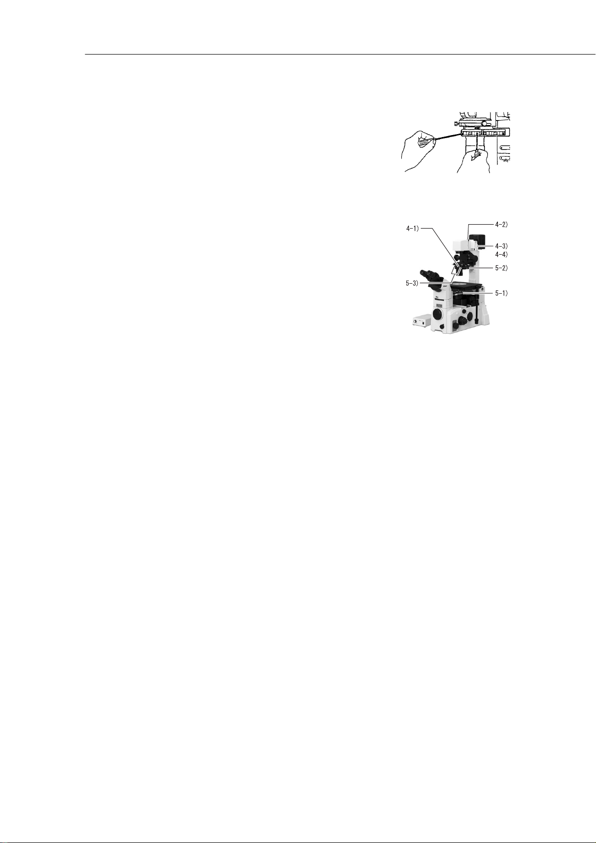
4-5)
4-8)
4-1)
Engraved
line
Diopter
adjustment ring
Outer
ring rim
4-2)
4-4)
4-3)
3-2)
6. Conduct observation.
1) Select an objective of desired magnification.
2) Move the “ND filter
on the dia-illuminator in and out of the
optical path to adjust the brightness of the view field.
Supplementary informat ion
If precise color fidelity is not required, the brightness
can be adjusted by varying the lamp voltage using the
“brightness adjustment dial” on the left side of the
microscope.
7. Upon the completion of microscopy
1) Turn off the power switch of the power supply. (Flip the
switch to {.)
2) After the lamp mounting section cools, place the vinyl cover
on the microscope.
26
Page 29
II. Microscopy
”
”
2-2. Phase-contrast (Ph) microscopy
Key point: Slide the Ph annular diaphragm slider to move the annular diaphragm with the same Ph code as the objective
into the optical path, then conduct microscopy. Note that the PhL diaphragm must be centered.
1. Focus on the specimen using bright-field microscopy.
2. Set the microscope for phase-contrast microscopy.
1) Move a Ph objective into the opt ical path.
2) Slide the Ph annular diaphragm slider to move the annular
diaphragm < with the same Ph code > as the objective
placed in the optical path in step 1) into the optical path.
3. Center the PhL diaphragm.
1) Move the < PhL > objective into the optical path.
2) Slide the Ph annular diaphragm slider to move the < PhL >
diaphragm into the optical path.
3) Remove one eyepiece, and insert the centering telescope
using the adapter.
4) Turn the eyepiece of the “centering telescope
annular diaphragm image into focus.
5) Turn the two “annular diaphragm centering screws” on the
condenser so that the annular diaphragm image coincides
with the phase plate image in the objective.
6) Reinsta ll the eyepiece to the origina l position.
to bring the
4. Conduct observation.
1) Remove the “NCB11 filter” on the dia-illuminator from the
optical path, and move the “GIF filter” into the optical path.
(-> To improve the contrast)
2) Move the “ND filter
optical path to adjust the brightness of the view field.
Supplementary informat ion
If precise color fidelity is not required, the brightness
can be adjusted by varying the lamp voltage using the
“brightness adjustment dial” on the left side of the
microscope.
on the dia-illuminator in and out of the
27
Page 30

II. Microscopy
5. Conduct observations using an objective with a different magnification value.
1) Move a different Ph objective of desired magnification into
the optical path.
2) Slide the Ph annular diaphragm slider to set to the same Ph
code as that of the objective placed in the optical path in
step 1).
6. Upon the completion of microscopy
Follow the same procedure as for bright-field (BF)
microscopy.
28
Page 31
II. Microscopy
”
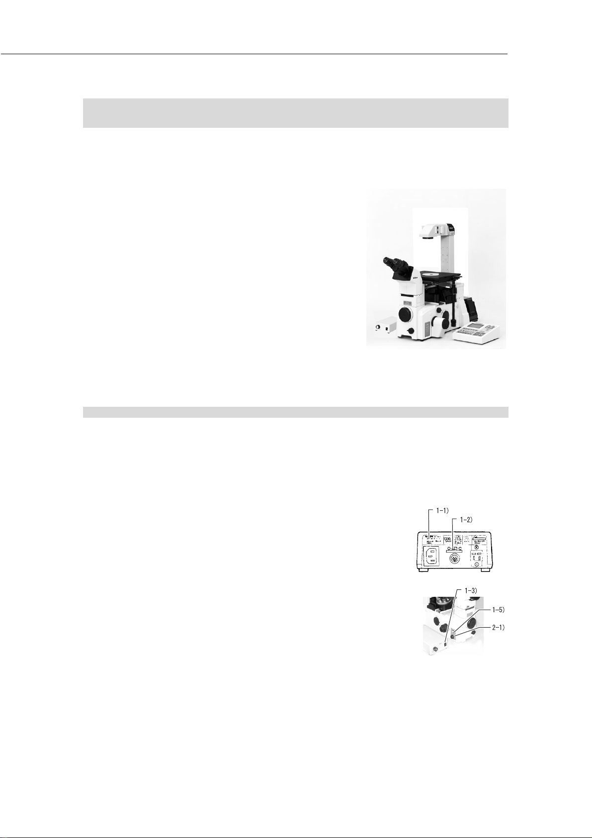
3. Microscope system consisting of TE2000-E, dia-illuminator
30W, SLWD condenser, and T-TS eyepiece tube S
The following instructions are based on a microscope equipped with the parts listed below.
TE2000-E microscope
T-HUBC HUB controller
AC adapter
Power cord for AC adapter
T-RCP remote control pad
T-TS eyepiece tube S
CFI 10X eyepiece
T-DS dia-illuminator 30W
6V30W halogen lamp
TE-PS30 power supply
SLWD condenser
T-SR rectangular stage
T-N6 sextuple nosepiece
Objectives for bright-field microscopy
Objectives for phase-contrast microscopy
Others
3-1. Bright-field (BF) microscopy
Key point: Detach all optical elements required for other types of observation from the optical path. The size of the field
diaphragm of the SLWD condenser is fixed. There is no aperture diaphragm. Since the 6V30W lamp ON/OFF
and lamp voltage adjustment cannot be controlled using the T-RCP remote control pad, use the switch and
control on the microscope main body.
1. Turn on the dia-illumination.
1) Make sure that the input voltage indication on the rear side
of the power supply corresponds with the voltage of the
commercial power source in the area. (-> If different, do
not turn on the switch. Contact your nearest Nikon
representative immediately.)
2) Turn on the “CTRL switch” on the rear side of the power
supply.
3) Turn on the “power switch” of the power supply. (Flip the
switch to .)
4) Turn on the “power switch
switch to .)
5) Press the dia-illumination ON/OFF switch on the left side of
the microscope to turn on the lamp.
of the HUB controller. (Flip the
29
Page 32

II. Microscopy
”
”
”
2. Adjust the lamp to ensure color fidelity.
1) Set the “brightness adjustment dial” on the left side of the
microscope to the < 6V30W > indication.
2) Move the “NCB11 filter
path.
3) Move the “ND4 filter” on the dia-illuminator into the optical
path.
3. Adjust the optical path.
1) Press the “OBJECTIVE
the < 10X > objective into the optical path.
2) Press the “LIGHT PATH
100% light toward the observation port.
3) Place a specimen on the stage.
4. Set the microscope for bright-field microscopy.
1) Slide the Ph annular diaphragm slider to move the < Open >
position into the optical path.
2) While looking into the eyepieces, turn the “fine/coarse focus
knob” to bring the specimen into focus.
on the dia-illuminator into the optical
key on the remote control pad to move
key on the remote control pad to point
5. Adjust the diopter and distance between the eyepieces.
1) Turn the “photo-mask dial” on the front side of the microscope
counterclockwise to move the photo-mask into the optical
path.
2) Look into the left eyepiece with your left eye. Turn the
“diopter adjustment ring” of the left eyepiece to bring the
double crosshairs of the photo-mask into focus.
3) Look into the right eyepiece with your right eye. Turn the
“diopter adjustment ring” of the right eyepiece to bring the
double crosshairs of the photo-mask into focus.
4) Turn the “photo-mask dial” on the front side of the microscope
clockwise to remove the photo-mask from the optical path.
5) Adjust the interpupillary distance to consolidate the view fields
of both eyepieces.
Turn the diopter adjustment ring
so that the double crosshairs come into focus.
Adjust the interpupillary distance
to consolidate the view fields of both eyepieces.
30
Page 33

6. Conduct observation.
1) Press the “OBJECTIVE” key on the remote control pad to
select the desired magnification.
2) Move the ND filter on the dia-illuminator in and out of the
optical path to adjust the brightness of the view field.
Supplementary informat ion
If precise color fidelity is not required, brightness can
be adjusted by varying the lamp voltage using the
“brightness adjustment dial” on the left side of the
microscope.
7. Upon the completion of microscopy
1) Turn off the power switch of the HUB controller. (Flip the
switch to {.)
2) Turn off the power switch of the power supply. (Flip the
switch to {.)
3) After the lamp mounting section cools, place the vinyl cover
on the microscope.
II. Microscopy
31
Page 34

II. Microscopy
”
”
”
3-2. Phase-contrast (Ph) microscopy
Key point: Slide the Ph annular diaphragm slider to move the annular diaphragm with the same Ph code as the objective
into the optical path, then conduct microscopy. Note that the PhL diaphragm must be centered.
1. Focus on the specimen using bright-field microscopy.
2. Set the microscope for phase-contrast microscopy.
1) Press the “OBJECTIVE” key on the remote control pad to
move a Ph objective into the optical path.
2) Slide the Ph annular diaphragm slider to move the annular
diaphragm < with the same Ph code > as the objective
placed in the optical path in step 1) into the optical path.
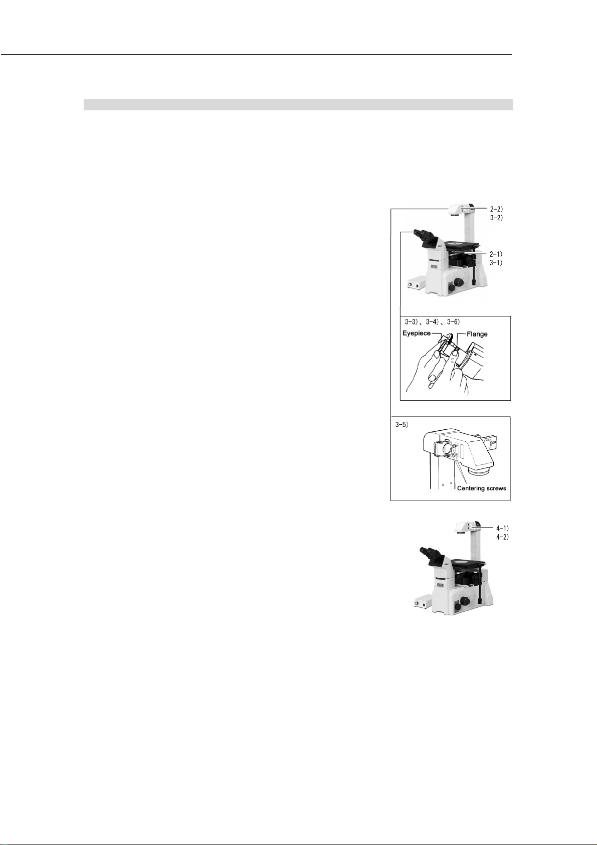
3. Center the PhL diaphragm.
1) Press the “OBJECTIVE” key on the remote control pad to
move a PhL objective into the optical path.
2) Slide the Ph annular diaphragm slider to move the < PhL >
diaphragm into the optical path.
3) Remove one eyepiece, and insert the “centering telescope
using the adapter.
4) Turn the eyepiece of the “centering telescope” to bring the
annular diaphragm image into focus.
5) Turn the two “annular diaphragm centering screws
condenser so that the annular diaphragm image coincides
with the phase plate image in the objective.
6) Return the eyepiece to the original position.
on the
4. Conduct observation.
1) Remove the “NCB11 filter
optical path, and move the “GIF filter” into the optical path.
(-> To improve the contrast)
2) Move the “ND filter” on the dia-illuminator in and out of the
optical path to adjust the brightness of the view field.
Supplementary informat ion
If precise color fidelity is not required, the brightness
can be adjusted by varying the lamp voltage using the
“brightness adjustment dial” on the left side of the
microscope.
on the dia-illuminator from the
32
Page 35

5. Conduct observations using an objective with a different
magnification value.
1) Press the “OBJECTIVE” key on the remote control pad to
move a different Ph objective of desired magnification into
the optical path.
2) Slide the Ph annular diaphragm slider to set to < the same
Ph code > as that of the objective placed in the optical path
in step 1).
6. Upon the completion of microscopy
Follow the same procedure as for bright-field (BF) microscopy.
II. Microscopy
33
Page 36

II. Microscopy
4. Photomicrography (using a 35-mm camera mounted on the
front port)
The following describes the procedure for taking pictures with a daylight-type color film using a single-lens reflex camera
attached to the front port of the microscope. Regarding the operation of the camera, refer to the instruction manual
supplied with the camera. Load the camera with film before starting the following steps. Also refer to "14.
Photomicrography" in "III. Operation of each part."
The following instructions are based on a microscope equipped with the parts listed below.
TE2000-U microscope
T-TD eyepiece tube D
CFI 10X eyepiece
T-DH dia-illuminator 100W
LHS-H100P-1 12V100W lamphouse
12V100W halogen lamp
TE2-PS100W power supply
System condenser
LWD condenser lens
Condenser module for bright-field microscopy
Condenser module for phase-contrast microscopy
T-SR rectangular stage
T-N6 sextuple nosepiece
Objectives for bright-field microscopy
Objectives for phase-contrast microscopy
Others
1. Focus on the specimen using bright-field (BF) microscopy.
2. Set up the 35-mm camera.
1) Mount the 35-mm camera on the front port.
2) Set the “exposure mode” of the camera to < Aperture
Priority Auto Mode >.
3) Set the “exposure compensation” of the camera to < +2/3
>. (-> Slight overexposure produces better results when
using a 35-mm film camera mounted on the front port.)
4) Adjust the other settings (ISO value, photometry mode,
etc.) on the camera.
34
Page 37

3. Adjust the lamp for color fidelity.
”
T
”
1) Set the “brightness adjustment dial” on the left side of the
microscope to the < 12V100W > indication.
2) Move the “NCB11 filter” on the dia-illuminator into the
optical path.
3) Move the “ND4 filter
path.
Supplementary informat ion
If precise color fidelity is not required, such as when
monochromic film is used, the “brightness adjustment
dial” on the left side of the microscope can be set to any
position.
In the case of the “
the brightness adjustment dial to < 6V30W > and
moving the “NCB11 filter” into the optical path results in
optimum color fidelity.
4. Point the optical path toward the camera.
Set the “optical path switchover dial
microscope to position < 4 >. (-> 20% light to the
observation port and 80% light to the front port)
Supplementary informat ion
When the photographing device is attached to any port
other than the front port, distribute light to that port.
on the dia-illuminator into the optical
-DS dia-illuminator 30W”, setting
on the right side of the
II. Microscopy
5. Decide on the picture composition and focus on the film
surface.
1) Turn the “photo-mask dial” on the front side of the
microscope counterclockwise to move the photo-mask into
the optical path.
2) Turn the “fine/coarse focus knob” on the microscope to
bring the specimen into focus.
Supplementary informat ion
Setting the “eyepiece tube turret” to position < M >
facilitates the focusing process. Take care not to touch
the “diopter adjustment ring” of the eyepiece in this
step.
3) Adjust the position of the specimen so that the target area
is located within the photo frame.
4) Move the “field diaphragm lever” on the dia-illuminator so
that the field diaphragm image is slightly larger than the
photo frame.
Supplementary informat ion
The TE2000-S is not equipped with a photo-mask.
Look into the finder of the photographing device to
confirm the photographing range and focus.
Installation of the optional “mask eyepiece” enables
you to see the approximate photographing range and
focus on the film using the eyepiece.
Photo frame on photo-mask
For digital camera
on the front port
with T-BFA F-mount
adapter (1X)
For 35-mm single-lens
reflex camera
on the front port
with T-BSLR SLR
camera adapter (2.5X)
For digital camera
on the front port
with T-BDCA direct
C-mount adapter (2.5X)
View field of the mask eyepiece
PL2X (35-mm full size)
PL2.5X (35-mm full size)
PL2.5X (35-mm half size)
PL4X (35-mm full size)
PL5X (35-mm full size)
35
Page 38

II. Microscopy
6. Adjust the brightne ss.
1) Move the “aperture diaphragm lever” on the condenser to
adjust the image contrast, depth of focus, and resolution.
2) Check the camera exposure time.
Longer than < 1/8 s > -> Acceptable
< 1/8 s > or shorter -> Move the “ND filter” on the dia-
illuminator in and out of the optical path to set the exposure
time to longer than < 1/8 s >. (-> To minimize the effect of
vibration caused by shutter operation)
Supplementary informat ion
If precise color fidelity is not required, such as when
monochromic film is used, the brightness may be
reduced by using the “brightness adjustment dial” on
the left side of the microscope.
7. Prevent the entry of extraneous light.
1) Set the “eyepiece tube turret” to position < C >.
2) Install the finder cap to the camera finder or cover the
finder with a cloth.
Supplementary informat ion
If an eyepiece tube turret is not included, place a cloth
on the eyepieces to prevent the entry of extraneous
light.
8. Press the shutter.
Using a remote release or self-timer of the camera eliminate s
the effect of vibration caused by shutter operation.
36
Page 39

III. Operation of each part
III. Operation of each part
In this chapter, operation of each part is described.
• Refer to “II. Microscopy” for the procedures on microscopy.
• If your microscope is not assembled yet, see “IV. Assembly” first.
• If you have mounted the Epi-fl or DIC attachment on the microscope, also refer to the instruction manual
supplied with the attachments.
• Also refer to “I. Parts of the microscope and their names” for simple description of each part.
• If you are using the TE2000-E model, read the instruction manual supplied with the T-HUBC
HUB controller.
• When the T-HUBC HUB controller is mounted on the rear side of the microscope, read the
instruction manual supplied with the HUB controller.
Before using the instrument, read the “ ”, “ ” and “Notes on handling the
microscope” at the beginning of this manual and be sure to follow the warnings and cautions written
therein.
Also refer to the instruction manual supplied with the other instruments used together with the
microscope (such as Epi-fl or DIC attachments) and be sure to follow the warnings and cautions
written therein.
37
Page 40

III. Operation of each part
|
1. Power ON / OFF
Combination of the lamp, dia-illuminator and power supply
The combination of the dia-illuminator and the power supply is fixed against the ratings of the lamp to be used (either
12V100W or 6V30W). See the chart below to check the correct combination of the lamp, dia-illuminator and the power
supply.
No other combination can be used.
To control the lamp ON/OFF and lamp voltage adjustment from the remote control pad or PC via the T-HUBC HUB controller,
be sure to use the 12V100W lamp. The 6V30W lamp cannot be controlled using the remote control pad or PC.
Microscope
TE2000-
TE2000-E
TE2000-U
TE2000-S
Ratings
of the lamp
12V100W
Halogen lamp
OSRAM HLX 64623
or
PHILIPS 7724I
6V30W
Halogen lamp
PHILIPS 5761
Dia-illuminator
T-DH 100W
( LHS-H100P-1
12V100W lamphouse
is needed)
T-DS 30W
Power supply
On 100-120V areas On 220-240V areas
TE2-PS100W
(For 100-240V areas)
TE-PS30
(For 100-120V areas)
The remote control pad and PC cannot be used to
control the lamp ON/OFF and lamp voltage
adjustment.
TE-PSE30
(For 230V areas)
Power ON / OFF
There is a “power switch” at the front of the power supply.
Pressing the switch to “ | side” will turn ON the power. The pilot
lamp lights to show the power ON status. (If TE-PS30 or TE-
PSE30 power supply is used, the power switch itself lights
instead of a pilot lamp.) Dia-illumination can now be turned on
and off by the Dia-illumination ON / OFF switch on the side of the
microscope.
Pressing the power switch to “O side” will turn OFF the lamp and the
pilot lamp (or the switch itself).
* When the T-HUBC HUB controller is mounted on the
rear side of the microscope, be sure to read the
instruction manual supplied with the HUB controller.
Power switch
: On, O:Off
Dia-illumination ON / OFF
switch
38
Page 41

III. Operation of each part
2. Brightness adjustment
Brightness can be adjusted by ND filters (dimming filters) and/or the brightness adjustment dial.
Adjustment with ND filters
Filters that control light quantity are called ND filters. An ND
filter with a large number allows less light to pa ss and therefore
produces a darker image.
Since the ND filters will not change the tint (color temperature) of
the light source, they can be useful when color reproducibility is
of concern (such as when taking pictures using day-light type
color film.)
ND filters are to be set on the filter holders on the dia-illuminator.
ND2: Reduces light quantity to 1/2
ND16: Reduces light quantity to 1/16
ND filters
Adjustment with brightness adjustment dial
There are two brightness adjustment dials: one on the front of the power supply and the other on the left side of the
microscope base. Turning the dial changes the voltage supplied to the lamp, which changes the brightness and the hue of
the illumination.
To make the illumination bright, turn the dial to larger number which results in giving the bluish hue to the illumination. To
make the illumination dar k, turn the dial to smaller number which results in giving the reddish hue to the illumination.
On normal use, set the dial between 6 to 12.
If the color reproducibility is of concern (such as when taking pictures using day-light type color film), set the dial to the
same indication as the ratings of the lamp and place the NCB11 filter in the optical path. The illumination will then become
most similar to the white light. (*1)
Two dials cannot be used simultaneously. Select which dial is to
be used with the “EXTENAL switch (or CTRL switch)” on the rear
of the power supply. (*2)(*3)
*1: In this case, brightness adjustment should be performed
with ND filters.
*2: “EXTERNAL switch” is for TE2-PS100W power supply.
“CTRL switch” is for TE-PS30 or TE-PSE30 power supply.
*3: Note that the actual brightness differs slightly between the
same numbers on the brightness adjustment dial of the
power supply and the brightness adjustment dial of the
microscope.
• When the TE2-PS100W power supply is connected to
the T-HUBC HUB controller, be sure to refer to the
instruction manual supplied with the HUB controller.
EXTERNAL switch (CTRL switch)
Set to ON
to use the brightness
adjustment dial on the
microscope.
Set to OFF
to use the brightness
adjustment dial on the
power supply.
39
Page 42
III. Operation of each part
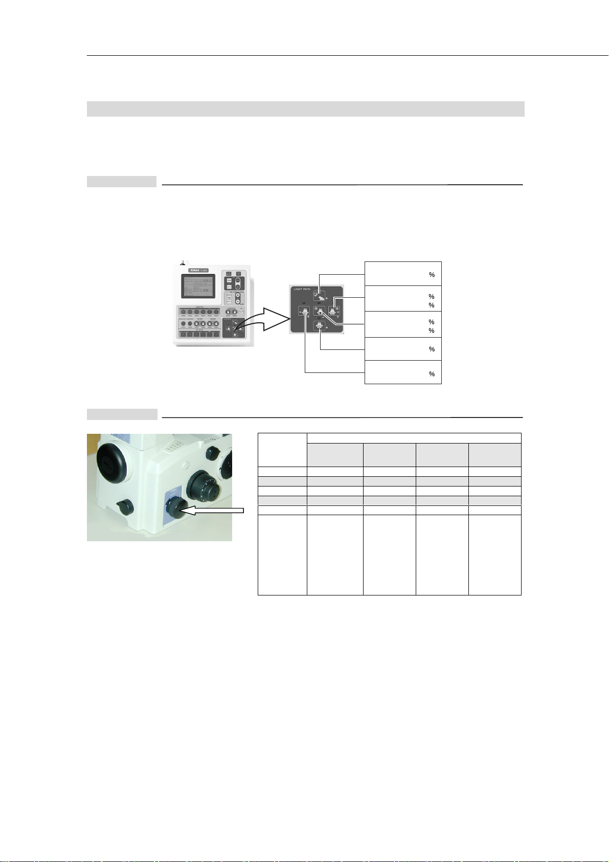
3. Optical path switching
Use the “optical path switchover dial” to send the image to each port. (See page 51 for the type of the photomicrography
equipment that each port can accept.)
For TE2000-E
Connect the T-RCP remote control pad or PC to the T-HUBC HUB controller for the switching of the optical path. For details,
refer to the instruction manual supplied with the T-HUBC HUB controller.
When using the T-RCP remote control pad
For TE2000-U
*1: Dial position "3" cannot be used on
normal microscope models; however,
an optional prism such as "front port
100%" and "right-side port 100%" can
be installed.
Observation port
Observation port
Right-side port
Observation port
Front port
Bottom port
Left-side port
100
20
80
20
80
100
100
The LED above the selected key lights.
Position of
optical path
switchover
dial
1 100 - - 2 20 - 80 -
3 (*1) - - - -
4 20 80 - 5 - - - 100
Equipment
that can be
attached to
the port
Observation
port
Eyepiece tube
Intermediate
Tub e
+
trinocular
eyepiece tube
(+ various
equipment)
Light distribution(%%%%)
Front
port
SLR camera
F-mount
digital camera
Right-side
Photomicro-
equipment
microscopes
Digital camera
TV camera
port
graphy
for
Left-side
port
Photomicro-
graphy
equipment
for
microscopes
Digital camera
TV camera
40
Page 43

III. Operation of each part
For TE2000-U Bottom port type
To open the optical path to the bottom port, pull out the bottom port changeover lever provided on the left-hand side. To
use this port, set the optical path switchover dial to position "3" and pull out the bottom port changeover lever.
Bottom port changeover lever
When the bottom port changeover lever is pulled out, the optical path is switched from the observation port to the bottom
port. If the bottom port is not used, be sure to press in the bottom port changeover lever. The optical paths to any other
ports can be switched in the same manner as for the TE2000-U.
For TE2000-S
Position of
optical path
switchover dial
SIDE 20 80
EYE 100 -
Equipment that can be
attached to the port
trinocular eyepiece
Light distribution(%%%%)
Observation
port
Eyepiece tube
Intermediate tube
+
tube (+ various
equipment)
Left-side port
TV camera
41
Page 44

III. Operation of each part
4. Using filters
Set the appropriate filters on four filter sliders of the dia-
illuminator. The following filters are available.
Filter Description
ND2
ND16
NCB11
GIF
HA
For brightness adjustment in normal microscopy and photomicrography.
Reduces light quantity to 1/2. (Approx. 50% transmissivity.)
For brightness adjustment in normal microscopy and photomicrography.
Reduces light quantity to 1/16. (Approx. 6% transmissivity.)
For correcting the color temperature in normal microscopy and color photomicrography using day-light type
color film. (Should be removed on monochrome photomicrography.)
Color reproduction is optimized when this filter is set in the optical path and the brightness adjustment dia l is
turned to the indication same as the ratings of the lamp.
Green interference filter. For microscopy using monochromatic light and for improving the contrast in
monochrome photomicrography.
Heat absorption filter. For reducing the influence of heat rays in the illumination against specimen. Though
the dia-illuminator has a built-in heat absorption filter, set this filter in the optical path if your specimen is very
sensitive to heat.
Any filter
5. Using field diaphragm
The field diaphragm restricts the illumination on a specimen to
an observed area. Raising the field diaphragm lever to its
uppermost position will maximize the diameter of the diaphragm.
(*1)
For general use, the diaphragm should be set slightly larger than
the view field. Too wide an illuminated area gives off stray light,
which causes flares, resulting in reduced image contrast.
Therefore, for photomicrography in particular, correct
adjustment is very important. The best results can be obtained
by stopping down the diaphragm so that it is slightly wider than
the area to be imaged on the film (such as the frame on the
photo-mask). (Note that stopping down the diaphragm too far
causes vignetting.)
*1: The size of the field aperture diaphragm on “T-DS dia-
illuminator 30W” is fixed and cannot be changed.
Field
diaphragm
lever
42
Page 45

III. Operation of each part
6. Using condenser aperture diaphragm
The condenser aperture diaphragm adjusts the numerical
aperture (N.A.) of the illumination system.
Aperture of this diaphragm determines optical resolution,
brightness, contrast, and depth of focus. Narrowing down the
condenser aperture diaphragm decreases resolution and
brightness, and increases contrast and depth of focus. Because
these characteristics are interrelated and cannot be controlled
one by one, the aperture must be adjusted for each specimen
and application.
Adjustment of the condenser aperture diaphragm is especially
important for bright-field microscopy, DIC microscopy, and
photomicrography. Generally, aperture settings of 70 to 80% of
the objective N.A. yield good images of appropriate contrast.
Adjust the aperture while observing the diaphragm image.
Moving the lever to the left stops down the diaphragm. Moving
the lever to the right opens it. Adjust so that the diaphragm
reaches 70 to 80% of the exit pupil of the objective.
Condenser
aperture
diaphragm
lever
•••• T-TD eyepiece tube D or T-TERG ergonomic eyepiece tube:
Turn the eyepiece tube turret to “B” to move the Bertrand lens into the optical path. Turn the Bertrand lens
focusing scre w to observe an image of the objective’s exit pupil (bright circle) and the aperture diaphragm.
Objective pupil
Aperture
diaphragm image
Turn to “B”.
70 80
100
•••• Other eyepiece tubes:
Remove one eyepiece and insert the “centering
telescope” with an adapter. Turn the eyepiece part of
the centering telescope to focus on the exit pupil of the
objective (bright circle) and the aperture diaphragm
image.
• When performing Ph microscopy with system condenser, be sure to fully open the aperture diaphragm. (If the aperture
diaphragm is stopped down, the optical path will be obstructed.)
• The aperture diaphragm on “ELWD-S condenser” works only on position A (for bright-field microscopy) and has no effect
on other positions (for Ph microscopy).
• There is no aperture diaphragm on “SLWD condenser”.
43
Page 46
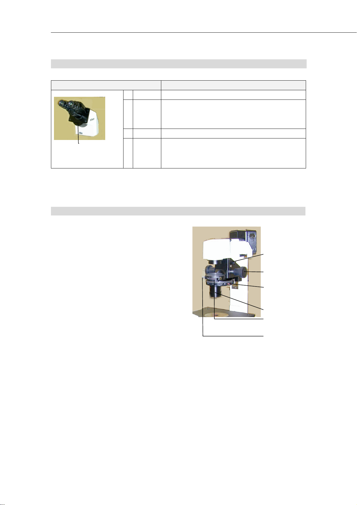
III. Operation of each part
T
7. Eyepiece tube turret
Position of the turret Description
OEmpty
The exit pupil of the objective can be observed. Turn the Bertrand
Bertrand
B
lens
C Shutter Shuts out extraneous light entering the eyepieces.
Eyepiece tube
turret
• There is no eyepiece tube turret on “T-TS eyepiece tube S” and “T-TI intermediate tube”.
M
2.5X
magnifier
lens focusing screw to focus on the exit pupil.
If manipulator is used, this lens can also be used to observe the tip
of the manipulator located just above the objective.
Applies 2.5x intermediate magnification only to the image seen
through the eyepieces. Useful when slight enlargement is
necessary or when performing focusing for photomicrography
using 4 to 20X objective. (Not equipped on T-TERG ergonomic
eyepiece tube.)
8. System condenser
A condenser has dual functions. It condenses light, and
provides the condensed light with optical elements to enable
various types of microscopic applications
Traditional microscopes require condensers to be changed
according to microscopic applications; for example, a Ph
condenser for Ph microscopy, and a DIC condenser for DIC
microscopy.
The system condenser of this microscope features modules that
contain the optical elements. Up to five modules can be
incorporated into the unit. As a result, the user needs only to
rotate the turret in order to execute various microscopic
applications, without changing condensers.
Modules can be arranged freely in the turret if they are applicable
to the condenser lens in use (there are 2 types of condenser
lenses). Modules may be replaced without dismounting the
condenser turret unit from the microscope, enabling several
microscopic applications to be executed for a short period of
time.
• For Ph microscopy, select the module having the same Ph code as marked on the objective. Bring it into the optical path
and center the annular diaphragm. Be sure to keep the condenser aperture diaphragm fully opened or the optical path
will be obstructed by the diaphragm.
• When using the T-CT-E motorized condenser turret, be sure to refer to the instruction manual supplied with the T-HUBC
HUB controller.
Condenser
refocusing clamp
Condenser focus
knob
urret and
condenser
module
Condenser lens
Aperture
diaphragm lever
Condenser
centering screw
44
Page 47

•••• Specifications of the condenser lenses
LWD condenser lens ELWD condenser lens
N.A. 0.52 0.3
Working distance 30 mm 75 mm
Available microscopy BF, Ph, DIC BF, Ph
For BF: “A”
Usable condenser modules
Others
For Ph: “PhL”, “Ph1”, “Ph2”, “Ph3”
For DIC: “DIC L”, “DIC M”, “DIC H”
For HMC: “MC1”, “MC2”, “MC3”
* Condenser refocusing clamp can be used.
* Supplementary lens is not used with this
microscope.
9. Objectives
Ph objectives
III. Operation of each part
For BF: 「A」
For Ph: “PhL”, “Ph1”, “Ph2”
A Ph objective is labeled with a Ph code: PhL, Ph1, Ph2 or Ph3.
For Ph microscopy, use the annular diaphragm (condenser module) that has the same Ph code as the objective, regardless
of the magnification of the objective.
Objective with correction ring
An inverted microscope is frequently used to observe specimens through the bottom plate of a laboratory dish or culture
bottle made of glass or plastic. For such applications, the normal objectives (for 0.17 mm thick cover glass) may not
provide clear images, disabling the microscope from demonstrating its full performances. In such cases, use an objective
with a correction ring to compensate for bottom plate thickness.
Since the objectives with correction rings are not intended to compensate for wedge-like changes of thickness at edges of
a container, we recommend that they should be used for compensation for even thickness.
•••• Adjusting the correction ring
1) Turn the correction ring to match the bottom plate thickness of the container. The thickness should be a
measured value or the value stated by the manufacturer of the container. (The acrylic stage ring is available to
improve working efficiency since it enables the part of operation to be seen from above the stage.)
2) Focus on the specimen with the focus knobs.
3) If the image has poor resolution and/or contrast, slightly rotate the correction ring clockwise or counterclockwise.
When the correction ring is rotated, the specimen image becomes slightly out of focus. Focus on the specimen
again with the fine focus knob.
4) If this has improved the resolution and contrast, rotate the correction ring further in the same direction, then
adjust the focus again.
If the resolution and contrast are deteriorated, rotate the correction ring in the reverse direction double the
amount rotated in previous turn, then adjust the focus.
In this way, rotate the correction ring in the same direction if a better image is obtained , or rotate it in this reverse
direction if a poor image is obtained. Repeat this operat ion to find the best point.
5) Taking a note of the reading of a well-visible position on the correction ring will be a help when you later use
containers having different bottom plate thickness. (The 0 mm position of the correction ring is used for
microscopy of a specimen with no cover glass on an upright type microscopes.)
45
Page 48

III. Operation of each part
Cover glass thickness
On every objective, there is a mark indicating the thickness of the cover glass to be used with. (“∞ / 0.17” means to use
a cover glass of 0.17 mm thick.) When observing with a “0.17” marked objective, place a specimen so that its cover glass
(0.17 mm thick) faces the objective. (In case of an inverted microscope, set a specimen so that its cover glass faces
down.) For an objective with a “1.2” mark, place a specimen so that its slide glass faces the objective, because the
normal slide glass thickness is 1.2 mm. (In case of an inverted microscope, set a specimen so that its cover glass faces
up.) When you observe a specimen in a laboratory dish or the like at high magnification through a glass not conforming
to the specified thickness, we recommend use of an objective that has a correction ring capable of correcting the glass
thickness error.
Oil immersion objective
The objective marked with “Oil” is an oil immersion objective.
Before using the oil immersion objective, be sure to immerse the space between the end of the objective and the specimen,
with the supplied oil (Nikon immersion oil). Use the non-fluorescent oil (option) when you carry out fluorescent
microscopy using the oil immersion objective for fluorescent microscopy.
Keep out air bubbles from the oil, since they will deteriorate visibility of images. Air bubbles may be found by observing
the exit pupil (bright circle) of the objective. (To observe the exit pupil of the objective, turn the eyepiece tube turret to
position “B” and focus with the Bertrand lens focusing screw. If your microscope does not have an eyepiece tube turret,
remove one eyepiece and insert the centering telescope with an adapter and turn the eyepiece part of the centering
telescope to focus.)
To remove air bubbles, rotate the revolving nosepiece slightly, and move the oil-immersed objective back and forth once
or twice. Or, wipe the oil off, then reapply oil to the objective.
If excessive oil is applied, surplus oil flows out and adheres to the stage or other component. Use a minimum necessary
amount of oil (enough to fill the space between the end of the objective and the specimen. Use care not to put oil to any
other components.
If oil remains on the oil immersion objective or adheres to the surface of a dry objective, it will greatly reduce image
visibility. After use, thoroughly wipe the oil off the objective surface. Also make sure that no oil has spread to the
surfaces of other objectives.
To remove oil, moisten a lens tissue or clean cloth with petroleum benzine and lightly wipe the lens surface a few times.
Use a fresh part of a lens tissue every time. For best results, wipe last with absolute alcohol (ethyl or methyl alcohol).
If you cannot obtain petroleum benzine, use methyl alcohol. Because methyl alcohol is a weaker cleaning agent, you will
need to wipe the surface repeatedly. (Usually, three or four wipes are adequate to clean the surface.)
Absolute alcohol and petroleum benzine are quite inflammable. Use great care when handling them and when setting the
power switch on and off. Be very careful with fire.
The use of acrylic stage ring (option) will facilitate the immersion operation with the culture dish left on the stage. Set the
stage ring so that its opening runs along the rim of the revolving nosepiece. Rotate the nosepiece till the objective shows
from the opening of the stage ring and hold the nosepiece there to immerse the top lens of the objective.
Water immersion objective
The objective marked with “WI” is a water immersion objective . (The one with longer working distance is for the upright
type microscopes.)
Before using the water immersion objective, be sure to immerse the space between the end of the objective and the
specimen, with the demineralized or distilled water. (Do not use the tap water for immersion since when it dries up,
impurities will stuck on the lens surface and may cause a scratch during cleaning.)
Plan Apo 60xWI objective (N.A. = 1.2) has a correction ring to compensate the difference of the cover glass thickness for
the best abberation compensation. The mark “17” on the graduation shows the position for the 0.17 mm thick cover glass.
Before using the cover glass, measure its thickness with the micrometer or the like, and set the correction ring to match
that thickness for the best compensation.
46
Page 49

III. Operation of each part
10. Diopter adjustment
Perform diopter adjustment in the following way. The adjustment corrects dioptric difference of the left and right eyes,
facilitates observation with both eyes, and reduces defocusing when changing the objectives.
For TE2000-E, TE2000-U
Turn the “photo-mask dial” on the front of the microscope counterclockwise to place the photo-mask in the optical path.
Looking into the right eyepiece with your right eye, turn the diopter adjustment ring on the right eyepiece to focus on the
double crosshairs.
Then, looking into the left eyepiece with your left eye, turn the diopter adjustment ring on the left eyepiece to focus on the
double crosshairs.
For TE2000-S
Since there is no photo-mask on TE2000-S, the diopter adjustment cannot be performed in the same way as TE2000-U
which uses double crosshairs on the photo-mask.
1) Perform steps 1 to 4 on bright field microscopy described on page 25 so that the specimen is in focus with 10x
objective.
2) Turn the diopter adjustment rings of both eyepieces to align the engraved line on each diopter adjustment ring with
the rim of the objective outer ring. (This sets the diopter adjustment to the "0" position.)
3) Bring the 40x objective in the optical path.
4) Look into the right eyepiece with your right eye. Turn the focus knob to focus on the specimen.
5) Bring the 4x or 10x objective in the optical path.
6) Look into the right eyepiece with your right eye, turn the diopter adjustment ring on the right eyepiece to focus on
the specimen. (Do not touch the focus knob at this time.)
7) Repeat steps 3) to 6) twice.
8) Do the same for the left eyepiece. (Perform steps 3) to 6) three times substituting the word “right” with the word
“left”.)
11. Focusing module
•••• When using the TE2000-U/TE2000-S:
Never turn the focus knobs on the left and right sides of the microscope in opposite directions at the same time, as
doing so can result in damage to the microscope.
Turning the coarse focus knob as far as it will go and then attempting to turn it further will result in damage to the
microscope. Never use undue force to turn the knob.
The relationship between rotation of the knobs and movement of the objective is shown below. The fine/coarse
focus knobs provide a 7-mm upward and 3-mm downward strokes from the reference position.
See the below chart for the relationship between the rotation of the focus knobs and the amount of movement.
Amount of rotation
One graduation of fine focus knob
One rotation of fine focus knob 0.1 mm
One rotation of coarse focus knob 4.9 mm
Vertical movement of
objective.
1 μm
47
Page 50

III. Operation of each part
• When using the TE2000-E:
The fine adjustment function of the focusing module of the TE2000-E is motorized, and the fine focus knob is
provided on the right side of the main body. The distance of movement achieved by one rotation of the fine focus
knob can be set to Fine, Middle, or Coarse. (The knob is set to Coarse at the factory.) The current Z-axis position
can be also displayed. For details, refer to the instruction manual supplied with the T-HUBC HUB controller.
The coarse focus knob on the left side of the main body is not motorized. Note that the coarse focus knob turns
during motorized Escape/Refocus movements. The relationship between the amount of coarse focus knob
rotation and the distance of objective movement is the same as in the TE2000-U.
Supplementary information
The distance of movement achieved by one rotation of the fine focus knob is as follows. Note that these
distances are approximate and may vary depending on the knob-turning speed. The T-EFN focus knob
functions are identical.
Fine: 25 µm/rotation
Middle: 50 µm/rotation
Coarse: 100 µm/rotation
Also note that the distance per rotation of the coarse focus knob is 4.9 mm.
Coarse focus knob torque adjustment ring (not provided on TE2000-E)
Rotating the torque adjustment ring on the left side of the microscope counter-clockwise will make the rotation of the
coarse focus knob heavy.
Objective refocusing ring (for TE2000-U only)
The objective refocusing ring on the right side of the microscope is used to mark the position of the coarse focus knob
where a specimen is in focus.
Once the refocusing ring is clamped at the in-focus position, refocusing is much easier after shifting the objective for
specimen change or other purpose. All you have to do is rotate the coarse focus knob until it reaches the limit.
The refocusing ring is useful if, for example, the objective is very close to the stage because the container of the specimen
has a thick bottom plate, and the magnification can only be changed after lowering the objective.
When the refocusing ring is not used, be sure to turn it counterclockwise till the limit to loosen the clamp. If clamped, the
focusing mechanism cannot be moved up from the clamped position with the coarse focus knob. However, stage
movement with the fine focus knob is not affected.
1) At the position where a specimen is in focus, turn the refocusing ring clockwise to clamp the ring.
2) Lower the focusing mechanism by using only the coarse focus knob, and then change the objective.
3) Raise the focusing mechanism slowly to the limit, by using only the coarse focus knob. Here, the microscope is
roughly in focus. Then, rotate the fine focusing knob to give a sharp focus.
REFOCUS/ESCAPE switch (for TE2000-E only)
The REFOCUS/ESCAPE switches at the side of the focus knob on the right side of the microscope are used to mark the
vertical position of the objective when the specimen is in focus.
Pressing the ESCAPE switch (the lower switch) lowers the objective to the Escape position (2 mm below the standard
position) while memorizing the objective position at which the switch was pressed. Pressing the REFOCUS switch (the
upper switch) will raise and return the objective to the memorized position. Use these switches to facilitate refocusing
when the objective must be lowered for specimen changes and objective switching.
48
Page 51

III. Operation of each part
T
r
p
r
r
• The fine focus knob is disabled at the Escape position.
• If the objective is at the Escape position, turning the coarse focus knob to move the objective position more than 0.5 mm
will clear the memorized position.
• Pressing the REFOCUS switch and ESCAPE at the same time will clear the memorized position.
• If the T-ND6-E sextuple motorized DIC nosepiece and the T-RCP remote control pad are also in use, automatic
Escape/Refocus movements can be set to correspond to objective switching. For detailed information, see the
instruction manual for the T-RCP remote control pad.
The coarse focus knob turns during Escape/Refocus movements.
•
coarse focus knob while these movements occur.
Turning the coarse focus knob will turn the motor set inside. On rare occasions, you may find that the coarse
•
focus knob fails to turn smoothly. This is because it engages the gear inside the motor. To restore smooth
movement, slightly turn the coarse focus knob in the opposite direction, then turn once again in the original
direction.
o prevent malfunctions, avoid contact with the
12. T-DH dia-illuminator 100W
Condenser refocusing clamp (can be used only when LWD condenser lens is attached)
After focusing the field diaphragm image on the specimen surface
using the condenser focus knob, turn the condenser refocusing
clamp clockwise to mark that position.
Even if the condenser is raised for specimen replacement, it can be
easily returned to the field diaphragm image in-focus position by
only lowering it to the limit. It is very useful when high N.A.
condenser lens is used or when the dia-illuminator cannot be tilted
for specimen replacement. The condenser refocusing clamp
works in range of 13 mm.
Condense
refocusing
clam
Rotating the condenser mount
To rotate the condenser mount, loosen the condenser mount
rotation clamp screw.
This function is mainly used for adjusting the vibration direction on
DIC microscopy.
When the system condenser is used and the polarizer is not
attached (such as when performing bright-field or Ph microscopy),
this function can be used to shift the condenser turret to the left or
right to make space for the manipulator or the other system.
Condense
mount
Condense
mount
rotation clamp
screw
49
Page 52

III. Operation of each part
Tilting the pillar
The pillar can be tilted to provide a wider operation space which will be needed when changing a large-sized specimen.
Loosen the tilting clamp screw at the rear of the illuminator and hold the front part of the illuminating section to tilt the
illuminator backward.
Usually, the tilting clamp screw can be left unlocked.
When relatively heavy device is attached to the pillar, the tilting clamp screw should be locked to avoid the pillar from
accidental tilt.
Be careful not to get your fingers caught by the moving part of the dia-illuminator when tilting it.
•
When attaching relatively heavy devices to the dia-illuminator (such as high intensity light source and its
•
adapters), be sure to fix them tightly onto the illuminator or they will fall off when the illuminator is tilted.
Screw holes for mounting various devices
There are four M4 tapped holes on the front surface of the dia-illuminator. They can be used to fix manipulator and other
devices. The upper two holes are for the devices that should be moved away from the stage when the dia-illuminator is
tilted. The lower two holes are for the devices which should remain on the stage when the dia-illuminator is tilted.
13. T-SR rectangular stage
Normally, mount the stage so that its handle comes to the rear right of the microscope. It is also possible to mount the
stage in the diagonally opposite position, with the handle at the front left. Since the universal joint is adopted on the
handle, the handle can be adjusted to any angle.
There are tapped holes on the top and bottom plates of the stage, which can be used for mounting a manipulator or other
devices.
Two types of stage rings are available: 20 mm diameter and 40 mm diameter. Use them selectively according to the sizes
of specimen containers.
If the 40 mm stage ring is used, and the stage has been moved significantly out of observation range, the objective may
strike the bottom of the stage when rotated. In this case, first lower the nosepiece to the limit and then rotate it.
The stage rack protrudes during operation. When operating the focusing knobs or the revolving nosepiece, be
careful not to graze your hand on the end of the rack.
50
Page 53

III. Operation of each part
14. Photomicrography
For details on assembly and usage of the camera and the photomicrography equipment, see the instruction manual
supplied with each equipment. Even if all microscope components are adjusted properly, you may find the image
vignetted in the finder of the camera. This has no influence on photomicrography, however.
Photomicrography equipment and ports that accept them
See the chart below for the relationship between photomicrography equipment and the port that accepts them.
Adapters need
Photomicrography equipment
Digital still cameras
(F-mount)
that have “aperture opening
priority auto mode (A)” such
as D1X, D1H, D1, etc.
35mm SLR camera
(F-mount)
that have “aperture opening
priority auto mode (A)” such
as FM3A, FE10, FE2, FE, F100,
F90, F70, F801 series, F601
series, F501, F5, F4, F3, etc.
Digital still camera
for microscopes
DXM1200, DN100, etc.
Photomicrographic equipment for
microscopes
U-III, H-III, P-III, etc.
Port that
accepts them
Front port
Front port
Front port
Side port
Bottom port
Side port
Observation port
(and its
intermediate
magnifi-
cation)
T-BFA F-mount
adapter (1X)
T-BSLR SLR
camera adapter
(2.5X)
T-BDC A dir ect Cmount adapter
For side port:
T-BPA pho to
adapter
For observation
port:
Attach to the
vertical tube of
the trinocular
eyepiece tube of
the upright
microscopes,
mounted on the
intermediate
tube
Others
Set the intermediate magnification dial
to "1.5X." If it is set to "1X," the edges of
the view field become darker.
Needs PLI projection lens.
When attached to TE2000-S, use of
“photo-mask eyepiece” will enable
focusing through eyepiece.
When attached to the side port, the cover
of the polaroid / 35mm camera back will
not open fully.
The rectangular photo-mask (not
equipped on TE2000-S) shows the range
to be taken on photo when PLI 2.5X is
used. When other PLI lenses are used,
check the range through the finder on
the photomicrographic equipment.
51
Page 54

III. Operation of each part
Photomicrography procedure and items to be checked
On photomicrography, it is especially important to obtain appropriate illumination and focus the microscope properly.
First adjust the microscope for usual observation. Then, check and perform the following
Perform diopter
1
adjustment.
Adjust illumination.
2
Eliminate uneven
illumination.
Switch the optical
3
path
4 Check the trimming.
Focus on the film
5
surface.
Shut out the
6
extraneous light.
Eliminate the
influence of
7
vibration.
8 Make exposure.
For TE2000-E, TE2000-U:
For TE2000-S: Switching between 10x and 40x objective, use focus knob and diopter
Lamp voltage: For color photomicrography, set to the same indication as lamp ratings.
Filters: For color photomicrography, set NCB11 filter in the optical path.
Condenser: Perform focusing and centering of the condenser (if T-DH dia-
Camera: “+2/3” exposure adjustment will have good results when 35mm SLR
Use the optical path switchover dial, remote control pad, or PC to guide the image to the
port on which the photomicrography equipment is attached.
(If this results in sending 100 % light to the specified port, you will need to switch back to
the observation port frequently.)
For TE2000-E, TE2000-U:
For TE2000-S: Attach the “mask eyepiece” instead of an eyepiece and check, or look
For TE2000-E, TE2000-U:
For TE2000-S: Focus on the specimen while looking through the finder on the camera
If objective with correction ring is used, check the settings of the correction ring.
Field diaphragm: Close down to a size slightly larger than the photo frame.
Eyepieces: Turn the eyepiece tube turret (not equipped on T-TS eyepiece tube S
Finder on camera or photomicrography equipment:
If exposure time is shorter than “1/8s”, insert ND filters in the optical path to make the
time longer than “1/8s”.
(If monochromatic film is used, you can also use lamp voltage to darken the image.)
Use release or self-timer of the camera.
Rotate the diopter adjustment rings so that both the photo-mask and
the specimen is in sharp focus.
adjustment rings in turn. (See page 47 for details.)
Add color compensation filters if necessary.
illuminator 100W is used).
On Ph microscopy, perform annular diaphragm centering.
Aperture diaphragm is to be set to 70 to 80% of objective N.A. on
normal use, and to be opened fully on Ph observation with system
condenser.
camera is attached to the front port.
Use the photo-mask.
through the finder on the camera or photomicrography equipment.
Turn the focus knob so that both the photo-mask and the specimen
image is in sharp focus. When using 4 to 40x objective, turn the
eyepiece tube turret (not equipped on T-TS eyepiece tube S or T-TI
intermediate tube) to “M” to enlarge the image on eyepiece only, and
focus precisely. (Do not touch the diopter adjustment ring after
turning the eyepiece tube turret to “M”.)
or photomicrography equipment, or through mask eyepiece.
or T-TI intermediate tube) to “C”. Or, cover the eyepieces with a
piece of cloth.
Cover the finder with a piece of cloth or a finder cap. (Always leave
the cover on, unless required to look into the finder.)
52
Page 55

III. Operation of each part
Photo-mask and the range to be taken on photo
(Photo-mask is not equipped on TE2000-S.)
Turning the photo-mask dial counter-clockwise will bring photo-mask in the optical path. The phot o-mask can be used for
diopter adjustment or trimming on photomicrography.
For digital camera
on the front port
with T-BFA F-mount adapter (1X)
For 35mm single-lens reflex camera
on the front port
with T-BSLR SLR camera adapter
For digital camera
on the front port
with T-BDCA direct C-mount adapter
2.5X
2.5X
Mask eyepiece and the range to be taken on photo
Remove one eyepiece and insert the “mask eyepiece” instead. This will enable trimming for photomicrography from the
binocular part of the microscope even with TE2000-S that does not have the eyepiece tube turret. It should be noted
however, that the range shown by the mask eyepiece is only a rough guide. If precise trimming is required, look and check
through the finder on the camera or the photomicrography equipment.
The following illustration shows the range taken on photo when the photomicrography equipment is attached on the side
port. (The range differs according to the magnification of the projection lens.)
PL2X (35mm full size)
PL2.5X (35mm full size)
PL2.5X (35mm half size)
PL4X (35mm full size)
PL5X (35mm full size)
53
Page 56

IV. Assembly
IV. Assembly
• Before assembling the instrument, read the “ ”, “ ” and “Notes on handling the
microscope” at the beginning of this manual and be sure to follow the warnings and cautions written therein.
• To prevent electric shock and fire, turn off all the power switches of the system and unplug the power cords.
• Be careful not to pinch your hands or fingers during assembly.
• Scratches or fingerprints on lenses will adversely affect the image. Assemble the microscope so as not to put
scratches on the lenses.
• The microscope is a precision optical equipment. Handle carefully and do not subject it to strong shocks. (The
precision of the objectives in particular can be adversely affected even by weak shocks.)
• When using the TE2000-E
• When mounting the T-HUBC HUB controller
on the rear side of the TE-2000U
• When mounting the T-HUBC HUB controller
on the rear side of the TE-2000S
Also refer to the instruction manual supplied
with the T-HUBC HUB controller.
54
Page 57
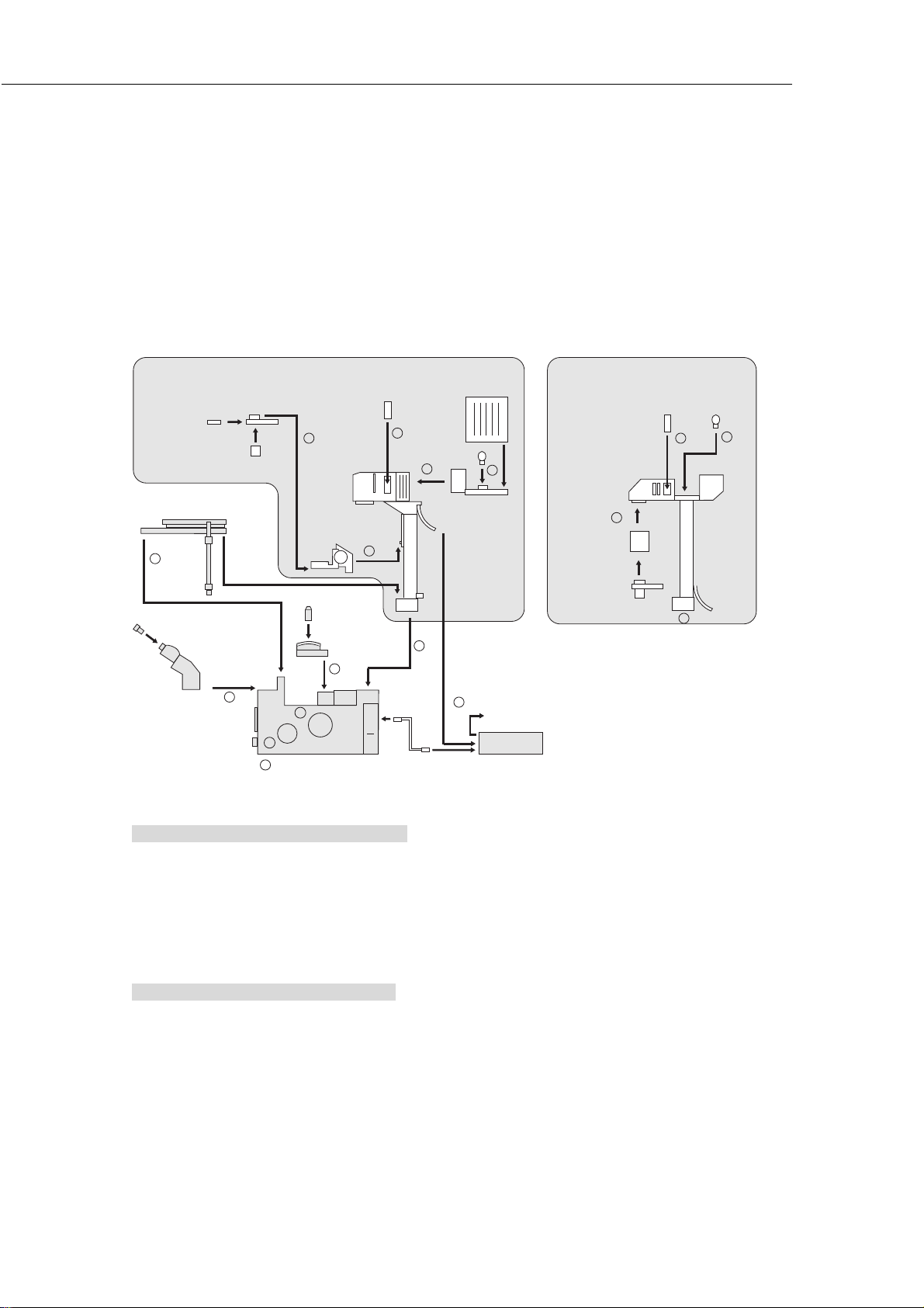
IV. Assembly
Required tools: 2mm hexagonal screwdriver x2 (supplied)
4mm hexagonal wrench x1 (supplied)
Installation location: Refer to the “Notes on handling the microscope” on the top of this manual and select an
appropriate location.
Condenser
module
Condenser
lens
Stage
6
Eyepiece
Eyepiece
tube
Combination of "T-DH dia-illuminator 100W"
and "system condenser"
Condenser
turret
2
1
8
Diailluminator
Condenser
holder
Objective
Revolving
nosepiece
3
Main body (base)
Filter
slider
5
4 -1
Lamphouse
Lamp
4 -2
4
9
Combination of "T-DS dia-illuminator 30W"
and "ELWD-S condenser"
Filter
7
To wall outlet
Power supply
slider
Diailluminator
8
Condenser
holder
Condenser
5
4
Lamp
7
Checking the power supply voltage
Make sure that the input voltage indicated on your power supply corresponds with the voltage of the
commercial power supply in your area. If the two values do not match, do not use the power supply, and
contact your nearest Nikon representative immediately. Use of a power supply with a different input
voltage indication can result in electric shock, fire, malfunction, and/or other accidents.
1. Setting the main body (base)
Take out the microscope base from the box and settle it on a stable desk.
The base is heavy. Hold it securely by the dent at the lower front and the carrying handle at the rear.
55
Page 58
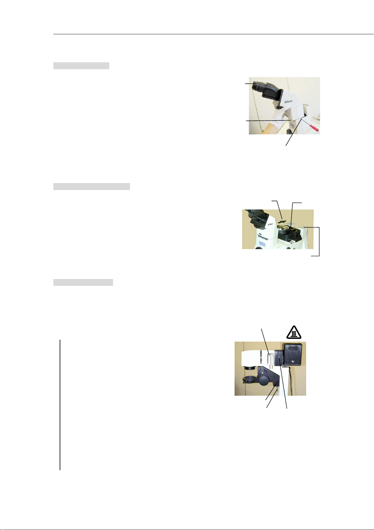
IV. Assembly
f
p
p
2. Eyepiece tube
1) Loosen the eyepiece tube clamp screw at the front of the base
using hexagonal screwdriver.
2) Remove the rubber cover.
3) Slide on the eyepiece tube from the front side till it hits the limit,
and then fix it by the clamp screw.
4) Put on the rubber cover.
5) Attach the eyepieces.
(Match 3 grooves on the eyepiece with 3 projections on the
eyepiece sleeve. The eyepieces on the right and left should be o
the same magnification. If you have rubber eye guards, put it on
the eyepieces.)
3. Revolving nosepiece
Attach the revolving nosepiece to the rectangular groove at the
center of the microscope.
Pressing the nosepiece from the front side to the rear, secure it by
two M5 hexagonal head bolts.
Screw on the objectives in an order that the magnification increases
as the nosepiece is turned clockwise when seen from above.
Eyepiece
Rubber
cover
Eyepiece tube
clamp screw
Press the nosepiece in
this direction and secure.
Dia-illuminator is set here.
Bolts
4. Dia-illuminator
Remove the carrying handle from the base.
Place the dia-illuminator oo the rear mount. Make sure that the
positioning pins on the mount fit into the holes on the illuminator.
Fix the illuminator with four M5 hexagonal head bolts supplied together.
If “T-DH dia-illuminator 100W” is to be used, do the following also.
1) Attach the condenser mount
Attach the condenser mount sliding it from the bottom to the top
along the dovetail groove. (Slide it up until it hits the limit.)
Fix the condenser mount securely with the clamp screw on the
right side.
Attach the stopper screw to the illuminator.
When using a condenser lens other than the ELWD or ELWD-S,
loosen the clamp screw, slide the condenser mount down until it
makes contact with the stopper screw, then tighten the clamp
screw firmly.
2) Attach the lamphouse
Insert the lamphouse to the top part of the dia-illuminator.
Make sure that the positioning pin on the illuminator fits into the
groove on the circular mount of the lamphouse.
Securely fix the lamphouse by the clamp screw on the right side
of the illuminator.
Caution for heat:
Do not touch while the lam
is lit or immediately after
the lamp is distinguished
Filter slider
Condenser
mount clamp
screw
Stopper screw
Lamphouse
clam
screw
56
Page 59

IV. Assembly
5. Filter slider
Attach the filters to the filter sliders. (Push aside the claw on the
circular mount when attaching the filter.)
Insert the sliders on the dia-illuminator.
6. Stage
Place the stage on the mounts at the center front of the base and the dia-illuminator.
(If your stage is equipped with the movement handle, let it position at the right rear of the microscope though it can also
be positioned at front left.)
Fix the stage with four M5 hexagonal bolt supplied together with the stage.
7. Lamp installation (lamp exchange)
• The combination of the lamp, dia-illuminator and the power supply is fixed. See page 38 and use them in
correct combination. Be sure to use the specified lamp.
• When exchanging the lamp, turn off the power and unplug the power cord to avoid electric shock.
• The lamp and its surroundings become extremely hot during lamp illumination and immediately after the
lamp is distinguished. When exchanging the lamp, turn off the lamp and wait till the lamp cools
sufficiently.
• Do not touch the lamp with bare hands. Dusts and fingerprints on the lamp surface will lead to uneven
illumination and shortening of the lamp life. Use gloves.
When using “T-DH dia-illuminator 100WWWW”:
Remove the cover of the lamphouse by loosening the clamp
screw on the right side of the cover.
Securely insert the lamp to the lamp socket till the limit while
pressing down the lamp clamp lever.
Slowly release the lamp clamp lever. Make sure that the lamp
is not tilted. If so, reattach the lamp.
Return the cover to the lamphouse and fix it by the clamp
screw.
Caution for heat:
Do not touch while the lamp
is lit or immediately after the
lamp is distinguished
Cover clamp screw
Lamp clamp lever
When using “T-DS dia-illuminator 30WWWW”:
Open up the cover at the rear part of the dia-illuminator.
Attach the lamp to the socket.
Close the cover
Caution for heat:
Do not touch
while the lamp is
lit or immediately
after the lamp is
distinguished
57
Page 60

IV. Assembly
g
”
p
8. Condenser
When “T-DH dia-illuminator 100WWWW” is used:
(Attachable condensers:
System condenser or ELWD-S condenser)
Loosen the condenser clamp screw inside the hole at the
right side of the condenser holder using hexagonal
screwdriver. (If the mount has been rotated from its
standard position, the condenser clamp screw cannot be
found inside the hole. In the case like this, loosen the
condenser mount rotation clamp screw and rotate the
condenser mount with your hand so that the positioning
groove on the mount matches the positioning pin on the
condenser holder. Tighten the rotation clamp screw at that
position.)
Attaching the “system condenser”:
1) Rotate the turret so that the module “A
for bright-field microscopy) comes int o the optical path.
2) Slide on the turret to the bottom mount of the condenser
holder so that the indication “A” faces front. Fix the
turret securely by the condenser clamp screw.
3) Insert the modules to the turret and fix each of them by
two hexagonal screws. Five modules can be attached
to the turret. Set them so that the indication on the
module increases as the turret is rotated clockwise when
seen from above.)
4) Screw on the condenser lens to the bottom of the turret.
(See page 45 for the correct combination of the module
and the condenser lens. The auxiliary lens supplied
with the LWD condenser lens is not used on this
microscope.)
Attaching the “ELWD-S condenser”:
Insert it into the bottom mount of the condenser holder so
that the turret indication faces front. Fix it securely with
the condenser clamp screw.
(hollow module
Position ing pin
Position ing
roove
Mount rotation
clamp screw
Turret
Condenser
lens
Condenser
module
Condenser clamp screw
(Deep inside the hole.)
Condenser
clam
screw
When “T-DS dia-illuminator 30WWWW” is used:
(Attachable condensers:
ELWD-S condenser, SLWD condenser or HMC
condenser)
Attaching the “ELWD-S condenser”:
1) Attach the condenser holder on the dia-illuminator.
2) Attach the ELWD-S condenser on the condenser holder.
Condenser holder
ELWD-S
condenser
58
Page 61
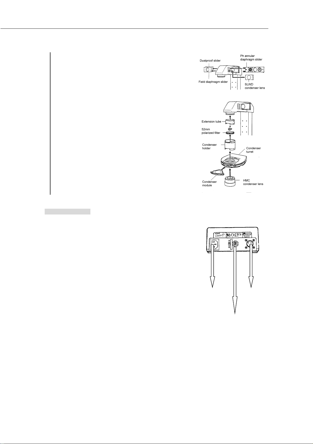
Attaching the “SLWD condenser”:
L
”
1) Remove the dustproof and field diaphragm sliders from
the illuminator.
2) Insert the SLWD condenser lens to the front, and Ph
annular diaphragm slider to the rear opening.
Attaching the “HMC condenser”:
1) Screw on the 52mm polarized filter inside the extension
tube supplied together with the HMC condenser lens.
2) Attach the extension tube to the dia-illuminator.
3) Attach the condenser holder to the extension tube.
4) Attach the condenser turret to the condenser holder.
5) Screw on the HMC condenser lens to the turret.
6) Attach the HMC module to the turret.
IV. Assembly
9. Power supply
First make sure that the power switch is turned off (pressed to the O side).
1) Lamp cable
Lamp cable of the dia-illuminator is to be connected to the
“OUTPUT” connector on the power supply. Do not forget to
tighten the lock ring on the connector.
2) Control cable
Connect one side the “LAMP CTR
and the other side to the “EXTERNAL” connector on the power
supply. (If TE-PS30 or TE-PSE30 power supply is used, connect
to “CTRL” connector instead of the EXTERNAL connector.)
When installing the HUB controller, be sure to refer to the
instruction manual supplied with the HUB controller.
3) Power cord
Connect one side to the “AC IN” connector on the power supply,
and the other side to the wall outlet.
If other devices, such as photomicrographic equipment, are to be
attached to the microscope, the power cord should be connected
only after those devices are attached to the microscope.
This ends the assembly of normal set.
connector on the microscope,
Power cord
(To the wall outlet)
Control cable
(To the “Lamp CTRL” connector on
the microscope)
Lamp cable
dia-illuminator)
(To the
59
Page 62
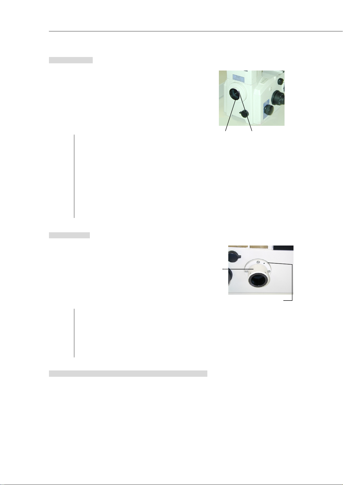
IV. Assembly
”
10. Front port
See page 51 for the photomicrography devices that can be attached
to the front port and the adapters needed.
1) Pull off the plastic cap on the front port with your hand.
2) Insert the adapter and fix it by the clamp screw.
(If the adapter has a positioning pin, match it with the
positioning groove on the front port.)
3) Attach the photomicrography device to the adapter. have
rubber eye guards, put it on the eyepieces.)
Ex.: Attaching “Digital still camera D1
adapter”
Remove the cap on the F-mount adapter. Attach the
camera to the adapter matching the index marks, and
rotate the camera in the direction shown by the arrow
on the mount (counterclockwise) till a click is heard.
Dismounting the camera:
Pressing the lens dismounting button on the camera,
slowly rotate the camera clockwise until it stops.
Note that the F-mount may be damaged if you
attempt to rotate the camera in the direction of the
arrow.
to “T-BFA F-mount
Position ing
groove
Adapter clamp
screw
11. Side port
See page 51 for the photomicrography devices that can be attached
to the side port and the adapters needed.
1) Remove the plastic cap on the side port by loosening the
clamp screw.
2) Insert the side port adapter and fix it by the clamp screw.
3) Insert the adapter to the side port adapter and fix it by the
clamp screw.
4) Attach the photomicrography device to the adapter.
Ex.: Attaching “Photomicrographic equipment U-III” to
“T-BPA photo adapter”
Insert the PLI projection lens to the “T-BPA photo
adapter” till it hits the limit. Insert the
photomicrographic equipment to the adapter so that
its finder faces forward. Fix it by tightening the
connection ring.
Side port
adapter
Side port adapter
clamp screw
12. Attaching various devices to the observation port
Remove the eyepiece tube from the microscope and attach the “T-TI intermediate tube” instead. The intermediate tube
accepts various devices such as the trinocular eyepiece tube for upright type microscopes and teaching head.
60
Page 63

V. Troubleshooting
V. Troubleshooting
If the microscope does not function properly, take appropriate action as described below. If the problem is still not
resolved after referring to “Troubleshooting,” please contact your nearest Nikon representative.
1. Optical
Symptoms Causes Countermeasures
Install the parts (nosepiece, condenser, etc.)
correctly.
Rotate the parts till the click stop position or till the
limit. (Parts such as optical path switchover dial,
nosepiece, filter sliders, condenser turret, eyepiece
tube turret and photo-mask dial.)
Perform condenser focusing and centering correctly.
Perform condenser focusing and centering correctly.
Adjust correctly.
Use container with bottom plate thickness within
correction range.
Perform condenser focusing and centering correctly.
Put the annular diaphragm that matches the Ph code
of the objective into the optical path.
Center the annular diaphragm.
Open fully.
Install correctly and rotate to the click stop position.
Install correctly and rotate to the click stop position.
Center the annular diaphragm.
Adjust the brightness adjustment dial to match the
lamp ratings.
View field
vignetting.
Uneven
brightness in the
view field.
View field not
visible.
Dirt or dust in the
view field.
Poor image
quality.
Poor contrast.
Poor resolution.
No phase
contrast effect.
(on Ph
microscopy)
Uneven focus.
Image flows.
Yel lo w is h im age .
Parts not correctly installed.
Movable parts not switched correctly.
Stage ring on the optical path. Change the specimen position.
Field diaphragm image not focused on the
specimen surface.
Field diaphragm stopped down too far. Open to slightly large a size as the view field.
Dirt or dust on lens and container. Clean them. Use clean container.
Dirt or dust on lens and container. Clean them. Use clean container.
Field diaphragm image not focused on the
specimen surface.
Dirt or dust on lens and container. Clean them. Use clean container.
Objective’s correction ring not set to the
bottom plate thickness of the container.
Bottom plate thickness of the container is
outside the correction range of the
objective.
Field diaphragm image not focused on the
specimen surface.
Bright-field objective is used. Use Ph objective.
Condenser annular diaphragm not on
optical path.
Condenser annular diaphragm not
centered.
Aperture diaphragm not fully open (when
using system condenser).
Revolving nosepiece not installed correctly,
or not rotated to the click stop position.
Specimen tilted against stage surface. Correctly reposition specimen on stage.
Revolving nosepiece not installed correctly,
or not rotated to the click stop position.
Condenser annular diaphragm not
centered.
Dia-illuminator tilted. Raise till it hits the limit.
No NCB11 filter in the optical path. Put it in the optical path.
Lamp voltage too low.
61
Page 64

V
. Troubleshooting
Symptoms Causes Countermeasures
View field too
bright。
View field too
dark.
No ND filter in optical path. Put it in the optica l path.
Lamp voltage too high. Lower the voltage with brightness adjustment dial.
Condenser aperture diaphragm stopped
down too far.
Field diaphragm image not focused on the
specimen surface.
Optical path switchover dial not set to
100% observation.
Normally, set to 70 to 80% of the objective N.A.
Perform condenser focusing and centering correctly.
Switch to 100% observation.
2. Operational
Symptoms Causes Countermeasures
Image not in
focus although
the objective is
raised to the
highest position.
Cannot focus with
20x and 40x
objective.
Images on the
left and right
eyepieces not
coincident.
Eye fatigue
Stage mounted incorrectly. Mount it correctly.
Objective refocusing ring clamped.
Bottom plate thickness of the container is
outside the correction range of the
objective.
Interpupillary adjustment not performed. Make adjustment.
Diopter adjustment not performed. Make adjustment.
Inadequate brightness. Adjust with brightness adjustment dial or ND filters.
Release the clamp by turning the ring
counterclockwise to the limit.
Use container with bottom plate thickness within
correction range.
62
Page 65

3. Electrical
Symptoms Causes Countermeasures
Power does not
turn on even
though the power
switch is set to
on.
Lamp does not
light.
Lamp burnt too
early.
adjustment dial
on the
microscope does
not work.
ON/OFF switch on
the microscope
does not work.
Brightness
adjustment dial
on the power
supply does not
work.
No focus
adjustment when
the selector
switch on the TEFN focus knob is
switched on (only
when the
TE2000-E is used)
Power cord not connected, or connected
improperly.
Lamp burnt. Replace with specified lamp.
Non-con forming lamp used. Replace with specified lamp.
Control cable not connected. Connect properly.Brightness
EXTERNAL switch on the power supply
(CTRL switch when TE-PS30/TE-PSE30 is
used) is OFF.
Lamp burnt. Replace with specified lamp.Dia-illumination
Control cable not connected. Connect properly.
EXTERNAL switch on the power supply
(CTRL switch when TE-PS30/TE-PSE30 is
used) is ON.
Knob connection cable is not connected or is
improperly connected
Connect properly.
Turn ON.
Turn OFF.
Connect the cable properly.
V. Troubleshooting
63
Page 66

VI. Care and maintenance
VI. Care and maintenance
1. Lens Cleaning
Do not let dust, fingerprints, etc., get on the lenses. Dirt on the lenses, filters, etc., will adversely affect the view of
the image. If any of the lenses get dirty, clean them as described below.
• Either brush away dust with a soft brush, or else wipe it away gently with gauze.
• Only if there are fingerprints or grease on a lens, dampen a piece of soft, clean cotton cloth, lens tissue, or gauze
with absolute alcohol (ethyl or methyl alcohol) and wipe.
• Only when removing the immersion oil off from the objective, use petroleum benzine. If you cannot obtain
petroleum benzine, use methyl alcohol. However, because methyl alcohol does not clean as well as petroleum
benzine, it will be necessary to wipe the surfaces repeatedly. (Usually, three or four times is sufficient to clean the
lenses.)
• Never use petroleum benzine to clean the entrance lens at the bottom of the eyepiece tube or orusn surface of the
eyepiece tube.
• Absolute alcohol and petroleum benzine are highly flammable. Be careful when handling it, when around open
flames, when turning the power switch on / off, etc.
• Follow the instruction s provided by the manufacturer when using absolute a lcohol.
2. Cleaning the microscope
• We recommend that you use a silicon cloth to clean the microscope.
• For persistent dirt, dampen a piece of gauze with neutral detergent and wipe lightly.
• Using organic solvents could result in discoloration of the plastic parts.
3. Disinfecting the microscope
• We recommend that you use 70% medical alcohol for normal disinfection of the microscope.
• In case of spillage of a sample onto the microscope, determine whether the sample is hazardous. If the sample is
hazardous, follow your standard laboratory procedures.
• Using organic solvents could result in discoloration of the plastic parts.
4. Storage
Store the microscope in a dry place where mold is not likely to form.
Store the objectives and eyepieces in a desiccator or similar container with a drying agent.
Put the vinyl cover over the microscope to protect it from dust.
Before putting on the vinyl cover, turn off the power switch on the microscope (flip it to the O side) and wait until the
lamphou se is cool.
5. Periodical inspections (charged)
Periodical inspections (expenses charged) of this microscope are recommended in order to maintain peak
performance. Contact your nearest Nikon representative for details.
64
Page 67

VII. Technical specifications
VII. Technical specifications
1. When the microscope (TE2000-E, TE2000-U, TE2000-S) is used in combination
with T-DH dia-illuminator 100W (for 12V100W lamp)
Combination Microscope + T-DH dia-illuminator 100W + TE2-PS100W power supply
Dimensions
Weight 41 Kg
Opto-mechanical specification
Input ratings of T-DH dia-illuminator
100W
Lamp ratings 12V100W halogen lamp
Lamp type Halogen lamp (OSRAM HLX 64623 or PHILIPS 7724I)
Average lamp lifetime 2,000 hrs.
TE2-PS100W power supply
Operating environmental conditions
Storage and transport environmental
conditions
Installation category Category II
568(W) × 727(D) × 703(H) mm
Objectives: CFI60
Eyepieces: Field Number 22
Nosepiece : 6-place
Focusing:
Stroke 10 mm
Coarse 4.9 mm/rev.
Fine 0.1 mm/rev.
Fine scale 0.05 μm (TE2000-E), 1 μm (TE2000-U,S)
DC 12 V, 100 W
Input ratings: AC 100-240 V, 50/60 Hz, 2.4 A
Voltage fluctuation: ±10%
Output ratings: DC 12 V, 100 W, 8.4 A
Built-in fuse ratings: 250 V, T4A
Protection class: Class 1
Others: UL Recognized product, GS approved
Altitude: 2,000 m max.
Temperature: 0 to 40ºC
Relative humidity: 85% max. (no condensation)
Pollution degree: Degree 2
Indoor use only
Temperature: -20 to +60℃
Humidity: max. 90% RH (no condensation)
65
Page 68

VII. Technical specifications
2. When the microscope (TE2000-E, TE2000-U, TE2000-S) is used in combination
with the T-DS dia-illuminator 30W (for 6V30W lamp)
When the supply voltage is 100 to 120 V:
Combination
Dimensions:
Weight: 37 Kg
Opto-mechanical specification
Input ratings of T-DS dia-illuminator
30W
Lamp ratings DC 6V30 W halogen lamp
Lamp Halogen lamp (PHILIPS 5761)
Average lamp lifetime: 100 hrs.
TE-PS30 power supply
TE-PSE30 power supply
Operating environmental conditions
Storage and transport environmental
conditions
Installation category Category II
Microscope + T-DS dia-illuminator 30W + TE-PS30 power supply
When the supply voltage is 220 to 240 V:
Microscope + T-DS dia-illuminator 30W + TE-PSE30 power supply
568(W) × 727(D) × 611(H) mm
Objectives: CFI60
Eyepieces: Field Number 22
Nosepiece: 6-place
Focusing:
Stroke 10 mm
Coarse 4.9 mm/rev.
Fine 0.1 mm/rev.
Fine scale 0.05 μm (TE2000-E), 1 μm (TE2000-U,S)
DC 6 V, 30 W
Input ratings: TE-PS30: AC 100-120 V, 50/60 Hz, 0.6 A
TE-PSE30: AC 230 V, 50/60 Hz, 0.4 A
Voltage fluctuation: ±10%
Output ratings: DC 6 V, 30 W
Built-in fuse ratings: 250 V, F2AH
Protection class: Class 1
Others: TE-PS30: UL Recognized product
TE-PSE30: GS approved
Altitude: 2,000 m max.
Temperature: 0 to 40ºC
Relative humidity: 85% max. (no condensation)
Pollution degree: Degree 2
Indoor use only
Temperature: -20 to +60℃
Humidity: max. 90% RH (no condensation)
66
Page 69

VII. Technical specifications
3. Specified AC adapter for use with the HUB controller (only when using the T-
HUBC HUB controller)
Manufacturer PHIHONG ENTERPRISE (Taiwan)
Type PSA30U-120 (N)
Input rating AC 100-240 V, 0.7 A, 50/60 Hz
Voltage fluctuation
Output rating DC 12 V
Rated output current 2.5 A
Others UL Listed product, GS approved, CE satisfied
±10%
4. Power cord for power supply and for AC adaptor of HUB controller
Be sure to use the following power cords.
When the supply voltage is 100 to 120 V
When the supply voltage is 220 to 240 V
UL Listed detachable cord set, 3 conductor grounding Type SVT, No. 18
AWG, 3 m long maximum, rated at 125 V AC minimum.
Approved according to EU/EN standards, 3 conductor grounding Type
HO5VV-F, 3 m long maximum, rated at 250 V AC minimum.
67
Page 70

VII. Technical specifications
5. Conforming standards
Microscope (TE2000-E,
TE2000-U,
TE2000-S) used in
combination with the TE2-PS100W
power supply or TE-PS30 power supply
UL Listed Product.
FCC 15B, Class A satisfied.
This equipment has been tested and found to comply with the
limits for a Class A digital device, pursuant to Part 15 of the
FCC Rules.
These limits are designed to provide reasonable protection
against harmful interference when the equipment is operated
in a commercial environment.
This equipment generates, uses, and can radiate radio
frequency energy and, if not installed and used in accordance
with the instruction manual, may cause harmful interference
to radio communications.
Operation of this equipment in a residential area is likely to
cause harmful interference in which case the user will be
required to correct the interference at his own expense.
This Class A digital apparatus complies with Canadian ICES-
003.
Cet appareil numérique de la classe A est conforme à la norme
NMB-003 du Canada.
* Note that the microscope will not meet the above standards if used in combination with a motorized XY stage or shutter
made by any manufacturer other than Nikon.
・ Meets EU IVD Directive (In vitro
diagnostic medical device directive)
Microscope (TE2000-E,
TE2000-U,
TE2000-S) used in
combination with TE2-PS100W power
supply or TE-PSE30 power supply
requirements.
(GM-approved: In vitro diagnostic
medical device)
・ Meets EU LV Directive (Low voltage
directive) requirements.
・ Meets EU EMC Directive requirements.
(EN61326)
* Note that the microscope will not meet the above standards if used in combination with a motorized XY stage or shutter
made by any manufacturer other than Nikon.
68
Page 71

VII. Technical specifications
Blank Page
69
Page 72

System diagram
System diagram
HMC MC1, MC2, MC3
Centering
Telescope
Y-TT Trinocular Tube TUW
Y-TF Trinocular Tube FUW
Y-IDT Drawing Tube
Teaching Heads
1
Eyepiece
Tubes
Modules
Phase PH-L, PH-1,
PH-2 Modules
Phase PH-L, PH-1,
PH-2, PH-3; DIC NL,
NM, NH; HMC MC1,
MC2, MC3 Modules
HMC Lens
ELWD Lens
LWD Lens
System Condenser
Turret
T-CT-E Motorized
Condenser Turret
Eyepiece Tube D
C-HU Universal
Holder
Acrylic Stage Ring
T-SR
Rectangular Stage
C-Mount
CCTV
Camera
C-Mount
Zoom
Adapter
ENG-Mount
CCTV Camera
T-TD
C-HT
Terasaki
Photomicrographic
System FX-III Series
Multi-image
Module
C-Mount
Adapter A
C-Mount
Adapter A
C-Mount
Adapter
0.45X, 0.6X
C-Mount
CCTV
Adapter
TV
Zooming
Lens
Adapters
T-TS
Eyepiece Tube S
C-HSG Slide
Glass Holder
T-BPA Photo
Adapter
C-Mount Adapter A
C-Mount TV
Adapter VM4X
C-Mount TV
Adapter VM2.5X
T-BPA
Relay
Photo
Lens 1X
Adapter
T-TERG
Ergonomic
EyepieceTube
Hemacytometer
Holder
T-SP Plain Stage
35mm SLR
Camera
High-definition
Digital Camera
DXM1200
C-mount TV
Camera
F-mount
Digital
Camera D1
T-TI
Intermediate
Tube
35mm Petri
Dish Holder
T-SAM
Attachable
Mechanical
Stage
T-FLBW-E BA
Filter Wheel
T-BSLR
Front-port
SLR Adapter
T-BFA Front-port
F-mount Adapter
T-BDCA
Front-port
Direct C
Adapter
2
4
3
Stages
Side
Port
Front Port
DIC NM, NH
Modules
DIC NM, NH
Modules
DIC NH, NH-SS
Modules
T-N6 Sextuple
Nosepiece
Eyepiece
Tubes
1
REFOCUS
COARSE FOCUS
ESCAPE
High N.A. Lens
(Dry)
High N.A. Lens
(Water)
High N.A. Lens
(Oil)
CFI Objectives
T-ND6 Sextuple
DIC Nosepiece
Nosepieces
T-BSUK
Stage Riser
Stages
Nosepieces
2
Attachments
6
A B
Epi-fl
8
Bottom Port
High N.A.
Condenser
Holder
High N.A. Condenser
TE-C ELWD
Condenser
DIC Slider
T-ND6-E Sextuple
Motorized DIC Nosepiece
6
Stage Riser
Illumination
Pillars
7
C
4
Lens Unit
T-BSUK
T-HUBC
Hub Controller
D
Side Port
5
T-A Analyzer
T-A-E Motorized
DIC Analyzer
T-AC
AC Adapter
T-RCP
Remote Controller
Condensers
70
Page 73
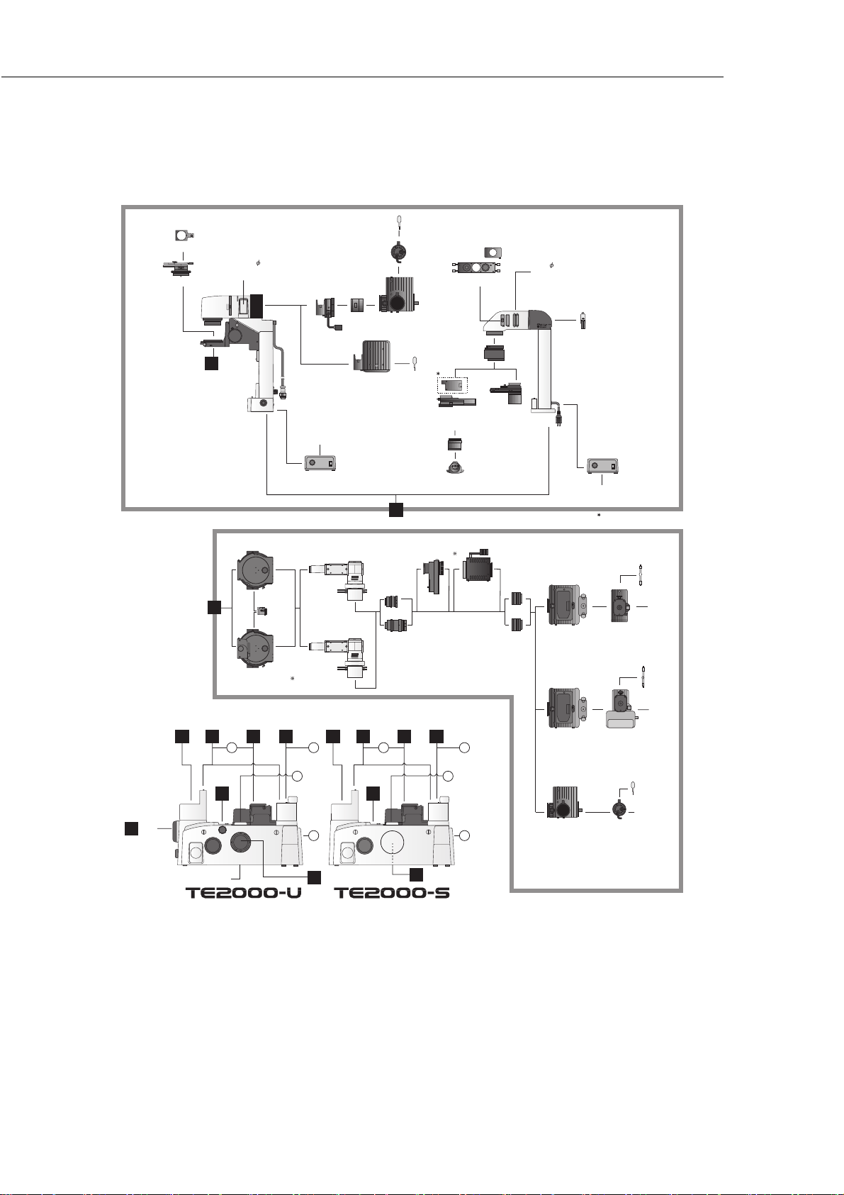
Lambda Plate
T-P Polarizer
Condensers
T-DH
Dia-illuminator 100W
Epi-fl Attachments
Eyepiece
Stages
Tubes
1
Filter 45mm;
GIF, NCB11, ND16, ND2
Heat Absorbing
5
T-FLC Cassette Holder
8
T-FLC-E
Motorized Cassette Holder
Nosepieces
6
2
A B
TE2-PS 100W
12V Power Supply for
100W Illumination Pillars
Epi-fl
Filter
Blocks
T-FL-E Epi-fl
Attachment
with
Motorized
Shutter
Illumination
Pillars
7
HMX
Lamphouse
Adapter
LHS-H100P-1 Lamphouse
Remote
Cable
T-FL
Epi-fl
Attachment
Eyepiece
Tubes
1
Collector
Lens
Illumination Pillars
FL Illumination
Adapter
Illumination
Stages
2
A B
Halogen Lamp
12V-100W
Halogen Lamp
12V-100W LL
7
T-FLA
T-FLZA
FL Zoom
Adapter
Nosepieces
6
Halogen Socket
100W
HMX
Lamphouse
System
Condenser
HMC MC1, MC2, MC3
T-FLEW-E
EX Filter Wheel
Illumination
Pillars
7
SLWD Condenser
Turret
HMC Lens
Modules
TE-AT
Double
Lamphouse
Adapter
Adapter
TE-C ELWD
Condenser
C-FC
Epi-fl
Collector Lens
Epi-fl
Collector
Lens Q2
Filter 33mm;
GIF, Heat Absorbing,
NCB11, ND16, ND2
Halogen Lamp
6V-30W
T-DS
Dia-illuminator 30W
Lamphouse
HMX-3B/HMX4B
w/Backmirror
Xenon
Lamphouse
System diagram
TE-PS 30/TE-PSE30
6V Power Supply
for 30W Illumination
Pillar
Remote
Cable
Provided with the HMC lens.
Mercury Lamp
Socket S 100W
Xenon
Lamp Socket
Marcuy
Lamp
HG-100W
Starter
HG-100W
Xenon
Lamp
Xenon
Starter
Side Port
Epi-fl
Attachments
8
4
C
D
Side Port
Epi-fl
Attachments
Front
3
Port
Model with bottom port also available
C
8
D
4
• Components not included in UL or GM approval are also shown.
• Components not described in this manual are also shown.
• This system diagram is subject to change without notice.
HMX
Lamphouse
Halogen Socket
100W
Halogen
Lamp
12V-100W
U Transformer
71
Page 74

 Loading...