

Page 1

M358 E 05.4.NF.1
ECLIPSE TE2000 INVERTED
MICROSCOPE
PERFECT FOCUS SYSTEM
T-PFB Perfect Focus Module
T-PFC Perfect Focus Controller
T-FLC2-E Motorized Cassette Holder
Instructions
Page 2

Page 3

Preface
Thank you for purchasing the Nikon products.
This instruction manual is written for the users of the Nikon’s Eclipse TE2000-E Inverted Microscope Perfect Focus
System.
To ensure correct usage, read this manual carefully before operating the instrument.
• It is prohibited to reproduce or transmit this manual in part or whole without Nikon’s expressed permission.
• The contents of this manual are subject to change without notice.
• Although every effort has been made to ensure the accuracy of this manual, if you note any points that are unclear or
incorrect, contact your nearest Nikon representative.
• Some of the products described in this manual may not be included in the set you have purchased.
• Be sure to read the instruction manuals for TE2000-E/U/S Inverted Microscope.
1
Page 4
Warning for Using this Product
WARNING and CAUTION Symbols
Although Nikon products are designed to provide the utmost safety during use, incorrect usage or failure to follow the
safety instructions provided may cause personal injury or property damage. To ensure correct use, read the instruction
manual carefully and thoroughly before using the instrument. Do not discard the manual; keep it handy for easy
reference.
Safety instructions within this manual are accompanied by the following symbols to highlight their importance. For your
safety, always follow the instructions accompanying these symbols.
Symbol Meaning
WARNING
CAUTION
Disregarding instructions accompanying this symbol may lead to serious injury or death.
Disregarding instructions accompanying this symbol may lead to injury or property
damage.
2
Page 5
Warning for Using this Product
A
t
1. LED safety
WARNING
This product uses the near-infrared region lights (infrared band) emitted from an infrared LED to perform focus
control. This product has European safety standard EN60825-1: 2001 and International safety standard
IEC60825-1: 2001 approval. And its LED safety class is categorized as Class 1.
Use of controls or adjustments or performance of procedures other than those specified herein may result in
hazardous radiation exposure.
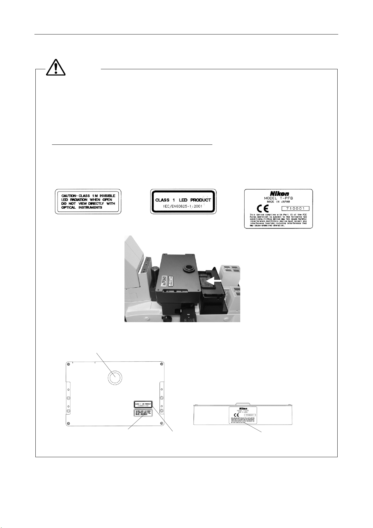
Location of the safety labels on the T-PFB Perfect Focus module
• The safety labels are affixed on the T-PFB Perfect Focus module.
• Under normal conditions, infrared rays are irradiated from the part in the figure below. Be careful.
(1) Caution label (2) Class 1 LED product label (3) Safety standard label
A
T-PFB Perfect Focus module
(For easy understanding, each
perture for the infrared ligh
emission
(1)
part is removed in this picture.)
(2)
View A
(3)
3
Page 6

Warning for Using this Product
2. Handle the system gently.
3. Do not disassemble.
4. AC adapter of the perfect focus (PF) controller
WARNING
Components of this system are precision optical instruments. Handle them carefully, and do not subject them
to any shocks.
In particular, the precision of the objectives can be adversely affected even by weak shocks.
Disassembly may cause malfunction and / or electric shock, and will lead to the forfeiture of all claims against
warranty. Do not disassemble any part other than those described in this manual. If you experience any
problem with this product, contact your nearest Nikon representative.
The PF controller uses the AC adapter as the power source. Be sure to use the adapter specified in Chapter
IX, “Specification.” Use of other adapter may cause a malfunction, abnormal heating, or serious damage.
• To avoid malfunction or the risk of fire, locate the AC adapter on the well-ventilated place. Do not cover the AC
adapter with any materials, otherwise poor heat radiation may cause overheating of it.
• Before connecting the AC adapter to the PF controller, be sure to turn off the power switch of the PF controller (flip
to the O side) to avoid malfunctions.
5. Power cord for the AC adapter of the PF controller
To prevent electric shock, always turn off the power switch (switch to the O side) of the PF controller before
attaching or detaching the power cord. Use one of the power cords specified in Chapter IX, “Specification.”
Use of an improper power cord can result in fire or other hazard. Also note that the power supply is classified
as subject to the protection class I against electric shock. Therefore, be sure to connect it to a protective earth
terminal.
4
Page 7

Warning for Using this Product
1. Do not take a look at the radiation light from the LED.
2. Do not wet the instrument.
3. Dirt on the lens
4. Installation location
CAUTION
When this instrument is turned on, weak near-infrared rays (infrared band) are emitted through the objective.
The light intensity is categorized as Class 1 level and is not harmful. But avoid direct viewing.
If the instrument gets wet, a short circuit may cause a malfunction or abnormal heating. If you accidentally spill
a liquid on the instrument, immediately turn off the power switch (flip to the O side) and unplug the power cord
from the wall outlet. Then use a dry cloth to wipe away the moisture. If any liquid gets inside the instrument,
do not use it; instead, contact your nearest Nikon representative.
Scratches, dirt, and fingerprints on the optical parts, such as lenses and filters, will adversely affect the
microscope image. If these parts get dirty, clean them by following the instructions described in Chapter VIII,
“Care and maintenance.”
Using or storing this instrument under unsuitable conditions may damage it or may have an adverse effect on
its accuracy. The following conditions should be kept in mind when selecting the installation location:
• Choose a flat surface with little vibration.
• Choose a location less exposed to hazards in the event of collisions, earthquakes, or other potential disasters. If
required to keep the device from falling, use strong wires or other means to secure this product to the worktable or
to another heavy, stable item.
• Avoid a brightly lit location such as a room that receives direct sunlight.
• Choose a location that is free from dust or dirt.
• Do not install this product in a hot and humid location. (Mold or condensation will form on the lenses and filters.)
• The room light just above the microscope may come into the objective as an extraneous light. (Especially when
using a condenser lens with longer working distance such as SLWD, ELWD and LWD lenses.) To avoid this, Nikon
recommends turning off the room light above the microscope when observing the image.
• Install the equipment in a location where the power cord can be easily unplugged from the AC inlet of the AC
adapter in case of emergency.
5. Focusing knobs
• Never turn the focus knobs on the left and right sides of the microscope in opposite directions at the same time, as
doing so can result in damage to the microscope.
• Turning the coarse focus knob as far as it will go and then attempting to turn it further will result in damage to the
microscope. Never use undue force to turn the knob.
• The coarse focus knob turns in sync with the motorized escape, refocus movements, or calling of the nosepiece
up/down position. To prevent malfunctions, avoid contact with the coarse focus knob during the knob is rotating.
6. Vibrations during motorized operation
This product is designed to minimize vibrations caused by motors inside, however, note that even the
minimized vibration may affect on image observation depending on service condition.
7. Electromagnetic waves
This product emits weak electromagnetic waves. The accuracy of any precision electronic equipment may be
adversely affected if positioned too close. If this product affects TV or radio reception, move the radio or TV
further away from the product.
5
Page 8

Contents
Preface................................................................................................................................................................................ 1
Warning for Using this Product ........................................................................................................................................... 2
I Overview ...................................................................................................................................................................... 8
1 Overview.............................................................................................................................................................. 8
2 Features............................................................................................................................................................... 8
3 Offset function ........................................................................................................................................................ 8
4 Specimen ............................................................................................................................................................... 9
4.1 Suitable specimen ........................................................................................................................................... 9
4.2 Suitable objectives........................................................................................................................................... 9
4.3 Not-suitable specimen................................................................................................................................... 10
II Name and Function of Each Part ............................................................................................................................... 11
1 Name of Each Part .......................................................................................................................................... 11
2 T-PFC PF Controller............................................................................................................................................. 12
III Preparation................................................................................................................................................................. 14
1 T-RCP Remote Control Pad................................................................................................................................. 14
2 Startup and Shutdown of the Remote Control Pad............................................................................................... 16
3 Registering Data of the Objectives ....................................................................................................................... 17
For deleting the registered data........................................................................................................................... 19
Important: list of objectives requiring data registration......................................................................................... 19
4 Registering Installation Information of Objectives Mounted on Nosepiece........................................................... 19
IV Operating Procedures ................................................................................................................................................ 21
1 Basic Operation.................................................................................................................................................... 21
2 Registering and Restoring the Offset Amount ...................................................................................................... 23
2.1 Registering the Offset Amount....................................................................................................................... 23
2.2 Restoring the Offset Amount ......................................................................................................................... 24
3 Registering and Restoring the Vertical Position of the Nosepiece........................................................................ 24
3.1 Registering the Vertical Position of the Nosepiece........................................................................................ 24
3.2 Escaping the Objective.................................................................................................................................. 25
3.3 Restoring the Vertical Position of the Nosepiece........................................................................................... 25
3.4 About the Movement of the Objective in Registering and Restoring the Vertical Position of the Nosepiece. 26
V Connecting a PC........................................................................................................................................................ 27
Connecting a PC ................................................................................................................................................. 27
Communications cable........................................................................................................................................ 27
Specification for serial interface communication.................................................................................................. 27
Communication commands................................................................................................................................. 27
VI Assembling................................................................................................................................................................. 28
Required tools ..................................................................................................................................................... 28
Block diagram...................................................................................................................................................... 29
1 Checking Components ......................................................................................................................................... 30
2 Mounting the T-FLC2-E Motorized Cassette Holder............................................................................................. 30
3 Mounting the T-PFB PF Module........................................................................................................................... 31
6
Page 9

Contents
4 Mounting Stage-up Kits ........................................................................................................................................ 31
5 Mounting the Motorized Nosepiece ...................................................................................................................... 31
6 Mounting the Stage .............................................................................................................................................. 32
7 Mounting IR-cut Filters ......................................................................................................................................... 32
8 Connecting Cables ............................................................................................................................................... 33
Rear view of the PF Controller ............................................................................................................................ 33
Cables ................................................................................................................................................................. 33
Checking Connections......................................................................................................................................... 34
VII Troubleshooting ......................................................................................................................................................... 35
1 During System Startup ......................................................................................................................................... 35
2 While Using the Perfect Focus Functions............................................................................................................. 35
VIII Care and Maintenance............................................................................................................................................... 38
1 Lens Cleaning ...................................................................................................................................................... 38
2 Cleaning This Product ...................................................................................................................................... 38
3 Disinfecting This Product ................................................................................................................................. 38
4 Storage ............................................................................................................................................................... 38
5 Periodical Inspections (Expenses Charged) ................................................................................................. 38
IX Specifications ............................................................................................................................................................. 39
7
Page 10

I
Overview
This chapter explains the overview of the perfect focus system.
1 Overview
Nikon perfect focus system is provided for Nikon inverted microscope ECLIPSE TE2000-E to track the focus
automatically.
This system detects the boundary surface between the cover glass* and aqueous solution of the specimen. When a dry
type objective is used, this system detects the boundary surface between the cover glass and air. And the detection is
performed by using a near infrared light (infrared band), which does not interfere with general observations, and controls
the focus of the microscope by tracking the vertical fluctuation of the boundary surface. That is, this system is free from
the specimen’s state change and color fading during fluorescent observation and keeps the focus at a steady position by
automatically correcting the minute defocus caused by changes over time, stage movement, and so on. This system is,
therefore, suitable for continuous observations and capturing images with a camera for changes of a living organic cell
and so on.
*: The cover glass is the bottom part of the glass bottom dish.
2 Features
• As the infrared band light is used for the focusing control, which is insensitive to a specimen and does not interfere
with the fluorescent microscopy, the focus-keeping and the fluorescent microscopy can be done simultaneously.
• The focus position can be adjusted manually with the optical offset function.
• The vertical position (position on the Z-axis) of the nosepiece and the focus offset amount for each objective can be
registered.
• The focus can be kept on the image-capturing specimen located at any place in the view field.
• Automatic adjustment of the defocusing can be done for any type of observation cameras and methods including
observation by naked eyes, that is, without restriction by the camera type, not alike the image contrast method.
3 Offset function
This system detects the boundary surface between the cover glass and aqueous solution of the specimen using a near
infrared light (infrared band) and controls focusing using the boundary surface as the reference position.
The objective of the microscope tracks the up/down changes of the boundary surface caused by the defocusing over
time and the stage movement when controlling the focus.
To focus on a desired point on the specimen, adjust the OFFSET knob on the perfect focus controller.
The offset amount is defined as the deviation of the focus point from the reference position (boundary surface) to where
the focus point is moved by adjusting the OFFSET knob. Keeping the specified offset amount, focusing can be controlled
so as to track the up/down changes of the boundary surface. The range of the offset amount depends on the objective. In
particular, when a water or oil immersion type objective is used, the offset amount is limited in the downward.
8
Page 11
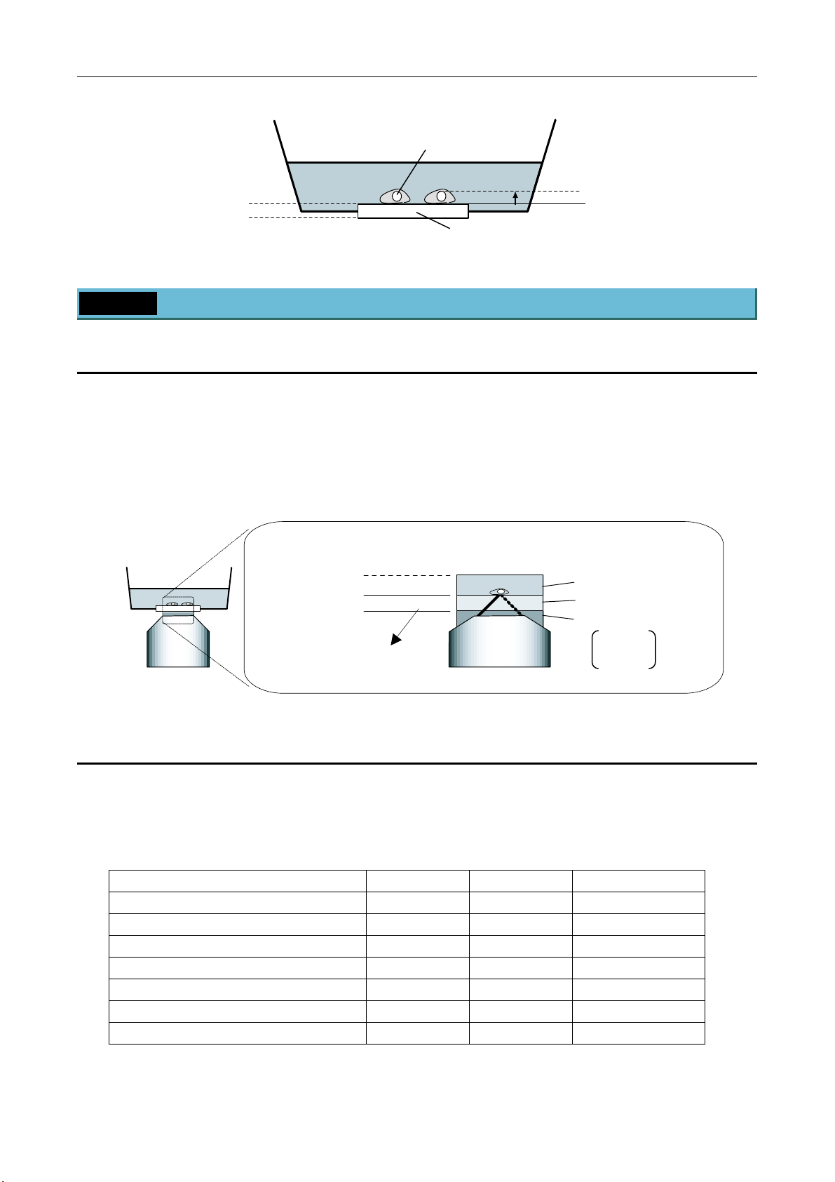
I Overview
Specimen
Detected boundary surface
(water or oil immersion)
Detected boundary surface
(dry type)
Aqueous solution
Cover glass
4 Specimen
4.1 Suitable specimen
Cells touching the upper surface of the cover glass of the glass bottom dish
Cover glass thickness: 150 to 180 µm (No.1S)
refractive index: 1.5
Aqueous solution (culture solution) depth: 3 mm or more
refractive index: 1.33 or near
Boundary surface
(water or oil immersion)
Boundary surface
(dry type)
t = 165±15 µm
(Standard: No.1S)
≥ 3 mm
t
Offset amount
Refractive index
Culture solution: up to 1.35
Cover glass: up to 1.5
Water: 1.33
Oil: 1.514
Air: 1.0
4.2 Suitable objectives
The following objectives are suitable for this system. If another objective is attempted to be used, an error will occur and
the LED of the [Obj Err] on the perfect focus controller will be lit.
If the LED of the [Obj Err] is lit, refer to the VII. Troubleshooting.
Name NA WD (mm) Type
Plan Fluor 40x 0.75 0.72 dry
Plan Fluor 40xH 1.30 0.2 oil immersion
Plan Fluor ELWD 20xC 0.45 7.6 dry
Plan Fluor ELWD 40xC 0.6 2.9 dry
Plan Fluor ELWD DM 20xC 0.45 7.6 dry
Plan Fluor ELWD ADL 20xC 0.45 7.6 dry
Plan Fluor ELWD ADL 40xC 0.6 2.9 dry
9
Page 12

I Overview
Name NA WD (mm) Type
Plan Apo VC 60xH 1.40 0.13 oil immersion
Plan Apo VC 100xH 1.40 0.13 oil immersion
Plan Apo VC 60xWI 1.20 0.27 water immersion
Plan Apo 60xHA 1.40 0.21 oil immersion
Plan Apo 100xH 1.40 0.13 oil immersion
Plan Apo 60xWI 1.20 0.22 water immersion
Plan Apo 20x 0.75 1.00 dry
Plan Apo DM 60xH 1.40 0.21 oil immersion
Plan Apo DM 100xH 1.40 0.13 oil immersion
Plan Apo TIRF 60x 1.45 0.13 oil immersion
4.3 Not-suitable specimen
The following specimens are hard to be observed. Because the focus control cannot be performed by reason of that the
reflection signal of the infrared is weak or the scattered light is strong.
(1) Fixed specimen
Usually a fixed specimen is filled with mounting medium. And this medium has a high refractive index. So, the
difference of the refractive indexes between the cover glass and the specimen is relatively small. Therefore,
enough reflection for the detection cannot be get.
(2) Sliced specimen
A sliced specimen is thick and its scattered light is strong. So, the reflection is hard to detect because the reflection
from the boundary surface is relatively weak.
(3) Specimen of strong reflection or strong light scattering
In addition to the sliced specimen, if a specimen has a strong light scattering, the weak reflection from the boundary
surface is hard to detect as is the case of (2).
(4) Cells touching the bottom glass with the thickness of 170 µm or more
When a dry type objective is used for a specimen with a thick bottom glass, the offset amount may be insufficient to
observe the boundary surface. So, the focusing range cannot be secured. (For an oil immersion type objective, the
boundary surface may be detected. But this method is not recommend. Use the cover glass of No.1S.)
(5) Specimen mounted on a plastic dish
A plastic dish is not recommended because the boundary surface is not suitable for the detection.
(6) Specimen mounted on a dirty cover glass
This system detects the surface of the cover glass and controls focusing. So, if the surface of the cover glass is not
clean, it will adversely affect the detection. Please clean the cover glass beforehand.
10
Page 13
II
Name and Function of Each Part
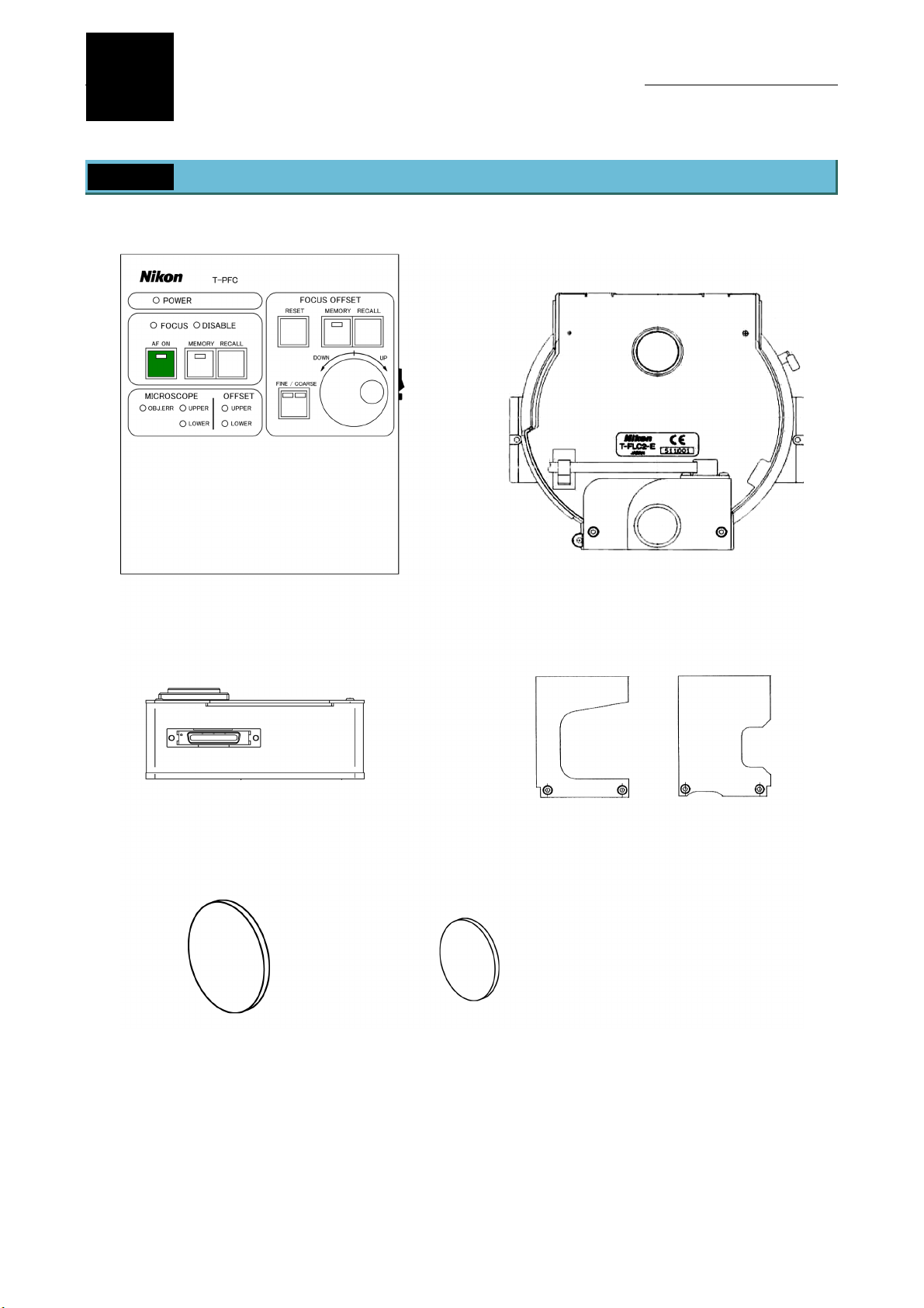
1 Name of Each Part
T-PFC perfect focus controller
T-PFB perfect focus module
T-FLC2-E motorized cassette holder
T-PFB perfect focus module pillars
IR-CUT filter of 45 mm diameter IR-CUT filter of 25 mm diameter
11
Page 14

II Name and Function of Each Part
2 T-PFC PF Controller
T-PFC PF controller
(1) [POWER] LED
(2) [FOCUS] LED
(3) [DISABLE] LED
(4) [AF ON] key/LED
(5) [AF - MEMORY]
key/LED
(6) [AF - RECALL] key
(7) [MICROSCOPE -
OBJ.ERR] LED
(8) [MICROSCOPE -
UPPER] LED
(9) [MICROSCOPE -
LOWER] LED
(12) [FOCUS OFFSET -
RESET] key
(13) [FOCUS OFFSET -
MEMORY] key/LED
(14) [FOCUS OFFSET -
RECALL] key
(15) [FINE/COARSE]
key/LED
(16) [OFFSET] knob
(10) [OFFSET_UPPER]
LED
(11) [OFFSET - LOWER]
LED
(1) [POWER] LED
This LED indicates the power on or off state, and is lit when the power is on.
(2) [FOCUS] LED
This LED is lit when the boundary surface comes into focus when controlling the focus (or when the [AF ON]
LED is lit). And, this LED blinks when the boundary surface comes into the focus control range.
(3) [DISABLE] LED
This LED blinks when the boundary surface is out of the focus control range (or when the [AF ON] LED is lit). Or,
this LED blinks when the nosepiece vertical position (the Z-axis position) is being restored.
(4) [AF ON] key/LED
This key switches the focus control status. The LED is lit when the focus control is on.
(5) [AF - MEMORY] key/LED
This key registers the nosepiece vertical position (the Z-axis position). The LED is lit when the vertical position
is registered.
(17) [LED] switch (18) [POWER] switch
12
Page 15

(6) [AF - RECALL] key
This key restores the registered nosepiece vertical position (the Z-axis position), and starts the focus control.
(7) [MICROSCOPE - OBJ.ERR] LED
This LED is lit when an error occurs. (Refer to VII. Troubleshooting.)
(8) [MICROSCOPE - UPPER] LED
This LED is lit when the objective reaches the upper limit of its movable range.
(9) [MICROSCOPE - LOWER] LED
This LED is lit when the objective reaches the lower limit of its movable range.
(10) [OFFSET_UPPER] LED
This LED is lit when the offset amount reaches the upper limit of the adjustable range.
(11) [OFFSET - LOWER] LED
This LED is lit when the offset amount reaches the lower limit of the adjustable range.
(12) [FOCUS OFFSET - RESET] key
This key moves the vertical position to where the offset amount is zero.
(The position may be shifted from the boundary surface because of variations of cover glass thickness or
microscopy conditions.)
II Name and Function of Each Part
(13) [FOCUS OFFSET - MEMORY] key/LED
This key registers the offset amount. The LED is lit when the offset amount is registered.
(14) [FOCUS OFFSET - RECALL] key
This key calls the registered offset amount.
(15) [FINE/COARSE] key/LED
This key switches the [OFFSET] knob between the fine adjustment and the coarse adjustment. The left LED is
lit when the fine adjustment and the right LED is lit when the coarse adjustment.
(16) [OFFSET] knob
To adjust the offset amount, rotate this knob.
(17) [LED] switch
This switch turns on/off all LEDs on the controller.
(18) [POWER] switch
This switch turns on/off the power.
Electronic sound at operation
While performing the PF controller, pressing any of the usable keys issues a short electronic sound to notify an
operator that the specified operation is started. Pressing a key disabled by the device issues no sound and
executes nothing.
13
Page 16

III
Before using this system, information of objectives must be registered into the T-RCP remote control pad. This chapter
explains the procedure to register the information of objectives into the remote control pad.
Preparation
1 T-RCP Remote Control Pad
8
1
2
3
4
5
6
9
10
11
12
13
14
15
16
17
18
7
14
Page 17

III Preparation
No. Name Functions available when the operation window is displayed
Functions available when the setting menu
or maintenance menu is displayed
1 LCD
2 [OBJECTIVE] keys These keys switch the objectives.
3 [Shutter A] key This key opens/closes the shutter allocated to the shutter A.
4 [Shutter B] key This key opens/closes the shutter allocated to the shutter B.
5 [EXCITER] keys These keys switch the excitation filters.
6 [BARRIER] keys These keys switch the barrier filters.
7 [EPI-FILTER] keys These keys switch the filter blocks.
8 [Z-AXI.RESET] key This key resets the indication of the Z-axis position to “0.”
[CAMERA EXP.]
9
key
10 [LCD MODE] key This key switches the LCD display mode. This key switches the LCD display mode.
11 [LCD ON/OFF] key This key turns on/off the backlight of the LCD.
[LCD Bright/Dark]
12
keys
[DIA LAMP
13
REMOTE] key
[DIA LAMP
14
ON/OFF] key
The operation window displays the positions of motorized
parts and the information on the installed optical parts.
This key produces an external trigger output.
These keys adjust the brightness of the backlight of the LCD.
This key switches on/off the remote control for the
dia-illumination lamp.
This key turns on/off the dia-illumination lamp.
The setting menu displays the settings of
motorized parts.
These keys are used to enter alphanumeric
characters.
[DIA LAMP ADJ.]
15
keys
[CONDENSER]
16
keys
[ANALYZER
17
IN/OUT] key
18 [LIGHT PATH] keys These keys switch the optical path.
These keys adjust the lamp voltage for the dia-illumination.
These keys switch the condenser cassettes.
This key moves in/out the analyzer.
PREV and NEXT keys (These keys changes
the selection.)
BS key (This key deletes the entered
character.), CLR key (This key clears all
characters.)
Cursor keys (These keys select item.),
Return key (This key accepts the selection.)
15
Page 18

III Preparation
A
2 Startup and Shutdown of the Remote Control Pad
Startup
1
1) Turn on the power supply for the dia-illumination lamp.
When you use the Uniblitz shutter, be sure to power on
the Uniblitz shutter controller.
2) Power on the hub controller.
3) The hub controller supplies the power to the remote
control pad.
The [Title] window appears on the LCD of the remote control pad, then, the [Operation] window appears in a
few seconds.
T-RCP REMOTE CON TROL PAD
V2.10
Connect the designated
C adapter.
[HUB controller side view]
Power
switch
[Title] window [Operation] window
Note
When the remote control pad is used at the first time, the [Operation] window is displayed as shown below
because the default settings of the installation information for the objectives and so on are “not installed.”
“---“ denotes “not installed.”
Besides, if a motorized device is not connected to the hub controller, the display for it is left blank. If the
device is connected in a wrong way, the hub controller cannot recognize the device and the display for the
device is also left blank.
If all motorized devices are not connected, the subject field is displayed as shown below.
Shutdown
2
1) Power off the hub controller.
2) Power off the dia-illumination lamp and Uniblitz shutter
controller.
16
Page 19

III Preparation
3 Registering Data of the Objectives
Before shipping, most data of objectives available in this system have been registered into the remote control pad. To
use objectives not registered in the pad, such objectives as newly put in the market, data for the objectives concerned
must be newly registered into the remote control pad.
• Up to nine data of objectives can be registered.
• A wrong data registration disables this system for safety consideration.
• For the list of objectives those need registrations, see “List of objectives requiring registration,” in this section.
Press the [MODE] key. The [SETTING] menu appears.
1
Select “Objective” by manipulating the [S] or [T] key, then
press the [ ] key.
Objective
Condenser
Filter
Exciter
Barrier
Combination(O bj.>Condense r)
Combination(F ilter>EX/BA)
More
SETTING MENU
Select “Edit” by manipulating the [S] or [T] key, then press the
2
[ ] key.
By manipulating the [PREV] and [NEXT] keys, select one of
3
“Other 1” to “Other 9” in the “Location” field to register the
desired objective.
Move the cursor to “Series” by manipulating the [S] or [T] key.
4
Select the series name of the objective by using the [PREV] and
[NEXT] keys.
OBJECTIVE
Series Mag. Esc.
1[P Fluor ][DL 4x][-]
2[P Fluor ][DL 10x][-]
3[P Fluor ][ELW D DM 20x ][*]
4[P Fluor ][ELW D DM 40x ][*]
5[P Fluor ][ELW D DLL 60x][ *]
6[P Fluor ][DLL 100x][*]
Edit
EDIT OBJECTIV E DATA
Location:[
Series :[――――― ―――――]
Mag. :[0 ]x
N.A. :[0 ]
W.D. :[0 ]
Type :[――――― ―――――]
EDIT OBJECTIV E DATA
Location:[Other 1]
Series :[
Mag. :[1 ]x
N.A. :[0。001 ]
W.D. :[0。01 ]
Type :[dry ]
Other1]
Other ]
17
Page 20

III Preparation
Move the cursor to “Mag.” by manipulating the [S] or [T] key.
5
Select the magnification of the objective by using the [PREV]
and [NEXT] keys.
Note that the cursor may not move to “Mag.”, if any data is not
entered in the field of “Series” (shown as [-----]).
Move the cursor to “N.A.” by manipulating the [S] or [T] key.
6
By manipulating the numerical key, [W] key, and [X] key, enter
the numerical aperture.
Note that available values are from 0.001 to 2.000. If an entered
value exceeds the lower or upper limit, that value is
automatically set to the appropriate limit.
Move the cursor to “W.D.” by manipulating the [S] or [T] key.
7
By manipulating the numerical key, [W] key, and [X] key, enter
the working distance.
Note that available values are from 0.01 to 40.00. If an entered
value exceeds the lower or upper limit, that value is
automatically set to the appropriate limit.
EDIT OBJECTIV E DATA
Location:[Other 1]
Series :[Other ]
Mag. :[
N.A. :[0。001 ]
W.D. :[0。01 ]
Type :[dry ]
EDIT OBJECTIV E DATA
Location:[Other 1]
Series :[Other ]
Mag. :[10 ]x
N.A. :[
W.D. :[0。01 ]
Type :[dry ]
EDIT OBJECTIV E DATA
Location:[Other 1]
Series :[Other ]
Mag. :[10 ]x
N.A. :[0.25 ]
W.D. :[
Type :[dry ]
10 ]x
0.25 ]
6.2 ]
Move the cursor to “Type” by manipulating the [S] or [T] key.
8
Select the type of the objective by using the [PREV] and [NEXT]
keys.
To continue the registration, move the cursor to “Location” by
9
manipulating the [S] or [T] key.
Then repeat steps from 3 to 8.
When settings are completed, press the [MODE] key. The
10
[Operation] window reappears.
EDIT OBJECTIV E DATA
Location:[Other 1]
Series :[Other ]
Mag. :[10 ]x
N.A. :[0.25 ]
W.D. :[6.2 ]
Type :[
EDIT OBJECTIV E DATA
Location:[
Series :[――――― ―――――]
Mag. :[0 ]x
N.A. :[0 ]
W.D. :[0 ]
Type :[――――― ―――――]
dry ]
Other2]
18
Page 21

III Preparation
For deleting the registered data
(1) Manipulating the [▲] or [▼] key, move the cursor to “Location”. Then select the data to be deleted by using the
[PREV] and [NEXT] keys.
(2) Press the [CLR] key.
Important: list of objectives requiring data registration
To use the objectives below, data should be registered beforehand.
Name of objective
Value to be registered
Series Mag N.A. W.D. Type
Plan Apochromat VC60xH PlanApo 60 1.40 0.13 oil
Plan Apochromat VC100xH PlanApo 100 1.40 0.13 oil
Plan Apochromat VC60xWI PlanApo 60 1.20 0.27 WI/C
Plan Apochromat TIRF60xH PlanApo 60 1.45 0.13 oil
4 Registering Installation Information of Objectives Mounted
on Nosepiece
Register the installation information of the objectives mounted on the nosepiece.
• Register the installation information of each objective mounted on one of the six addresses on the nosepiece.
• If the corresponding objective has not been registered, its data must be registered. For the detailed information, see
Section 3, “Registering Data of Objectives” in this chapter.
Press the [MODE] key, then, the [SETTING MENU] window
1
appears.
Select “Objective” by manipulating the [S] or [T] key, then
press the [ ] key.
Objective
Condenser
Filter
Exciter
Barrier
Combination(O bj.>Condense r)
Combination(F ilter>EX/BA)
More
SETTING MENU
Select the “Series” type for the objective by manipulating the
2
[PREV] and [NEXT] keys. The number at the left denotes the
address on the nosepiece.
19
OBJECTIVE
Series Mag. Esc.
1[
P Flu or ][― ―――― ―――――― ――――][-
2[――――――――――][――――――― ―――――― ――][-
3[――――――――――][――――――― ―――――― ――][-
4[――――――――――][――――――― ―――――― ――][-
5[――――――――――][――――――― ―――――― ――][-]
6[――――――――――][――――――― ―――――― ――][-
Edit
Type N.A. W.D.
Dry 0.13 17.10
]
]
]
]
]
Page 22

III Preparation
Move the cursor by manipulating the [W] or [X] key.
3
Select the “Mag.” (magnification) for the objective, by using the
[PREV] and [NEXT] keys.
Move the cursor by manipulating the [W] or [X] key.
4
Specify the “Esc.” setting for the objective, by using the [PREV]
or [NEXT] key.
*: When changing the objective, the subject objective
automatically goes down to the escape position and
restores after the change is completed.
-: The objective is changed without escaping.
Note
When the “*” set objective exists between “-“ set
objectives, changing “-“ set objectives each other causes
automatic escape.
Change the objective address by using the [S] or [T] key and
5
repeat steps from 2 to 3.
OBJECTI VE
Series Mag. Esc.
1[P Flu or ][
2[――――― ―――――][―――――――――――――――][ -]
3[――――― ―――――][―――――――――――――――][ -]
4[――――― ―――――][―――――――――――――――][-
5[――――― ―――――][―――――――――――――――][ -]
6[――――― ―――――][―――――――――――――――][-
Edit
Type N.A. W.D.
Dry 0.13 17.10
OBJECTI VE
Series Mag. Esc.
1[P Flu or ][DL 4x][
2[――――― ―――――][―――――――――――――――][ -]
3[――――― ―――――][―――――――――――――――][ -]
4[――――― ―――――][―――――――――――――――][-
5[――――― ―――――][―――――――――――――――][ -]
6[――――― ―――――][―――――――――――――――][-
Edit
Type N.A. W.D.
Dry 0.13 17.10
OBJECTI VE
Series Mag. Esc.
1[P Flu or ][DL 4x][ ―]
2[
―――――― ――――][―――――――――――――――][-]
3[――――― ―――――][―――――――――――――――][ -]
4[――――― ―――――][―――――――――――――――][-
5[――――― ―――――][―――――――――――――――][ -]
6[――――― ―――――][―――――――――――――――][-
Edit
Type N.A. W.D.
―――――― ―――― ― ―――― ― ――――
DL 4x][-]
]
]
-]
]
]
]
]
When settings are completed, press the [MODE] key. The
6
[Operation] window reappears.
20
Page 23

V
I
This chapter explains the basic operation to observe specimens with the perfect focus system by following the actual
observation procedures.
• If the system has not been assembled, see Chapter VI, “ Assembling.”
• For operating procedures of each part of the microscope, see the instruction manual attached to the microscope.
(Inverted Microscope ECLIPSE TE2000-E Instructions)
• Before using this system, read warnings and cautions described in “Warning and Caution for Using this Product”
carefully and thoroughly, and be sure to follow them.
• For the devices using with this system (epi-fl attachment, differential interference contrast attachment, various
motorized devices, and so on), read warnings and cautions described in the instruction manuals of these devices
carefully and thoroughly, and be sure to follow them.
Operating Procedures
1 Basic Operation
Power on the microscope.
1
Caution: When the PF controller is turned on, the PF module will be initialized for about 10 seconds
and the information about the objectives on the nosepiece are acquired from the HUB
controller. So, before the PF controller, the microscope must be turned on.
Besides, if the information of the objectives is changed, the PF controller must be turned off
once, and then, turned on again.
Using the T-RCP remote control pad, register the information of the objectives mounted on the microscope into
2
the hub controller.
For detailed information about the registration procedure, see Chapter III, “Before Using this System.”
Turn on the power switch (switch to “I”) located on the right side face of the PF controller to power on the
3
controller.
The [POWER] LED, located on the front face of the PF controller, is lit.
Select the desired objective and put the specimen on the stage.
4
• Put the objective supported by this system into the optical path. Refer to IX. Specifications.
• The objective can be selected by using the remote control pad. For more information, see the instruction
manual of the remote control pad.
• Apply water immersion or oil immersion, if required. For more information, see, the instruction manual of the
microscope.
Focus on the specimen by using the coarse/fine focus knob on the microscope.
5
21
Page 24

IV Operating Procedures
Press the [AF ON] key on the PF controller.
6
(1) The LED of the [AF ON] key is lit and the focus control
starts.
Caution: Manual operation of the fine focus knob is
disabled during the focus control. Do not
touch the coarse focus knob, however,
because this knob is not disabled during the
focus control.
(2) When the objective comes into the focus control range,
the [FOCUS] LED blinks. When the reference position
(boundary surface) comes into focus, the [FOCUS] LED is
lit.
* The focus control range is defined that the focus control
can be performed, and is predetermined for each
objective.
For blinking of the [DISABLE] LED:
The reference position (boundary surface) is not in the focus
control range if the LED blinks. Adjust the objective position by
moving using the coarse/fine focus knob of the microscope so
that the reference position (boundary surface) comes into the
focus control range. When the reference position (boundary
surface) comes into the focus control range, the focus control
starts.
* The completion of focusing on the boundary surface does not mean that the target position of the
specimen comes into the focus. Perform the step 7 below, the [OFFSET] knob operation, for your
target. In particular, when a dry type objective is used, the initial position may be shifted from the
boundary surface because of variations of cover glass thickness. So, after the [FOCUS] LED is lit,
adjust the offset knob to focus on the target.
Time-out function:
This system has the time-out function to keep the objective from contact with specimen. This function will be
activated and the objective will be stopped if the signal cannot be detected within 5 seconds during the focusing
with the [AF ON] operation. (The objective moves about 400 µm for the 5 seconds.)
When the time-out function is activated, the buzzer beeps, the LED of the [AF-ON] turns off, and the up/down
movement of the objective stops.
Recovery from the time-out function:
The reference position (boundary surface) is out of the range. Push the [OFFSET-RESET] key to restore the
offset amount to its original status. Focus on the specimen manually. And then, push the [AF-ON] key again.
22
Page 25

IV Operating Procedures
Focus on the target of the specimen by manipulating the
7
[OFFSET] knob on the PF controller and start observation.
• Fine and coarse operations are provided for the function of
the [OFFSET] knob. The [FINE/COARSE] key can be used
to switch between the FINE operation and the COARSE
operation.
• The FINE/COARSE state can be checked with the LED on
the key.
Caution: The offset amount can be operated only when the
focus is being controlled (when the [AF ON] LED
is lit).
2 Registering and Restoring the Offset Amount
The offset amount specified during the observation can be registered into the memory of the PF controller. By pressing
the [FOCUS OFFSET – RECALL] key, the registered offset amount can be restored even after the offset amount is
changed by manipulating the [OFFSET] knob.
• The offset amount setting can be overwritten if required.
• Only one offset amount can be registered for one objective (one objective address). (Six positions are available in
total.)
• The registered offset amounts is stored while the PF controller is powered on.
2.1 Registering the Offset Amount
Adjust the offset amount by manipulating the [OFFSET] knob,
1
when the LED on the [AF ON] key of the PF controller is lit.
2
Press the [FOCUS OFFSET – MEMORY] key for over two
2
seconds.
The LED on the [MEMORY] key is lit and the offset amount is
registered.
1
23
Page 26

IV Operating Procedures
2.2 Restoring the Offset Amount
Press the [FOCUS OFFSET – RECALL] key.
1
The nosepiece automatically moves to the position for where
the offset is registered.
Caution: Manual operation of the fine focus knob is
disabled during the focus control. Do not touch
the coarse focus knob, however, because this
knob is not disabled during the focus control.
3 Registering and Restoring the Vertical Position of the
Nosepiece
The TE2000-E microscope has a linear encoder inside, and the vertical position (the Z-axis position) of the nosepiece
can be reproduced by using the coordinates of the linear encoder. With this function, the vertical position of the
nosepiece can be registered into the memory of the PF controller for the desired observation condition.
Once the position is registered, pressing the [AF – RECALL] key can return the nosepiece to the registered position or its
vicinity and then the system restarts the focus control even after the nosepiece position was changed by manipulating
the coarse and fine focus knobs. (Note: The nosepiece may not return to its registered absolute position of the vertical
movement. It will start the focus control again from the vicinity of the registered position.)
This function is useful for the case supplying oil to the objectives or replacing the specimen where the objectives must be
escape.
• The vertical position of the nosepiece can be overwritten if required.
• Only one offset amount can be registered for one objective (one objective address). (Six positions are available in
total.)
• The registered vertical position of the nosepiece is stored while the PF controller is powered on.
3.1 Registering the Vertical Position of the Nosepiece
Focus on the target of the specimen.
1
• When the [AF ON] LED is lit:
Focus on the target by rotating the [OFFSET] knob.
• When the [AF ON] LED is not lit:
Focus on the target by rotating the coarse/fine focus knob
on the microscope.
Press the [FOCUS OFFSET – MEMORY] key for over two
2
seconds.
The LED on the [MEMORY] key is lit and the vertical position
of the nosepiece is registered.
24
Page 27

IV Operating Procedures
3.2 Escaping the Objective
Press the [AF ON] key on the PF controller
1
(when the [AF ON] LED is lit).
The LED of the [AF ON] key is turned off and the focus control
is canceled.
Caution; The focusing control must be canceled before
changing or replacing the objectives.
Lower the nosepiece by manipulating the coarse focus knob, then, perform the required operation.
2
Examples of the operation:
• Replacing specimens
• Changing objectives
• Supplying oil or deionized water (or distilled water) to the objective
• The coarse focus knob is manipulated for other reasons, but the specimen is not moved.
3.3 Restoring the Vertical Position of the Nosepiece
The status must be one of the following two conditions.
1
[AF - MEMORY] LED: ON
[AF – ON] LED: OFF
Press the [AF – RECALL] key of the PF controller.
AF = OFF
or
[AF - MEMORY] LED: ON
[AF - ON] LED: ON
[DISABLE] LED: Blink
And no signal was detected although
the [AF - ON] key was pressed.
2
The buzzer sounds (one short beep). And then, the nosepiece
starts moving with blinking the [DISABLE] LED.
Caution: Manual operation of the fine focus knob is
disabled while restoring the nosepiece vertical
position. Do not touch the coarse focus knob,
however, because this knob is not disabled while
restoring.
Action of the equipment: When the nosepiece returned to the
3
registered vertical position or its vicinity, the [AF ON] LED is lit
and the focus control starts.
25
Page 28

IV Operating Procedures
If the buzzer sounds (twice short beep or one long beep),
the vertical position of the nosepiece could not be restored. Perform
the followings:
• Manipulate the [AF – MEMORY] operation at the focus position
again.
• Change the height of the stage by manipulating the coarse/fine
focus knob.
* The completion of focusing on the boundary surface does not mean that the target position of the specimen comes
into the focus. Perform the step 7, the [OFFSET] knob operation, in “Basic Operation ” for your target. In particular,
when a dry type objective is used, the initial position may be shifted from the boundary surface because of variations
of cover glass thickness. So, after the [FOCUS] LED is lit, adjust the offset knob to focus on the target.
3.4 About the Movement of the Objective in Registering and
Restoring the Vertical Position of the Nosepiece
(1) Push the [AF-MEMORY] key after focusing.
Glass bottom dish
(1)
(2)
WD/2
(4)
(5)
(6)
(7)
Beep!
The vertical position of the nosepiece is
stored. (The tip of the objective is defined as
“Z1” in this explanation.)
(2) Escape the objective to perform an operation
such as oil exchange or so on.
(3) Push the [AF-RECALL] key.
(4) The nosepiece is driven to the registered
vertical position, Z1, and additionally driven
upward at a distance of the half of the WD.
(The WD is the working distance of the
objective.)
However, if the half of the WD is greater than
750 µm, 750 µm is set in place of the
calculated value.
(5) The focus position (boundary surface) is
searched for downward.
(6) When the focus position is detected, the
searching operation ends and the AF is turned
on.
(7) If the focus position cannot be detected, the
search operation ends in 20 seconds and a
sound beeps.
Z1
26
Page 29

V
Connecting a PC
The hub controller can be controlled from the IBM PC-AT compatible computer connected to it.
Connecting a PC
Using a cross wired cable with D-SUB (9 pins) connectors, connect the “PC connector” of the hub controller and the
“serial port” of the PC.
Pin number of the PC
connector
1 DCD -
2 RxD Input
3 TxD Output
4 DTR Output
5 SG (GND)
6 DSR Input
7 RTS -
8 CTS -
9 RI -
Signal
Direction of the
signal
Communications cable
PC connector
PC connector: D-SUB (9pin) male
Pins numbered one, seven, eight, and nine
are opened inside the hub controller.
D-SUB (9 pins: female to female) and general cross wired cable (three meters maximum)
Specification for serial interface communication
Interactive signal connection circuit RS-232C (EIA standard compliant)
Baud rate 9600 bps
Data length 8 bit
Start bit 1
Stop bit 1
Parity check None
Communication commands
Contact your nearest Nikon representative.
27
Page 30

V
Assembling
I
This chapter explains how to assemble this system and how to connect required components.
• Before assembling, read warnings and cautions described in “Warning and Caution for Using this Product”
• To prevent electric shock and fire, always turn off the power switch (switch to “O”) of all devices and unplug the
• Do not let fingers or hands get caught in parts or components.
• Scratches or finger prints on the lens adversely affects the image quality. Pay close attention to assemble the
Warning
carefully and thoroughly, and be sure to follow them.
power cord from the wall outlet.
Caution
system and do not touch the lens.
• Components of this system are precision optical instruments. Handle them carefully, and do not subject them to
any shocks. The precision of the objectives in particular can be adversely affected even by a weak shock.
Required tools
Two 2-mm hexagonal screwdrivers (supplied with the microscope)
One 4-mm hexagonal wrench (supplied with the microscope)
One 2.5-mm hexagonal wrench (supplied with the motorized cassette holder)
28
Page 31

Block diagram
VI Assembling
T-PFB
perfect focus module *
Filter slider
Stage
Stage-up kit
T-PFC
perfect focus
controller *
Two pillars *
On the opposite side
T-FLC2-E
motorized cassette
holder *
Objective
Remote control
pad
AC
adapter
Motorized
nosepiece
Stage-up kit
Power cord
(for the AC adapter)
Stage-up kit
AC
adapter
Illumination pillar
Epi-fl attachment
Auxiliary filter
slider
Epi-illumination
lamp house
Power supply
Power cord
(for the power supply)
To the power
source for
the episcopic
illumination
External fine focus
knob (optional)
Either connection will do.
Power cord
(for the AC adapter)
”*” denotes the component of this system.
29
Page 32

VI Assembling
1 Checking Components
Check that the following components are prepared.
1. TE-2000E main body (including the hub controller and remote control pad)
2. TE-2000E stage-up kit
3. T-FLC2-E motorized cassette holder
4. T-PFB PF module (including two pillars)
5. T-PFC PF controller
6. Sensor cable
7. Control cable
8. Serial cable
9. AC adapter (for the PF controller)
10. IR-CUT filter (diameter 25 mm x 1 and 45 mm x 1)
2 Mounting the T-FLC2-E Motorized Cassette Holder
Insert the cassette holder into the attaching groove from over
1
the microscope.
Remove filter block cover. And fix the cassette holder with
2
screws on the left and right side by using the hexagonal
wrench.
Connect the cable of the cassette holder to the connector of the
3
FL block on the hub controller .
30
Page 33

VI Assembling
3 Mounting the T-PFB PF Module
Mount the two pillars for the PF module onto the motorized
1
cassette holder.
Viewing from the microscope’s front, mount the pillar with a
smaller cut on the right side of the holder facing the cut to the
rear.
On the left side of the holder, mount the pillar with a larger cut
facing to the front.
Fix each pillar using two hexagon socket headed bolts.
Mating the groove to the protrusions of each pillar, place the
2
module on the pillars.
Retain the PF module on the pillars using four hexagon socket
3
headed bolts.
4 Mounting Stage-up Kits
Mount three stage pillars.
1
Mating the positioning protrusions of the pillars to the grooves
of the microscope’s main body and retain each of them using
two hexagon socket headed bolts.
Fit the nosepiece pillar and retain it with two hexagon socket
2
headed bolts.
5 Mounting the Motorized Nosepiece
Mount the main body of the motorized nosepiece on the
1
nosepiece pillar attached in step 4, “Mounting Stage-up Kits.”
1
2
1
1
Retain the nosepiece with two M5-hexagon socket headed
2
bolts.
31
Page 34

VI Assembling
A
Connect the cable to the “Nosepiece connector” on the hub
3
controller.
Caution: Be sure to insert the objectives after mounting the stage
because they may be damaged if made contact.
6 Mounting the Stage
Place the stage on the stage pillars attached in step 4,
1
“Mounting Stage-up Kits.”
Retain the stage using four M5-hexagon socket headed bolts.
2
7 Mounting IR-cut Filters
This system uses the near infrared light (infrared band) derived from the infrared LED for the focus control. Since the
near infrared light (infrared band) used for the illumination system affects adversely on the focus control, therefore, place
the IR-cut filter on each optical path of the diascopic illumination and epi-fl illumination.
Caution: The Attached IR-cut filter reduces the intensity of ultraviolet rays too. Pay attention to observe with fluorescent
technique using the strong ultraviolet rays.
Attach the IR-cut filter (45 mm in diameter)
1
(1) Attach the filter to the filter slider.
(2) Insert the filter slider into the illumination pillar.
Attach the IR-cut filter (25 mm in diameter)
uxiliary filter slider
2
(1) Attach the filter to the auxiliary filter slider.
frame
IR-cut
filter
32
Page 35

VI Assembling
(2) Insert the filter slider into the epi-fl attachment.
8 Connecting Cables
Locate the PF controller on the stable place near the microscope, and then, connect the following cables. Be sure to
check that the hub controller and PF controller are both not powered when connecting cables.
Rear view of the PF Controller
(1) DCIN connector
Connects to the DC
power supply from the
AC adapter.
(2) CONTROL (EXP)
connector
Connects to the EXP
connector on the hub
controller with the control
cable.
Cables
1. Control cable
(3) SERIAL (STAGE) connector
Connects to the STAGE
connector on the hub
controller with the serial
communication cable,
(5) AUX. IN connector
Connects the cable of the
T-EFN external fine focus
knob (option). (This
connection is not required
if the T-EFN external fine
focus knob is not used.)
(4) SENSOR connector
Connects to the SENSOR connector
of the PF module with the sensor
cable.
Round type plug: to the EXP connector of the hub
controller
Rectangular type plug: to the control (EXP)
connector of the PF controller
Caution: Be sure to connect the round type plug to the EXP connector of the hub controller. Do not plug to
the AUX.IN connector of the PF controller.
33
Page 36

VI Assembling
2. Serial communication cable
3. Sensor cable
Rectangular type plug: to the STAGE connector of
the hub controller
Round type plug: to the SERIAL (STAGE)
connector of the PF controller
To the SENSOR connector of the PF controller
To the SENSOR connector of the PF module
Checking Connections
After connecting cables, power on the system and check to see each component.
Turn on the microscope.
1
Caution: When the PF controller is turned on, the PF module
will be initialized for about 10 seconds and the information
about the objectives on the nosepiece are acquired from the
HUB controller. So, before the PF controller, the microscope
must be turned on.
Besides, if the information of the objectives is changed, the PF
controller must be turned off once, and then, turned on again.
Turn on the [POWER] switch (switch to “I”) of the PF controller.
2
Check that the [POWER] LED is lit and the [OBJ.ERR] LED is
not lit.
34
Page 37

V
II
If the system does not function properly, take appropriate action as described below. If the problem is still not resolved
after referring to this section, please contact your nearest Nikon representative.
Troubleshooting
1 During System Startup
Problems Causes Countermeasures
The buzzer issues beeps
twice in a row.
Both the [OFFSET_UPPER]
LED and the
[OFFSET_LOWER] LED are
lit at the same time.
The
[MICROSCOPE-OBJ.ERR]
LED is blinking.
• The motorized nosepiece is not
mounted on the microscope.
• The objective is not in the click stop
position.
• The SENSOR connector of the PF
module and the SENSOR connector of
the PF controller are not connected
with the SENSOR cable.
• The EXP connector of the hub
controller and the CONTROL (EXP)
connector of the PF controller are not
connected with the CONTROL cable.
• Mount the motorized nosepiece on the
microscope.
• Rotate the objective into the click stop
position.
• Connect the SENSOR connector of the
PF module and the SENSOR
connector of the PF controller with the
SENSOR cable.
• Connect the EXP connector of the hub
controller and the CONTROL (EXP)
connector of the PF controller with the
CONTROL cable.
2 While Using the Perfect Focus Functions
Problems Causes Countermeasures
The [FOCUS] LED is lit at
times while the [AF ON] LED
is not lit.
-
It is normal. The [FOCUS] LED is lit when
the boundary surface is detected. Use it
as a guide of focusing.
The
[MICROSCOPE-OBJ.ERR]
LED is lit.
The
[MICROSCOPE-OBJ.ERR]
LED is lit. And the buzzer
issues beeps twice in a row.
The
[MICROSCOPE-UPPER]
LED is lit.
The
[MICROSCOPE-LOWER]
LED is lit.
• The hub controller has no usable
objective.
• No usable objective is selected.
• The cable connection is wrong.
The objective is not in the click stop
position.
The objective reaches the upper limit of
the vertical control.
The objective reaches the lower limit of
the vertical control.
• Register a usable objective into the hub
controller.
• Select a usable objective. For usable
objectives, see the list of objectives in
the Specification.
• Connect cables correctly referring to
the Chapter VI, “Assembling.”
Rotate the objective into the click stop
position.
Lower the specimen position (lower the
stage).
Raise the specimen position (raise the
stage).
35
Page 38

VII Troubleshooting
Problems Causes Countermeasures
The [OFFSET_UPPER] LED
is lit.
The [OFFSET_LOWER]
LED is lit.
Pressing the [FOCUS
OFFSET-MEMORY] key
causes nothing (no beep
from the buzzer).
Pressing the [AF-MEMORY]
key causes nothing (no beep
from the buzzer).
Pressing the [AF-RECALL]
key causes nothing (no
bleep from the buzzer).
Pressing the [AF-RECALL]
key causes beeps twice from
the buzzer and the
[AF-RECALL] does not work.
The [AF-RECALL] operation
ends after a long sound of
buzzer.
The offset amount reaches the upper limit
of the adjustable range.
The offset amount reaches the lower limit
of the adjustable range.
• The key was not pressed long enough.
• The [AF-RECALL] operation is in
progress.
• Press the key longer than two seconds.
• The [AF-MEMORY] operation has not
been done.
• No usable objective is selected (the
[MICROSCOPE-OBJ.ERR] LED is lit).
The objective is close to the upper or
lower limit of the vertical control.
• The focus position could not be
detected.
• The objective reached the upper or
lower limit of the vertical control while
focusing.
Lower the objective with the [OFFSET]
knob until the LED is turned off.
Raise the objective with the [OFFSET]
knob until the LED is turned off.
• Press the key longer than two seconds.
• The [FOCUS OFFSET-MEMORY] key
is disabled during the [AF-RECALL]
operation.
• The [AF-MEMORY] key is disabled
during the [AF-RECALL] operation.
• Perform the [AF-MEMORY] operation
in advance.
• Select a usable objective.
Change the stage position so that its
vertical position is apart from the upper or
lower limit.
• Perform the [AF-MEMORY] operation
at the focus position again.
• Change the stage position so that its
vertical position is apart from the upper
or lower limit.
• The nosepiece is rotated during the
[AF-RECALL] operation. (The system
operation is stopped for safety if the
nosepiece is rotated during the
[AF-RECALL] operation.)
• The focusing signal is distorted during
the [AF-RECALL] operation. If one of
the following actions is taken, the
focusing signal may be distorted and
the system stops its operation because
of safety:
* Abrupt vertical position change is
done by manipulating the coarse
focus knob of the microscope.
* The specimen is inclined.
* The specimen is removed.
36
Page 39

VII Troubleshooting
Problems Causes Countermeasures
Pressing the [AF ON] key
causes nothing (no bleep
from the buzzer).
The [DISABLE] LED is
blinking.
About 5 second after starting
the [AF ON] operation, the
buzzer beeps and the
focusing stops.
• No usable objective is selected (the
[MICROSCOPE-OBJ.ERR] LED is lit).
• No specimen is set.
• The objective is far from the boundary
surface of the specimen.
• The shape or material of the specimen
is not supported by this system.
• No specimen is set.
• The objective is far from the boundary
surface of the specimen.
• The shape or material of the specimen
is not supported by this system.
• Select a usable objective.
• Set a specimen and focus on it
manually.
• Adjust the objective closer to the
boundary surface of the glass by
manipulating the [OFFSET] knob.
• This perfect focus system may not
work precisely for specimens covered
by a thick glass plate or having a high
refractive index (n is nearly equal to
1.5). See p.7, 4.1 “Suitable specimen.”
• Set a specimen and focus on it
manually.
• Push the [OFFSET-RESET] key to
restore the offset amount to its original
status.
• This perfect focus system may not
work precisely if the specimen is
covered by a thick glass plate or the
aqueous solution has a high refractive
index (n is nearly equal to 1.5). See
p.7, 4.1 “Suitable specimen.”
37
Page 40

V
III
Care and Maintenance
1 Lens Cleaning
Do not let dust, fingerprints, and so on get on the lenses. Dirt on the lenses, filters, and so on will adversely affect the
view of the image. If any of the lenses get dirty, clean them as described below:
• Brush away dust with a soft brush, or wipe it away gently with gauze.
• Only if there are fingerprints or grease on a lens, dampen a piece of soft, clean cotton cloth, lens tissue, or gauze with
absolute alcohol (ethyl or methyl alcohol) and wipe.
• Only when removing the immersion oil off from the objective, use petroleum benzine. If you cannot obtain petroleum
benzine, use methyl alcohol. However, because methyl alcohol does not clean as well as petroleum benzine, it will be
necessary to wipe the surfaces repeatedly. (Usually, wiping three or four times is sufficient to clean the lenses.) Wipe
with absolute alcohol (ethyl or methyl alcohol) to finish.
• Never use petroleum benzine to clean the entrance lens at the bottom of the eyepiece tube and prism surface of the
eyepiece tube.
• Absolute alcohol and petroleum benzine are highly flammable. Be careful when handling it, when around open flames,
when turning the power switch on / off, and so on.
• When using absolute alcohol, be sure to follow the instructions provided by the manufacturer.
2 Cleaning This Product
• Nikon recommends that you use a silicon cloth to clean this product.
• For persistent dirt, dampen a piece of gauze with neutral detergent and wipe lightly.
• Note that using organic solvents could result in discoloration of the plastic parts.
3 Disinfecting This Product
• Nikon recommends that you use 70% medical alcohol for normal disinfection of this product.
• If a specimen is spilled, check that the specimen is a safe material or not. In case of spillage of a hazardous
specimen onto this product, follow your standard laboratory procedures.
• Note that using organic solvents could result in discoloration of the plastic parts.
4 Storage
Store this product in a dry place where mold is not likely to form.
Store the objectives and eyepieces in a desiccator or similar container with a drying agent.
Put a vinyl cover over this product to protect them from dust.
Before putting on the vinyl cover, turn off the power switch on the microscope (flip it to the “O” side) and wait until the
lamphouse is cooled down.
5 Periodical Inspections (Expenses Charged)
Nikon recommends inspecting this product periodically (expenses charged) in order to maintain peak performance.
Contact your nearest Nikon representative for details.
38
Page 41

IX
Microscope model TE2000-E
Target specimen Specimen in liquid (culture cell and so on)
Available container Glass bottom dish (glass thickness: No. 1S)
Glass thickness Standard No. 1S (150 to 180 µm)
Detection method Active type, infrared LED image projection method
Specifications
Detected
boundary
surface
Detector Inline CCD
Detector light source
Offset method Optical offset type: The offset value can be operated with the knob of the controller.
Offset amount
Focusing time 700 msec or less (near the boundary surface)
Focusing accuracy 1/3 of the depth of focus for each objective
Available microscopy
Available objective
Water or oil
immersion type
objective
Dry type objective Boundary surface between the glass and the air
Boundary surface between the glass and specimen (culture medium)
Refer to the figure on p.6 in Chapter I. “3. Offset function.”
Refer to the figure on p.6 in Chapter I. “3. Offset function.”
Infrared LED wavelength: 770 nm
illumination power: 0.1 mW or less
Dry type objective: +100 to –10 µm
Water immersion type objective: +50 to –2 µm
Oil immersion type objective: +10 to –0.5 µm
Note: Some objectives are available for greater offset amount than above.
Bright field microscopy, phase contrast microscopy, DIC microscopy, epi-fl
microscopy, TIRF microscopy
Name NA WD (mm) Type
Plan Fluor 40x 0.75 0.72 dry
Plan Fluor 40xH 1.30 0.2 oil immersion
Plan Fluor ELWD 20xC 0.45 7.6 dry
Plan Fluor ELWD 40xC 0.6 2.9 dry
Plan Fluor ELWD DM 20xC 0.45 7.6 dry
Plan Fluor ELWD ADL 20xC 0.45 7.6 dry
Plan Fluor ELWD ADL 40xC 0.6 2.9 dry
Plan Apo VC 60xH 1.40 0.13 oil immersion
Plan Apo VC 100xH 1.40 0.13 oil immersion
Plan Apo VC 60xWI 1.20 0.27 water immersion
Plan Apo 60xHA 1.40 0.21 oil immersion
Plan Apo 100xH 1.40 0.13 oil immersion
Plan Apo 60xWI 1.20 0.22 water immersion
Plan Apo 20x 0.75 1.00 dry
Plan Apo DM 60xH 1.40 0.21 oil immersion
Plan Apo DM 100xH 1.40 0.13 oil immersion
Plan Apo TIRF 60x 1.45 0.13 oil immersion
39
Page 42

IX Specifications
Memory function 1 Offset value registering/calling (for each objective, up to 6 values)
Memory function 2
Dimensions and weight T-PFB: H 46 x W 210 x D 125 mm (without protrusions) 1.5 Kg
Service condition
Designated AC adapter
Nosepiece up/down position registering/calling (for each objective, up to 6
positions)
T-PFC: H 65 x W 150 x D 202 mm (without protrusions) 2.2 Kg
T-FLC2-E: H 56 x W 166 x D 165 mm (partially H 117) 1.3 Kg
Operating environment
Temperature: +20 to +38 °C (for control unit: 0 to +40 °C).
Relative humidity: 60% or less (for control unit: 80% or less) * No condensation.
Altitude: 2000m max.
Pollution degree: Degree 2
Installation category: Category II
Electric shock protection class: Class I (AC adapter)
Indoor use only
Storage environment
Temperature: - 20 to +60 °C
Relative humidity: 90% or less. * No condensation.
Manufacturer: ILAN Electronics Ltd.
Type: F1650K
Input ratings: 100 to 240 VAC, max 1.2 A, 50-60 Hz.
Output ratings: 12 VDC, max 3.5 A
Others: UL listed product, GS approved, and CE satisfied.
Power cord
Safety standards compliance
For using in the area supplied voltage is 100 to 120 V:
UL listed detachable cord set, 3 conductor grounding Type SVT, AWG 18, 3 m
long maximum, rated at 125 V AC minimum.
For using in the area supplied voltage is 220 to 240 V:
Approved cord set according to EU/EN standards, 3 conductor grounding type
HO5VV-F, AWG 18, 3 m long maximum, rated at 250 V AC minimum.
LED product category:
Class 1 LED Product
CE marking
This product meets EU Low Voltage Directive requirements.
This product meets EU EMC Directive requirements. (EN61326)
This equipment has been tested and found to comply with the limits for a Class A
digital device, pursuant to Part 15 of the FCC Rules.
These limits are designed to provide reasonable protection against harmful
interference
when the equipment is operated in a commercial environment.
This equipment generates, uses, and can radiate radio frequency energy and, if
not
installed and used in accordance with the instruction manual, may cause harmful
interference to radio communications.
Operation of this equipment in a residential area is likely to cause harmful
interference
in which case the user will be required to correct the interference at his own
expense.
This Class A digital apparatus complies with Canadian ICES-003.
Cet appareil numérique de la classe A est conforme à la norme NMB-003 du
Canada.
This product meets Australian EMI. (AS/NZS CISPR11 Group 1 Class B)
40
 Loading...