

Page 1

PC-Nikkor
35mm
f/2.8
Nikon INSTRUCTION MANUAL
Page 2

Page 3

NOMENCLATURE
Preset ring alignment index
Preset ring
Aperture ring
Distance scale
Depth-of-field indicators
Infrared index
Distance scale index
Page 4
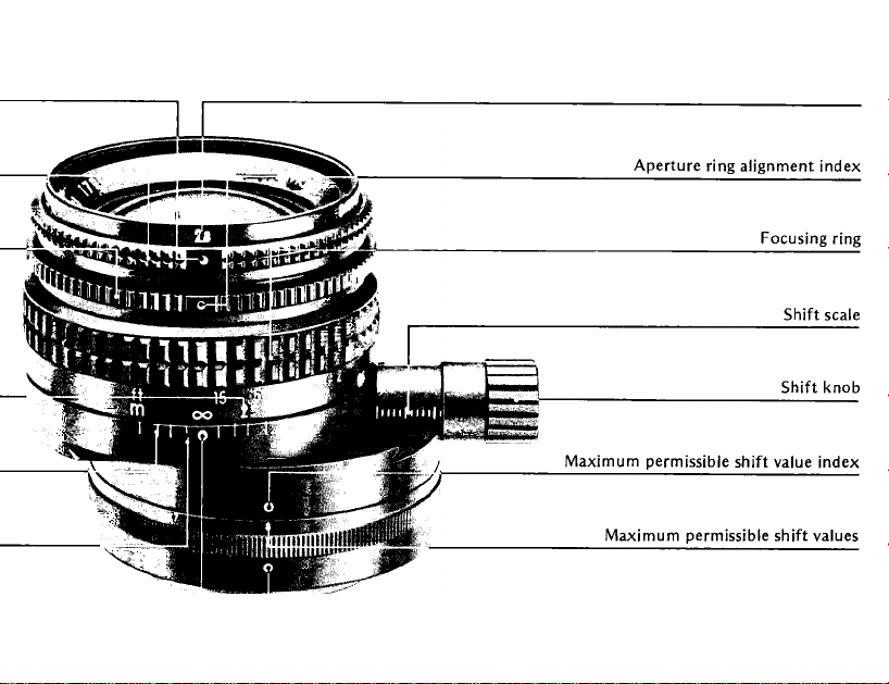
Ape rtu re sc ale
J L
Mounting index
Page 5

CONTENTS
Foreword........................................4
Mounting the lens
Setting the aperture. . . ...............
Stop-do^ measurement
Focusing
Depth of field
Shift and rotation movement. . .10
Maximum permissible shift... 11
Framing........................................12
Panoramas...................................16
Depth of field tables....................20
Close-up tables
Features/specifications
........................................
.........................
.............
..............................
...........................
..............
22
23
5
6
7
8
9
Page 6

FOREWORD
The PC-Nikkor 35mm f/2.8 is a retrofocus-type
perspective control (PC) lens with an optical
construction of 7 elements in 7 groups. The
image circle of this lens is wider than regular
35mm wideangle lenses providing a covering
angle of 78°; thus image quality is insured even
when the lens is shifted. The lens barrel can be
shifted up to 11mm off-axis and rotated 360°
with click-stops every 30° for complete image
control. The PC-Nikkor is ideally suited for
architectural and commercial photography,
enabling the photographer to properly frame
the subject without tilting or angling the
camera—and the photographer has the added
convenience of thru-the-lens viewing and meter
ing for greater ease of operation. It is also
possible to take panoramic shots.
If used with a Nikon camera having inter
changeable focusing screens, the Type E or E2
with its etched horizontal and vertical lines is
recommended. All aberrations have been well
corrected, especially coma and curvature of
field, so that image quality is truly outstanding.
Page 7
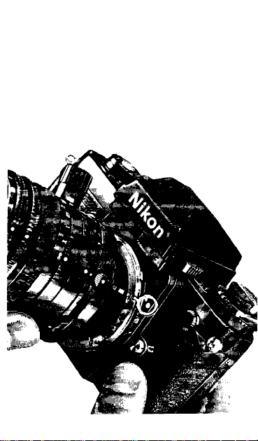
MOUNTING THE LENS
Page 8

The PC-Nikkor 35mm f/2.8 mounts on all Nikon and
Nikkormat cameras. To mount the lens, position it in
the camera’s bayonet mount so that the mounting
index dots on the lens and the camera are aligned.
Then, grasp the milled surface of the mounting ring
and twist the lens counterclockwise until it clicks and
locks into place. (See “Stop-Down Measurement” on
page 6 for metering procedures.)
To remove the lens from the camera body, press the
lens release button on the camera and, keeping the
button depressed, twist the lens clockwise.
To use the PC-Nikkor as a normal 35mm lens without
using the perspective control feature, rotate the lens
barrel so that the shift scale faces up. Then, if neces
sary, turn the milled shift knob until the distance scale
index dot is aligned with the shift scale index dot.
f
Page 9
SETTING THE APERTURE
Page 10

The PC-Nikkor is provided with a manual diaphragm
operable from f/2.8 to f/32 and a spring-loaded preset
ring to aid in setting the diaphragm quickly to the
shooting aperture; a total of eight click-stop positions,
at full-stop intervals, makes for precise placement of
the preset ring. Also, identical sets of f/numbers are
engraved on opposite sides of the front rim of the lens
to facilitate operation when the lens is used inverted.
To set the aperture, the following procedure is recom
mended: Press the preset ring toward the camera body
and turn it until the f/number setting corresponding
to the desired shooting aperture is aligned with the
ring’s index dot; then release the ring and it will spring
outward and lock in place. Note that the preset ring,
once set, limits the travel of the aperture ring so that
the diaphragm can be set easily and quickly from the
full aperture viewing position to the shooting aperture
without the need for checking the scale during stopdown operation.
Page 11

Stopped-Down Measurement
The PC-Nikkor lens must be stopped down to deter
mine the exposure when used on TTL cameras.
Because the finder image progressively becomes darker
as the lens is stopped down, you should focus first
before taking a meter reading.
It is important to note that exposure measurement
must be performed before the lens is shifted; should
measurement be performed after shifting, erroneous
meter readings may occur. With automatic exposure
cameras, such as the Nikon F3, FE2 or FE use the
camera’s memory lock to retain the correct shutter
speed before shifting the lens for the final picture
composition. Since the Nikon EM doesn’t have a
memory lock, the correct exposure cannot be obtain
ed while shifting.
Page 12

Page 13

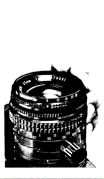
FOCUSING
Page 14

The aperture and preset rings of the PC-Nikkor enable
focusing at full aperture for the brightest viewfinder
image, with rapid setting of the diaphragm to the pre
set shooting aperture. Having set the preset ring to the
desired aperture setting, focus as follows: Turn the
aperture ring to the f/2.8 setting to open the diaphragm
fully for focusing (photo 1); then turn the focusing
ring until the image on the focusing screen is in sharp
focus (photo 2). Before releasing the shutter, turn the
aperture ring until It contacts the preset ring and can
no longer be turned—the diaphragm is now at the pre
set shooting aperture (photo 3).
Note: The Type E2 focusing screen is highly recommended
for use with FA/FE2/FM3 Nikon cameras and the Type E for
use with F/F2/F3/FE Nikon cameras. The vertical and hori
zontal lines etched on the screen help you to properly align
the camera for proper perspective correction of the image.
Page 15

Depth of Field
Depth of field refers to the zone of acceptable focus
extending in front of and behind the plane of sharpest
focus. Within this zone, image blur is negligible and
everything can be considered as being in sharp focus.
To observe the depth of field with the PC-Nikkor lens,
it is necessary to manually set the diaphragm to the
required shooting aperture; for procedures, refer to
“Setting the Aperture” on page 6.
Depth of field can also be determined by reading the
color-coded depth-of-field indicators engraved on the
lens barrel opposite the distance scale. Each pair of
colored lines corresponds to an f/number of the same
color engraved on the lens front rim. To find the depth
of field at a particular aperture, focus the lens on the
subject and then check the numbers on the distance
scale opposite the colored lines that match the color
of the preset shooting aperture setting.
When in doubt about depth of field for a critical
shooting situation, refer to the tables on page 20 and
21 of this instruction manual.
Page 16

Recommended Focusing Screens
Various interchangeable focusing screens are
available for F3- and F2-series cameras to suit
any type of lens or picture-taking situation.
Those which are recommended for use with
your lens are listed below. For screens used
with Nikon cameras other than F3- and F2series cameras (e.g., Nikon FA, FE2, FM2 and
FE), refer to the column for F3-series cameras.
For the K2, B2 and E2 focusing screens, refer
to the columns on the K, B and E screens,
respectively. For details, also refer to the spe
cific focusing screen’s instruction sheet.
Screen
a/l|b c D E Gl G2 G3 G4
Camera^"^
F3
F2
3
A
HI
H2 H3 H4
j|k/p M R
lll#l
6
<1
a
o = Excellent focusing
• = Acceptable focusing
The split-image rangefinder, microprism
or cross-hair area is dim. Focus on the
surrounding matte area.
E]= Exposure measurement via stop-down
method
Blank means not usable.
Page 17

SHIFT AND ROTATION MOVEMENT
The front part of the PC-Nikkor shifts up to 11mm
from the center in a plane parallel to the film, and
the whole lens mount rotates through a full 360°.
By combining the parallel shift with the rotation
movement of the lens, an infinite variety of adjust
ments can be made.
To shift the lens, turn the knurled shift knob. The
knob should always be turned so that it is facing away
from the direction in which the lens is to be shifted.
The shift scale shows the degree of shift in millimeters.
When the shift scale is facing upward, the lens can be
shifted 11 mm to the right of center. In order to shift
the lens in other directions, simply rotate the whole
lens mount, stopping at one of the 12 click-stop
settings provided at 30° intervals, or choosing a
desired intermediate position. By combining these two
movements, the lens can be shifted up to 11mm from
the center in any direction.
10
Page 18

Maximum Permissible Shift
Depending on the direction of shift, however, there is
a maximum permissible shift, beyond which distortion
and/or vignetting may occur in the picture corners,
because the film format is rectangular while image area
produced by the lens is circular. The amount of maxi
mum permissible shift (7, 8 or 11) is indicated in
millimeters at each click-stop on the lens barrel. The
diagrams at right show the limits based on the direc
tion of shift.
Note: When you use a Nikon polarizing filter in combination
with a lens hood, vignetting will occur even at the maximum
permissible amount of shift at each click-stop.
Page 19

Diagram 2
11
Page 20

FRAMING
As long as the camera is held in a position parallel to
the subject when shooting, it reproduces scenes more
or less as the eye sees them, with no unpleasant per
spective distortion. However, shooting from this
position often produces unbalanced composition,
since the camera is usually used close to ground level.
Much unwanted foreground is included in the lower
half of the frame, while part of the main subject, for
instance the top of a building, is excluded (Fig. 1).
12
Page 21

Page 22

Inevitably, the camera must be tilted in order to
include the top of the building and minimize the
foreground (Fig. 2). But with the camera tilted, the
plane of the film is no longer parallel to the subject,
and because the image size varies according to subject
distance, the nearer parts of the subject are repro
duced on a scale larger than those farther away.
The sides of the building appear to converge, as if the
building were leaning back or falling. Similar distor
tion occurs in horizontal lines when photographing a
long line of buildings at an angle.
Note: Meter with the camera aimed for the general final com
position; this is shown by Fig. 2 on this page.
Page 23

Page 24

FRAMING — continued
The PC-Nikkor’s shift and rotation movements enable
you to create balanced composition without tilting
the camera, so that the film remains parallel to the
plane of the subject (Fig. 3).
To photograph a tall building, hold the camera
parallel to the plane of the building. Rotate the lens
mount until the milled knob points downward, and
sight the subject on the focusing screen. Now turn the
milled knob until all of the building is visible and
unwanted foreground area is trimmed away, checking
to be sure that the adjustment is within the permissi
ble shift area (see page 11).
If you must exceed the permissible shift adjustment
in order to include all of the desired subject, try to
compose the picture so that any peripheral distortion
will occur in unimportant areas, such as sea, sky or
earth. Use the same technique to
Page 25

Page 26

Page 27

PANORAMAS
The shift movement of the PC-Nikkor
can also be used for making panoramic
pictures by joining exposures. Its advan
tage over the normal lens mounted on
panoramic equipment is that it enables
you to maintain exactly the same film
plane in both exposures so that the fin
ished photographs will match exactly.
With the ordinary lens, the camera must
be moved after the first exposure in order
to take in a new arc of the horizon. This
movement changes the film plane, so that
vertical and horizontal lines in the subject
make new and different angles with the
film. As a result, no two photographs will
ever match perfectly when joined.
16
Page 28

Page 29

Page 30

To take panoramic shots, place the lens
in normal position, shift scale facing
upward, and operate the milled shift
knob to shift the lens as far to the left as
possible. Compose, focus, and shoot. With
out moving the camera, wind the film
advance lever to advance the film one
frame, and rotate the lens mount through
180° so that the shift scale faces straight
down. Now make the second exposure.
17
Page 31

PANORAMAS —continued
These two exposures together cover a horizontal
angle of 78° without turning the camera, 4° more
than the range of a 24mm wideangle lens, and with
the added advantage of larger image size. The table
below gives a comparison of the angles of various
wideangle lenses and the PC-Nikkor panorama range.
In making a vertical panorama, a 65° vertical angle
can be covered using the extreme rise and fall shifts,
with the camera still in the horizontal position. The
overlapping area is least when two pictures are
matched vertically.
Caution; Extreme care is necessary when taking panoramic
shots to avoid camera movement, since even a slight movement
between exposures will result in some distortion and photo
graphs will not join exactly. For best results mount the camera
on a tripod.
Nikkor lens Horizontal picture a ngle
20mm f/2.8
24m m f/2.8 74“
28m m f/2
35m m f/1.4
35m m
Vertical conne ction 53“
PC
Horizontal connection
18
84“
64“
53“ 37“
78“ 37“
Vertical picture ang le
62“
53“
45“
65°
Page 32

When making enlargements, be sure
that the negative is absolutely parallel
to the easel to prevent distortions.
All of the focusing adjustments on
the enlarger should be maintained
constant from one exposure to the
next. When the prints are removed
from the washer, insert them in a
rotary dryer facing the same direction.
Overlap ped a rea for vertica l shi fting
Page 33

24mm
PC-Nikkor 35mm
Ordinary 35mm
T
Page 34

DEPTH-OF-FIELD TABLES
2.8
4.0
5.6 8.0
X
1.0
1.3
1.5
^'5rX’'0f6
-l-X'
11.0 16.0 22 .0 3 2.0
X-X'
T2f-T3f r2'-r4f;
"fxx
1'3f-r9"
16 4
ril^'lr4^"
16 16
(ft)
X-X'
Rep roduction
ratio
1/5.4
1/7.6
1/9.7
20
2.0
3.0
<-s.r
5.0
15.0
ir5"-21'9'' 10’5 "-27'1"
oo 46’—CO
nii;-2T'
32'-oo
riof;-2'2r
r9f-2'3'’ rB|-2.f 1/14
2.B|-3.f 27|-3'6’’ 2’6r_3'8f
3'nf-6'10f; 3'3^-W r
9'3"_40'2 "
23'~ oo
16'— c» 12'-oo 8 '—CO
8'-152'6”
6'10 "-oo
4
5'6"-oo
-XX'
4'6"— c» 3'6"— oo 1/124
1'11 —— 7'7—
16 16
2'6-y-oo
2'1i 4--21'4^
2 4
4
6'— oo 4' — oo
1/22
1/39
l/oo
Page 35

X
0.30
0.298-0.302
0.35
0.346-0.354
0,40
0.395-0.406
0,50
0.490-0.511 0.486-0,515
0.70
0.677-0.725 0.668-0.736
1,0
0.948-1.06 0,927-1.09
2.0
1.78-2.29 1.70-2.44
00
14-00 10-OO
2.8
4.0 5.6
0.297-0.303 0.296-0.305 0.294-0.307
0..345-0.355
0.392-0.408 0.389-0.412 0.385-0.417 0.380-0.424
0.343-0.358
0.480-0,522
0.656-0.752 0.638-0,778 0.619-0.812
0.902-1.13
1.60-2.69
0.340-0,361 0.336-0,365
0,473-0,532 0.463-0.545
0.866-1.19
1-48-3.16
7-00 5 — 00
8.0
11.0 16.0
0.292 - 0.309 0.288-0.314 0.284-0.319
0.331-0.373 0.324-0.383
0.371-0.435
0.449-0.569 0.433 — 0.602
0.588-0.878
0.825-1.29 0.766 -1.49 0.707-1.84
1.35-4.08 1.18-8 .01
4-00 3—00
(m)
22.0 32.0
0.278-0.329 1/5.3
0.314-0.401 1/6.7
0.362-0,451 0.3 48-0.481
0.410-0,667
0.557-0.976
1.03-oo
0.512-1.210 1/16
0.629-3.15 1/2 5
2-00
0.86— oo
1 — 00
Reproduction
ratio
1/8.1
1/11
1/52
l/oo
21
Page 36

CLOSE-UP TABLES
Close-up attachments
Close-up Lens No.O
Close-up Lens No.1
Close-up Lens No.2 1/9.4-1/3.5
Close-up Lens No.1-1-N o.2
12 Rin g
K Ring Set
PK Ring
Bellows Attachmen t PB-4, PB -5
Bellows Attachmen t PB-6 1.3-5.7
Micro-Co py Stand PB-6M
Extension Bellows PB-6E
Rep ro-Copy O utfit Mode l PF-2, 3, 4 1 /21-1 /5,5 19,5x29 .3-5.2x7.7
PN Ring
Rep roduction
ratio
1/39-1/4.8 36,8x5 5.3-4 .5x6.8 (93.6x 140-11.5x 17,2) 60 ,1-11 .2 (153-2 8.5)
1/19-1/4.3
1/6.3-1/3.0 5.9x8.9-29x4.3 (15.1X22.6-7.3X1 0.9) 13.8 -9,0
1/2.6-1/1.8
1/6.2-1.5 5.9x8.8-0.64x0.96
1/4.5-1.6
1.2-5.1 0-80x1.2-0.18x0.28 (2.0x 3.0-0 .47x0.70)
1.3-4.4
1.3-7.0
1.5-1.6 0.65X0.98-0.58X0.87 (17x2.5-1.5x2.2)
Lens in n orma l pos ition
Unit: inch (cm
Sub ject field
17.6x26.3-4.0x6.0 (44.6x66.9-10.2x15 .4) 31.2-10.6 (79.3-26.8)
8.8x13.3-3.3x5.0
2,4x3.7-1,7x2.5
4.3x6.4-0.61x0.91 (10.9X1 6,3-1 .5X2.3) 10.8-7.2 (2 7,5 -18.2)
0,71x1.1-0.16x0,25 {1,8x2 .7-0.42x0.63) 7.0-12.5
0.71 Xl.l-0,22x0.33 (1 .8X2,7-0.55X0.83) 7.0-10.6 (17.8-26.9)
0,71x1.1-0,14x0.20
(22.4X33 .7-8.4x12.7)
(62x9.3-4,2x6.3)
(15.0x22.5-1.6x2.4)
(1.8 x2,7-0,34x0.52)
(49.6 x 74.4-13.1x1 9.6) 33.6-1 1.8 (8 5.3-3 0.0)
Focused dista nce
18.0-9.6 (45.7-24.3)
(34.9-22.9)
8-3-74
(21.1-18.7)
13.2-7.1 (33.5-18,1)
6,9-11,6
(17.6-29.5)
(17.8-31.7)
7.0-21.4 (17.8-54.4)
(18.0-18.4)
7.1-7.3
Close-up attachments
Bellows Attachmen t PB-4, PB -5 2.7-6.7
Bellows Attachmen t PB-6
Slide-Copy Adapter PS-4, PS -5
Slide-Copy Adapter PS-6
Micro-Co py Stand P8-6M 2,4-4.4
Extension Bellows PB-6E
22
Lens in revers e position
Rep roduction
ratio
2,4-5.5 0.39x0.58-0.17x0,26
2.7-67
2.4-4.3 0.39 x 0,58 - 0.22 x 0.33 (0.99x 1,5-0 .56x0.84) 8,1-10,5 (20.6-26,6)
2,4-11.8 0.3 9 x 0 .58 - 0.08 x 0.1 2 (0.99x1.5 -0.20 x0.30)
0.35 x 0.52 - 0.14 x 0.21 (0.88x 1.3-0 ,36x0,54) 8.5-13.8 (21.5-34,9)
0,35x0.52-0,14x0.21 (0.8 8X1,3-0.36X0.54)
0.39x0.58-0,22x0.33 (0.99x1.5-0.55x0,83) 8.1-10.6 (20.6-26.9)
Sub ject field Focused dista nce
(0.9 9x1.5-0.44x0.66) 8.1-12.1 (20.6-30.8)
8,5-13.8
8.1-21.0 (20,6-53.4)
(21.5-34,9)
Page 37

FEATURES/SPECIFICATIONS
Focal length: 35mm
Maximum aperture; f/2.8
Lens construction: 7 elements in 7 groups
Picture angle: 62°
Covering power: 78°
Distance scale: Graduated in meters and feet
from 0.3m (1 ft) to infinity (°°)
Aperture scale; f/2.8—f/32
Diaphragm: Manual type with preset ring for
convenience when setting the diaphragm to
the shooting aperture
Exposure measurement: Stop-down method
Lens rotation: Lens optics rotate 360° for
perspective control adjustments in any
direction; click-stops provided at each 30
of rotation; maximum permissible shift
values engraved at each click-stop position
Lens shift; Special mount enables up to
11 mm off-center shift for perspective
control; shift adjustments via milled knob
at side of lens; shift scales provided with
graduations at 1mm intervals
Mount: Nikon bayonet type
Page 38

Attachment size: 52mm (P = 0.75mm)
Dimensions: Approx. 62mm x 61.5mm exten
sion from flange; 66mm long (overall)
Weight: Approx. 320g
Accessories
Supplied
52mm snap-on front
lens cap
Rear lens cap LF-1
Hard lens case CL-34A
Optional
52mm screw-in lens
hood HN-1
52mm screw-in filters
Lens pouch No. 61
23
Page 39

No reproduction in any form of this manual, in
whoie or in part (except for brief quotation in
criticai articles or reviews), may be made without
written authorization from NIKON CORPORATION.
Nikon
NIKON CORPORATION
FUJI BLDG., 2-3, MARUNOUCHI 3-CHOME, CHIYODA-KU,
TOKYO too, JAPAN
PHONE: 81-3-214-5311 TELEX: J22601 (NIKON) FAX: 81-3-201-5856
Page 40

Printed in Japan 8&108-e04
 Loading...