


FCA54001-R.3567.A
配布許可印
作成承認印
FCA54001
FCA54201
REPA I R M A N UAL
Copyright © 2002 by Nikon Corporation.
All Rights Reserved.
無断転載を禁ず ! !
Printed in Japan March 2002
Nikon
NIKON CORPORATION
Tokyo, Japan

FCA54001-R.3567.A
- One Touch Zoom 90s AF -
SPECIFICATIONS
Model·Lens·Automatic focus ・・・・・・・・・・・・・・・・・・・・・・・・・・・・・・・・・・・・・・・・・・・・・・・・・・ M1
Shutter·Finder ・・・・・・・・・・・・・・・・・・・・・・・・・・・・・・・・・・・・・・・・・・・・・・・・・・・・・・・・・・・・・ M1
Speed light function·Self-timer ・・・・・・・・・・・・・・・・・・・・・・・・・・・・・・・・・・・・・・・・・・・・ M2
Film speed·Film advance ・・・・・・・・・・・・・・・・・・・・・・・・・・・・・・・・・・・・・・・・・・・・・・・・・・・・ M3
Date function·Power supply ・・・・・・・・・・・・・・・・・・・・・・・・・・・・・・・・・・・・・・・・・・・・・・・・・ M4
Error display ・・・・・・・・・・・・・・・・・・・・・・・・・・・・・・・・・・・・・・・・・・・・・・・・・・・・・・・・・・・・・ M5
AF step table ・・・・・・・・・・・・・・・・・・・・・・・・・・・・・・・・・・・・・・・・・・・・・・・・・・・・・・・・・・・・・・ M6
Program graph ・・・・・・・・・・・・・・・・・・・・・・・・・・・・・・・・・・・・・・・・・・・・・・・・・・・・・・・・・・・・・・ M7
AE coupling graph WIDE ・・・・・・・・・・・・・・・・・・・・・・・・・・・・・・・・・・・・・・・・・・・・・・・・・・・・・ M8
AE coupling graph TELE ・・・・・・・・・・・・・・・・・・・・・・・・・・・・・・・・・・・・・・・・・・・・・・・・・・・・・ M8

FCA54001-R.3567.A
- M1 • One Touch Zoom 90s AF -
1.SPECIFICATION
(1) Model
·Zoom lens built-in automatic focus 35mm AE lens shutter Flash built-in compact camera
(2) Picture size
·24mm×36mm
(3) Zoom photography lens
·Focal length W 39.60mm ~ T 86.80mm
·FNO W F4.97 ~ T F10.90
·Lens construction FC 3 groups and 3 lenses RC 2 groups and 2 lenses
(4) Automatic focus
·Infrared active triangular distance measurement method
·Distance measurement step number: AF step number 26+Forced innity step+Macro step
·Focus lock function is prepared. (Release button pre-release function)
(5) Focusing range (Focusing range is the distance from the whole surface of the front barrel.)
·W 0.745m ~∞ (0.8m from the lm surface)
·T 0.710m ~∞ (0.8m from the lm surface)
·SM
(6) Shutter type
·Electromagnetic drive (Step motor) program electronic shutter
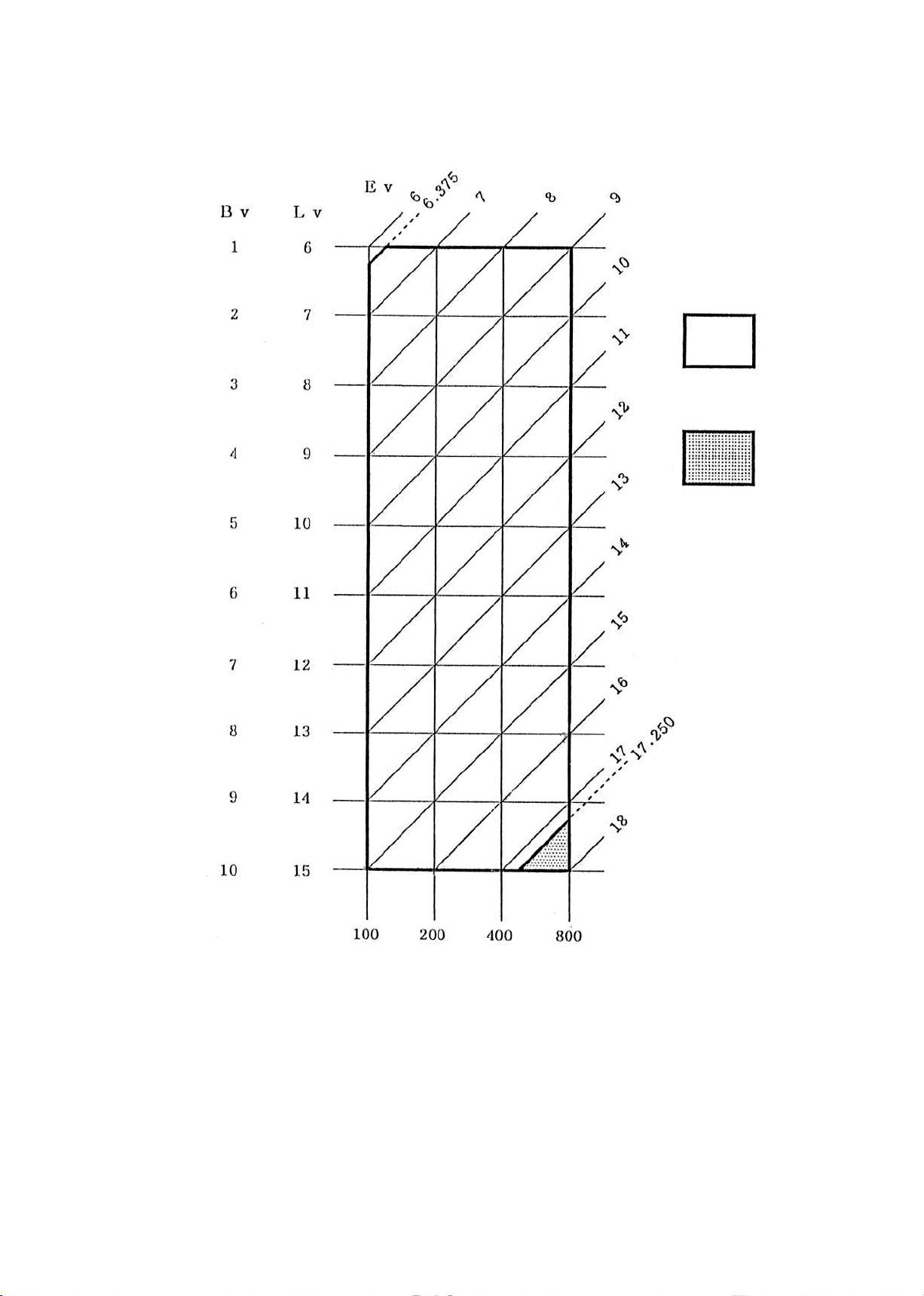
·AE coupling range WIDE Ev6.0: 1/1.85 sec ~ Ev16.0: 1/250 sec
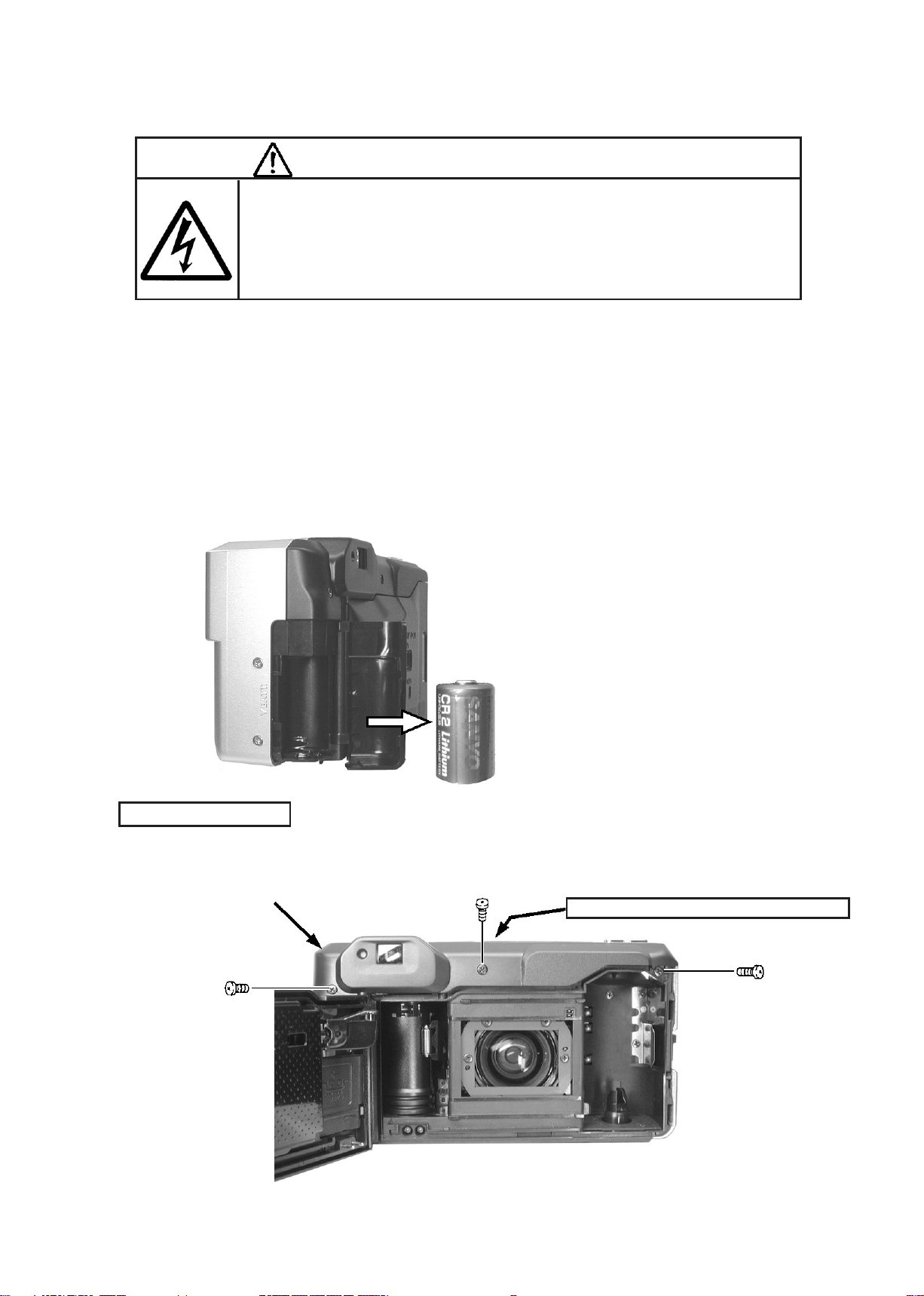
TELE Ev6.0: 1/ 1.98 sec ~ Ev18.0: 1/250 sec
·FM coupling range WIDE F4.97 ~ T F16 (WIDE conversion)
·Daytime sync control is the small aperture priority electronic FM which is determined by
slope ash or mountain-top sync.
(7) Finder
·Real image zoom nder
Field of viewnder 80% or more and less than 100% in vertical and horizontal directions
Magnication W 0.336 times,T 0.686 times
Diopter -0.7 diopter
Eye point 14.4mm from the appearance surface (16mm from the lens surface)
Information in nder: AF target mark
Near distance compensation mark: at 0.7m (TELE)

FCA54001-R.3567.A
- M2 • One Touch Zoom 90s AF -
(8) Speed light mode
·Normal mode (1 ~ 5 is changed by the mode button.)
1. Auto
2. Distant view mode (with Flash prohibition)
3. Flash prohibition
4. Forced ash
5. Slow sync (with Forced ash)
·Macro mode
1. The lens barrel is moved to W end by pressing the macro button.
2. The photography lens is set to the nearest distance.
3. The macro button blinks in orange. (4Hz)
4. The speed light mode is changed to “Forced ash ”.
(9)
Self-timer
Red eye reduction
·Press the self-timer button to set the red eye mode, and the high pressure lamp is turned
on for 1 second before opening.
·The red eye relief mode can be used with each of speed light modes at the same time.
In the ash prohibition mode, the high pressure lamp should not be turned on.
Self-timer
·Electronic control self-timer: Release occurs after 10 seconds since start.
·How to operate: Press the self button on the upper surface of the camera. After the
self-timer is displayed in LCD, press the release button.
·Operation display: 1Hz for 7 seconds. For another 3 seconds, it is turned on.
(The red eye lamp is used.)
·How to release: If releasing the self-timer during operation, set the main switch button
to “OFF ”.
Mode change order
·OFF?Red eye mode?Red eye+Self-timer
(10) Speed light
·GNo: 10 (ISO100·m)
·Recycling time: Approx. 7 seconds

FCA54001-R.3567.A
- M3 • One Touch Zoom 90s AF -
(11) Release mechanism
·Electromagnetic release by the conductive rubber contact
·Pre-release function
AF lock
AE lock
Photography possible display: The green LED is turned on at the left of the nder on the
rear of the camera.
BC display: The picture of the battery mark is displayed in LCD on the upper surface of the
camera.
(12)
Setting of film speed
·ISO: The lm speed is automatically set by DX code.
·For other lms except DX, the lm speed is set to “ISO100 ”.
·ISO100: 25, 32, 40, 100, 125, 160, No DX code
200: 50, 64, 80, 200, 250, 320
400: 400, 500, 640, 1600, 2000, 2500
800: 800, 1000, 1250, 3200, 4000, 5000
(13) Film advance
·The 1st frame to be photographed is automatically set by closing the camera back.
·1st frame is wound by pressing the release button.
·Automatic rewinding is done when the lm end is detected.
·If you hope to rewind the lm halfway, press the MU button on the upper surface of the
camera.
·After the lm end is detected or after the MU button is pressed, the lens barrel is
automatically housed and rewinding starts.
·The lm counter is displayed in LCD on the upper surface of the camera. (Coupling operation
of forward calculation and backward calculation at rewinding)
(14) Film advance quantity
·Approx. 15 of 24-exposure lm rolls: when speed light 50% is used at normal temperature
(15)
Auto. power OFF
·If operation is not done by the operating button after the main switch is turned on, the
lens barrel is automatically pushed in after approx. 3 minutes and the power is turned off.
·All the modes except the red eye reduction mode are reset.
(16) Information in LCD
·Battery condition (BC display)
Warning cannot be used.
·Frames to be photographed (It is displayed with the counter numerals.)
·Remaining frames to be rewound (It is displayed with the counter numerals.)
·Rewinding completion display (It is displayed with the counter numerals.)
·Self-timer display
·Speed light photography mode display

FCA54001-R.3567.A
- M4 • One Touch Zoom 90s AF -
(17) Lens cover
·The lens cover is opened and closed between the push-in position and W end.
(18) Date function
·LCD display quartz digital clock is built in.
·Auto. calendar from 1998 to 2049.
·Date copy display is changed by 5 modes.
1. Year/month/day mode → 2. Day/hour/minute mode → 3. Copy prohibition mode →
4. Month/day/year mode → 5. Day/month/year mode
·Lithium battery CR2025 (1 pc.) is used as a power supply which is separate from the power
supply for the camera.
(19) Power supply of camera
·Lithium battery CR2 (3V), 1 pc, is used.
(20) Camera size
·117 (width)×64.4 (height)×49.2 (depth) mm
·117 (width)×64.4 (height)×52.8 (depth) mm [QD specication]
(21) Weight
·215g
·225g [QD specication]

FCA54001-R.3567.A
- M5 • One Touch Zoom 90s AF -
(22) Error display
(22) Error display How to release
1 Lens barrel NG n 2 When the lens barrel is in the middle of WIDE and TELE,
press lightly the release button, press the zoom button,
main switch button and MU button and open and then close
the camera back. Consequently the initial condition is set.
When the lens barrel is in the push-in position, press the
main switch button, open and then close the camera back
and press the MU button. Consequently the initial
condition is set.
If the same error is displayed though the above procedure is
performed, disassemble and repair the camera.
2 Shutter NG n 3
n 1
3 FFS NG
4 1 frame advance NG
5 Rewinding NG
Load the battery again, open and then close the camera
back, press the MU button and press lightly the release button.
Consequently the initial condition is set.
If the same error is displayed though the above procedure is
performed, disassemble and repair the camera.
If FFS fails, the operation stops just under the condition and
“E” blinks.
The error condition is released by opening the camera back.
If 1 frame advance fails, automatic rewinding starts and, when
rewinding is ended, “0” blinks.
The error condition is released by opening the camera back.
If an accident is caused during rewinding and so emergency stop
occurs, the counter blinks at that time to show that the camera
is in an abnormal condition.
Open the camera back in a dark box, take out the lm and close
the camera back.
FCA54001-R.3567.A
- M6 • One Touch Zoom 90s AF -
MACRO
Lens stop
Front lens group
forward length(mm)
Forced
innity
AF innity
Step distance (m)
Change-over
distance (m)
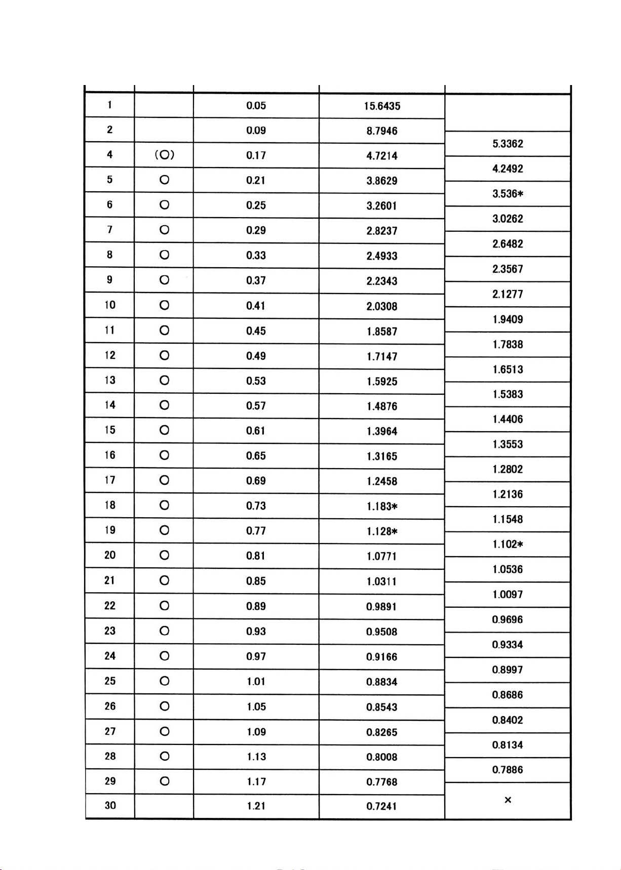
[AF step table]
Step

FCA54001-R.3567.A
- M7 • One Touch Zoom 90s AF -
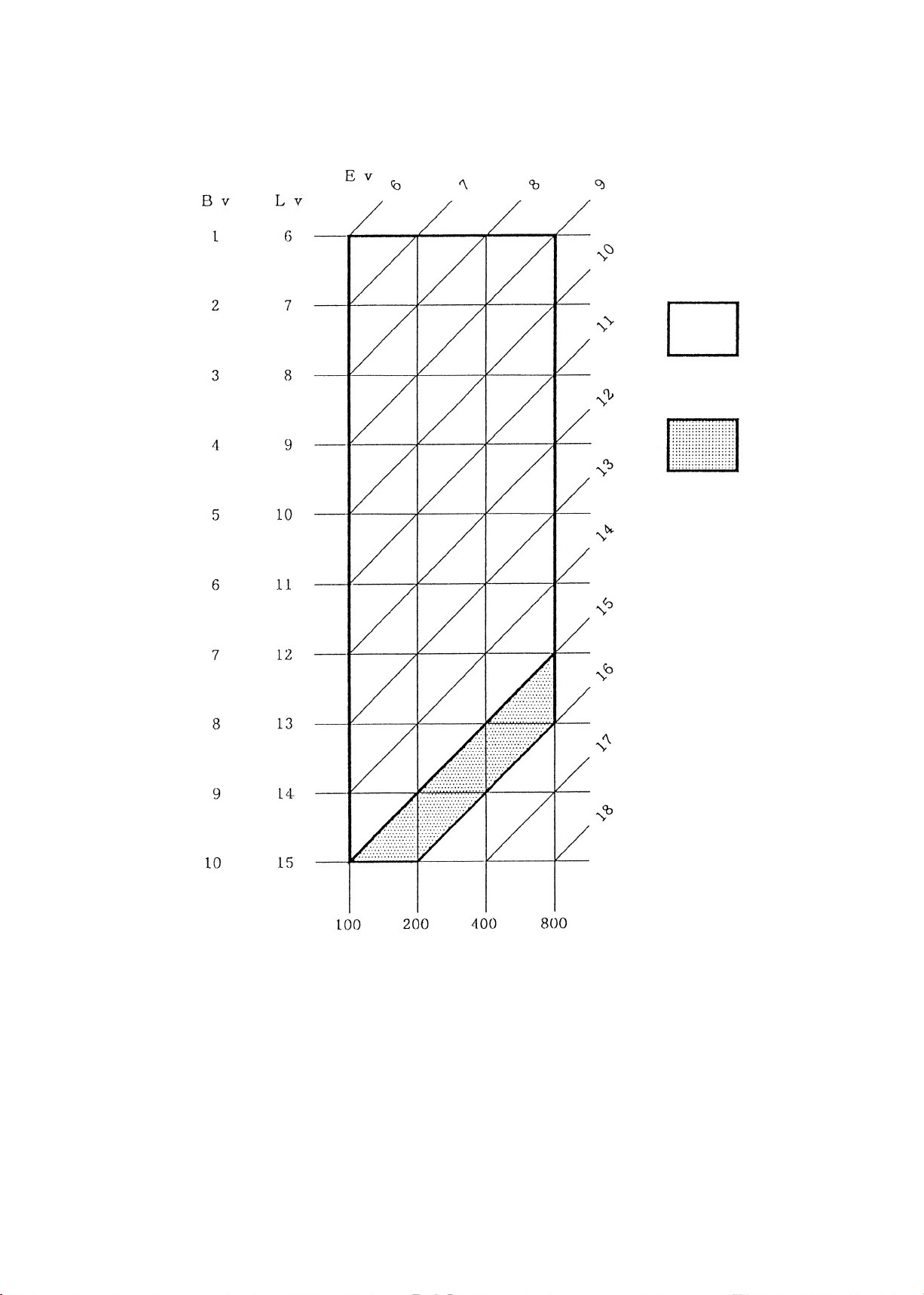
[Program graph]
F4.97
F10.90
●: Speed light ash point (WIDE) ○: Speed light ash point (Equivalent to TELE)
■: Slow sync (WIDE) □: Slow sync (Equivalent to TELE)
☆: Macro mode (Equivalent to F32)
·In other modes except the above, control is done according to the program curves in the
graph.
·Converted values should be used for TELE.
·The above values should be expressed in consideration of 0.5 over-shift.
·The ash point should be mentioned at Ev 10.125 (WIDE conversion) for WIDE side and Ev
13.875 (WIDE conversion) for TELE side.
·In the slow sync mode, only under the condition of Bv ≦ 1, Ev ≧ 5.00, the above expressed
control is done.
FCA54001-R.3567.A
- M8 • One Touch Zoom 90s AF -
[AE coupling graph] WIDE
Coupling range A
Coupling range B
ISO value
FCA54001-R.3567.A
- M9 • One Touch Zoom 90s AF -
[AE coupling graph] TELE
Coupling range A
Coupling range B
ISO value

FCA54001-R.3567.A
- One Touch Zoom 90s AF -
DISASSEMBLING/ASSEMBLING/ADJUSTMENT
1. DISASSEMBLING
Removal of side cover ・・・・・・・・・・・・・・・・・・・・・・・・・・・・・・・・・・・・・・・・・・・・・・・・・・・・・・ D1
Removal of front cover ・・・・・・・・・・・・・・・・・・・・・・・・・・・・・・・・・・・・・・・・・・・・・・・・・・・・・ D2
Discharge of main condenser ・・・・・・・・・・・・・・・・・・・・・・・・・・・・・・・・・・・・・・・・・・・・・・・・ D3
Removal of camera back ・・・・・・・・・・・・・・・・・・・・・・・・・・・・・・・・・・・・・・・・・・・・・・・・・・・・・ D3
Removal of AF unit ・・・・・・・・・・・・・・・・・・・・・・・・・・・・・・・・・・・・・・・・・・・・・・・・・・・・・・・・・ D4
Removal of nder ・・・・・・・・・・・・・・・・・・・・・・・・・・・・・・・・・・・・・・・・・・・・・・・・・・・・・・・・・・ D5
Removal of zoom mechanism unit ・・・・・・・・・・・・・・・・・・・・・・・・・・・・・・・・・・・・・・・・・・・・・ D6
Removal of speed light unit ・・・・・・・・・・・・・・・・・・・・・・・・・・・・・・・・・・・・・・・・・・・・・・・・ D6
Removal of lens barrel ・・・・・・・・・・・・・・・・・・・・・・・・・・・・・・・・・・・・・・・・・・・・・・・・・・・・・ D7
Removal of lm advance mechanism unit ・・・・・・・・・・・・・・・・・・・・・・・・・・・・・・・・・・・・・ D7
Disassembly of lens barrel ・・・・・・・・・・・・・・・・・・・・・・・・・・・・・・・・・・・・・・・・・・・・・・・・・ D8
2.ASSEMBLING/ADJUSTMENT
Shutter·FC lens ・・・・・・・・・・・・・・・・・・・・・・・・・・・・・・・・・・・・・・・・・・・・・・・・・・・・・・・・・・・・ A1
RC lens·Straight guide A ・・・・・・・・・・・・・・・・・・・・・・・・・・・・・・・・・・・・・・・・・・・・・・・・・・・ A2
Lens barrel A·Lens barrel B・・・・・・・・・・・・・・・・・・・・・・・・・・・・・・・・・・・・・・・・・・・・・・・・・・ A3
Main barrel·Straight guide B ・・・・・・・・・・・・・・・・・・・・・・・・・・・・・・・・・・・・・・・・・・・・・・・ A4
Leaf switch·Driving gear·Relay FPC ・・・・・・・・・・・・・・・・・・・・・・・・・・・・・・・・・・・・・・・・・ A5
Body unit ・・・・・・・・・・・・・・・・・・・・・・・・・・・・・・・・・・・・・・・・・・・・・・・・・・・・・・・・・・・・・・・・・・ A6
Film advance mechanism unit ・・・・・・・・・・・・・・・・・・・・・・・・・・・・・・・・・・・・・・・・・・・・・・・・ A7
Zoom mechanism unit ・・・・・・・・・・・・・・・・・・・・・・・・・・・・・・・・・・・・・・・・・・・・・・・・・・・・・・・・ A8
Film advance mechanism unit installation·Lens barrel unit installation・・・・・・・ A9
Zoom mechanism unit installation·Speed light unit installation・・・・・・・・・・・・・・・ A10
Finder unit installation ・・・・・・・・・・・・・・・・・・・・・・・・・・・・・・・・・・・・・・・・・・・・・・・・・・・ A12
AF unit installation ・・・・・・・・・・・・・・・・・・・・・・・・・・・・・・・・・・・・・・・・・・・・・・・・・・・・・・・ A13
Wire processing ・・・・・・・・・・・・・・・・・・・・・・・・・・・・・・・・・・・・・・・・・・・・・・・・・・・・・・・・・・・・ A14
Finder positioning·Front cover ・・・・・・・・・・・・・・・・・・・・・・・・・・・・・・・・・・・・・・・・・・・・・ A15
Back focus inspection and adjustment ・・・・・・・・・・・・・・・・・・・・・・・・・・・・・・・・・・・・・・・ A16
AE inspection ・・・・・・・・・・・・・・・・・・・・・・・・・・・・・・・・・・・・・・・・・・・・・・・・・・・・・・・・・・・・・・ A19
AF inspection and adjustment ・・・・・・・・・・・・・・・・・・・・・・・・・・・・・・・・・・・・・・・・・・・・・・・ A19
Side cover·Barrier ・・・・・・・・・・・・・・・・・・・・・・・・・・・・・・・・・・・・・・・・・・・・・・・・・・・・・・・・・ A20
FCA54001-R.3567.A
- D1 • One Touch Zoom 90s AF -
DISASSENBLING /ASSEMBLING/ADJUSTMENT
Note: ① Be sure to take off the battery before disassembly.
② At disassembly, make sure to memorize how to arrange the wires, how to x the screws,
and the types of used screws.
③ Be sure to get yourself grounded because of the static electricity which exerts any serious
adverse effect to ICs.
④ Make sure which side is back or forth when taking off the gear.
1.DISASSEMBLING
● Remove the battery.
Removal of side cover
● Remove the three screws 1.
● As pushing the upper center of the side cover 2, remove it forward.
②
There is a latch on the upper side.
①×3
WARNING
● Due to its internal high voltage area, make sure to check the safety when
removing the cover.
● Be sure to discharge the static electricity from the main condenser
according to the instruction in the repair manual after removing the
cover.

FCA54001-R.3567.A
- D2 • One Touch Zoom 90s AF -
Removal of front cover
● Remove the four screws 1.
● Open the camera back, remove the two screws 2 and then remove the front cover 3.
①×2
①×1
①×1
③
②×2

FCA54001-R.3567.A
- D3 • One Touch Zoom 90s AF -
● Discharge the main condenser.
Removal of camera back
● Remove the two screws 1 and then remove the camera back 2.
2K Ω /5W
②
①×2
WARNING
● Due to its internal high voltage area, make sure to check the safety when
removing the cover.
● Be sure to discharge the static electricity from the main condenser
according to the instruction in the repair manual after removing the
cover.

FCA54001-R.3567.A
- D4 • One Touch Zoom 90s AF -
Removal of AF unit
● Remove the solder of each wire from the PCB of the AF unit 1.
● Remove the two screws 2 and then remove the press-contact 3 of FPC.
● Remove the two screws 4 and then remove the AF unit 1 upward.
①
②×2
③
①
④×2

FCA54001-R.3567.A
- D5 • One Touch Zoom 90s AF -
Removal of nder
● Remove the screw 1 and then remove the gear 2.
● Turn the gear 3 of the nder and remove the screw 4 from the innermost of the hole on the
upper surface of the gear.
● Remove the other two screws 4 and then remove the nder 5 upward.
①
②
②×3
⑤
③

FCA54001-R.3567.A
- D6 • One Touch Zoom 90s AF -
Removal of zoom mechanism unit
● Remove the arranged wires and wires on FPC 1.
● Remove the two screws 2 and then remove the zoom mechanism unit 3.
Removal of speed light unit
● Take off the tape 1 and remove the two screws 2.
● Remove the solder of the red and black wires 3 from the rear of the speed light PCB and
then remove the speed light unit 4.
③
②×2
①
③
④
①
②×2

FCA54001-R.3567.A
- D7 • One Touch Zoom 90s AF -
Removal of lens barrel
● Remove the four screw 1 and then remove the lens barrel unit 2.
Film advance mechanism unit
● Remove the ve screws 1 and one screw 2 from the bottom of the body and then remove the
lm advance mechanism unit 3.
②
①×4
③
①×5
②×1
*Long screw is strictly prohibited.

FCA54001-R.3567.A
- D8 • One Touch Zoom 90s AF -
Disassembly of lens barrel unit
● Remove the two screws 1 and then remove the barrier 2.
● Remove the two screws 1 and then remove the light shield mask 2.
● Remove the soldering bridge 1 and then remove the relay FPC 2.
①×2
②
②
①×2
①
②

FCA54001-R.3567.A
- D9 • One Touch Zoom 90s AF -
● Remove the two screws 1 and then remove the gear retainer 2.
The driving gear 3 can be removed.
● Remove the screw 1 and then remove the leaf switch 2.
● Remove the three screws 3 and then remove the straight guide B 2.
③
②
①×2
①
②
①×3
②

FCA54001-R.3567.A
- D10 • One Touch Zoom 90s AF -
● Move the lens barrel A 1 forward to the TELE side and remove FPC.
● Turn the lens barrel A 1 counterclockwise and remove it from the main barrel 2 backward.
● Remove the lens barrel ring [1] and then remove the lens barrel A [2] from the lens barrel
B 3 forward.
②
①
①
②
③

FCA54001-R.3567.A
- D11 • One Touch Zoom 90s AF -
● Remove the straight guide A 2 and RC lens 3 from the lens barrel B 1.
● The RC spring 4 and RC spring plate 5 can be removed.
● Remove the adhesive of the lens drive ring 1 with alcohol.
● As turning the FC lens 2 counterclockwise, remove it.
● Take off the light bafe plate 3 and then remove the three screws 4.
● Remove the shutter 6 from the lens barrel B 5 backward.
①
⑤
④
③
②
①
②
③
⑤
⑥
④×3

FCA54001-R.3567.A
- A1 • One Touch Zoom 90s AF -
2.ASSEMBLY/ADJUSTMENT
Shutter·FC lens
● Mount the shutter 2 to the lens barrel B 1 and tighten the three screws 3.
● Adhere the light bafe plate 4.
● Mount the lens drive ring 6 to the FC lens 5 and then mount them to the shutter.
②
①
④
⑤
⑥
③×3
Oil: MZ-800S
BF adjustment is necessary.
Adhesive: 1401B
Set the FPC upside.
Fit the groove of the lens barrel B to the
gear of the shutter.
Apply it to the grooves of inside and
to the groove of the RC lens.
After adjustment, apply the adhesive.

FCA54001-R.3567.A
- A2 • One Touch Zoom 90s AF -
RC lens·Straight guiide A
● Mount the RC spring plate 2 and RC spring 3 to the lens barrel B 1.
● Mount the RC lens 4 and straight guide A 5.
Set the large notch section upside.
⑤
④
③
②
①
Set the wide protrusion section down.
Set the groove section at the spring side.
Set the grooved protrusion
section upside.

FCA54001-R.3567.A
- A3 • One Touch Zoom 90s AF -
Lens barrel A·Lens barrel B
● Fit and insert the lens barrel A 2 into the lens barrel B 1 and mount it by turning
counterclockwise.
● Fit the lens barrel ring 3 to the inside protrusion in the end of the lens barrel B 1 and
mount it.
①
②
③
Fit it to the protrusion
of the lens barrel B.
Fit the groove of the lens barrel B to
the protrusion of the lens barrel A on the
line and then insert the lens barrel A.
①
Oil: MZ-800S
Oil: MZ-800S
Apply it to the
inside groove.
Apply it thinly the groove of the cam.

FCA54001-R.3567.A
- A4 • One Touch Zoom 90s AF -
Main barrel·Lens barrel B
● Fit and insert the lens barrel B 2 into the main barrel 1 and mount it by turning clockwise.
● Move the lens barrel B 2 forward to the TELE side and mount FPC to the main barrel 1.
Straight guide B
● Push in the lens barrel A/B 1 by approx. 5mm and insert the straight guide B 2.
● Fit the hole of the straight guide B 2 to the boss of the lens barrel A/B 1 and tighten
the three screws 3.
①
Set it to “TELE” and pass
FPC through the hole of
the main barrel.
Fit the groove of the main
barrel to the place where
the gear of the lens barrel
B is changed.
②
Fit the boss.
①
②
③×3
Oil: MZ-800S
Apply it to the inside groove.

FCA54001-R.3567.A
- A5 • One Touch Zoom 90s AF -
Leaf switch
● Move the lens barrel forward to the TELE side by approx. 5mm, mount the leaf switch 2 and
tighten the screw 3.
Driving gear
● Mount the gear (#123) 1 and gear retainer 2 and tighten the two screws 3.
● Mount the gear (#124) 4.
Relay FPC
● Mount the relay FPC 1 with the double adhesive tape and connect it with soldering bridge.
● Mount the light shield mask 2.
Move the lens barrel
forward by approx. 5mm.
Pass the wire through the hole
of the main barrel.
②
③
④
①
②
③
①
②
Oil:LEN315F
Oil:LEN315F

FCA54001-R.3567.A
- A6 • One Touch Zoom 90s AF -
SC142N30
SC173N40
SC172N30
SC142N30
SSP-0206
SSE-0031
SBS-0002
SBM-0204
SSP-0007
SSL-0005
SSP-00153
SC174N404
SC173N303
SC173N302
SC173N40
SBM-0003
SBE-0001
SST-0051
SBT-0031
SST-0062
SBE-0033
SST-0008
SBT-0005
SBT-0005
SBP-0201
SSL-0413
SBS-0201
SBP-0031
SST-0063
SSG-0006
SSG-0012
SST-0003
SSE-0002
SSM-0460
FCA54201
Body unit and motor unit
(+)RED
(-)BLACK
Be careful about motor polarity.
There is marking on the
positive (+) side.
Oil:LEN315F
Apply it to the upper
and lower inside.

FCA54001-R.3567.A
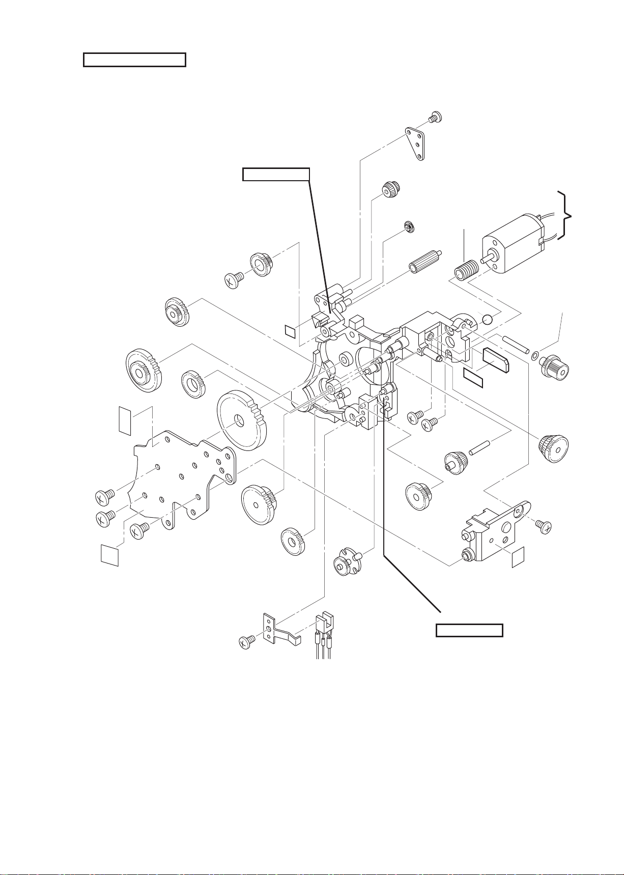
- A7 • One Touch Zoom 90s AF -
Film advance mechanism unit
● After assembling, rotate the gear [1] in right and left by hand and make sure that
each gear rotates smoothly and the planetary gear operates normally.
SSM-1609
SSS-1203
SSS-1004
SSG-1043
SSG-1025
SSG-1061
SSG-1061
SSG-1061
SSG-1241
SSG-1040
SSG-1039
SSG-1038
SSG-1075
SSG-1037
SC143N40
SC143N40×4
SC143N30×2
SC143N35
SBM-1402
(No.6900001~)
1K999-281
(No.7900001~)
SBM-1401
SSG-1002A
FCA54201
②
①
Oil:LEN315F
Apply it to each gear shaft.
FCA54001-R.3567.A
- A8 • One Touch Zoom 90s AF -
Zoom mechanism unit
● After assembling, connect the battery to the wire 1 of the motor and make sure that abnormal
noise does not occur in normal and reverse rotation.
SC143N30
SBP-8202
SBG-8013
SBG-8012
SBG-8011
SSE-9004
SSG-9201
SSL-9204
SSG-8008
SSG-8009
SSL-9205
SSG-8010
SST-9009×2
SBG-8014
SC143N30
SC143N40
SST-0008
SBM-8202
SBM-8205
SBG-8010
SSG-8011
SSG-8012
SBG-8209
SSG-8014
SBG-8005
SBG-8008
SSG-8413
SST-0008
SST-0222
SC143N40×3
SBP-8401
SSE-8002
SST-0026×2
SSP-8002
SC143N30
SBP-8005
SBT-8004
SST-8004
SSP-8003
SST-8205
①
Oil:LEN315F
Oil:LEN315F
Apply it to each gear shaft.

FCA54001-R.3567.A
- A9 • One Touch Zoom 90s AF -
Film advance mechanism unit installation
● Mount the lm advance mechanism unit 1 to the bottom of the body with the ve screws 2
and one screw 3.
Lens barrel unit installation
● Mount the lens barrel unit 1 and tighten the four screws 2.
②×5
①
*Long screw is strictly prohibited.
③×1
Wires must not be piled.
PR PCB
①
②×4

FCA54001-R.3567.A
- A10 • One Touch Zoom 90s AF -
Zoom mecahnism unit installation
● Put the zoom mechanism unit 1 into the groove of the body to mount it and tighten the two
screws 2.
Speed light unit installation
● Solder the red wire of the battery terminal and black wire of the terminal SP 2 to the speed
light PCB 1.
①
Guide the wires upward.
②×2
Put the zoom mechanism
unit into the groove.
①
②
If it is difcult to put it in,
turn the lens barrel in right and
left and t the gear.

FCA54001-R.3567.A
- A11 • One Touch Zoom 90s AF -
● Mount the speed light PCB 3 and tighten the two screws 4.
● Push the red wire of the battery terminal into the condenser house.
③
④×2
⑥
⑤
Arrange the red and black
wires of the main condenser
to the rear lower section of
the PCB.
Fix the outside of the PCB
with a screw.
Black wire of terminal SP
Push the red wire of the battery
terminal into the condenser house.

FCA54001-R.3567.A
- A12 • One Touch Zoom 90s AF -
Finder unit installation
● Mount the nder unit 1 to the body and tighten the three screws 2.
②×3
①
Turn the gear and tighten the screws
in the innermost of the hole.
Guide the red and black wires to the
right side not to trample them.

FCA54001-R.3567.A
- A13 • One Touch Zoom 90s AF -
AF unit installation
● Mount the AF unit 1 to the body and assemble the FPC retainer 2.
● Mount the AF unit 1 to the body and tighten the two screws 3.
● Solder the wires.
Refer to the wiring diagrams of page E1 and E2.
①
②
Guide the wire of PR PCB
to the left backward.
Bend the exible wires.
①
③×2

FCA54001-R.3567.A
- A14 • One Touch Zoom 90s AF -
Wire processing
Any wire must not pass above it.
Don’t pile the wires but
arrange them in a line.
TA-0013 (12×20)
Don’t put the orange wire
near the transformer.
Orange wire
TA-0013 (12×20) TA-0003 (5×8)
TA-0004 (8×8)
TA-0004 (8×8)
TA-0004 (8×8)
Don’t pile the wires but
arrange them in a line.
Any wire must not get on
the gear box.
TA-0013 (12×35)

FCA54001-R.3567.A
- A15 • One Touch Zoom 90s AF -
Finder positioning
● Set the lens barrel to the W end.
● Set the groove 1 of the gear #127 1mm leftward from the line 2 connecting the gear
#127 with #128.
● Insert the gear #117 and tighten the screw 3.
Front cover installation
①
②
③

FCA54001-R.3567.A
- A16 • One Touch Zoom 90s AF -
inspection and adjustment
● Inspection and adjustment with test mode
1. Preparation
1) Turn the objective lens of the collimator (J19019) and set the scale to –2.4mm (-24 division).
2) Set “0” for the display of the FFD adjusting micro mount (J15327).
2. Set the manual test mode for the camera.
1) Open the camera back and set the camera back switch to “camera back closed”.
2) Set the main switch to “ON” and move the lens barrel forward to the W end.
3) As keeping the speed light mode switch “ON”, set the lm rewind switch to “ON” to display
“LS” on LCD.
4) Carry out release and set to “valve”.
3. Start inspection.
1) Set a camera on the micro mount.
2) Turn the spindle of the FFD adjusting micro mount (J15327), read the value where the collimator
(J19019) is in focus and make sure that the read value is within standard.
3) Operate the zoom switch and, at each zoom position, perform inspection in the same way.
4) If the values are within standard, carry out the ending operation of Item 4. If they are out
of standard, proceed to Item 5 and carry out adjustment.
4. Ending operation
1) Operate the main switch and exit from the test mode.
2) Set the camera back switch to “open” and then close the camera back.
Zoom position Standard of adjustment
6(TELE side) -300~+300μ m
5 -300~+300μ m
4 -300~+300μ m
3 -300~+300μ m
2 -300~+300μ m
1(WIDE side) -200~+200μ m
Collimator
FFD micro adjusting mount

FCA54001-R.3567.A
- A17 • One Touch Zoom 90s AF -
5. Perform adjustment.
1) Turn the spindle of the micro mount and set to “0µm”.
2) Set the lens barrel to the T end.
3) Carry out release to set “valve” and turn the front lens group to be in focus.5 .
4) Set the lens barrel to the W end.
5) Under the bulb open condition, turn the spindle of the micro mount to be in focus.
6) Repeat 2) ~ 5) till the T end and W end are in focus.
7) Turn and shift the rear lens group by the value of the micro mount adjusted at the W end.
8) Turn the spindle of the micro mount to set to “0µm”.
9) Make sure that focus is correct at the W end under the valve open condition.
10) After adjustment, apply adhesive to the front and rear lens groups to x them.
Adhesive: 1401B
Adhesive: 1401B
1 turn of the rear lens group is equivalent
to 500µm.
Turn it counterclockwise for negative value.
Turn it clockwise for positive value.

FCA54001-R.3567.A
- A18 • One Touch Zoom 90s AF -
● Inspection and adjustment with personal computer
1. Connect a camera to a personal computer. 1.
2. Start the inspection/adjustment software.
·Select the item of back focus adjustment in the main menu.
·Carry out inspection and adjustment according to the display on the personal computer.
·The contents of inspection and adjustment are the same as “Inspection and adjustment with
test mode”.
Set the switch to “NEW”.

FCA54001-R.3567.A
- A19 • One Touch Zoom 90s AF -
AE inspection
● Inspection and adjustment with personal computer
1) Connect a camera to a personal computer.
2) Set the camera onto a shutter tester.
3) Start the inspection/adjustment software and execute AE inspection.
·Carry out inspection according to the display on the personal computer. If a value is out
of standard, replace the AF unit.
Standard: -1.0 ~ +2.0EV
AF inspection and adjustment
● Inspection and adjustment with personal computer
1) Connect a camera to a personal computer.
2) Let the camera face a standard reex paper (18%).
3) Start the inspection/adjustment software and execute AF inspection and adjustment.
·Carry out inspection and adjustment according to the display on the personal computer.
Standard:
● Inspection with test mode
·Set the manual test mode for the camera.
1) Set the main switch to “ON”.
2) As keeping the speed light mode switch “ON”, set the lm rewind switch to“ON”
and red eye/self switch to “ON” to display AF on LCD.
3) Let the camera face a standard reex paper (18%), lightly press the release button at the
Specied distance and check the step number displayed on LCD.
4) When you hope to release the test mode, set the main switch to “OFF”.
Distance (m) Step
3.0262 6~7
2.3567 8~9
1.7838 11~12
1.2802 16~17
0.9698 22~23
0.7000 29~30

FCA54001-R.3567.A
- A20 • One Touch Zoom 90s AF -
Camera back·Side cover installation
Barrier installation
● Move the lens forward, mount the barrier and tighten the two screws.

FCA54001-R.3567.A
- One Touch Zoom 90s AF -
ELECTRIC CIRCUIT
WIRING FIGURE (Normal model) ・・・・・・・・・・・・・・・・・・・・・・・・・・・・・・・・・・・・・・・・・・・・・・・・・・ E1
WIRING FIGURE (QD model) ・・・・・・・・・・・・・・・・・・・・・・・・・・・・・・・・・・・・・・・・・・・・・・・・・・・・・・ E2
WIRING FIGURE (Date module) ・・・・・・・・・・・・・・・・・・・・・・・・・・・・・・・・・・・・・・・・・・・・・・・・・・・ E3
CIRCUIT DIAGRAM (Normal model) ・・・・・・・・・・・・・・・・・・・・・・・・・・・・・・・・・・・・・・・・・・・・・・・・ E4
CIRCUIT DIAGRAM (QD model) ・・・・・・・・・・・・・・・・・・・・・・・・・・・・・・・・・・・・・・・・・・・・・・・・・・・・ E5

FCA54001-R.3567.A
- E1 • One Touch Zoom 90s AF -
STO
SDK
FDN
GND
PR PCB
半田
Soldering
中継FPC
シャツター
Shutter
Camera back SW PCB
裏蓋SW PCB
CASターミナルGx3
CAS terminal Gx3
Motor
ハウスマーク側
House mark side
赤目ランプ
Red-eye reduction lamp
リーフSW A
Leaf SW A
PI
S印側
ズームモーター
Zoom motor
ハウスマーク側
House mark side
バッテリーターミナルSP
Battery
terminal SP
バッテリーターミナルH
Battery
terminal H
SBユニット
SB unit
Red
赤
赤
Red
茶
Brown
黒
Black
Black
黒
赤
Red
White
白
OK LED
Red
赤
Yellow
黄
空色 Sky blue
緑 Green
Yellow
黄
空色 Sky blue
緑 Green
黒
Black
Black
Black
Orange
橙
White
白
灰 Gray
灰 Gray
Pink 桃
Pink 桃
Pink 桃
青 Blue
Pink 桃
青 Blue
Black
黒
赤 Red
赤 Red
赤 Red
Black
黒
Yellow
黄
Yellow
黄
Orange
橙
茶
Brown
Yellow
黄
Yellow黄緑 Green
橙 Orange
白 White
茶 Brown
緑 Green
Orange
White
実体配線図 WIRING
(NORMAL MODEL)
DX1
DX2
DX4
B.COVER
GND
FPID
FPIS
FPI
VO4
VO3
SWH
GND
V01
V02
VDD
CS0
CSI
MLP
GND
SCLK
MKR
DB
FLED
VDD
VDD
ZPI
ZPID
MACRO
MACRO
LEDMC
REWIND
MSW
SEG0
SEG1
SEG2
SEG3
SEG4
SEG5
SEG6
COMA
COMB
COMC
MODE
S3
WIDE
TELE
S2 S1
S2
ZMD
MDC
MDC
FMD
VE
GND
LAMP
LAMP
GND
KYS
-
+
Black黒

FCA54001-R.3567.A
- E2 • One Touch Zoom 90s AF -
STO
SDK
FDN
GND
PR PCB
半田
Soldering
中継FPC
シャツター
Shutter
Camera back SW PCB
裏蓋SW PCB
CASターミナルGx3
CAS terminal Gx3
Motor
ハウスマーク側
House mark side
赤目ランプ
Red-ey
e reduction lam
p
リーフSW A
Leaf SW A
PI
S印側
S mark side
ズームモーター
Zoom motor
ハウスマーク側
House mark side
デートFPC
Date FPC
バッテリーターミナルSP
Battery
terminal SP
バッテリーターミナルH
Battery
terminal H
SBユニット
SB unit
Red
赤
赤
Red
茶
Brown
黒
Black
Black
黒
赤
Red
Orange
Orange
橙
橙
Orange
White
白
OK LED
Red
赤
Yellow
黄
空色 Sky blue
緑 Green
Yellow
黄
空色 Sky blue
緑 Green
黒
Black
Black
Black
Orange
橙
White
白
灰 Gray
灰 Gray
Pink 桃
Pink 桃
Pink 桃
青 Blue
Pink 桃
青 Blue
Black
黒
Black
黒
赤 Red
赤 Red
赤 Red
Black
黒
Yellow
黄
Yellow
黄
Orange
橙
茶
Brown
Yellow
黄
Yellow黄緑 Green
橙 Orange
白 White
茶 Brown
緑 Green
Orange
White
実体配線図 WIRING
(QD MODEL)
DX1
DX2
DX4
B.COVER
GND
FPID
FPIS
FPI
VO4
VO3
SWH
GND
V01
V02
VDD
CS0
CSI
MLP
GND
SCLK
MKR
DB
FLED
VDD
VDD
ZPI
ZPID
MACRO
MACRO
LEDMC
REWIND
MSW
SEG0
SEG1
SEG2
SEG3
SEG4
SEG5
SEG6
COMA
COMB
COMC
MODE
S3
WIDE
TELE
S2 S1
S2
ZMD
MDC
MDC
FMD
VE
GND
LAMP
LAMP
GND
KYS
-
+

FCA54001-R.3567.A
- E3 • One Touch Zoom 90s AF -
ショートパターン半田
Short pattrn soldering
デートモジュール
Date module
デートターミナル
Date terminal
デートターミナルK
Date terminal K
デートターミナルL
Date terminal L
白 White
白 White
黄 Yellow
黄 Yellow
黒 Black
黒
Black
実体配線図 WIRING
GND
X
VE

FCA54001-R.3567.A
- E4 • One Touch Zoom 90s AF -

FCA54001-R.3567.A
- E5 • One Touch Zoom 90s AF -

FCA54001-R.3567.A
- One Touch Zoom 90s AF -
INSPECTION STANDARD AND TOOLS
〔1〕Inspection standard ・・・・・・・・・・・・・・・・・・・・・・・・・・・・・・・・・・・・・・・・・・・・・・・・・・・・ R1
〔2〕Tools ・・・・・・・・・・・・・・・・・・・・・・・・・・・・・・・・・・・・・・・・・・・・・・・・・・・・・・・・・・・・・・・・・・ T1

FCA54001-R.3567.A
- R1 • One Touch Zoom 90s AF -
[1] Standard of inspection
Item Standard of judgment Method and tools
Photography
function
Photography lens
·Focal length W: f=39.60mm±5%
T: f=86.80mm±5%
Check the above under the valve condition.
Photography resolution
Fixed point photography
equivalent to 40f
·W Center: 25.0 dots/mm or more
Periphery: 12.00 dots/mm or more
Brightness of chart surface: LV9
Speed light mode: Flash prohibition
Photography distance
From the front of lens barrel at W: 1.56m
(1.62m from lm surface)
·M3 Center: 25.00 dots/mm or more
Periphery: 11.00 dots/mm or more
From the front of lens barrel at M3: 2.76m
(2.84m from lm surface)
·T Center: 25.0 dots/mm or more
Periphery: 10.2 dots/mm or more
From the front of lens barrel at T: 3.17m
(3.26m from lm surface)
(0.35d: Image surface 15.1mm/5 ring belts)
JC II chart
(4mm pitch)
Neopan SS
Microscope
Full aperture FNo ·W full apertur Fno.=4.97±5%
·T full aperture Fno.=10.90±5%
Obtain the full aperture Fno. by the actual
measured focal length.
Projector
Actual photography
performance
·There must be no harmful shading on a
picture.
Internal reection, ghost and are must
not hinder practical use.
Check by actual photography print.
Fuji SG-100
Pheripheral light
intensity
·Pheriphey light intensity must not be
extremely decreased.
15% or more at 0.5d
Check by actual sky photography.
Fuji SG-100
Color repeatability
·Color repeatability must be good.
Check by actual photography print.
Fuji SG-100
Distortion
·Distrotion must not be noticeable.
Take a picture of a linear object at W/T.
Fuji SG-100
CCI ·CCI must be within the ISO recommended
value.
Perform measurement at TELE.
Spectral
photometer
Eccentric dimness ·Eccentric dimness must not be noticeable.
Check by actual photography print.
Fuji SG-100

FCA54001-R.3567.A
- R2 • One Touch Zoom 90s AF -
Item Standard of judgment Method and tools
AF
performance
AF focusing function
·W/M/T
There must be 33 frames or more and each
of them must be 20.0 dots/mm or more.
There must be 3 frames or more and each
of them must be 8.0 dots/mm or less.
Distance from the inner rail surface to the
object
0.8 ~ 3.5m:
You must take a picture every 10cm.
3.8m/4.0 ~ 7.0m:
You must take a picture every 50cm till
total 36 pictures are taken.
Brightness of chart surface: LV9
Speed light mode: Flash prohibition
Neopan SS
Oxford gray
No.22
Wavelength: 880nm
Reectance: 35±5%
Powersupply (1)
Innity photography
·There must be no extreme defocus.
15 dots/mm or more in AF innitiy
20 dots/mm or more in forced innity
Take a picture of distant view in the forced
innity mode and AUTO.
In T/M/W, when the external light has the
same brightness as the speed light
luminance, cover the camera metering
unit, set aperture to “full” and take a
picture.
Fuji SG-100
Beam irradiation
position
·The center of AF beam must be within the
specied chart range.
Let the camera face the specied chart
from 1m distance and press the release
button lightly.
Infrared rays
camera/Monitor
Target mark
Sheet Camera
Fixing jig and
tool
AF distance
measurement accuracy
·There must be no step deviation.
(±1 step in Bv ≦ 7)
Check the distance measurement length
and AF step in a special mode.
AF no-signal control
·The camera must be positioned at AF
innity.
Shield the light emitting unit, let the light
source “A” face the light receiving unit and
check at Bv ≦ 7.
Lens barrel
unit
Lens barrel operation
·The lens barrel must not operate by self-weight
at each position.Set the zoom at each step, grasp
and lift the lens barrel.Set the zoom at each
step and put the camera on a ground with its lens
barrel at the bottom.
·The lens barrel must move forward properly.
Measure the forward moving quantity of the lens
barrel at each step.
Visual check
Lens cover
·The lens cover must be opened and closed
smoothly.
It must not be caught halfway.
Press the main switch button, move the lens
barrel from the push-in position to the W end
position and then return it to the push-in position.
Visual check
Play of lens barrel
·Twist thrust must be 0.3mm or less.
Twist the end of lens barrel at T end.
·The end apping must be 0.5mm or less.
Add the apping load, 100gf.
Special gauge

FCA54001-R.3567.A
- R3 • One Touch Zoom 90s AF -
Item Standard of judgment Method and tools
Lens barrel
unit
Eccentricity
·The clearance between the lens barrel and front
cover must be 1/2 or less of the difference
between the maximum and minimum parts.
Check the clearance between the lens barrel and
front cover.
Pin gauge
Driving noise
·It must be 58dB or less at average sound
pressure.Abnormal noise must not occur during
operation.Measure noise in 45° at a position
20cm away from the lens front surface.
Lens barrel abnormal
stop
·There must be 400g or more in the upward
position.Set the lens barrel upward and put a
special gauge on it.
Special gauge
Automatic
exposure
AE accuracy
AE tester
Power supply(1)
·The camera must meet the following
conditions in ISO100, 200, 400 and 800.
·Unexposed photography must not occur.
Application range A
WIDE: 6 ≦ Ev ≦ 15.0
TELE: 6 ≦ Ev ≦ 17.0
Error: +2.0 ~ -1.0Ev
Difference: 1.5Ev
Neighboring difference: Reverse must not occur
every 1.5Ev.
Application range B
WIDE: 15.0<Ev ≦ 16.0
TELE: 17.0<Ev ≦ 18.0
Error: +2.5 ~ -1.5Ev
Difference: 2.0Ev
Neighboring difference: Reverse must not occur
every 2.0Ev.
Error: Error of each measured value obtained by
continuous 3 measuring operations
Difference: Difference between the maximum and
minimum values obtained by continuous 3 measuring operations
Neighboring difference: Average value obtained
by measuring the neighboring exposure values 3
times continuously
FM accuracy
Application range A: 4.94 ≦ F ≦ 11.31
Error: +2.0 ~ -1.0Av
Difference: 1.5Av
Neighboring difference: Reverse must not occur
every 1.5Av.
Application range B: 11.31 ≦ F ≦ 16.00
Error: +2.3 ~ -1.3Av
Difference: 1.8Av
Neighboring difference: Reverse must not occur
every 1.8Av.
AE tester
Power supply(1)
Speed light Guide number
·Gno.: 10 (ISO100·m)±0.5Ev
·Point and line: Gno.7.1 or more
Measure the guide number at a position
1.97m away from the speed light whole
surface. (From lm surface: 2m)
JC II ash
Meter IV
Power supply(1)
Light division
characteristics
·At 28° in the right and left direction
and 20° in the up and down direction,
within -1Ev against the image center
JC II ash
Meter IV
Power supply(1)
Recycling time ·8 seconds or less
Release occurs after 8 seconds since winding
ended.
Power supply(1)
Stop watch

FCA54001-R.3567.A
- R4 • One Touch Zoom 90s AF -
Item Standard of judgment Method and tools
Speed light
Automatic ash change
accuracy
W: Bv 5.625±1Ev
T: Bv 8.875±1Ev
AE tester
Color temperature
·5800°K±300
Measure the temperature at point and line ash.
Minolta color
Meter Ⅲ F
Red eye reduction
accuracy
·Brightness should be approx. 10 LUX or more.
Measure the brightness at a position 30cm away
from the camera front nder cover in a dark
room.
Minolta digital
illuminometer T-1
Film advance
Film scratch ·The photographed picture must not have harmful
scratch.
Take pictures with two lms and observe the pictures from beginning to end.
Fuji Neopan SS
Power supply(1)
Film damage
·Film must not have damage which affects
adversely the lm advance and the photographed
picture.Check negative lm for damage.
Fuji Neopan SS
Power supply(1)
Space between pictures
·Within 0.5 ~ 3.5mm in the speci ed picture
number
·The specied number of pictures must be taken.
Overlap of the last frame (out of the specied
number) is allowable.
Check the space between pictures with the negative lm which has been used to the last frame
at 36EX.
Take pictures by 18 shots at T/W in the forced
innity mode.
Fuji Neopan SS
Power supply(1)
And (3)
Visual check
Picture size
・24
+0. 8 –0.3
mm×36
+0. 8 –0.3
mm
Check the picture size with negative lm.
Take pictures at W/T in the forced innity
mode.
Fuji Neopan SS
Vernier calipers
Picture position
·Up and down direction: 0.2mm or more between
the picture and perforation There must be no
extreme inclination.Check the picture position
with the negative lm which has been used in
T/W photography.After one frame of picture has
been photographed, add vibration of reliability, take a picture again and check its position.
Fuji Neopan SS
Power supply(1)
And (3)
QD copy center position ·X=11.5mm Y=-9mm
When all the digits are copied, the bottom of
characters must be 2.7±0.5 from the outline of
the negative lm and their right side must be
4.5±0.5.
Check the position with the negative lm which
has been used at W end and M/T from the front of
lens barrel.
Fuji Neopan SS
Inspection jig and
tool
Time of each operation
·One frame advance: Within 1 second
Measure the time after release.
·36EX rewinding: Within 40 seconds
Start measurement the moment the last frame is
released.
Fuji ISO100
Power supply(1)
Stop watch

FCA54001-R.3567.A
- R5 • One Touch Zoom 90s AF -
Finder Finder
·The eld of viewnder must be 80% or
more and less than 100% against the
picture image in vertical and horizontal
directions.
Check the eld of view nder with the negative
lm which has been used at W end 2.94m and T
end 2.91m (W/T 3m from lm surface).
·The visual eld must not be inclined
extremely.
·Parallax: It must be within the picture
to be taken.
·In near distance photography, the whole
visual eld must be taken at the top,
right and left.
The bottom must not be protruded extremely.
At T 0.61m (0.7m from F surface) and macro 0.24m
(0.7m from F surface), take a picture according
to the “d” near distance compensation frame.
Fuji Neopan SS
Item Standard of judgment Method and tools
·Diopter: -0.7 diopter +0.5/-1
Measure T/W in a distant view of 30m or more
with a diopter telescope.
·Diopter difference between image and frame:
0.7 diopter
Diopter difference of T/W: Within 1.0 diopter
Perform measurement with WIDE as standard.
·Magnication
W 0.336±15% T: 0.686±15%
By using a diopter telescope, measure the distance between two points of 50m or more away
from each other when a camera is used and when
a camera is not used.
·The AF beam center position must be within the
target mark.
In a 3m distance, check the misalignment for
the AF zone and AF beam center of the nder.
·There must be no optical axis misalignment.
In a 3m distance, mark the center of the target
mark at WIDE. At TELE, the center of this mark
must not deviate from the target mark.
Diopter telescope
Visual check
Electric
current
consumption
SI ON condition
60mA or less
Measure the electric current when OK LED
lights after BC.
Ammeter/Power
supply (1)
Use the power
supply (2)
to measure the
operating time.
AE series
380mA or less
Measure the electric current at luminance without speed light ash.
Self-timer operation
150mA or less
Measure the electric current when self-timer is
operating.
Film winding 420mA or less
Measure the electric current when one frame is
being advanced during FFS.
Film rewinding
460mA or less
Measure the electric current when lm is being
rewound.
Auto. power OFF 10µA or less
Measure the electric current under the auto.
power OFF condition.
Main switch ON
10µA or less (40mA or less at the last stage of
speed light pressurization)
Measure the electric current after 1 minute
since the main switch was turned on.

FCA54001-R.3567.A
- R6 • One Touch Zoom 90s AF -
Item Standard of judgment Method and tools
Electric
current
consumption
Ammeter/Power
supply (1)
Use the power
supply (2)
to measure the
operating time.
Zoom Zo → W
500mA or less/operating time: 1 second or less
Measure the electric current as pressing the
zoom button.
TYP of electric current consumption is approx.
300mA.
Zoom W → T
500mA or less/operating time: 3 seconds or less
Zoom T → W
500mA or less/operating time: 3 seconds or less
Zoom W → Zo
500mA or less/operating time: 1 second or less
BC voltage
BC warning voltage
Power supply(3)
Visual check
·At 2.45 ~ 2.70V, the battery mark must
blink and release must be possible.
Other displayed items must be normal except the
battery mark.
·At 2.40±0.1V, the battery mark must
blink and release must be possible.
This voltage value is standard in a camera and
actual measurement is not possible.
After checking the battery mark on LCD, perform
release.
BC lock voltage
Power supply(3)
Visual check
·At 2.25 ~ 2.50V, the battery mark must
blink and release must be impossible.
Others must be turned off except the battery
mark.
·At 2.20±0.1V, the battery mark must
blink and release must be impossible.
This voltage value is standard in a camera and
actual measurement is not possible.
·The BC warning voltage and BC lock voltge
must not be reversed in a same camera. (Electric potential difference: 0.1V or more)
·At 2.10±0.1V, LCD is turned off.
After checking the battery mark on LCD, perform
release.
Battery life
Film advance quantity ISO100 24EX
Power supply(2)
·Normal temperature: When a lm of 24
frames is used, you can take pictures of
15 lms or more (on the condition that
speed light 50% is used).
·-5°C: When a lm of 24 frames is used,
you can take pictures of 3 lms or more
(on the condition that speed light 50% is
used).
Perform 13 shots of speed light ash at intervals of 8 seconds and perform release continuously in the ash prohibition mode till
automatic return occurs.
Carry out zoom operation once every shot.
After rewinding is ended, load the next lm cartridge at once.

FCA54001-R.3567.A
- T1 • One Touch Zoom 90s AF -
[2]TOOLS
1.Major general tools and testers ☆:New tool
Tool No. Name Specications
J19019 Collimator 24LT-2DTS
f=193.5mm
J15291 Micro stand for adjusting FFD
J19036 Multi shutter tester EF511N, EF-8000
J19042
J18190 Standard reect paper OXFORD GRAY N0.22
J15312 Connection tool
J15325 Interface box for LS CAMERA
☆ J18337 Adjustment software IBM 3.5 inch
 Loading...