

Nikon Eclipse TI-TIRF-E, Eclipse TI-PAU, Eclipse TI-TIRF, Eclipse Ti, LU4-B5 Setup Manual
...
M456 E 10.9.NF.5
*M456EN05*
Series
TI-TIRF Illuminator Unit
TI-TIRF-E Motorized Illuminator Unit
TI-PAU Photo Activation Illuminator Unit
TI-TIRF-PAU Illuminator
LU4-B5 Beamsplitter 50/50
Setup Manual
<For Authorized Nikon Personnel>
WARNING
This manual is intended to provide setup instructions for Nikon
representatives who have attended the lecture on laser safety and have been
trained in setup operations. Attempts by others to set up the product may
lead to accidents or equipment failure. NIKON is not responsible for personal
injury or equipment damage resulting from equipment setup performed by
unqualified persons.
Be sure to observe the warnings and cautions described in this manual to
ensure safety during setup.


Introduction
This setup manual is written for service personnel who is installing the Nikon TIRF Illuminator Unit,
Motorized TIRF Illuminator Unit, Photo Activation Illuminator Unit, TIRF-PAU Illuminator, and Beamsplitter
50/50 for Ti Series Inverted Microscopes.
To ensure correct installation, read this manual carefully before installing the product.
• No part of this manual may be reproduced or transmitted in any form without prior written permission from
Nikon.
• The contents of this manual are subject to change without notice.
• This manual contains confidential information. Do not disclose this manual to a third party other than the
authorized Nikon personnel.
• Although every effort has been made to ensure the accuracy of this manual, errors or inconsistencies may
remain. If you note any points that are unclear or incorrect, please contact a Nikon Service Department.
• Some of the equipment described in this manual may not be included in the set you are installing.
• If you intend to use any other equipment with this product, read the manual for that equipment too.
• If the equipment is used in a manner not specified by the manufacturer, the protection provided by the
equipment may be impaired.
1
Safety Precautions
To ensure correct and safe operation, read this manual before using the product.
WARNING and CAUTION Symbols Used in This Manual
Although this product is designed and manufactured to be completely safe during use, incorrect usage or
failure to follow the safety instructions provided may cause personal injury or property damage. To ensure
correct installation, read the setup manual carefully and thoroughly before installing the product.
Safety instructions in this manual are marked with the following symbols to highlight their importance. For
your safety, always follow the instructions marked with these symbols.
Symbol Description
WARNING
CAUTION
All procedures should be performed safely and in accordance with the
instructions in this manual to prevent accidents or equipment failures.
Disregarding instructions marked with this symbol may lead to serious injury
or death.
Disregarding instructions marked with this symbol may lead to injury or
property damage.
2
Safety Precautions
Meaning of the Symbols Used on the Product
The symbols marked on the product indicate the need for caution at all times during use.
Always refer to the instruction manual and read the relevant instructions before manipulating any part
to which the symbol is marked.
Symbol Meaning
Warning label - laser hazard symbol
This symbol is displayed on the laser safety cover or on the stage to warn that the product
emits laser light.
Your eyes or skin may be exposed to the laser light emitted from the objective, resulting in
injury.
Precautions against heat
This symbol, affixed to the top of the dia pillar illuminator, the rear side of the 12V-100W
lamp house, the HG fiber light source, and the rear side of the super-high pressure
mercury lamp (or the xenon lamp) house, calls your attention.
• The lamp and the lamphouse become hot while the lamp is lit and immediately after it
is turned off.
• Do not touch the lamp and the lamphouse while the lamp is on and immediately after it
is turned off to prevent the risk of burns.
• Make sure that the lamp and the lamphouse are sufficiently cool before the lamp
replacement.
Biohazard
This symbol on the upper part of the microscope calls your attention on the following:
• If a specimen is spilled onto the product, it may cause the danger of biohazard.
• To avoid biohazard contamination, do not touch the contaminated portion with your
bare hands.
• Decontaminate the contaminated portion according to the standard procedure of your
facility.
General attention
This symbol is displayed on the top of the protection plate (for nosepiece) appended to the
Ti-E and Ti-E/B and the protection plate (for PFS6 nosepiece) appended to the TI-ND6-PFS
motorized PFS6 nosepiece. It calls your attention on the following:
• To avoid accidents such as finger pinching and exposure to laser radiation, install this
product in the correct position.
3
Safety Precautions
WARNING
Use of controls or adjustments or performance of procedures other than those specified in this manual
may result in hazardous radiation exposure.
1. Laser class
This product is a laser apparatus that uses Class 3B lasers (air-cooled Ar lasers, He-Ne lasers,
semiconductor lasers). Accidental exposure of eyes or skin to laser light may result in injury or
other problems. Confirm that there is no one in the area before turning on the lasers. Always wear
laser-protection goggles when using the laser.
2. Laser safety
This product is designed and manufactured in compliance with the Performance Standards for
Light-Emitting Products established by the U.S. FDA and the IEC Laser Product Safety Standard
(IEC 60825-1), except for deviations pursuant to Laser Notice No.50. Those using this laser
product must complete laser safety courses and setup training. Users are requested to take all
appropriate safety measures specified by the preceding standards, in accordance with local laws
and regulations.
The laser safety officer (LSO) must take charge of this laser product and users should follow the
instructions from the LSO.
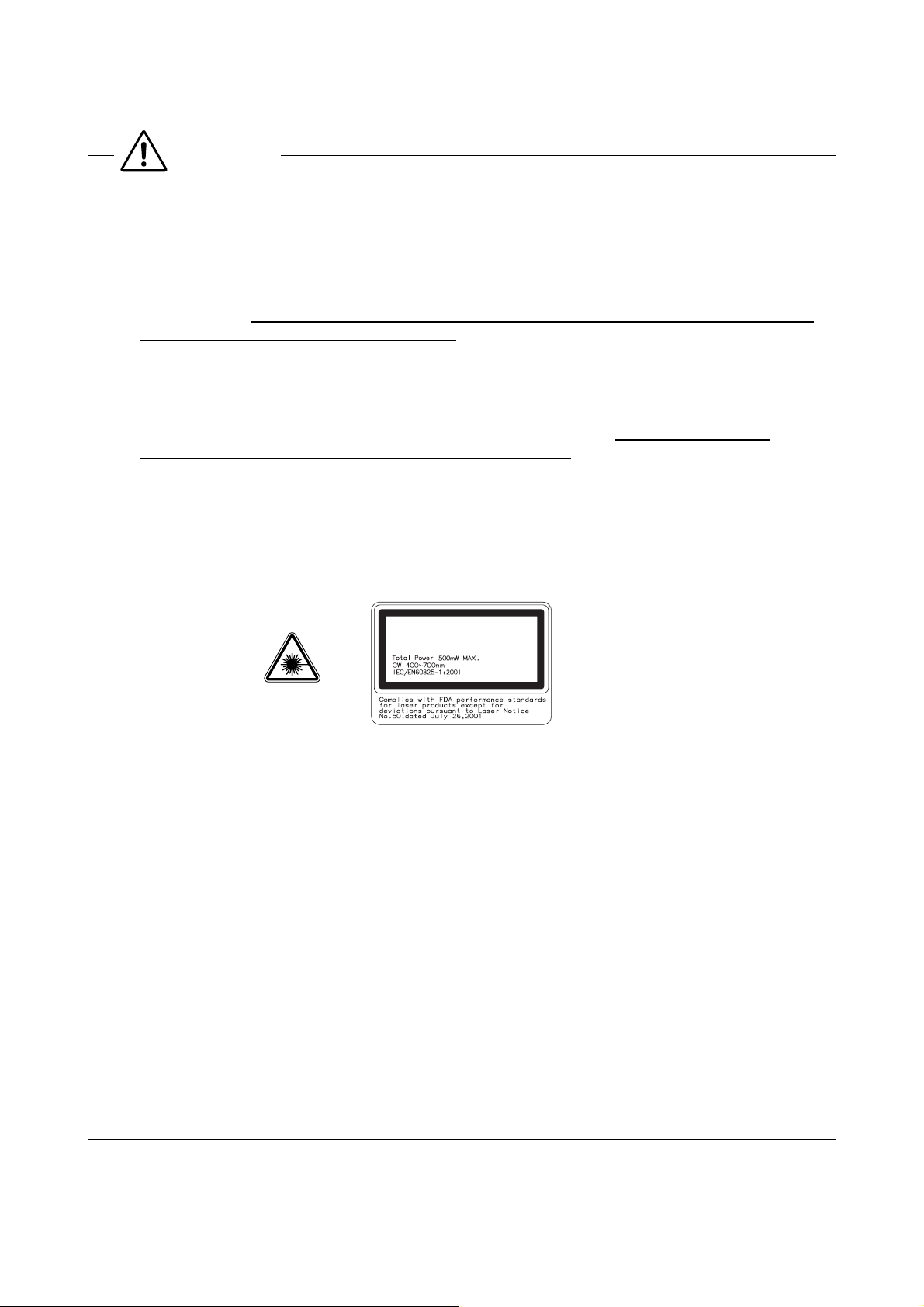
FDA Class 3B Laser Product (Laser Notice No. 50)
IEC Class 3B Laser Product
LASER RADIATION
AVOID EXPOSURE TO BEAM
CLASS 3B LASER PRODUCT
Wavelength: 400 to 700 nm (CW)
Beam divergence: 0.01 to 2.91 rad
Maximum power or energy output: total power 500 mW Max. (CW)
3. Manuals and accessories
All manuals and accessories used in this laser product and provided by the distributor must be
provided to the user.
4. Intended application of the product
This product can be used only for microscopic observations. This product is required to be
attached to the specific Nikon microscope, Ti-E, Ti-E/B, Ti-U, Ti-U/B. Do not use this product for
other purpose.
5. Setting up the product
Setup of this product must be handled by trained service personnel.
This task should not be performed by anyone other than the trained service personnel. If
performed, it may result in improper setup, impairing system performance and exposing the eyes
or skin to the laser light, resulting in injury.
4

Safety Precautions
WARNING
6. Prohibition of dismount
This product uses a laser device. Use only in the configuration set up by the Nikon representative.
To ensure safety, never attempt to remove any part of the system. Before beginning operations,
confirm that all of the parts listed below are in place. Removal of any following part during use may
result in unintended exposure of eyes or skin to laser light.
Make sure that all powers to the laser and entire system are turned off when removing an objective
or a filter cube.
Eyepiece tube, nosepiece, objective, TIRF/motorized TIRF illuminator unit, photo activation
illuminator Unit, TIRF-PAU illuminator, filter cube, sage, lamp house, HG fiber adapter,
epi-fl filter turret, 3D-STORM port, TV camera, video camera, or all port caps
7. Do not disassemble.
Disassembling this product may result in electric shock or other hazards.
Never attempt to disassemble any piece of equipment included in this product.
In particular, disassembling any of the components when the laser is on may cause the laser light
to be improperly emitted from this product. If you notice that this product is not functioning properly,
immediately stop use, switch off the power switches to all devices, disconnect the power cables
from the outlets, and contact your nearest Nikon representative.
8. Pre-operation check items
Before using the system, always confirm the followings.
If the following conditions are not satisfied, laser light may be irradiated from openings or reflected
from reflective objects, and unintended exposure of eyes and skin to laser light may result.
1 A cap, 3D-STORM port, a TV camera, or a video camera is attached to each port.
2 An objective or a cap is attached to each socket of the nosepiece.
3 The optical fiber for laser light is securely fixed.
4 The adapter for the HG fiber light source (or the lamphouse) is attached for epi illumination.
And the lamphouse is attached for the dia illumination.
5 The epi-fl filter turret is attached correctly. (Its cover is attached too.)
6 The field diaphragm unit is attached correctly.
7 The laser safety cover is attached on the stage. (The specimen cover is attached for TI-PAU.)
8 There is no mirror or other highly reflective piece of metal in the area surrounding the lens
aperture.
9. Never attempt to look into the laser light.
When the laser is on, a powerful beam of light is emitted above the stage through the objective.
Never look into this beam or reflected beams. When the laser is on, put on laser safety goggles.
To prevent reflection of the laser light emitted from the objectives and resulting inadvertent
exposure of eyes or skin to laser light, never place reflective objects on the stage or in the
diascopic optical path.
TIRF PA TIRF-PA
• NOHD: 2502 m 8.9 m 1904 m for 1x objective.
• NOHD: 642 m 2.2 m 492 m for 4x objective.
• NOHD: 258 m 0.9 m 198 m for 10x objective.
MPE at the cornea for exposure to laser radiation: 1 W/m
MPE of the skin to laser radiation: 2000 W/m
2
(400 nm to 700 nm CW)
2
(400 nm to 700 nm CW)
5

Safety Precautions
10. Cautions about heat from the light source
The
Also, the
Follow the cautions below to prevent burn injury and fire.
11. Mercury lamp and xenon lamp
The mercury lamp (or the xenon lamp) used with this product requires special handling. To use the
The hazards described above should not pose any danger as long as you heed all of the warnings
WARNING
symbols affixed to the top of the dia pillar illuminator, the rear side of the lamp house, and
the HG fiber light source indicate that the relevant lamp and its surrounding area become very hot
while the lamp is lit or right after the lamp is turned off.
symbol affixed above the air vent of the HG fiber light source indicates that hot air
blows out of the air vent while the lamp is lit.
• Never touch the lamp, its surrounding parts, and the air vents while the lamp is lit or within
30 minutes after the lamp is turned off.
• Keep hands away from the air vents when the lamp is lit. Do not block the airflow from the air
vents.
• Make sure that the lamp and its surroundings are sufficiently cool before the lamp replacement.
• Do not allow walls, curtains, or papers to contact the product.
• Do not allow cloths, papers, or highly flammable volatile materials, such as gasoline, benzine,
thinner or alcohol, to come near the lamp, its surrounding parts, or the air vents while the lamp is
lit or within 30 minutes after the lamp is turned off.
• Do not draw any power cord on the product body.
system safely and correctly, read the warnings below and be aware of potential dangers. Also,
carefully read the manuals of the light source (HG fiber light source, super-high pressure mercury
lamp power supply, and high-intensity light source) to be used and the manuals published by the
lamp manufacturer if provided, and follow their instructions.
1 The mercury lamp (or the xenon lamp) radiates ultraviolet light that is harmful to the eyes and
skin when the lamp is turned on. Direct viewing of light from these lamps may result in
blindness.
2 Gas is sealed under very high pressure inside the lamps. The pressure increases when the
lamp is on. If the lamp is scratched, dirty, subjected to high external pressure or physical
impact, or used beyond its operational life, the sealed gas may escape or the lamp may burst.
This can result in someone inhaling the gas, injuring themselves on the glass, or other
accidents.
3 When the lamp is on, the lamp and its surroundings become extremely hot. Touching the
lamp with bare hands could result in burns. Flammable materials placed near the lamp could
ignite.
4 Using other than the specified type of lamp could result in an accident, such as a burst.
and cautions in the manuals and use the system only for its intended purpose because safety is a
top priority in the design of Nikon products. However, the hazards described above could lead to
an accident if you fail to heed all of the warnings and cautions in the manuals, if you strike the
system, or if you attempt to disassemble the system. Therefore, always be sure to heed all of the
warnings and cautions.
12. Use the ultraviolet light shield
Do not directly see the light irradiated from the objective. Harmful excitation light will be given out
from the objective depending on the excitation method used. When you see the part around the
objective, be sure to see through the ultraviolet light shield.
6

Safety Precautions
13. Notes on handling flammable solvent
The following flammable solvents are used with the product:
Never hold a flame near these solvents. To use solvent, read the instructions provided by the
WARNING
• Immersion oil (Nikon Immersion Oil for oil immersion objectives)
• Absolute alcohol (ethyl alcohol or methyl alcohol for cleaning optical parts)
• Petroleum benzine (for wiping the immersion oil)
• Medical alcohol (for disinfecting the microscopy)
manufacturer and handle the solvent correctly and safely. Note the following precautions to use a
solvent with the product.
• Keep solvent from the heat of the lamp, the lamphouse, and the power supply device.
• Do not bring solvent near the product or its surroundings when turning on/off the power switch or
plugging/unplugging the power cord.
• Be careful not to spill solvent.
7

Safety Precautions
1. Precautions on power supply ratings and power cords
Before connecting the power cords to wall outlets, check your power-line ratings to make sure that
2. Precautions on connecting cables
Always switch off the power switches to all devices before connecting or disconnecting cables.
3. Emergency stop
In an emergency, turn off all power switches and unplug the power cords.
4. Do not wet the product.
Do not wet nor spill a liquid on the product to avoid malfunction, over-heating, or electric shock. If a
5. Do not place any object on the product.
To prevent deformation, failure, or malfunction, and to avoid injury, never place any objects (heavy
CAUTION
the input voltage and current capacity requirements of the products are sufficient. Using a wrong
power cord may result in malfunction, failure, or fire. Always use power cords that satisfy local
safety regulations. Always use three-pole grounded outlets.
To prevent wires from breaking, do not pull cables by the sheath; instead, firmly grasp the plug
when connecting or disconnecting a cable.
device is subject to contact with water, immediately switch off the power switch to that device and
wipe off the water with a dry cloth. If water enters a device, immediately suspend use of the
product, unplug the power cord from the outlet, and contact your nearest Nikon representative.
ones in particular) on any part of the system.
8

Safety Precautions
6. Notes on Handling the Product
CAUTION
1. Handle the product carefully.
The product is a precision optical instrument. Handle the product with care to avoid a physical
shock or an impact. Optical-fiber cables, in particular, must not be bent or pulled with
excessive force, to prevent failure, malfunction, or wires from breaking.
2. Notes on handling optical parts
Scratches or dirt such as fingerprints on an optical component (such as a lenses or a filter)
will degrade microscope images. Carefully use the optical parts. Do not damage them. If any
part becomes dirty, clean it according to the manuals for respective units.
3. Installation location
To ensure safe and reliable operations, check the following conditions when installing this
product:
• To prevent the product from falling and to avoid eventual failure, install each component of
the product on a level surface.
• Install the product in a clean place with little dust and dirt. Dust or dirt degrades system
performance significantly.
• Use this product at ambient temperatures of between +5 and +35°C and in conditions of
humidity of 60% or less (no condensation). Using the product in hot or humid conditions
may result in condensation or malfunction.
• Make sure that the product is not subject to strong vibrations, which may degrade image
quality. Consult with Nikon representatives about preventive measures you may take when
the product is installed.
• To prevent degradation, malfunction, or failure of the laser and the PC, always use power
supply that is free from electric noise or sudden voltage fluctuations.
• To prevent failure, do not block or place any obstacles near the cooling fans of the
controller and the laser. When the product is installed near a wall, be sure to provide a
clearance of 15 cm or more between the wall and the product.
• Install the product at a place where all the power cables can be pulled out easily in an
emergency.
4. Cleaning
Use a dry and soft cloth to clean painted, plastic, and printed parts. If necessary, wipe these
parts with a cloth moistened with diluted neutral detergent, then wipe off the moisture with a
soft and dry cloth. To prevent discoloration or deformation of painted or plastic parts or
removal of the printed letters/figures, do not use organic solvents such as paint thinner or
alcohol.
5. Other categories
Be sure to follow the instructions specified in this manual. Failure to do so may result in
impaired performance, malfunction, failure, or unexpected hazards.
9

How to Use This Manual
Configuration of This Manual
This setup manual is made up of two parts. Refer to the part which deals with the product you are setting up.
• Part 1 For Setting Up TI-TIRF, TI-TIRF-E, or TI-PAU
• Part 2 For Setting Up TI-TIRF-PAU and LU4-B5
10

Part 1
For Setting Up TI-TIRF, TI-TIRF-E, or TI-PAU
Series
Setup Manual
<For Authorized Nikon Personnel>


Contents
1. System Configurations and Part Names............................................................................................1-4
1.1 Overview ........................................................................................................................................ 1-4
1.1.1 TIRF Illuminator Unit and Ti-U System Overview .............................................................. 1-4
1.1.2 Motorized TIRF Illuminator Unit and Ti-E System Overview ............................................. 1-8
1.1.3 Motorized TIRF Illuminator Unit, LU4A, N-STORM, and Ti-E System Overview............. 1-12
1.1.4 TI-PAU Photo Activation Illuminator Unit and Ti-U System Overview.............................. 1-14
1.2 Optical Paths of Lasers ................................................................................................................ 1-18
1.2.1 Laser Unit......................................................................................................................... 1-18
1.2.2 Microscope Part (TIRF Illuminator Unit and Ti-U System)............................................... 1-19
1.2.3 Microscope Part (Motorized TIRF Illuminator Unit and Ti-E System) .............................. 1-20
1.2.4 Microscope Part (Motorized TIRF Illuminator Unit, LU4A, N-STORM, and Ti-E System)1-21
1.2.5 Microscope Part (Photo Activation Illuminator Unit and Ti-U System)............................. 1-22
1.3 Safety Labels and Openings ........................................................................................................ 1-23
1.3.1 Ti-U Microscope Body (with the TIRF Illuminator Unit).................................................... 1-24
1.3.2 Ti-E Microscope Body (with the Motorized TIRF Illuminator Unit)................................... 1-25
1.3.3 Ti-U Microscope Body (with the TI-PAU Photo Activation Illuminator Unit)........................ 1-26
1.3.4 C-LU2 Two-laser Unit....................................................................................................... 1-27
1.3.5 C-LU3 Three-laser Unit.................................................................................................... 1-28
1.3.6 C-LU3EX Three-laser Unit EX ......................................................................................... 1-29
1.3.7 LU4A Four-laser Module A............................................................................................... 1-30
1.3.8 LU-LR Four-laser PS Rack .............................................................................................. 1-31
1.3.9 TI-LUSU Shutter Unit....................................................................................................... 1-32
1.3.10 TI-LU4SU Shutter Unit LU4 ............................................................................................. 1-34
1.3.11 TI-TIRF TIRF Illuminator Unit........................................................................................... 1-36
1.3.12 TI-TIRF-E Motorized TIRF Illuminator Unit ― For Normal Microscopy
(Except N-STORM).......................................................................................................... 1-37
1.3.13 TI-TIRF-E Motorized TIRF Illuminator Unit ― For N-STORM Microscopy...................... 1-38
1.3.14 TI-PAU Photo Activation Illuminator Unit ......................................................................... 1-39
1.4 Name of Each Part....................................................................................................................... 1-40
1.4.1 TIRF Illuminator Unit and Ti-U System ............................................................................ 1-40
1.4.2 Motorized TIRF Illuminator Unit and Ti-E System............................................................ 1-45
1.4.3 Motorized TIRF Illuminator Unit, LU4A, N-STORM and Ti-E System.............................. 1-49
1.4.4 TI-PAU Photo Activation Illuminator Unit and Ti-U System.............................................. 1-54
1.4.5 Laser Unit......................................................................................................................... 1-58
1.4.6 Laser Safety Kit................................................................................................................1-62
1.4.7 Related Product ............................................................................................................... 1-64
2. Preparations........................................................................................................................................ 1-67
2.1 Check Items and Tools ................................................................................................................. 1-67
2.1.1 Required Items................................................................................................................. 1-67
2.1.2 Tools ................................................................................................................................. 1-68
2.2 Overview of Setup Procedure ...................................................................................................... 1-69
3. Setting Up the PC and Operation Software ..................................................................................... 1-70
1-1

Contents
4. Setting Up the Microscope ................................................................................................................ 1-71
4.1 List of Parts .................................................................................................................................. 1-71
4.2 Setup Procedure .......................................................................................................................... 1-74
4.2.1 Assembling Each Part and Attaching Them to the Microscope....................................... 1-74
4.2.2 Attaching the N-STORM Kit............................................................................................. 1-85
4.2.3 Attaching the Laser Safety Kit.......................................................................................... 1-87
4.2.4 Attaching the Stage Up Kit............................................................................................... 1-89
4.2.5 Attaching the Back Port Unit............................................................................................ 1-92
5. Laser Unit............................................................................................................................................ 1-93
5.1 Overview of the Laser Units......................................................................................................... 1-94
5.1.1 AOM Controller (Optional) ............................................................................................. 1-100
5.1.2 LU-LR Four-laser PS Rack ............................................................................................ 1-101
5.2 C-LU2 Two-laser Unit, and C-LU3 Three-laser Unit .................................................................. 1-103
5.2.1 Preparation.....................................................................................................................1-103
5.2.2 Laser Installation............................................................................................................ 1-104
5.2.3 Laser Rough Adjustment................................................................................................ 1-106
5.2.4 Final Adjustment for the Ar Laser Light with the Optical Fiber....................................... 1-113
5.2.5 Final Adjustment for the He-Ne Laser Light and 405 Laser Light
with the Optical Fiber ..................................................................................................... 1-119
5.2.6 Attaching the Sheet Metal Covers ................................................................................. 1-121
5.3 C-LU3EX Three-laser Unit EX ................................................................................................... 1-122
5.3.1 Preparation.....................................................................................................................1-123
5.3.2 Laser Installation............................................................................................................ 1-125
5.3.3 Laser Rough Adjustment 1............................................................................................. 1-128
5.3.4 Laser Rough Adjustment 2............................................................................................. 1-139
5.3.5 Final Adjustment for the Ar Laser Light with the Optical Fiber....................................... 1-146
5.3.6 Final Adjustment for the He-Ne Laser Light and 405 Laser Light
with the Optical Fiber ..................................................................................................... 1-152
5.3.7 Adjusting the AOM Controller (When the AOM Unit Used Only) ................................... 1-154
5.3.8 Attaching the Sheet Metal Cover ................................................................................... 1-155
5.4 LU4A Four-laser Module A ......................................................................................................... 1-156
5.4.1 Preparation.....................................................................................................................1-157
5.4.2 Laser Installation............................................................................................................ 1-161
5.4.3 Laser Rough Adjustment 1............................................................................................. 1-171
5.4.4 Laser Rough Adjustment 2............................................................................................. 1-183
5.4.5 Final Adjustment for the Ar Laser Light with the Optical Fiber....................................... 1-189
5.4.6 Final Adjustment for Other Laser Light with the Optical Fiber ....................................... 1-194
5.4.7 Removing the AOTF Driver Remote Controller ............................................................. 1-196
5.4.8 Attaching the Sheet Metal Cover ................................................................................... 1-197
5.5 Setting Up the LU-LR Four-laser PS Rack ................................................................................ 1-198
5.5.1 System Description........................................................................................................ 1-198
5.5.2 Mounting Laser Power Supply....................................................................................... 1-201
5.5.3 Details on Mounting Laser Supply................................................................................. 1-207
1-2

Contents
6. Connection between the Laser Unit and the Microscope ............................................................ 1-213
6.1 Setting and Connecting the TI-LUSU Shutter Unit..................................................................... 1-213
6.1.1 Control System Selection............................................................................................... 1-214
6.1.2 Control Mode of the Shutter Unit ................................................................................... 1-214
6.1.3 Setting and Connecting the TI-LU4SU Shutter Unit LU4............................................... 1-215
6.1.4 DIP Switch Settings ....................................................................................................... 1-217
6.1.5 Communications Commands......................................................................................... 1-219
6.2 Attaching the Optical Fiber to the Light Source ......................................................................... 1-222
6.3 Replacement of Optical Path Switch Mirror ............................................................................... 1-224
6.4 Installing the N-STORM Kit........................................................................................................ 1-226
7. Confirmation and Check Sheet ....................................................................................................... 1-228
7.1 Checking Procedure................................................................................................................... 1-228
7.2 Check Sheet............................................................................................................................... 1-229
8. Specifications and Performance..................................................................................................... 1-231
8.1 Overall Configuration ................................................................................................................. 1-231
8.1.1 TIRF Illuminator Unit / Motorized TIRF Illuminator Unit― Configuration for Normal
Microscopy (Except N-STORM)..................................................................................... 1-231
8.1.2 Motorized TIRF Illuminator Unit ― Configuration for N-STORM................................... 1-232
8.1.3 Photo Activation Illuminator Unit .................................................................................... 1-234
8.1.4 Mountable lasers............................................................................................................ 1-235
8.1.5 TI-LUSU Shutter Unit..................................................................................................... 1-238
8.1.6 AC Adapter for the TI-LUSU Shutter Unit ...................................................................... 1-238
8.1.7 Power Cord for the AC Adapter of the TI-LUSU Shutter Unit ........................................ 1-238
8.2 Environmental Conditions .......................................................................................................... 1-239
8.2.1 Normal Microscopy (Except N-STORM)........................................................................ 1-239
8.2.2 N-STORM ...................................................................................................................... 1-239
8.3 Safety Standards Compliance.................................................................................................... 1-240
8.3.1 Normal Microscopy (Except N-STORM)........................................................................ 1-240
8.3.2 N-STORM ...................................................................................................................... 1-241
1-3
1
System Configurations and Part Names
1.1 Overview
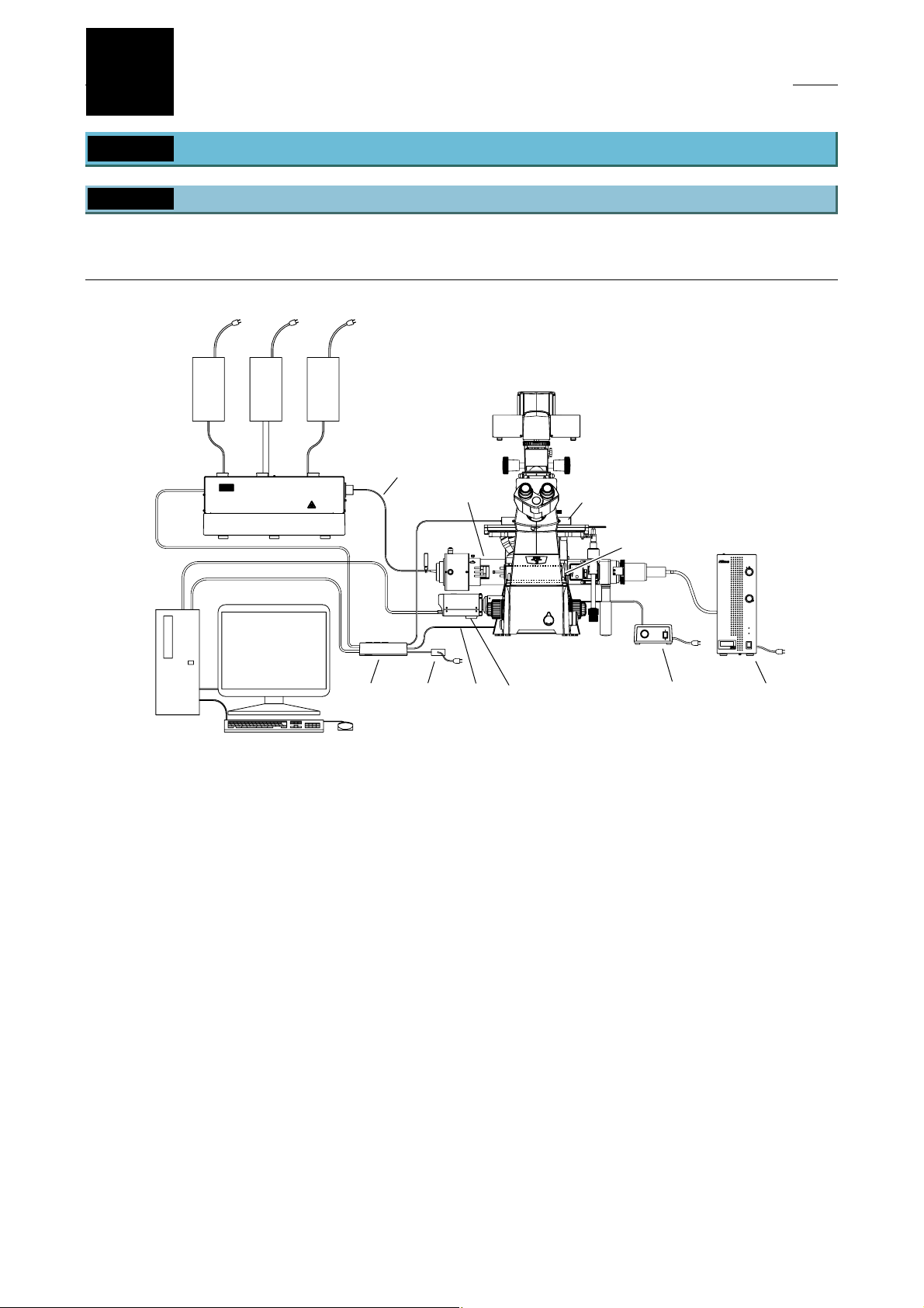
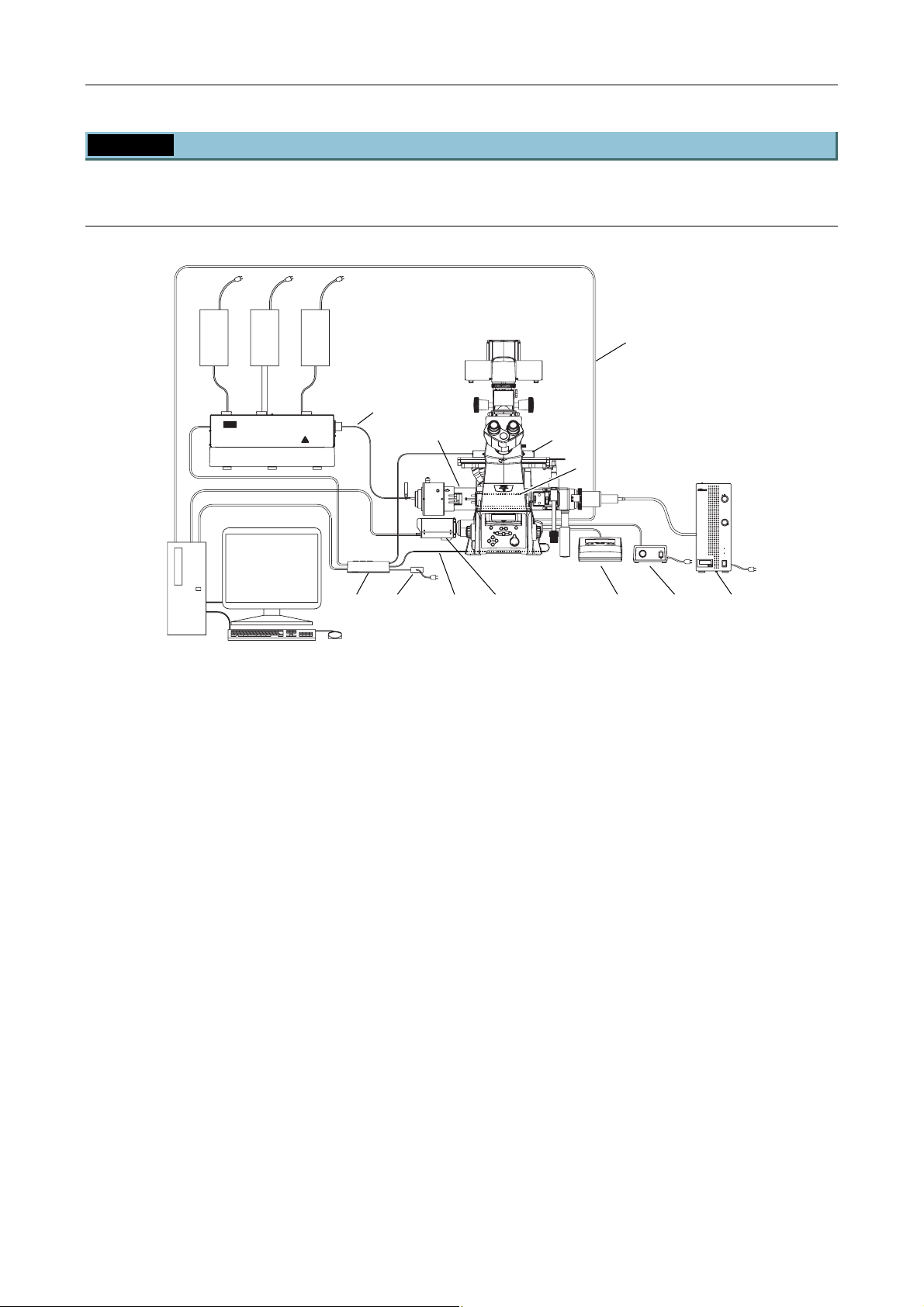
1.1.1 TIRF Illuminator Unit and Ti-U System Overview
TIRF illuminator unit and Ti-U system overview (front view):
When used in combination with two-laser or three-laser unit
(Standard configuration to use the TIRF illuminator unit)
(1)
(4)
(2)
(10)
(12)
(3)
* For details, see Section 8.1, “Overall Configuration,” in Chapter 8, “Specifications and Performance.”
(5)
(6)
(1) Power supply devices for the laser devices
(2) Laser unit (C-LU2, C-LU3, C-LU3EX)
(3) PC
(4) Optical fiber
(5) TI-LUSU shutter unit
(6) AC adapter for the shutter unit
(7) TV camera (video camera)
(8) TI-FLC epi-fl filter turret
(9) Power supply device for the diascopic illumination
(10) TIRF illuminator unit
(11) HG fiber light source
(12) Laser safety cover
(13) Interlock cable
CLASS 3B
–
LASER RADIATION WHEN OPEN
AVOID EXPOSURE TO THE BEAM
CAUTION
(13)
Figure 1.1-1
(7)
(8)
(9)
(11)
1-4
Chapter 1 System Configurations and Part Names
1.1 Overview
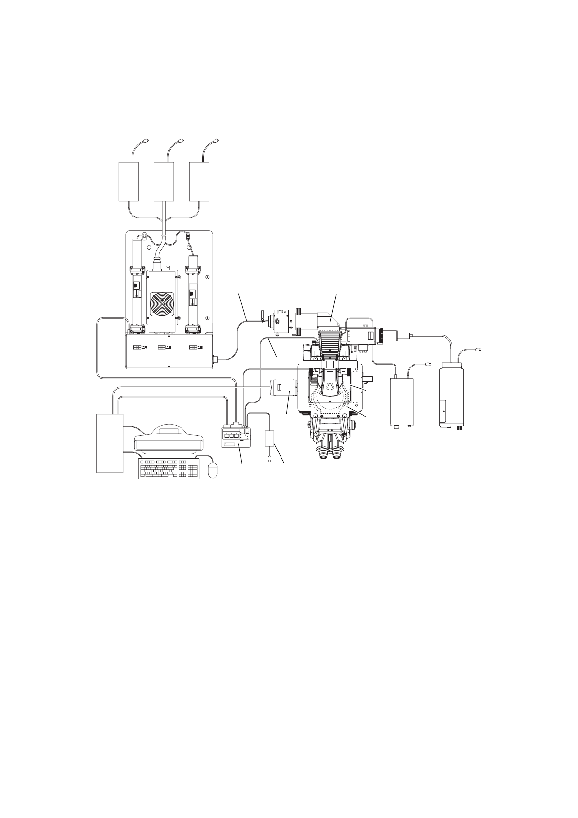
TIRF illuminator unit and Ti-U system overview (top view):
When used in combination with two-laser or three-laser unit
(1)
(2)
(4)
CLASS 3B
–
LASER RADIATION WHEN OPEN
AVOID EXPOSURE TO THE BEAM
CAUTION
INPUT
RS-232C LASER UNIT
12V
SAFETY
1A
LASER SHUTTER
COVER
CLOSE
BINO
CLOSE
POWER
(3)
Exclusive use for TI-TIRF system
Don't use this unit with other systems.
TI-LUSU
(5)
* For details, see Section 8.1, “Overall Configuration,” in Chapter 8, “Specifications and Performance.”
(1) Power supply devices for the laser devices
(2) Laser unit (C-LU2, C-LU3, C-LU3EX)
(3) PC
(4) Optical fiber
(5) TI-LUSU shutter unit
(6) AC adapter for the shutter unit
(7) TV camera (video camera)
(8) TI-FLC epi-fl filter turret
(9) Power supply device for the diascopic illumination
(10) TIRF illuminator unit
(11) HG fiber light source
(12) Laser safety cover
(13) Interlock cable
(13)
(7)
(6)
Figure 1.1-2
(10)
LASERSTRAHLUNG
CLASS 3B
–
–
KLASSE 3B,
WENN ABDECKUNG GEÖFFNET
NICHT DEM STRAHL AUSSETZEN
LASER RADIATION WHEN OPEN
AVOID EXPOSURE TO THE BEAM
VORSICHT
CAUTION
SER RADIATIO
OID EXPOSU
CLASS 3B LASE
AVOID EXPOSURE
LASER LIGHT IS EMITTE
FROM
OBJECTIVE APERT
(12)
(11)
(9)
(8)
1-5
Chapter 1 System Configurations and Part Names
(12)
1.1 Overview
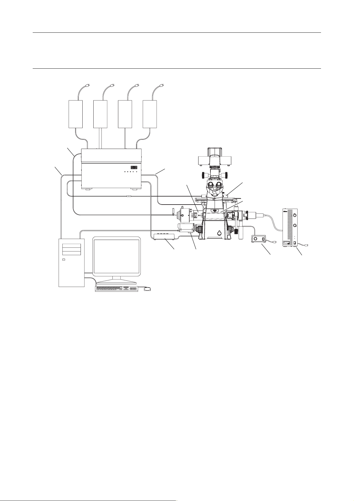
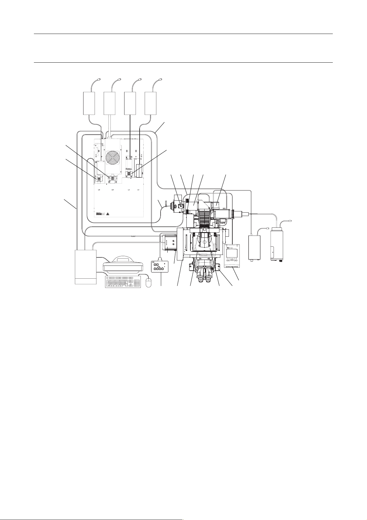
TIRF illuminator unit and Ti-U system overview (front view):
When used with four-laser module A
(Standard configuration to use the TIRF illuminator unit)
(1)
(4)
(2)
(13)
POWER
L4
L3
L1
L2
(3)
* For details, see Section 8.1, “Overall Configuration,” in Chapter 8, “Specifications and Performance.”
(1) Power supply devices for the laser devices
(2) Laser unit (LU4A)
(3) PC
(4) Optical fiber
(5) TI-LU4SU shutter unit LU4
(6) TV camera (video camera)
(7) TI-FLC epi-fl filter turret
(8) Power supply device for the diascopic illumination
(9) TIRF illuminator unit
(10) HG fiber light source
(11) Laser safety cover
(12) Interlock cable
(13) USB cable
(9) (11)
CLASS 3B
–
CAUTION
LASER RADIATION WHEN OPEN
AVOID EXPOSURE TO THE BEAM
(5)
Figure 1.1-3
(7)
(6)
(8) (10)
1-6
Chapter 1 System Configurations and Part Names
(12)
1.1 Overview
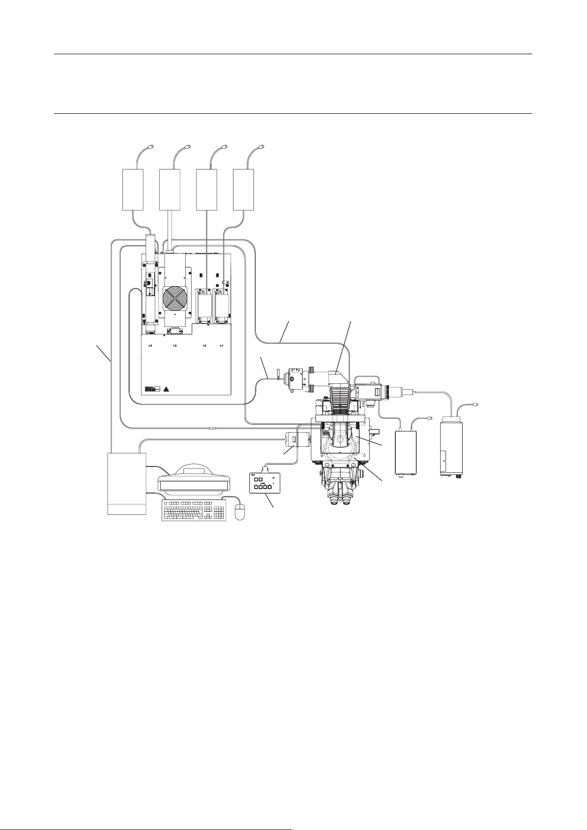
TIRF illuminator unit and Ti-U system overview (top view):
When used with four-laser module A
(Standard configuration to use the TIRF illuminator unit)
(1)
(2)
(9)
(13)
(4)
(3)
TI-LU4SU
* For details, see Section 8.1, “Overall Configuration,” in Chapter 8, “Specifications and Performance.”
(1) Power supply devices for the laser devices
(2) Laser unit (LU4A)
(3) PC
(4) Optical fiber
(5) TI-LU4SU shutter unit LU4
(6) TV camera (video camera)
(7) TI-FLC epi-fl filter turret
(8) Power supply device for the diascopic illumination
(9) TIRF illuminator unit
(10) HG fiber light source
(11) Laser safety cover
(12) Interlock cable
(13) USB cable
CLASS 3B
–
LASER RADIATION WHEN OPEN
AVOID EXPOSURE TO THE BEAM
CAUTION
(6)
LASER
EMISSION
POWER
(5)
Figure 1.1-4
LASERSTRAHLUNG
CLASS 3B
–
–
CAUTION
KLASSE 3B,
WENN ABDECKUNG GEÖFFNET
NICHT DEM STRAHL AUSSETZEN
LASER RADIATION WHEN OPEN
AVOID EXPOSURE TO THE BEAM
VORSICHT
SER RADIATIO
OID EXPOSU
CLASS 3B LASE
AVOID EXPOSURE
LASER LIGHT IS EMITTE
OBJECTIVE APERT
FROM
(8)
(11)
(10)
(7)
1-7
Chapter 1 System Configurations and Part Names
1.1 Overview
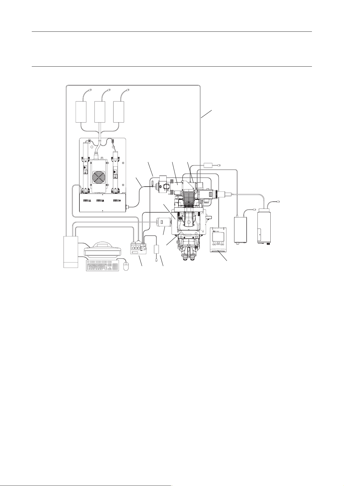
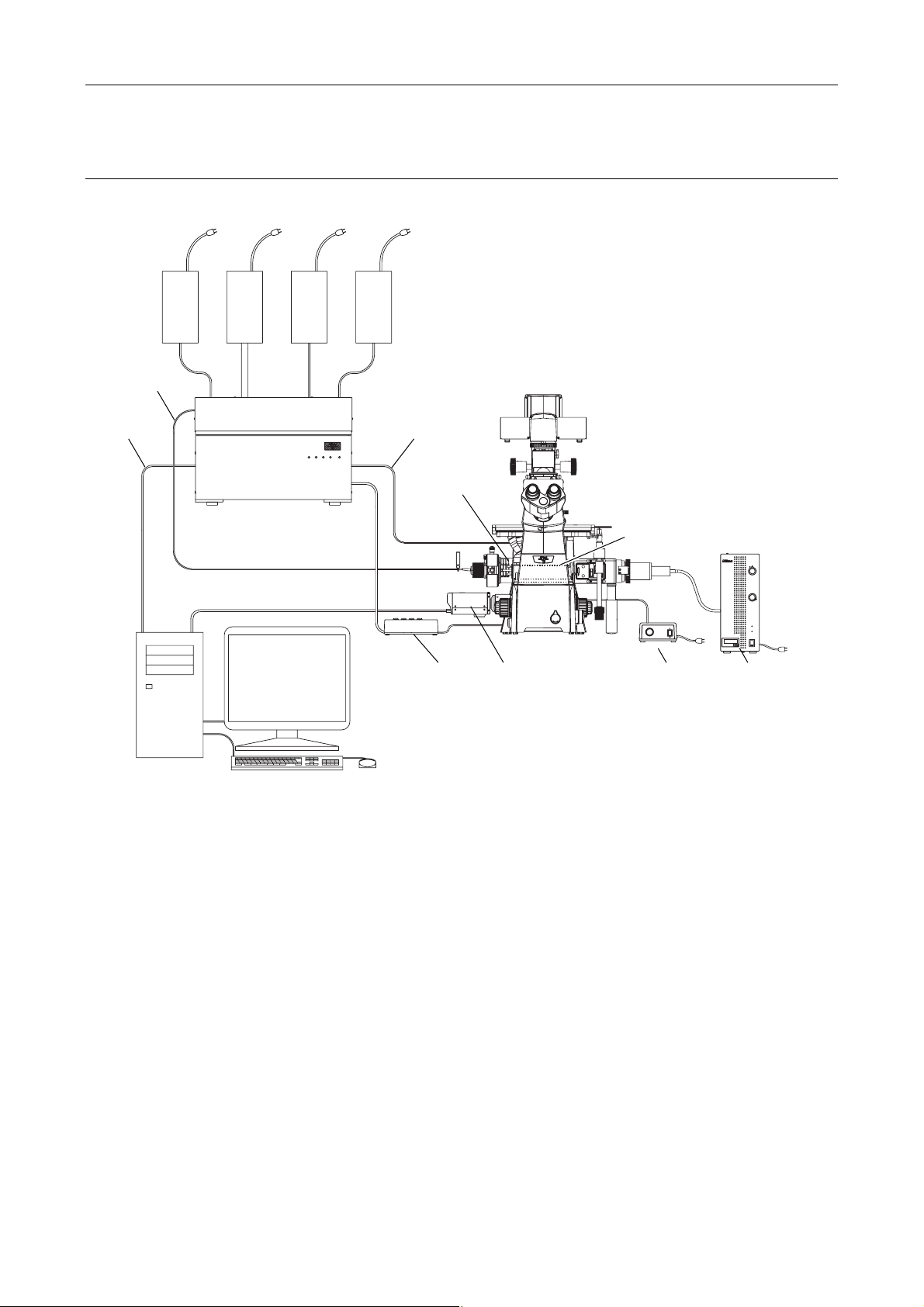
1.1.2 Motorized TIRF Illuminator Unit and Ti-E System Overview
Motorized TIRF illuminator unit and Ti-E system overview (front view):
When used in combination with two-laser or three-laser unit
(Standard configuration to use the motorized TIRF illuminator unit)
(1)
(4)
(2)
CLASS 3B
CLASS 3B
–
–
LASER RADIATION WHEN OPEN
AVOID EXPOSURE TO THE BEAM
CAUTION
LASER RADIATION WHEN OPEN
AVOID EXPOSURE TO THE BEAM
CAUTION
(6) (9) (12)
(3)
(5) (7)
* For details, see Section 8.1, “Overall Configuration,” in Chapter 8, “Specifications and Performance.”
(1) Power supply devices for the laser devices
(2) Laser unit (C-LU2, C-LU3, C-LU3EX)
(3) PC
(4) Optical fiber
(5) TI-LUSU shutter unit
(6) AC adapter for the shutter unit
(7) TV camera (video camera)
(8) TI-FLC-E/HQ motor epi-fl filter turret
(9) Power supply device for the diascopic illumination
(10) Hub controller A (with AC adapter)
(11) Motorized TIRF illuminator unit
(12) HG fiber light source
(13) Remote control pad
(14) Laser safety cover
(15) Interlock cable
(16) USB cable
(11)
(15)
Figure 1.1-5
(16)
(14)
(8)
(13)
1-8
Chapter 1 System Configurations and Part Names
1.1 Overview
Motorized TIRF illuminator unit and Ti-E system overview (top view):
When used in combination with two-laser or three-laser unit
(Standard configuration to use the motorized TIRF illuminator unit)
(1)
(2)
(3)
(4)
RS-232C LASER UNIT
LASER SHUTTER
Exclusive use for TI-TIRF system
Don't use this unit with other systems.
(5)
SAFETY
COVER
CLOSE
BINO
CLOSE
POWER
TI-LUSU
(15)
INPUT
12V
1A
(11)
CLASS 3B
CLASS 3B
–
–
CAUTION
LASER RADIATION WHEN OPEN
AVOID EXPOSURE TO THE BEAM
LASER RADIATION WHEN OPEN
AVOID EXPOSURE TO THE BEAM
CAUTION
(14)
(7)
(8)
(6)
Figure 1.1-6
(16)
(10)
LASERSTRAHLUNG
LASERSTRAHLUNG
CLASS 3B
CLASS 3B
–
–
–
–
CAUTION
LASER RADIATION WHEN OPEN
AVOID EXPOSURE TO THE BEAM
VORSICHT
KLASSE 3B,
WENN ABDECKUNG GEÖFFNET
NICHT DEM STRAHL AUSSETZEN
KLASSE 3B,
WENN ABDECKUNG GEÖFFNET
NICHT DEM STRAHL AUSSETZEN
LASER RADIATION WHEN OPEN
AVOID EXPOSURE TO THE BEAM
VORSICHT
CAUTION
SER RADIATIO
SER RADIATIO
OID EXPOSU
OID EXPOSU
CLASS 3B LASE
CLASS 3B LASE
AVOID EXPOSURE
AVOID EXPOSURE
LASER LIGHT IS EMITTE
LASER LIGHT IS EMITTE
OBJECTIVE APERT
FROM
OBJECTIVE APERT
FROM
(12)
(9)
(13)
* For details, see Section 8.1, “Overall Configuration,” in Chapter 8, “Specifications and Performance.”
(1) Power supply devices for the laser devices
(2) Laser unit (C-LU2, C-LU3, C-LU3EX)
(3) PC
(4) Optical fiber
(5) TI-LUSU shutter unit
(6) AC adapter for the shutter unit
(7) TV camera (video camera)
(8) TI-FLC-E/HQ motor epi-fl filter turret
(9) Power supply device for the diascopic illumination
(10) Hub controller A (with AC adapter)
(11) Motorized TIRF illuminator unit
(12) HG fiber light source
(13) Remote control pad
(14) Laser safety cover
(15) Interlock cable
(16) USB cable
1-9

Chapter 1 System Configurations and Part Names
1.1 Overview
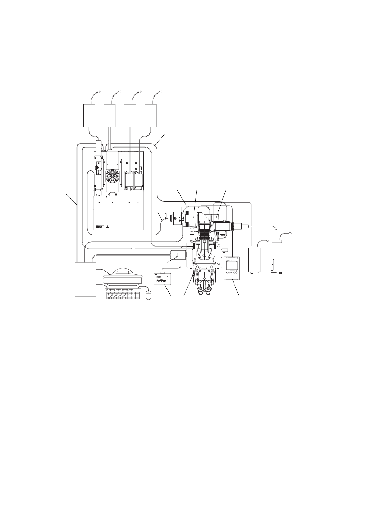
Motorized TIRF illuminator unit and Ti-E system overview (front view):
When used with four-laser module A
(Standard configuration to use the motorized TIRF illuminator unit)
(1)
(4)
(2)
(15)
(15)
POWER
L4
L3
L1
L2
(14)
(10) (13)
(7)
(5)
(3)
* For details, see Section 8.1, “Overall Configuration,” in Chapter 8, “Specifications and Performance.”
(1) Power supply devices for the laser devices
(2) Laser unit (LU4A)
(3) PC
(4) Optical fiber
(5) TI-LU4SU shutter unit LU4
(6) TV camera (video camera)
(7) TI-FLC-E/HQ motor epi-fl filter turret
(8) Power supply device for the diascopic illumination
(9) Hub controller A (with AC adapter)
(10) Motorized TIRF illuminator unit
(11) HG fiber light source
(12) Remote control pad
(13) Laser safety cover
(14) Interlock cable
(15) USB cable
(6) (8) (11)
(12)
Figure 1.1-7
1-10
Chapter 1 System Configurations and Part Names
(9)
1.1 Overview
Motorized TIRF illuminator unit and Ti-E system overview (top view):
When used in combination with four-laser module A
(Standard configuration to use the motorized TIRF illuminator unit)
(1)
(14)
(2)
(15)
(4)
CLASS 3B
CLASS 3B
–
–
CAUTION
LASER RADIATION WHEN OPEN
AVOID EXPOSURE TO THE BEAM
LASER RADIATION WHEN OPEN
AVOID EXPOSURE TO THE BEAM
CAUTION
(6)
(3)
TI-LU4SU
* For details, see Section 8.1, “Overall Configuration,” in Chapter 8, “Specifications and Performance.”
(1) Power supply devices for the laser devices
(2) Laser unit (LU4A)
(3) PC
(4) Optical fiber
(5) TI-LU4SU shutter unit LU4
(6) TV camera (video camera)
(7) TI-FLC-E/HQ motor epi-fl filter turret
(8) Power supply device for the diascopic illumination
(9) Hub controller A (with AC adapter)
(10) Motorized TIRF illuminator unit
(11) HG fiber light source
(12) Remote control pad
(13) Laser safety cover
(14) Interlock cable
(15) USB cable
(10)
(7)
LASER
EMISSION
POWER
(5)
(15)
Figure 1.1-8
(12)
(8)
(11)
1-11
Chapter 1 System Configurations and Part Names
1.1 Overview
1.1.3 Motorized TIRF Illuminator Unit, LU4A, N-STORM, and Ti-E System
Overview
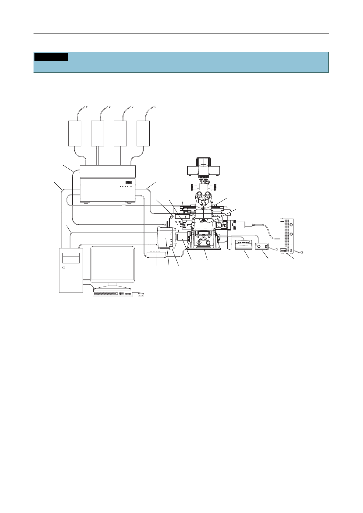
Motorized TIRF illuminator unit, LU4A, N-STORM, and Ti-E system overview (front view)
(Standard configuration to use the Motorized TIRF illuminator unit)
(1)
(4)
(2)
(15)
POWER
L4
L3
L1
L2
(14)
(10)
(20)(19)
(13)
(7)
(15)
(3)
* For details, see Section 8.1, “Overall Configuration,” in Chapter 8, “Specifications and Performance.”
(1) Power supply devices for the laser devices
(2) Laser unit (LU4A)
(3) PC
(4) Optical fiber
(5) TI-LU4SU shutter unit LU4
(6) EM-CCD camera
(7) TI-FLC-E/HQ motor epi-fl filter turret
(8) Power supply device for the diascopic
illumination
(9) Hub controller A (with AC adapter)
(10) Motorized TIRF illuminator unit
(11) HG fiber light source
(12) Remote control pad
(13) Laser safety cover
(6)
(5)
Figure 1.1-9
(17)
(16) (18)
(12)
(8) (11)
(14) Interlock cable
(15) USB cable
(16) 3D-STORM port
(17) DSC support columns (2 pieces)
(18) Ti-E fixing plate
(19) STORM slider
(20) Lambda plate slider
(21) 405-nm laser adapter with ND
(See Figure 1.1-10 for the location.)
(22) 457-nm laser adapter with ND
(See Figure 1.1-10 for the location.)
(23) 561-nm laser adapter with ND
(See Figure 1.1-10 for the location.)
1-12
Chapter 1 System Configurations and Part Names
(9)
1.1 Overview
Motorized TIRF illuminator unit, LU4A, N-STORM, and Ti-E system overview (top view)
(Standard configuration to use the Motorized TIRF illuminator unit)
(1)
(14)
(22)
(2)
transportation.
Fix the laser unit with
four blocks during
(23)
(15)
(3)
* For details, see Section 8.1, “Overall Configuration,” in Chapter 8, “Specifications and Performance.”
(1) Power supply devices for the laser devices
(2) Laser unit (LU4A)
(3) PC
(4) Optical fiber
(5) TI-LU4SU shutter unit LU4
(6) EM-CCD camera
(7) TI-FLC-E/HQ motor epi-fl filter turret
(8) Power supply device for the diascopic
illumination
(9) Hub controller A (with AC adapter)
(10) Motorized TIRF illuminator unit
(11) HG fiber light source
(12) Remote control pad
(21)
(4)
CLASS 3B
CLASS 3B
–
–
CAUTION
LASER RADIATION WHEN OPEN
AVOID EXPOSURE TO THE BEAM
LASER RADIATION WHEN OPEN
AVOID EXPOSURE TO THE BEAM
CAUTION
(6)
TI-LU4SU
LASER
EMISSION
POWER
(17)
(5)
(16) (13) (18)
Figure 1.1-10
(15)
(20)(19)
(10)
(11)
(8)
(12)
(7)
(13) Laser safety cover
(14) Interlock cable
(15) USB cable
(16) 3D-STORM port
(17) DSC support columns (2 pieces)
(18) Ti-E fixing plate
(19) STORM slider
(20) Lambda plate slider
(21) 405-nm laser adapter with ND
(22) 457-nm laser adapter with ND
(23) 561-nm laser adapter with ND
1-13
Chapter 1 System Configurations and Part Names
1.1 Overview
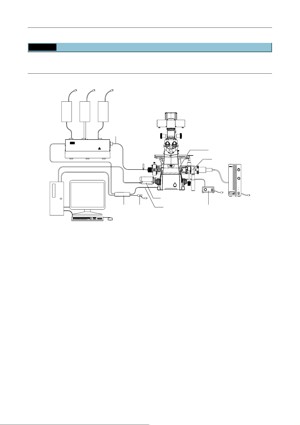
1.1.4 TI-PAU Photo Activation Illuminator Unit and Ti-U System Overview
Photo activation illuminator unit and Ti-U (front view):
When used in combination with two-laser or three-laser unit
(Standard configuration to use the photo activation illuminator unit)
(1)
(4)
(2)
(3)
* For details, see Section 8.1, “Overall Configuration,” in Chapter 8, “Specifications and Performance.”
(1) Power supply devices for the laser devices
(2) Laser unit (C-LU2, C-LU3, C-LU3EX)
(3) PC
(4) Optical fiber
(5) TI-LUSU shutter unit
(6) AC adapter for the shutter unit
(7) TV camera (video camera)
(8) TI-FLC epi-fl filter turret
(9) Power supply device for dia illumination
(10) Photo activation illuminator unit
(11) HG fiber light source
(12) Interlock cable
(5)
CLASS 3B
–
CAUTION
LASER RADIATION WHEN OPEN
AVOID EXPOSURE TO THE BEAM
(6)
Figure 1.1-11
(7)
(12)
(9)
(8)
(10)
(11)
1-14
Chapter 1 System Configurations and Part Names
(12)
1.1 Overview
Photo activation illuminator unit and Ti-U (top view):
When used in combination with two-laser or three-laser unit
(Standard configuration to use the photo activation illuminator unit)
(1)
(2)
(4)
CLASS 3B
CAUTION
LASER RADIATION WHEN OPEN
AVOID EXPOSURE TO THE BEAM
(10)
RS-232C LASER UNIT
LASER SHUTTER
(3)
Exclusive use for TI-TIRF system
Don't use this unit with other systems.
* For details, see Section 8.1, “Overall Configuration,” in Chapter 8, “Specifications and Performance.”
(1) Power supply devices for the laser devices
(2) Laser unit (C-LU2, C-LU3, C-LU3EX)
(3) PC
(4) Optical fiber
(5) TI-LUSU shutter unit
(6) AC adapter for the shutter unit
(7) TV camera (video camera)
(8) TI-FLC epi-fl filter turret
(9) Power supply device for dia illumination
(10) Photo activation illuminator unit
(11) HG fiber light source
(12) Interlock cable
(5)
INPUT
12V
SAFETY
1A
COVER
CLOSE
BINO
CLOSE
POWER
TI-LUSU
(7)
LASER RADIATION
AVOID EXPOSURE TO BE
CLASS 3B LASER PROD
AVOID EXPOSURE
LASER LIGHT IS EMITTED
FROM
OBJECTIVE APERTURE
(6)
Figure 1.1-12
LASERSTRAHLUNG
CLASS 3B
CAUTION
LASER RADIATION WHEN OPEN
AVOID EXPOSURE TO THE BEAM
VORSICHT
KLASSE 3B,
WENN ABDECKUNG GEFFNET
NICHT DEM STRAHL AUSSETZEN
(8)
(9)
(11)
1-15
Chapter 1 System Configurations and Part Names
(11)
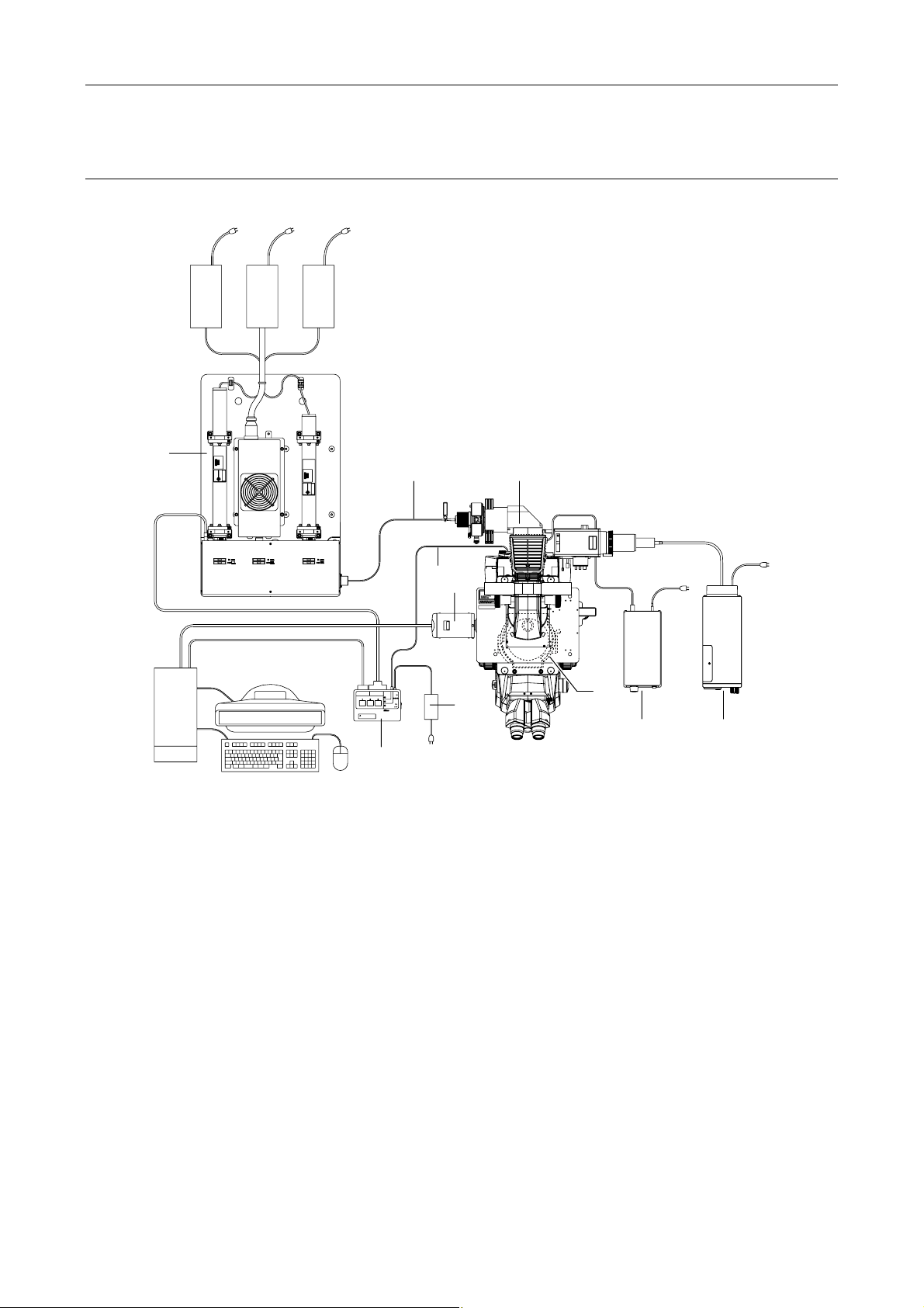
1.1 Overview
Photo activation illuminator unit and Ti-U (front view):
When used with four-laser module A
(Standard configuration to use the photo activation illuminator unit)
(1)
(4)
(12)
(2)
POWER
L3
L1
L4
L2
(3)
Figure 1.1-13
* For details, see Section 8.1, “Overall Configuration,” in Chapter 8, “Specifications and Performance.”
(1) Power supply devices for the laser devices
(2) Laser unit (LU4A)
(3) PC
(4) Optical fiber
(5) TI-LU4SU shutter unit LU4
(6) TV camera (video camera)
(7) TI-FLC epi-fl filter turret
(8) Power supply device for the diascopic illumination
(9) Photo activation illuminator unit
(10) HG fiber light source
(11) Interlock cable
(12) USB cable
(5)
(9)
(7)
CLASS 3B
–
CAUTION
LASER RADIATION WHEN OPEN
AVOID EXPOSURE TO THE BEAM
(6) (8) (10)
1-16
 Loading...