

Nikon Eclipse Ni-U Instruction Manual

M570 E 11.8.NF.1 (2/2)
Assembly
Troubleshooting
Maintenance and
Upright Microscope
Instruction Manual
Assembly/Maintenance
Storage
Specifications


Introduction
Introduction
Thank you for purchasing a Nikon product.
This instruction manual is written for users of the Nikon ECLIPSE Ni-U microscope. To ensure correct usage, read this
manual carefully before operating this product.
● No part of this manual may be reproduced or transmitted in any form without prior written permission from Nikon.
● The contents of this manual are subject to change without notice.
● The equipment described in this manual may differ from the actual product in its appearance.
● Although every effort has been made to ensure the accuracy of this manual, errors or inconsistencies may remain. If
you note any points that are unclear or incorrect, please contact your nearest Nikon representative.
● Some of the equipment described in this manual may not be included in the set you have purchased.
● If you intend to use any other equipment with this product, read the manual for that equipment too.
● If this equipment is used in a manner not specified by the manufacturer, the protection provided by the equipment may
be impaired.
● Training: This product can be used without special training, provided that this manual is read thoroughly before use. Kindly
contact your nearest Nikon representative if you have any questions, find any errors, or wish to provide us with your
opinion.
i
Introduction
Contents of the Manual
The instruction manual for ECLIPSE Ni-U is provided as two volumes.
Operation
Safety Precautions
Components
Microscopy Procedures
Operation Flowchart
Bright/Dark-field Microscopy
Epi-fluorescence Microscopy
Differential Interference Contrast Microscopy
Phase Contrast Microscopy
Motorized Bright-field Microscopy
Motorized Epi-fluorescence Microscopy
Individual Operations
Symbols Used in This Manual
The following symbols are used in this manual.
Symbols for Safety
WARNING
CAUTION
Other Symbols
Highlights important information that should be noted for safety. Read “Safety Precautions” for details.
Assembly/Maintenance (This manual)
Assembly
Troubleshooting
Maintenance and Storage
Specifications
Before reading the “Assembly/Maintenance” manual,
read the “Safety Precautions” in the “Operation”
manual.
Indicates information you should note or comply with to prevent defects or malfunction of this product.
Indicates information you should be aware of in using this product, as well as other useful information.
ii

Summary of Contents
g
Summary of Contents
Introduction
Contents of the Manual
Symbols Used in This Manual
(See the next page for the detailed contents.)
Assembly
Troubleshooting
Maintenance and Storage
Assembly
Troubleshooting
and Stora
e
Specifications
Specifications Maintenance
iii

Contents
Contents
Introduction .........................................................................................................................i
Contents of the Manual ....................................................................................................ii
Symbols Used in This Manual..........................................................................................ii
Summary of Contents ....................................................................................................... iii
Assembly.................................................................................................. 1
1 ECLIPSE Ni-U System Configuration .......................................................................2
2 Components List ....................................................................................................... 3
3 Assembly Method......................................................................................................4
Introduction ...................................................................................................................... 4
[1] Check the input voltage...................................................................................... 4
[2] Attach the DIA motorized shutter (optional). ...................................................... 5
[3] Attach the lamp. ................................................................................................. 5
[4] Attach the lamphouse for dia-illumination. ......................................................... 5
[5] Attach the standard arm/contact arm................................................................. 6
[6] Attach the epi-fluorescence cube turret and epi-fluorescence attachment
(required for epi-fluorescence microscopy)........................................................ 7
■ Attaching a filter cube ............................................................................... 8
■ Replacing excitation and barrier filters ..................................................... 9
■ Attaching a light shielding plate ................................................................ 9
[7] Attach the quadrocular tilting tube and DSC zooming port
for quadrocular tube. ........................................................................................ 10
[8] Attach the EPI motorized shutter (optional). .................................................... 10
[9] Attach eyepieces. ..............................................................................................11
[10] Attach the substage...........................................................................................11
[11] Attach the condenser holder. ........................................................................... 12
[12] Attach the stage. .............................................................................................. 12
[12.1] For standard stage .......................................................................... 12
[12.2] For rotatable ceramic coated stage................................................. 12
[13] Attach the condenser........................................................................................ 13
■ Attaching the optical module to the universal condenser....................... 13
■ Attaching the DIC module to DIC condenser oil..................................... 17
[14] Attach the nosepiece........................................................................................ 19
[15] Attach the objective. ......................................................................................... 19
[16] Attach the DIC rotation polarizer unit (required for differential interference
contrast microscopy). ....................................................................................... 19
[17] Attach the eyelevel riser (optional)................................................................... 20
[18] Attach a camera and connect the DS camera control unit (optional). ............. 20
[18.1] When attaching to the DSC port for the ergonomic binocular tube 20
[18.2] When attaching to the DSC zooming port for quadrocular tube ..... 21
[18.3] When attaching to the quadrocular tilting tube................................ 21
[18.4] When attaching a camera to the trinocular tube ............................. 21
[19] Replace the ND filter (optional)........................................................................ 22
[20] Connect the motorized device cable................................................................ 22
[21] Connect the power cord. .................................................................................. 24
Troubleshooting..................................................................................... 25
1 Optical System and Operation ................................................................................26
1.1 General............................................................................................................. 26
1.2 Epi-fluorescence Microscopy ........................................................................... 30
1.3 Differential Interference Contrast Microscopy.................................................. 31
iv

Contents
1.4 Phase Contrast Microscopy ............................................................................. 32
2 Electrical Requirements ..........................................................................................33
2.1 General............................................................................................................. 33
2.2 Epi-fluorescence Microscopy ........................................................................... 34
Maintenance and Storage ..................................................................... 35
1 Replacing the Lamp ................................................................................................36
2 Cleaning ..................................................................................................................37
2.1 Cleaning Lenses............................................................................................... 37
2.2 Cleaning Parts Other than the Lens................................................................. 37
2.3 Cleaning Immersion Oil.................................................................................... 38
2.4 Decontaminating the Product........................................................................... 38
3 Transportation .........................................................................................................38
4 Storage....................................................................................................................38
5 Regular Inspections (Charged) ...............................................................................38
Specifications ........................................................................................ 39
1 Microscopy (Principles) ...........................................................................................40
2 Performance Properties .......................................................................................... 40
3 Physical Properties .................................................................................................43
v

Contents
vi

1
Chapter
1
Assembly
This chapter contains an Ni-U system configuration diagram, a list of its components, and explains how to assemble the
system.
Read appropriate notes such as CAUTION “9 Cautions on assembling and installing the product” at the beginning of
the separately provided instruction manual “Operation” or “4 Installation location” in “Notes on Handling the Product” in the
same manual before you work on assembling.
Assembly
■ Assembly tools provided with the microscope
• Hex driver x3: 2 mm across flats x3
• Hex wrench x2: 3 and 4 mm across flats
1
Chapter 1 Assembly
r
r
r
Assembly
1
Centering telescope
Binocular tube
Eyelevel riser
Analyzer unit
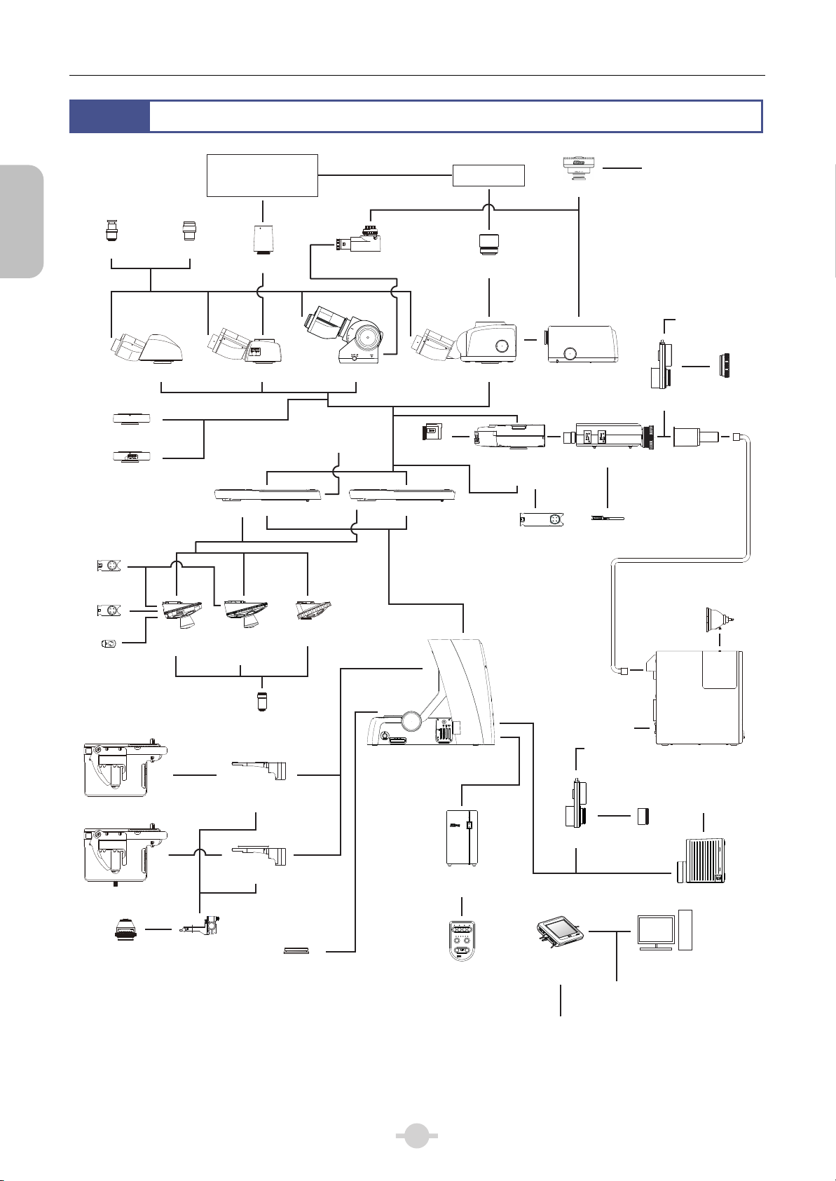
ECLIPSE Ni-U System Configuration
ENG mount camera
C mount camera
Photomicrography device
CFI eyepiece
TV adapter
Trinocular tube
DSC port for ergonomic
binocular tube
Ergonomic tube
To control box B
Contact arm Standard arm
Various adapters
Tube adapter for
quadrocular tube
Quadrocular tilting tube
Filter
cube
Epi-fluorescence
cube turret*2
FL/DIC
analyzer
DS camera head
DSC zooming port
Epi-fluorescence
attachment
Excitation
balancer
Motorized shutter
D-FB
Camera cable to
DS-U3 or DS-L3
Motorized
shutter cable to
control
box B
Motorized shutte
HG adapter
adapter
HG fibe
Analyzer
slider
Lambda plate
DIC slider
DIC
nosepiece*1
Nosepiece
with
analyzer slot
Nosepiece
*1
CFI objective
Ni-U main body
Substage fo
holder
rotatable ceramic
coated stage
Substage
Polarizer
unit
Control
box B
EPI FL INTSL
DIA
SHUTTER OPEN
12481632
INTSL ND
OBJ FL
CONTROL
NI-SRCP
MADE IN JAPAN
Simple remote
control pad
Rotatable ceramic
coated stage
Stage
Achr-Apl N.A=1.4
0.20.40.60.81.01.21.4
Condenser
*1: A contact arm is required to use a motorized/intelligent nosepiece.
Condenser
*2: A contact arm is required to use a motorized/intelligent epi-fluorescence cube turret.
*3: DS-U3 DS camera control unit can not be connected via USB.
RS-232C cable to
control box B for
motorized operation
Motorized
shutter cable to
control
box B
Motorized
shutter
DS-L3/
DS-U3 Camera
Control Unit
Camera trigger cable to
Ni-U main body or
control box B
USB cable to
control box B*3
Mercury lamp
Motorized
shutter
adapter
HG precentered
fiber illuminator
To Ni-U
main body
Lamphouse
PC
2
Chapter 1 Assembly
2
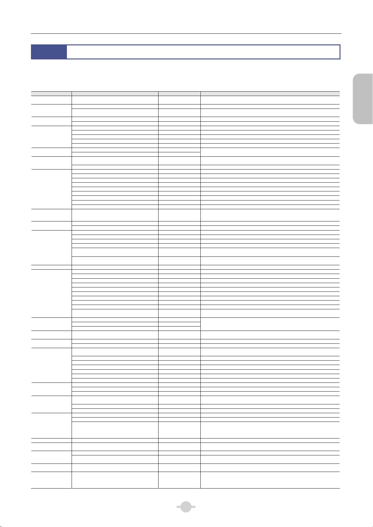
The ECLIPSE Ni-U components are shown in the table below.
Depending on when you purchased the ECLIPSE Ni-U, there may be devices not yet available for use and devices not
listed that are already available for use. Contact your nearest Nikon representative for details.
Device Device Name Model Remarks
Microscope main
body
Illuminator for
dia-illumination
Arm
Tube
DSC port
Eyepiece
Nosepiece
Objective CFI objective
Substage
Stage
Condenser holder Condenser holder NI-CH
Condenser
Epi-fluorescence
cube turret
Epi-fluorescence
attachment
Mercury lamp
illuminator
Analyzer unit/
Slider
Polarizer unit
Shutter
Controller
Eyelevel riser Eyelevel riser C-ER
Variable intermediate
magnification unit
DSC retention
support
Tube adapter for
quadrocular tube
TV adapter TV adapter
Components List
ECLIPSE Ni-U (12V 1 00W 100-240V power sup ply
for illumination integrated)
Precentered lampho use (12V 100W) NI-LH
Halogen lamp (100W)
Standard arm NI-SAM Combine with a manual model such as manual nosepiece
Contact arm NIU-CAM Combine with a motorize d models such as intelligent /motorized nosepiec e
Binocular tube C-TB C-TBM mildew-proof type also available
Trinocular eyepiece tube F C-TF C-TFM mildew-proof type also available
Trinocular eyepiece tube T C-TT
Ergonomic tube C-TE2
Quadrocular tilting tube NI-TT
DSC port for ergonomic binocular tube C-TEP2
DSC zooming port for quadrocular tube NI-RPZ
CFI eyepiece
Centering telescope C-CT
Universal quintuple nosepiece L-NU5
BD quintuple nosep iece L-NBD5
Sextuple nosepiece C-N
Sextuple nosepiece with analyzer slot C-NA
Sextuple DIC nosepiec e D -ND6
Intelligent DIC sextuple nosepiece NI-ND6-I
Intelligent Septuple nosepiece NI-N7-I
Motorized DIC sextuple nosepiece NI-ND6-E
Motorized septuple nosepiece NI-N7-E
Substage NI-SS Rotatable ceramic coated stage can not be attached
Substage for rotatable ceramic coated stage NI-SSR
Right handle stage with 2S holder C-SR2S
Left handle stage with 2S hold er C-SL2S
Right handle ceramic coated stage with 1S holder C-CSR1S
Left handle ceramic coated stage with 1S holder C-CSL1S
NI-U right handle rotatable ceramic coated stage
with holder
NI-U left handle rotatable ceramic coated stage with
holder
Dark field condenser (Oil) and (Dry)
C-C aplanatic condenser
C-C achromat conden ser No.9
C-C abbe condenser No.9
X LWD condenser
C-C slide achro conde nser 2-100x
C-C achromat swing-o ut condenser 1-100x
C-C phase turret condenser Cannot be used when rotatable ceramic coated stage is attached.
DIC condenser (Oil) D-CUO Used with OIL DIC module
Universal condenser (Dry) NI-CUD
Cube turret NI-FLT6
Intelligent epi-f luorescence cube t urret NI-FLT6-I
Motorized epi-flu orescence cube turret NI-FLT6-E
Epi-fluorescence attachment NI-FLEI D-FB excitation balancer attachable.
HG precentered fiber illuminator C-HGFI
Motorized HG precentered fiber illuminator C-HGFIE
Analyzer slider for DI C D-DA
Analyzer tube for simple polarization C-ISA Combined with C-SP polarizer unit.
Analyzer tube for first -order red compensation C-IA Combined with C-TP polar izer unit.
Analyzer slider for simple polarization D-SA
Analyzer slider for first-order red compensation C-AS
DIC slider D-C Can be attached to D-ND6, NI-ND6-I, or NI-ND6-E nosepiece.
Lambda plate D-LP Can be attached to D-ND6, NI-ND6-I, or NI-ND6-E nosepiece.
DIC rotatable polarizer unit D-DP
Polarizer unit for simple polarization C-SP
Polarizer unit for first-order red compensation C-TP
Motorized shutter NI-SH-E
Motorized shutter adapter for upright epi-fl NI-SHAEP-U
Motorized shutter adapter for dia-illumination NI-SHADI
Control box B NI-CTLB
Simple remote control pad NI-SRCP
DS-L3/DS-U3 camera control unit
Variable intermediate magnif ication unit Y-IM
DSC support column NI-RPS
DSC adapter A and B
Tube adapter for quadrocular tube C-TAQ
ECLIPSE Ni-U
PHILIPS 7724
OSRAM HLX 64623
CFI
CFI UW
CFI
LU Plan Fluor Epi
LU Plan Fluor BD
NIU-CSRR2
NIU-CSLR2
DS-L3
DS-U3
NI-RPSAA
NI-RPSAB
Y-T V
Y-T V5 5
Connected to Nikon DS camera head or other C mount camera. Nikon DS camera
head is controlled from DS-L3/DS-U3.
LU Plan Fluor Epi/BD can be attached to the L-NU5 or L-NBD5 nosepiece.
LU nosepiece adapter is required to attach a non-BD obje ctive to L-NBD5.
Supports DRY DIC module, PH module, dark field module, NI-CALN1 2-4x auxiliary
lens, D-C 2-4x auxiliary lens
A filter cube and NI-FA FL/DIC analyzer attachable.
Can be attached to C-NA, D-ND6, NI-ND6-I, NI-N7-I, NI-ND6-E, or NI-N7-E
nosepiece.
For connection, NI-S HCL motorized shutter cable is req uired and is connected to t he
control box B.
DS-L3 is connected to the control box B via USB cable
DS-L3/DS-U3 is con nected to the Ni-U m ain body or the contr ol box B via C-CTC
camera trigger cable L3/U3
DS camera I/F cable is used to connect to the camera
Can be attached to the quadrocular tilting tube. Attach a C mount camera, ENG mount
camera or a photomicrography device via various adapters.
Y-TV can be attached to C-TF or C-TT trinocular tube. C onnect a C mount camera,
ENG mount camera, or photomicroscopy device with an adapter.
Y-TV55 can be attached to C-TF or C-TT trinocular tube. Connect a C mount cam era
with C mount adapter 0.55x.
Assembly
3
Chapter 1 Assembly
Assembly
3
Assembly Method
Introduction
Ni-U is a manual microscope. Basically, a manual model is attached for each device consisting the microscope.
However, for nosepiece, epi-fluorescence cube turret, and HG precentered fiber illuminator, motorized models
can be attached. In this case, contact arm, control box B, and simple remote control pad are required. In addition,
in order to configure information for motorized devices, DS-L3 DS camera control unit must be connected.
Motorized devices on Ni-U can be controlled from DS-L3.
Note that when using epi-fluorescence cube turrets by layering, motorized/intelligent epi-fluorescence cube turret
can only be used in 1st layer.
Assemble the device according to the following procedure.
Precautions for connecting cables
Cable connections are required for some motorized devices.
Be sure to turn off the power to the microscope and peripheral devices before starting cable connection.
Cable connections are described in each assembly step. Nikon recommends connecting cables at the end of the
assembly. See “20 Connect the motorized device cable.” for the connector connections.
Information setting regarding motorized models
Set information of the motorized devices or optical element attached on the microscope setup menu for the DS-L3 DS Camera
Control Unit. (See Chapter 3 “19 Operations on DS-L3” - “19.1 Setting Up the Microscope.)
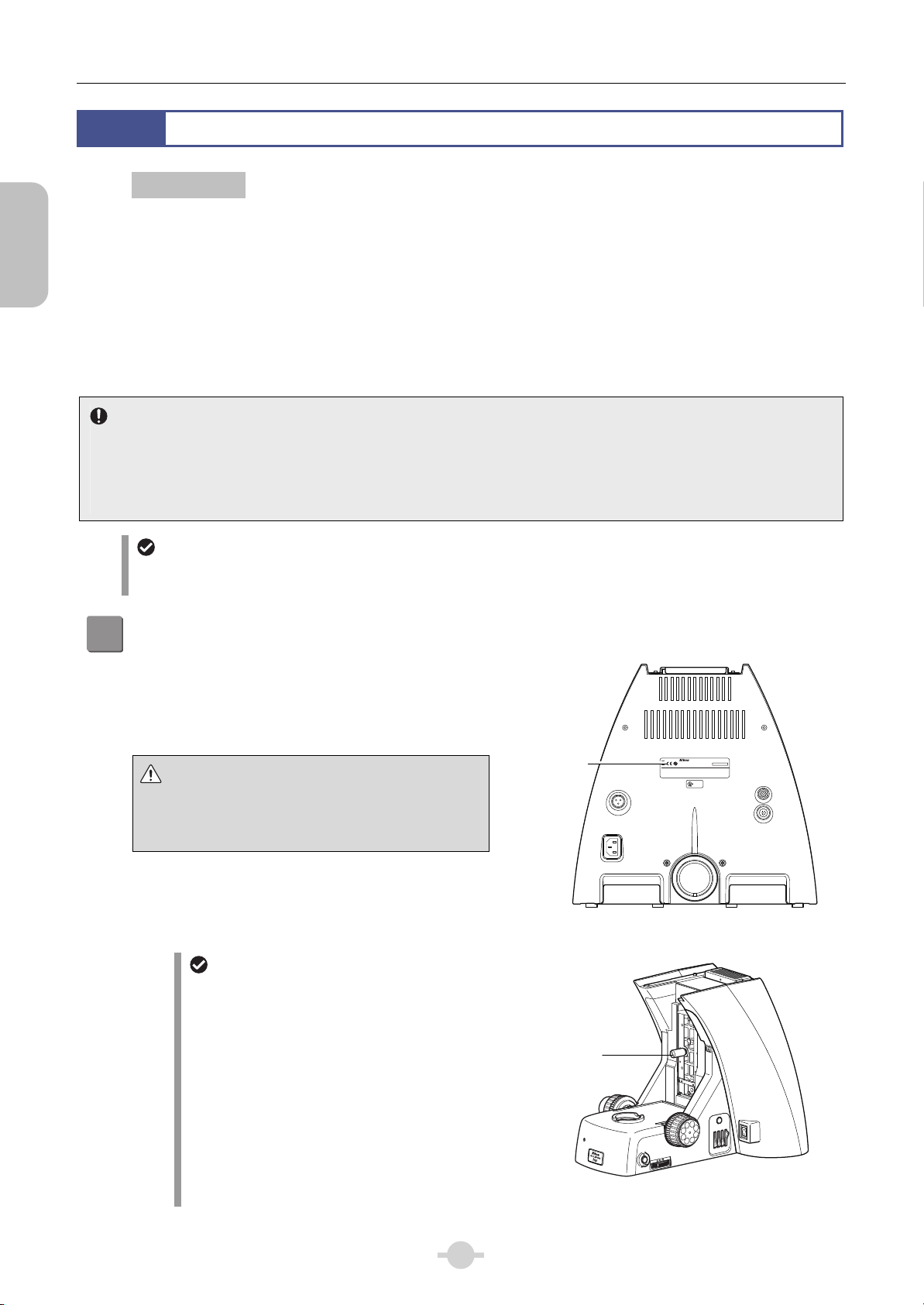
Check the input voltage.
1
Check the input voltage indicated on the back of the
microscope. Use the microscope only if the indicated
input voltage matches the power supply voltage for the
area in which the microscope will be used.
WARNING
Input voltage
If the indicated voltage and the supplied voltage differ, do
not attempt to use the microscope. Contact your nearest
Nikon representative.
Unlocking the elevating section
Tool: flathead screwdriver
After you confirm that the input voltage is correct,
loosen and remove the tightening screw at the front
of the elevating section.
label
Tightening
screw
MODEL ECLIPSE Ni-U
NIKON CORPORATION
100–240V~
920001
TOKYO, JAPAN
1.7A
MADE IN JAPAN
50/60Hz
This device complies with Part 15 of the FCC Rules. Operation is subject to the following two conditions:
(1) this device may not cause harmful interference, and
(2) this device must accept any interference received, including interference that may cause undesired operation.
This Class A digital apparatus complies with Canadian ICES-003.
Cet appareil numérique de la classe A est confirme à la norme NMB-003 du Canada.
INSPECTION
EQUIPMENT
4N75
LAMP
DC12V 100W
Checking the input voltage
(Microscope rear view)
LAMP CTRL
(BOX B)
DSC
4
NCB
ND
ND
11
32
8
POWER
OUT
IN
Unlocking the elevating section
Chapter 1 Assembly
Attach the DIA motorized shutter (optional).
2
The motorized shutter is attached by Nikon.
Contact your nearest Nikon representative when the DIA motorized shutter needs to be attached or removed.
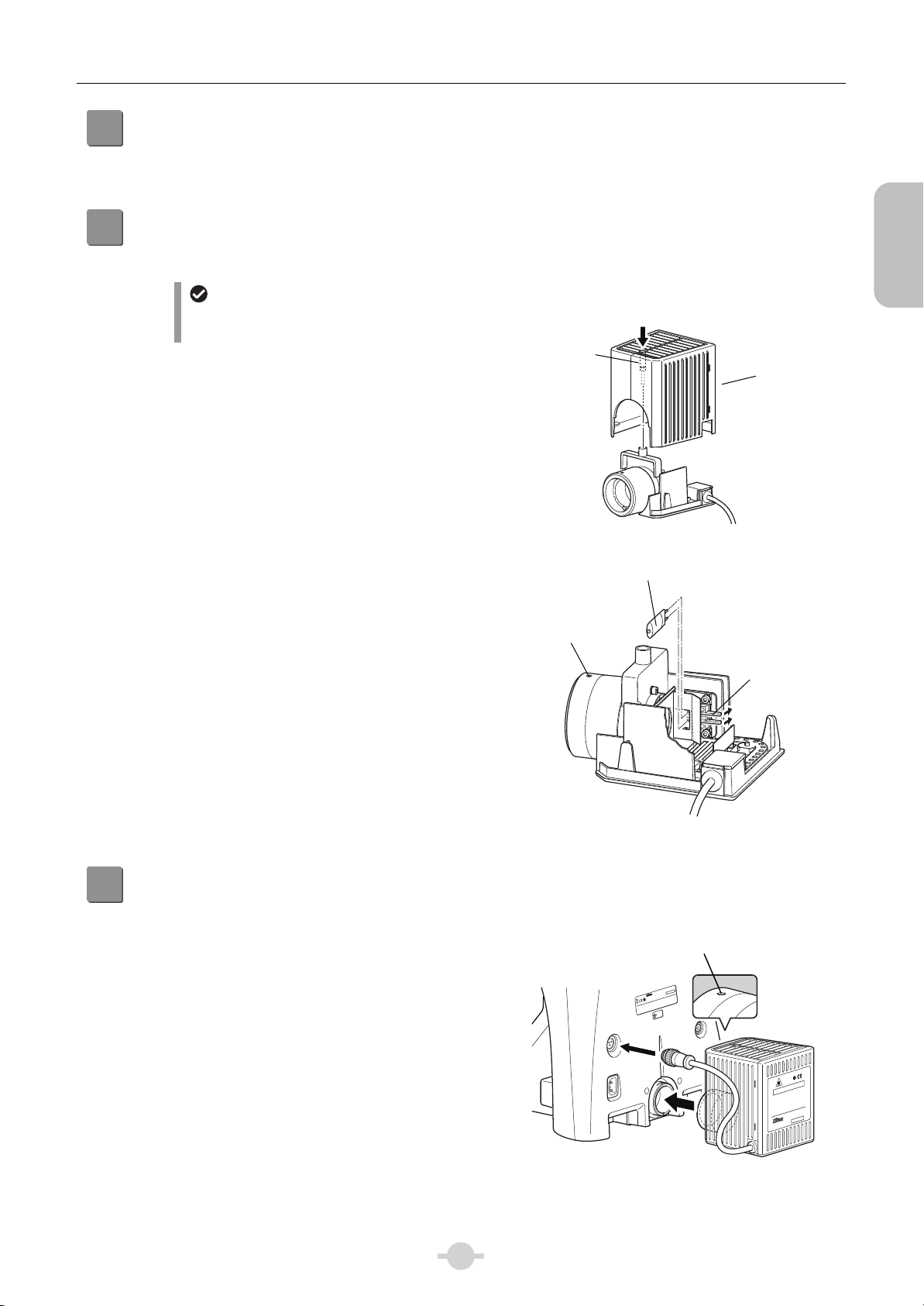
Attach the lamp.
3
Tool: Hex wrench (3 mm across flats)
Lamp handling precautions
Avoid touching the glass surface of the lamp with
your bare hands.
(1) Loosen the lamphouse cover fixing screw and lift up
Fixing screw
the cover to remove.
(2) Insert the lamp clamp lever to open the socket pin
hole. Attach the lamp while holding down the lever.
Put the lamp clamp lever back to its original position.
Designated lamp: PHILIPS7724
or OSRAM HLX64623
(3) Reattach the cover back to its original position and
tighten the lamphouse cover fixing screw.
Insert the hex wrench and
loosen the fixing screw.
Lamphouse
cover
Removing the lamphouse cover
Lamp
Assembly
Lamphouse
fixing screw
Attach the lamphouse for dia-illumination.
4
Tool: Hex driver (2 mm across flats)
(1) Insert the lamphouse at the rear of the microscope
and tighten the fixing screws.
(2) Connect the dia-illumination lamphouse cable to the
LAMP connector on the rear of the main body.
Attaching the lamp
Lamphouse fixing screw
MODEL ECLIPSE Ni-U
920001
100–240V~
MADE IN JAPAN
1.7A
NIKON CORPORATION
50/60Hz
LAMP
DC12V 100W
TOKYO, JAPAN
This device complies with Part 15 of the FCC Rules. Operation is subject to the following two conditions:
(1) this device may not cause harmful interference, and
(2) this device must accept any interference received, including interference that may cause undesired operation.
This Class A digital apparatus complies with Canadian ICES-003.
Cet appareil numérique de la classe A est confirme à la norme NMB-003 du Canada.
DSC
INSPECTION
EQUIPMENT
4N75
LAMP CTRL
)
(
BOX B
Lamp
clamp lever
-High Temperature-
CAUTION!
Do not touch the lamphouse while the lamp is lit.
1.
The surface of the lamphouse becomes hot when the
lamp is on.
Turn off the power and allow the lamp and lamohouse
2.
to cool enough before replacing the lamp.
Wait for at least 30 minutes after turning off the
lamp.
HALOGEN 12V100W
Use 12V100W HALOGEN lamp only.
3.
NI-LH
952001
JAPAN
5
Securing the dia-illumination lamphouse
Assembly
A
A
Chapter 1 Assembly
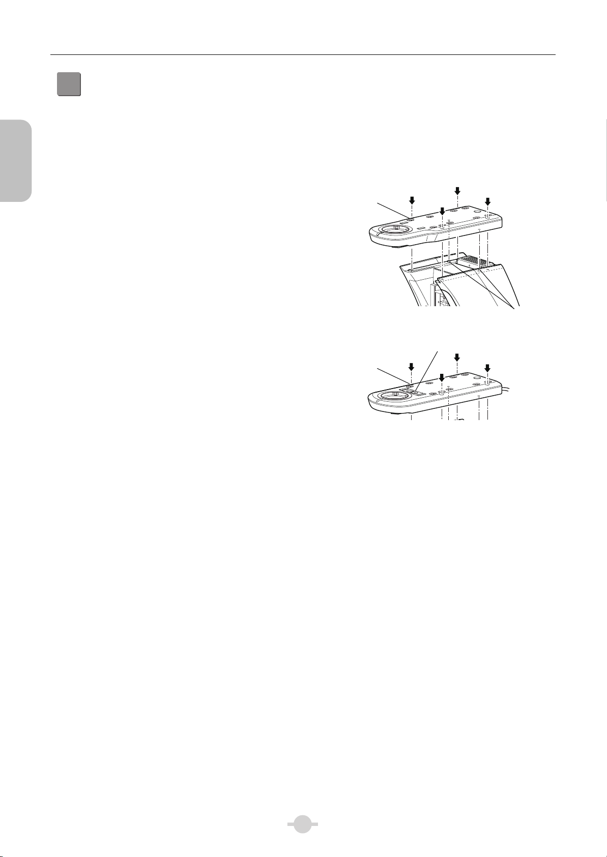
Attach the standard arm/contact arm.
5
The attachment procedure is the same for standard arm
and contact arm. To use the motorized accessories,
attach the contact arm. The contact arm has a contact.
When attaching a motorized device on the arm, remove
the contact cover beforehand.
Tool: Hex wrench (4 mm across flats)
(1) Place the arm while aligning it with the two
positioning pins on the main body and tighten the
four fixing screws.
(2) When using contact arm, connect the cable from the
CONTACT ARM1 connector to the CONTACT ARM1
connector on the control box B.
(3) Connect the cable from the CONTACT ARM2
connector to the CONTACT ARM2 connector on the
control box B.
rm fixing screw
rm fixing screw
(Standard arm)
Contact cover
Positioning pin
(Contact arm)
Attaching the arm
6
Chapter 1 Assembly
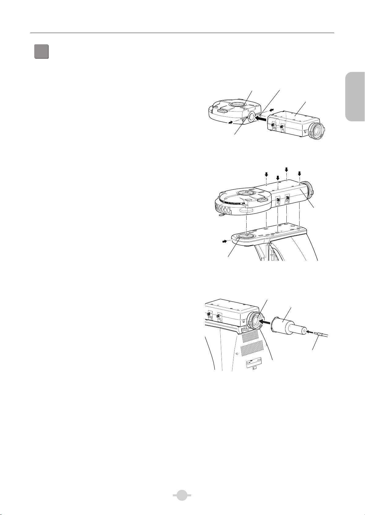
Attach the epi-fluorescence cube turret and epi-fluorescence attachment (required for
6
epi-fluorescence microscopy).
Tool: Hex driver (2 mm across flats)
Hex wrench (3 mm across flats)
First, connect the epi-fluorescence cube turret and
epi-fluorescence attachment and then attach them on the
microscope arm.
(1) Insert the positioning pin of the epi-fluorescence
attachment while aligning it with the positioning hole
on the epi-fluorescence cube turret side, and then
tighten the connection fixing screws (x2) on the
epi-fluorescence cube turret with a hex driver.
(2) When using a motorized or intelligent
epi-fluorescence cube turret, remove the contact
cover on the contact arm beforehand.
(Contact cover is not removed for manual
epi-fluorescence cube turret.)
(3) Loosen the fixing screw on the front of the arm using
a hex driver so that the tip of the screw does not
protrude into the connecting section.
(4) Align the round dovetail and convex contact on the
bottom of the epi-fluorescence cube turret with the
round dovetail and concave contact of the arm and
slide the entire mounted attachment to the rear.
(There is no concave contact in manual
epi-fluorescence cube turret.)
(5) Tighten the fixing screw loosened in step (3).
(6) Tighten the four fixing screws on top of the
epi-fluorescence attachment.
(7) Attach the HG adapter to the bayonet mount at the
rear of the epi-fluorescence attachment and connect
the HG precentered fiber illuminator. (See the
instruction manual provided with the HG
precentered fiber illuminator.)
Epi-fluorescence
cube turret
Positioning hole
Epi-fluorescence
attachment
F. STOP
A. STOP
EX. ADJ
Connection fixing screw
Connecting epi-fluorescence cube turret
and epi-fluorescence attachment
A. STOP
1
2
3
4
2
5
6
F. STOP
EX. ADJ
Fixing screw
Attaching and fixing epi-fluorescence cube turret
and epi-fluorescence attachment set
Bayonet mount
HG adapter
F. STOP
A. STOP
EX. ADJ
Assembly
Epi-fluorescence
attachment
fixing screw
7
MODEL ECLIPSE Ni-U
920001
100–240V~
MADE IN JAPAN
1.7A
NIKON CORPORATION
50/60Hz
TOKYO, JAPAN
This device complies with Part 15 of the FCC Rules. Operation is subject to the following two conditions:
(1) this device may not cause harmful interference, and
(2) this device must accept any interference received, including interference that may cause undesired operation.
This Class A digital apparatus complies with Canadian ICES-003.
INSPECTION
Cet appareil numérique de la classe A est confirme à la norme NMB-003 du Canada.
EQUIPMENT
4N75
Attaching the HG adapter
HG fiber
Assembly
A
A
Chapter 1 Assembly
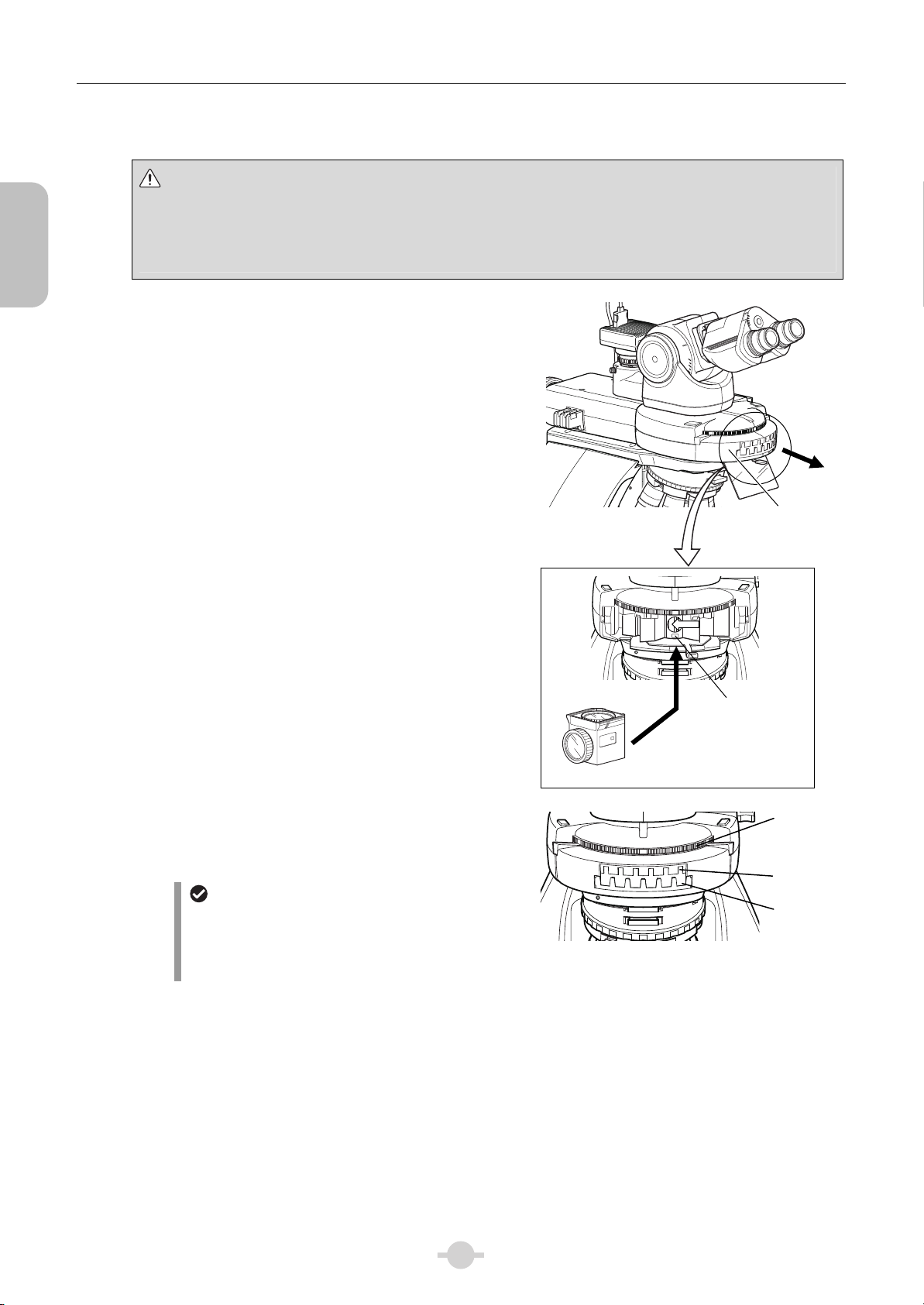
■ Attaching a filter cube
Precautions for attaching and removing the cube
• Be sure to check that the light source is turned off before attaching or removing the cube.
• Be sure to check that the power switch for microscope main body is turned off and then attach the cube by
rotating the cube switchover turret. Also for the motorized epi-fluorescence cube turret, attach it by manually
rotating the inside turret.
(1) Pull out the filter cube replacement cover on the
front of the epi-fluorescence cube turret to remove it.
(2) Attach the filter cube to the slot.
(3) Insert the filter cube nameplate into the slot cover
window.
ND4
ND8
Insert into the same address window as the address
shown inside the slot.
ND16
1
6
5
4
3
2
1
(4) Turn the cube switchover turret to attach the filter
cubes in the remaining slots and also insert the
nameplates.
For bright-field microscopy
For bright-field microscopy, be sure to make the
address 1 empty.
For motorized/intelligent epi-fluorescence cube
turret, only address 1 can be set to [OPEN].
(5) Restore the slot cover back to its original position.
1
UV-2A
EX 330-380
DM 400
BA 420
A
λ
6
Attaching a filter cube
5
6
2
5
A
Filter cube
2
A
λ
1
3
ddress
indication
Filter cube
replacement
slot cover
Cube
switchover
turret
ddress
indication
Nameplate
window
8
 Loading...