

Nikon Eclipse Ni-E Instruction Manual

Upright Motorized Microscope
M572 E 11.8.NF.1 (1/2)
*M572EN01*
Notes on Handling
the Product
Components
Microscopy
Safety Precautions
Before
(Focusing Nosepiece System)
Instruction Manual
Operation
Operation
Flowchart
Microscopy
IR-DIC
Epi-fluorescence
Microscopy
Operations
Individual


Introduction
Introduction
Thank you for purchasing a Nikon product.
This instruction manual is written for users of the Nikon ECLIPSE Ni-E (Focusing Nosepiece System) microscope. To
ensure correct usage, read this manual carefully before operating this product.
● No part of this manual may be reproduced or transmitted in any form without prior written permission from Nikon.
● The contents of this manual are subject to change without notice.
● The equipment described in this manual may differ from the actual product in its appearance.
● Although every effort has been made to ensure the accuracy of this manual, errors or inconsistencies may remain. If
you note any points that are unclear or incorrect, please contact your nearest Nikon representative.
● Some of the equipment described in this manual may not be included in the set you have purchased.
● If you intend to use any other equipment with this product, read the manual for that equipment too.
● If this equipment is used in a manner not specified by the manufacturer, the protection provided by the equipment may
be impaired.
● Training: This product can be used without special training, provided that this manual is read thoroughly before use. Kindly
contact your nearest Nikon representative if you have any questions, find any errors, or wish to provide us with your
opinion.
i
Introduction
Contents of the Manual
The instruction manual for ECLIPSE Ni-E (Focusing Nosepiece System) is provided in two volumes.
Operation (This manual)
Safety Precautions
Components
Microscopy Operations
Before Microscopy
Operation Flowchart
IR-DIC (Infrared Ray Differential Interference
Contrast) Microscopy Procedure
Epi-fluorescence Microscopy Procedure
Individual Operations
Symbols Used in This Manual
The following symbols are used in this manual.
Symbols for Safety
WARNING
CAUTION
Other Symbols
Indicates information you should note or comply with to prevent defects or malfunction of this product.
Indicates information you should be aware of in using this product, as well as other useful information.
Highlights important information that should be noted for safety. Read “Safety Precautions” for details.
Assembly/Maintenance
Assembly
Troubleshooting
Maintenance and Storage
Specifications
Before reading the “Assembly/Maintenance” manual,
read the “Safety Precautions” in the “Operation”
manual.
ii

Summary of Contents
Summary of Contents
Introduction
Contents of the Manual
Symbols Used in This Manual
(See the next page for detailed contents.)
Safety Precautions
Notes on Handling the Product
Components
(System Configuration and Controls)
Before Microscopy
(Information Setting for Motorized Operation)
Safety Precautions
Notes on Handling
the Product
Components
Microscopy
Before
Operation Flowchart
IR-DIC (Infrared Ray Differential
Operation
Flowchart
Microscopy
IR-DIC
Interference Contrast) Microscopy
Procedure
Epi-fluorescence Microscopy
Individual Operations
(Display Panel, Operation Buttons, Instructions for Each Part/
Device, Image Capture)
Microscopy
Operations
Epi-fluorescence
Individual
iii

Contents
Contents
Introduction .........................................................................................................................i
Contents of the Manual ....................................................................................................ii
Symbols Used in This Manual..........................................................................................ii
Summary of Contents ....................................................................................................... iii
Safety Precautions............................................................................................................ vi
WARNING and CAUTION Symbols................................................................................vi
Meaning of Symbols Used on the Product......................................................................vi
WARNING ................................................................................................................ vii
CAUTION ..................................................................................................................ix
Notes on Handling the Product......................................................................................... xi
Components............................................................................................. 1
1 Ni-E Focusing Nosepiece System Basic Configuration ............................................2
1.1 Components ....................................................................................................... 2
1.2 Controls .............................................................................................................. 3
1.3 Operation Buttons .............................................................................................. 4
1.4 Connectors ......................................................................................................... 5
Microscopy Operations........................................................................... 7
1 Before Microscopy ....................................................................................................8
2 Operation Flowchart................................................................................................10
3 IR-DIC (Infrared Ray Differential Interference Contrast) Microscopy Procedure ....12
4 Epi-fluorescence Microscopy Procedure.................................................................29
Individual Operations ............................................................................ 41
1 Display Panel Details ..............................................................................................42
2 Using Operation Buttons on Ni-E ............................................................................45
2.1 Front Operation Button..................................................................................... 45
2.2 Right Operation Button..................................................................................... 46
2.3 Left Operation Button ....................................................................................... 47
3 Adjusting the Brightness of a Diascopic Image.......................................................48
3.1 Adjustment by Lamp Voltage ........................................................................... 48
3.2 Adjustment with ND Filters............................................................................... 49
4 Focusing on the Sample (Vertical Objective Movement) ........................................50
4.1 Proper Focusing Procedure ............................................................................. 50
4.2 Focus Knobs on the Main Body ....................................................................... 51
4.3 Resetting the Z-axis Coordinate....................................................................... 52
4.4 Refocusing ....................................................................................................... 53
5 Bringing the Target into the Optical Path (Horizontal Stage Movement) .................54
5.1 Standard Stage Operation ................................................................................ 54
5.2 Operating the Motorized XY Stage................................................................... 55
6 Adjusting the Diopter...............................................................................................56
7 Focusing and Centering the Condenser .................................................................57
8 Adjusting the Aperture Diaphragm ..........................................................................58
9 Using the Condenser ..............................................................................................59
iv

Contents
10 Adjusting the Field Diaphragm ................................................................................61
11 Operating the Nosepiece (objective operation).......................................................62
11.1 Objective Vertical Movement Lever (objective switching, dipping) .................. 62
11.2 Parfocal Correction of Objective ...................................................................... 63
11.3 Centering the Objective.................................................................................... 64
11.4 Inserting/Removing the DIC Slider................................................................... 64
11.5 Single nosepiece .............................................................................................. 64
12 Using the Polarizer Turret .......................................................................................65
13 Switching the Optical Path of the Tube ...................................................................65
14 Adjusting the Binocular Section ..............................................................................66
15 Water Immersion.....................................................................................................66
16 Differential Interference Contrast Microscopy .........................................................67
16.1 Tips for Differential Interference Contrast Microscopy..................................... 67
16.2 Using Optical Elements.................................................................................... 68
17 Epi-fluorescence Microscopy .................................................................................. 69
17.1 Epi-fluorescence Cube Turret Operation (Switching Excitation Methods)....... 69
17.2 Selecting Filters................................................................................................ 71
17.3 Protecting the Sample and Preventing It from Decoloration
(Using the Shutter) ........................................................................................... 73
17.4 Adjusting the Brightness of the Fluorescent Image
(Using ND Filters and the Aperture Diaphragm) .............................................. 75
17.5 Restricting the Illumination to the Area of the Sample Being Viewed
(Centering and Adjusting the Field Diaphragm)............................................... 76
17.6 Changing the Waveform Characteristics of the Excitation Light
(D-FB Excitation Balancer)............................................................................... 77
17.7 Other Notes on Epi-fluorescence Microscopy.................................................. 78
18 Useful Functions .....................................................................................................79
18.1 Mode Function.................................................................................................. 79
18.2 Interlocking Function ........................................................................................ 82
19 Capturing Images....................................................................................................83
20 Operation on DS-L3 ................................................................................................87
20.1 Setting Up the Microscope ............................................................................... 87
20.2 Microscope Control ........................................................................................ 100
v
Safety Precautions
Safety Precautions
To ensure correct and safe operation, read this manual before using this product.
Safety Precautions
Notes on Handling
the Product
WARNING and CAUTION Symbols
Although this product is designed and manufactured to be completely safe during use, incorrect usage or failure to follow
the safety instructions provided may cause personal injury or property damage. To ensure correct usage, read this manual
carefully before using this product. Do not discard this manual and keep it handy for easy reference.
Safety instructions in this manual are marked with the following symbols to indicate their importance. For your safety,
always follow the instructions marked with these symbols.
Symbol Description
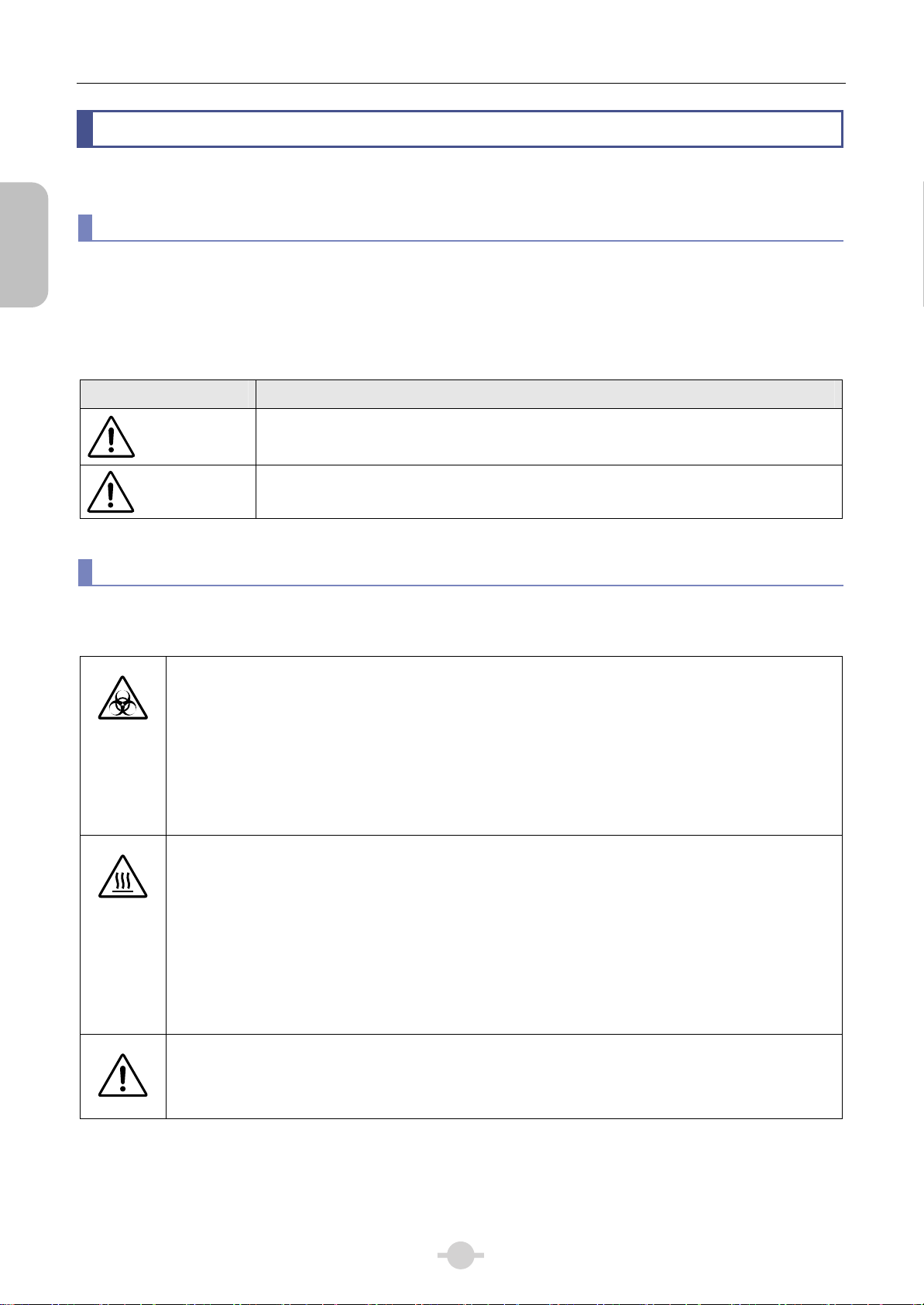
WARNING
When appearing on this product, the symbols below indicate the need for caution at all times during use. Read the
relevant instructions in this manual before attempting to use or adjust any part to which the symbol has been affixed.
CAUTION
Meaning of Symbols Used on the Product
Biohazard
This symbol is affixed to the front of the stand of this product, to call your attention to the following:
● WARNING: Using this product may constitute a biohazard risk if a sample comes into contact with this
product.
● To avoid biohazard contamination, do not touch the contaminated portion with bare hands.
● Decontaminate the contaminated part in accordance with the standard procedure specified for your
laboratory.
Precautions against heat
This symbol is affixed to the lamphouse to call your attention to the following:
● During and immediately after a period of illumination, the lamp and surrounding areas (including the
lamphouse) are very hot.
● Risk of burns. Do not touch the lamp or surrounding areas during or immediately after a period of
illumination.
● Make sure the lamp and surrounding areas have cooled sufficiently (which may take approx. 30
minutes) before attempting to replace the lamp.
Disregarding instructions marked with this symbol may lead to serious injury or death.
Disregarding instructions marked with this symbol may lead to injury or property damage.
Precautions against heat
This symbol is affixed to the top of the arm (both standard and contact), but “Precautions against heat” is
not required when using in combination with Ni-E Microscope.
vi

Safety Precautions
1 Do not disassemble.
Disassembling this product may result in electric
shock or malfunction. Malfunction and damage
due to disassembling or modification are
unwarranted.
Do not disassemble parts other than those
described in this manual. If you experience
problems with this product, contact your nearest
Nikon representative.
2 Read the instruction manuals carefully.
To ensure safety, thoroughly read this manual and
the manuals for other equipment to be used with
this product. Particularly, all warnings and
cautions given at the beginning of each manual
must be observed.
Safety is a top design priority for Nikon products.
Safety is ensured as long as the user observes all
of the warnings and cautions given in the
manuals, and uses the system only for its
intended purpose. However, failure to heed the
warnings and cautions given in the manuals,
subjecting the system to shock or impact, or
attempting to disassemble the system may result
in unexpected accidents and injury.
Product with NI-FLEI epi-fluorescence
attachment:
The light source used for Epi-fluorescence
microscopy (HG Precentered Fiber Illuminator)
requires special care during handling because of
its characteristics. Be sure to refer to the manual
for the light source being used.
WARNING
4 Heat from the illuminator
During and immediately after a period of
illumination, the lamp and surrounding areas
(including the lamphouse) are very hot.
● Do not touch the lamp or surrounding areas
during or immediately after a period of
illumination. There is a risk of burn if you touch
the hot area.
● Always attach the lamphouse cover when using
this product.
● Make sure the lamp and surrounding areas
have cooled sufficiently (which may take
approx. 30 minutes) before attempting to
replace the lamp.
● To avoid the risk of fire, do not place fabric,
paper or highly flammable volatile materials
such as gasoline, petroleum benzine, paint
thinner, or alcohol near the lamphouse while
the lamp is lit or for a period of approximately
thirty minutes after the lamp is turned off.
Safety Precautions
Notes on Handling
the Product
3 Notes on the power cord
Be sure to use the specified power cord. Use of
other power cords may result in malfunction or
fire. This product is classified as having Class I
protection against electric shock. Make sure this
product is connected to an appropriate protective
earth terminal.
See Chapter 4 “2. Performance Properties” in the
“Assembly/Maintenance” instruction manual for
designated power cords.
● To prevent electric shock, always turn off the
power switch (press to the “O” position) for the
microscope before connecting or disconnecting
the power cord.
vii

Safety Precautions
WARNING
Safety Precautions
Notes on Handling
the Product
5 Hazards of mercury lamps
(when using the NI-FLEI Epi-fluorescence
attachment)
The light source used with the epi-fluorescence
attachment (HG Precentered Fiber Illuminator)
requires special care during handling because of
its characteristics. For safe and correct use of this
system, carefully read the warnings below. Keep
in mind all potential hazards. Additionally, carefully
read the manual for the illuminator and the manual
from the lamp manufacturer (if provided), then
follow the instructions given therein. Failure to
heed the warnings and cautions given in the
manuals, subjecting the system to shock or
impact, or attempting to disassemble the system
may result in unexpected accidents and injury.
● Ultraviolet light
When lit, mercury lamps radiate ultraviolet light
that can damage the eyes and skin. Direct
viewing of the light may result in blindness.
When changing filter cubes, always turn off the
light source of the Epi-fluorescence
attachment. Leaving the lamp turned on during
filter cube replacement may result in ultraviolet
exposure.
Leave the D/UV slider of the D-ES EPI ND
slider within the optical path. Removing the
D/UV slider from the optical path will cause
your eyes to become exposed to ultraviolet
light.
● High-pressure gas
The lamps contain sealed gas under very high
pressure. And the pressure increases when the
lamp is on. If the lamp is scratched,
contaminated, subjected to high external
pressure or physical impact, or used beyond its
service life, the sealed gas may leak or the
lamp may burst, resulting in gas inhalation,
injury from glass, or other accidents.
● Heat
When the lamp is lit, the lamp and surroundings
will become extremely hot. Do not touch the
lamp with bare hands or place flammable
materials near the lamp. Failure to comply may
result in burns or fire.
6 Hazardous sample handling
This product is intended primarily for microscopic
observations and image capture of samples
(biological tissue, brain slice, etc.) in chambers.
Check to determine whether a sample is
hazardous before handling. If sample is
hazardous, handle it according to the standard
procedure specified for your laboratory. If the
sample is potentially infectious, wear rubber
gloves and avoid directly touching samples. If
such a sample is spilled onto this product, the
portion must be decontaminated in a safety
manner. Consult your safety supervisor or safety
standard of your facility.
● Designated lamp
Be sure to use the designated lamp. Using
other types of lamps may result in accidents,
including bursting of the lamp.
viii

Safety Precautions
1 Power shutdown
To prevent electric shock and/or malfunction,
always turn off the power switch(es) for this product
and the peripheral devices (press to the “O”
position) and unplug the power cord from the wall
outlet before assembling this product, connecting
or disconnecting cables, replacing lamps, or
cleaning this microscope and the objective.
2 Lamp replacement precautions
● To avoid burns, wait at least 30 minutes after
the lamp is turned off to give it sufficient time to
cool. To avoid electric shock or malfunctions,
never attempt to replace the lamp without first
turning off the power switches for this product
and the peripheral devices (press to the “O”
position) and unplugging the power cord from
the wall outlet.
● After replacing the lamp, make sure to reattach
the lamphouse cover. Do not use the product
without the lamphouse cover attached.
● Do not break used lamps. It should be disposed
of as industrial waste, in accordance with local
regulations and rules.
3 Designated lamp
Using power supplied from control box A to the
main body, halogen lamps of up to 12V-100W can
be lit. Always use the specified lamp and
lamphouse. Using unspecified products may
cause malfunctions.
Lamphouse model
● Specified lamp:
12V 100W halogen lamp PHILIPS 7724 or
OSRAM HLX64623
● Specified lamphouse:
Nikon NI-LH or NI-IRLH precentered lamphouse
Optical fiber model
● Specified lamp:
12V 100W halogen lamp
● Specified illuminator:
Sumita Optical Glass’s halogen light source
optical fiber illuminator LS-DWL-N
CAUTION
4 Movement of motorized device
This product can be equipped with motorized
devices such as motorized epi-fluorescence cube
turret and motorized quadrocular tilting tube,
which can be controlled from remote controllers
and PCs.
To avoid unexpected injuries, note the following in
operating motorized devices.
● Before operation, check the state of the entire
microscope system to ensure safety when
operating the motorized devices.
● Keep your hands and fingers away from the
stage, components and sample on the stage to
avoid injuries during operation.
5 Avoid contact with water or chemical
solutions.
Never expose this product to water or chemical
solutions, and avoid using this product in
circumstances where there is risk of exposure to
water or chemical solutions. Exposure of electric
parts (such as the HG Precentered Fiber
Illuminator) to liquids may cause a short circuit,
resulting in malfunction or abnormal heating. If
water or a chemical solution is splashed onto this
product, immediately turn off the power switches
for this product and the peripheral devices (press
to the “O” position) and remove the power cord
from the receptacle. Then wipe off moisture with a
piece of dry cloth or something similar. If water or
a chemical solution enters this product, stop using
the product, and contact your nearest Nikon
representative.
6 Remove any covers from the product before
switching on.
Do not use this product while it is covered with a
piece of cloth, etc., as this will prevent heat
release and result in abnormal heat and create a
fire hazard. Do not cover this product with a piece
of cloth or similar while in use. The system
temperature will rise, resulting in a malfunction.
7 Notes on Laying Cables
During a period of illumination, the lamphouse is
very hot. Try to lay cables so that they do not
contact the lamphouse.
Safety Precautions
Notes on Handling
the Product
8 Do not place any object on top of the
product.
Do not place any object on top of this product.
ix

Safety Precautions
CAUTION
Safety Precautions
Notes on Handling
the Product
9 Cautions on assembling and installing the
product
● Take care to avoid pinching your fingers or
hands during product assembly and
installation.
● Scratches or fouling optical components (such
as lens and filters) with fingerprints, etc. will
degrade microscope images. Be careful to
avoid scratches or direct contact with the lens
and filters when assembling.
● The main body weighs approximately 11 kg.
This product is not designed to be portable.
When moving the microscope (i.e. to another
room within the facility), work in a team of at
least two persons, and firmly hold the base of
the product.
● Remove all attachments (if mounted) from the
microscope before moving the microscope.
● Do not place this product in a locker or cabinet.
10 Cautions on sustained observations
To relieve fatigue resulting from long observation
sessions, limit continuous observations to one
hour. Take at least 10 to 15 minutes breaks
between observation sessions. Adjust the layout
of other equipment used and the height of your
chair.
11 Cautions on use, transportation, and
storage
This product must be operated, transported, or
stored in accordance with the following conditions.
Installing this product in a hot, humid location may
result in the formation of mold or condensation on
lenses, impairing performance or causing
malfunctions.
● Operating conditions:
temperature: 0 to +40°C, humidity: 60% RH
max. (no condensation)
● Transporting/storage conditions:
temperature: -20 to +60°C, humidity: 90% RH
max. (no condensation)
See Chapter 3 “4 Transportation (Using Fastening
Position Mode Switch)” in the “Assembly/
Maintenance” instruction manual for fastening the
system during its transportation.
12 Cautions on the disposal of the product
To avoid biohazard risks, dispose of this product
as contaminated equipment in accordance with
the standard procedure specified for your facility.
x

Notes on Handling the Product
1 Handling the product carefully
This product is a precision instrument. Avoid
subjecting it to sudden impacts and shocks.
Even relatively minor impacts are capable of
affecting the precision of the objective.
2 Weak electromagnetic waves
This product emits weak electromagnetic waves. So
as to avoid degrading the performance of precision
electronic devices, do not install this product near
such devices. If TV or radio reception is affected,
move the TV or radio further from this product.
Notes on Handling the Product
● To avoid splashes, do not use this product near
water.
● Make sure the ambient temperature is 0 to
+ 40°C and humidity is 60% or less. When
transporting or storing this product, the ambient
temperature must be -20 to +60°C, with the
humidity at 90% RH max (with no condensation).
Installing this product in a hot, humid location
may result in the formation of mold or
condensation on lenses, impairing performance
or causing malfunctions.
● Do not place this product in a locker or cabinet.
Safety Precautions
Notes on Handling
the Product
3 Scratches, dirt, and foreign particles on the
lens
Scratches or fouling optical components (such as
lens and filters) with fingerprints, etc. will degrade
microscope images.
If these parts become dirty, clean them as described
in Chapter 3 “2.1 Cleaning Lenses” in the
“Assembly/Maintenance” instruction manual.
4 Installation location
This product is a precision instrument. Usage or
storage of this product in an inappropriate
environment may result in malfunction or a
degradation in precision. Consider the following
factors when selecting an installation location:
● Select a location free of vibration. Install this
product on a level surface.
● Install this product at least 10 cm away from
walls.
● Choose a location less exposed to hazards in the
event of collisions, earthquakes, or other
potential disasters. To keep this product from
falling, use a strong rope or other means if
necessary to secure it to the working desk or
other heavy, stable item. This product is provided
with a M6 screw hole on the right and left sides of
the recessed area at the lower back of the main
body.
● Select a layout that allows easy removal of the
power cord from the product’s AC inlet in the
event of an emergency.
● Do not use a desk mat or similar.
● Avoid locations exposed to direct sunlight,
locations immediately under room lights, and
other bright locations.
● Light from room lights just above this product may
enter the objective as extraneous light. If possible,
switch off the room lights directly above this
product when making observations.
● Select a location with minimal dust.
5 Handling a Focus Knob
● Never turn the focus knobs on the right and left
sides of the microscope in opposite directions at
the same time. Doing so may damage this
product.
6 Protect the ports from dust and extraneous
light
Always attach the supplied cap to any ports not in
use and slider slot while a tube, epi-fluorescence
cube turret or other devices are mounted. Otherwise,
extraneous light and dust may be trapped inside the
product.
7 Handling of filters (when using the
epi-fluorescence attachment)
● Excitation filters inside a filter cube are exposed
to strong light and degrade over time. Replace
them after the appropriate number of hours of
use.
● Filter characteristics may alter if the filter is
exposed to high humidity. To prevent changes or
degradation of filter characteristics, avoid using
or storing the filters under conditions of high
humidity or high temperature. Avoid subjecting
filters to rapid temperature changes. When a
filter is not in use, store in a desiccator or
hermetically sealed container with a drying
agent.
● Especially the filters in the nine types of filter
cubes listed below offer sharp, high-resolution
waveform characteristics superior to normal
filters. However, due to their sophisticated
coatings, they must be handled with special care.
Take care to avoid abrasion from cleaning.
Follow the description in Chapter 3 “2.1 Cleaning
Lenses” in the “Assembly/Maintenance”
instruction manual.
Single-band filter cubes: DAPI, FITC, TxRed,
GFP
Multi-band filter cubes: F-R, F-T, D-F, D-F-R,
D-F-T
xi

Notes on Handling the Product
8 Motorized devices
When using motorized devices, do not force the
motorized devices to move/stop by hand.
Safety Precautions
Notes on Handling
the Product
9 Vibration during motorized operation
While the product is designed to minimize the
amount of vibration during motorized operation,
note that there still may be some effect on the
microscopy results.
10 Unpacking and unlocking
1) Check the package contents.
● ECLIPSE Ni-E x1
● Hex driver X3
Hex wrench X2
● Toolbox X1
● Accessory sticker X2 types
(A blinder for the mounting hole for accessory
not in use on the top of the arm and
nameplate for an additional ND filter to the
ND filter cassette)
2) Before turning on the power, remove the fixing
screw from the front of the elevating section.
(See Chapter 1 “3 Assembly Method - 2
Unfasten the elevating section” in the
“Assembly/Maintenance” instruction manual for
details.)
3) Do not dispose of the packing materials. They
will be reused for transportation.
xii

1
Chapter
1
Components
This chapter contains the system configuration diagram of the focusing nosepiece system with name of components and
controls.
Figures are examples of the basic system configuration. Devices other than those shown in the figures are also available.
For a list of components used for ECLIPSE Ni-E microscope (focusing nosepiece system), refer to Chapter 1, “2
Components List” in the separately provided “Assembly/Maintenance” instruction manual.
Components
1
Chapter 1 Components
(
)
r
r
)
A
(
)
r
r
1
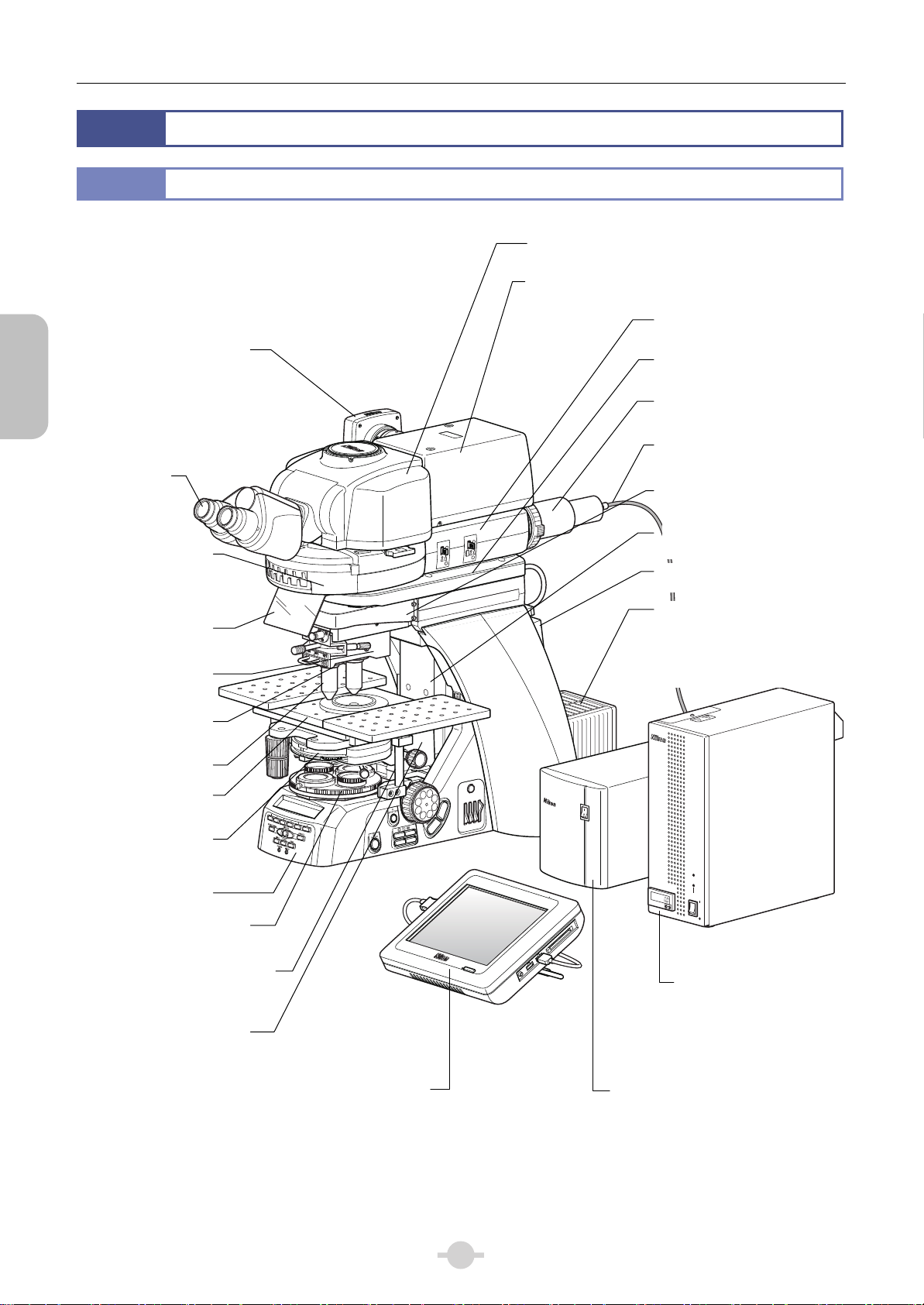
Ni-E Focusing Nosepiece System Basic Configuration
1.1
Components
Components
Camera head
Motorized quadrocular tilting tube
(Model: NI-TT-E)
Motorized DSC zooming port for
quadrocular tube (Model: NI-RPZ-E)
Epi-fluorescence attachment
(Model: NI-FLEI)
Contact arm
(Model: NIE-CAM)
HG adapter
(Model: C-HGFIB)
HG fiber
(Model: C-HGFIF 15/30)
Eyepiece
70
60
50
rm spacer 49 mm
(model: NI-AMSS)
Motorized
epi-fluorescence
cube turret
(Model: NI-FLT6-E)
Light shielding
Sliding nosepiece
(Model: FN-S2N)
DIC prism
Objective
Stage
(Model: FN-3PS2)
LWD condense
(Model: FN-C LWD)
Ni-E main body
Polarizer turret
(Model: NI-PT)
FN1 stage adapte
(Model: NI-3PSA)
(Also on the left side)
Substage for focusing
Model: NI-SSF
plate
slide
nosepiece
2
3
4
5
6
JAPAN
FN-S2N
DS camera control unit
(Model: DS-L3)
(See instruction manual fo
DS-L3
A. STOP
F. STOP
EX. ADJ
Focusing nosepiece sub arm
(Model: NI-FNA)
Connector box
Model: NIE-CB
Precentered lamphouse
(12V 100W) (Model: NI-LH or
NI-IRLH)
Halogen lamp (100W)
(Model: PHILIPS 7724 or
OSRAM HLX64623)
INTENSILIGHT
C
-
HGFIE
NCB
ND
ND
11
32
8
OUT
IN
LAMP
RUN TIME hrs.
POWER
Motorized HG precentered
fiber illuminator
(Model: C-HGFIE)
(→See HG Precentered
Fiber Illuminator
instruction manual)
Control Box A
(Model: NI-CTLA)
2
Chapter 1 Components
r
A
A
r
A
p
r
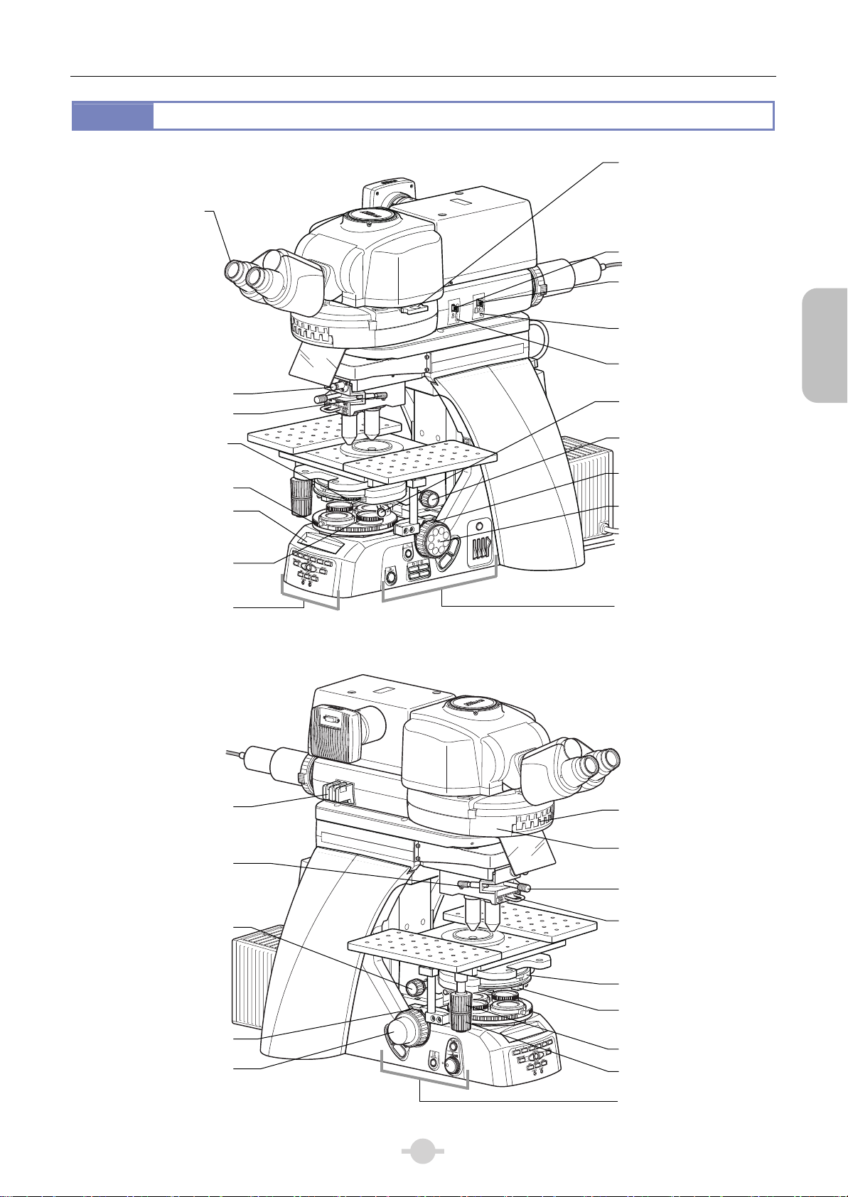
1.2
Controls
Diopter
adjustment
ring
70
60
50
FL/DIC analyzer
slider NI-FA
(used for epi-fluorescence/
differential interference
contrast microscopy)
Field diaphragm leve
Slide click release button
Parfocal correction knob
(for rear objective)
Rotation ring of
diaphragm for the
diagonal illumination
Polarizer turret
Display panel
(See Chapter 3, “1 Display
Panel Details”.)
Polarizer rotation
knurled ring
Front operation buttons
(See “1.3 Operation
Buttons” on the next page.)
A. STOP
F. STOP
2
3
4
5
6
EX. ADJ
lever
perture diaphragm
Components
centering screws
Field diaphragm
perture diaphragm
JAPAN
FN-S2N
centering screws
Condenser centering
screw
Condenser focus knob
Coarse focus knob
Fine focus knob
NCB
ND
ND
11
32
8
OUT
IN
Right operation buttons
(See “1.3 Operation
Buttons” on the next
page.)
ND filter slide
Parfocal correction knob
(for front objective)
Condenser focus knob
Coarse focus knob
Fine focus knob
70
60
50
ND4
ND8
ND16
5
4
3
2
1
Filter cube name plate
window
Filter cube
lacement cove
re
Objective vertical
movement lever
Sliding nosepiece grip
Condenser turret
perture diaphragm
lever
Stage Y knob
Stage X knob
Left operation buttons
(See “1.3 Operation
Buttons” on the next page)
3

Chapter 1 Components
y
1.3
Operation Buttons
FUNCTION buttons
(Factory settings:
Button 1, 2: Condenser CCW, CW
rotations
Button 3, 4: Excitation filter wheel
CCW, CW rotations
Display panel
brightness control
Button 5, 6: Barrier filter wheel
CCW, CW rotations)
button
Components
DISPLAY Previous button
DISPLAY switch button
BINO optical path button
Power LED
FRONT optical path
button
Z-RESET button
DISPLAY Next button
REAR optical path button
Sleep LED
Ni-E Front Operation Buttons
FL SHUTTER button
(Factory setting: Shutter built into
first epi-fluorescence cube turret)
ND filter IN/OUT switch
CAPTURE button
(Factory setting: Camera
directly controlled b
DS-L3 connected to USB
connector)
DIA field diaphragm button
DIA aperture diaphragm button
ND8ND
NCB
32
11
OUT
IN
FL CUBE CCW rotation button
(Factory setting: First epi-fluorescence cube
turret)
FL CUBE CW rotation button
(Factory setting: First epi-fluorescence cube turret)
Ni-E Right Operation Buttons
OBJ CW rotation button
(Factory setting: Nosepiece)
Dia-illumination
ON/OFF switch
OBJ CCW rotation button
(Factory setting: Nosepiece)
Dia-illumination brightness control
knob
Escape button
Ni-E Left Operation Buttons
Changing operation button assignments
Buttons indicated with “(Factory setting: ...)” can be assigned to different functions.
There are some Ni-E focusing nosepiece systems with target devices that are not motorized at factory shipment.
(Example: nosepiece and condenser) Change the function assignment of buttons that are to control the nosepiece and
condenser.
Different functions can be assigned from the DS-L3 DS camera control unit. See Chapter 3, “20 Operation on DS-L3” “20.1 Setting Up the Microscope - (3) Configuring the Button Functions - (3-1) Ni-E microscope button”.
In the explanations of operations in this manual, functions of these buttons are assumed to be left as factory settings.
4
Chapter 1 Components
f
f
f
r
)
)
p
)
A
f
r
)
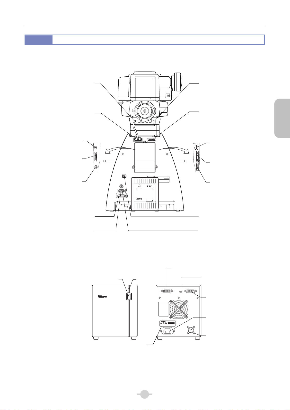
1.4
Connectors
(Connect to CONTACT ARM2 o
CONTACT ARM2
Ni-E main body)
CONTACT ARM2
(Connect to CONTACT ARM2 o
contact arm)
DSC2
(Connect to EXT.I/O o
DS-L3/U3)
ERGO/JOY
(Connect to ergo controlle
or
joystick controller)
ND
(Connect to the
motorized
ND filter wheel)
(Connect to Ni-E of control box A)
(Connect to motorized HG
precentered fibe
illuminator
BOX
HGFIE
DSC2
ERGO/JOY
ND
Power switch
USB
DSC1
HGFIE
BOX
Ni-E (Rear)
CONTACT ARM2
-High Temperature-
CAUTION!
Do not touch the lamphouse while the lamp is lit.
1.
The surface of the lamphouse becomes hot when the
lamp is on.
2.
Turn off the power and allow the lamp and lamohouse
to cool enough before replacing the lamp.
Wait for at least 30 minutes after turning off the
lamp.
3.
Use 12V100W HALOGEN lamp only.
HALOGEN 12V100W
JAPAN
Power LED
EPI SHUTTER
MODEL ECLIPSE Ni-E
NIKON CORPORATION
910001
TOKYO, JAPAN
This device complies with Part 15 of the FCC Rules. Operation is subject to the following two conditions:
(1) this device may not cause harmful interference, and
(2) this device must accept any interference received, including interference that may cause undesired operation.
This Class A digital apparatus complies with Canadian ICES-003.
Cet appareil numérique de la classe A est confirme à la norme NMB-003 du Canada.
NI-LH
952001
MADE IN JAPAN
Ni-E CONTACT
This device complies with Part
15 of the FCC Rules. Operation
is subject to the following
two conditions:
(1) this device may not cause
harmful interference, and
(2) this device must accept any
interference received,
including interference that
may cause undesired
operation.
This Class A digital apparatus
complies with Canadian ICES-003.
Cet appareil numérique de la
classe A est confirme à la
norme NMB-003 du Canada.
100-240V~ 5A 50/60Hz
CONTACT ARM1
(Connect to CONTACT ARM1 o
control box A)
EPI SHUTTER
(Connect to EPI motorized
shutter)
EX
STAGE
DIA SHUTTER
USB
(Connect to DS-L3 or PC)
DSC1
(Connect to EXT.I/O of
DS-L3/U3)
Ni-E (Connect to Ni-E BOX)
Fastening position mode switch
(ON: fastening position mode,
OFF: normal mode)
MODEL NI-CTLA
540001
MADE IN JAPAN
OFF ON
FASTENING
POSITION SW
ARM1
LAMP
Components
EX
(Connect to motorized
excitation
filter wheel
STAGE
(Connect to
MICROSCOPE for the
motorized
DIA SHUTTER
(Connect to
DIA motorized shutter)
CONTACT ARM1
(Connect to CONTACT ARM1
of contact arm
C inlet
(Connected to AC power
using a power cord)
Input voltage label
LAMP
(Connect to dia-illumination
house
lam
Control Box A (Front/Rear)
5

Chapter 1 Components
Components
6

2
Chapter
2
Microscopy Operations
This chapter describes the following microscopy operation procedures.
In the examples, the basic system configurations shown in the previous chapter are used.
Microscopy
Operations
Operation procedure 1: IR-DIC (Infrared Ray Differential Interference Contrast) microscopy
Operation procedure 2: Epi-fluorescence microscopy (including cautions on switching between or in conjunction with
IR-DIC microscopy)
The procedures described herein assume that all required components are attached to the microscope, with all necessary
cables properly connected, and that information registration for motorized operation has been completed. The functions of
microscope’s control buttons are assumed to be set to default (factory setting).
When using the microscope for the first time or changing the motorized settings from the factory default before use, see “1
Before Microscopy” in this chapter and Chapter 3, “20 Operation on DS-L3” - “20.1 Setting Up the Microscope” before the
microscopy operation.
If you have yet to complete the assembly of the microscope, see Chapter 1, “3 Assembly Method” in the separately
provided “Assembly/Maintenance” instruction manual to complete the assembly.
7

Microscopy
Before
Chapter 2 Microscopy Operations
1
Information for motorized operation of the microscope has been set upon shipment. If you start using the microscope with the
motorized settings of factory default, turn ON the switch of the Control Box A after the assembly of the microscope to use.
However, information on optical elements such as optional filter cube are not set a factory shipment. It is useful to have the
device information configured before the use of the microscope.
You can change the factory default motorized setting information according to your needs.
Configure these settings on the [SETUP MENU] screen of the DS-L3 DS Camera Control Unit.
The table shown below summarizes the contents of the SETUP MENU. Make necessary settings accordingly. (The items
marked with "*" are not applicable to the focusing nosepiece system.)
See Chapter 3, “20 Operation on DS-L3” - “20.1 Setting Up the Microscope” in this document for the summary of the
setting operation.
See “DS-L3 Microscope Operation” Instruction Manual provided with DS-L3 for details on using DS-L3.
Objective*
(motorized nosepiece/intelligent nosepiece)
DIC module, PH module, etc.
(motorized universal condenser)
Filter cube
(motorized/intelligent filter cube on the 1st.
and 2nd. layers)
Excitation filter
(motorized excitation filter wheel)
Barrier filter
(motorized barrier filter wheel)
Destination camera to output signal from the
DSC connector
(Connector DSC1: Rear of the microscope)
(Connector DSC2: Connector box)
Motorized shutter connected to a SHUTTER
connector
(Connector EPI SHUTTER: Rear of the
microscope)
(Connector DIA SHUTTER: Connector box)
Ni-E microscope
Functions of six FUNCTION buttons
Ni-E microscope
Motorized shutter controlled with the FL
SHUTTER button
Ni-E microscope
Digital camera controlled with the CAPTURE
button
Ni-E microscope
Motorized device operable with the FL CUBE
CW/CCW button
Ni-E microscope
Motorized device operable with the OBJ
CW/CCW button
Ni-E microscope
Enabling/disabling operation buttons
Ergo controller
Functions of operation buttons
Before Microscopy
Microscope Setup from DS-L3
Setting Default setting Where to see in this manual (DS-L3 for details)
[COMPONENTS] →Chapter 3 23.1-(1)
None
Address 1: Set to OPEN.
Other addresses: None
None
None
Address 1: Set to OPEN.
Other addresses: None
[CONNECTION] →Chapter 3 23.1-(2)
Not connected
EPI SHUTTER:
Motorized shutter for the
epi-illumination
DIA SHUTTER:
DIA motorized shutter for
the dia-illumination
[BUTTON FUNC] →Chapter 3 23.1-(3)
FUNCTION button
1, 2: Motorized universal
condenser
Reverse/forward rotation
3, 4: Motorized excitation filter
wheel
Reverse/forward rotation
5, 6: Motorized barrier filter
wheel
Reverse/forward rotation
Shutter built in the
motorized epi-fluorescence
cube turret on the 1st. layer
Camera controlled directly
with DS-L3 connected to a
USB connector
Motorized epi-fluorescence
cube turret on 1st layer
Motorized nosepiece
Enabled
Configured
(See Chapter 3 “20 Using
the Ergo Controller” in this
manual.)
→DS-L3 Chapter 6 “2.1 Configuring the
Objective Information”
→DS-L3 Chapter 6 “2.2 Configuring the
Condenser Module Information”
→DS-L3 Chapter 6 “2.3 Configuring the Filter
Cube Information”
→DS-L3 Chapter 6 “2.4 Configuring the
Excitation Filter/Barrier Filter Information”
→DS-L3 Chapter 6 “2.4 Configuring the
Excitation Filter/Barrier Filter Information”
→DS-L3 Chapter 6 “3.1 Configuring the
Connection of Digital Camera”
→DS-L3 Chapter 6 “3.2 Configuring the
Connection of Motorized Shutter”
→DS-L3 Chapter 6 “4.2.1 Setting the Function of
the Function Buttons”
→DS-L3 Chapter 6 “4.2.2 Changing the
Motorized Shutter Operated with the FL
SHUTTER Button”
→DS-L3 Chapter 6 “4.2.3 Changing the Digital
Camera Operated with the Microscope’s
CAPTURE Button”
→DS-L3 Chapter 6 “4.2.4 Changing the
Motorized Device to be Operated with
CW/CCW Button”
→DS-L3 Chapter 6 “4.2.4 Changing the
Motorized Device to be Operated with
CW/CCW Button”
→DS-L3 Chapter 6 “4.2.5 Enabling/Disabling the
Button Operation”
→DS-L3 Chapter 6 “4.3 Configuring the Function
of the Ergo Controller Buttons”
8

Chapter 2 Microscopy Operations
Setting Default setting Where to see in this manual (DS-L3 for details)
DS-L3
Buttons displayed on the [MICROSCOPE
CONTROL] screen
DS-L3
Buttons displayed on the [CAM-MIC
CONTROL] screen
DS-L3
Hiding the [SLEEP] button on the screen
[MOVEMENT] →Chapter 3 23.1-(4)
Interlocked operation of the objective* OFF
Interlocked operation when switching zoom
magnification
Interlocking operations with the switching of
the optical path
*
Automatic operation interlocked with capture
button operation
Retracting amount of the elevating section Software limit position
Rotation stop of the nosepiece depending on
the position of the elevating section
*
Reverse rotation stop of the nosepiece* No rotation stop
Toggle rotation of the nosepiece* Toggle operation OFF
[MODE] (Registration of motorized unit for MODE) →Chapter 3 23.1-(5)
Registering a motorized unit with mode (8
modes)
[UTILITY] →Chapter 3 23.1-(6)
Setting the display pattern of the Ni-E front
display panel
Enabling/disabling the operation of the
elevating section
Setting the XYZ position software limit
Buzzer that sounds when you press operation
buttons
[MAINTENANCE] →Chapter 3 23.1-(7)
Movement speed of the epi-fluorescence
cube turret
Resetting data ...
Display of the program version ...
Configured
(See DS-L3 Chapter 2 “3.1
[MICROSCOPE CONTROL]
Screen (Ni-E)”.)
Configured
(See DS-L3 Chapter 2 “3.2
[CAM-MIC CONTROL]
Screen (Ni-E)”.)
Hidden
*
OFF
OFF
OFF
No rotation stop
Not registered
Pattern 1
(See Chapter 3 “1 Display
Panel Details”.)
Enabled
Z-axis: -2000.000 μm
X-axis max. value:
34000.000 μm
X-axis min. value:
-34000.000 μm
Y-axis max. value:
27000.000 μm
Y-axis min. value:
-27000.000 μm
When pressing the button
of the Ni-E main body:
Buzzer sounds
When pressing the button
of the ergo controller:
No buzzer sound
Set to “High Speed”
→DS-L3 Chapter 6 “4.1.1 Selecting the Buttons
to be Displayed”
→DS-L3 Chapter 6 “4.1.1 Selecting the Buttons
to be Displayed”
→DS-L3 Chapter 6 “4.1.2 Showing/Hiding the
[SLEEP] Button”
→DS-L3 Chapter 6
“5.1.1 Configuring the Interlocked Operation
with Switching of Objectives”
“5.1.2 Changing the Initial Value of the
[INTELLIGENT]”
“5.1.3 Automatically Switching the Movement
Speed of the Microscope’s Elevating Section
and Motorized Stage”
“5.1.4 Configuring the Parfocal Correction
Function (Auto Link Focus)”
→DS-L3 Chapter 6 “5.1.5 Configuring the
Interlocked Operation with Switching of Zoom
Magnification”
→DS-L3 Chapter 6 “5.1.6 Configuring the
Interlocked Operation with Switching of Optical
Path”
→DS-L3 Chapter 6 “5.1.7 Configuring the
Interlocked Operation with Capture Command
Sending or Trigger Signal Output”
→DS-L3 Chapter 6 “5.2 Setting the Retracting
Amount of the Elevating Section”
→DS-L3 Chapter 6 “5.3 Disabling the Rotation of
the Motorized Nosepiece Depending on the
Position of the Elevating Section”
→DS-L3 Chapter 6 “5.4 Disabling the Reverse
Rotation of the Nosepiece”
→DS-L3 Chapter 6 “5.5 Configuring Toggle
Function (Alternating between Two
Objectives)”
→DS-L3 Chapter 5 “2.1 Registering/Changing
Target Motorized Devices”
→DS-L3 Chapter 6 “6.1 Setting the Display of
the Ni-E Front Display Panel”
→DS-L3 Chapter 6 “6.2 Enabling/Disabling the
Operation of the Elevating Section”
→DS-L3 Chapter 6 “6.4 Setting the Software
Limits”
→DS-L3 Chapter 6 “6.3 Turning ON/OFF the
Buzzer”
→DS-L3 Chapter 6 “6.5 Setting the Driving
Speed of the Epi-Fluorescence Cube Turret”
→DS-L3 Chapter 6 “6.6 Restoring the Factory
Default Settings”
→DS-L3 Chapter 6 “6.7 Displaying the Program
Versi on”
Microscopy
Before
9
Chapter 2 Microscopy Operations
20
21
22
23
Viewing the sample
1
2
3
4
5
6
7
8
9
10
11
12
13
14
15
16
17
18
19
Preparation
Focus and orientation
IR-DIC (Infrared Ray Differential Interference Contrast) Microscopy Procedure
2
The microscopy operation flow is shown below.
See the procedure for each microscopy operation in the next and subsequent sections for details.
Operation Flowchart
IR-DIC (Infrared Ray Differential Interference Contrast) Microscopy Procedure
Preparation
Turn on the power. p.12
Turn on the dia-illumination lamp. p.13
Adjust optical path in tube to direct 100% of light to binocular. p.14
Lower the condenser slightly from the uppermost position. p.14
Fully open the field diaphragm and aperture diaphragm. p.15
Set the condenser turret to [O] position (empty: bright-field). p.15
Move the epi-fluorescence cube turret to empty position, and remove
the DC slider (objective side) and polarizer from the optical path. p.16
Focus and orientation
Operation
Flowchart
Bring the 4x or 10x objective into the optical path. p.17
Place a sample on the stage, and move the stage to bring the target into view. p.17
Focus on the sample. p.18
10
Perform diopter adjustment. p.19
11
Adjust the interpupillary distance. p.19
12
Focus and center the condenser. p.20
13
Water-dip objectives (water immersion). p.20
14
Adjust the aperture diaphragm. p.21
15
Focus on the sample. p.21
16
Adjust the field diaphragm. p.22
17
Adjust the brightness. p.23
18
Adjust the orientation (vibration direction) of the polarizer and analyzer. p.24
19
Viewing the sample
Attach the DIC slider (objective side) to the slider nosepiece. p.25
20
Bring the DIC module (condenser side) into the optical path. p.25
21
Observe a sample using a microscope. p.26
22
Turn off the power. p.27
23
Diagonal illumination p.28
10
Chapter 2 Microscopy Operations
1
2
3
4
5
6
7
8
9
10
11
12
13
14
Preparation
Focus and Optical System Adjustment
View the specimen
Epi-fluorescence Microscopy Procedure
Epi-fluorescence Microscopy Procedure
Find the target in the specimen with dia-illumination,
Preparation
Turn off the dia-illumination lamp. p.29
Close the shutter and block the illumination path. p.30
Bring the filter cube into the optical path. p.31
Fully open the field diaphragm and aperture diaphragm of the epi-fluorescence attachment
Turn on the mercury lamp. p.32
Microscopy with different magnification p.32
Open the shutter. p.33
Focus on the sample. p.34
Center the field diaphragm of the epi-fluorescence attachment. p.34
Adjust the field diaphragm of the epi-fluorescence attachment. p.35
Adjust the brightness. p.35
View the specimen. p.36
Turn off the mercury lamp. p.36
Focus and Optical System Adjustment
View the specimen
p.31
Operation
Flowchart
Turn off the power. p.37
Switching from IR-DIC (infrared ray differential interference contrast microscopy
to epi-fluorescence microscopy
Performing epi-fluorescence/visible light range differential interference
contrast concurrent microscopy
p.39
p.38
11
Microscopy
IR-DIC
Chapter 2 Microscopy Operations
IR-DIC Microscopy
Procedure
Preparation Focus and Orientation Microscopy
1 2 3 4 5 6 7 8 9 10 11 12 13 14 15 16 17 18 19 20 21 22 23 ■
3
IR-DIC (Infrared Ray Differential Interference Contrast) Microscopy Procedure
This section describes the IR-DIC microscopy procedure which is performed using the microscopes controls and buttons.
The microscope can also be controlled from DS-L3 if a DS-L3 DS Camera Control Unit is connected to the microscope.
Examples of DS-L3’s [MICROSCOPE CONTROL] screen with the used control buttons are shown for procedures that can
be performed from DS-L3. The content and layout of buttons on the screens in the figure and the actual [MICROSCOPE
CONTROL] screen may differ because the setting of buttons on the [MICROSCOPE CONTROL] screen can be changed
as desired.
For details on the procedure for controlling the microscope from DS-L3, see Chapter 3, “20 Operation on DS-L3” - “20.2
Microscope Control” in this manual.
DS-L3 screens in Ni-E (focusing nosepiece system)
The motorized nosepiece, motorized condenser, etc. are not used in the Ni-E focusing nosepiece system although the
DS-L3 screens in this manual show the system in which the motorized devices are fully equipped.
The buttons for the unavailable motorized devices and the devices which are not connected to the microscope will be
grayed out and cannot be operated in the actual DS-L3 screen.
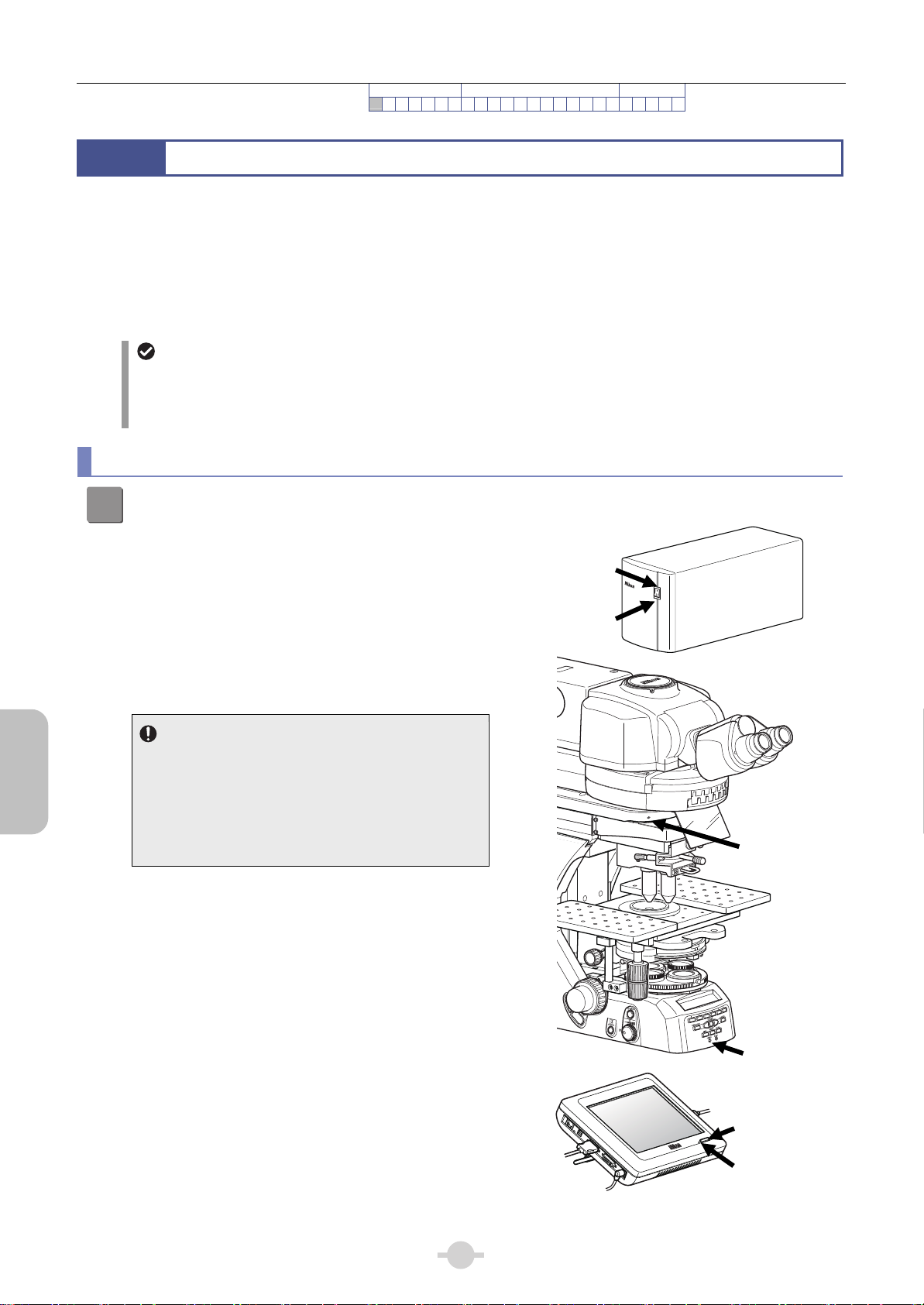
Preparation
Turn on the power.
1
Press the power switch to [|] to turn on the power.
(1) Turn on the power switches for all accessory devices
Power LED ON
connected. (Except DS-L3)
(The power LED on each device will light up.)
(2) Turn on the power for control box A.
(The power LED on the control box A, front of the
Power switch ON
microscope, and contact arm will light up.)
(3) Turn on the DS-L3 power switch.
Power on sequence
70
60
50
Turn on the power in the order described above. There
is no specific sequence for accessory devices.
However, when DS-L3 is connected, turn on control
5
4
3
2
1
box A before the DS-L3 power switch. This will load
data such as microscope’s system configuration and
settings into DS-L3.
Power LED ON
Power LED ON
Power switch ON
Power LED ON
Turning on the device
12

Chapter 2 Microscopy Operations
IR-DIC Microscopy
Turn on the dia-illumination lamp.
2
Press the dia-illumination lamp ON/OFF switch.
Display at power on
When the power is turned on, operation progress
is displayed on the front display panel of the main
body.
When initialization completes, microscope’s status
appears on the display panel. For details, see
Chapter 3, “1 Display Panel Details”.
Procedure
Preparation Focus and Orientation Microscopy
1 2 3 4 5 6 7 8 9 10 11 12 13 14 15 16 17 18 19 20 21 22 23 ■
_ Ni-E_ Vx.xx_xxxx.xxxx.F1
Data_ Loading...
_ Ni-E_ Vx.xx_xxxx.xxxx.F1
Initializing............
__________Z:_____0.000um
DIA:ON__________FS30.6mm
Top: Model name, firmware version
Bottom: Program startup progress
Top: Model name, firmware version
Bottom: Motorized device initialization
progress
Microscope state display
Display pattern 1: Factory setting example
Lamp ON, brightness adjustment
operation control
The lamp can also be turned on and adjusted from
DS-L3 by configuring the lamp control button on
the DS-L3’s [MICROSCOPE CONTROL] screen
or [CAM-MIC] screen. When Ni-E is turned on,
control switches on the Ni-E are enabled.
To control from DS-L3, switch the control to the
DS-L3 side by pressing the [LAMP CTRL] button
configured on DS-L3. When the button is checked,
the microscope can be controlled from DS-L3.
Turning on dial-illumination lamp
__________Z:_____0.000um
DIA:ON__________FS30.0mm
Voltage is not displayed.
DS-L3 [MICROSCOPE CONTROL] top screen
Microscopy
IR-DIC
[MIC] button: Switching to MICROSCOPE
CONTROL screen
[MICROSCOPE CONTROL] screen
[LAMP CTRL] button: Switch lamp control.
[LAMP ON/OFF] button: Turn on/off the lamp.
[ADJ.] button: Open the sub screen for
brightness control.
[PHOTO] button (on the sub screen):
Photomicrography voltage.
13
Chapter 2 Microscopy Operations
IR-DIC Microscopy
Procedure
Preparation Focus and Orientation Microscopy
123 4 5 6 7 8 9 10 11 12 13 14 15 16 17 18 19 20 21 22 23 ■
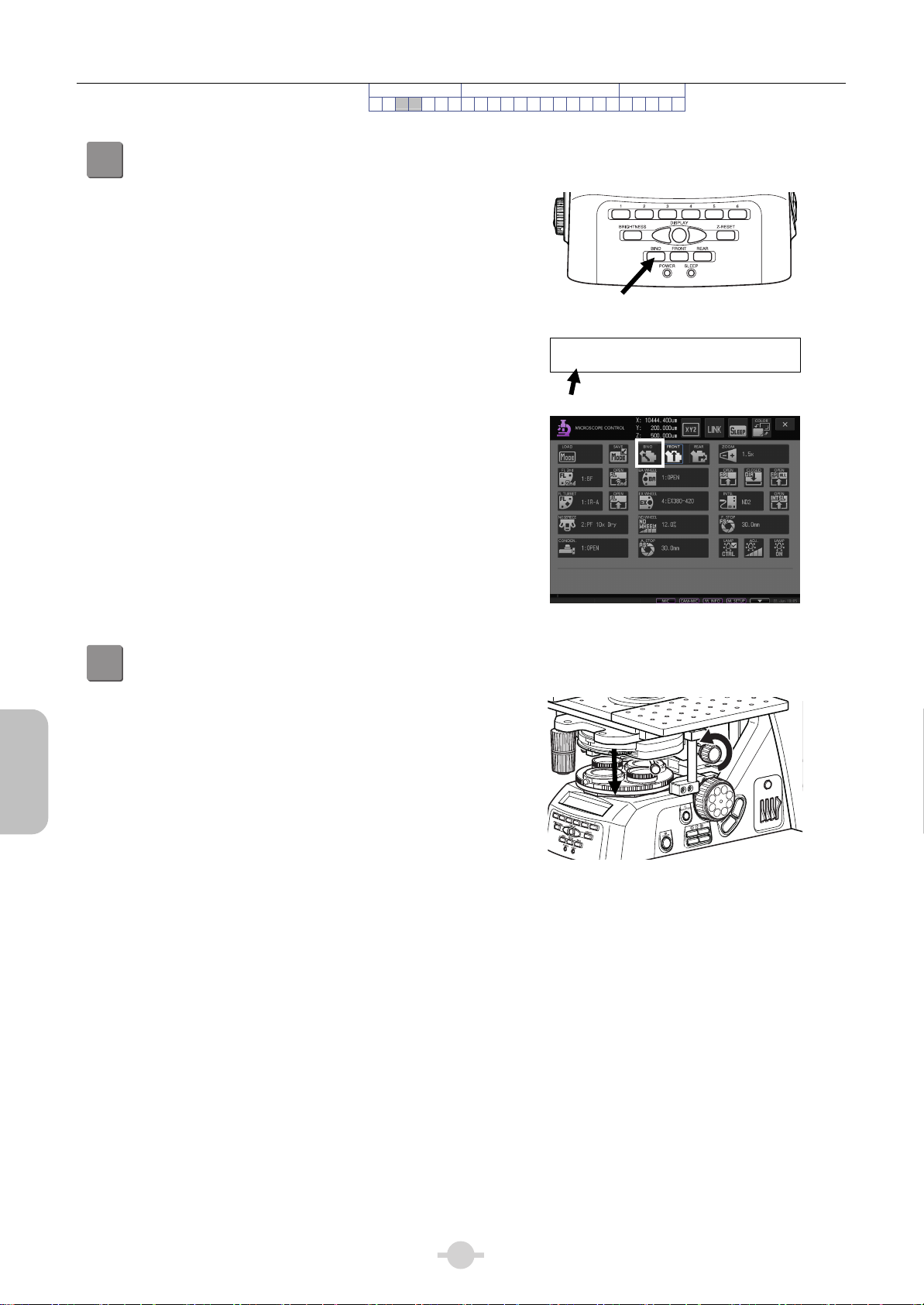
Adjust optical path in tube to direct 100% of
3
light to binocular.
Press the BINO optical path button on the front of the
main body.
There are three buttons on the front of the main body for
switching the optical path in the tube. The pressed button
is lit and that optical path status is set.
• BINO optical path button: 100% to binocular
• FRONT optical path button: 100% to tube adapter
• REAR optical path button: 100% to rear port
Binocular 100% with [BINO] button
__________Z:_____0.000um
BINO____ZM:1.0x_ FS30.0mm
Microscopy
IR-DIC
[BINO] button: Binocular optical path 100%
Lower the condenser slightly from the uppermost position.
4
Turn the condenser focus knob until the condenser is
positioned at the upper limit (where it clicks to a stop), and
then lower it a little.
NCB
ND
ND
32
8
OUT
IN
Lowering the condenser slightly
from uppermost position
using the condenser focus
knob
11
14
Chapter 2 Microscopy Operations
A
IR-DIC Microscopy
Procedure
Preparation Focus and Orientation Microscopy
12345 6 7 8 9 10 11 12 13 14 15 16 17 18 19 20 21 22 23 ■
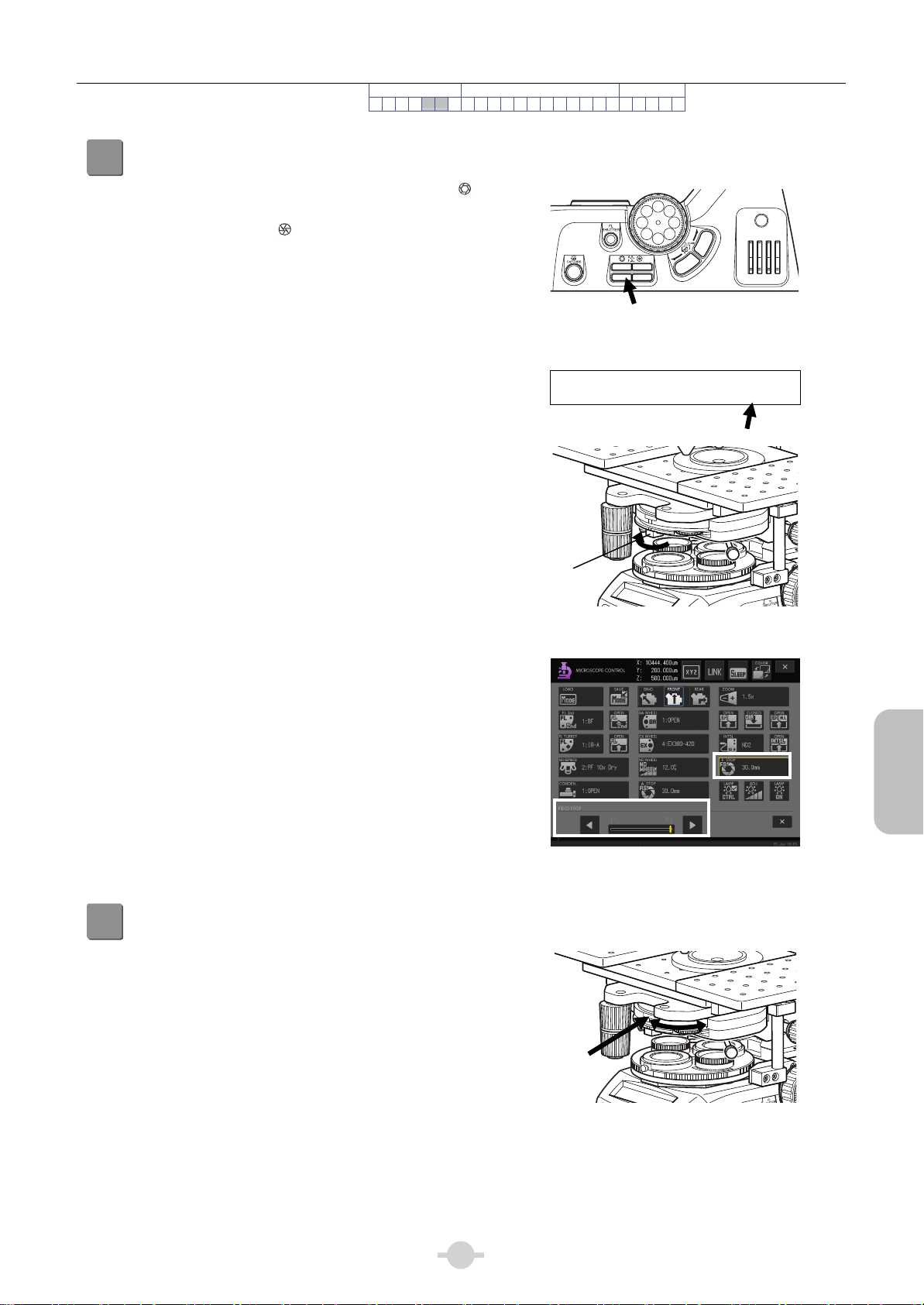
Fully open the field diaphragm and aperture diaphragm.
5
Press the left side of the DIA field diaphragm button (
mark side) and fully open the field diaphragm.
Pressing the right side (
mark) will close the diaphragm.
Turn the aperture diaphragm lever fully clockwise to open
the aperture diaphragm completely.
DIA field diaphragm button
--__--____Z:_____0.000um
OPEN____________FS30.6mm
OUT
IN
Field diaphragm fully open
ND8ND
NCB
11
32
perture
diaphragm
lever
[F. STOP] button, sub screen: DIA field diaphragm
Aperture diaphragm fully open
Microscopy
IR-DIC
open
Set the condenser turret to [O] position (empty: bright-field).
6
Turn the condenser turret and face the display [O] on the
turret to the front. The turret’s empty position enters the
optical path in this state.
Display [O]
Moving the condenser to the empty position
15
Microscopy
r
T
r
IR-DIC
Chapter 2 Microscopy Operations
IR-DIC Microscopy
Procedure
Preparation Focus and Orientation Microscopy
1234567 8 9 10 11 12 13 14 15 16 17 18 19 20 21 22 23 ■
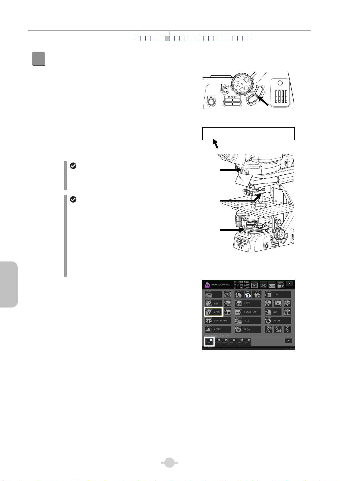
Move the epi-fluorescence cube turret to empty position,
7
and remove the DC slider (objective side) and polarizer from the optical path.
Press the FL CUBE CW/CCW button and bring the
epi-fluorescence cube turret’s [OPEN] (empty position)
into the optical path.
Pressing the FL CUBE CW button turns the turret by one
address in the clockwise direction (as viewed from
above), while the CCW button turns the turret in the
counterclockwise direction.
Bringing the [OPEN] position into optical path
If the DIC slider is in the objective side, pull it out and
remove it.
Turn the polarizer turret to bring the empty position into
the optical path.
Intelligent epi-fluorescence cube turret
Switch the intelligent epi-fluorescence cube turret
__________Z:_____0.000um
OPEN_______ND_ 1'C __EPI:C
Empty
position
manually because it is not motorized. On DS-L3,
only information display is provided.
FL/DIC analyzer slider NI-FA/dummy
slider
Remove
the DIC slide
For IR-DIC microscopy, the FL/DIC analyzer slide
inserted in the epi-fluorescence cube turret is not
used. If the analyzer slider is inserted, pull it out to
the first click-stop position and remove the
Empty
position
analyzer from the optical path. If a dummy slider is
inserted instead of the analyzer slider, be sure not
to insert all the way, but to pull it out by one
position.
Removing the DIC optical element from the optical
The periphery of field of view may be dark if it is
inserted all the way in.
NCB
ND8ND
11
32
OUT
IN
A. S
F. STOP
2
3
4
5
6
JAPAN
FN-S2N
EX. ADJ
ND
8
OUT
IN
path
[FL TURRET] button,
sub screen: [OPEN]
16
 Loading...