

Nikon ECLIPSE MA200 Instructions Manual

M498E 08.10.NF.1 (2/4)
Inverted Metallurgical Microscope
ECLIPSE MA200
Instructions


Introduction
Thank you for purchasing a Nikon product.
This instruction manual is written for users of Nikon Inverted Metallurgical Microscope ECLIPSE MA200.
To ensure correct usage, read this manual carefully before operating the product.
• No part of this manual may be reproduced or transmitted in any form without prior written permission from
Nikon.
• The contents of this manual are subject to change without notice.
• Although every effort has been made to ensure the accuracy of this manual, errors or inconsistencies may
remain. If you note any points that are unclear or incorrect, please contact your nearest Nikon
representative.
• Some of the equipment described in this manual may not be included in the set you have purchased.
• If you intend to use any other equipment with this product, read the manual for that equipment too.
• If the equipment is used in a manner not specified by the manufacturer, the protection provided by the
equipment may be impaired.
1
Safety Precautions
To ensure correct and safe operation, read this manual before using the product.
Warning and Caution Symbols Used in This Manual
Although this product is designed and manufactured to be completely safe during use, incorrect usage or
failure to follow the safety instructions provided may cause personal injury or property damage. To ensure
correct usage, read this manual carefully before using the product. Do not discard this manual and keep it
handy for easy reference.
Safety instructions in this manual are marked with the following symbols to highlight their importance. For your
safety, always follow the instructions marked with these symbols.
Symbol Description
Warning
Caution
Disregarding instructions marked with this symbol may lead to serious injury or
death.
Disregarding instructions marked with this symbol may lead to injury or property
damage.
Meaning of Symbols Used on the Product
Symbol Description
Caution for heat
This marking on the back of the lamphouse calls your attention on the following (the
position of this symbol is shown in Figure 1.1-3):
• The lamphouse becomes extremely hot while the lamp is on and immediately
after it is turned off.
• Do not touch the lamphouse during and immediately after lighting to prevent the
risk of burns.
• Make sure that the lamphouse is sufficiently cool before the lamp replacement.
2

Safety Precautions
WARNING
1. Intended product use
The product should only be used for microscopic observation. Do not use this microscope for other purposes.
Additionally, do not try to put a large sample on the stage if it is larger than the stage.
2. Do not disassemble
Disassembling the microscope or the microscope system may result in electric shock or malfunctions.
Damage or injury that may occur due to mishandling is unwarranted. Never attempt to disassemble any part
other than the parts described in this manual. If you experience problems with the microscope or the
microscope system, contact your nearest Nikon representative.
3. Read the instructions carefully
To ensure safety, carefully read this manual and the manuals for other equipment used with this microscope.
In particular, observe all
4. Ratings of the power supply
warnings and cautions given at the beginning of each manual.
The power supply circuit in this product is designed for AC power of 100 to 240 VAC and 50/60 Hz. Before
connecting the power cord, check that the power supply to be used conforms to the voltage and frequency
described above. Use of a non-conforming power line may result in equipment malfunction, failure or fire.
5. Power cord
Be sure to use the specified power cord for the product. Using a wrong power cord may result in malfunctions
or fire. The product is classified as subject to Class I protection against electrical shock. Make sure it is
connected to an appropriate ground terminal (protective earth terminal). To prevent electrical shock, always
turn off the power switch (set the switch to the “c” position) for the product before connecting or
disconnecting the power cord. For specifications of the power cord, refer to “7. Specifications.”
6. Specified light source
Use this product with a specified light source. The specified light source devices are shown as follows:
For the episcopic illumination
• Lamphouse
Nikon 12V 50W Precentered Lamphouse (model name: LV-LH50PC)
• Lamp
Nikon 12V 50W longlife halogen lamp (model name: LV-HL50W) or 12V 50W shortlife halogen lamp from
other manufacturers (model name: OSRAM HLX 64610, OSRAM HLX 64611, or PHILIPS 7027).
For the diascopic illumination
• Lamphouse
Nikon 12V 100W Precentered Lamphouse LC (model name: D-LH/LC)
• Lamp
Nikon 12V 100W halogen lamp (model name: OSRAM HLX 64623 or PHILIPS 77241).
• TI-PS 100W power supply
If you wish to buy these lamps, please contact your nearest Nikon representative.
3

Safety Precautions
7. Heat from the light source
The lamp and the lamphouse become extremely hot. To avoid burns, do not touch the lamphouse while the
lamp is lit or for thirty minutes after it is turned off. Additionally, to avoid the risk of fire, do not place fabric,
paper, or highly flammable volatile materials (such as gasoline, petroleum benzine, paint thinner, or alcohol)
near the lamphouse while the lamp is lit or for about thirty minutes after it is turned off.
8. Air vents
Do not block the air vents on the product and the lamphouse. If the air vents are blocked, the temperature
inside the product will rise. And it may result in damage or fire.
9. To use the HG Precentered Fiber Illuminator
To perform the epi-fl microscopy with this product, the brightness of the specified light source may be less
than the desired brightness. In this case, connect an external light source that has a mercury lamp, Nikon
INTENSILIGHT HG Precentered Fiber Illuminator (model: C-HGFI manual type, or C-HGFIE motorized type)
to MA200 to be used.
• Handling the mercury lamp
When using the mercury lamp, you must take great care of the lamp. Read the instruction manual for the
light source and follow the instructions and cautions.
• Ultraviolet light from an external light source
If you use an external light source other than the specified ones and that has a mercury lamp, the light
source radiates ultraviolet light, which is harmful to the eyes and skin, from the emission port. Direct
viewing of light from these lamps may result in snow blindness at a light case or blindness at the worst
case. To prevent injury, be sure to attach a fiber illuminator to the microscope.
The light source device is required to be connected to the microscope whenever the light source device is
energized. Do not turn on the light source if it is not connected to the microscope, and do not disconnect
the light source from the microscope while the light source is lit. When disconnecting the light source from
the microscope, turn off the power to the light source, and then unplug the power cord from the outlet.
4

Safety Precautions
CAUTION
1. Handle with care
This product is a precision optical instrument. Handle the microscope system with care to avoid shock on
impact. In particular, objectives may loose accuracy when exposed to even a weak physical shock.
2. Do not wet the microscope
If the product gets wet, a short circuit may cause malfunction or abnormal heating of the microscope. If you
accidentally spill water on the microscope, immediately turn off the power switch (set the switch to the “c”
side) and unplug the power cord from the outlet. Then, wipe off the water with a piece of dry cloth. If water
enters a component, immediately suspend use of this product, disconnect the power cord from the outlet, and
contact your nearest Nikon representative.
3. Weak electromagnetic waves
The product emits weak electromagnetic waves. The accuracy of any precision electronic equipment may be
adversely affected if positioned too close. To prevent bad influences, locate such electronic equipment away
from the microscope system. If a TV or radio reception is affected, move the TV or radio set farther from the
product.
4. Installation location
This product is a precision optical instrument. The usage or storage in an inappropriate environment may
result in malfunctions or poor performance. Consider the following factors when selecting an installation
location:
• Select an installation location with a temperature from 0 to +40°C and a relative humidity of 85% or less
(there should be no condensation).
Select a storage location with a temperature from -20 to +60°C and a relative humidity of 90% or less
(there should be no condensation).
If installed or stored in a location subject to high temperatures and humidity, mold or condensation may
form on the lens, resulting in lowered performance and possible damage to the microscope.
• Avoid a brightly lit location, such as exposed to direct sunlight or directly under a room light. If there is
excessive ambient light, the image may not clearly be visible.
• Always install the product with a surrounding clear area of 10 cm or more.
• Install the product in a location free from considerable dust or dirt.
• Install the product on a flat surface with little vibration.
• Install the product on a sturdy desk or table for the base of the microscope system.
• Select a layout that allows easy removal of the power cord from the AC inlet of the product in the event of
an emergency.
• Do not install in a narrow space such as a shelf or locker.
• Do not place anything on the product.
• Cover the product to avoid dust when storing.
• For details about the operating environment and storage environment, refer to “7. Specifications.”
5. Cautions on moving the microscope
• This product is a precision optical instrument. Handle it carefully and do not subject it to a strong physical
shock. (In particular, objectives may loose accuracy when exposed to even a weak physical shock.)
• Securely hold the microscope at the front bottom and rear bottom when carrying it.
5

Safety Precautions
• Do not hold the focus knobs, eyepiece tube, lamphouse, stage, and so on, when carrying the microscope.
They may come off and may cause serious injury or malfunction.
• Be careful not to pinch your hands or fingers during transportation.
6. Cautions on assembling the microscope
• Be careful not to pinch your fingers or hands during assembly.
• Scratches or fingerprints on the optical components, including lenses or filters etc., will adversely affect the
image. Be careful not to scratch or touch the lens surfaces.
7. Cautions on replacing lamps
• To prevent burn injuries, wait at least 30 minutes after the lamp is turned off to give it sufficient time to cool
down when replacing lamps.
• To prevent electrical shock and damage to the microscope, always turn off the power switch (set the switch
to the “c” side) and unplug the power cord from the outlet before attaching or detaching the lamphouse.
• Never touch the glass surface of the lamp with bare hands. Doing so may cause fingerprints, grease, etc.,
to generate ghost images on the lamp surface, reducing the illumination. If you do get any fingerprints or
dirt on the lamp, wipe them clean.
• Make sure the lamphouse cover is securely fitted to the lamphouse after replacing lamps. Never turn on
the lamp with the lamphouse cover removed.
• When you dispose of the replaced lamp, do not break it. Instead, dispose of the used lamp as industrial
waste or dispose of it according to the local regulations and rules.
8. Cable routing
Make sure the cables are routed properly. Do not bring the cables into contact with the lamphouse. If a cable
comes into contact with the lamphouse, the cable sheath may melt and it may result in an electrical shock or
fire. Additionally, connect the cables by placing them into the cable keeper on the rear of the microscope main
body.
6

Contents
Introduction ....................................................................................................................................................................... 1
Safety Precautions............................................................................................................................................................ 2
Warning and Caution Symbols Used in This Manual .................................................................................................2
Meaning of Symbols Used on the Product .................................................................................................................2
WARNING .......................................................................................................................................................... 3
CAUTION ...........................................................................................................................................................5
1. Part Name and Function........................................................................................................................................ 10
2. Microscopy .............................................................................................................................................................14
2.1 Bright-field Microscopy under the Episcopic Illumination ..............................................................................16
2.2 Dark-field Microscopy under the Episcopic Illumination ................................................................................ 19
2.3 Polarization Microscopy under the Episcopic Illumination (simplified/sensitive color)................................... 20
2.4 Differential Interference Contrast Microscopy under the Episcopic Illumination............................................ 21
2.5 Epi-fl Microscopy........................................................................................................................................... 22
2.6 Bright-field Microscopy under the Diascopic Illumination ..............................................................................24
2.7 Polarization Microscopy under the Diascopic Illumination (simplified/sensitive color)................................... 28
3. Operation Details....................................................................................................................................................29
3.1 Power ON/OFF ............................................................................................................................................. 29
3.1.1 Power of the microscope............................................................................................................... 29
3.1.2 Power supply of the lamp.............................................................................................................. 29
3.2 Illumination.................................................................................................................................................... 30
3.2.1 Brightness control and illumination ON/OFF .................................................................................30
3.2.2 Switching the Internal/External brightness control......................................................................... 30
3.2.3 Displaying the POWER LED .........................................................................................................31
3.3 Selecting the Microscopy Method ................................................................................................................. 31
3.4 Eyepiece Tube .............................................................................................................................................. 33
3.4.1 Selecting optical path .................................................................................................................... 33
3.4.2 Adjusting the eyelevel risers.......................................................................................................... 34
3.5 Adjusting the Interpupillary Distance............................................................................................................. 34
3.6 Adjusting the Diopters.....................................................................................................
3.7 Adjusting the Focus (for focus operation) ..................................................................................................... 36
3.7.1 Using the coarse/fine focus knob .................................................................................................. 36
3.7.2 Adjusting the torque for the coarse focus ring............................................................................... 36
3.8 Placing the Sample and Operating the Stage ...............................................................................................37
3.8.1 Placing the sample........................................................................................................................ 37
3.8.2 Changing the Observation Position............................................................................................... 38
3.9 Operating the Revolving Nosepiece and the Objective................................................................................. 39
3.9.1 Revolving nosepiece in combination with the objective................................................................. 39
3.9.2 Changing the objectives ................................................................................................................ 39
3.9.3 Displaying the address for the revolving nosepiece ...................................................................... 39
3.10 Filter.............................................................................................................................................................. 40
3.11 Adjusting the Field Diaphragm (for the episcopic Illumination) .....................................................................41
3.12 Adjusting the Aperture Diaphragm (for the episcopic illumination)................................................................ 42
3.13 Using the Polarizer/Analyzer Unit (MA2-PA/MA2-UPA) ................................................................................ 43
3.13.1 Inserting/removing the polarizer/analyzer from the optical path .................................................... 43
.............................. 35
7

Contents
3.13.2 Adjusting the polarizer direction.................................................................................................... 44
3.14 Using the λ Plate (MA2-λP)........................................................................................................................... 45
3.14.1 Inserting/removing the λ plate ....................................................................................................... 45
3.15 Using the DIC Slider (L-DIHC/L-DIC)............................................................................................................ 46
3.15.1 Inserting/removing the DIC prism from the optical path ................................................................ 46
3.15.2 Setting the DIC prism .................................................................................................................... 46
3.15.3 Interference color .......................................................................................................................... 47
3.16 Using the DIC Slider (LV-DIHC/LV-DIC)........................................................................................................ 47
3.16.1 Selecting the DIC slider................................................................................................................. 47
3.16.2 Inserting/removing the DIC slider from the optical path................................................................. 47
3.16.3 Interference color .......................................................................................................................... 48
3.17 Using the Analyzer Slider (D-DA).................................................................................................................. 48
3.17.1 Inserting/removing the analyzer from the optical path................................................................... 48
3.18 Using the λ Plate (D-LP) ............................................................................................................................... 49
3.18.1 Inserting/removing the λ plate from the optical path...................................................................... 49
3.19 Using the Fluorescent Unit (MA2-FL)............................................................................................................ 50
3.19.1 Inserting/removing the fl filter from the optical path....................................................................... 50
3.19.2 Excitation light filter (EX filter) .......................................................................................................51
3.19.3 Barrier filter (BA filter).................................................................................................................... 52
3.20 Using the Scale Slider (MA2-GR/MA2-MR) .................................................................................................. 53
3.20.1 Grain scale slider (MA2-GR) ......................................................................................................... 53
3.20.2 Scale slider (MA2-MR) .................................................................................................................. 54
3.21 Using the Intermediate Magnification Unit (MA2-MC) ........................................................................
3.22 Using the HG Precentered Fiber Illuminator (C-HGFI/C-HGFIE).................................................................. 56
3.22.1 Procedure for turning on the power switch .................................................................................... 56
3.23 Using the supporting pillar for dia-Illuminator 100W (MA2-DP)..................................................................... 57
3.23.1 Procedure for turning on the power switch .................................................................................... 57
3.23.2 Focusing and centering the condenser ......................................................................................... 58
3.23.3 Adjusting the field diaphragm (for the diascopic illumination)........................................................ 59
3.23.4 Adjusting the aperture diaphragm (for the diascopic illumination) ................................................. 60
3.23.5 Diascopic illumination filter ............................................................................................................ 60
3.23.6 Condenser refocusing clamp......................................................................................................... 61
3.23.7 Condenser mount rotation............................................................................................................. 61
3.23.8 Polarizer slider (T-P2), λ plate (TI-DIC) ......................................................................................... 62
3.24 Using the Supporting Arm (MA2-MP) ............................................................................................................ 64
3.25 Using the DS Camera Control Unit (DS-L2).................................................................................................. 65
3.25.1 Procedure for turning on the power............................................................................................... 65
3.25.2 Displaying the microscope info menu............................................................................................ 65
3.25.3 Measurement corresponding to the magnification value of the microscope .................................. 66
3.25.4 Recording the microscope info while saving the image................................................................. 66
3.25.5 Connecting with the DS camera head switcher (DS-SW: Camera switch BOX, optional) ............. 67
........... 55
4. Assembly ................................................................................................................................................................ 68
4.1 About the System.......................................................................................................................................... 70
4.2 Combination List for the Unit......................................................................................................................... 71
8

Contents
4.3 Network Connection...................................................................................................................................... 73
4.3.1 Unit system capable of establishing network................................................................................. 73
4.3.2 Viewing user control options and status displays on a PC or the DS-L2....................................... 74
4.3.3 Registering information on the objective .......................................................................................76
4.3.4 Procedure for turning on the power switch.................................................................................... 76
4.4 The LV-LH50PC Lamphouse and the Lamp.................................................................................................. 77
4.4.1 Attaching the lamphouse............................................................................................................... 77
4.4.2 Replacing the lamp ....................................................................................................................... 78
4.5 Revolving Nosepiece .................................................................................................................................... 78
4.5.1 Attaching the nosepiece................................................................................................................ 78
4.5.2 Cable connection for the manual revolving nosepiece and the MA200......................................... 79
4.5.3 Connecting the motorized nosepiece and the Nosepiece Controller 2.......................................... 79
4.6 Stage.............................................................................................................................................................80
4.6.1 Sample holder ............................................................................................................................... 80
4.7 Objectives ..................................................................................................................................................... 81
4.8 Eyepiece Tube .............................................................................................................................................. 81
4.9 Eyepieces ..................................................................................................................................................... 81
4.10 Grain Scale Slider/Scale Slider..................................................................................................................... 82
4.11 Filters ............................................................................................................................................................ 82
4.12 Various Sliders Available for Attaching the Revolving Nosepiece ................................................................. 83
4.12.1 L-DIC/L-DIHC slider (single NR method) ...................................................................................... 83
4.12.2 LV-DIC/LV-DIHC slider (Senarmont method)................................................................................. 84
4.12.3 D-DA analyzer slider, D-LP λ plate................................................................................................ 84
4.13 Polarizer/analyzer Unit and Fluorescent Unit................................................................................................ 85
4.13.1 MA2-λP λ plate .............................................................................................................................. 85
4.14 Intermediate Magnification Unit..................................................................................................................... 86
4.15 External Light Source.................................................................................................................................... 87
4.15.1 C-HGFI/C-HGFIE HG Precentered Fiber Illuminator..................................................................... 87
4.15.2 Attaching the MA2-DP supporting pillar for dia-Illuminator 100W.................................................. 88
4.16 Supporting Arm (for DS-L2) .......................................................................................................................... 94
4.17 Eyelevel Risers ............................................................................................................................................. 96
4.18 Camera Adapter............................................................................................................................................ 97
4.19 Power Cord................................................................................................................................................... 97
5. Troubleshooting ..................................................................................................................................................... 98
5.1 Viewing Problems and Control Problems...................................................................................................... 98
5.2 Electrical System Problems ........................................................................................................................ 101
6. Care and Maintenance ......................................................................................................................................... 102
6.1 Cleaning the Lenses and Filters.................................................................................................................. 102
6.2 Cleaning the Painted Parts, Plastic Parts, and Printed Parts ...................................................................... 102
6.3 Storage ....................................................................................................................................................... 103
6.4 Regular Inspections (fee charged) .............................................................................................................. 103
7. Specifications....................................................................................................................................................... 104
9
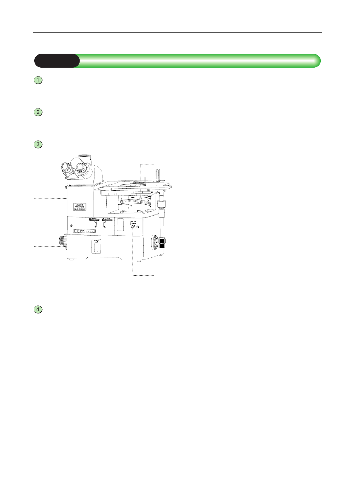
1
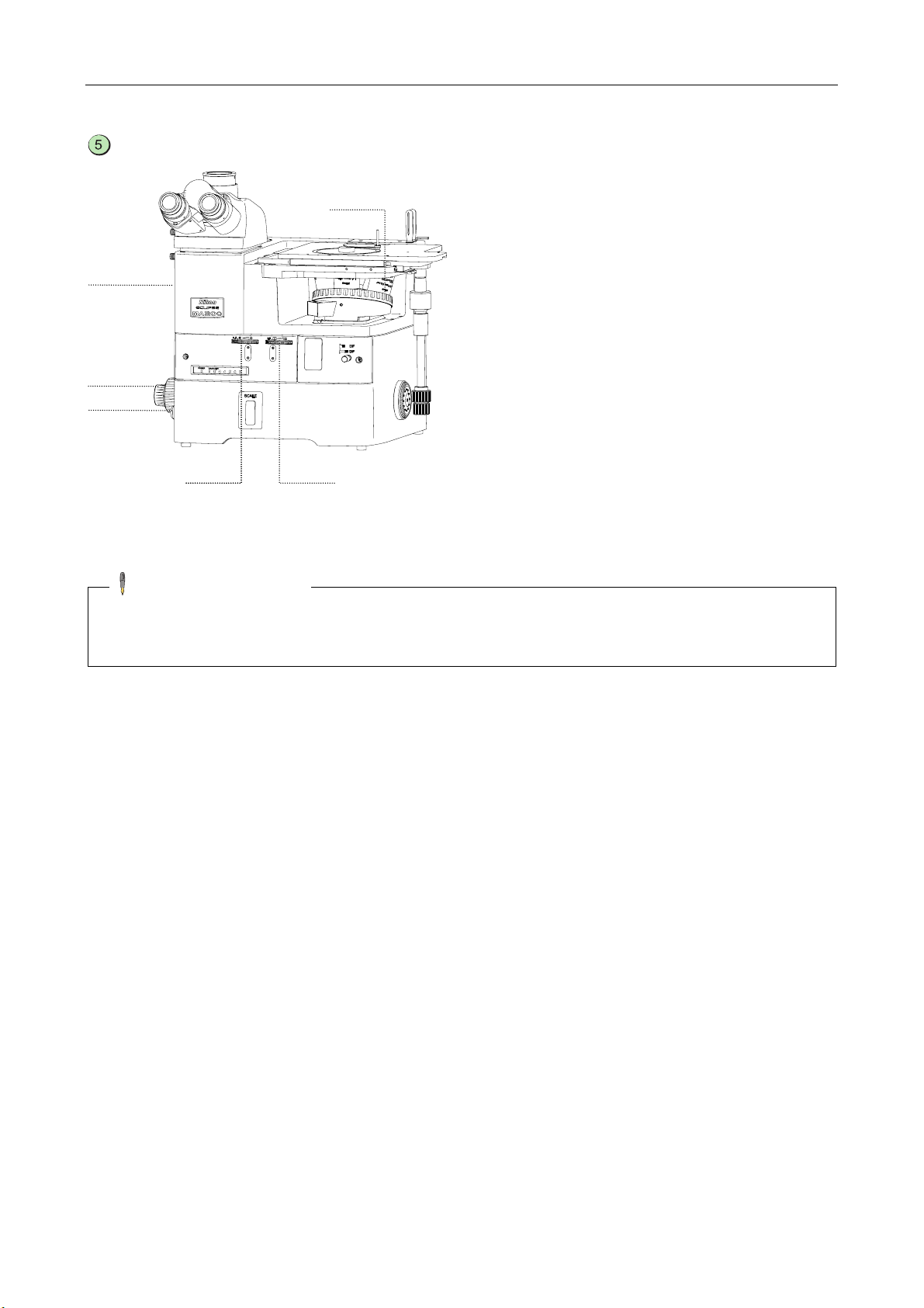
A
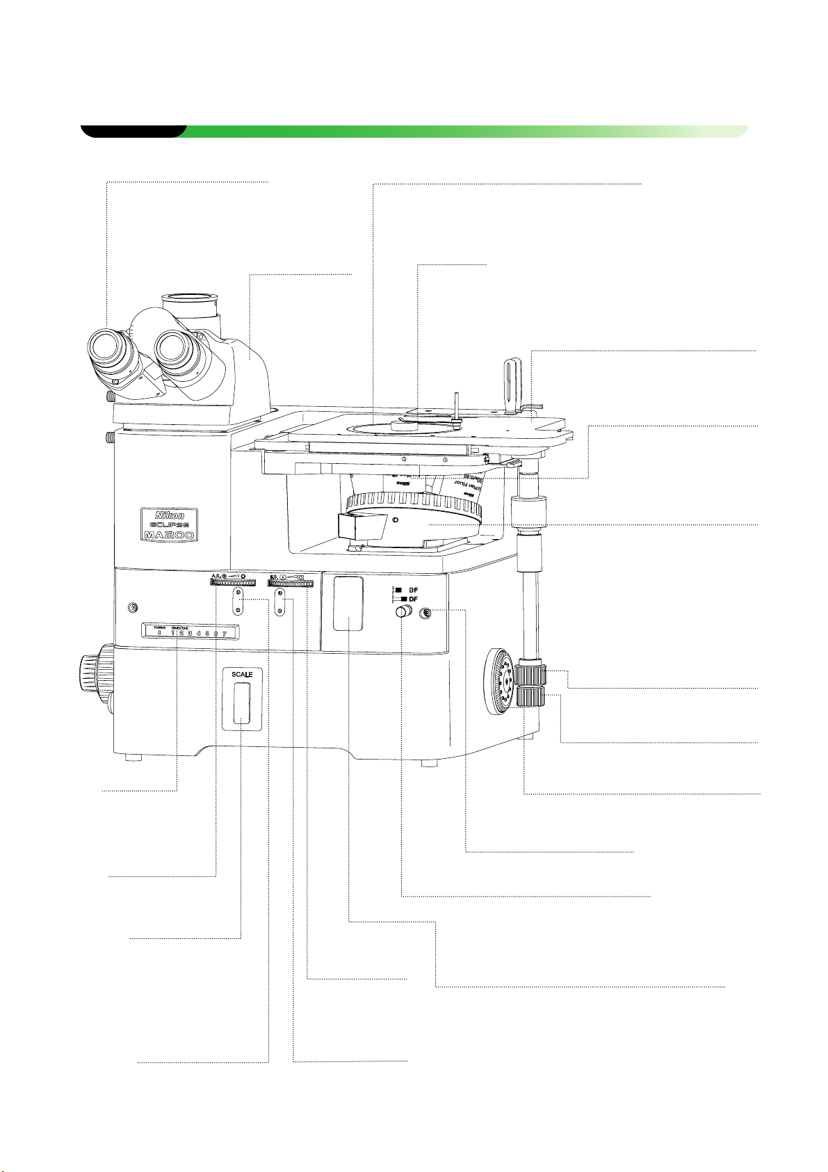
Part Name and Function
Eyepiece
10X, 12.5X, 15X (and 10X
are equipped with the
mask eyepiece.)
Eyepiece tube
(Figure illustrates
the MA2-TI3.)
Binocular eyepiece
may also be used.
(Refer to 3.4, 3.5,
and 3.6.)
Sample holder
The stage is equipped with the standard
sample holder (with a sample clip). (Refer to
3.8.)
Sample clip
Stage (Figure illustrates the MA2-SR.)
(Refer to 3.8.)
Objectives
(Refer to 3.9.)
Nosepiece (Figure illustrates the
MA2-NUI5.)
Quintuple, sextuple and septuple
revolving nosepieces may be used.
(Refer to 3.9.)
The DIC slider, analyzer slider etc.,
can be attached, depending on the
revolving nosepiece used.
Display
(Refer to Figure
1.1-2.)
Aperture
diaphragm dial
(Refer to 3.12.)
Scale slider slot
(Refer to 3.20.)
scale slider or scale
slider.
ttach the grain
Aperture diaphragm
centering holes
Front-cover fixing bolt
BD field changeover lever
Press (BF): Bright-field
Pull (DF): Dark-field (Refer to 3.3.)
Field diaphragm
dial
(Refer to 3.11.)
Field diaphragm
centering holes
Figure 1.1-1 Front view, Right-side view
Operation port for the polarizer/analyzer unit
and the fluorescent unit
(Refer to 3.13 and 3.19.)
To perform the polarization microscopy, differential
interference contrast microscopy or fluorescent
microscopy, remove the front cover to attach the
desired unit for the microscopy to be performed.
Stage (forward/backward)
movement knob for the Y
direction
Stage (left /right) movement
knob for the X direction
Fine focus knob
(Refer to 3.7.) Located also on the left.
10
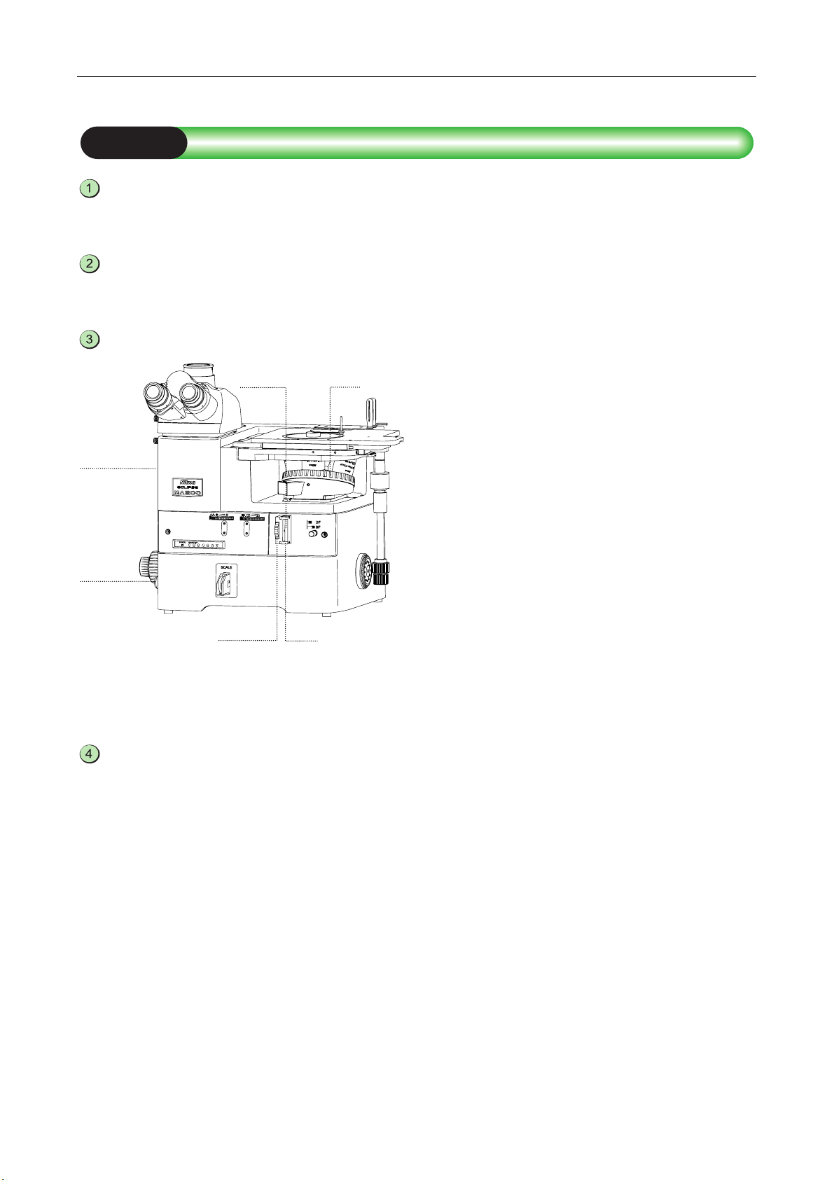
Chapter 1 Part Name and Function
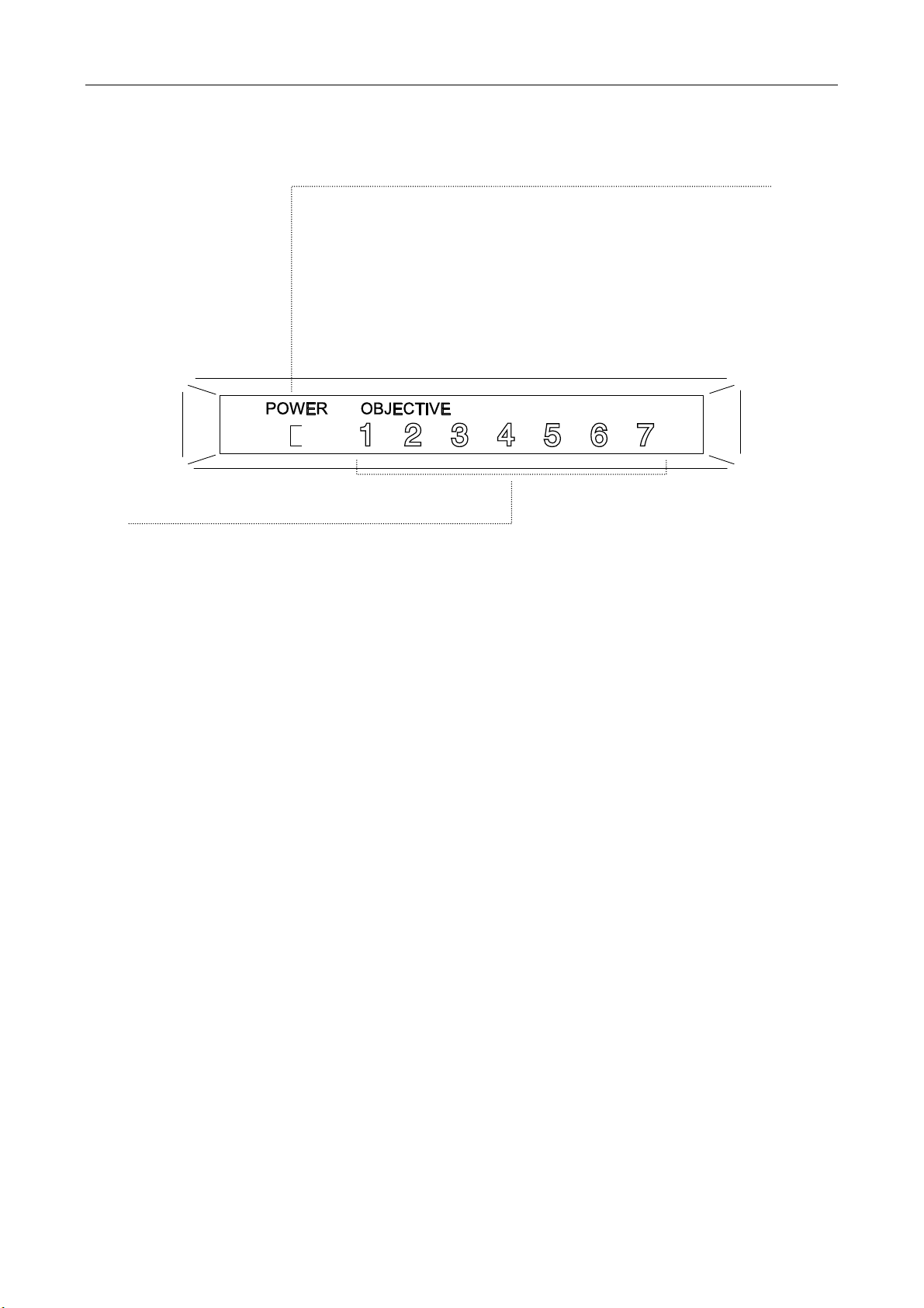
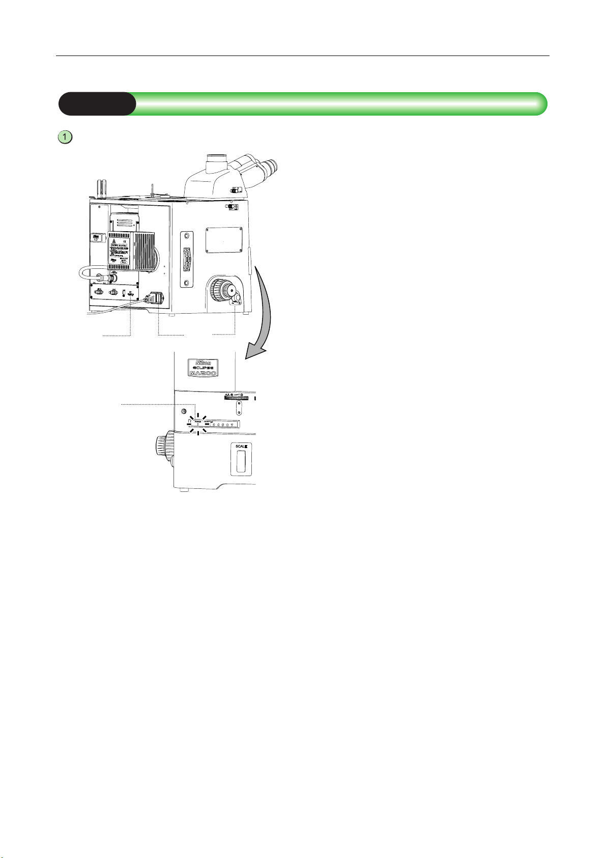
A
POWER LED
Displays ON/OFF for the power switch or the light-status for the illumination
lamp. Additionally, the display status remains the same when an external
PC is in use.
Power switch OFF: LED turns off
Power switch ON; Brightness control dial OFF: Orange LED lights up
Power switch ON; Brightness control dial ON: Green LED lights up
Note: The Power LED Message is only compatible with the lamphouse of
the MA200 main body for the episcopic illumination, and the HG
precentered fiber illuminator (C-HGFIE motorized type).
Address display
ddress of the objective in the optical path lights up.
Figure 1.1-2 Front view Display
11
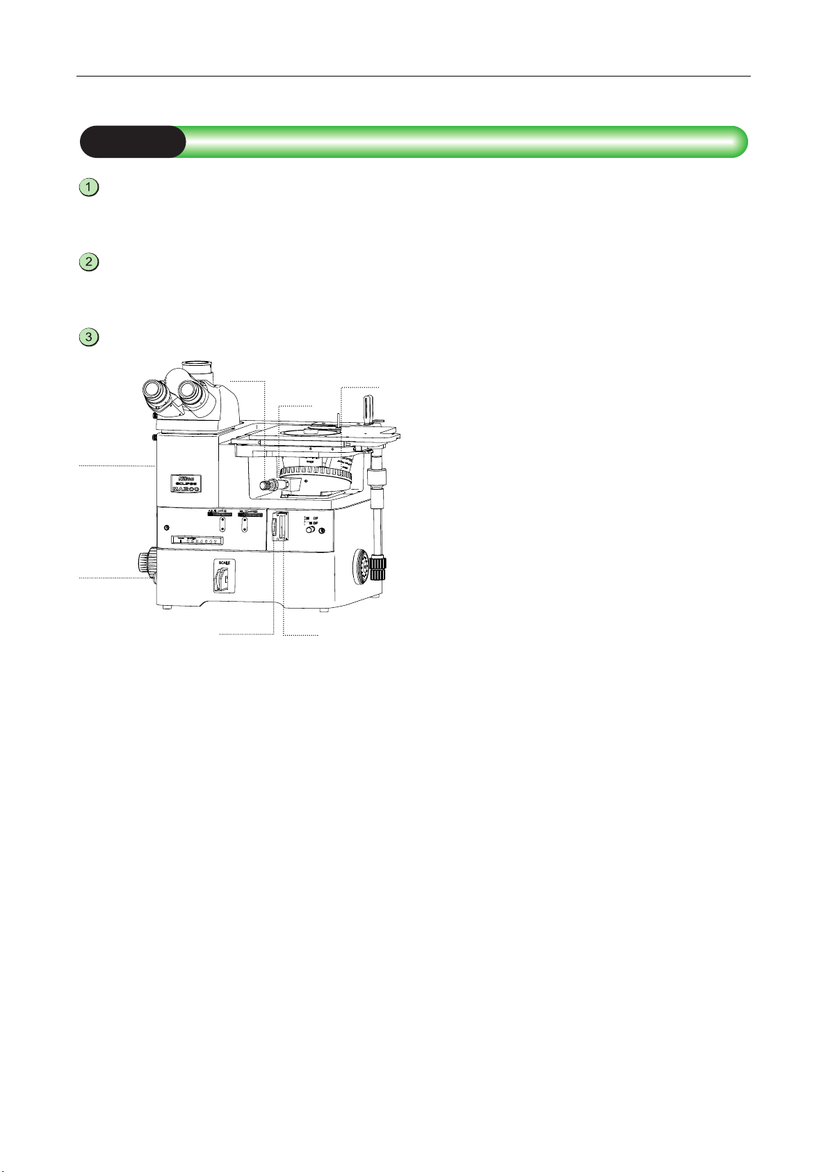
Chapter 1 Part Name and Function
A
A
A
A
A
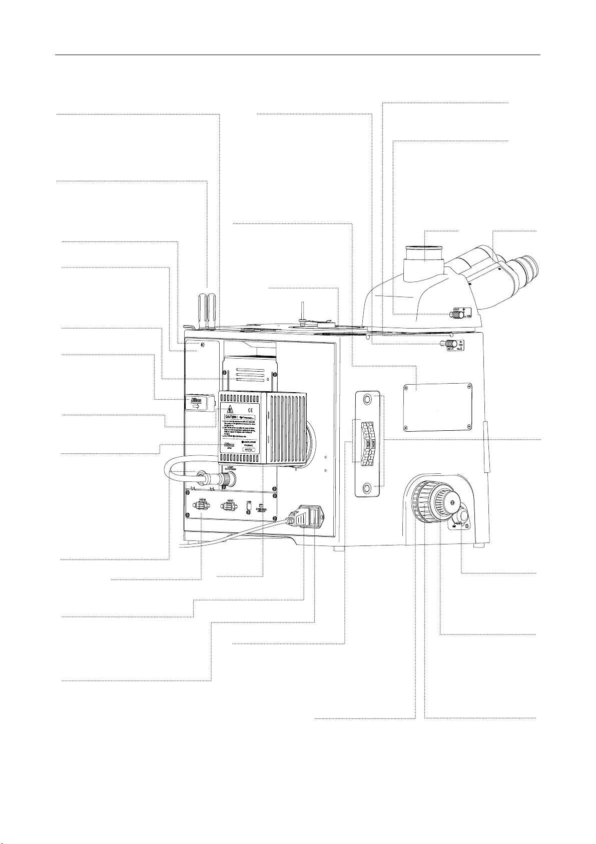
Supporting Pillar for Dia-Illuminator
100W/Supporting Arm for DS-L2
attaching part
(Refer to 3.23 and 3.24.)
ttach the supporting pillar for
dia-Illuminator 100W or the supporting
arm for DS-L2.
Tool storage
Stores the supplied hexagonal
wrench and two hexagonal
screwdrivers.
Rear-panel clamp screw
Rear-panel
Remove the rear-panel
cover for cable connection
of the revolving nosepiece.
Air vents
Cable keeper
Keeps cables inside.
“CAUTION for heat”
symbol
Epi illumination
lamphouse
(LV-LH50PC Lamphouse)
ttach an HG precentered
fiber illuminator instead of
LV-LH 50PC Lamphouse,
if necessary.
Signal cable hole for the
nosepiece controller 2
AC inlet
Connects the power cord exclusive
for the region of the product used
(optional).
Power switch
(Refer to 3.1.)
Set the switch to the “|” side to turn
on the power, or to the “c” side to
turn off the power.
When the power is turned on, the
POWER LED on the front-display
lights up.
Connectors
(Refer to Figure 1.1-4.)
Optical path changeover
lever (eyepiece tube/back
port)
(Refer to 3.4.)
Press: Eyepiece tube/back
port =100/0
Pull: Eyepiece tube/back port
=55/45
Attaching part for the
intermediate magnification
unit
(Refer to 3.21.)
ttach this unit to change
observation magnifications.
Lamp air
vents
Filter turret
(Refer to 3.10.)
Switch the turret when the ND
filter or other filters is/are turned.
Figure 1.1-3 Left view, Rear view
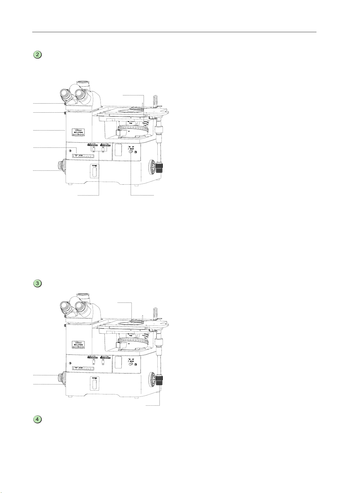
Back port
Coarse torque
adjustment ring
(Refer to 3.7.)
djusts the rotation
residence.
Eyepiece tube clamp screw
Optical path changeover lever
(vertical tube/binocular tube)
(Refer to 3.4.)
Press: Binocular/vertical tube=100/0
Pull: Binocular/vertical tube=0/100
Vertical
tube
Fine focus knob
(Refer to 3.7.)
Focus on the sample by
slightly lifting/lowering the
revolving nosepiece with
the fine knob.
Coarse focus knob
(Refer to 3.7.)
Focus on the sample roughly
lifting/lowering the revolving
nosepiece with the coarse
knob.
Binocular
tube
Clamp
screws for
the filter
turret
Brightness control
dial
(Refer to 3.2.)
djusts the brightness
of the lamp.
12
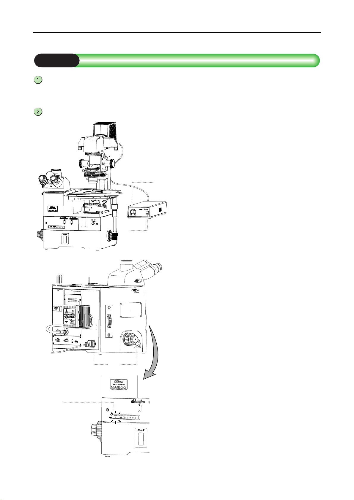
Chapter 1 Part Name and Function
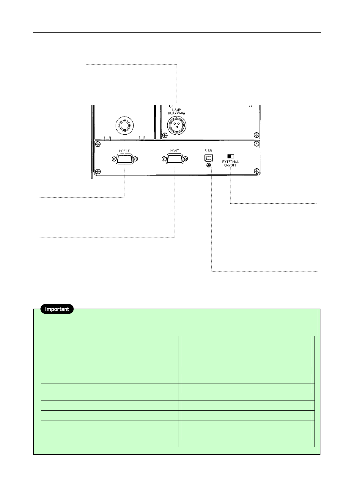
Lamphouse connector
[LAMP DC12V50W]
Connects the cord on the epi
illumination lamphouse (12V
50W Precentered Lamphouse).
RS232C connector [HGFIE]
Connects the C-HGFIE HG
Precentered Fiber Illuminator.
RS232C connector [NCNT]
Connects the LV-NCNT2
control unit for the motorized
nosepiece.
Figure 1.1-4 Connectors on the rear
Internal/External brightness
control changeover switch
[EXTERNAL ON/OFF]
(Refer to 3.2.2, 3.22.1, and
3.23.1.)
ON: Adjusts the brightness on
PC;
OFF: Adjusts the brightness on
the microscope.
USB connector [USB]
Connects a PC or the DS-L2.
About product parts names in this manual
The right column of the table below shows the product parts names described in this manual.
Package names Parts names in the ECLIPSE MA200 Instructions
MA2-TI3 Trinocular Eyepiece Tube ESD (erect image) MA2-TI3 Trinocular Eyepiece Tube
MA2-NUI5 Intelligent Universal Quintuple
Nosepiece ESD
MA2-MC Magnification Module MA2-MC Intermediate Magnification Unit
Fl Filter Block MA2-FL G
(Other types than G are available.)
MA2-GR Grain Size Slider MA2-GR Grain Scale Slider
MA2-PA Polarizing Filter Cube MA2-PA Polarizer/Analyzer Unit
MA2-UPA Polarizing Filter Cube with 1/4λPlate MA2-UPA Polarizer/Analyzer Unit
MA2-SRSH 10 Specimen Holder
(Other types than SRSH 10 are available.)
MA2-NUI5 Revolving Nosepiece
General name: MA2-FL Fluorescent Unit
General name: Sample Holder
13

2
Microscopy
This chapter describes the procedure of each microscopy.
See Table 2.1 for the items required for each microscopy.
• Refer to “4. Assembly,” when the product has not been assembled yet.
• For detailed information about operations of parts of the product, refer to “3. Operation Details.”
• Notes on using an external light source:
The procedures described on the episcopic illumination in 2.1 to 2.5 are based on use of the light source of
the MA200 main body with the LV-LH50PC Lamphouse attached. When using an external light source to
perform the microscopy, follow the notes below.
• The procedure on how to turn the power switch to ON: Turn on the power switch on the external device
in advance, then turn on the MA200 main body.
• Setting the Internal/External brightness control changeover switch of the MA200 main body: Sets to ON
(external mode).
• Adjusting the brightness of the light source: Adjusts the brightness on the external light source.
• To perform the epi-fl microscopy using the C-HGFI/C-HGFIE HG Precentered Fiber Illuminator as the
external light source, screw the compensation filter supplied with the fiber adapter into the MA2-FL
fluorescent unit. (Refer to 4.15.1.)
14

Chapter 2 Microscopy
Table 2.1 Items required for the microscopy
Microscopy Page Illuminator Revolving nosepiece Objective Other items required
BF microscopy
under the epi
illumination
DF microscopy
under the epi
illumination
Simplified
polarization
microscopy
under the epi
illumination
DIC microscopy
under the epi
illumination
Epi-fl
microscopy
BF microscopy
under the dia
illumination
Simplified
polarization
microscopy
under the dia
illumination
p.16 to p.18 5 revo., 6 revo.,
7 revo.
p.19 5 revo. only BD objective only
p.20 5 revo., 6 revo., 7
revo.
p.21 to p.22 5 revo., 6 revo. LU EPI objectives or LU BD
LV-LH 50PC
Lamphouse or
C-HGFI/C-HGFIE
HG Precentered
Fiber Illuminator
p.22
p.23 to p.26 5 revo., 6 revo., 7
Supporting pillar
p.27
for dia-Illuminator
100W
(+ condenser,
D-LH/LC
Lamphouse, 12V
100W halogen
lamp)
5 revo., 6 revo., 7
revo.
revo.
5 revo., 6 revo., 7
revo.
• For EPI objectives with 5
revo., LU nosepiece
adapter M32-25 required
• For 6 or 7 revo., BD
objective unavailable
• For EPI objectives with 5
revo., LU nosepiece
adapter M32-25 required
• For 6 or 7 revo., BD
objective unavailable
objective only
• For EPI objectives with 5
revo., LU nosepiece
adapter M32-25 required
• BD objective unavailable
for 6 revo.
LU EPI objectives or LU BD
objective only
• For EPI objectives with 5
revo., LU nosepiece
adapter M32-25 required
• For 6 or 7 revo., BD
objective unavailable
• For EPI objectives with 5
revo., LU nosepiece
adapter M32-25 required
• For 6 or 7 revo., BD
objective unavailable
• For EPI objectives with 5
revo., LU nosepiece
adapter M32-25 required
• For 6 or 7 revo., BD
objective unavailable
⎯
⎯
• MA2-PA/MA2-UPA
polarizer/analyzer unit
• For the sensitive color
polarization microscopy,
MA2-λP λ plate available
For 5 revo.:
• MA2-PA
polarizer/analyzer unit
• L-DIHC/L-DIC slider
(single NR method)
• For the sensitive color
polarization microscopy,
the MA2-λP λplate
available
For 6 revo.:
• MA2-UPA
polarizer/analyzer unit
• LV-DIH C / LV- D I C s l i d e r
(Senarmont method)
• For the sensitive color
polarization microscopy,
the MA2-λP λplate
available
• MA2-FL fluorescent unit
⎯
• T-P2 polarizer
• MA2-PA/MA2-UPA
polarizer/analyzer unit (for
6 revo., the D-DA analyzer
is also available)
• For the sensitive color
polarization microscopy,
TI-DIC λplate available
(for 6 revo., the D-LP
λplate is also available)
15
Chapter 2 Microscopy
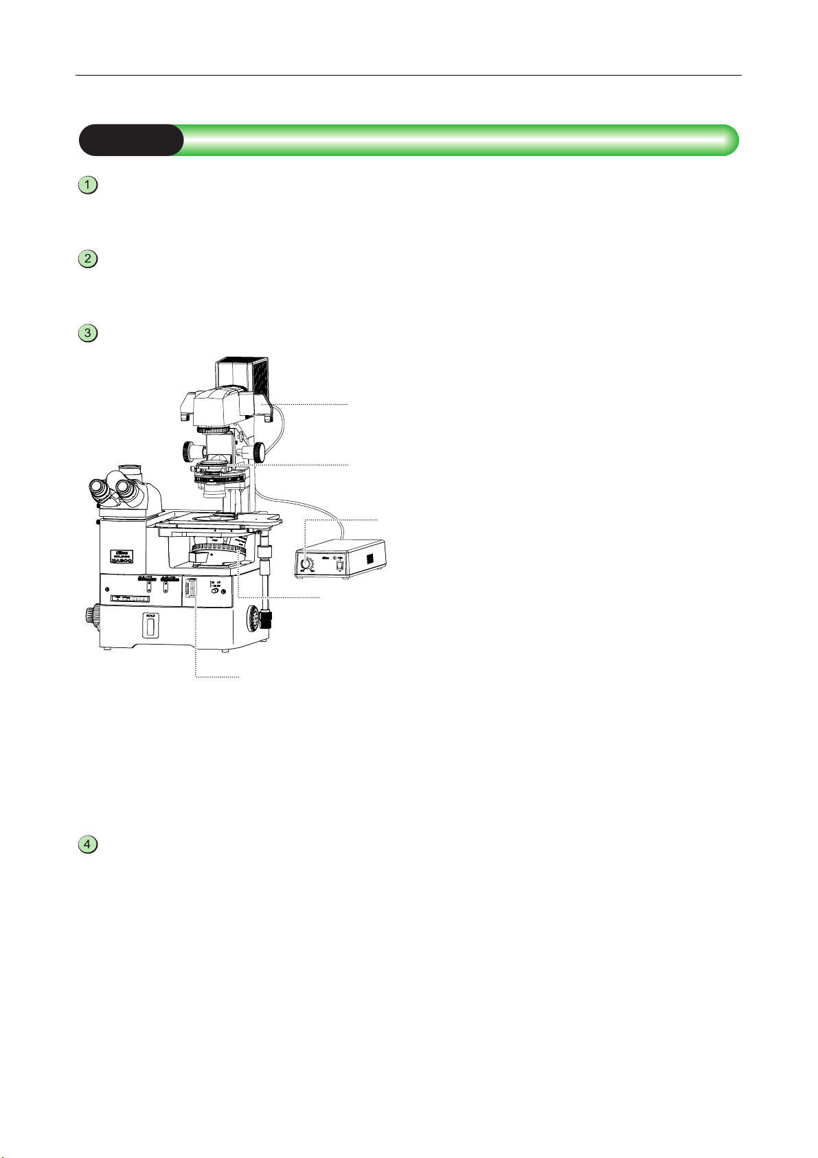
2.1 Bright-field Microscopy under the Episcopic Illumination
Turn on the power to light up the episcopic illumination lamp.
1 Turn on the power switch. (See 3.1.1.)
The power LED on the front is lit.
2 Be sure that the Internal/External brightness
control changeover switch is set to OFF “internal
mode.” (See 3.2.2.)
3 Turn the brightness control dial to light up the
lamp. (See 3.2.1.)
1-1 1-2
1-1
1-3
16
Chapter 2 Microscopy
Set the microscope for the bright-field microscopy under the episcopic illumination.
If the current unit is the one shown in the column at the right edge under “Other items required” in Table 2.1,
pull out each item from the optical path.
1 Push in the optical path changeover lever for the
eyepiece tube and select 100% for the binocular
eyepiece. (See 3.4.1.)
2 Push in the eyepiece tube/back port changeover
lever to select 100% for the eyepiece tube. (See
3.4.1.)
3 Push in the BD field changeover lever to select the
“BF (bright-field)” position. (See 3.3.)
4 Turn the revolving nosepiece to place the 10X
objective into the optical path. (See 3.9.2)
The nosepiece addresses (1 to 7) on the
front-display light up to indicate the position of the
revolving nosepiece. (See 3.9.3.)
5 Place the NCB11 filter in the filter turret into the
optical path and compensate color temperature.
(See 3.10)
6 Adjust the brightness roughly with the brightness
control dial and the desired ND filter in the filter
turret. (See 3.2.1 and 3.10.)
7 Turn the field diaphragm dial and the aperture
diaphragm dial counter-clockwise to the limit to
fully open the field diaphragm and the aperture
diaphragm for the episcopic illumination. (See 3.11
and 3.12.)
2-1
2-2
2-5, 6
2-4
2-6
2-7
2-4
2-3
Place the sample onto the stage and adjust the focus and the brightness.
1 Use the sample holder according to the selected
sample. Place the sample onto the stage and
move the stage using the stage movement knob
for the X/Y direction so that the observation
position comes to the center of the view-field. (See
3.8.)
2 Turn the coarse/fine focus knobs and focus on the
target. (See 3.7.)
3 Turn the brightness control dial to adjust the
brightness of the episcopic illumination. (See
3.2.1.)
3-2
3-3
3-1
3-1
Adjust the diopter and the interpupillary distance.
1 Adjust the interpupillary distance. (See 3.5.)
2 Adjust the diopter. (See 3.6.)
17
Chapter 2 Microscopy
Set the desired magnification and observe the sample.
1 Turn the revolving nosepiece to place the
objective of a desired magnification into the optical
path. (See 3.9.2.)
2 Turn the coarse/fine focus knobs and refocus on
the sample. (See 3.7.)
3 Turn the brightness control dial to adjust the
brightness of the episcopic illumination. (See
3.2.1.)
4 Turn the field diaphragm dial so that the field
diaphragm image circumscribes the view-field.
(See 3.11.)
5 Turn the aperture diaphragm dial so that the
aperture diaphragm image becomes 70 to 80% of
the numerical aperture of the objective. (See
3.12.)
6 Adjust the brightness with the desired ND filter in
the filter turret. (See 3.10.)
5-6
5-2
5-3
5-5
5-1
5-4
Note: Adjusting focus
It may be difficult to focus on a sample with small contrast, such on a polished surface. In a case like
this, stop down the field diaphragm so that its image can be seen in the view-field, and try to focus on
the frame of the diaphragm image. When the frame is in focus, the sample is in focus just as well.
18
Chapter 2 Microscopy
2.2 Dark-field Microscopy under the Episcopic Illumination
Attach the items required for the dark-field microscopy under the episcopic illumination
to the microscope. (See Table 2.1.)
Focus on the sample with the bright-field microscopy under the episcopic illumination.
(See Pages 16 and 17.)
Set the microscope for the dark-field microscopy under the episcopic illumination.
3-1
1 Turn the revolving nosepiece to place the
objective of a desired magnification into the optical
path. (See 3.9.2.)
2 Pull out the BD field changeover lever to select the
“DF (dark-field)” position. (See 3.3.)
3-4
The aperture diaphragm and the field diaphragm
are fully opened. (The dial positions do not
change.)
When the polarizer/analyzer or the fl filter is
placed into the optical path, it is automatically
excluded.
3-3
3 Turn the brightness control dial to adjust the
brightness of the episcopic illumination. (See
3.2.1.)
3-2
4 Adjust the brightness with the desired ND filter in
the filter turret. (See 3.10.)
Return to the bright-field microscopy under the episcopic illumination.
1 Push in the BD field changeover lever to select the
“BF (bright-field)” position. (See 3.3.)
The aperture diaphragm and the field diaphragm
automatically return to the previous positions.
(The dial positions do not change.)
2 Turn the brightness control dial to adjust the
brightness of the episcopic illumination. (See
3.2.1)
3 Adjust the brightness with the desired ND filter in
the filter turret. (See 3.10.)
19
Chapter 2 Microscopy
2.3
Polarization Microscopy under the Episcopic Illumination (simplified/sensitive color)
Attach the items required for the polarization microscopy under the episcopic
illumination to the microscope. (See Table 2.1.)
Focus on the sample with the bright-field microscopy under the episcopic illumination.
(See Pages 16 to 17.)
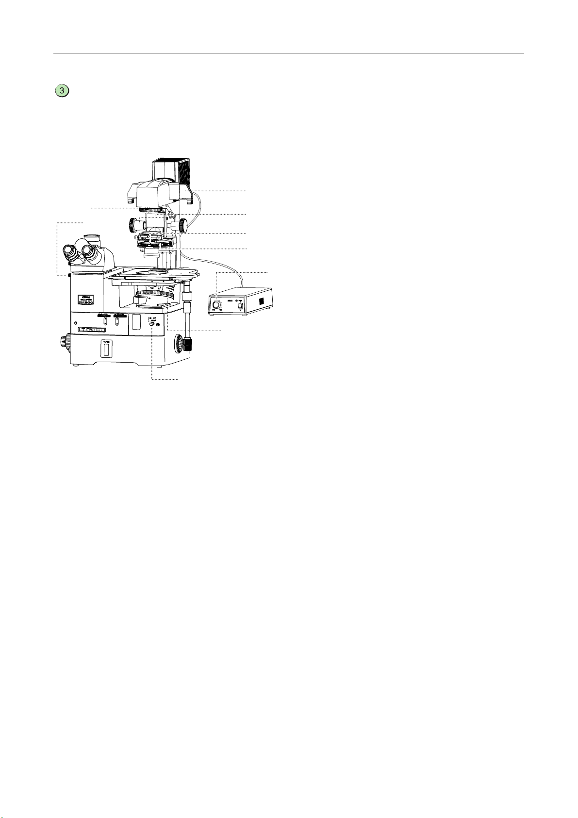
Set the microscope for the polarization microscopy under the episcopic illumination.
1 Turn the revolving nosepiece to place the
objective of a desired magnification into the optical
path. (See 3.9.2.)
2 Push in the polarizer/analyzer unit to the second
click-stop position and place it into the optical
path. (See 3.13.1.)
3 Turn the polarizer rotation ring to the crossed
Nicol’s position. (See 3.13.2.)
4 To perform the sensitive color polarization
microscopy, insert the λplate into the
polarizer/analyzer unit and place it into the optical
path. (See 3.14.1.)
5 Turn the brightness control dial to adjust the
brightness of the episcopic illumination. (See
3.2.1.)
6 Adjust the brightness with the desired ND filter in
the filter turret. (See 3.10.)
7 Turn the polarizer rotation ring to adjust the
polarization while observing the image.
3-6
3-5
3-4
3-3, 7 3-2
3-1
Return to the bright-field microscopy under the episcopic illumination.
1 Pull the analyzer/polarizer unit to the first
click-stop position to remove the
analyzer/polarizer from the optical path. (See
3.13.1.)
2 Both the λplate and the polarizer/analyzer unit are
removed from the optical path. (See 3.14.1.)
3 Turn the brightness control dial to adjust the
brightness of the episcopic illumination. (See
3.2.1.)
4 Adjust the brightness with the desired ND filter in
the filter turret. (See 3.10.)
20
Chapter 2 Microscopy
2.4
Differential Interference Contrast Microscopy under the Episcopic Illumination
Attach the items required for the differential interference contrast (DIC) microscopy
under the episcopic illumination to the microscope. (See Table 2.1.)
Focus on the sample with the bright-field microscopy under the episcopic illumination.
(See Pages 16 and 17.)
Set the microscope for the DIC microscopy under the episcopic illumination.
3-7
3-6
3-5
3-3, 5
3-4
3-2
3-1
1 Turn the revolving nosepiece to place the
objective of a desired magnification into the optical
path. (See 3.9.2.)
2 Push in the polarizer/analyzer unit to the second
click-stop position and place it into the optical
path. (See 3.13.1.)
3 Turn the polarizer rotation ring to the crossed
Nicol’s position (See 3.13.2.)
4 Attach the DIC slider to the slot on the revolving
nosepiece to place the DIC prism into the optical
path. (See 3.15.1 or 3.16.2.)
5 Set the interference color. (See 3.15.3 or 3.16.3.)
For using the L-DIHC/L-DIC slider, turn the prism
movement knob, whereas for using the
LV-DIHC/LV-DIC slider, turn the polarizer rotation
ring of the polarizer/analyzer unit. In either case,
the interference color changes continuously from
dark color, gray to sensitive red-violet.
6 Turn the brightness control dial to adjust the
brightness of the episcopic illumination. (See
3.2.1.)
7 Adjust the brightness with the desired ND filter in
the filter turret. (See 3.10.)
■ Sensitive color microscopy
You can perform the sensitive color DIC microscopy using the λ plate placed into the polarizer/analyzer unit.
If the λ plate is placed into the optical path in the crossed Nicol’s position (on dark background), the
background is set to sensitive red-violet. This improves the contrast of the image to the highest degree. If you
turn the polarizer rotation ring to pale-blue for background change when the λ plate is inserted, the
interference image will resemble the dark contrast image in the phase contrast microscopy. Select the
background color to achieve the desired contrast, if the phase contrast ratio varies intensively (for the rough,
uneven surface of sample).
21

Chapter 2 Microscopy
Return to the bright-field microscopy under the episcopic illumination.
1 Pull the polarizer/analyzer unit to the first
stop-click position and remove the
polarizer/analyzer from the optical path. (See
3.13.1.)
2 Both the λplate and the polarizer/analyzer unit are
removed from the optical path. (See 3.14.1.)
3 Detach the DIC slider to remove the DIC prism
from the optical path. (See 3.15.1 or 3.16.2.)
4 Turn the brightness control dial to adjust the
brightness of the episcopic illumination. (See
3.2.1.)
5 Adjust the brightness with the desired ND filter in
the filter turret. (See 3.10.)
2.5 Epi-fl Microscopy
Attach the items required for the epi-fl microscopy to the microscope. (See Table 2.1.)
To perform the epi-fl microscopy using the C-HGFI/C-HGFIE HG Precentered Fiber Illuminator as the
external light source, screw the compensation filter supplied with the fiber adapter into the MA2-FL
fluorescent unit. (Refer to 4.15.1.)
Find the target and focus on the sample by BF/DF microscopy under the episcopic
illumination. (See Pages 16 to 17, and 19.)
Set the microscope for the epi-fl microscopy.
1 Turn the revolving nosepiece to place the
objective of a desired magnification into the optical
path. (See 3.9.2.)
2 Turn the BD field changeover lever to the “BF
(bright-field)” position. (See 3.3.)
3 Push the attached fluorescent unit into the second
click-stop position and place the fl filter into the
optical path (See 3.19.1.)
4 Turn the brightness control dial to adjust the
brightness. (See 3.2.1.)
5 Adjust the brightness with the desired ND filter in
the filter turret. (See 3.10.)
3-5
3-4
3-3
3-1
3-2
22

Chapter 2 Microscopy
Return to the bright-field or dark-field microscopy under the episcopic illumination.
1 Turn the BD field changeover lever to the “BF
(bright-field)” or “DF (dark-field)” position. (See
3.3.)
2 Turn the brightness control dial to adjust the
brightness. (See 3.2.1.)
3 Adjust the brightness with the desired ND filter in
the filter turret. (See 3.10.)
23
Chapter 2 Microscopy
2.6 Bright-field Microscopy under the Diascopic Illumination
Attach the items required for the bright-field microscopy under the diascopic illumination.
(See Table 2.1.)
Turn on the power to light up the diascopic illumination lamp. (See 3.23.1.)
1 Set the brightness control dial to OFF on the
MA200 main body. (See 3.2.1.)
2 Turn on the TI-PS100W power supply connected
to the supporting pillar for dia-Illuminator.
3 Set the MA200 main body to ON.
The power LED on the front is lit.
2-4
2-2
The light intensity control dial for the TI-PS100W
power supply is enabled.
4 Turn the light intensity control dial on the
TI-PS100W power supply to adjust the
illumination.
You can change the output voltage within 1V to
12V. When the output voltage is set to around 9V,
the ideal optical color reproduction generates.
2-3
2-3
2-1
24
Chapter 2 Microscopy
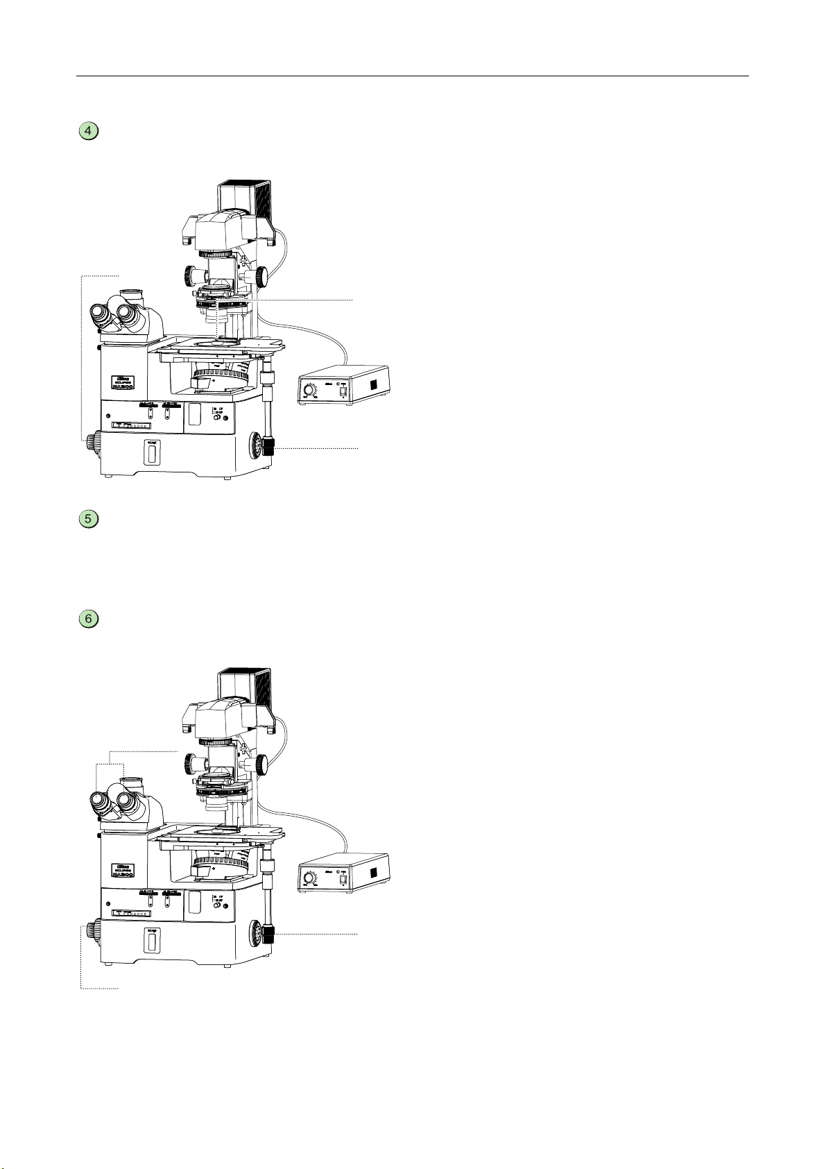
Set the microscope for the bright-field microscopy under the diascopic illumination.
When the “Other items required” (See the column at the right edge of Table 2.1.) is used for the episcopic
illumination, remove each attachment from the optical path in advance.
3-1
3-6
3-4, 5
3-8
3-7
3-9
3-5
3-3
3-2
1 Push in the optical path changeover lever for the
eyepiece tube and select 100% for the binocular
eyepiece. (See 3.4.1.)
2 Push in the BD field changeover lever to select the
“BF (bright-field)” position. (See 3.3.)
3 Turn the revolving nosepiece to place the 10X
objective into the optical path. (See 3.9.2.)
4 Place the NCB filter on the supporting pillar for
dia-Illuminator into the optical path and
compensate the color temperature. (See 3.23.5.)
5 Adjust the brightness of the diascopic illumination
roughly with the light intensity control dial for the
TI-PS100W power supply and the desired ND filter
on the pillar illuminator. (See 3.23.1 and 3.23.5.)
6 Turn the field diaphragm dial for the supporting
pillar for dia-Illuminator clockwise to the limit and
fully open the field diaphragm for the diascopic
illumination. (See 3.23.3.)
7 Turn the aperture diaphragm lever for the system
condenser clockwise to the limit and fully open the
field diaphragm. (See 3.23.4)
8 Turn the condenser focus knobs for the supporting
pillar for dia-Illuminator and lower the condenser
mount to the limit. (See 3.23.6.)
• When the ELWD condenser lens is attached to
the system condenser, lower the condenser
mount approximately 1 cm from the upper limit.
• When the ELWD-S condenser is used, lower
the condenser mount approximately 2 cm from
the upper limit.
9 Turn the turret of the condenser to the “A” position
to place the bright-field condenser cassette into
the optical path.
25
Chapter 2 Microscopy
Place the sample onto the stage to adjust the focus.
4-2
4-1
4-1
1 Use the sample holder according to the selected
2 Turn the coarse/fine focus knobs and focus on the
Adjust the diopter and the interpupillary distance.
1 Adjust the interpupillary distance. (See 3.5.)
2 Adjust the diopter. (See 3.6.)
sample. Place the sample onto the stage and
move the stage using the stage movement knob
for the X/Y direction so that the observation
position comes to the center of the view-field. (See
3.8.)
sample. (See 3.7.)
Adjust the focus again.
6-1, 2
6-2
6-1
1 Look into the eyepieces. Move the stage to bring
the observation target into the center of the
view-field using the stage movement knob for the
X/Y direction.
2 Look into the eyepieces. Adjust the focus onto the
sample by turning the coarse/fine focus knob.
26
Chapter 2 Microscopy
Center the condenser. (See 3.23.2.)
7-2, 6
7-1, 5
7-3
7-4, 7
1 Be sure that the objective is set to the 10X
objective.
If not, turn the revolving nosepiece to place the 10X
objective into optical path.
2 Stop down the field diaphragm by turning the field
diaphragm dial on the supporting pillar for
dia-Illuminator until the field diaphragm image
comes into the view-field.
3 Turn the condenser focus knob for the supporting
pillar for dia-Illuminator to focus on the field
diaphragm image.
4 Turn the two condenser centering screws for the
pillar illuminator to move the field diaphragm
images to the center of the view-field.
5 Turn the revolving nosepiece to place the 40X
objective into the optical path.
6 Turn the field diaphragm dial for the supporting
pillar for dia-Illuminator until the diaphragm image
becomes nearly the same as the view-field.
7 Turn the two condenser centering screws on the
supporting pillar for dia-Illuminator to move the field
diaphragm images to the center of the view-field.
Set the desired magnification and observe the sample.
8-5
8-3
8-1
8-6
Note: Condenser refocusing clamp (See 3.23.6.)
To raise or lower the condenser, secure the clamp in advance. You can restore the condenser position
8-4
8-2
8-4
8-5
easily.
1 Turn the revolving nosepiece to place the objective
of a desired magnification into the optical path.
2 Move the aperture diaphragm lever on the system
condenser to adjust the aperture diaphragm to a
size of 70 to 80% of the objective N.A. (See
3.23.4.)
3 Turn the field diaphragm dial for the supporting
pillar for dia-Illuminator until the diaphragm
becomes nearly the same as the view-field. (See
3.23.3.)
4 Push in or pull out the desired ND filter on the
supporting pillar for dia-Illuminator to place it into
the optical path, then adjust the brightness for the
view-field. (See 3.23.5.)
If accurate color reproduction is not crucial (e.g., for
color photography), change the lamp voltage with
the light intensity control dial on the TI-PS100W
power supply.
5 Look into the eyepieces. Move the stage to bring
the observation target into the center of the
view-field.
6 Turn the coarse/fine focus knobs and focus on the
sample.
27
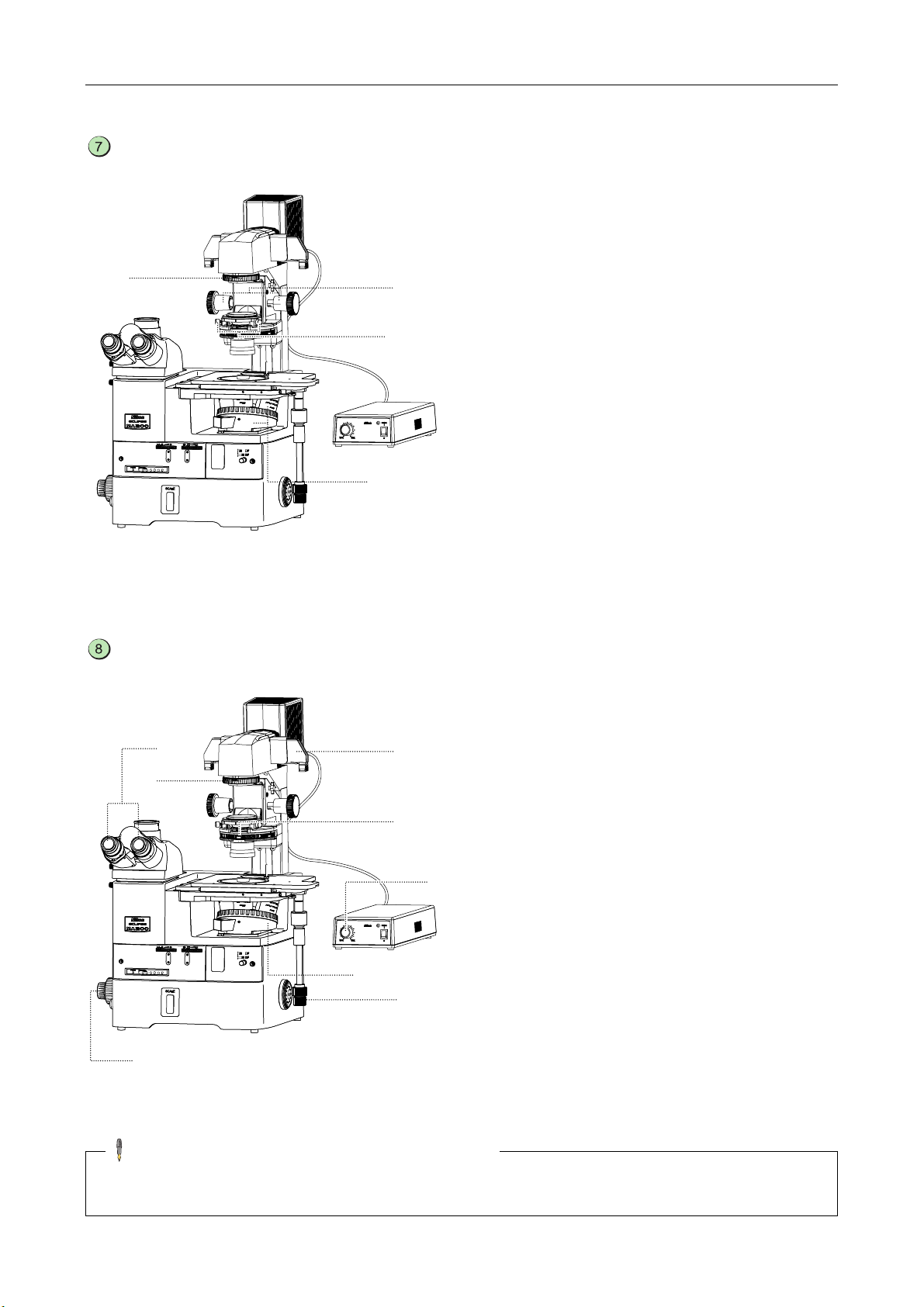
Chapter 2 Microscopy
2.7
Polarization Microscopy under the Diascopic Illumination (simplified/sensitive color)
Attach the items required for the polarization microscopy under the diascopic
illumination to the microscope. (See Table 2.1.)
Focus on the sample with the bright-field microscopy under the diascopic illumination
and center the condenser. (See pages 23 to 26.)
Set the microscope for the polarization microscopy under the diascopic illumination.
1 Turn the revolving nosepiece to place the
objective of a desired magnification into the optical
3-6
3-3, 4
3-5
3-1
3-2
path. (See 3.9.2.)
2 Push the polarizer/analyzer unit attached to the
MA200 main body into the optical path. (See
3.13.1.)
When using the sextuple revolving nosepiece,
insert the D-DA analyzer slider into the slot on the
revolving nosepiece instead of the
polarizer/analyzer unit, if desired. (See 3.17.1.)
3 Place the T-P2 polarizer into the optical path and
make a crossed Nicol’s position. (See 3.23.8.)
4 To perform the sensitive color polarization
microscopy, place the TI-DIC λplate into the
optical path. (See 3.23.8.)
When using the sextuple revolving nosepiece, use
the D-LP λplate instead of the TI-DIC λplate, if
desired. (See 3.18.1.)
5 Turn the light intensity control dial on the TI-PS
100W power supply to adjust the brightness of the
diascopic illumination.
6 Push in or pull out the desired ND field for the
supporting pillar for dia-Illuminator to place it into
the optical path, then adjust the brightness for the
view-field. (See 3.23.5.)
Return to the bright-field microscopy under the diascopic illumination.
1 Remove the analyzer from the optical path.
2 Remove both the T-P2 polarizer and the λplate
from the optical path.
3 Turn the light intensity control dial on the TI-PS
100W power supply to adjust the brightness of the
diascopic illumination.
4 Push in or pull out the desired ND field for the
supporting pillar for dia-Illuminator to place it into
the optical path, then adjust the brightness for the
view-field.
28
 Loading...