

Nikon Eclipse LV100POL Instructions Manual

M357 E 05.9.NF.1
Polarizing Microscope
ECLIPSE LV100POL
Instructions

Thank you for purchasing the Nikon product.
This instruction manual is written for the users of the Nikon Microscope ECLIPSE
LV100POL.
To ensure correct usage, please read this manual carefully before operating the product.
• It is prohibited to reproduce or transmit this manual in part or whole without Nikon’s
expressed permission.
• The contents of this manual are subject to change without notice.
• Every effort has been made to ensure the accuracy of this manual. If you find that any
portion of this manual is unclear or incorrect, please contact your nearest Nikon
representative.
• Some of the products described in this manual may not be included in the set you have
purchased.
• Also be sure to read the manuals for any other products that you are using with this system.
WARNING and CAUTION Symbols
Although Nikon products are designed to provide the utmost safety during use, incorrect usage
or failure to follow the safety instructions provided may cause personal injury or property
damage. To ensure correct usage, read the instruction manual carefully and thoroughly before
using the product. Do not discard the manual; keep it handy for easy reference.
Safety instructions within this manual are accompanied by the following symbols to highlight
their importance. For your safety, always follow the instructions accompanying these symbols.
Symbol Meaning
WARNING
CAUTION
Disregarding instructions accompanying this symbol may lead to
serious injury or death.
Disregarding instructions accompanying this symbol may lead to
injury or property damage.
Meaning of the symbol used on the product
The symbol appearing on the product indicates the need for caution at all times during use.
Always refer to the instruction manual and read the relevant instructions before manipulating
any part to which the symbol has been affixed.
Symbol Meaning
Caution for heat
This marking on the back of the lamp house and near the lamp
house clamp screw of the LV-UEPI Universal Epi Illuminator calls
your attention on the following: You can see the positions of this
symbol on Page 10 and 11.
• The lamp house become extremely hot while the lamp is on and
immediately after it is turned off.
• Do not touch the lamp house during and immediately after
lighting to prevent the risk of burns.
• Make sure that the lamp house is sufficiently cool before the
lamp replacement.
1

WARNING
1. Intended product use
This microscope is intended primarily for microscopy and photomicrography of stones,
rocks, minerals, and high-polymer materials using a polarized light illumination. Besides,
this microscope is intended for use in optical property analysis in the fields of mineralogy
and high polymer chemistry.
2. Do not disassemble
Disassembling this product may result in electric shock or malfunctions. Damage or injury
that may occur due to mishandling is unwarranted. Never attempt to disassemble any part
other than the parts described in this manual. If you experience problems with the product,
contact your nearest Nikon representative.
3. Read the instructions carefully
To ensure safety, carefully read this manual and the manuals provided with any other
equipment used with this product. In particular, observe all warnings and cautions given at
the beginning of each manual.
To use an external light source
When an external light source, such as a mercury lamp or a xenon lamp, is used, you must
take great care of the lamp. Read the instruction manual for the light source and follow the
instructions and cautions for it.
4. Rated voltage
The power supply circuit in this product is designed for AC power of 100 to 240 VAC and
50/60 Hz. Before connecting the power cord, check that the power supply to be used
conforms to the voltage and frequency described above. Use of a non-conforming power
supply may result in equipment malfunction, failure, or fire.
5. Power cord
Be sure to use the specified power cord. Using a wrong power cord may result in
malfunctions or fire. The product is classified as subject to Class I protection against
electrical shock. Make sure it is connected to an appropriate ground terminal (protective
earth terminal). To prevent electrical shock, always turn off the power switch (press it to the
“ ” position) on the power supply before attaching or detaching the power cord. For
specifications of the power cord, refer to “VII. Specifications.”
6. Specified light source
Use this product with a specified light source. The specified light source devices are as
follows:
• Episcopic illuminator
Nikon LV-UEPI Universal Epi Illuminator (model name: LV-UEPI)
• Lamp house (for episcopic illumination and diascopic illumination)
Nikon LV-LH50PC Precentered Lamp House 12V 50W (model name: LV-LH50PC)
• Lamp
Nikon LV-HL50W 12V 50W LONGLIFE halogen lamp (model name: LV-HL50W), or
non-Nikon 12V 50W SHORTLIFE halogen lamp (model name: OSRAM HLX 64610,
OSRAM HLX 64611, or PHILIPS 7027).
If you wish to buy these lamps, please contact your nearest Nikon representative.
Note that if a lamp not specified is used for this product, the product is not approved as a UL
listed product.
2
WARNING
7. Heat from the light source
The lamp and the lamp house become extremely hot. To avoid burns, do not touch the lamp
house while the lamp is lit or for thirty minutes after it is turned off. Furthermore, to avoid
the risk of fire, do not place fabric, paper, or highly flammable volatile materials (such as
gasoline, petroleum benzine, paint thinner, or alcohol) near the lamp house while the lamp is
lit or for about thirty minutes after it is turned off.
8. Air vents
Do not block the air vents on the microscope and lamp house. If the air vents are blocked,
the temperature of the microscope will raise. And it results in damage or fire.
9. Reflection
Lustrous samples reflect the illumination. Do not observe the illuminated surface of a
sample for a long time because the strong reflection may hurt your eyes.
3

CAUTION
1. Handle with care
2. Do not wet the microscope
3. Weak electromagnetic waves
4. Installation location
This product is a precision optical instrument. Handle the product with care to avoid shock
on impact.
In particular, objectives may loose accuracy when exposed to even a weak physical shock.
If the microscope gets wet, a short circuit may cause malfunction or abnormal heating of the
microscope. If you accidentally spill water on the microscope, immediately turn off the
power switch (flip it to the “ ” side) and unplug the power cord from the wall outlet. Then,
wipe off the water with a piece of dry cloth. If water enters a component, immediately
suspend use of this product, disconnect the power cord from the outlet, and contact your
nearest Nikon representative.
The product emits weak electromagnetic waves. There is a possibility that some precision
electronic devices are affected by the electromagnetic waves. To prevent bad influences,
locate such electronic devices away from the microscope system. If a TV or radio reception
is affected, move the TV or radio set farther from the product.
This microscope system is a precision optical instrument. The usage or storage in an
inappropriate environment may result in malfunctions or poor performance.
Consider the following factors when selecting an installation location:
• Avoid a brightly lit location, such as exposed to direct sunlight or directly under a room
light. The image quality deteriorates if there is excessive ambient light.
• Always install the microscope with a surrounding clear area of 10 cm or more.
• Choose a location that is free from considerable dust or dirt.
• Choose a flat surface with little vibration.
• Choose a sturdy desk or table for the base of the microscopy system.
• Do not install the microscope in a hot and humid location.
• Select a layout that allows easy removal of the power cord from the product’s AC inlet in
the event of an emergency.
• For details about the operating environment and storage environment, see “VII.
Specifications.”
5. Cautions on moving the microscope
• This product is a precision optical instrument. Handle it carefully and do not subject it to a
strong physical shock. (In particular, objectives may loose accuracy when exposed to even
a weak physical shock.)
• When moving the microscope, first remove the lamp house. Then, securely hold the
microscope by the root of the arm from the back.
(Information) The microscope with the stage, eyepiece tube, lamp house, and other parts
attached, weighs approx. 20 kg.
• Do not hold the focus knobs, eyepiece tube, lamp house, sub-stage, or so on, when
carrying the microscope. They may come off and may cause serious injury or malfunction.
• Be careful not to pinch your hands or fingers when setting up the microscope.
6. Cautions on assembling the microscope
• Be careful not to pinch your fingers or hands during assembly.
• Scratches or fingerprints on the lenses will adversely affect the image. Be careful not to
scratch or touch the lens surfaces.
4
CAUTION
7. Cautions on lamp replacement
• To prevent burn injuries, wait at least 30 minutes after the lamp is turned off to give it
sufficient time to cool when replacing lamps.
• To prevent electrical shock and damage to the microscope, always turn off the power
switch (flip it to the “
or detaching the lamp house.
• Never touch the glass surface of the lamp with bare hands. Doing so will cause
fingerprints, grease, etc. to burn onto the lamp surface, reducing the illumination. If you
do get any fingerprints or dirt on the lamp, wipe them clean.
• Make sure the lamp house cover is securely fitted to the lamp house after replacing lamps.
Never turn on the lamp with the lamp house cover removed.
• When you dispose of the replaced lamp, do not break it up. Instead, dispose of the used
lamp as special industrial waste or dispose of it according to the local regulations and
rules.
” side) and unplug the power cord from the outlet before attaching
5
CONTENTS
WARNING and CAUTION Symbols .................................................................... 1
Meaning of the symbol used on the product ................................................... 1
WARNING ........................................................................................................ 2
CAUTION.......................................................................................................... 4
Part Names ................................................................................................... 8
1 Components and Controls ................................................................................................. 8
2LV100POL with Epi Illuminator ..................................................................................... 10
3Rear View ........................................................................................................................ 11
Microscopy................................................................................................. 12
1 Diascopic Bright-field Microscopy ................................................................................. 12
2 Orthoscopic Observation ................................................................................................. 16
3 Conoscopic Observation.................................................................................................. 17
4 Episcopic Microscopy (with the Epi Illuminator Option) ............................................... 18
5 Photomicroscopy ............................................................................................................. 21
Operation of Each Part.............................................................................. 22
1Power ON / OFF.............................................................................................................. 22
2 Operation for the Illumination......................................................................................... 23
3Filter Operation ...............................................................................................................24
4 Coarse Focus Knob / Fine Focus Knob Operation .......................................................... 25
5Stage Rotation .................................................................................................................26
6Trinocular Eyepiece Tube Operation............................................................................... 27
7 Diopter Adjustment ......................................................................................................... 28
8 Interpupillary Distance Adjustment ................................................................................ 28
9 Condenser Operation ....................................................................................................... 29
10 Focusing and Centering the Condenser........................................................................... 30
11 Adjusting the Aperture Diaphragm ................................................................................. 30
12 Adjusting the Field Diaphragm ....................................................................................... 32
13 Filter on the Field Lens ................................................................................................... 32
14 Centering the Objective ................................................................................................... 33
15 Oil Immersion Operation ................................................................................................ 34
16 Water Immersion Operation ............................................................................................ 35
17 Operation of the Polarizers.............................................................................................. 36
18 Operation of the Analyzer ............................................................................................... 37
19 Azimuth Adjustment of the Polarizer and Analyzer........................................................ 38
20 Bertrand Lens Operation ................................................................................................. 39
21 Operation of Examination Plates..................................................................................... 40
22 Episcopic Microscopy ..................................................................................................... 42
23 Image Capturing .............................................................................................................. 45
6
Assembly.................................................................................................... 46
1 Attaching the Circular Graduated Stage.......................................................................... 48
2Attaching the Condenser ................................................................................................. 48
3 Attaching the Nosepiece.................................................................................................. 49
4 Attaching Objectives ....................................................................................................... 49
5 Attaching the Epi Illuminator (for the Episcopic Microscopy)....................................... 50
6 Attaching the Lamp House and Replacing Lamps .......................................................... 51
7 Attaching the Polarizing Intermediate Tube .................................................................... 53
8 Attaching the Eyepiece Tube ........................................................................................... 53
9 Attaching Eyepieces ........................................................................................................ 53
10 Attaching a Camera (for the Trinocular Eyepiece Tube) ................................................ 54
11 Attaching Eye Level Risers ............................................................................................. 54
12 Connecting the Power Cord ............................................................................................ 55
Troubleshooting ......................................................................................... 56
1Viewing Problems and Control Problems ....................................................................... 56
2 Electrical System Problems ............................................................................................. 59
Care and Maintenance .............................................................................. 60
1 Cleaning Lenses and Filters ............................................................................................ 61
2 Cleaning the Painted, Plastic, and Printed Parts.............................................................. 61
3 Storage ............................................................................................................................. 61
4Regular Inspection........................................................................................................... 61
Specifications ............................................................................................ 62
7
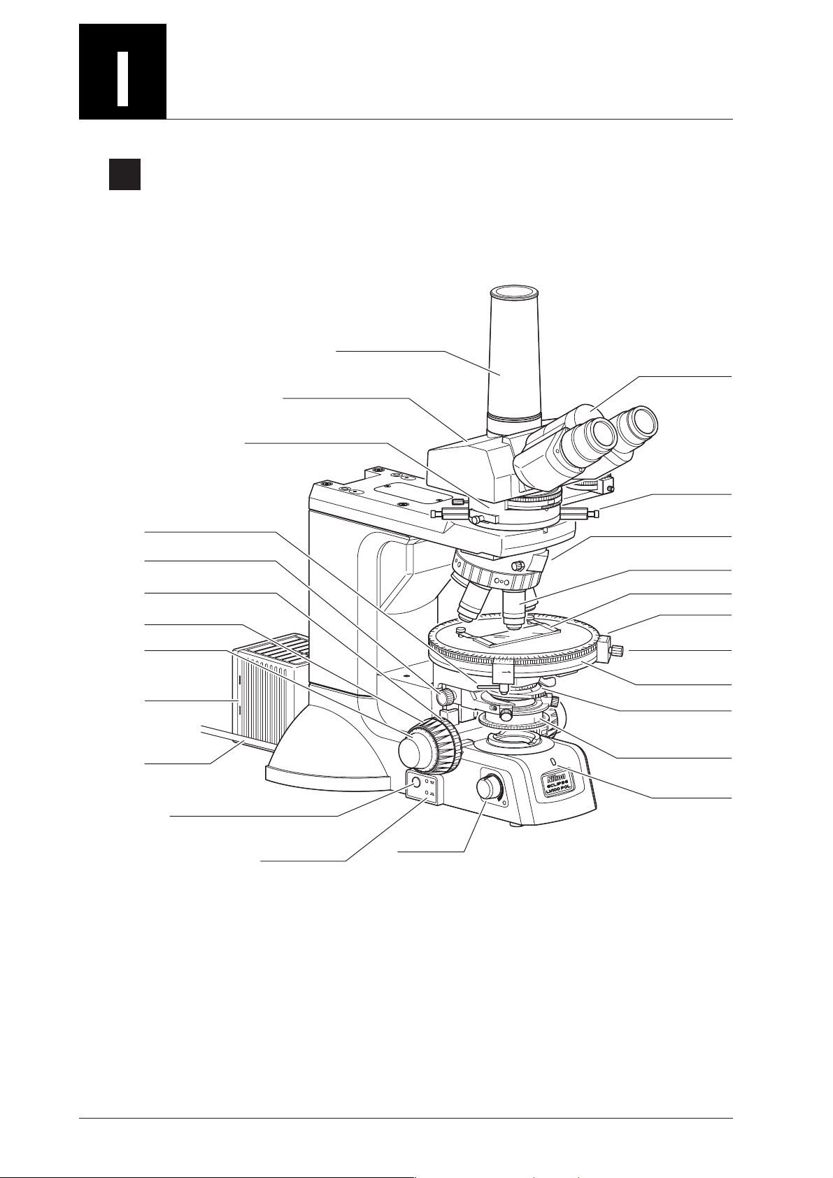
Part Names
1
Components and Controls
The figures in this section show the ECLIPSE LV100POL microscope with the diascopic
illumination lamp house, the trinocular eyepiece tube, the vertical tube adapter, and the P swing-out
condenser.
Tr inocular eyepiece tube
Polarizing intermediate tube
Ver tical tube adapter
Binocular section
45° click-stop lever
Condensor focus knob
Coarse torque
adjustment ring
(TORQUE)
Coarse focus knob
Fine focus knob
Diascopic
illumination
lamp house
Power cable
Epi/dia selection switch
(Selection switch between episcopic
illumination and diascopic illumination)
Epi/dia indicator
EPI/DIA
Brightness
control knob
P-CL 1/4 λ &
tint plate
0
*1
Nosepiece
(quintuple centering nosepiece)
Objective
Specimen holder
*2
Ver nier
Stage rotation
clamp screw
O
N
CL
I
CK
N
A
P
JA
90
0.
2
0.
chr
A
0.4
0.6
8
0.
Circular graduated
stage
Condenser
(P swing-out condenser)
Polarizer for the
diascopic microscopy
(placed in the polarizer
OFF
rotation ring)
Power indicator
*1: This part can be changed to the optional P-CS Senarmont
compensator or P-CQ quartz wedge.
*2: This part is removed to install the optional attachable
mechanical stage.
8
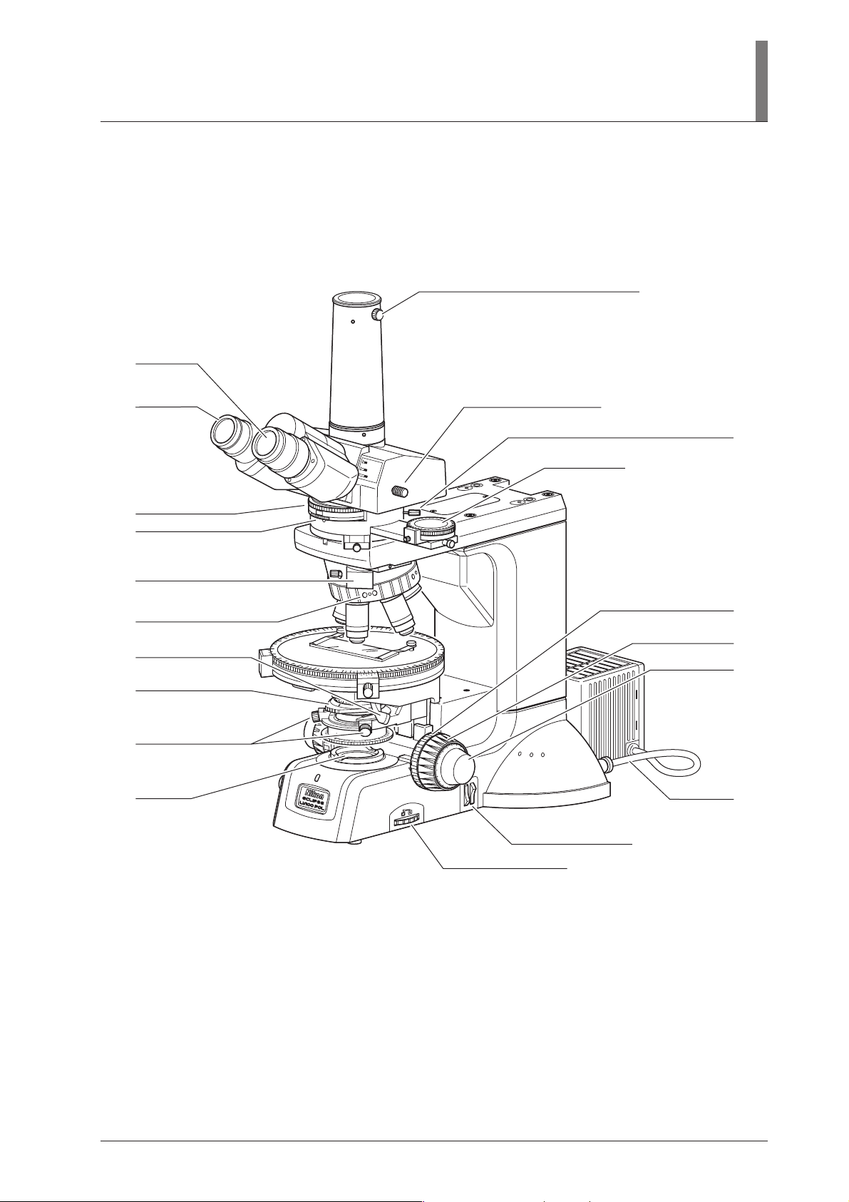
Eyepiece
Diopter
adjustment
ring
I. Part Names
Photomicrographic equipment clamp screw
Optical path selector lever
Bertrand lens centering screws (both sides)
Bertrand lens turret
Bertrand lens focus ring
Slot (20 x 6 mm)
Used for parts available on the market
such as a compensator or so on.
Objective centering screws
Swing-out lever for the
condenser top lens
Condenser aperture
diaphragm ring
Condenser centering
screws
Field lens
B
I
N
O
B
IN
O
&
P
H
O
T
O
P
H
OT
O
0
Analyzer slider
Coarse focus stopper ring
(CLAMP)
Coarse focus knob
Fine focus knob
A
chr
0.
8
0.
90
JA
PA
N
0
.
6
0
.
4
0.2
CB
N
ND8
.S.
F
Lamp cable
Filter selector switches
Field diaphragm control
9
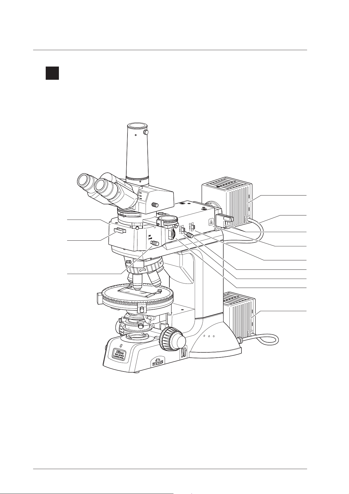
2
LV100POL with Epi Illuminator
The figure in this section shows the ECLIPSE LV100POL microscope with the epi illuminator, the
episcopic illumination lamp house, the diascopic illumination lamp house, the trinocular eyepiece
tube, the vertical tube adapter, and the P swing-out condenser.
Epi illuminator
(LV-UEPI)
Dummy slider
Bright-field/dark-field
illumination selector lever
Episcopic illumination
B
I
N
O
B
IN
O
&
P
H
OTO
P
H
OTO
0
P
TO
S
.
A
P
STO
.
F
lamp house
Lamp cable
Filter sliders
BF
DF
“CAUTION for
heat” symbol
Aperture diaphragm
open/close lever
Field diaphragm centering screw
Field diaphragm open/close lever
Polarizer slider *
Diascopic illumination
A
chr
0.
8
0.
90
J
AP
A
N
0
.6
0
.
4
0.
2
CB
N
ND8
lamp house
10
.S.
F
*: This part is used to perform the episcopic polarization
microscopy.
3
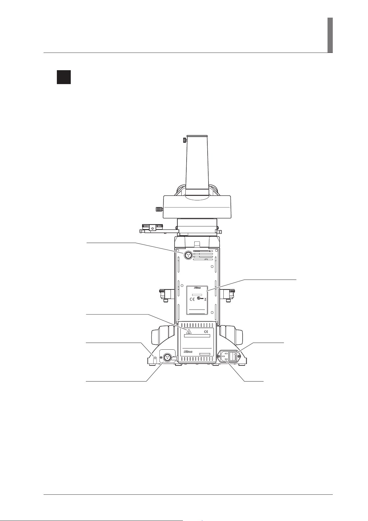
Rear View
I. Part Names
The figure below shows the ECLIPSE LV100POL microscope with the diascopic illumination lamp
house, the trinocular eyepiece tube, and the vertical tube adapter.
Connector for the
episcopic illumination
lamp house
“CAUTION for heat” symbol
Connector for the diascopic
illumination lamp house
LAMP
DC12V 50W
LAMP
DC12V 50W
ECLIPSE LV100POL
100–240V~ 1.2A 50/60Hz
MADE IN JAPAN
850001
4N75
INSPECTION
EQUIPMENT
including interference that may cause
undesired operation.
This Class A digital apparatus complies with
Canadian ICES-003.
Cet appareil numérique de la classe A est
confirme à la norme NMB-003 du Canada.
- High Temperature -
CAUTION !
1.
Do not touch the lamphouse while the lamp is lit.
The surface of the lamphouse becomes hot when
the lamp is on.
2.
Turn off the power and allow the lamp and lamphouse to cool enough before replacing the lamp.
Wait for at least 30 minutes after turning off
the lamp
Use 12V50W HALOGEN lamp only.
3.
HALOGEN 12V50W
LV-LH50PC
JAPAN
652702
Input voltage indication
Power switchGround terminal (M4)
AC inlet
11
Microscopy
0
0
0
This chapter explains microscopy procedures with the LV100POL microscope.
• For detailed information about operations of parts of the microscope, refer to Page 22, “III. Operation of
Each Part.”
• If the microscope is not assembled yet, refer to Page 46, “IV. Assembly” and assemble the microscope
before hand.
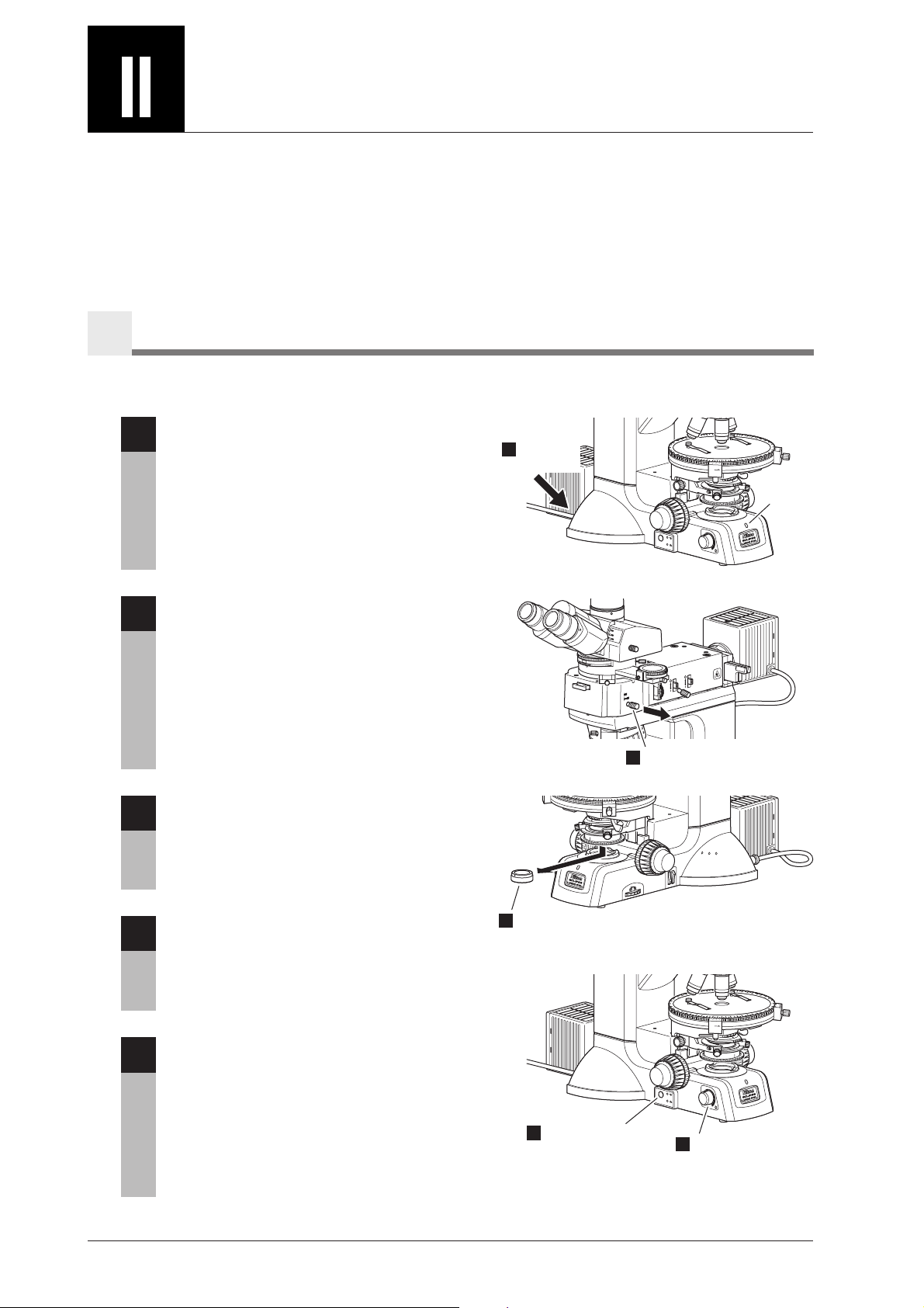
Diascopic Bright-field Microscopy
1
This section describes the diascopic bright-field microscopy using the diascopic illumination lamp.
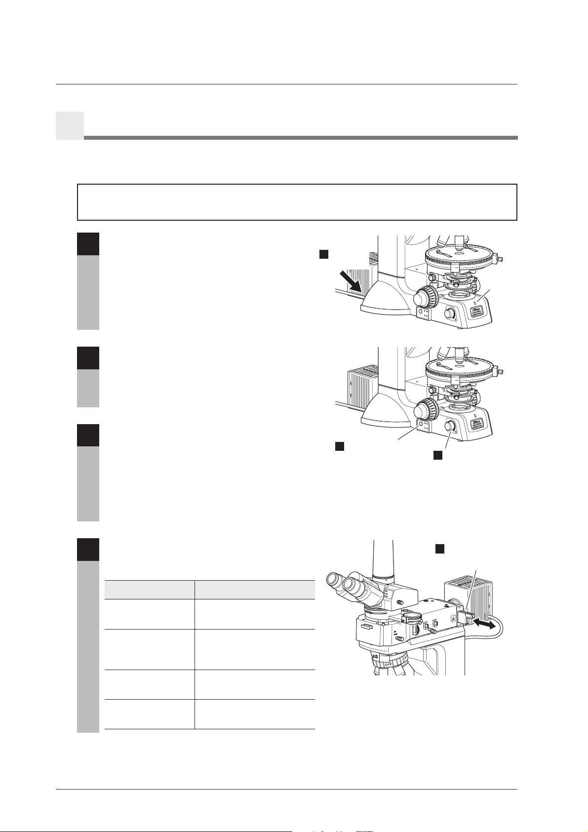
Turn on the power switch.
1
When the microscope power is turned on, the
power indicator on the microscope base is lit.
See Page 22.
1
Tu r n on
the power.
ON
CL
ICK
8
0.
EP
I/D
IA
OFF
N
A
P
A
J
0
9
0.
2
r
h
0.
c
A
4
0.
0.6
Powe r
indicator
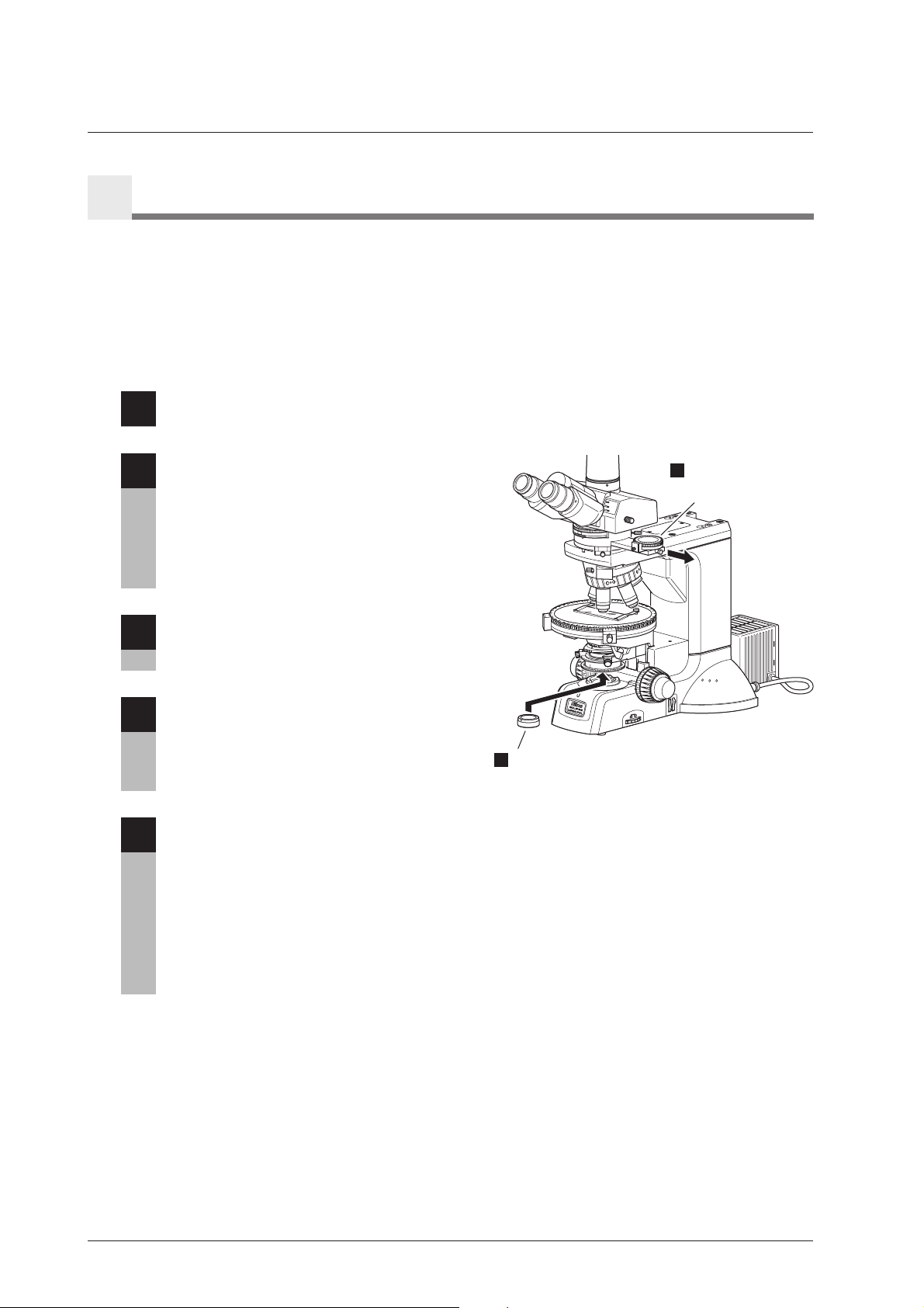
When the episcopic illuminator is attached,
2
pull out the illumination selector lever to
set the dark-field position (DF) for it.
See Page 42.
Remove the polarizer for the diascopic
3
microscopy.
BIN
O
BIN
O
&
PHOTO
PHO
T
O
0
BF
DF
2
A
chr
0
.
8
0
.
9
0
JAP
A
N
0.
6
0
.4
0
.
2
STOP
.
A
STOP
.
F
Select the dark-field (DF) side.
See Page 36.
NCB
ND8
F.S.
3
Push the epi/dia selection switch to select
4
the diascopic illumination. The indicator
Remove the polarizer for the diascopic microscopy.
for the diascopic illumination (lower side)
turns on.
See Page 23.
ON
CL
I
CK
N
A
P
A
J
0
9
0.
2
r
h
0.
c
A
4
0.
0.6
8
.
OFF
Adjust the
5
brightness.
0
Turn the brightness control knob to adjust
5
the brightness.
When the brightness control knob is turned, the
brightness of the illumination selected by the epi/
dia selection switch is changed.
See Page 23.
When the lamp lights, the power indicator on the
Select the diascopic
4
illumination. The
lower indicator lights.
EPI/DIA
microscope base lights green.
12
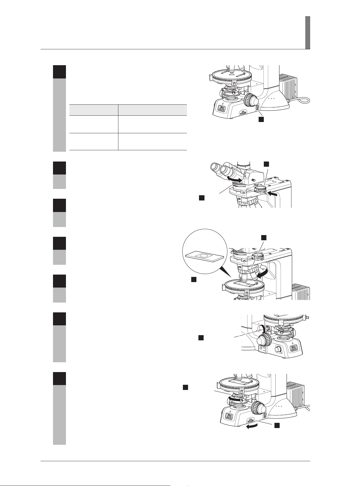
When necessary, push the filter selection
0
6
switches on the base of the microscope.
The NCB11 filter and ND8 filter can be
placed into the optical path.
See Page 24.
Filter type
NCB11
(color balancing filter)
Intended use
For color balance adjustment
and color photomicrography
II. Microscopy
A
chr
0
.
8
0
.
9
0
J
A
P
A
N
0
.
6
0
.4
0
.
2
B
NC
8
D
N
.
F.S
Set the appropriate
6
filter into the optical
path.
ND8
(ND filter)
For brightness adjustment
(transmittance 12.5%)
Push in the analyzer slider on the
7
polarizing intermediate tube to remove the
analyzer from the optical path.
See Page 37.
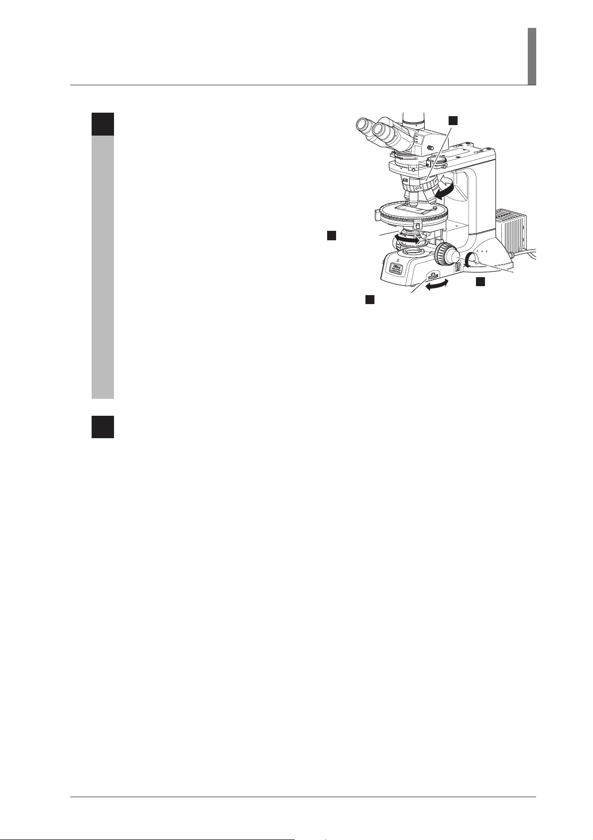
Move the Bertrand lens turret to the “0”
8
position to remove the Bertrand lens from
the optical path.
See Page 39.
Rotate the nosepiece to place the 10x
9
objective into the optical path.
The nosepiece must be stopped at the click stop
position.
Set the specimen in place with the cover
10
glass facing up.
Remove the
8
Bertrand lens
from the
optical path.
Cover glass
facing up
Set the
10
specimen.
Remove the
7
BINO
B
I
N
O
&
P
H
OTO
PHOTO
0
0
A
chr
0.
8
0
.
9
0
J
A
P
A
N
0.
6
0.4
0.
2
analyzer from
the optical path.
Set the 10x
9
objective.
Raise the condenser as high as it will go.
11
Raise the
11
condenser as
high as it will go.
E
P
I/D
ON
CLICK
N
A
P
A
J
90
.
0
0.2
Achr
0.4
0.6
0.8
IA
OF
F
Fully open the field diaphragm and the
12
condenser aperture diaphragm.
Fully open
12
the
condenser
aperture
Achr
0.8
0.90
J
A
P
A
N
0.6
0.4
0.2
diaphragm.
NCB
8
D
N
F.S.
Fully open
12
the field
diaphragm.
13
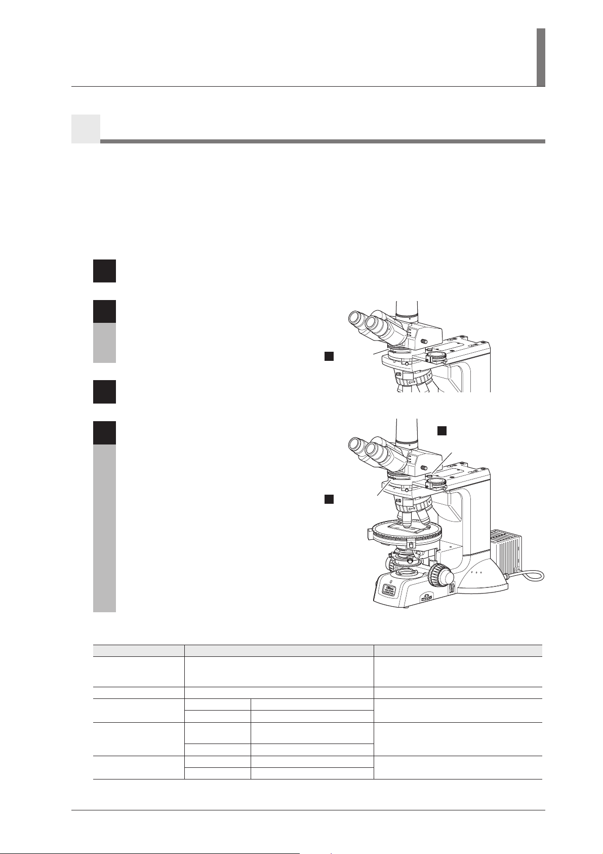
When using the trinocular eyepiece tube,
0
13
set the optical path selector lever to the
position where 100% light goes through
the binocular eyepiece.
See Page 27.
Set to the BINO
13
position.
BINO
B
I
N
O
&
P
H
OTO
PHOTO
0
Adjust the diopters and the interpupillary
14
distance.
See Page 28.
Focus on the specimen.
15
Fully loosen the coarse focus stopper ring.
See Page 25.
Center the objective.
16
See Page 33.
Adjust the diopters.
14
B
INO
B
I
N
O
&
P
H
OTO
PHOTO
0
Adjust the interpupillary distance.
14
A
chr
0
.
8
0
.
9
0
J
A
P
A
N
0.
6
0
.4
0
.
2
NCB
8
ND
F.S.
Loosen the coarse focus
15
stopper ring and focus on
the specimen.
0
Achr
0.8
0.90
J
A
P
A
N
0.6
0
.4
0.2
Centering the objective.
16
Focus and center the condenser.
17
See Page 30.
Focus the
17
condenser.
EPI/DIA
ON
CLICK
N
A
AP
J
0.90
0.2
chr
A
4
0.
.6
0
0.8
OFF
Centering the
17
condenser.
14
II. Microscopy
Rotate the nosepiece to locate the desired
18
magnification objective into the optical
path. Then, perform the microscopy.
• Each time you change objectives, the field
diaphragm and the condenser aperture
diaphragm must be adjusted.
- The field aperture should be adjusted so that
its image circumscribes the view field.
- And the aperture diaphragm should be 70% to
80% of the numerical aperture of the
objective.
See Pages 31 and 32.
• Focus on the specimen again using the fine focus
knob or the coarse focus knob.
See Page 25.
• The top lens of the swing-out condenser must be
operated depending on the magnification of the
objective to be used.
See Page 29.
• To use an oil immersion type objective or a
water immersion type objective, perform the oil
immersion or water immersion.
See Pages 34 and 35.
Adjust the
18
condenser
aperture
diaphragm.
0
Adjust the field
18
diaphragm.
Switch to any
18
8
D
N
.
F.S
desired objective.
B
NC
Readjust
18
the focus.
BI
NO
BI
NO
&
PH
OTO
PHOTO
A
chr
0
.
8
0
.
9
0
J
A
P
A
N
0.
6
0
.4
0
.
2
When the microscopy ends, turn off the power switch.
19
15
Orthoscopic Observation
2
This section describes the orthoscopic observation procedure. This observation method is the characteristic
method for polarizing microscopes. In this method, the specimen is observed with the polarizer and the
analyzer placed in the optical path.
The shape of the specimen in the direction of the optical axis and its optical properties in the direction of the
thickness can be observed. The vibration direction of the light and the property of the refraction can be
measured with observing light extinction or interference colors of specimens using the circular graduated stage.
Focus on the specimen with the diascopic bright-field microscopy. (Refer to Page 12,
1
“1. Diascopic Bright-field Microscopy.”)
Pull out the analyzer slider of the
2
polarizing intermediate tube to locate the
analyzer into the optical path.
Set the scale for the analyzer to the “0” position.
BINO
BI
N
O
&
PHOTO
PHOTO
0
Locate the
2
analyzer into
the optical path.
And, remove the Bertrand lens from the optical
path.
See Pages 37 and 39.
Set the polarizer for the diascopic
A
3
microscopy into the polarizer rotation ring.
chr
0
.
8
0
.
9
0
J
A
P
A
N
0.
6
0
.4
0
.
2
See Page 36.
B
NC
8
D
Adjust the orientation of the polarizer and
4
the analyzer.
N
.
F.S
See Page 38.
Set the polarizer.
After the adjustment, observe the specimen and
3
focus on it again.
Perform the orthoscopic microscopy.
5
• You can measure the retardation in various range with the P-CL 1/4 λ & tint plate.
See Page 40.
• The condenser aperture diaphragm and the field diaphragm must be adjusted in the same ways for the
bright-field microscopy.
See Pages 31 and 32.
• The top lens of the swing-out condenser must be operated depending on the magnification of the
objective to be used.
See Page 29.
16
II. Microscopy
Conoscopic Observation
3
This section describes the conoscopic observation procedure. This is the characteristic observation method of
polarizing microscopes. In this method, the specimen is observed with the polarizer, the analyzer, and the
Bertrand lens placed in the optical path.
The specimen can be observed from various angles with diascopic light in the form of a single image.
However, the shape of the specimen itself is not visible with this observation. You can distinguish the property
of the specimen between uniaxial and biaxial and can observe the optical axial angle and optical characteristics
of the specimen.
Perform the orthoscopic observation. (Refer to Page 16, “2 Orthoscopic Observation.”)
1
Rotate the Bertrand lens turret on the
2
polarizing intermediate tube to the “B”
position to locate the Bertrand lens into
the optical path.
See Page 39.
Set to the
2
“B” position.
BIN
O
B
IN
O
&
P
H
OTO
PHOTO
0
Focus and center the Bertrand lens.
3
See Page 39.
Perform the conoscopic microscopy.
4
• The P-CL 1/4 λ & tint plate is not used in this
microscopy. Move it to the vacant position.
• Select an objective having a large numerical
aperture (high magnification: normally 40x or
higher).
• The condenser aperture diaphragm should be
Focus the
3
Bertrand lens.
BINO
B
INO &
PH
O
T
O
PHOTO
0
Center the
3
Bertrand lens using
the two screws.
adjusted so that its image circumscribes the
conoscopic view field or should be fully opened.
• The field diaphragm should be adjusted so that
its image circumscribes the conoscopic view
A
chr
0
.
8
0
.
9
0
JA
P
AN
0.
6
0
.
4
0
.
2
field.
• The top lens of the P swing-out condenser must
be placed in the optical path.
B
NC
8
D
N
.
F.S
See Page 29.
The table below shows the settings for the orthoscopic microscopy and the conoscopic microscopy.
Observation purpose
Bertrand lens
Top lens of the P
swing-out condenser
Condenser aperture
diaphragm
Field diaphragm
Orthoscopic observation
Observation for light extinction or interference color
of the specimen to detect the vibration direction of
the light and the property of the double refraction.
OUT (“0” position)
10x or higher
4x or lower
10x or higher
4x or lower
10x or higher
4x or lower
70% to 80% of the numerical
aperture of the objective
Circumscribe the view field
IN
OUT
Fully open
Fully open
Observation for the property between uniaxial
Conoscopic observation
and biaxial and observation for the optical
axial angle and optical characteristics.
IN (“B” position)
IN
Circumscribe the conoscopic view field
(or fully open)
Circumscribe the conoscopic view field
17
Episcopic Microscopy (with the Epi Illuminator Option)
0
0
4
When the epi illuminator is attached, you can perform the episcopic microscopy with the episcopic
illumination lamp house.
Check the cumulative lit-on time of the lamp before the microscopy. If the cumulative lit-on time has
exceeded the average operation life, replace the lamp with new one.
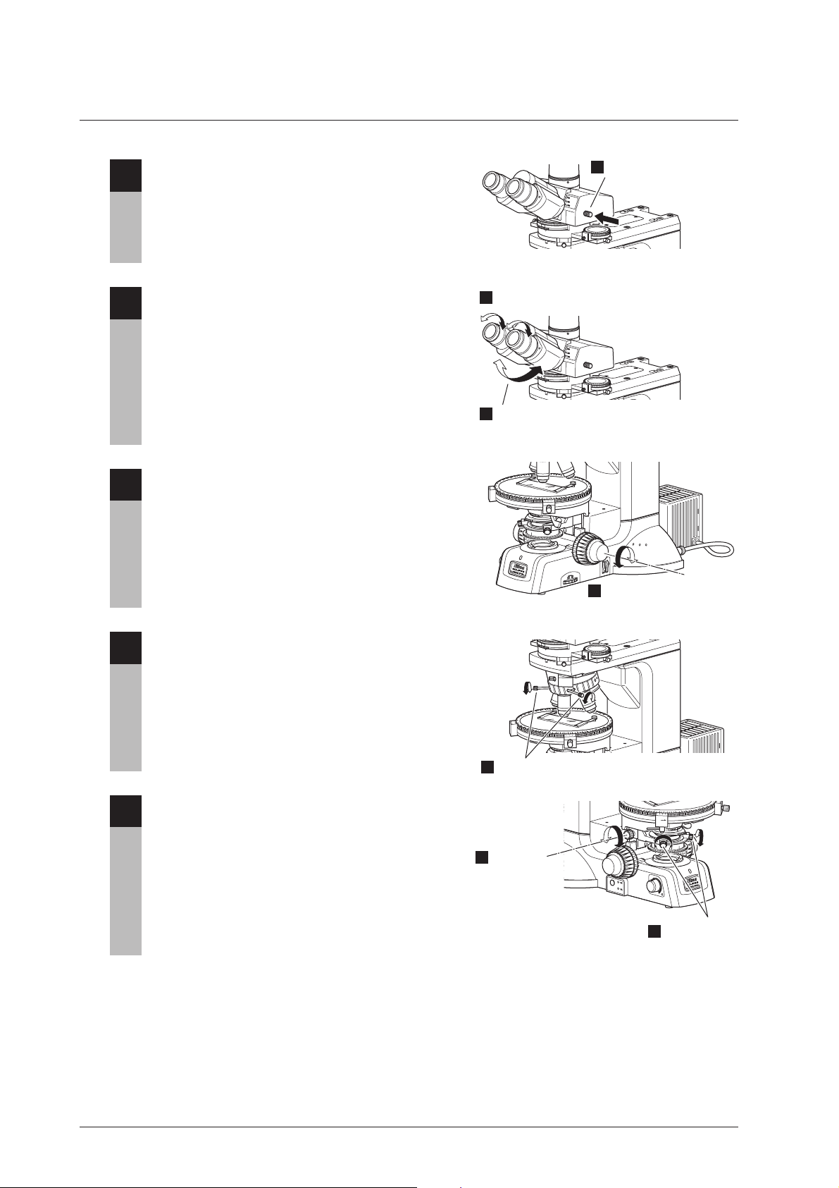
Turn on the power switch of the microscope.
1
When the microscope power is turned on, the
power indicator on the microscope base is lit.
1
Tu r n on
the power.
See Page 22.
E
P
I/D
IA
Push the epi/dia selection switch to select
2
the episcopic illumination. The indicator
for the episcopic illumination (upper side)
turns on.
See Page 23.
ON
CL
I
CK
N
PA
A
J
0
9
0.
2
0.
chr
A
4
.
0
0.6
8
0.
Powe r
indicator
O
F
F
ON
CL
I
CK
N
APA
J
0
9
.
0
2
.
0
chr
A
4
.
0
0.6
8
0.
Turn the brightness control knob to adjust
3
the brightness.
When the brightness control knob is turned, the
brightness of the illumination selected by the epi/
dia selection switch is changed.
See Page 23.
When the lamp lights, the power indicator on the
microscope base lights green.
When necessary, operate the filter slider
4
on the epi illuminator to locate the desired
filters into the optical path.
Filter type
NCB11
(color balancing filter)
ND4, 16
(ND filter)
GIF
(
green interference filter
IF
(interference filter)
)
Intended use
For color balance adjustment
and color photomicrography
For brightness adjustment
(ND4: transmittance 25%,
ND16: transmittance 6%)
For contrast adjustment
For interference
Select the episcopic
2
illumination. The upper
indicator lights.
BINO
BINO
&
PHOTO
PHOTO
0
BF
F
D
EP
I/D
IA
O
FF
Adjust the
3
brightness.
Set the appropriate
4
filter into the
optical path.
STOP
.
A
STOP
.
F
18
 Loading...