

Nikon Eclipse LV100DA-U Instructions Manual

M421 E 07.5.NF.1 (2/3)
Universal Design Microscope UDM
ECLIPSE LV100DA-U
Instructions

Thank you for purchasing the Nikon product.
This instruction manual is written for the users of the Nikon Universal Design
Microscope UDM ECLIPSE LV100DA-U.
To ensure correct usage, read this manual carefully before operating the product.
• It is prohibited to reproduce or transmit this manual in part or whole without Nikon’s
expressed permission.
• The contents of this manual are subject to change without notice.
• Although every effort has been made to ensure the accuracy of this manual, if you
note any points that are unclear or incorrect, contact your nearest Nikon
representative.
• Some of the products described in this manual may not be included in the set you
have purchased.
• Also be sure to read the manuals for any other products that you are using with this
system.
• If the equipment is used in a manner not specified by the manufacturer, the protection
provided by the equipment may be impaired.
WARNING and CAUTION Symbols Used in This Manual
Although this product is designed to be completely safe during use, incorrect usage or
failure to follow the safety instructions provided may cause personal injury or property
damage. To ensure correct usage, read this manual carefully before using the product.
Do not discard this manual and keep it handy for easy reference.
Safety instructions in this manual are marked with the following symbols to highlight
their importance. For your safety, always follow the instructions marked with these
symbols.
Symbol Meaning
WARNING
CAUTION
Disregarding instructions marked with this symbol may lead
to serious injury or death.
Disregarding instructions marked with this symbol may lead
to injury or property damage.
Meaning of Symbols Used on the Product
Symbol Meaning
Caution for heat
This marking on the back of the lamp house and near the
lamp house clamp screw of the “LV-UEPI 2A Motorized
Universal Epi Illuminator 2A” calls your attention on the
following:
You can see the positions of this symbol on Page 8 and 12.
• The lamp house becomes extremely hot while the lamp is
on and immediately after it is turned off.
• Do not touch the lamp house during and immediately after
lighting to prevent the risk of burns.
• Make sure that the lamp house is sufficiently cool before
the lamp replacement.
1

WARNING
1. Intended product use
The product should only be used for microscopic observation. Do not use this microscope
for other purpose. In addition, do not try to put a large specimen on the stage if the specimen
is larger than the stage.
2. Do not disassemble
Disassembling the microscope or the microscope system may result in electric shock or
malfunctions. Damage or injury that may occur due to mishandling is unwarranted. Never
attempt to disassemble any part other than the parts described in this manual. If you
experience problems with the microscope or the microscope system, contact your nearest
Nikon representative.
3. Read the instructions carefully
To ensure safety, carefully read this manual and the manuals for other equipment used with
this microscope. In particular, observe all warnings and cautions given at the beginning of
each manual.
To use an external light source
When an external light source, such as a mercury lamp or a xenon lamp, is used, you must
take great care of the lamp. Read the instruction manual for the light source and follow the
instructions and cautions for it.
4. Ratings of the power supply
The power supply circuit in this product is designed for AC power of 100 to 240 VAC and
50/60 Hz. Before connecting the power cord, check that the power supply to be used
conforms to the voltage and frequency described above. Use of a non-conforming power
line may result in equipment malfunction, failure, or fire.
5. Power cord
Be sure to use the specified power cord for the product. Using a wrong power cord may
result in malfunctions or fire. The product is classified as subject to Class I protection
against electrical shock. Make sure it is connected to an appropriate ground terminal
(protective earth terminal). To prevent electrical shock, always turn off the power switch
(press it to the “ ” position) for the microscope before attaching or detaching the power
cord. For specifications of the power cord, refer to “VII. Specifications.”
6. Specified light source
Use this product with a specified light source. The specified light source devices are as
follows:
• Illuminator (for the epi-illumination):
Nikon LV-UEPI2A Motorized Universal Epi Illuminator 2A (model name: LV-UEPI2A)
• Lamp house (for the epi-illumination and the dia-illumination)
Nikon LV-LH50PC Precentered Lamp House 12V 50W (model name: LV-LH50PC)
• Lamp
Nikon LV-HL50W 12V 50W LONGLIFE halogen lamp (model name: LV-HL50W), or
non-Nikon 12V 50W SHORTLIFE halogen lamp (model name: OSRAM HLX 64610,
OSRAM HLX 64611, or PHILIPS 7027).
• Power supply (It is used to turn on the episcopic illumination and the diascopic
illumination simultaneously.)
Nikon TE2-PS100W Power Supply (model name: TE2-PS100W)
This power supply is connected to the lamp house for the episcopic illumination to turn on
the episcopic illumination and the diascopic illumination simultaneously.
If you wish to buy these lamps, please contact your nearest Nikon representative.
2

WARNING
7. To use an external light source
To perform an epi-fl microscopy with the LV-UEPI2A epi illuminator, the brightness of the
specified light source may be less than the desired brightness. In this case, the light source
described below can be used for the LV-UEPI2A epi illuminator.
• Light source
Nikon Inensilight C-HGFIE HG Precentered Illuminator (model name: C-HGFIE, electric operation
type) or X-Cite 120 PC (electric operation type) made by EXFO Electro Optical Engineering Inc.
If a manual operation type light source is attached, you cannot control the shutter and the
brightness on the microscope. Make sure to use the light source specified above.
Note that if the light source described above is used with the product, the product is not
approved as a UL listed product.
8. Heat from the light source
The lamp and the lamp house become extremely hot. To avoid burns, do not touch the lamp
house while the lamp is lit or for thirty minutes after it is turned off. Furthermore, to avoid
the risk of fire, do not place fabric, paper, or highly flammable volatile materials (such as
gasoline, petroleum benzine, paint thinner, or alcohol) near the lamp house while the lamp is
lit or for about thirty minutes after it is turned off.
9. Air vents
Do not block the air vents on the microscope and the lamp house. If the air vents are
blocked, the temperature of the microscope will rise. And it results in damage or fire.
10. Ultraviolet light from an external light source
If you use an external light source other than the specified ones and that has a mercury lamp, a
xenon lamp, or so on, the light source radiates ultraviolet light, which is harmful to the eyes and
skin, from the emission port. Direct viewing of light from these lamps may result in snow blindness
at a light case or blindness at the worst case. To prevent injury, follow the guidelines below:
1) Place a UVC collector lens into the optical path of the microscope unless the
UV excitation light is necessary.
On the LV-UEPI2A epi illuminator, an UV filter automatically enters the optical path when
the microscopy method is turned to the bright-field microscopy or the dark-field
microscopy. The UV filter is removed from the optical path when the microscopy method
is turned to the epi-fl microscopy 1 method (FL1) or the epi-fl microscopy 2 method (FL2).
2) When performing the epi-fl microscopy by using the UV excitation light, attach
the filter cube dedicated to the UV excitation light. If you must see the objective
or its surroundings, be sure to see through the ultraviolet light shield.
3) Use the light source with the microscope.
The light source device is required to be connected to the microscope whenever the light source
device is energized. Do not turn on the light source if it is not connected to the microscope, and
do not disconnect the light source from the microscope while the light source is lit.
When disconnecting the light source from the microscope, turn off the power to the light
source, and then unplug the power cord from the wall outlet.
11. Reflection
Lustrous specimens reflect the illumination. Do not observe the illuminated surface of a
specimen for a long time because the strong reflection may hurt your eyes. Make sure to see
the specimen through the ultraviolet light shield.
12. Cautions on operating the motorized units
The product can be controlled on a PC with “NIS-Elements,” the software for digital
cameras, when a digital camera is used with the product. To avoid unexpected injuries, note
the following when operating this product with a PC.
Before operating the product, check all moving parts for your safety.
• If you touch the nosepiece, objectives, or parts on the stage during operation, it may cause
injury to hands or fingers. Do not touch these devices or parts when operating.
3

CAUTION
1. Handle with care
2. Do not wet the microscope
3. Weak electromagnetic waves
4. Installation location
This product is a precision optical instrument. Handle the microscope system with care to
avoid shock on impact.
In particular, objectives may loose accuracy when exposed to even a weak physical shock.
If the microscope gets wet, a short circuit may cause malfunction or abnormal heating of the
microscope. If you accidentally spill water on the microscope, immediately turn off the
power switch (flip it to the “ ” side) and unplug the power cord from the wall outlet. Then,
wipe off the water with a piece of dry cloth. If water enters a component, immediately
suspend use of this product, disconnect the power cord from the outlet, and contact your
nearest Nikon representative.
The product emits weak electromagnetic waves. The accuracy of any precision electronic
equipment may be adversely affected if positioned too close. To prevent bad influences,
locate such electronic equipment away from the microscope system. If a TV or radio
reception is affected, move the TV or radio set farther from the product.
The product is a precision optical instrument. So, the usage or storage in an inappropriate
environment may result in malfunctions or poor performance.
Consider the following factors when selecting an installation location:
• Avoid a brightly lit location, such as exposed to direct sunlight or directly under a room
light. If there is excessive ambient light, the image quality deteriorates.
• Always install the product with a surrounding clear area of 10 cm or more.
• Install the product in a location that is free from considerable dust or dirt.
• Install the product on a flat surface with little vibration.
• Install the product on a sturdy desk or table for the base of the microscope system.
• Do not install the product in a hot and humid location.
• Select a layout that allows easy removal of the power cord from the product's AC inlet in
the event of an emergency.
• For details about the operating environment and storage environment, see “VII.
Specifications.”
5. Cautions on moving the microscope
• This product is a precision optical instrument. Handle it carefully and do not subject it to a
strong physical shock. (In particular, objectives may loose accuracy when exposed to even
a weak physical shock.)
• When moving the microscope, first remove the stage and the lamp house. Then, securely
hold the microscope by the root of the arm from the back.
(Information) The microscope with the stage, eyepiece tube, lamp house, and other parts
attached, weighs approximately. 20 kg.
• Do not hold the focus knobs, eyepiece tube, lamp house, sub-stage, or so on, when
carrying the microscope. They may come off and may cause serious injury or malfunction.
• Before carrying the stage, attach fixing metals for transportation to fix the stage plate.
• Be careful not to pinch your hands or fingers during transportation.
6. Cautions on assembling the microscope
• Be careful not to pinch your fingers or hands during assembly.
• Scratches or fingerprints on the lenses will adversely affect the image. Be careful not to
scratch or touch the lens surfaces.
4

CAUTION
7. Cable routing
8. Cautions when replacing lamps
9. Notes on handling a filter cube
Make sure the cables are routed properly. Do not bring the cables into contact with the lamp
house for the diascopic illumination. If a cable comes into contact with the lamp house, the
cable sheath may melt and it results in an electrical shock or fire.
• To prevent burn injuries, wait at least 30 minutes after the lamp is turned off to give it
sufficient time to cool down when replacing lamps.
• To prevent electrical shock and damage to the microscope, always turn off the power
switch (flip it to the “ ” side) and unplug the power cord from the outlet before attaching
or detaching the lamp house.
• Never touch the glass surface of the lamp with bare hands. Doing so will cause
fingerprints, grease, etc. to burn onto the lamp surface, reducing the illumination. If you
do get any fingerprints or dirt on the lamp, wipe them clean.
• Make sure the lamp house cover is securely fitted to the lamp house after replacing lamps.
Never turn on the lamp with the lamp house cover removed.
• When you dispose of the replaced lamp, do not break it up. Instead, dispose of the used
lamp as special industrial waste or dispose of it according to the local regulations and
rules.
When using the product configured with the illuminator LV-UEPI2A, a filter cube can be
attached to enable epi-fl microscopy. Note the following precautions for handling a filter
cube.
• Interference filters (especially excitation light filters, which are exposed to strong light)
deteriorate over time. Replace them depending on their total operating hours.
• Filter characteristics may alter if the filter is exposed to high humidity. To prevent
changes or degradation of filter characteristics, avoid using or storing the filters under
conditions of high humidity or high temperature and avoid subjecting the filters to rapid
temperature changes. When a filter is not in use, store it in a desiccator or hermetically
sealed container with a drying agent.
• The filters attached in the nine types of filter cubes listed below have sharper wavelength
characteristics than standard filters. However, due to their sophisticated coatings, they
must be handled with special care. In particular, take care to avoid abrasion from cleaning.
Observe the procedures described in “1. Cleaning Lenses and Filters” of “VI. Care and
Maintenance.”
Single band filter cubes: DAPI, FITC, TxRed, GFP
Multi band filter cubes: F-R, F-T, D-F, D-F-R, D-F-T
10. Software setup works after assembly
When the microscope is assembled or the configuration of the microscope is changed,
perform the software setup works for various settings of the microscope via a PC by using
the software, “LVSetup,” in “LV Series Support Tools” provided with this product.
In the setup works, information for the parts and devices (objectives, filter cubes,
illuminator, and so on) is registered into the memory in the microscope and interlock
controls for such devices are specified. Make sure to perform the setup works to use the
microscope correctly.
For details about the operation and the setup works of the “LVSetup,” refer to the “LV
Series Support Tools software manual.”
5

CONTENTS
WARNING and CAUTION Symbols Used in This Manual................................. 1
Meaning of Symbols Used on the Product ....................................................... 1
WARNING ........................................................................................................ 2
CAUTION.......................................................................................................... 4
Part Name ..................................................................................................... 8
1 Configuration of the Product and Control Names .............................................................. 8
2To Perform Epi/Dia Simultaneous Illumination ............................................................... 10
3To Use an External Light Source ...................................................................................... 10
4 Operation Panel ................................................................................................................11
5 Connector panel ................................................................................................................11
6 Rear View ......................................................................................................................... 12
Microscopy Method ................................................................................... 13
1 Bright-field Microscopy under the Epi Illumination ........................................................ 15
2 Dark-field Microscopy under the Epi Illumination .......................................................... 17
3 Polarization Microscopy under the Epi Illumination (Simplified/Sensitive Color) ......... 18
4 Differential Interference Contrast Microscopy under the Epi Illumination
(Senarmont Method) ......................................................................................................... 20
5 Differential Interference Contrast Microscopy under the Epi Illumination
(Prism Slide Method) ....................................................................................................... 22
6 Epi-fl Microscopy ............................................................................................................. 24
7 Bright-field Microscopy under the Dia Illumination........................................................ 26
8 Polarization Microscopy under the Dia Illumination (Simplified/Sensitive Color) ......... 28
9 Dark-field Microscopy under the Dia Illumination .......................................................... 29
10 Phase Contrast Microscopy under the Dia Illumination................................................... 30
11 Differential Interference Contrast Microscopy under the Dia Illumination ..................... 32
Operation of Each Part.............................................................................. 34
1Power On/Off ...................................................................................................................34
2 Setting Up the Microscope ............................................................................................... 36
3 Selecting the Microscopy Method .................................................................................... 37
4 Illumination ...................................................................................................................... 41
5 Objective........................................................................................................................... 43
6 Filter ................................................................................................................................. 44
7 Stage ................................................................................................................................. 45
8 Coarse Focus Knob and Fine Focus Knob ....................................................................... 46
9 Eyepiece Tube ..................................................................................................................48
10 Diopter Adjustment .......................................................................................................... 49
11 Interpupillary Distance Adjustment.................................................................................. 49
12
Adjustment for the Episcopic Illumination (Field Diaphragm and Aperture Diaphragm) ...
13 Adjustment for the Diascopic Illumination (Focusing and Centering the Condenser
and Adjusting the Field Diaphragm and Aperture Diaphragm) ....................................... 53
14 Polarizer Slider (for the Episcopic Illumination) ............................................................. 56
15 Polarizer for the Diascopic Illumination .......................................................................... 58
50
6

CONTENTS
16 Analyzer Slider ................................................................................................................. 60
17 PA Block ........................................................................................................................... 61
18 Lambda Plate Slider for the Episcopic Illumination ........................................................ 62
19 Lambda Plate Slider for the Diascopic Illumination ........................................................ 63
20 DIC Prism (For the Episcopic Illumination/Senarmont Method) .................................... 64
21 DIC Prism (For the Episcopic Illumination/Prism Slide Method) ................................... 65
22 DIC Prism for the Diascopic Illumination ....................................................................... 66
23 Filter Cube for Fluorescence Observation ........................................................................ 68
24 Excitation Light Balancer ................................................................................................. 71
Assembly.................................................................................................... 73
1 Assembling the Stage Unit ............................................................................................... 76
2Attaching the Condenser .................................................................................................. 78
3 Attaching the Nosepiece ................................................................................................... 79
4 Attaching the Epi Illuminator ........................................................................................... 82
5 Attaching the Lamp House and Replacing Lamps ........................................................... 85
6 Attaching the Optical Fiber Adapter and an External Light Source................................. 89
7 Attaching the Double Light Source Adapter .................................................................... 92
8 Attaching the Eyepiece Tube............................................................................................ 93
9 Attaching Eyepieces ......................................................................................................... 93
10 Attaching Objectives ........................................................................................................ 93
11 Attaching the Polarizer for the Diascopic Illumination .................................................... 94
12 Attaching Eye Level Risers .............................................................................................. 95
13 Attaching a Column Riser ................................................................................................ 95
14 Connecting a PC ...............................................................................................................96
15 Connecting the DS-L2 ...................................................................................................... 97
16 Connecting the Power Cord.............................................................................................. 98
17 Installing Options ............................................................................................................. 98
18 Anti-static Treatment ........................................................................................................ 98
Troubleshooting......................................................................................... 99
1Viewing Problems and Control Problems ........................................................................ 99
2 Electrical Problems ......................................................................................................... 103
Care and Maintenance ............................................................................ 106
1 Cleaning Lenses and Filters ........................................................................................... 107
2 Cleaning the Painted Parts, Plastic Parts, and Printed Parts ........................................... 107
3 Storage ............................................................................................................................ 107
4Regular Inspections ........................................................................................................ 107
Specifications .......................................................................................... 108
7
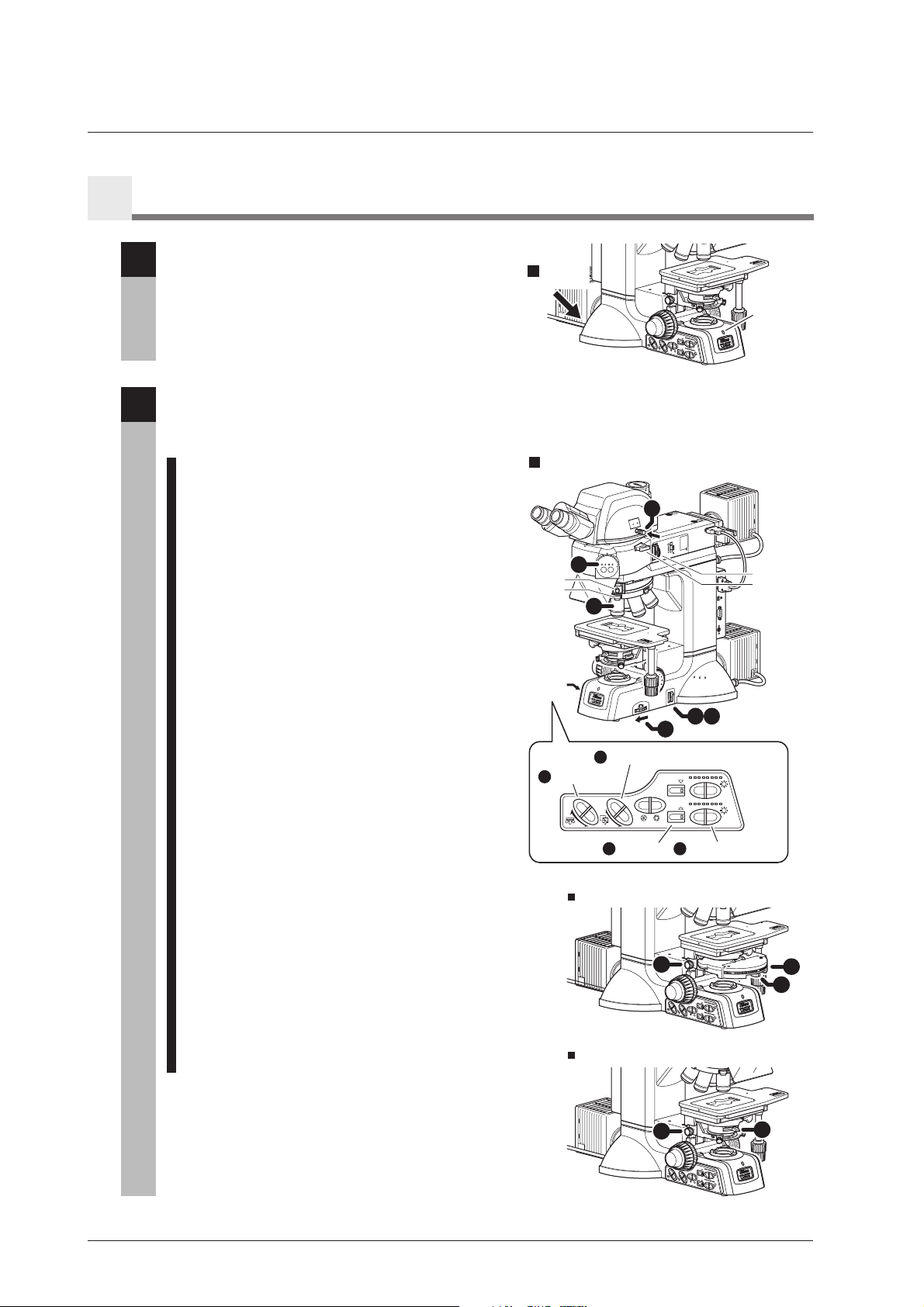
Part Name
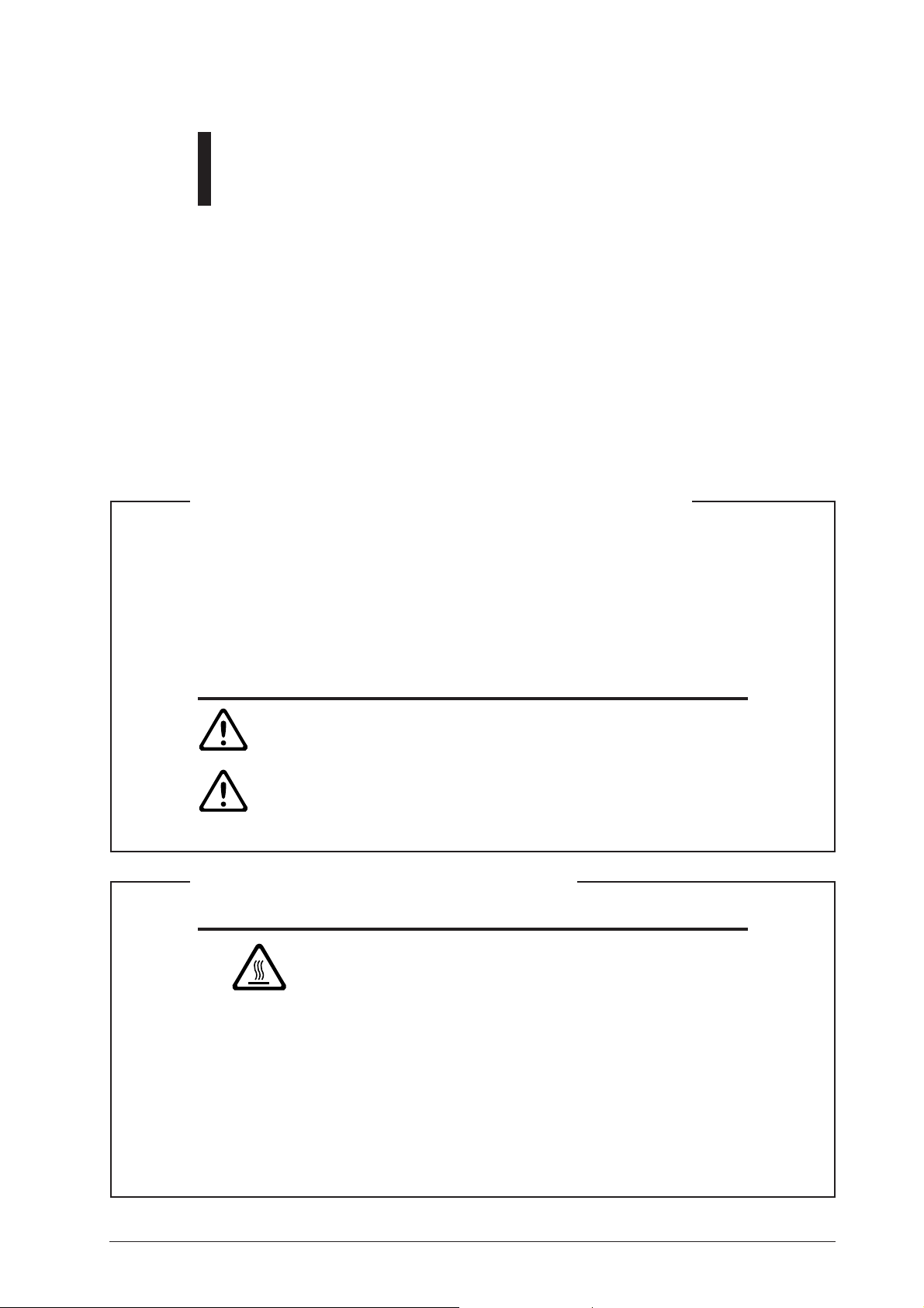
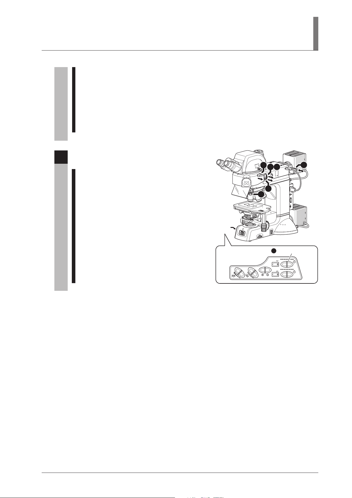
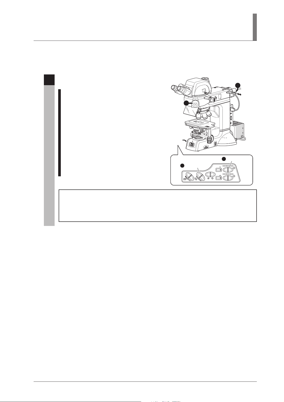
1
Configuration of the Product and Control Names
Front left side of the microscope
This drawing depicts the ECLIPSE LV100DA-U microscope configured with the LV-UEPI2A epi
illuminator, the LV-TT2 eyepiece tube, the LV-NU5AI motorized nosepiece, the 3x2 stage, the glass
slide holder, the diascopic illumination condenser (the slide condenser), the lamp house for the
episcopic illumination, the lamp house for the diascopic illumination, and attachments for the DIC
microscopy.
Lamp house
for the episcopic
illumination
LV-LH50PC
*1
Filter sliders
“CAUTION for heat”
symbol
Excitation light
balancer slot
Aperture diaphragm
centering screw
(on both sides)
Field diaphragm
centering screw
(on both sides)
Filter cube port
Lamp house
for the diascopic
illumination
LV-LH50PC
Power cord
Condenser focus knob
Fine focus knob
Coarse focus knob
Coarse torque adjustment ring
Vertical tube section
OBJ.
Trinocular eyepiece tube
LV-TT2
Binocular section
N
A
P
A
J
Motorized nosepiece
LV-NU5AI
Ultraviolet light shield
GE
A
T
S
PAN
2
A
J
x
3
Objective
Stage
9
.
0
=
2
.
A
.
0
N
.3
chr
0
A
.4
0
.5
0
6
.
0
0.7
0.8
Diascopic illumination
condenser
Stage fine movement
knob for the Y-axis
Stage fine movement
EPI
E
PI
D
I
A
CUBE
A
.
S
.
D
I
A
knob for the X-axis
Power indicator
Operation panel
(See Page 11.)
8
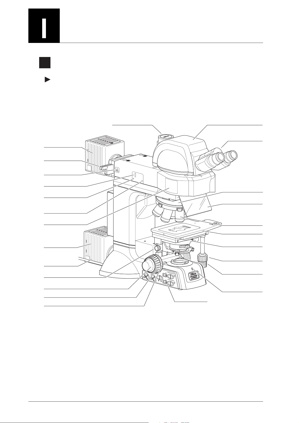
Front right side of the microscope
I. Part Name
Eyepiece
Diopter
adjustment ring
Microscopy method
indicator
Lambda plate
*5
Objective DIC prism slider
Glass slide holder
Condenser scale
Condenser aperture
diaphragm ring
Condenser
centering screw
Clamp screw for
various adapters
UT
O
IN
00
1
0
0
00 2
1
-TT2
LV
J
APA
N
STOP
.
F
Optical path selector lever
Analyzer slider
Polarizer slider
Dummy slider
Connection
cable for the
LV-UEPI2A
*2
*3
*4
Aperture diaphragm
BF DF FL1 FL2
FL1
FL2
UEPI2A
centering screw
(on both sides)
Field diaphragm
open/close lever
*6
3
x
2
S
J
APA
TA
N
0
.
8
0
A
chr
.
7
N
.
A
0
=
0
.6
.
9
JAPAN
0
.
5
0
.
4
0
.3
0.2
0.1
GE
USB
232C
S
R
Field diaphragm
centering screw
(on both sides)
NT
C
L
Connector panel
(See Page 11.)
Coarse focus
stopper ring
Fine focus knob
Field lens
*3
Main body of the microscope
N
.
S
.
F
Field diaphragm control
Filter selector switch
(ND8, NCB)
Tool holder
B
C
N
D8
(For the diascopic illumination)
*1: To turn on the episcopic illumination and the diascopic illumination simultaneously, connect the lamp cable of the lamp house for
the episcopic illumination to an external power supply. (See Page 10.)
If the brightness of the halogen lamp is less than the desired brightness for the epi-fl microscopy or so on, attach an external light
source equipped with a mercury lamp with the fiber adapter and the light guide fiber. (See Page 10.)
*2: This part is used for the DIC microscopy or the polarization microscopy under the episcopic illumination or the diascopic
illumination.
*3: To perform the DIC microscopy or the polarization microscopy under the episcopic illumination, attach the polarizer slider to the
slot on the epi illuminator. To perform the DIC microscopy or the polarization microscopy under the diascopic illumination,
attach the polarizer for the diascopic illumination to the field lens part.
*4: To perform the sensitive color DIC microscopy or the sensitive color polarization microscopy under the episcopic illumination,
insert the lambda plate slider.
*5: This is used to perform the sensitive color DIC microscopy or the sensitive color polarization microscopy under the diascopic
illumination.
*6: This is used to perform the DIC microscopy.
9
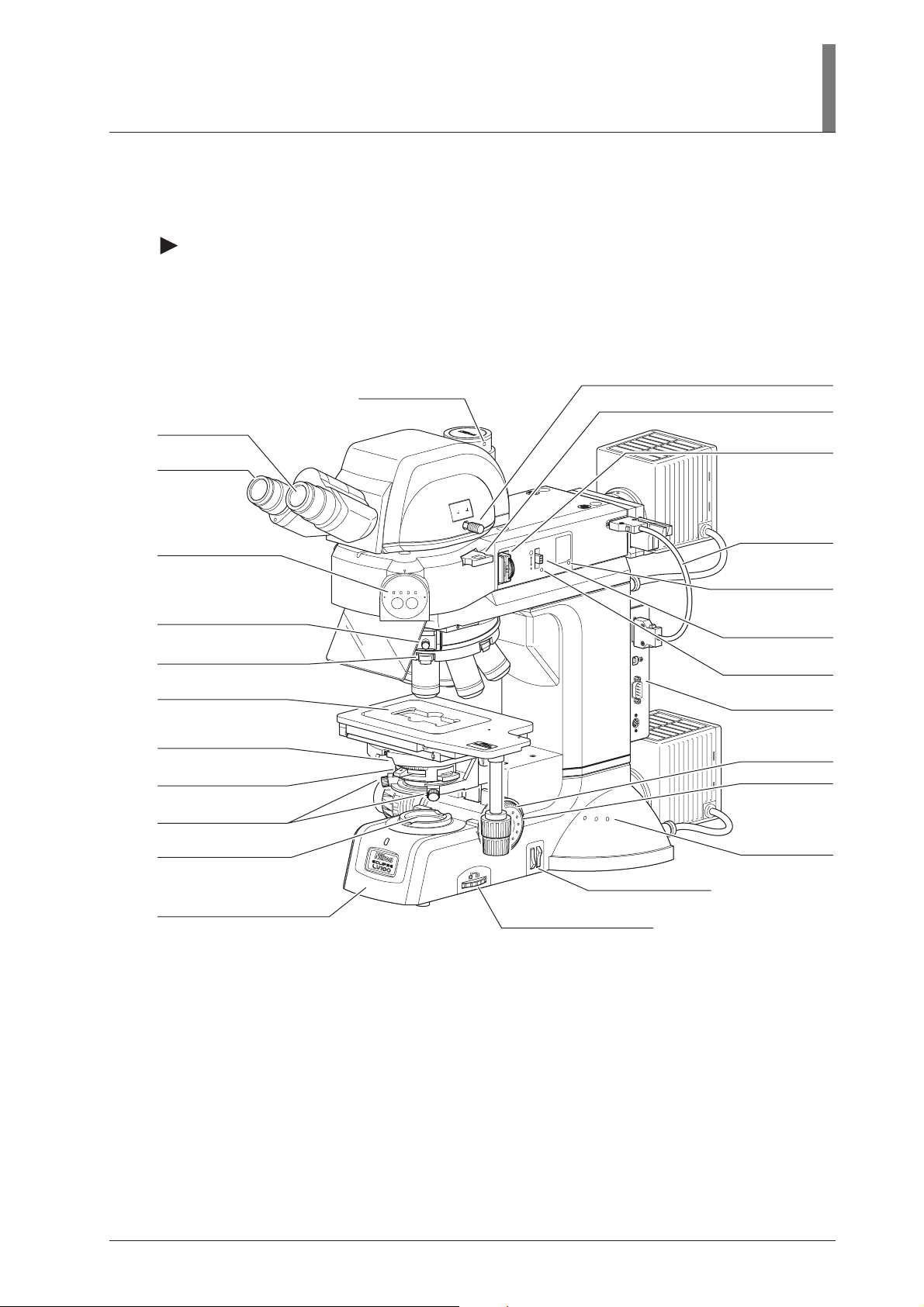
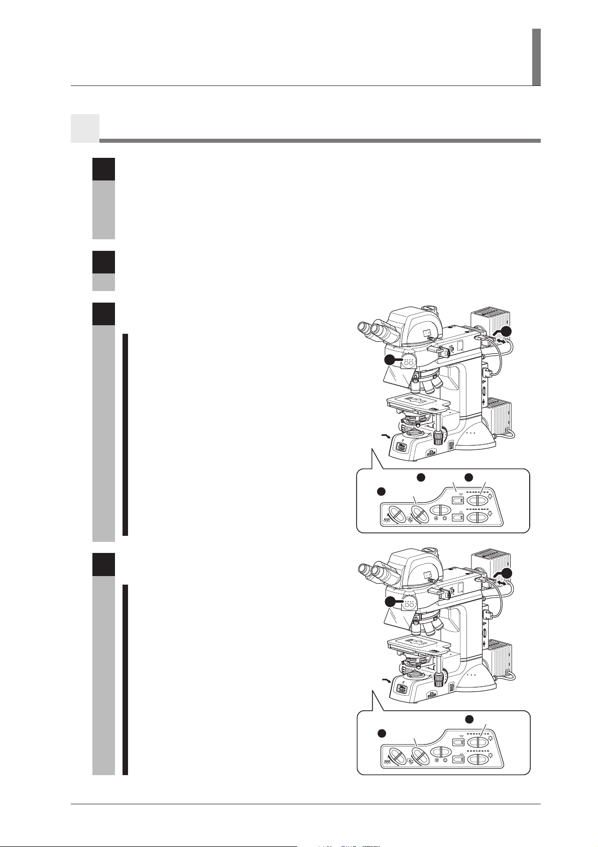
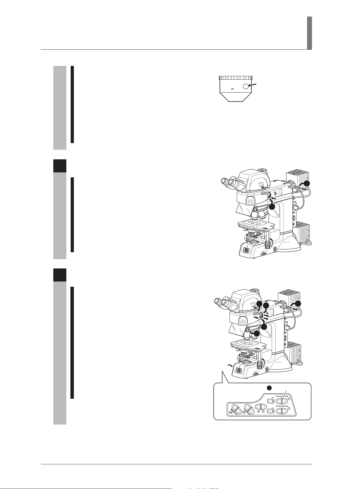
2
To Perform Epi/Dia Simultaneous Illumination
The drawing below depicts the LV100DA-U microscope configuration to use the episcopic illumination
and the diascopic illumination simultaneously. To turn on the both illumination simultaneously, the
lamp house for the episcopic illumination must be connected to an external power supply (TE2PS100W).
OUT
IN
100
0
0
2
0
10
2
T
T
-
LV
J
A
P
A
N
STOP
.
F
BF DF FL1FL2
FL2
FL1
3
x
2 S
J
A
T
P
A
A
N
G
0
.8
0
A
ch
.
7
0
.
6
0
.
5
E
r
N
.
A =
0
.
9
JAPAN
0
.
4
0
.
3
0.2
0.1
NCB
8
ND
.
S
F.
A
I2
P
E
U
B
US
32C
2
RS
T
CN
L
Lamp cable
Control cable
PO
W
ER
M
IN
.
MA
X
.
Power cord
Power supply (TE2-PS100W)
3
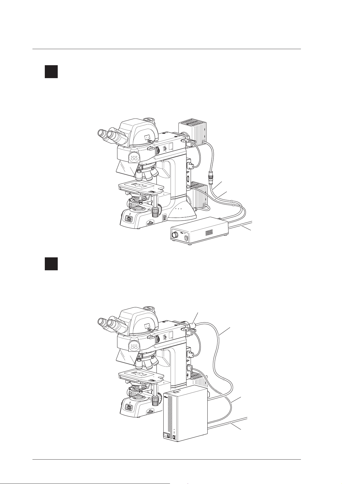
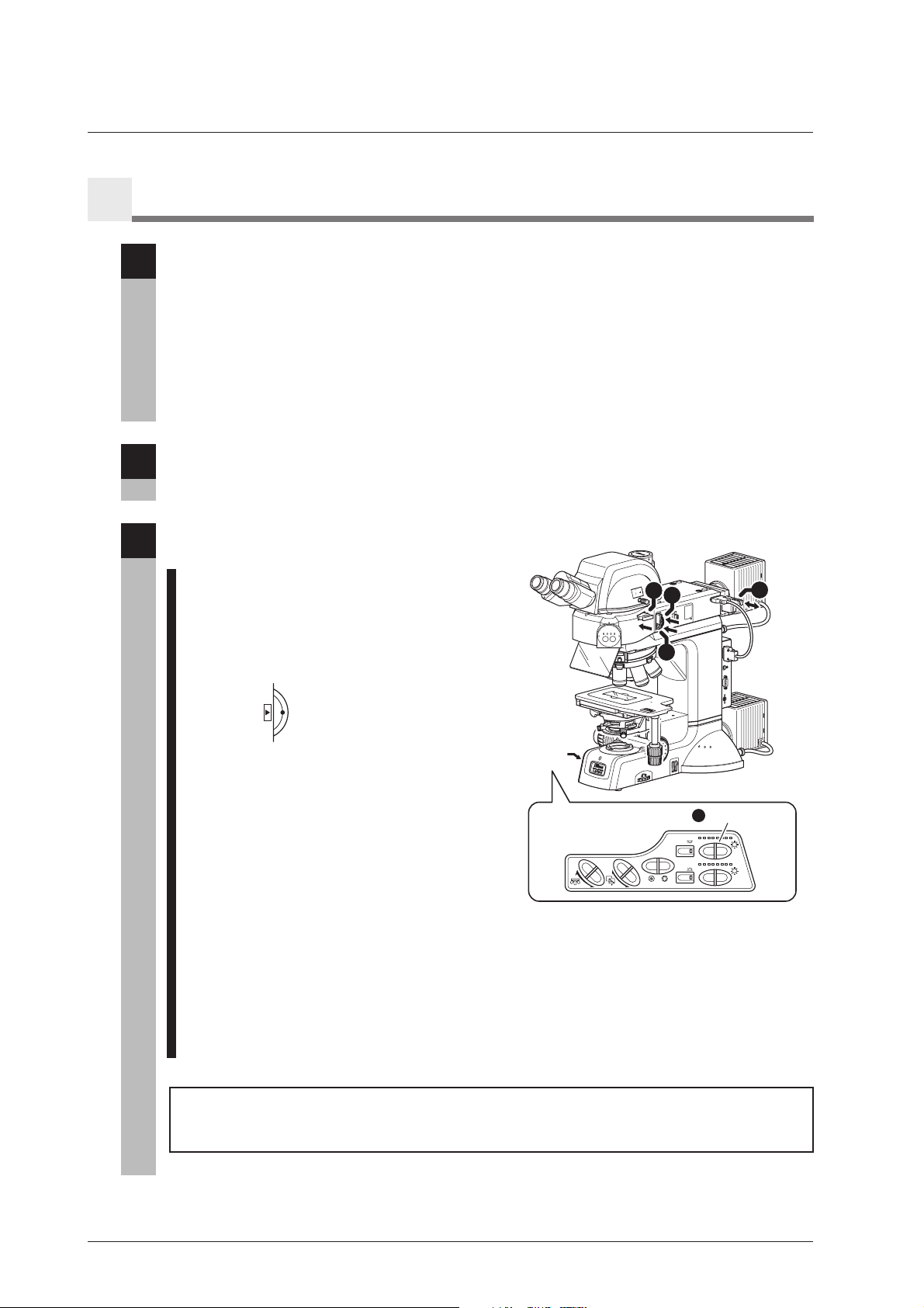
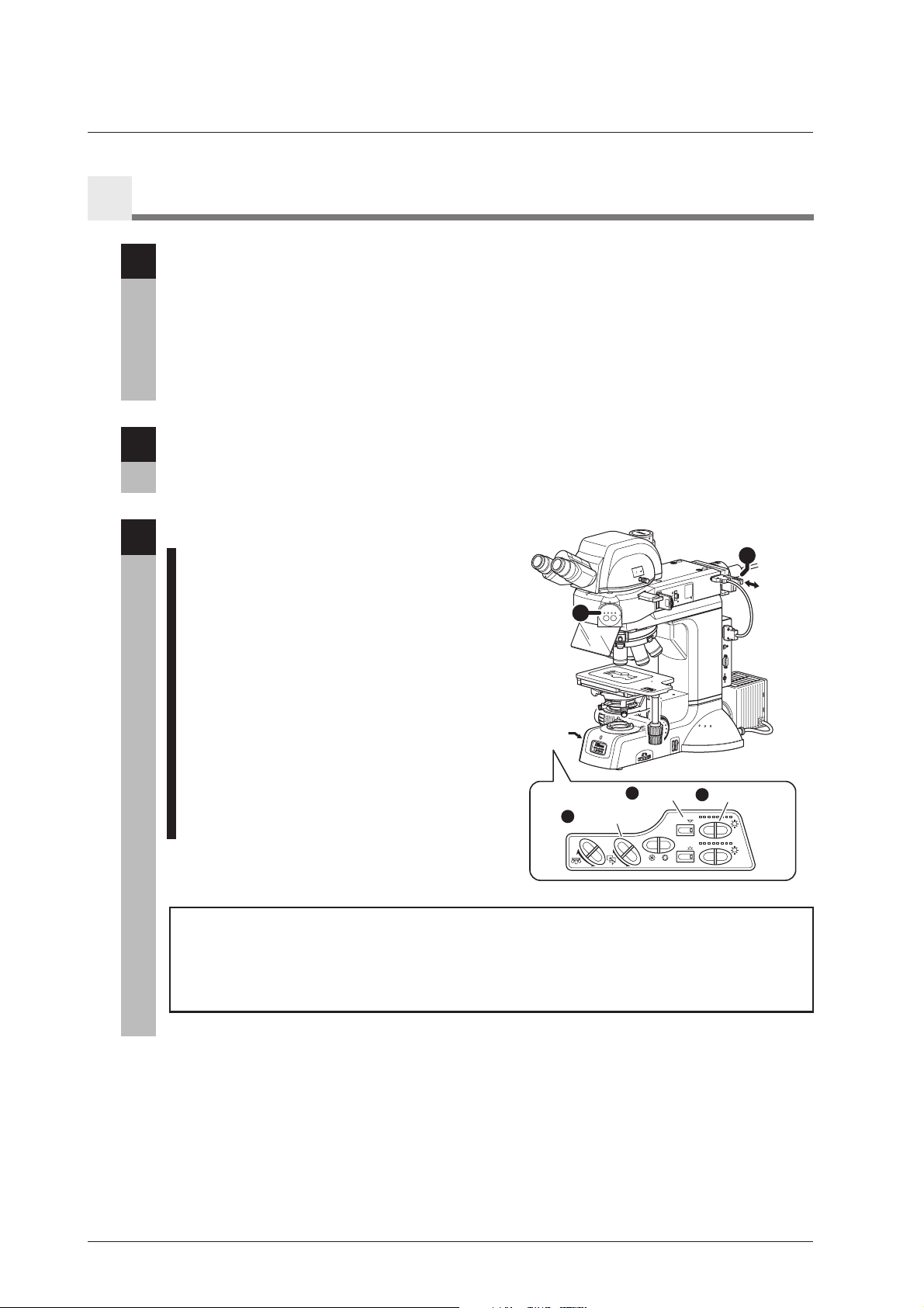
To Use an External Light Source
The drawing below depicts the LV100DA-U microscope with the LV-UEPI2A epi illuminator, the LVHGFA optical fiber adapter, the light guide fiber, and the external light source (Intensilight C-HGFIE).
To perform the epi-fl microscopy, this configuration is used.
Optical fiber adapter
PAN
JA
I2A
P
E
U
B
US
32C
2
RS
CNT
L
Light guide fiber
RS-232C cable
BF DF FL1FL2
FL1
0
.8
0
.
7
OUT
IN
100
0
20
100
2
T
T
-
LV
J
A
P
A
N
STOP
.
F
FL2
3
x
2 S
J
A
T
P
A
A
N
G
A
chr
0
.
6
0
.
5
E
N
.
A =
0
.
9
JAPAN
0
.
4
0
.
3
0.2
0.1
I
NT
E
NS
IL
I
G
HT
C
H
G
F
IE
NCB
8
ND
.
S
F.
10
External light source
(Intensilight C-HGFIE)
L
A
M
P
R
UN
T
I
M
E
hrs
.
P
O
W
E
R
Power cord
4
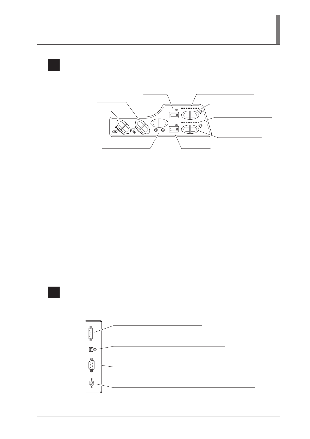
Operation Panel
On the operation panel, there are switches to operate electric operation parts in the microscope.
I. Part Name
EPI brightness level indicator
EPI brightness switch
EPI
DIA brightness level indicator
DIA
DIAswitch
DIA brightness switch
CUBE switch
OBJ.switch
(For the episcopic illumination)
OBJ.
CUBE
A.S. switch
EPI switch
EPI
DIA
A.S.
OBJ. switch:
It is used to rotate the nosepiece and change objectives.
CUBE switch:
It is used to rotate the filter cube turret in the LV-UEPI2A and change microscopy methods.
A.S. switch:
It is used to adjust the opening of the aperture diaphragm in the LV-UEPI2A.
EPI switch / DIA switch:
They are used to turn on/off the lamps for the illumination. When the external light source is used, these
switches are used to open/close the shutter in the light source. When one of the lamps for the
illumination is lit or when the shutter in the light source is opened, the indicator for the corresponding
switch is lit.
EPI / DIA brightness level indicator:
They display the brightnesses of the lamps.
EPI / DIA brightness switch:
They are used to adjust the lamp brightnesses. When a halogen lamp is used for the illumination, its
brightness can be adjusted with continuous settings. When the external light source is used, its
brightness can be adjusted in five steps.
5
Connector panel
On the connector panel, there are connectors for electric operation parts and a PC.
UEPI2A
USB
RS232C
LCNT
UEPI2A connector
It is used to connect the LV-UEPI2A epi illuminator.
USB connector
It is used to connect a PC or the DS-L2 to perform the setup work.
RS232C connector
It is used to connect the external light source (Intensilight C-HGFIE or
EXFO X-Cite 120 PC).
LCNT connector
It is used to connect the external power source for the halogen lamp (TE2-PS100W).
(Only for the simultaneous usage of the episcopic illumination and the
diascopic illumination)
11
I. Part Name
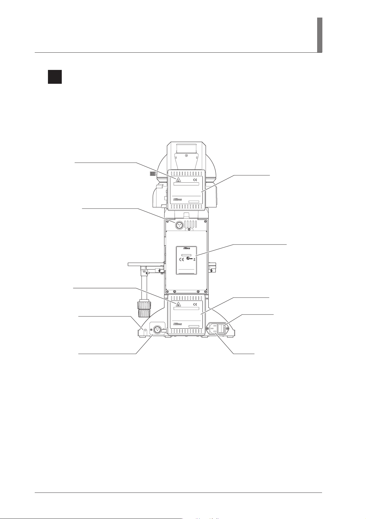
6
Rear View
This drawing depicts the Eclipse LV100DA-U microscope configured with the LV-UEPI2A epi
illuminator, the LV-TT2 eyepiece tube, the 3x2 stage, the lamp house for the episcopic illumination,
and the lamp house for the diascopic illumination
“CAUTION for heat” symbol
CAUTION label
- High Temperature -
CAUTION !
1.
Do not touch the lamphouse while the lamp is lit.
The surface of the lamphouse becomes hot when
the lamp is on.
2.
Turn off the power and allow the lamp and lamphouse to cool enough before replacing the lamp.
Wait for at least 30 minutes after turning off
the lamp
Use 12V50W HALOGEN lamp only.
3.
HALOGEN 12V50W
Lamphouse connector
for episcopic illumination
LAMP
DC12V 50W
LV-LH50PC
JAPAN
652702
“CAUTION for heat” symbol
Tap for grounding (M4)
Lamphouse connector
for diascopic illumination
LAMP
DC12V 50W
ECLIPSE LV100DA-U
100–240V~ 1.2A 50/60Hz
MADE IN JAPAN
921001
4N75
INSPECTION
EQUIPMENT
This device complies with Part 15 of
the FCC Rules. Operation is subject
to the following two conditions:
(1) this device may not cause harmful
interference, and (2) this device must
accept any interference received,
including interference that may cause
undesired operation.
This Class A digital apparatus complies with
Canadian ICES-003.
Cet appareil numérique de la classe A est
confirme à la norme NMB-003 du Canada.
- High Temperature -
CAUTION !
Do not touch the lamphouse while the lamp is lit.
1.
The surface of the lamphouse becomes hot when
the lamp is on.
Turn off the power and allow the lamp and lamp-
2.
house to cool enough before replacing the lamp.
Wait for at least 30 minutes after turning off
the lamp
Use 12V50W HALOGEN lamp only.
3.
HALOGEN 12V50W
LV-LH50PC
JAPAN
652702
Input voltage indication
CAUTION label
Power switch
AC inlet
12

Microscopy Method
CAUTION
This chapter explains the procedure of each microscopy.
• See “IV. Assembly,” when the microscope has not been assembled yet.
• For detailed information about operations of parts of the microscope, refer to “III. Operation of
Each Part.”
Before performing microscopy
• Before using the microscope, please set up the LV100DA-U using “LVSetup” on a
PC contained in “LV Series Support Tools.”
• In this chapter, the microscopy is described with the interlock control of LVSetup
set to the Default mode. When the interlock control mode is set to the Optional
mode, the microscope may behave differently from the ways that are described in
this chapter.
• The interlock control of each electrically-driven device can be enabled using
LVSetup. When this function is enabled, the corresponding electrical devices are set
to the predetermined conditions in accordance with the microscopy method or
objective. If the interlock control is disabled, please be sure to operate each device
manually.
• For operations of LVSetup, see “LV Series Setup Tools Software Manual.”
• Motorized units can be controlled on a PC with “NIS-Elements,” the software for
digital cameras, when a digital camera is used with the product. For details, see the
instruction manual for the “NIS-Elements.”
13

Microscopy methods list
See the table below for the microscopies available with the product, as well as the optional
accessories required for each microscopy.
Microscopy
Bright-field microscopy under
the epi-illumination
Dark-field microscopy under
the epi-illumination
Polarization microscopy under
the episcopic illumination
(simplified/sensitive color)
Differential interference
contrast microscopy under
the epi-illumination
Microscopy
Method
p.15
p.17
p.18
p.20
p.22
Required accessories (optional)
—
BD objective
Polarizer slider and analyzer slider
(The PA block can be used for the simplified
polarization.),
lambda plate slider (for the sensitive color)
Senarmont method
Polarizer slider (equipped with the 1/4 lambda
plate), analyzer slider, and lambda plate slider
(for the sensitive color)
DIC prism slider (suitable for the objective)
LU objective for industrial microscopes
(Objectives marked “LU” are suitable for DIC
microscopy.)
Prism slide method
Motorized universal quintuple nosepiece (LVNU5A or LV-NU5AC), polarizer slider, analyzer
slider, lambda plate slider (for the sensitive color),
DIC prism slider (L-DIC/L-DIHC), and LU
objective for industrial microscopes (Objectives
marked “LU” are suitable for DIC microscopy.)
Epi-fl microscopy
Bright-field microscopy
under the dia-illumination
Polarization microscopy under
the diascopic illumination
(simplified/sensitive color)
Dark-field microscopy under
the dia illumination
Phase contrast microscopy
under the dia illumination
Differential interference
contrast microscopy under
the dia illumination
p.24
p.26
p.28
p.29
p.30
p.32
Filter cube (Up to two cubes can be attached.)
Fluorescence excitation light balancer (optional)
Condenser lens and additional lens
(when the universal condenser is used, for the
2x to 4x objectives)
Condenser lens, polarizer for the diascopic
illumination, analyzer, and lambda plate
(for the sensitive color)
Universal condenser, dark-field annular diaphragm
(or dark-field condenser) diaphragm, and objective
with a numerical aperture of 0.7 or less
Universal condenser, Ph annular diaphragm
(suitable for the objective), and Ph objective
Universal condenser, rotatable polarizer for the
diascopic illumination, analyzer, condenser DIC
prism (suitable for the objective), objective DIC
prism (suitable for the objective), DIC objective
for biologic microscopes, and lambda plate (for
the sensitive color)
14
Bright-field Microscopy under the Epi Illumination
1
II. Microscopy Method
Turn on the power switch.
1
When the power to the microscope is turned on, the
microscope starts initialization. And then, the power
indicator on the microscope base is lit. (See Page 34.)
Set the microscope for the bright-field
2
microscopy under the epi illumination.
If accessories for the DIC microscopy under the
episcopic/diascopic illumination (*1 to *4) are in place,
pull them out of the optical path.
1 Push in the optical path selector lever and select
100% for the binocular eyepiece. (See Page 48.)
2 Press the CUBE switch on the operation panel
and light up the “BF (bright-field)” position of
the microscopy method indicator. (See Page 37.)
The episcopic illumination lamp is turned on with
the predetermined light quantity, and the aperture
diaphragm for the episcopic illumination is
adjusted to the predetermined size automatically
by the interlock control function.
3 Press the OBJ. switch on the operation panel and
locate the 10x objective into the optical path.
(See Page 43.)
4 Locate the NCB11 filter into the optical path and
compensate the color temperature.
(See Page 44.)
5 Adjust the brightness with ND filters.
(See Page 44.)
6 Move the open/close lever to the upper position
to fully open the field diaphragm for the
episcopic illumination. (See Page 50.)
1
Turn on
the power.
O
B
J
.
C
U
B
E
2
Set the microscope for the bright-field microscopy
under the epi illumination.
1
OUT
IN
0
10
0
20
0
0
1
2
T
T
V-
L
J
A
P
A
N
BF DF FL1 FL2
2
FL2
*
1
*
2
FL1
9
.
0
=
2
.
A
.
0
N
r
h
3
.
c
0
A
4
.
0
5
0.
6
.
0
7
0.
0.8
EP
I
EP
I
D
I
A
A
.
S
.
D
I
A
6
STOP
.
F
3
3
x
2
S
J
A
T
P
A
A
N
G
E
0
.
8
0
A
chr
.
7
N
.
A
0.6
=
0
.
9
JAPAN
0
.
5
0
.
4
0
.
3
0.2
0.1
Operation
panel
OBJ. switch
3
OBJ.
CUBE
CUBE switch
2
3
Set the specimen onto the stage and adjust the focus
and the brightness.
B
C
N
8
D
N
.
S
.
F
EPI
DIA
A.S.
N
APA
J
E
AG
T
N
S
PA
2
JA
x
3
Power
indicator
54
UEPI2A
*
3
*
4
SB
U
C
2
3
S2
R
NT
C
L
EPI
DIA
Set the specimen onto the stage and adjust the
3
focus and the brightness.
1 Lower the stage by turning the coarse/fine focus
knobs. (See Page 46.)
2 Set the specimen onto the stage.
3 Turn the coarse/fine focus knobs and focus on
the specimen. (See Page 46.)
4 Turn on the episcopic illumination lamp with the
EPI switch on the operation panel and adjust the
brightness of the lamp with the EPI brightness
switch. (See Pages 41 and 42.)
2
E
G
TA
S
PAN
2
A
J
x
3
9
.
0
=
2
.
A
.
0
N
3
.
chr
0
A
4
.
0
0.5
6
.
0
7
0.
1 3
O
BJ
.
CU
EPI switch
4
OBJ.
CUBE
0.8
EPI
E
PI
D
I
A
A.
B
E
S
.
D
I
A
EPI brightness
4
EPI
DIA
A.S.
switch
EPI
DIA
15
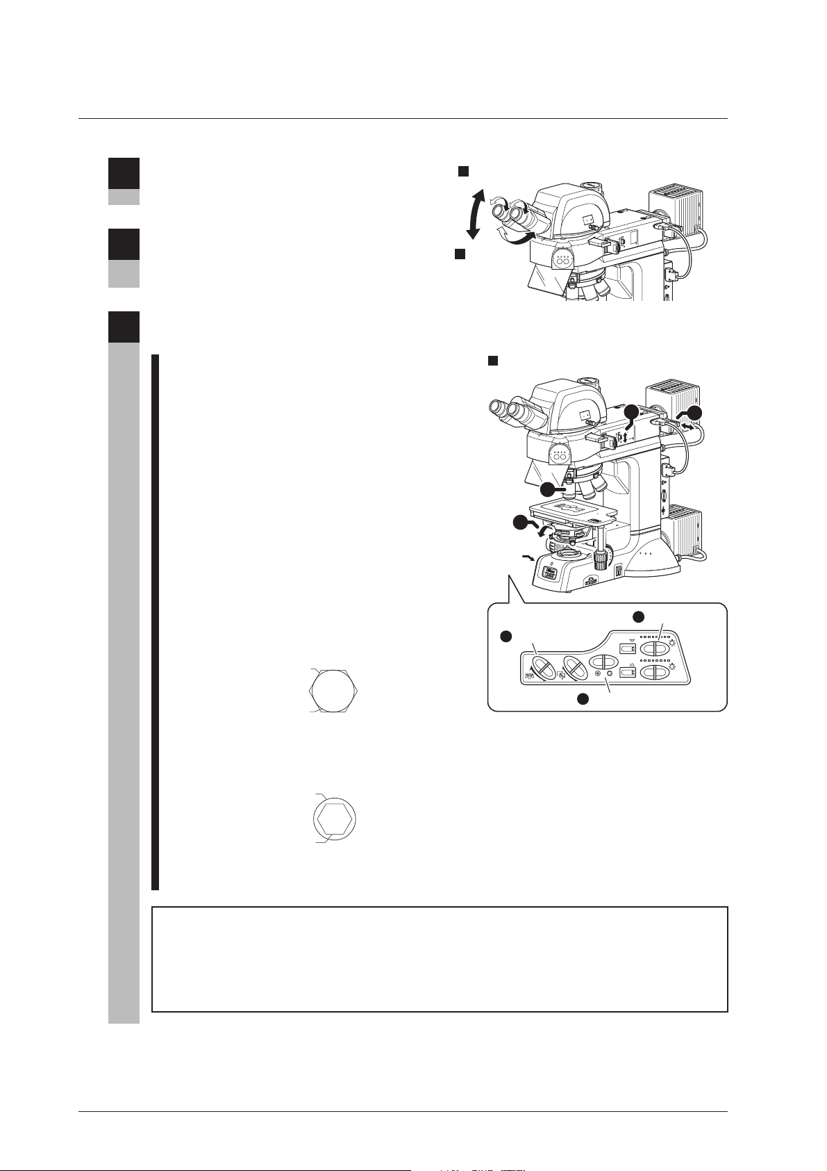
Adjust the angle of the binocular eyepiece.
4
(for the LV-TT2)
(See Page 48.)
Adjust the diopter and the interpupillary
5
distance.
(See Page 49.)
Set the desired magnification and observe the
6
specimen.
1 Press the OBJ. switch on the operation panel and
locate the objective of desired magnification into
the optical path. (See Page 43.)
The episcopic illumination lamp is turned on with
the predetermined light quantity, and the aperture
diaphragm for the episcopic illumination is
adjusted to the predetermined size automatically
by the interlock control function.
2 Turn the coarse/fine focus knobs to bring the
specimen into focus. (See Page 46.)
3 Operate the EPI brightness switch on the
operation panel to adjust the brightness of the
episcopic illumination. (See Page 42.)
4 Use the field diaphragm open/close lever so that
the field diaphragm image circumscribes the
field of view. (See Page 50.)
Image of the
field diaphragm
Field of view
Adjust the angle of the
4
binocular eyepiece.
Adjust the
5
diopter and the
interpupillary
distance.
6
Change the magnification to observe the specimen.
2
Operation
panel
OBJ. switch
1
T
OU
IN
100
0
020
10
T2
T
-
LV
J
A
P
A
N
STOP
.
F
BF DF FL1 FL2
FL2
FL1
OUT
N
I
0
0
1
0
020
10
2
T
T
V
L
J
A
P
A
N
STOP
.
F
BF DF FL1 FL2
FL1
FL2
1
3
x
2
S
J
A
T
P
A
A
N
G
E
0
.
8
0
A
chr
.
7
N
.
A
0.6
=
0
.
9
JAPAN
0
.
5
0
.
4
0
.
3
0.2
0.1
B
C
N
8
D
N
.
S
.
F
EPI
DIA
CUBE
A.S. switch
5
A.S.
OBJ.
4
EPI brightness
3
EPI2A
U
B
S
U
C
2
3
2
RS
6
A
I2
P
E
U
B
US
C
32
2
RS
T
N
C
L
switch
EPI
DIA
16
5 Press the A.S. switch on the operation panel to
adjust the opening of the aperture diaphragm for
the episcopic illumination. (See Page 51.)
Pupil of the objective
Image of the
aperture diaphragm
6 Adjust the brightness with ND filters.
(See Page 44.)
Helpful tips
It may be difficult to focus on a specimen with small contrast, such on a polished surface. In a
case like this, reduce the opening of the field diaphragm so that its image can be seen in the
viewfield, and try to focus on the frame of the diaphragm image. When the frame is in focus, the
specimen is in focus just as well.
Dark-field Microscopy under the Epi Illumination
2
Attach the accessories required for the dark-field microscopy under the epi
1
illumination.
The following accessories must be attached to perform the dark-field microscopy under the epi
illumination.
• BD objective (See Page 93.)
* Set up the microscope according to the “LVSetup” and set information of objectives correctly.
Focus on the specimen with the bright-field microscopy under the epi illumination.
2
(See Pages 15 and 16.)
Set the microscope for the dark-field
3
microscopy under the epi illumination.
1 Press the CUBE switch on the operation panel
and light up the “DF (dark-field)” position of the
microscopy method indicator. (See Page 37.)
The episcopic illumination lamp is turned on
with the predetermined brightness by the
interlock control function, and the aperture
diaphragm and the field diaphragm are fully
opened. (However, the position of the field
diaphragm open/close lever is not changed.)
Operation
panel
2 Operate the EPI brightness switch on the
operation panel to adjust the brightness of the
episcopic illumination.(See Page 42.)
To turn on and turn off the illumination, use the
EPI switch.
3
Adjust the brightness with ND filters. (See Page 44.)
1
CUBE switch
1
OBJ.
II. Microscopy Method
OUT
N
I
0
10
0
0
2
100
T2
T
LV-
JA
P
A
N
STOP
.
F
BF DF FL1 FL2
FL1
FL2
3
x
2
S
J
A
T
P
A
A
N
G
E
0
.8
0
A
chr
.
7
N
.
A
0
=
0
.6
.
9
JAPAN
0
.
5
0
.
4
0
.
3
0.2
0.1
.
S
.
F
EPI switch
2 2
CUBE
B
C
N
8
D
N
A.S.
EPI
DIA
A
I2
P
UE
B
US
C
2
3
2
RS
T
LCN
EPI brightness
3
switch
EPI
DIA
Return to the bright-field microscopy under the
4
epi illumination.
1 Press the CUBE switch on the operation panel
and light up the “BF (bright-field)” position of
the microscopy method indicator. (See Page 37.)
The episcopic illumination lamp is turned on with
the predetermined brightness by the interlock
control function, and the aperture diaphragm and
the field diaphragm automatically return to the
previous positions. (The field diaphragm open/
close lever position does not change.)
2 Operate the EPI brightness switch on the
operation panel to adjust the brightness of the
episcopic illumination. (See Page 42)
To turn on and off the illumination, use the EPI switch.
3
Adjust the brightness with ND filters. (See Page 44.)
Operation
panel
1
CUBE switch
1
OBJ.
BF DF FL1 FL2
OUT
IN
0
10
0
20
00
1
T2
T
-
LV
J
A
P
A
N
STOP
.
F
FL1
FL2
3
x
2
S
J
A
T
P
A
A
N
G
E
0
.8
0
A
chr
.
7
N
.
A
0
=
0
.6
.
9
JAPAN
0
.
5
0
.
4
0
.
3
0.2
0.1
B
C
N
8
D
N
.
S
.
F
2
EPI
DIA
A.S.
CUBE
3
PI2A
UE
USB
32C
2
RS
T
LCN
EPI brightness
switch
EPI
DIA
17
Polarization Microscopy under the Epi Illumination (Simplified/Sensitive Color)
3
Attach the accessories required for the polarization microscopy under the epi
1
illumination.
The following accessories must be attached to the LV-UEPI2A to perform the polarization
microscopy under the epi illumination.
• Polarizer slider (See Page 83.)
• Analyzer slider (See Page 83.)
• Lambda plate slider (for the sensitive color microscopy) (See Page 83.)
* If only the simplified polarization microscopy is performed, the PA block (LV-PAB) can be used instead of the analyzer
and the polarizer. (See Page 84.)
Focus on the specimen with the bright-field microscopy under the epi illumination.
2
(See Pages 15 and 16.)
Set the microscope for the polarization
3
microscopy under the epi illumination.
1 Push in the analyzer slider to locate the analyzer
into the optical path. (See Page 60.)
2 Push in the polarizer slider to locate the polarizer
into the optical path, and get the crossed Nicols
position by aligning the index. (See Page 57.)
Set the polarizer to the
crossed Nicols position.
* For the simplified polarization microscopy,
you can get the crossed Nicols position by
Operation
panel
BF DF FL1 FL2
OUT
IN
0
10
0
020
10
1
T2
T
-
LV
2
J
A
P
A
N
STOP
.
F
FL1
FL2
3
3
x
2
S
J
A
T
P
A
A
N
G
E
0
.8
0
A
chr
.
7
N
.
A
0
=
0
.6
.
9
JAPAN
0
.
5
0
.
4
0
.
3
0.2
0.1
B
C
N
8
D
N
.
S
.
F
5
A
I2
P
E
U
B
US
2C
3
2
RS
T
N
C
L
placing the PA block (LV-PAB) into the
EPI brightness
optical path instead of the analyzer and the
polarizer. (See Page 61.)
For the sensitive color polarization
microscopy, the lambda plate must be placed
OBJ.
CUBE
4
EPI
DIA
A.S.
switch
EPI
DIA
between the analyzer and the polarizer. The
PA block (LV-PAB) cannot be used for the
sensitive color polarization microscopy.
3 For the sensitive microscopy, push in the lambda plate slider to locate the lambda plate into the
optical path. (See Page 62.)
4 Operate the EPI brightness switch on the operation panel to adjust the brightness of the episcopic
illumination. (See Page 42.)
5 Adjust the brightness with ND filters. (See Page 44.)
18
About sensitive color polarization microscopy under the epi illumination
Turn the polarizer rotation ring to adjust the polarization while observing the image.
Return to the bright-field microscopy under the
4
epi illumination.
1 Pull out the analyzer slider and move the
analyzer away from the optical path.
(See Page 60.)
2 Pull out the polarizer slider and move the
polarizer away from the optical path.
(See Page 57.)
3 Pull out the lambda plate slider to remove the
lambda plate from the optical path.
(See Page 62.)
4 Operate the EPI brightness switch on the
operation panel to adjust the brightness of the
episcopic illumination. (See Page 42.)
5 Adjust the brightness with ND filters.
(See Page 44.)
Operation
panel
II. Microscopy Method
OUT
IN
0
0
1
0
0
02
0
1
1
T2
T
-
V
L
2
JA
P
A
N
STOP
.
F
BF DF FL1 FL2
FL2
FL1
0
.
8
0
A
c
.
hr
7
N
.
A
0
=
0
.
.
9
6
JAPAN
0
.5
0
.
4
0
.
3
0.2
OBJ.
CUBE
3
3
x
2
S
J
A
T
P
A
A
N
G
E
0.1
B
C
N
D8
N
.
S
.
F
4
EPI
DIA
A.S.
5
A
UEPI2
USB
C
2
3
2
RS
T
N
C
L
EPI brightness
switch
EPI
DIA
19
Differential Interference Contrast Microscopy under the Epi Illumination (Senarmont Method)
4
Methods of the differential interference contrast (DIC) microscopy vary among the nosepiece
configuration. For the standard LV-NU5AI nosepiece, the Senarmont method is used for the DIC
microscopy under the epi illumination.
Attach the accessories required for the Senarmont method of the DIC microscopy .
1
The accessories required for the Senarmont method of the DIC microscopy under the episcopic
illumination are as follows:
• U5AI nosepiece (LV-NU5AI) (See Page 79.)
• LU objective (See Page 93.)
• Polarizer slider (equipped with the 1/4 lambda plate) (See Page 83.)
• Analyzer slider (See Page 83.)
• Lambda plate slider (for the sensitive color microscopy) (See Page 81.)
• DIC prism slider (for the sensitive color microscopy) (See Page 83.)
* For details on selecting the DIC prism, see Page 64, “20. DIC Prism (For the Episcopic Illumination/Senarmont
Method)” of “III. Operation of Each Part.”
* Set up the microscope according to the "LVSetup" and set information of objectives correctly.
Focus on the specimen with the bright-field microscopy under the episcopic
2
illumination.
(See Pages 15 and 16.)
Set the microscope for the DIC microscopy
3
under the episcopic illumination.
1 Push in the analyzer slider to place the analyzer
into the optical path. (See Page 60.)
2 Push in the polarizer slider to place the polarizer
and the 1/4 lambda plate into the optical path, and
set the crossed Nicols position by aligning the
index. (See Page 57.)
Set the polarizer to the
crossed Nicols position.
3 Press the OBJ. switch on the operation panel to
place the objective of a desired magnification into
the optical path. (See Page 43.)
The aperture diaphragm for the episcopic
illumination is adjusted to the predetermined size
by the interlock control function.
4 Push in the DIC prism slider to place the DIC prism
into the optical path. (See Page 64.)
Operation
panel
3
3
OBJ.switch
OBJ.
BF DF FL1 FL2
OUT
IN
0
10
0
10020
1
T2
T
V
L
2
J
A
P
A
N
FL1
FL2
5
STOP
.
F
6
4
3
x
2
S
J
A
T
P
A
A
N
G
E
0
.8
0
A
chr
.
7
N
.
A
0
=
0
.6
.
9
JAPAN
0
.
5
0
.
4
0.
3
0.2
0.1
B
C
N
D8
N
.
S
.
F
EPI brightness switch
7
EPI
DIA
A.S.
CUBE
8
2A
PI
UE
USB
C
2
3
2
RS
T
LCN
EPI
DIA
20
5 Rotate the rotation ring of the polarizer slider to adjust the contrast. (See Page 57.)
The polarizer slider is equipped with the 1/4 lambda plate so that the contrast can be adjusted by
adjusting the orientation of the polarizer.
6 To perform the sensitive color microscopy, push in the lambda plate slider to place the lambda
plate into the optical path. (See Page 62.)
7 Adjust the EPI brightness switch on the operation panel to adjust the brightness of the episcopic
illumination. (See Page 42.)
8 Adjust the brightness with ND filters. (See Page 44.)
Return to the bright-field microscopy under the
4
episcopic illumination.
1 Pull out the analyzer slider to remove the analyzer
from the optical path. (See Page 60.)
2 Pull out the polarizer slider to remove the polarizer
from the optical path. (See Page 57.)
3 Pull out the DIC slider to remove the DIC prism
from the optical path. (See Page 64.)
4 Pull out the lambda plate slider to remove the
lambda plate from the optical path.
(See Page 62.)
5 Operate the EPI brightness switch on the
operation panel to adjust the brightness of the
episcopic illumination. (See Page 42.)
6 Adjust the brightness with ND filters.
(See Page 44.)
Operation
panel
II. Microscopy Method
OUT
IN
0
10
0
20
0
10
1
V-TT2
L
2
J
A
P
A
N
STOP
.
F
BF DF FL1 FL2
FL1
FL2
0
.8
0
A
chr
.
7
N
.
A
0
=
0
.6
.
9
JAPAN
0
.
5
0
.
4
0
.
3
0.2
OBJ.
CUBE
654
3
3
x
2
S
J
A
T
P
A
A
N
G
E
0.1
B
C
N
D8
N
.
S
.
F
EPI brightness switch
5
EPI
DIA
A.S.
6
A
I2
P
UE
B
S
U
C
2
3
2
RS
T
LCN
EPI
DIA
21

Differential Interference Contrast Microscopy under the Epi Illumination (Prism Slide Method)
5
Methods of the differential interference contrast (DIC) microscopy vary among the nosepiece
configuration. For motorized universal quintuple nosepieces, the LV-NU5A and the LV-NU5AC,
the prism slide method is used for the DIC microscopy under the epi illumination.
Attach the accessories required for the prism slide method of the DIC microscopy
1
under the episcopic illumination.
The accessories required for the prism slide method of the DIC microscopy under the episcopic
illumination are as follows:
• Motorized universal quintuple nosepiece (LV-NU5A or LV-NU5AC) (See Page 79.)
• LU objective (See Page 93.)
• Polarizer slider (for the episcopic illumination) (See Page 83.)
• Analyzer slider (See Page 83.)
• Lambda plate slider (for the sensitive color microscopy) (See Page 81.)
• DIC slider (L-DIC/L-DIHC, attached to the DIN slot of the nosepiece) (See Page 83.)
* Set up the microscope according to the "LVSetup" and set information of objectives correctly.
Focus on the specimen with the bright-field microscopy under the episcopic
2
illumination.
(See Pages 15 and 16.)
Set the microscope for the DIC microscopy under the episcopic illumination.
3
1 Push in the analyzer slider to place the analyzer
into the optical path. (See Page 60.)
2 Push in the polarizer slider to place the polarizer
into the optical path, and set the crossed Nicols
position by aligning the index. (See Page 57.)
BF DF FL1 FL2
FL2
Set the polarizer to the
crossed Nicols position.
* The crossed Nicols position can be set by placing
the PA block (LV-PAB) into the optical path
instead of the analyzer and the polarizer.
(See Page 61.)
3 Press the OBJ. switch on the operation panel to
place the objective of a desired magnification into
the optical path. (See Page 43.)
The aperture diaphragm for the episcopic
illumination is adjusted to the predetermined size
by the interlock control function.
4 Push in the DIC slider to place the DIC prism into
the optical path. (See Page 65.)
Operation
panel
3
OBJ.switch
FL1
3
0
.
8
0
A
chr
.
7
N
.
A
0
=
0
.6
.
9
JAPAN
0
.
5
0
.
4
0
.
3
0.2
0.1
OBJ.
CUBE
OUT
IN
0
10
0
00 20
1
1
T2
T
V
L
2
J
A
P
A
N
5
STOP
.
F
I
N
O
U
T
4
5 6
3
x
2
S
J
A
T
P
A
A
N
G
E
B
C
N
D8
N
.
S
.
F
EPI brightness switch
7
EPI
DIA
A.S.
8
PI2A
E
U
USB
2C
3
2
RS
NT
C
L
EPI
DIA
22
5 Set the prism selector knob of the DIC slider to the
position (A or B) indicated on the body of the
objective. (See Page 65.)
6 Rotate the prism position knob at the end of the DIC
prism to set an interference color. (See Page 65.)
You can also perform the sensitive color DIC
microscopy by operating the prism position knob.
7 Adjust the EPI brightness switch on the operation panel to adjust the brightness of the episcopic
illumination. (See Page 42.)
8 Adjust the brightness with ND filters. (See Page 44.)
For the color contrast microscopy, perform the
4
following.
II. Microscopy Method
CF Plan
10X/
/0 BD DIC
0.30
Set the prism selector
A
knob to the position
indicated on the objective.
1 Place the NCB filter into the optical path.
(See Page 44.)
2 Push in the lambda plate slider to place the lambda
plate into the optical path. (See Page 62.)
This microscopy method makes the background
color of the field of view a sensitive color and
enables the microscopy with a high color contrast.
If the refraction index or the thickness of the
specimen changes, interference color corresponding
to the amount of change is seen.
Return to the bright-field microscopy under the
5
episcopic illumination.
1 Pull out the analyzer slider to remove the analyzer
from the optical path. (See Page 60.)
2 Pull out the polarizer slider to remove the polarizer
from the optical path. (See Page 57.)
3 Pull out the DIC slider to remove the DIC prism
from the optical path. (See Page 65.)
4 Pull out the lambda plate slider to remove the
lambda plate from the optical path.
(See Page 62.)
5 Operate the EPI brightness switch on the
operation panel to adjust the brightness of the
episcopic illumination. (See Page 42.)
6 Adjust the brightness with ND filters.
(See Page 44.)
Operation
panel
OUT
IN
00
1
0
0
00 2
1
LV-TT2
J
A
P
A
N
STOP
.
F
BF DF FL1 FL2
FL2
FL1
2
3
x
2
S
J
A
T
P
A
A
N
G
E
0
.8
0
A
chr
.
7
N
.
A
0
=
0
.6
.
9
JAPAN
0
.5
0
.
4
0
.
3
0.2
0.1
B
C
N
8
D
N
.
S
.
F
OUT
IN
00
1
0
100 20
1
TT2
LV-
2
J
A
P
A
N
STOP
.
F
BF DF FL1 FL2
FL1
FL2
4
3
3
x
2
S
J
A
T
P
A
A
N
G
E
0
.8
0
A
chr
.
7
N
.
A
0
=
0
.6
.
9
JAPAN
0
.
5
0
.
4
0
.
3
0.2
0.1
B
C
N
8
D
N
.
S
.
F
OBJ.
A.S.
CUBE
PI2A
E
U
B
US
C
2
3
2
RS
T
N
C
L
EPI brightness switch
5
EPI
DIA
1
A
I2
P
E
U
B
US
C
2
3
2
RS
T
N
C
L
6
EPI
DIA
23
Epi-fl Microscopy
6
Attach the accessories required for the epi-fl microscopy.
1
The following accessories must be attached to perform the epi-fl microscopy.
• Filter cube for the epi-fl microscopy (attached to the LV-UEPI2A) (See Page 84.)
• External light source (Intensilight C-HGFIE or EXFO X-Cite 120 PC, used when the brightness
of the halogen lamp is insufficient.) (See Page 89.)
* If only the simplified polarization microscopy is performed, the PA block (LV-PAB) can be used instead of the
analyzer and the polarizer.
Find the target and focus on it by bright-field or dark-field microscopy under the epi-
2
illumination.
(See Pages 15 to 17.)
Set the microscope for the epi-fl microscopy.
3
1 Press the CUBE switch on the operation panel
and light up the “FL1” or “FL2” position of the
microscopy method indicator. (See Page 37.)
The light source is adjusted to the predetermined
light quantity, and the aperture diaphragm for
the episcopic illumination is adjusted to the
predetermined size automatically by the
interlock control function.
2 Open or close the shutter of the light source with
the EPI switch on the operation panel, and adjust
the brightness with the EPI brightness switch.
(See Pages 41 and 42.)
3 Adjust the brightness with ND filters.
(See Page 44.)
Operation
panel
1
CUBE switch
1
OBJ.
BF DF FL1 FL2
3
PAN
A
STOP
B
C
N
8
EPI
DIA
J
A
I2
P
E
U
B
US
C
2
3
2
RS
LCNT
EPI brightness
2
EPI
DIA
switch
OUT
IN
00
1
0
20
100
LV-TT2
J
A
P
A
N
.
F
FL1
FL2
3
x
2
S
J
A
T
P
A
A
N
G
E
0
.8
0
A
chr
.
7
N
.
A
0
=
0
.6
.
9
JAPAN
0
.
5
0
.
4
0
.
3
0.2
0.1
D
N
.
S
.
F
EPI switch
2
A.S.
CUBE
24
About the shutter of the light source
To prevent fading of the specimen, make sure to close the shutter when you don't observe the
specimen. The shutter of the light source can be opened and closed with the EPI switch on the
operation panel.
Return to the bright-field or dark-field
4
microscopy under the epi illumination.
1 Press the CUBE switch on the operation panel
and light up the “BF (bright-field)” or “DF
(dark-field)” position of the microscopy method
indicator. (See Page 37.)
The light source is adjusted to the predetermined
light quantity, and the aperture diaphragm for
the episcopic illumination is adjusted to the
predetermined size automatically by the
interlock control function.
2 Operate the EPI brightness switch on the
operation panel to adjust the brightness of the
episcopic illumination. (See Page 42.)
3 Adjust the brightness with ND filters.
(See Page 44.)
Operation
panel
1
CUBE switch
1
OBJ.
II. Microscopy Method
N
STOP
.
F
B
C
N
8
D
N
EPI
DIA
JAPA
A
I2
P
E
U
B
US
C
32
2
RS
CNT
L
EPI brightness
2
BF DF FL1 FL2
OUT
IN
0
10
0
0
2
0
0
1
T2
T
-
LV
J
A
P
A
N
FL1
FL2
3
x
2
S
JA
T
P
A
A
N
G
E
0
.8
0
A
chr
.
7
N
.
A
0
=
0
.6
.
9
JAPAN
0
.
5
0
.
4
0
.
3
0.2
0.1
.
S
.
F
A.S.
CUBE
3
switch
EPI
DIA
About the UV filter mounted in the LV-UEPI2A
When the filter cube turret is set to BF or DF position, the UV filter is also located in the optical
path of the microscope, and when the turret is set to FL1 or FL2, the UV filter is removed from
the optical path.
25
Bright-field Microscopy under the Dia Illumination
7
Turn on the power switch.
1
When the power to the microscope is turned on, the
microscope starts initialization. And then, the power
1
Turn on
the power.
9
.
0
=
2
.
A
.
0
N
3
.
chr
0
A
4
0.
5
0.
6
.
0
7
.
0
0.8
indicator on the microscope base is lit. (See Page 34.)
EP
I
EP
I
O
B
J.
D
I
A
C
U
A.
B
E
S
.
D
I
A
Set the microscope for the bright-field microscopy under the diascopic illumination.
2
If accessories (*1 to *4) for the DIC microscopy under the episcopic illumination are in place, remove
them from the optical path.
2
1 Push in the optical path selector lever and make
the distribution of light for the binocular part
100%. (See Page 48.)
2 Press the CUBE switch on the operation panel
and light up the “DF (dark-field)” position of the
microscopy method indicator. (See Page 37.)
To use the diascopic illumination, be sure to set
the LV-UEPI2A to “DF.”
3 Press the OBJ. switch on the operation panel and
locate the 10x objective into the optical path.
(See Page 43.)
4 Press the DIA switch on the operation panel to
light up the diascopic illumination lamp, and
Set the microscope for the diascopic bright-field
microscopy.
1
OUT
IN
100
0
10020
2
T
T
-
LV
J
A
P
A
N
STOP
.
F
BF DF FL1 FL2
2
FL1
*
1
*
2
FL2
3
3
x
2
S
J
A
T
P
A
A
N
G
E
0
.
8
0
A
chr
.
7
N
.
A
0.6
=
0
.
9
JAPAN
0
.
5
0
.
4
0
.
3
0.2
0.1
Operation
panel
B
C
N
8
D
N
.
S
.
F
576
PI2
E
U
US
2
RS
C
L
adjust the brightness with the DIA brightness
OBJ.
CUBE switch
2
CUBE
DIA switch
4
EPI
DIA
A.S.
4
DIA brightness switch
switch. (See Page 42.)
5 Locate the NCB11 filter into the optical path and
compensate the color temperature. (See Page 44.)
6 Adjust the brightness with ND filters.
(See Page 44.)
OBJ. switch
3
7 Rotate the field diaphragm control toward you
and fully open the field diaphragm for the
Universal condenser
diascopic illumination. (See Page 54.)
8 To use the universal condenser, set the condenser
turret to the “O” position. (See Page 55.)
9
9 Rotate the condenser focus knob to focus the
E
P
condenser. (See Page 53.)
10 Rotate the condenser aperture diaphragm ring
toward the left to fully open the condenser
aperture diaphragm. (See Page 54.)
Other condenser
I
EPI
O
B
J.
D
I
A
C
UBE
A.
S
.
D
I
A
E
G
A
T
N
S
PA
2
A
J
x
3
Power
indicator
A
*
3
*
4
B
C
2
3
T
N
EPI
DIA
E
G
A
T
S
PAN
2
A
J
x
3
8
10
26
E
G
A
T
N
S
2
APA
J
x
3
9
.
0
=
2
.
A
.
0
N
r
3
.
ch
0
A
4
.
0
0.5
6
.
0
7
0.
0.8
9
EPI
OBJ.
D
I
A
CUBE
A.
S
.
10
EPI
D
I
A
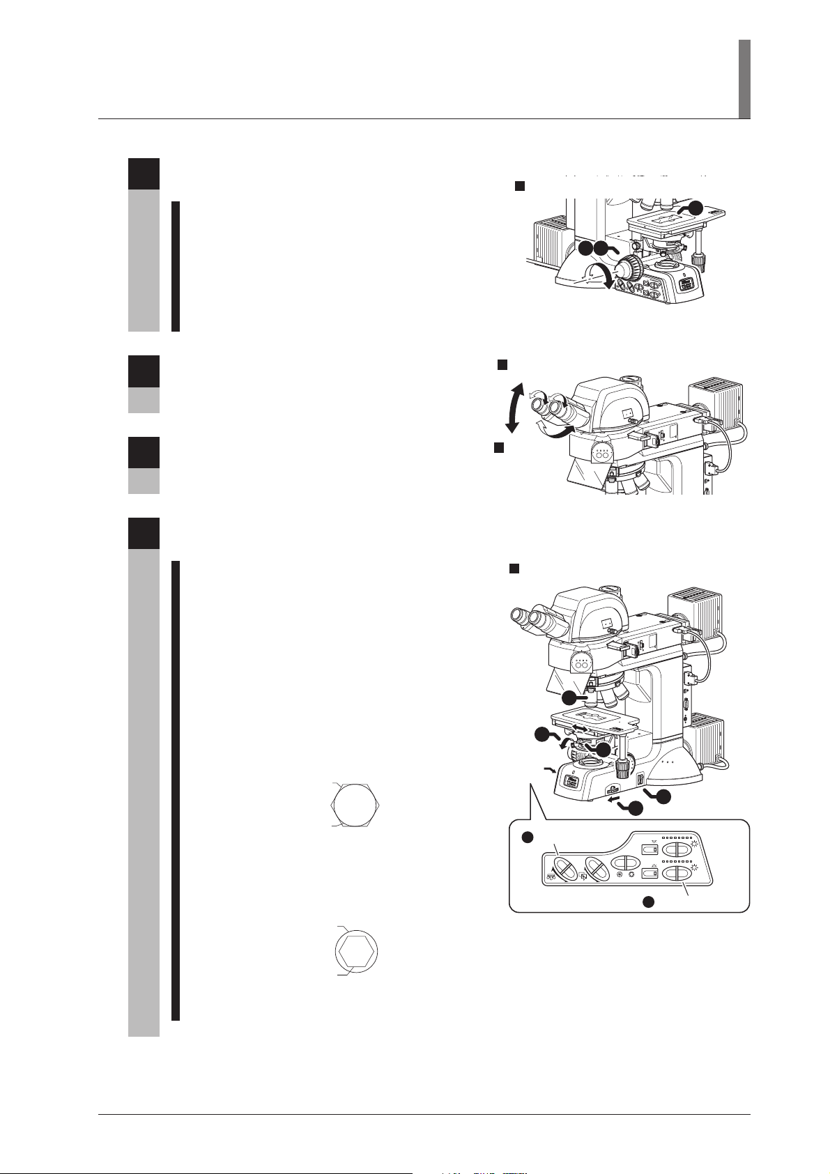
Place the specimen onto the stage and focus
3
on it.
1 Lower the stage by turning the coarse/fine focus
knobs. (See Page 46.)
2 Set the specimen onto the stage.
To use the glass slide, be sure to set the
specimen in place with the cover glass facing up.
3 Turn the coarse/fine focus knobs and focus on
the specimen. (See Page 46.)
II. Microscopy Method
Set the specimen onto the stage and adjust the focus.
3
2
9
.
0
=
2
.
A
.
0
N
r
3
.
ch
0
A
4
0.
0.5
6
.
0
7
0.
1 3
O
B
J
.
0.8
E
P
I
E
P
I
D
I
A
CU
A
B
.
E
S
.
D
I
A
E
G
A
T
N
S
A
P
2
JA
x
3
Adjust the angle of the binocular eyepiece.
4
(for the LV-TT2)
(See Page 48.)
Adjust the diopter and the interpupillary
5
distance.
(See Page 49.)
Set the desired magnification and observe the
6
specimen.
1 Press the OBJ. switch on the operation panel and
locate the objective of desired magnification into
the optical path. (See Page 43.)
2 Turn the coarse/fine focus knobs to bring the
specimen into focus. (See Page 46.)
3 Operate the DIA brightness switch on the
operation panel to adjust the brightness of the
diascopic illumination. (See Page 42.)
4 Use the field diaphragm ring so that the field
diaphragm image circumscribes the field of
view. (See Page 54.)
Image of the
field diaphragm
Field of view
5 Stop down the condenser aperture diaphragm
with the condenser aperture diaphragm ring to
about 70% to 80% of the numerical aperture of
the objective. (See Page 54.)
Adjust the angle of the
4
binocular eyepiece.
OUT
N
I
0
10
0
0
02
10
2
T
T
V
L
J
A
P
A
N
OP
T
S
.
F
BF DF FL1 FL2
BF DF FL1 FL2
FL2
FL1
OUT
IN
100
0
020
10
2
T
T
-
LV
J
A
P
A
N
STOP
.
F
FL2
FL1
Adjust the
5
diopter and the
interpupillary
distance.
6
Change the magnification to observe the specimen.
1
3
x
2
S
J
A
T
P
A
A
N
G
E
0
.8
0
A
chr
.
7
N
.
A
0
=
0
.6
.
9
2
JAPAN
0
.
5
0
.
4
0
.
3
0.2
0.1
5
Operation
panel
B
C
N
8
D
N
.
S
.
F
6
4
OBJ. switch
1
OBJ.
CUBE
EPI
DIA
A.S.
DIA brightness switch
3
UEPI2A
SB
U
C
2
3
2
RS
A
PI2
E
U
USB
C
2
3
2
RS
T
N
C
L
EPI
DIA
Pupil of the objective
Image of the
aperture diaphragm
6 Adjust the brightness with ND filters.
(See Page 44.)
27
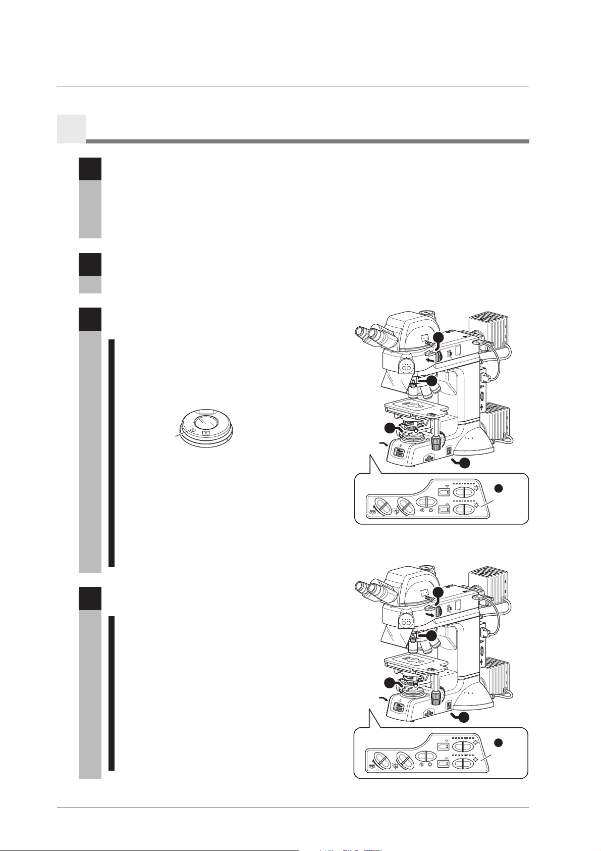
Polarization Microscopy under the Dia Illumination (Simplified/Sensitive Color)
8
Attach the accessories required for the polarization microscopy under the dia illumination.
1
The following accessories must be attached to perform the simplified/sensitive color polarization
microscopy under the dia illumination.
• Diascopic slider (See Page 94.)
• Analyzer slider (See Page 83.)
• Lambda plate holder (for the sensitive color microscopy) (See Page 80.)
Focus on the specimen with the bright-field microscopy under the diascopic
2
illumination.
(See Pages 26, to 27.)
Set the microscope for the polarization
3
microscopy under the diascopic illumination.
1 Push in the analyzer slider to locate the analyzer
into the optical path. (See Page 60.)
2 Locate the polarizer for the diascopic
illumination and make a crossed Nicols position.
BF DF FL1 FL2
OUT
IN
00
1
0
0
02
0
1
T2
T
V
L
1
J
A
P
A
N
STOP
.
F
FL2
FL1
3
(See Pages 58 and 59.)
3
x
2
S
J
A
T
P
A
A
N
G
E
0
.8
0
A
chr
.
7
N
.
A
0
=
0
.6
.
9
JAPAN
0
.
5
0
.
4
0
.
3
0.2
Set the polarizer to the
Swing-out
crossed Nicols position.
center
3 To perform the sensitive color polarization
microscopy, push in the lambda plate slider to
locate the lambda plate into the optical path.
(See Page 63.)
4 Operate the DIA brightness switch on the
Operation
panel
OBJ.
0.1
2
7
5
3
J
7
AP
0
A
N
1
B
C
N
D8
N
.
S
.
F
5
EPI
DIA
A.S.
CUBE
operation panel to adjust the brightness of the
diascopic illumination. (See Page 42.)
5 Adjust the brightness with the ND filter.
(See Page 44.)
EPI
DIA
PI2A
UE
USB
C
2
3
2
RS
T
LCN
4
DIA
brightness
switch
28
Return to the bright-field microscopy under the
4
diascopic illumination.
1 Pull out the analyzer slider and move the analyzer
away from the optical path. (See Page 60.)
2 Move the diascopic polarizer away from the
optical path. (See Pages 58 and 59.)
3 Pull out the lambda plate slider and move the
lambda plate away from the optical path.
(See Page 63.)
4 Operate the DIA brightness switch on the
operation panel to adjust the brightness of the
diascopic illumination. (See Page 42.)
5
Adjust the brightness with ND filters. (See Page 44.)
Operation
panel
OUT
IN
0
0
1
0
20
0
0
1
T2
T
LV-
1
JA
P
A
N
STOP
.
F
BF DF FL1 FL2
FL2
FL1
3
3
x
2
S
J
A
T
P
A
A
N
G
E
0
.
8
0
A
chr
.
7
N
.
A
0
=
0
.6
.
9
JAPAN
0
.
5
0
.
4
0
.
3
0.2
0.1
2
7
5
3
J
7
A
P
0
A
N
1
B
C
N
D8
N
.
S
.
F
EPI
DIA
OBJ.
A.S.
CUBE
A
EPI2
U
USB
2C
3
2
RS
CNT
L
5
4
EPI
DIA
brightness
DIA
switch
 Loading...