

Nikon ECLIPSE L200ND, ECLIPSE L200N Instructions Manual

M513E 09.3.NF.2 (2/4)
IC Inspection Microscope
ECLIPSE L200ND / L200N
Instructions


Introduction
I
IC Inspection Micro scope ECLIPSE L200ND / L200N Instructions
Introduction
Thank you for purchasing a Nikon product.
This instruction manual is written for users of IC Inspection Microscope, ECLIPSE L200ND/L200N.
To ensure correct usage, read this manual carefully before operating the product.
• No part of this manual may be reproduced or transmitted in any form without prior written
permission from Nikon.
• The contents of this manual are subject to change without notice.
• Although every effort has been made to ensure the accuracy of this manual, errors or
inconsistencies may remain. If you note any points that are unclear or incorrect, please contact
your nearest Nikon representative.
• Some of the equipment described in this manual may not be included in the set you have
purchased.
• If you intend to use any other equipment with this product, read the manual for that equipment
too.
• If the equipment is used in a manner not specified by the manufacturer, the protection provided
by the equipment may be impaired.

Safety Precautions
II
IC Inspection Micro scope ECLIPSE L200ND / L200N Instructions
Safety Precautions
To ensure correct and safe operation, read this manual before using the product.
Warning and Caution Symbols Used in This Manual
Although this product is designed and manufactured to be completely safe during use,
incorrect usage or failure to follow the safety instructions provided may cause personal
injury or property damage. To ensure correct usage, read this manual carefully before using
the product. Do not discard this manual and keep it handy for easy reference.
Safety instructions in this manual are marked with the following symbols to highlight their
importance. For your safety, always follow the instructions marked with these symbols.
Table-1 WARNING / CAUTION symbol
Symbol Meaning
WARNING
Disregarding instructions marked with this symbol may lead to serious
injury or death.
CAUTION
Disregarding instructions marked with this symbol may lead to injury or
property damage.
Meaning of Symbol Used on the Equipment
III
IC Inspection Micro scope ECLIPSE L200ND / L200N Instructions
Meaning of Symbol Used on the Equipment
The following symbol placed on the equipment indicates that you need to be cautious when
using the equipment. Before you operate the part of the equipment with this symbol, check
this instruction manual.
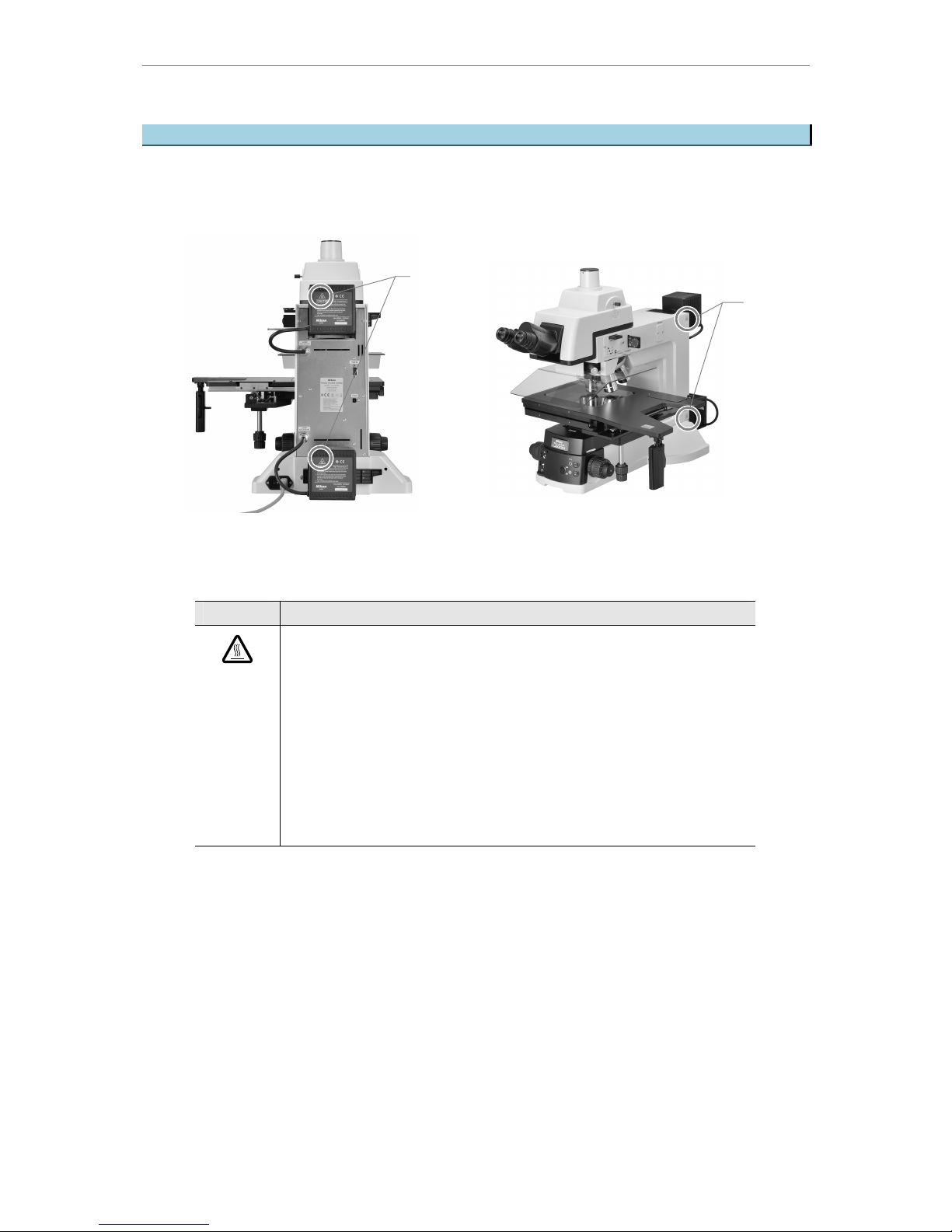
Figure-1 Symbol affixed positions
Table-2 Meaning of symbol
Symbol Meaning
Caution for heat.
This marking on the rear of the lamphouse and the upper and the lower right
of the microscope stand calls your attention on the following:
• Lamphouse becomes extremely hot during and immediately after the
illumination.
• Risk of burns. Do not touch the lamphouse during and immediately after
the illumination.
• Make sure that the lamphouse is sufficiently cool before the lamp
replacement.
Caution
symbol
Caution
symbol

Safety Notes
IV
IC Inspection Micro scope ECLIPSE L200ND / L200N Instructions
Safety Notes
Note the following for safe usage.
WARNING
1 Intended product use
This product should only be used for microscopic observation. Do not use it for any other
purpose. Do not use it to view overly large samples that stick out beyond the stage.
2 Read the instruction manual thoroughly.
For your safety, thoroughly read this instruction manual and the instruction manual of the
equipment used along with this product. Be sure to observe the warnings and cautions
explained in the beginning of this manual.
3 Do not disassemble.
Disassembly may cause malfunction, electrical shock and/or injury. Do not disassemble any
part other than those described in this manual. If you experience any problem with the
microscope, contact your nearest Nikon representative.
4 Power cord
Use only the specified power cord. Using other power cords could result in failures or fire. Also
note that the protection Class 1 equipment should be connected to the PE (protective earth)
terminal for grounding. For details about the specified power cord, see “7 Technical
specifications.”
To prevent electrical shock, always turn off the power switch (flip it to the “c” side) before
connecting or disconnecting the power cord.
5 Heat from the light source
The lamp and the lamphouse become extremely hot. To avoid burns, do not touch the
lamphouse while the lamp is lit or for thirty minutes after it has been turned off.
Further more, in order to avoid the risk of fire, do not place fabric, paper or highly flammable
volatile materials such as gasoline, petroleum benzene, paint thinner or alcohol near the
lamphouse while the lamp is lit or for about thirty minutes after it has been turned off.
The rear of the microscope also becomes hot during use. Although this is not a malfunction,
be careful not to touch it.
6 Reflection
The polished surface of the sample will reflect strong light by the illumination. Do not look at
the illuminated surface for a long time because the strong reflection may hurt your eyes.
7 External light source
For the fluorescent microscopy with the ECLIPSE L200ND/L200N microscope, the light
source brightness of the lamphouse specified in “7. Technical Specifications” may be less than
desired. In this case, an external light source can be used.
For external light source, use the specified C-HGFIE HG Precentered Fiber Illuminator
(motorized type). When attaching the fiber illuminator to the microscope, be sure to connect
them with the RS-232C cable (cross cable) to prevent a flash of light.

Safety Notes
V
IC Inspection Micro scope ECLIPSE L200ND / L200N Instructions
The fiber illuminator can be used on the L200ND microscope, but not on the L200N
microscope.
Please note that if a light source not specified for the L200ND microscope is attached on the
microscope, the microscope will not be considered as a TUV/SEMI-approved product.
8 Ultraviolet light from an external light source (including those not specified)
If you use a light source other than those specified, and if the light source has a mercury lamp,
etc., the light source radiates ultraviolet light from the emission port. The ultraviolet light is
harmful to the eyes and skin. Direct viewing of such light may result in a minor eye injury such
as snow blindness, or, in a worst case, may result in a serious eye injury that could lead to
blindness. To prevent injury, follow the guidelines below.
1) Insert the UV collector lens into the optical path of the microscope unless the UV excitation
light is necessary.
On the ECLIPSE L200ND/L200N microscope, the UV filter automatically enters the optical
path when turning the dark-field/bright-field/fluorescent selection lever to BF (bright-field)
or DF (dark-field). The UV filter is removed from the optical path when turning the lever to
FL (Fluorescent).
2) When performing the fluorescent microscopy by using the UV excitation light, attach the
filter block dedicated to the UV excitation light. And then, if you must see the objective or
its surroundings, be sure to see through the breath shielding plate (ultraviolet light shield).
3) Attach the light source to the microscope during use.
Always attach the light source to the microscope when the light source is ready to turn on.
Do not turn on the light source unattached to the microscope, or remove the light source
from the microscope while the light source is lit. When removing the light source from the
microscope, turn off the power to the light source, and then unplug the power cord from the
wall outlet.

Safety Notes
VI
IC Inspection Micro scope ECLIPSE L200ND / L200N Instructions
CAUTION
1 Disconnect this product from the power supply before assembling this product, attaching or
removing the cord, replacing the lamp, or performing maintenance.
To prevent electric shocks and failures, when you assemble this product, attach or remove the
cord, replace the lamp, or clean the main body or objectives, you must turn off this product
and other related equipment (flip the power switches to the “c” side) and unplug the power
cords from the wall outlet.
2 Check the light source.
Use only the specified lamp and the lamphouse on this product. The use of other lamps and
lamphouses may lead to malfunction. For details about the specified lamp and lamphouse,
see “7 Technical specifications.”
3 Cautions on lamp replacement
• To prevent burn injury, allow the lamp to cool for at least 30 minutes after turning off the
power switch, before replacing the lamp.
• To prevent electrical shock and damage to the microscope, always turn off the power
switch (flip it to the “c” side) and unplug the power cord from the wall outlet before
connecting or disconnecting the lamphouse.
• Do not touch the glass surface of the lamp with bare hands. Fingerprints or grease on the
bulb surface will reduce the illumination of the lamp. Wipe clean the fingerprints or grease
with a clean piece of cloth.
• Securely attach the lamphouse cover to the lamphouse after replacing the lamp. Never
light the lamp while the lamphouse cover is open.
• When you dispose of the replaced lamp, do not shatter it or dispose of it casually. Dispose
of the used lamp as the special industrial waste or dispose of them according to the
regulations and rules of your local authority.
4 Do not let the microscope become wet.
Do not get this product wet. In addition, do not use this product in an environment where water
will get into this product. If the product gets wet, a short circuit may result that may cause
malfunction or abnormal heating of the product. If you accidentally spill a liquid on the
microscope, immediately turn off the power switch (flip it to the “c” side) and unplug the power
cord from the wall outlet. Then use a dry cloth to wipe away the moisture. If any liquid gets
inside the microscope, do not use it; instead, notify your nearest Nikon representative.
5 Weak electromagnetic emission
This product emits weak electromagnetic waves. The accuracy of any precision electronic
equipment may be adversely affected if positioned too close. If the microscope affects TV or
radio reception, move the radio or TV further away from the microscope.
6 Installation location
This product is a precision optical instrument. Using or storing the microscope under
unsuitable conditions may damage it or may have an adverse effect on its accuracy. The
following conditions should be kept in mind when selecting the installation location.
• Avoid a brightly lit location such as a room that receives direct sunlight, or directly under
room lights. If there is excessive ambient light, image may not clearly be visible.
• Choose a location that is free from dust or dirt.

Safety Notes
VII
IC Inspection Micro scope ECLIPSE L200ND / L200N Instructions
• Choose a flat surface with little vibration.
• Choose a sturdy desk or table that is able to bear the weight of the instrument.
• The main body of this instrument weighs about 30 kg.
To install this instrument on a desk or a table, at least two people are required. Handle the
instrument carefully and do not drop it. Dropping may injure the person carrying it or
damage the instrument.
• Install this product in a place where it will not be a hazard in case of an unexpected event
such as an earthquake. In some locations, you may need to tie down this product to a
workbench or secure object so that it will not overturn or fall down.
• Do not use this microscope in an environment where water can get into the microscope.
• Do not install the microscope in a warm, humid location.
• Install this microscope in a location where you can easily unplug the power cord from the
AC inlet of this microscope in emergency.
• Provide enough space around the microscope referring to the layout diagrams on the next
page.
• The installation conditions are as follows:
Area required : 710 mm (W) × 940 mm (D) or more (see the layout diagrams)
Power source : 100 to 240 V AC ±10% (1.2 A)
Humidity : Relative humidity 85% at maximum (no condensation)
Operating environmental temperature : +5° to +35°C
Weight of the microscope : 45 kg (including stage and eyepiece tube) approx.
7 Cautions on moving the microscope
• The microscope is a precision optical instrument. Handle it carefully and do not subject it to
a strong physical shock.
• When moving the microscope, first remove the stage. Then, have two or more people
grasp the microscope from both sides.
(Information) The main body of the L200ND/L200N weighs about 30 kg.
With the eyepiece tube, lamphouse and other parts (except stage)
attached, the microscope weighs about 35 kg.
• Do not grasp the focusing knobs, eyepiece tube, lamphouse, stage mount, breath shielding
plate, etc., when carrying the microscope. They may come off and may cause serious
injury or malfunction.
• Ask your nearest Nikon representative for the carrying rods of the microscope.
• Before carrying the stage, attach the two fixing metals to hold the movement of the stage
plate. Use the smaller fixing metal to secure the side of the stage and then use the larger
fixing metal to secure the front of the stage.
• Be careful not to pinch your fingers or hands when moving the microscope.
8 Cautions on assembling the microscope
• Be careful not to pinch your fingers or hands during the assembly.
• The scratches or fingerprints on the lens surface will adversely affect the microscope's
image. Be careful not to scratch or touch the lens surfaces.
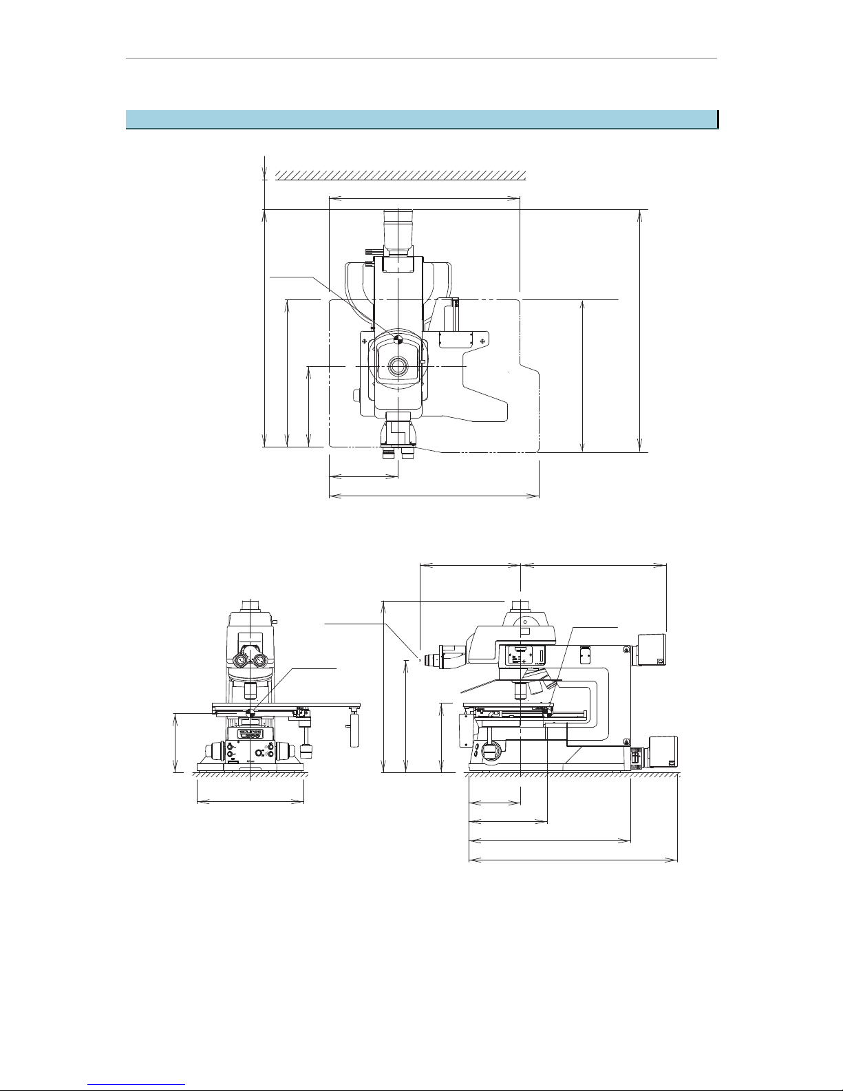
Layout Diagram
VIII
IC Inspection Micro scope ECLIPSE L200ND / L200N Instructions
Layout Diagram
Gravity point
<Operator space>
234
710 (Stage movable range)
280
496
810 (Stage movable range)
645 (Stage movable range)
100
Gravity point
Gravity point
Eye point
175
360
266
244
379-493.5
339
200
547
580
704
515
829 (Stage movable range)
490
Dimensions are in mm.
Figure-2 Layout diagram
Operating Posture
IX
IC Inspection Micro scope ECLIPSE L200ND / L200N Instructions
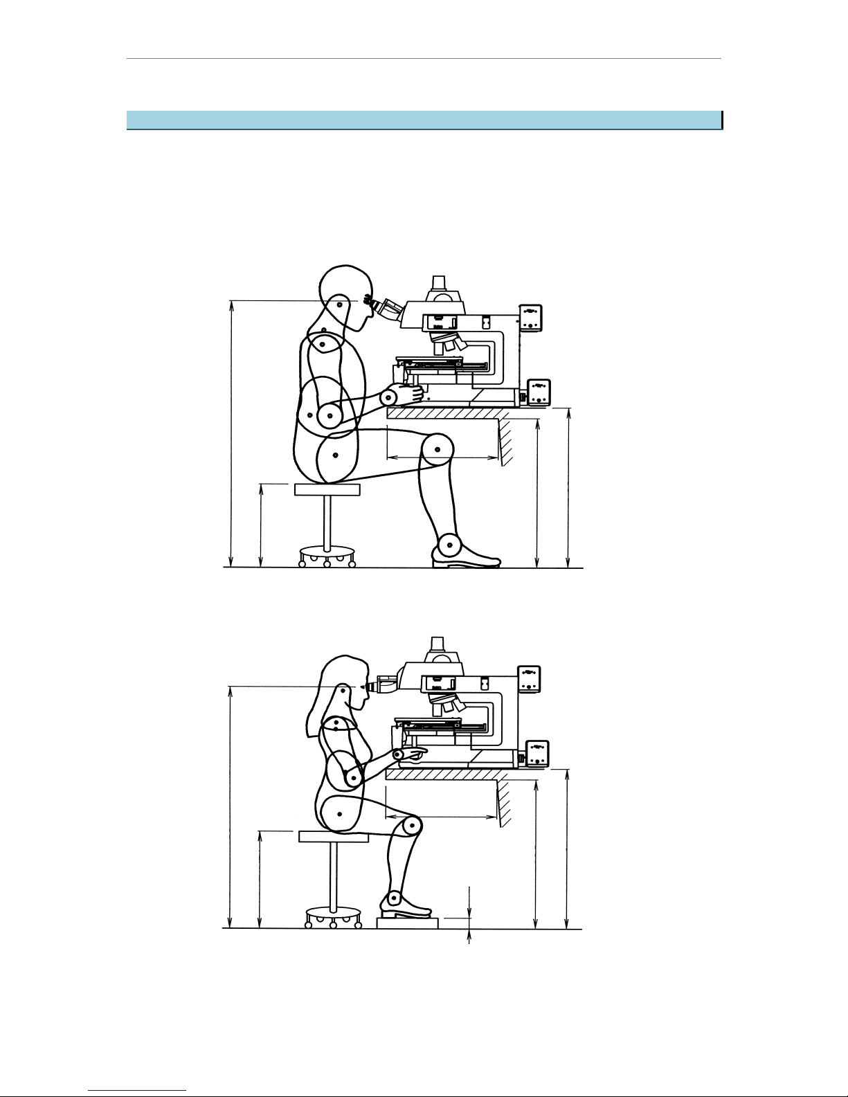
Operating Posture
The figure below shows the posture that prevents strain on your body when you operate this
equipment.
Choose a workbench and a chair having the similar dimensions to those shown on the
figure.
510
The 5th percentile female (Height: 1475 mm)
(The front
clearance for
the knees)
405 (The height of the seating surface)
1253 (The height of the eye point)
510
1138 (The height of the eye point)
690
470 (The height of the seating surface)
760
The 95th percentile male (Height: 1895 mm)
760
690
(The height of the workbench)
(The upper clearance
for the knees)
70
(The height of the workbench)
(The front clearance
for the knees)
(The upper clearance
for the knees)
Dimensions are in mm.
Figure-3 Operating posture

Contents
X
IC Inspection Micro scope ECLIPSE L200ND / L200N Instructions
Introduction ......................................................................................................................... I
Safety Precautions ............................................................................................................. II
Meaning of Symbol Used on the Equipment..................................................................... III
Safety Notes...................................................................................................................... IV
Layout Diagram............................................................................................................... VIII
Operating Posture .............................................................................................................IX
1 Names of the Parts................................................................................ 1
1.1 Names of the parts.................................................................................................... 1
1.2 Names of the operational parts................................................................................. 2
2 Microscopy ............................................................................................ 4
2.1 Episcopic bright-field microscopy ............................................................................. 5
2.2 Episcopic dark-field microscopy ............................................................................... 6
2.3 Episcopic DIC (differential interference contrast) microscopy .................................. 7
2.4 Episcopic bright-field simplified polarization microscopy.......................................... 8
2.5 Episcopic fluorescent microscopy (for L200ND only) ............................................... 9
2.6 Diascopic bright-field microscopy (for L200ND only).............................................. 10
3 Operation of Each Part .........................................................................11
3.1 Filters .......................................................................................................................11
3.1.1 The types and usage of the filters ............................................................................ 11
3.1.2 Placing the filter in and out of the optical path (for episcopic illumination) ............... 12
3.1.3 Placing the filter in and out of the optical path (for diascopic illumination) ............... 12
3.2 Coarse / fine focus knobs ....................................................................................... 13
3.2.1 The relationship between the focus knob rotation and the stage vertical
movement ................................................................................................................ 13
3.2.2 Adjusting the torque of the coarse focus knobs .......................................................13
3.2.3 Coarse focus stopper ring........................................................................................ 14
3.3 Eyepiece tube ......................................................................................................... 15
3.3.1 Optical path selection............................................................................................... 15
3.3.2 Tilting function.......................................................................................................... 15
3.3.3 Vertical tube adapters ..............................................................................................15
3.4 Diopter adjustment.................................................................................................. 16
3.5 Interpupillary distance adjustment .......................................................................... 17

Contents
XI
IC Inspection Micro scope ECLIPSE L200ND / L200N Instructions
3.6 Aperture diaphragm ................................................................................................ 17
3.6.1 Adjusting the size of the aperture diaphragm........................................................... 17
3.6.2 Centering the episcopic aperture diaphragm ...........................................................18
3.7 Changing the illumination ....................................................................................... 19
3.8 8 × 8 Stage.............................................................................................................. 20
3.8.1 The coarse mode..................................................................................................... 20
3.8.2 The fine mode.......................................................................................................... 21
3.9 Focusing target ....................................................................................................... 21
3.9.1 How to use the focusing target................................................................................. 21
3.10 Motorized nosepiece............................................................................................... 22
3.11 Polarizer slider ........................................................................................................ 22
3.11.1 Attaching the polarizer slider.................................................................................... 22
3.11.2 Placing/removing the polarizer in/from the optical path............................................ 23
3.11.3 Adjusting the orientation of the polarizer.................................................................. 23
3.12 Analyzer slider ........................................................................................................ 24
3.12.1 Attaching the analyzer slider .................................................................................... 24
3.12.2 Placing/removing the analyzer in/from the optical path............................................ 24
3.13 DIC slider ................................................................................................................ 25
3.13.1 Attaching (removing) the DIC slider ......................................................................... 25
3.13.2 Placing/removing the DIC prism in/from the optical path..........................................25
3.13.3 Selecting the DIC prism position.............................................................................. 26
3.13.4 Setting the interference color ................................................................................... 26
3.14 Pinhole slider .......................................................................................................... 27
3.14.1 Attaching the pinhole slider ...................................................................................... 27
3.14.2 Placing/removing the pinhole in/from the optical path.............................................. 27
3.14.3 Centering the pinhole............................................................................................... 28
3.15 L200ND EPI/DIA simultaneous illumination............................................................ 28
4 Assembly ............................................................................................. 30
4.1 Required tools......................................................................................................... 30
4.2 Installation location ................................................................................................. 31
4.3 System diagram ...................................................................................................... 32
4.4 Attaching the lamphouse and replacing the lamp................................................... 33
4.4.1 Attaching the lamphouse..........................................................................................33
4.4.2 Replacing the lamp ..................................................................................................34
4.4.3 Attaching the fiber adapter and external light source............................................... 35
4.5 Attaching the stage and the holder ......................................................................... 38
4.6 Attaching the eyepiece tube.................................................................................... 38
4.6.1 When removing the eyepiece tube...........................................................................38
4.7 Attaching the objectives .......................................................................................... 39

Contents
XII
IC Inspection Micro scope ECLIPSE L200ND / L200N Instructions
4.7.1 When removing the objectives................................................................................. 39
4.7.2 If the objectives are out of the optical path when they are switched ........................39
4.8 Attaching the eyepieces.......................................................................................... 39
4.9 Installing the filter block (for fluorescent illumination only) ..................................... 39
4.10 Attaching breath shielding plate (ultraviolet light shield)......................................... 40
4.11 Seismic restraint ..................................................................................................... 41
4.12 Connecting the power cord..................................................................................... 42
4.13 Attaching a camera ................................................................................................. 42
4.13.1 LV-TV TV adapter/C-mount adapter......................................................................... 42
4.13.2 TV cameras.............................................................................................................. 42
4.13.3 Digital cameras ........................................................................................................43
4.14 Setting the Dip switch on the L200ND/L200N main body....................................... 44
4.15 Communications control ......................................................................................... 45
4.15.1 Connecting external devices.................................................................................... 45
4.15.2 Control options and status displays on a PC or the DS-L2 ......................................46
4.15.3 Registering information on the objective .................................................................. 47
4.15.4 Procedure for turning on the power switch............................................................... 47
5 Troubleshooting ................................................................................... 48
5.1 Viewing and control systems .................................................................................. 48
5.2 Electrical ................................................................................................................. 52
6 Care and Maintenance ........................................................................ 53
6.1 Daily care and maintenance ................................................................................... 53
6.2 Cleaning the lens .................................................................................................... 53
6.2.1 Cleaning tool and supplies (consumables)............................................................... 54
6.2.2 Cleaning procedure and notes................................................................................. 54
6.3 Cleaning this equipment ......................................................................................... 54
6.4 Storage.................................................................................................................... 54
6.5 Regular inspections (with charge) .......................................................................... 54
7 Technical Specifications....................................................................... 55
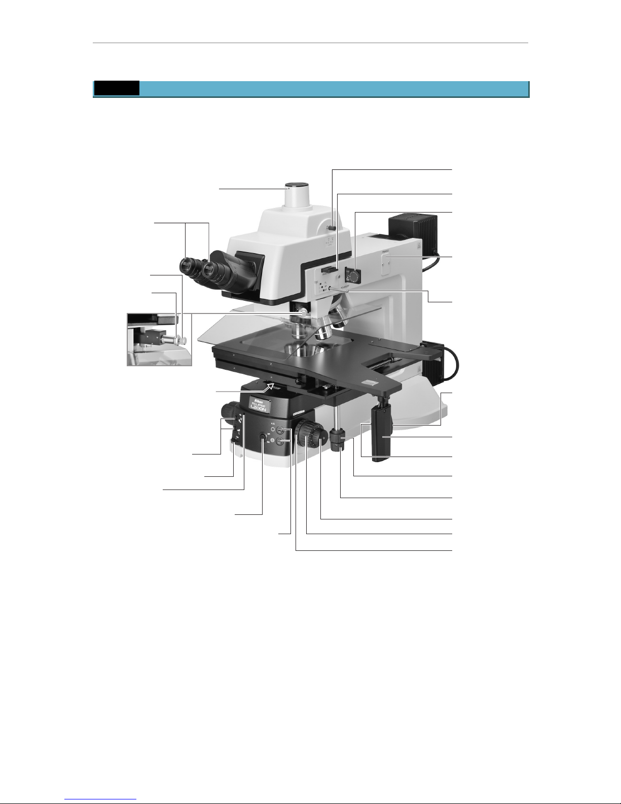
1 Names of the Parts
1
IC Inspection Micro scope ECLIPSE L200ND / L200N Instructions
1
Names of the Parts
1.1 Names of the parts
Eyepiece tube
Eyepieces
Microscope arm
Microscope main
body
Episcopic
lamphouse
Analyzer slider *
1
Polarizer slider *
1
Attaching part for
the pinhole slider *
2
Breath shielding
plate
Revolving
nosepiece
DIC slider *
3
Objective
Stage
Sample holder
(The glass plate is used
in this figure.)
Microscope base
Diascopic
lamphouse
(for L200ND only)
*1: For DIC microscopy or episcopic bright-field simplified polarization microscopy
*2: For pinhole microscopy, insert the pinhole slider here.
*3: For DIC microscopy
Figure-4 Names of the parts
1 Names of the Parts
2
IC Inspection Micro scope ECLIPSE L200ND / L200N Instructions
1.2 Names of the operational parts
Analyzer slider *
1
Polarizer slider *
1
Attaching part for
the pinhole slider *
2
Prism
movement knob
Clamp for various adapters
Optical path
selection lever
Diopter
adjustment rings
Dark -field/brightfield/fluorescent
selection lever
(for L200ND only)
(Dark-field/brightfield selection
lever for L200N)
Aperture diaphragm lever
for diascopic illumination
(for L200ND only)
(The lever is found
under the substage.)
Fine focus knob
Coarse focus knob
Coarse torque
adjustment ring
Stage fine movement
knob for Y-axis
Stage fine movement
knob for X-axis
Stage coarse
movement lever
Coarse movement
ON switch
Coarse movement
OFF switch
Episcopic/Diascopic illumination
selection switch
Episcopic aperture diaphragm control buttons
Nosepiece rotation
buttons
Brightness control dial
Pilot lamp
(Lights when the power is ON.)
DIC slider *
3
Prism
selection
knob
*1: For DIC microscopy or episcopic bright-field simplified polarization microscopy
*2: For pinhole microscopy, insert the pinhole slider here.
*3: For DIC microscopy
Figure-5 Names of the operational parts (1)
1 Names of the Parts
3
IC Inspection Micro scope ECLIPSE L200ND / L200N Instructions
Focusing target lever
Filter sliders
Aperture diaphragm
centering screw holes
Screw hole for carrying rod
Screw holes for AF drive
Slots for diascopic illumination
filter (for L200ND only)
Coarse focus stopper ring
Filter sliders
Figure-6 Names of the operational parts (2)
“Caution for heat” symbol
CAUTION label
Connector for
episcopic lamphouse
Connector for
diascopic lamphouse
Power cord
AC IN connector
Power switch
Input voltage indication
Screw holes for carrying
rods
USB connector
(For connecting a PC or
the DS-L2 digital camera)
HGFIE connector
(For connecting the
C-HGFIE HG Precentered
Fiber Illuminator (motorized
type))
Figure-7 Names of the operational parts (3)

2 Microscopy
4
IC Inspection Micro scope ECLIPSE L200ND / L200N Instructions
2
Microscopy
In this chapter, each type of microscopy is described.
Please also refer to “3 Operation of Each Part” for how to operate each part.
1. Episcopic bright-field microscopy --------------------------------------------------------------------- p.5
2. Episcopic dark-field microscopy ----------------------------------------------------------------------- p.6
3. Episcopic DIC (differential interference contrast) microscopy---------------------------------- p.7
4. Episcopic bright-field simplified polarization microscopy ---------------------------------------- p.8
5. Episcopic fluorescent microscopy (for L200ND only) -------------------------------------------- p.9
6. Diascopic bright-field microscopy (for L200ND only) --------------------------------------------p.10
2 Microscopy
5
IC Inspection Micro scope ECLIPSE L200ND / L200N Instructions
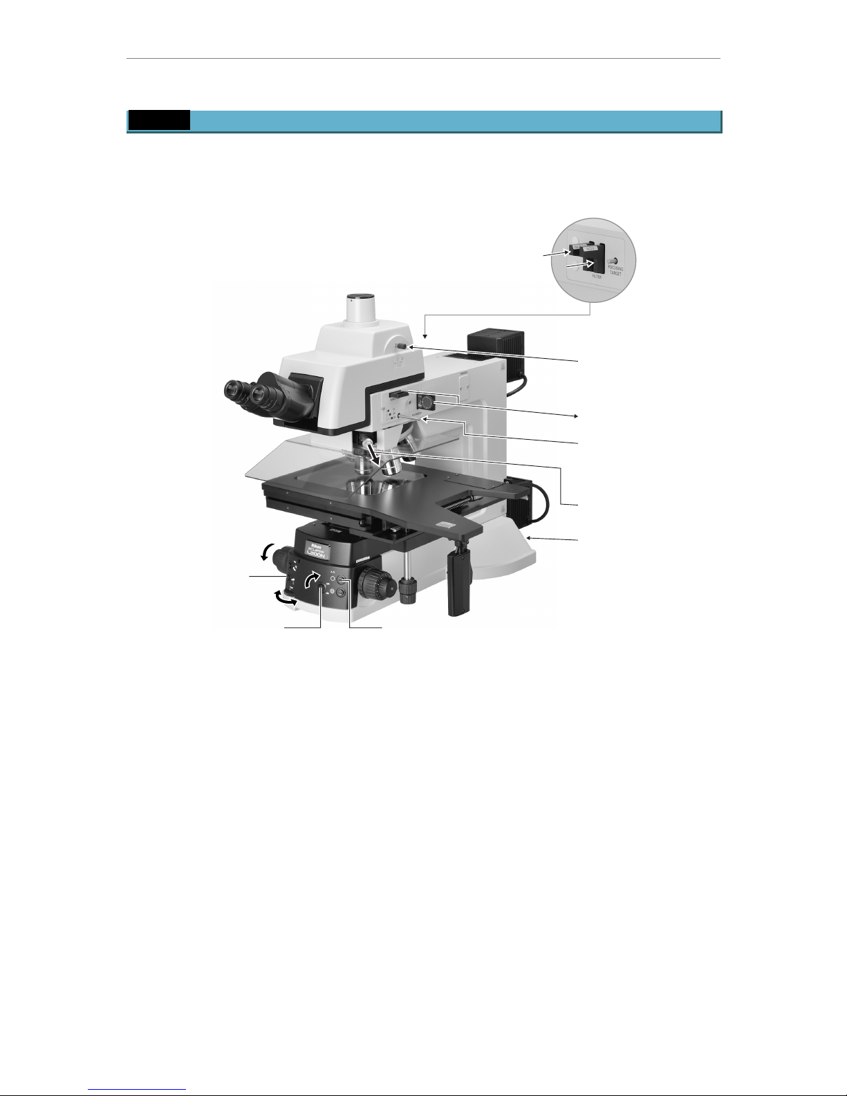
2.1 Episcopic bright-field microscopy
1.
Set each part as follows.
Í
You can perform steps in any sequence.
Press in the NCB and ND filters.
(Insert the NCB filter into the
nearest slot to the lamphouse.)
Press in for 100% binocular
observation.
Slide out the analyzer and
the polarizer.
Press in for BF (bright-field).
(For L200ND, press in to the
limit and then pull to the first
click-stop position for BF.)
Turn ON the power.
Fully open the aperture diaphragm.Press for EPI.
(For L200ND only)
Adjust brightness.
Select 10×
objective.
Lower the stage
to the limit.
Slide out the DIC slider.
2.
Place the sample on the stage. ---------------------------------------------------See “3.8 8 × 8 Stage”
Í
Move the stage to your right (or left) side.
3.
Focus on the sample. ----------------------------------- See “3.8 8
×
8 Stage” and “3.9 Focusing target”
Í
Use the focusing target for a sample with a polished surface.
4.
Adjust diopter.-----------------------------------------------------------------See “3.4 Diopter adjustment”
5.
Adjust interpupillary distance.----------------------------- See “3.5 Interpupillary distance adjustment”
6.
Switch to the desired objective and focus on the sample again.
7.
Adjust brightness.------------------------------------------------------------------------- See “3.1 Filters”
Í
Use the ND filters and brightness control dial.
8.
Adjust the size of the aperture diaphragm. ---------------------------See “3.6 Aperture diaphragm”
2 Microscopy
6
IC Inspection Micro scope ECLIPSE L200ND / L200N Instructions
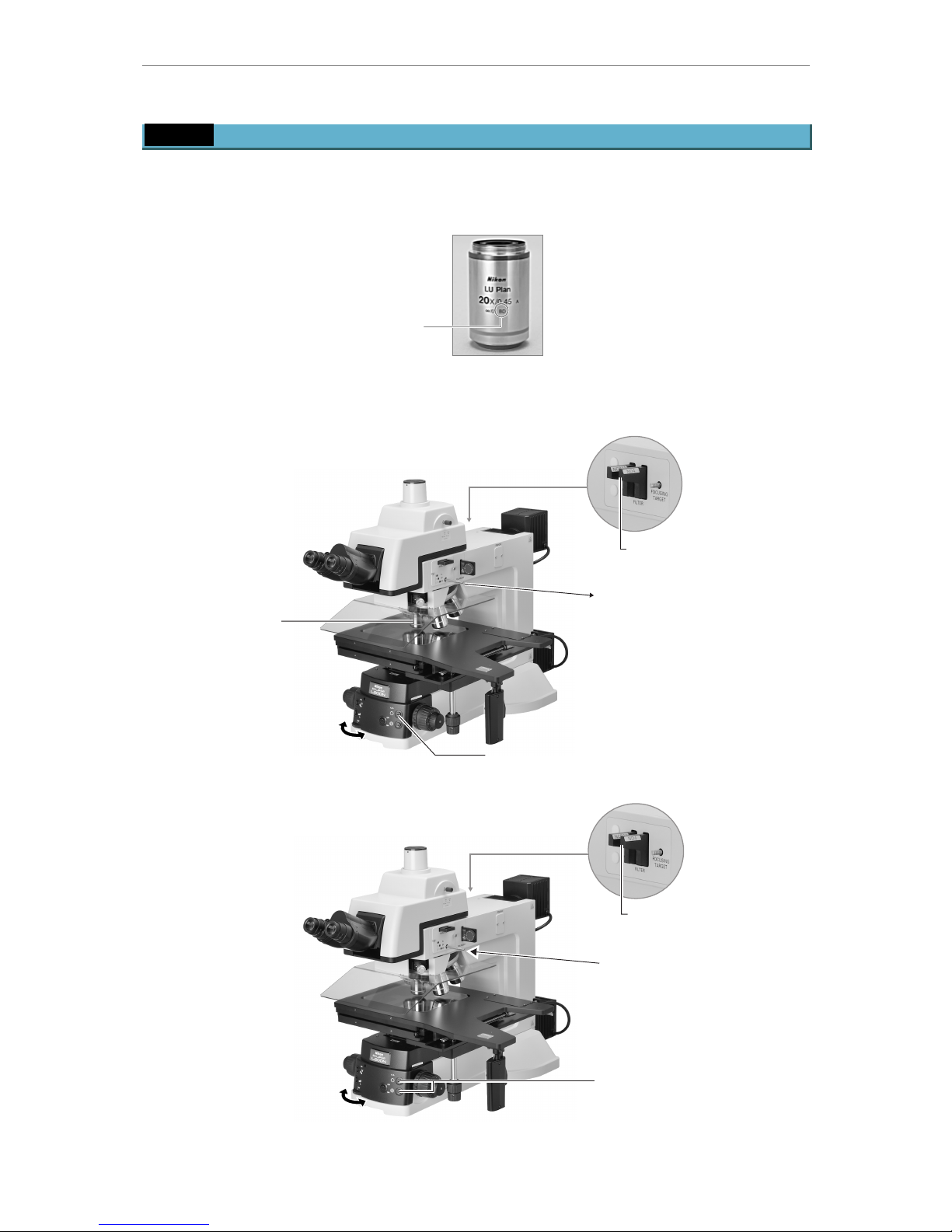
2.2 Episcopic dark-field microscopy
1.
Mount the BD objectives.
Í
However, only the objectives marked “BD” can be used on the dark-field microscopy.
2.
Observe the sample by following the steps for the episcopic bright-field microscopy.
---------------------------------------------------------------------
See “2.1 Episcopic bright-field microscopy”
3.
Switch to the dark-field microscopy.
Adjust brightness
with the ND filters.
Slide out for DF (dark-field).
(For L200ND, pull out to
the limit for DF.)
Fully open the aperture diaphragm.
Adjust brightness
with the brightness
control dial.
Swing in
the BD objective.
4.
After dark-field microscopy, return to bright-field microscopy, if required.
Adjust the size of the aperture
diaphragm.
Adjust brightness
with the ND filters.
Press in for BF (bright-field).
(For L200ND, press in to the
next click-stop position for BF.)
Adjust brightness
with the brightness
control dial.
BD marking on the objective
2 Microscopy
7
IC Inspection Micro scope ECLIPSE L200ND / L200N Instructions
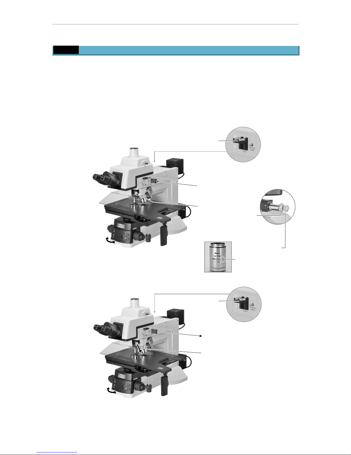
2.3 Episcopic DIC (differential interference contrast) microscopy
1.
Attach the analyzer, polarizer and DIC sliders.
Í
Slide them out to the click-stop position.
2.
Observe the sample by following the steps for the episcopic bright-field microscopy.
-------------------------------------------------------------------
See “2.1 Episcopic bright-field microscopy”
3.
Switch to the DIC microscopy.
Í
The objective with “LU” marking is suitable for DIC microscopy.
Adjust brightness
with the ND filters.
Press in the polarizer and
the analyzer.
Adjust brightness
with the brightness
control dial.
Press in the DIC slider.
Rotate the knob to the
position indicated on the
objective.
(For the objective shown
below, turn the knob to match
the leter “A” with the white dot.)
Prism position indication
on the objective
Rotate to change
the background color.
4.
After DIC microsopy, return to bright-field microscopy, if required.
Adjust brightness
with the ND filters.
Slide out the polarizer and analyzer.
Slide out the DIC slider.
Adjust brightness
with the brightness
control dial.
 Loading...