

Page 1

Radius CM200
™
/
CM300
™
& Motorola PM400
™
Commercial Series
Mobile Radio Basic Service Manual
Page 2

Page 3

CM200/CM300/PM400
Radios
i
Basic Service Manual
6802966C15-A
Issue: August, 2004
Page 4

ii
Foreword
This manual is intended for use by service technicians familiar with similar types of equipment. It contains
service information required for the equipment described and is current as of th e printing date. Changes which
occur after the printing date may be incorporated by a complete Manual revision or alternatively as additions.
Note:
Before operating or testing these units, please read the Product Safety and RF Exposure
Compliance section.
Computer Software Copyrights
The Motorola products described in this manual may include copyrighted Motorola computer prog r ams stor ed
in semiconductor memories or other media. Laws in the United States and other countries preserve for
Motorola certain exclusive rights for copyrighted computer programs, including , but not limited to, the
exclusive right to copy or reproduce in any form the copyrighted computer program. Accordingly, any
copyrighted Motorola computer programs contained in the Motorola products described in this manual may
not be copied, reproduced, modified, reverse-engineered, or distributed in any manner without the express
written permission of Motorola. Furthermore, the purchase of Motorola products shall not be deemed to grant
either directly or by implication, estoppe l, or otherwise, any license under the copyrights, patents or patent
applications of Motorola, except for the normal non-exclusive license to use that arises by operation of law in
the sale of a product.
Document Copyrights
No duplication or distribution of this document or any portion thereof shall take place without the express
written permission of Motorola. No part of this manual may be reproduced, distributed, or transmitted in any
form or by any means, electronic or mechanical, for any purpose without the express written permission of
Motorola.
Disclaimer
The information in this document is carefully examined, and is believed to be entirely reliable. However, no
responsibility is assumed for inaccuracies. Furthermore, Motorola reserves the right to make changes to any
products herein to improve readability, function, or design. Motorola does not assume any liability arising out
of the applications or use of any product or circuit described herein; nor does it cover any license under its
patent rights nor the rights of others.
MOTOROLA, The Stylized M logo, and Radius are trademarks of Motorola, Inc.
All other product or servic e na m es are the property of their respective owners.
© 2004 Motorola, Inc. All rights reserved. Printed in U.S.A.
Page 5

Table of Contents
Foreword......................................................................................................................... ii
Computer Software Copyrights....................................................................................... ii
Document Copyrights ..................................................................................................... ii
Disclaimer ....................................................................................................................... ii
Product Safety and RF Exposure Compliance ..............................................................vii
Chapter 1 INTRODUCTION
1.0 Scope of Manual ..................................................................................................1-1
2.0 Warranty and Service Support.............................................................................1-1
2.1 Warranty Period and Return Instructions ....................................................1-1
2.2 After Warranty Period..................................................................................1-1
3.0 Replacement Parts Ordering ............................................................................... 1-2
3.1 Basic Ordering Information..........................................................................1-2
3.2 Motorola Online ...........................................................................................1-2
3.3 Mail Orders..................................................................................................1-2
3.4 Telephone Orders .......................................................................................1-2
3.5 Fax Orders .................................................................................................. 1-2
3.6 Parts Identification.......................................................................................1-3
4.0 Radio Model Information......................................................................................1-3
iii
Chapter 2 MAINTENANCE
1.0 Introduction ..........................................................................................................2-1
2.0 Preventive Maintenance ......................................................................................2-1
2.1 Inspection ....................................................................................................2-1
2.2 Cleaning Procedures...................................................................................2-1
3.0 Safe Handling of CMOS and LDMOS Devices ....................................................2-2
4.0 Repair Procedures and Techniques — General ..................................................2-3
5.0 Disassembling and Reassembling the Radio — General ....................................2-3
6.0 Radio Disassembly - Detailed..............................................................................2-4
6.1 Control Head Removal ................................................................................2-4
6.2 Top Cover Removal ....................................................................................2-6
6.3 Main Shield Removal ..................................................................................2-7
6.4 PA Shield and DC Cable Removal..............................................................2-7
6.5 PA Clip and Main PCB Removal (for Low Power Models) ..........................2-8
6.6 Main PCB Removal (for High Power Models) ............................................. 2-9
6.7 Disassembly of Control Head - CM200 .....................................................2-10
6.8 Disassembly of Control Heads - CM300/PM400....................................... 2-11
7.0 Radio Assembly.................................................................................................2-12
7.1 Chassis Assembly (for Low Power Models) ..............................................2-12
7.2 Chassis Assembly (for High Power Models) .............................................2-12
Page 6

iv
7.3 Control Heads Assembly...........................................................................2-13
7.4 Control Head Fitting .................................................................................. 2-13
7.5 Option Board Installation...........................................................................2-14
8.0 Radio Exploded Mechanical Views and Parts Lists........................................... 2-15
8.1 Radio Assembly - 1-25 W Models .............................................................2-15
8.2 Radio Assembly - 25-40 W/25-45 W Models ............................................2-16
8.3 Control Head - CM200 .............................................................................. 2-17
8.4 Control Head - CM300/PM400 ..................................................................2-18
9.0 Service Aids.......................................................................................................2-19
10.0 Test Equipment..................................................................................................2-20
11.0 Programming/Test Cable - RKN4083_ .............................................................. 2-21
12.0 Adapter Cable - FKN8113_ ...............................................................................2-22
Chapter 3 TRANSCEIVER PERFORMANCE TESTING
1.0 General ................................................................................................................3-1
2.0 Setup ................................................................................................................... 3-1
3.0 RF Test Mode ......................................................................................................3-2
Chapter 4 RADIO TUNING AND PROGRAMMING
1.0 Introduction ..........................................................................................................4-1
2.0 CPS Programming/Flashing Setup with RIB .......................................................4-1
3.0 CPS Programming/Flashing Setup Ribless ......................................................... 4-2
4.0 CPS Programming Setup with RIB (with Telco Connector)................................. 4-2
5.0 CPS Programming Setup with RIB (Accessory Connector) ................................4-3
6.0 CPS Programming Setup with RIB ...................................................................... 4-3
7.0 Radio Tuning Setup .............................................................................................4-4
7.1 Initial Test Equipment Control Settings .......................................................4-4
Chapter 5 POWER UP SELF-TEST
1.0 Error Codes ......................................................................................................... 5-1
Chapter 6 ACCESSORIES & CONNECTOR PIN FUNCTIONS
1.0 Accessories ......................................................................................................... 6-1
1.1 Antennas ..................................................................................................... 6-1
1.2 Audio ........................................................................................................... 6-2
1.3 Alarms and Accessories..............................................................................6-2
1.4 Control Station.............................................................................................6-3
1.5 Public Address ............................................................................................ 6-3
1.6 Cables ......................................................................................................... 6-3
1.7 Mounting......................................................................................................6-3
1.8 Data - CES Wireless Technologies .............................................................6-4
Page 7

1.9 Peripherals ..................................................................................................6-4
2.0 Accessory Connector Pin Function......................................................................6-5
3.0 Microphone Connector Pin Function....................................................................6-6
Chapter 7 MODEL CHART AND TEST SPECIFICATION
1.0 Low Power Radios ...............................................................................................7-1
1.1 146-174 MHz CM200/CM300/PM400 Model Chart.....................................7-1
1.2 438-370 MHz CM200/CM300/PM400 Model Chart.....................................7-2
1.3 Specifications .............................................................................................7-3
2.0 High Power Radios .............................................................................................. 7-5
2.1 136-162 MHz CM300 Model Chart..............................................................7-5
2.2 146-174 MHz CM200/CM300/PM400 Model Chart.....................................7-5
2.3 438-470 MHz CM200/CM300/PM400 Model Chart.....................................7-6
2.4 465-495 MHz PM400 Model Chart..............................................................7-7
2.5 Specifications .............................................................................................7-8
3.0 MIL Standards....................................................................................................7-10
v
GLOSSARY ...................................................................................... G-i
Page 8

vi
THIS PAGE INTENTIONALLY LEFT BLANK
Page 9

SAFETY INFORMATION
!
Product Safety and RF Exposure Compliance
Note:
Before using this product, read the operating instructions for safe usage contained in the
Product Safety and RF Exposure booklet enclosed with your radio.
C a u t i o n
ATTENTION!
This radio is restricted to occupational use only to satisfy FCC RF energy exposure requirements.
Before using this product, read the RF energy awareness information and operating instructions in the
Product Safety and RF Exposure booklet enclosed with your radio (Motorola Publication part number
68P81095C99) to ensure compliance with RF energy exposure limits.
For a list of Motorola-approved antennas, batteries, and other accessories, visit the following web site which
lists approved accessories: http://www.motorola.com/cgiss/index.shtml.
vii
Page 10

viii
THIS PAGE IS INTENTIONALLY BLANK
Page 11

1.0 Scope of Manual
This manual is intended for use by service technicians familiar with similar types of equipment. It
contains service information required for the equipment described and is current as of the printing
date. Changes which occur after the printing date may be incorporated by a complete Manual
revision or alternatively as additions.
Chapter 1
INTRODUCTION
NOTE
Before operating or testing these units, please read the Safety Infor mation Section in the
front of this manual.
2.0 Warranty and Service Support
Motorola offers long term support for its products. This support includes full exchange and/or repair
of the product during the warr anty p eriod, and service/ repair or spare parts support out of warran ty.
Any "return for exchange" or "return for repair" by an authorised Motorola Dealer must be
accompanied by a Warranty Claim Form. Warranty Claim Fo rms are obtained by contacting an
Authorized Motorola Dealer.
2.1 Warranty Period and Return Instructions
The terms and conditions of warranty are defined fully in the Motorola Dealer or Distributor or
Reseller contract. These conditions may change from time to time and the following notes are for
guidance purposes only.
In instances where the product is covered under a "return for replacement" or "return for repair"
warranty, a check of the product should be performed prior to shipping the unit back to Motorola.
This is to ensure that the product has been correctly programmed or has not been subjected to
damage outside the terms of the warranty.
Prior to shipping any radio back to the appropriate Motorola warranty depot, please contact
Customer Resources (Please see page 2 and page 3 in this Chapter). All returns must be
accompanied by a Warranty Claim Form, available fr om your Customer Services representative.
Products should be shipped back in the original packaging, or correctly packaged to ensure no
damage occurs in transit.
2.2 After Warranty Period
After the Warr anty period, Motorola continues to support its products in two ways.
1. Motorola's Radio Products and Services Division (RPSD) off ers a repair service to both end users
and dealers at competitive prices.
2. Radio Products and Services Division (RPSD) supplies individual parts and modules that can be
purchased by dealers who are technically capable of performing fault analysis and repair.
* The Radio Products and Services Division (RPSD) was formerly knows as the Accessories and
Aftermarket Division (AAD)
Page 12

1-2 INTRODUCTION
3.0 Replacement Parts Ordering
3.1 Basic Ordering Information
When ordering replacement parts or equipment information, the complete identification number
should be included. This applied to all components , kits, and chassis . If the componen t part number is
not known, the order should include the number of the chassis or kit of which it is a part, a sufficient
description of the desired component to identify it.
3.2 Motorola Online
Motorola online users can access our on-line catalog at:
HTTPS://WWW.MOTOROLA.COM/BUSINESSONLINE
To register for online access, please call 800-814-0601 (for U.S. and Canada Service Centers only).
3.3 Mail Orders
Send written orders to the following addresses:
Replacement Parts/Test
Equipment/Manuals/Crystal
Service Items:
Motorola, Inc.
Radio Products and Services Division
Attention: Order Processing
2200 Galvin Dr.
Elgin, IL 60123
U.S.A.
3.4 Telephone Orders
Radio Products and Services Division (RPSD)
(United States and Canada)
7:00 AM to 7:00 PM (Central Standard Time)
Monday through Friday (Chicago, U.S.A.)
1-800-422-4210
847-538-8023 (International Orders
U.S. Federal Government Markets Division (USFGMD)
1-800-826-1913 Federal Government Parts - Credit Card Only
8:30 AM to 5:00 PM (Eastern Standard Time)
Federal Government Orders: International Orders:
Motorola, Inc.
U.S. Federal Government
Markets Division
Attention: Order Processing
7230 Parkway Drive
Landover , MD21076
U.S.A.
Motorola, Inc.
Radio Products and Services
Division
Attention: Order Processing
2200 Galvin Dr.
Elgin, IL 60123
U.S.A.
3.5 Fax Orders
Radio Products and Services Division (RPSD)
(United States and Canada)
1-800-622-6210
847-576-3023 (International)
USFGMD
(Federal Government Orders)
1-800-526-8641 (For Parts and Equipment Purchased Orders)
Page 13

Radio Model Information 1-3
3.6 Parts Identification
Radio Products and Services Division (RPSD)*
(United States and Canada)
1-800-422-4210, menu 3
* The Radio Products and Services Division (RPSD) was formerly known as the Accessories and
Aftermarket Division (AAD)
4.0 Radio Model Information
The model number and serial number are located on a label attached to the back of your radio. You
can determine the RF output power, frequency band, protocols, and physical packages. The
example below shows one mobile radio model number and its specific characteristics.
Table 1-1 Radio Model Number (Example: AAM50KNC9AA1)
Type of
Unit
AA M 50 J
Model
Series
Freq.
Band
VHF1
(136-162
MHz)
M = Mobile
AA = Country Code
VHF2
(146-174
MHz)
UHF2
(438-470
MHz)
UHF3
(465-495
MHz)
Power
Level
1-25 WCCM2009Program-
K
25-40 WFCM300
R
25-45 W
S
N
P
Q
Physical
Packages
PM400
Channel
Spacing
mable
Protocol
AA
Conven-
tional
MDC
Feature
Level
1
4/32 mini-U
3
64 mini-U
Page 14

1-4 INTRODUCTION
THIS PAGE INTENTIONALLY LEFT BLANK
Page 15

1.0 Introduction
!
This chapter provides details about the following:
• Preventive maintenance (inspection and cleaning).
• Safe handling of CMOS and LDMOS devices.
• Disassembly and reassembly of the radio.
• Repair procedures and techniques.
• Installation of Option Boards.
2.0 Preventive Maintenance
The radios do not require a scheduled preventive maintenance program; however, periodic visual
inspection and cleaning is recommended.
2.1 Inspection
Chapter 2
MAINTENANCE
Check that the external surfaces of the radio are clean, and that all external controls and switches
are functional. It is not recommended to inspect the interior electronic circuitry.
2.2 Cleaning Procedures
The following procedures describe the recommended cleaning agents and the methods to be used
when cleaning the external and internal surfaces of the radio. External surfaces include the front
cover and housing assembly. These surfaces should be cleaned whenever a periodic visual
inspection reveals the presence of smudges, grease, and/or grime.
NOTE
The only recommended agent for cleaning the external radio surfaces is a 0.5% solution of a mild
dishwashing detergent in water. The only factory recommended liquid for cleaning the printed circuit
boards and their components is isopropyl alcohol (70% by volume).
CAUTION: The effects of certain chemicals and their vapors can have harmful results on
certain plastics. Avoid using aerosol sprays, tuner cleaners, and other chemicals.
Cleaning External Plastic Surfaces
Apply the 0.5% detergent-water solution sparingly with a stiff, non-metallic, short-bristled brush to
work all loose dirt away from the radio. Use a soft, absorbent, lintless cloth or tissue to remove the
solution and dry the radio. Make sure that no water remains entrapped near the connectors, cracks,
or crevices.
Internal surfaces should be cleaned only when the radio is disassembled for service or
repair.
Page 16

2-2 MAINTENANCE
!
Cleaning Internal Circuit Boards and Components
Isopropyl alcohol (100%) may be applied with a stiff, non-metallic, short-bristled brush to dislodge
embedded or caked materials located in hard-to-reach areas. The brush stroke should direct the
dislodged material out and away from the inside of the radio. Make sure that controls are not soaked
with alcohol. Do not use high-pressure air to hasten the drying process since this could cause the
liquid to collect in unwanted places. After completing of the cleaning process, use a soft, absorbent,
lintless cloth to dry the area. Do not brush or apply any isopropyl alcohol to the frame, front cover, or
top cover.
NOTE
Always use a fresh supply of alcohol and a clean container to prevent contamination by
dissolved material (from previous usage).
3.0 Safe Handling of CMOS and LDMOS Devices
Complementary metal-oxide semiconductor (CMOS) devices are used in this family of radios, and
are susceptible to damage by electrostatic or high voltage charges. Damage can be latent, resulting
in failures occurring weeks or months later. Therefore, special precautions must be taken to prevent
device damage during disassembly, troubleshooting, and repair.
Handling precautions are mandatory for CMOS circuits and are especially important in low humidity
conditions. DO NOT attempt to disassemble the radio without first referring to the following
CAUTION statement.
CAUTION: This radio contains static-sensitive devices. Do not open the radio unless you are
properly grounded. Take the following precautions when working on this unit:
• Store and transport all CMOS devices in conductive material so that all exposed
leads are shorted together. Do not insert CMOS devices into conventional plastic
“snow” trays used for storage and transportation of other semiconductor devices.
• Ground the working surface of the service bench to protect the CMOS device. We
recommend using the Motorola Static Protection Assembly (part number
0180386A82), which includes a wrist strap, two ground cords, a table mat, and a
floor mat.
• Wear a conductive wrist strap in series with a 100k resistor to ground.
(Replacement wrist straps that connect to the bench top covering are Motorola part
number 4280385A59)
• Do not wear nylon clothing while handling CMOS devices.
• Do not insert or remove CMOS devices with power applied. Check all power
supplies used for testing CMOS devices to be certain that there are no voltage
transients present.
• When straightening CMOS pins, provide ground straps for the apparatus used.
• When soldering, use a grounded soldering iron.
• If at all possible, handle CMOS devices by the package and not by the leads. Prior
to touching the unit, touch an electrical ground to remove any static charge that you
may have accumulated. The package and substrate may be electrically common. If
so, the reaction of a discharge to the case would cause the same damage as
touching the leads.
Page 17

Repair Procedures and Techniques — General 2-3
4.0 Repair Procedures and Techniques — General
Parts Replacement and Substitution
When damaged parts are replaced, identical parts should be used. If the identical replacement part
is not locally available, check the parts list for the proper Motorola part number and order the part
from the nearest Motorola Parts center listed in the “Piece Parts” section in Chapter 1 of this manual.
Rigid Circuit Boards
This family of radios uses bonded, multi-layer, printed circuit boards. Since the inner layers are not
accessible, some special considerations are required when soldering and unsoldering components.
The printed-through holes may interconnect multiple layers of the printed circuit. Therefore, exercise
care to avoid pulling the plated circuit out of the hole.
When soldering near the RF connector, potentiometer, 16-pin and 20-pin connectors:
• Avoid accidentally getting solder in the connector.
• Be careful not to form solder bridges between the connector pins.
• Examine your work closely for shorts due to solder bridges.
5.0 Disassembling and Reassembling the Radio — General
Since these radios may be disassembled and reassembled with the use of only 14 (board to casting)
screws, it is important to pay particular attention to the snaps and tabs, and how parts align with
each other.
The following tools are required for disassembling/assembling the radio:
• Small flat blade screwdriver
• Phillips small 1# screwdriver
• TORX™ T9 screwdriver
• TORX™ T10 screwdriver
• Torque screwdriver set
• Torque spanner
• Hex tool (part no. 6680334F39)
If a unit requires more complete testing or service than is customarily performed at the basic level,
send this unit to a Motorola Authorized Service Center. (See Chapter 1 for a list of authorized
service centers.)
The following disassembly procedures should be performed only if necessary:
Page 18

2-4 MAINTENANCE
6.0 Radio Disassembly - Detailed
The procedure to remove and replace a Control Head, Top Cover or Transceiver Board is similar for
all models of radio. A typical procedure is therefore shown followed by specific disassembly
procedures for Control Heads on radio models without a display and radio models fitted with a
display.
6.1 Control Head Removal
NOTE
Volume Knob Removal
Ensure that the volume knob is in the OFF position before disassembling the radio.
1. Insert the flat screwdriver between the control head plastic and the volume knob and push the
volume knob upwards. See Figure 2-1.
Figure 2-1 Volume Knob Removal.
2. Insert the flat screw driver (4 mm maximum) into the slot and push the plastic up.
Do the same with the second slot to free the control head from the chassis assembly. See
Figure 2-2.
Page 19

Radio Disassembly - Detailed 2-5
Figure 2-2 Control Head Removal
3. To free the control head, disconnect the flat cable from the chassis assembly See Figure 2-3.
Main PCB Connector
Figure 2-3 Flat Cable Removal
Page 20
2-6 MAINTENANCE
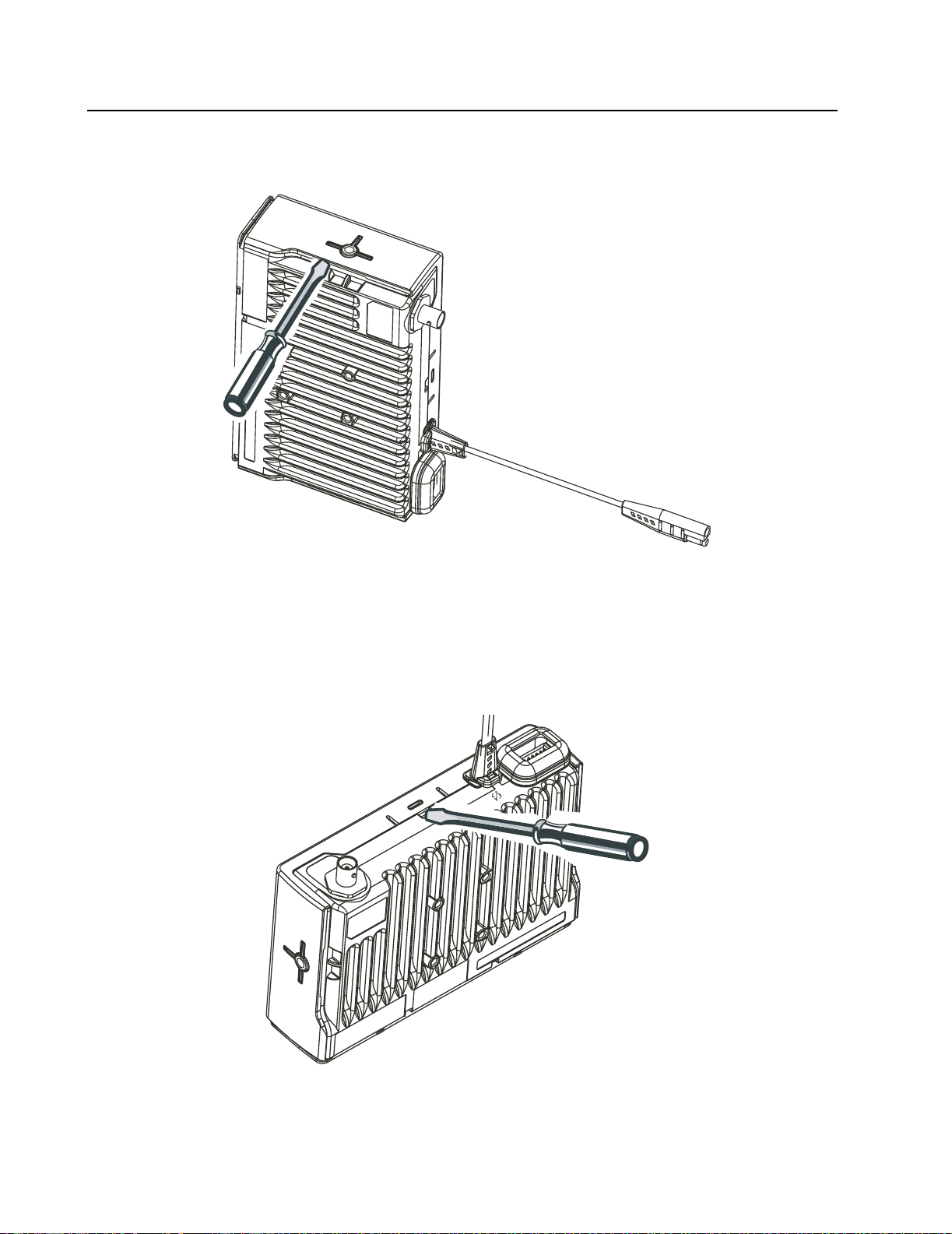
6.2 Top Cover Removal
1. Place the radio in a vertical position as shown in Figure 2-4.
Figure 2-4 Top Cover Removal (Chassis Vertical).
2. Insert the flat screw driver near the ‘T’ and push the plastic cover up until it pops over the ‘T’
mount boss. Perform the same function on the ‘T’ location on the other side of the chassis.
3. Next place the radio in a horizontal position as shown in Figure 2-5 and insert the flat screw
driver into the slot to release the upper cover.
Figure 2-5 Top Cover Removal (Chassis Horizontal)
Page 21
Radio Disassembly - Detailed 2-7
6.3 Main Shield Removal
1. Insert the screw driver in the gap between the main shield and chassis (speaker cutout area)
and push the shield up. See Figure 2-6.
2. Lift the cover from the chassis.
Figure 2-6 Main Shield Removal
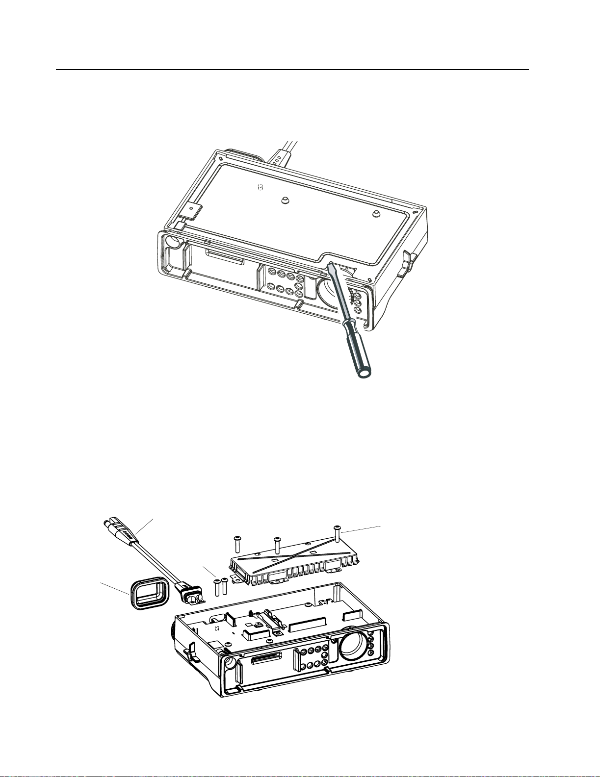
6.4 PA Shield and DC Cable Removal
1. Remove the three screws that attach the PA shield to PCB, and remove the PA shield.
2. Remove the accessory Connector cap.
3. Remove the two screws that attach the DC power cable to the PCB and pull it out from the
side.
DC
Cable
DC Cable
Accessory
Connector
Cap
Fixing Screws
(2)
PA Shield
Fixing Screws (3)
Figure 2-7 PA Shield and DC Cable Removal (for Low Power Models)
Page 22

2-8 MAINTENANCE
Figure 2-8 PA Shield and DC Cable Removal (for High Power Models)
6.5 PA Clip and Main PCB Removal (for Low Power Models)
1. Remove the screw that attaches the PA clip to the chassis. See Figure 2-9.
2. Remove the PA clip.
3. Remove all the screws that fix the PCB to the chassis.
4. Loosen the M2 screw (about 3 to 4 turns) on the RF connector using hex tool
(Part number: 6680334F39).
5. Loosening this screw, enables you to unscrew the RF connector from outside.
6. Carefully remove the main PCB in a diagonal manner.
NOTE
It is recommended to grip the volume potentiometer and remove the PCB board
Main PCB
PA Clip
M2 Screw
Figure 2-9 PA Clip and Main PCB Removal (for Low Power Models)
Page 23

Radio Disassembly - Detailed 2-9
6.6 Main PCB Removal (for High Power Models)
1. Remove the PA screws. See Figure 2-10.
2. Remove all the screws that fix the PCB to the chassis.
3. Loosen the M2 screw (about 3 to 4 turns) on the RF connector using hex tool
(Part number: 6680334F39).
4. Loosening this screw, enables you to unscrew the RF connector from outside.
5. Carefully remove the main PCB in a diagonal manner.
NOTE
It is recommended to grip the volume potentiometer and remove the PCB board
Figure 2-10 PA Clip and Main PCB Removal (for High Power Models)
Page 24

2-10 MAINTENANCE
6.7 Disassembly of Control Head - CM200
1. Disconnect the flat cable from the Control Head PCB connector. See Figure 2-11.
2. Remove the PCB from the keypad assembly.
3. Remove the LENs from the rubber keypad assembly.
4. Remove the keypad assembly from the control head housing by lifting it up from the face
side.
5. Disconnect the speaker socket and remove the speaker from the keypad assembly.
NOTE
.
DO NOT touch or contaminate the conductive pads on the under side of the keypad
or the conductive contacts on the printed circuit board.
Control Head Housing
Keypad Assembly
Lens
PCB
Speaker
Figure 2-11 Control Head Housing Removal CM200
Page 25

Radio Disassembly - Detailed 2-11
6.8 Disassembly of Control Heads - CM300/PM400
1. Disconnect the flat cable from the Control Head PCB connector. See Figure 2-12.
2. Remove the PCB from the keypad assembly.
3. Remove the LCD assembly from the rubber keypad assembly.
4. Remove the keypad assembly from the control head housing by lifting it up from the face side.
5. Disconnect the speaker socket and remove the speaker from the keypad assembly.
NOTE
DO NOT touch or contaminate the conductive pads on the under side of the keypad,
the conductive contacts on the printed circuit board or the elastomeric connector.
Control Head Housing
Speaker
Figure 2-12 Control Head Housing Removal CM300/PM400
Keypad Assembly
LCD Assembly
PCB
Page 26

2-12 MAINTENANCE
7.0 Radio Assembly
7.1 Chassis Assembly (for Low Power Models)
1. Ensure that the Fuji Poly Thermal Pad is on the small pedestal located on the PA
compartment of the chassis.
2. Verify that the potentiometer is soldered properly.
3. Take the main PCB and smear thermal paste on LDMOS Power Amplifier, TO220, and Audio
Power Amplifier.
4. Slide the main board diagonally into the chassis.
5. Tighten all eight screws (Torx T10).
6. Assemble the O-ring on the RF connector and tighten it using Torque 22 lb.in.
7. Tighten the RF connector security screw M2 using Torque 1.5 lb. (through the opening in the
PCB).
8. Take the Power Amplifier Clip and insert the leg-shape side into the opening groove located
on the PCB. Tighten the screw using Torque 13 lb.in
9. Take the PA Shield and place it on the PA compartment. Tighten the three screws using
Torque 13 lb.in. Tighten the middle screw first, then the screw located on the left side, and
lastly the screw located on the right side.
10. Insert the DC cable into the slot. Ensure that it is seated correctly on the chassis hook located
below the DC cable. Attach it to the chassis and PCB by tightening the two screws using
Torque 13 lb.in (Torx T10).
11. Take the main shield and place it on the chassis. Check that the corners of the main shield
are seated properly on the corner supports.
12. Take the main seal and place it inside the top cover. Verify that the main seal is seated properly on its placement ribs and all around the groove.
13. Take the upper cover, place it properly on the chassis, and push it down. Three click sounds
are heard from both sides and back.
7.2 Chassis Assembly (for High Power Models)
1. Verify that the potentiometer is soldered properly.
2. Take the main PCB and smear thermal paste on T0220 and Audio Power Amplifier.
3. Slide the main board diagonally into the chassis.
4. Tighten all eight screws (Torx T10).
5. Assemble the O-ring on the RF connector and tighten it using Torque 22 lb.in.
6. Tighten the RF connector security screw M2 using Torque 1.5 lb. (through the opening in the
PCB).
7. Take two PA Screws and place in screw holes over PA. Tighten the screws using Torque 13
lb.in.
8. Take the PA Shield and place it on the PA compartment. Tighten the three screws using
Torque 13 lb.in. Tighten the middle screw first, then the screw located on the left side, and
lastly the screw located on the right side.
9. Insert the DC cable into the slot. Ensure that it is seated correctly on the chassis hook located
below the DC cable. Attach it to the chassis and PCB by tightening the two screws using
Torque 13 lb.in. (Torx T10).
Page 27

Radio Assembly 2-13
10. Take the main shield and place it on the chassis. Check that the corners of the main shield are
seated properly on the corner supports.
11. Take the main seal and place it inside the top cover. Verify that the main seal is seated properly on its placement ribs and all around the groove.
12. Take the upper cover, place it properly on the chassis, and push it down. Three click sounds
are heard from both sides and back.
7.3 Control Heads Assembly
1. Assemble the Control Heads by reversing the procedure for dis-assembly..
NOTE
Care should be taken not to touch or contaminate the conductive strip connectors and keypad conductors on the underside of the display and the elastomeric connectors (GM3689
only).
7.4 Control Head Fitting
1. Hold the Control Head in one hand and the chassis assembly in the other hand.
2. Insert the flat cable into the main PCB connector through the slot in the chassis.
3. Place the Control Head Assembly on the chassis assembly in a diagonal manner. Two clicking
sounds are heard.
4. Insert the Volume Knob into its groove and push it in.
5. Place the cap of the accessory connector over the accessory pin.
Page 28

2-14 MAINTENANCE
7.5 Option Board Installation
1. Follow the disassembly procedure in paragraphs 6.1 to 6.3.
2. Remove and discard the 4xM3 screws holding the main pcb and replace with the 4 spacers
provided. Torque the spacers to 10 lbs.
3. Insert the jumper flex into the connector on the option board. Notice the orientation of the
right-angle flex circuit.
4. Insert the other end of the jumper flex into the connector on the main pcb.
5. Fold the flex circuit under the option board.
6. Position the option board over the spacers and retain using the 4xM2 screws provided.
M2 Screws
Option Board
Flex
Spacers
4xM3 screws
(replaced by spacers)
Figure 2-13 Option Board Installation
7. With the option board correctly in place, the main shield and top cover can be assembled as
detailed in paragraph 7.1 steps 11 to 13.
Page 29

Radio Exploded Mechanical Views and Parts Lists 2-15
8.0 Radio Exploded Mechanical Views and Parts Lists
8.1 Radio Assembly - 1-25 W Models
Figure 2-14 Radio Assembly - 1-25 W Models
Table 2-1 Radio Assembly Parts List - 1-25 W Models
Item No. Description Part Number
1 Upper Cover 1589224U01
2 Main Seal 3289329U01
3 Bumper 7587509V06
4 Main Shield 2689338U01
5 PA Shield 2689337U01
6 Screw 0310943J12
7 PA Clip 0789352U01
8 VHF Main PCB
UHF Main PCB
9 Connector Jack:
Mini UHF
BNC
10 O-Ring 5802810C15
11 Power Cable Assembly 0189484U01
12 Cap, Accessory Connector 3202607Y01
13 Chassis 25W 2789223U01
14 Felt 3586661Z01
See Chapter 7 Model
Charts and
Specifications.
5802810C15
5802810C16
Page 30

2-16 MAINTENANCE
8.2 Radio Assembly - 25-40 W/25-45 W Models
Figure 2-15 Radio Assembly - 25-40 W/25-45 W Models
Table 2-2 Radio Assembly Parts List - 25-40 W/25-45 W Models
Item No. Description Part Number
1 Upper Cover 1589224U01
2 Main Seal 3289329U01
3 Main Shield 2689338U01
4 PA Shield 2689337U01
5 Screw 0310943J12
6 VHF Main PCB (45W)
UHF Main PCB (40W)
7 Connector Jack:
Mini UHF
BNC
8 O-Ring 5802810C15
9 Power Cable Assembly 0189484U01
10 Cap, Accessory Connector 3202607Y01
11 Chassis 40W 2789223U02
12 Felt 3586661Z01
13 PA S c r e w 0386663Z01
14 Bumper 7587509V06
See Chapter 7 Model
Charts and
Specifications.
5802810C15
5802810C16
Page 31

Radio Exploded Mechanical Views and Parts Lists 2-17
8.3 Control Head - CM200
1
2
3
4
5
Figure 2-16 Control Head CM200
Table 2-3 Control Head CM200 Parts List
7
9
6
Item no Description Part No
1 Control Head PCB 8488998U01
2 Lens 6189338U01
3 Keypad 7589330U01
4 Control Head Plastic 1589332U01
5 Knob Spring (part of knob - item 6)
6 Knob, Volume 3689331U02
7 Speaker 5005156Z02
8 Flat Cable (not shown) 3089305U01
9 Nameplate 5487790V03
Page 32

2-18 MAINTENANCE
8.4 Control Head - CM300/PM400
1
4
5
7
2
3
6
8
9
Figure 2-17 Control Head - CM300/PM400
Table 2-4 Control Head CM300/PM400 Parts List
Item no Description Part No.
1 Control Head PCB 8489714U01
2 Light Guide 6189624U01
3 Elastomeric Connector 2802619S03
4 LCD Holder 0789623U01
5 LCD 7202421H33
6 Keypad 7589340U01
7 Speaker 5005156Z02
8 Control Head Plastic
CM300
PM400
9 Knob Spring (part of Knob - item 10)
10 Knob 3689331U02
11 Lens:
CM300
PM400
12 Flat Cable (Not Shown) 3089305U01
1586605Z01
1589333U01
6189339U07
6189339U04
11
10
Page 33

Service Aids 2-19
9.0 Service Aids
Table 2-5 lists the service aids recommended for working on the radio. While all of these items are
available from Motorola, most are standard workshop equipment items, and any equivalent item
capable of the same performance may be substituted for the item listed.
Table 2-5 Service Aids
Motorola Part
No.
RLN4460_ Portable Test Set Enables connection to audio/accessory jack.
HVN4191_ Customer Programming
Software (CPS) - Software on
CDROM & Global Tuner
RKN4081_ Programming Cable with
Internal RIB
FKN8096_ Data/Flash Adapter Key Used with RKN4081 (10 to 8 pin adapter for
RKN4083_ Mobile Programming/Test Cable Connects radio to RIB (RLN4008_).via rear
FKN8113_ Adapter Cable Used with RKN4083 (20 to 16 pin adapter for
GTF 37 4 _ Program Cable Connects RIB to Radio microphone input.
RLN4008_ Radio Interface Box Enables communications between radio and
Description Application
Allows switching for radio testing.
Programs customer options and channel data.
Includes radio interface box (RIB) capability.
front Telco connector with Data/Flash switch).
accessory connector
rear accessory connector).
computer’s serial communications adapter.
HSN9412_ Wall-Mounted Power Suppy Used to power the RIB. (120 V ac)
HLN8027_ Mini UHF to BNC Adaptor Adapts radio antenna port to BNC cabling of
test equipment.
8180384N64 Housing Eliminator (25W) Test Fixture used to bench test the radio pcb.
3080369B71 Computer Interface Cable Connects the RIB to the Computer (25-pin).
3080369B72 Computer Interface Cable Connects the RIB to the Computer (9-pin)
(Use for IBM PC AT - other IBM models use
the B71 cable above).
6686119B01 Removal Tool Assists in the removal of radio control head.
6680334F39 Hex Tool Assists in the removal of antenna connector.
Page 34

2-20 MAINTENANCE
10.0 Test Equipment
Table 2-6 lists test equipment required to service the radio and other two-way radios
.
Table 2-6 Recommended Test Equipment
Motorola Part No. Description Characteristics Application
R2000, R2600
R2400, or R2001
with trunking
option for Privacy Plus™ and
Smartnet Systems™
*R1049 Digital Multimeter Two meters recommended for AC/
*S1100 Audio Oscillator 67 to 200Hz tones Used with service monitor for injec-
*S1053,
*S K N6009,
*SKN6001
R1053 Dual-trace Oscillo-
R1443A Broadband Watt-
†
Service Monitor This monitor will
substitute for items
listed below with an
asterisk *
AC Voltmeter,
Power Cable
for meter,
Test leads for meter
scope
meter
• 1 mV to 300 V
• 10 MΩ input impedance
20 MHz bandwidth,
5 mV/cm - 20 V/cm
Frequency/deviation meter and signal generator for wide-range troubleshooting and alignment
DC voltage and current measurements
tion of PL tones
Audio voltage measurements
Waveform measurements
Transmitter power output measurements
S1339 RF Millivolt Meter 100 µV to 3 VRF, 10
kHz to 1.2 GHz
*R1013 SINAD Meter Receiver sensitivity measurements
S1348 (prog) DC Power Supply 0-20 Vdc, 0-20 Amps Bench supply for 13.8Vdc
RF level measurements
Page 35

Programming/Test Cable - RKN4083_ 2-21
11.0 Programming/Test Cable - RKN4083_
FLO830308-0
J1 (Female)
To RIB
RLN4008
13
25
+
_
1
14
1
14
+
_
1000 50mm
Cable
1
19
20
2
P1 (Male)
To Radio
Test Set
13
25
1000 50mm
To Mobile Radio
17
18
Cable
J2 (Female)
Accessory
Connector
Viewed from
Front (pin end)
of Connector
Note: Use with Adapter Cable FKN8113_
FL0830308O
Figure 2-18 Programming/Test Cable
SPEAKER -
EXTERNAL MIC
DIGITAL IN 1 (EXT. PTT)
DIGITAL OUT 2 (EXT. ALARM)
FLAT TX AUDIO SENSITIVITY
DIGITAL IN 3/MPT MAP 27 RX
DIGITAL IN/OUT 4/MPT MAP 27 TX
DIGITAL IN 5 w WAKEUP (EMG)
FLAT/FILTERED RX AUDIO
SWITCHED BATTERY VOLTAGE
BUS + (FOR CPS AND FLASHING)
FL0830307O
IGNITION
DIGITAL IN/OUT 7
DIGITAL IN/OUT 8
SPEAKER +
BOOT CONTROL
GND
RSSI
N/C
N/C
J2 Mobile
Radio
Accessory
Connector
1
2
3
4
5
6
7
8
9
10
11
12
13
14
15
16
17
18
19
20
P1
To Radio
Test Set
RLN4460
10
15
16
18
19
20
25
J1
To RIB
RLN4008
11
12
15
25
AUDIO +
1
AUDIO -
2
AUDIO +
5
AUDIO -
7
MIC AUDIO
MIC AUDIO
GND
VOL CTRL
DISC
PTT
BOOT CTRL
1
GND
4
BIAS
BUS SW B +
BUS +
BOOT CTRL
Figure 2-19 Pin Configuration of RKN4083
FLO830307-0
Page 36

2-22 MAINTENANCE
12.0 Adapter Cable - FKN8113_
SPEAKER -
EXTERNAL MIC
EXT. PTT
FLAT TX AUDIO SENSITIVITY
BUS+ (FOR CPS AND FLASHING)
GND
SWITCHED BATTERY VOLTAGE
SPEAKER +
1
2
16-pin Female
To Radio
Accessory
Connector
1
2
3
4
5
6
7
8
9
10
11
12
13
14
15
16
15
16
20-pin Male
To Prog/Test
Cable
RKN4083_
SPEAKER -
1
EXTERNAL MIC
2
EXT.PTT
3
EXT ALARM
4
FLA T TX AUDIO
5
DIG IN
6
GND
7
DIG I/O
8
DIG IN
9
IGNITION
10
FLAT/FILTERED RX AUDIO
11
DIG IN
12
SWITCHED BATTERY VOLTAGE
13
DIG IN
14
RSSI
15
SPEAKER +
16
BUS +
17
BOOT CONTROL
18
N/C
19
N/C
20
Viewed from
Front (pin end)
of Connector
Figure 2-20 Pin Configuration of FKN8113
Page 37

1.0 General
These radios meet published specifications through their manufacturing process by utilizing highaccuracy laboratory-quality test equipment. The recommended field service equipment approaches
the accuracy of the manufacturing equipment with few exceptions. This accuracy must be
maintained in compliance with the manufacturer’s recommended calibration schedule.
2.0 Setup
Supply voltage is provided using a power supply (13.8 Vdc for low power models, 13.6 Vdc for high
power models). The equipment required for alignment procedures is connected as shown in the
Radio Tuning Test Setup Diagram, Chapter 4, Figure 4-6.
Initial equipment control settings should be as indicated in Table 3-1. The remaining tables in this
chapter contain the following related technical data:
Chapter 3
TRANSCEIVER PERFORMANCE TESTING
Table Number Title
3-2 Test Environments
3-3 Test Channel Spacing
3-4 Test Frequencies
3-5 Transmitter Performance Checks
3-6 Receiver Performance Checks
Table 3-1 Initial Equipment Control Settings
Service Monitor Test Set Power Supply
Monitor Mode: Power Monitor Spkr set: A Voltage: 13.8 Vdc (low
power models) 13.6 Vdc
(high power models)
RF Attn: -70 Spkr/load:
Speaker
AM, CW, FM: FM PTT: OFF Volt Range: 20V
Oscilloscope Source: Mod
Oscilloscope Horiz: 10mSec/Div
Oscilloscope Vert: 2.5 kHz/Div
Oscilloscope Trig: Auto
Monitor Image: Hi
Monitor BW: Nar
Monitor Squelch: mid CW
Monitor Vol: 1/4 CW
DC On/Standby:
Standby
Current: 20A
Page 38

3-2 TRANSCEIVER PERFORMANCE TESTING
3.0 RF Test Mode
When the radio is operating in its normal environment, it is not possible to test all individual aspects
of the transmitter and receiver performance. Therefore a special “test mode” is used to allow the
service technician to perform certain functional tests on the product. A control head fuctional test
mode is also available.
To enter test mode (display radios):
1. Turn the radio on.
2. Within ten seconds after the self test is complete, press button P2, five times in succession.
3. Channel number appears in the display. The radio is on channel XX*, carrier squelch mode,
25 kHz channel spacing.
4. Each additional press of P2 scrolls through to the next channel spacing and a corresponding
set of tones are sounded.
5. Pressing P1 scrolls through and accesses test environments as shown in Table 3-2.
6. Pressing P2 for three seconds switches the radio to the control head test mode and zero
appears on the display.
7. Pressing P1 causes the radio to display the channel number “1”. Another P1 press causes
the radio to display the next channel “2”, and so on until channel “9”.
8. Pressing P1 at the end of the LCD test activates the ‘LED Test’. The next P1 press turns the
LEDs and dot On/Off.
9. Pressing P1 at the end of the LED test activates the button test. Pressing any button (except
P1) or any keypad button during the LCD test or Icon test immediately activates this test.
10. Pressing P2 for 3 seconds in the control head test mode causes the radio to return to the RF
test mode.
*XX = channel number (01 - 06)
Table 3-2 Test Environments
No. of
Beeps
1 Carrier Squelch RX: if carrier detected
1Tone
2 Digital
3Dual-Tone
9 MDC1200
5 Unsquelch
11 CMP RX: if carrier detected
Description Function
TX: mic audio
RX: unsquelch if carrier and tone (192.8H z) detected
Private-Line
RX: unsquelch if carrier and digital code (131) detected
Private-Line
multiple
frequency
HSS
Open
TX: mic audio + tone (192.8 Hz)
TX: mic audio + digital code (131)
RX: unsquelch if carrier detected
TX: selected DTMF tone pair
RX: unsquelch if carrier detected
TX: 1500 Hz tone
RX: constant unsquelch
TX: mic audio
TX: mic audio
Page 39

RF Test Mode 3-3
Table 3-3 Test Channel Spacing
Number of Beeps Channel Spacing
1 25 kHz
2 12.5 kHz
3 20 kHz
Table 3-4 Test Frequencies
Channel Display Test Channel
1 Low Power
8 High Power
2 Low Power
9 High Power
3 Low Power
10* High Power
4 Low Power
11* High Power
5 Low Power
12* High Power
6 Low Power
13* High Power
7 Low Power
14* High Power
TX#1 or #8
RX#1 or #8
TX#2 or #9
RX#2 or #9
TX#3 or #10
RX#3 or #10
TX#4 or #11
RX#4 or #11
TX#5 or #12
RX#5 or #12
TX#6 or #13
RX#6 or #13
TX#7 or #14
RX#7 or #14
VHF
(136-162
MHz)
136.125 146.025 438.025 465.225
140.275 150.700 443.300 470.225
144.675 155.300 448.700 475.225
149.125 160.000 454.000 480.225
153.475 164.700 459.300 485.225
157.775 169.300 464.700 490.225
161.775 173.025 469.025 494.775
VHF
(146-174
MHz)
UHF
(438-470
MHz)
* The CM200 displays only the 2nd digit and the high power indicator is illuminated.
UHF
(465-495
MHz)
Table 3-5 Transmitter Performance Checks
Test Name Communications Analyzer Radio Test Set Comment
Reference
Frequency
Mode: PWR MON
4th channel test frequency*
Monitor: Frequency error
Input at RF In/Out
TEST MODE,
Test Channel 4
carrier squelch
PTT to
continuous
(during the
performance
check)
Frequency error to
be: ±186 Hz VHF1
±200 Hz VHF2
±568 Hz UHF2
±600 Hz UHF3
Power RF As above As above As above 1-25 W
Page 40

3-4 TRANSCEIVER PERFORMANCE TESTING
Table 3-5 Transmitter Performance Checks (Continued)
Test Name Communications Analyzer Radio Test Set Comment
Voice
Modulation
Voice
Modulation
(internal)
High-Speed
Data
Modulation
Mode: PWR MON
As above As above,
4th channel test frequency*
atten to -70, input to RF In/ Out
Monitor: DVM, AC Volts
Set 1kHz Mod Out level for
800mVrms at test set,
800mVrms at AC/DC test set
jack
Mode: PWR MON
4th channel test frequency*
atten to -70, input to RF In/ Out
TEST MODE,
Test Channel 4
carrier squelch
output at
antenna
As above TEST MODE,
Test Channel 4
high speed
output at
antenna
meter selector
to mic
Remove
modulation
input
PTT to
continuous
(during the
performance
check).
Deviation:
2.5 kHz Max.
(12.5 kHz Ch. Sp).
4 kHz Max.
(20 kHz Ch. Sp).
5 kHz Max.
(25 kHz Ch. Sp).
Deviation:
2.5 kHz Max.
(12.5 kHz Ch. Sp.).
4 kHz Max.
(20 kHz Ch. Sp.).
5 kHz Max.
(25 kHz Ch. Sp.).
Deviation:
1.5-2.0 kHz
(12.5 kHz Ch. Sp.).
2.3-3.2 kHz
(20 kHz Ch. Sp.).
3.0-4.0 kHz
(25 kHz Ch. Sp.).
DTMF
Modulation
PL/DPL
Modulation
* See Table 3-4.
As above,
4th channel test frequency*
As above
4th channel test frequency*
BW to narrow
TEST MODE,
Test Channel 4
DTMF output at
antenna
TEST MODE,
Test Channel 4
TPL
DPL
As above Deviation:
1.4-1.9 kHz
(12.5 kHz Ch. Sp.).
2.3-3.0 kHz
(20 kHz Ch. Sp.).
2.9-3.8 kHz
(25 kHz Ch. Sp.).
As above Deviation:
0.25-0.5 kHz
(12.5 kHz Ch. Sp.).
0.4-0.8 kHz
(20 kHz Ch. Sp.)
0.5-1.0 kHz
(25 kHz Ch. Sp.).
Page 41

RF Test Mode 3-5
Table 3-6 Receiver Performance Checks
Test Name Communications Analyzer Radio Test Set Comment
Reference
Frequency
Rated Audio Mode: GEN
Mode: PWR MON
4th channel test frequency*
Monitor: Frequency error
Input at RF In/Out
Output level: 1.0mV RF
4th channel test frequency*
Mod: 1kHz tone at
TEST MODE,
Test Channel 4
carrier squelch
output at
antenna
TEST MODE
Test Channel 4
carrier squelch
PTT to
continuous
(during the
performance
check)
PTT to OFF
(center),
meter selector
to Audio PA
Frequency error to
be: ±186 Hz VHF1
±200 Hz VHF2
±568 Hz UHF2
±600 Hz UHF3
Set volume control
to 8.10Vrms
3kHz deviation
Monitor: DVM: AC Volts
Distortion As above, except to distortion As above As above Distortion <5.0%
Sensitivity
(SINAD)
As above, except SINAD,
lower the RF level for 12dB
As above PTT to OFF
(center)
RF input to be
<0.3µV
SINAD.
Noise
Squelch
Threshold
(only radios
with
conventiona
l system
RF level set to 1mV RF As above PTT to OFF
(center),
meter
selection to
Audio PA,
spkr/ load to
speaker
Set volume control
to 3.16Vrms
need to be
tested)
As above, except change
frequency to a conventional
system. Raise RF level from
zero until radio unsquelches.
* See Tables 3-4.
out of TEST
MODE; select a
conventional
system
As above Unsquelch to occur
at <0.25µV.
Preferred SINAD =
9-10dB
Page 42

3-6 TRANSCEIVER PERFORMANCE TESTING
THIS PAGE INTENTIONALLY LEFT BLANK
Page 43

1.0 Introduction
This chapter provides an overview of the Customer Programming Software (CPS) and tuner
program designed for use in a Windows 98/ME/NT/2000 environment.
Chapter 4
RADIO TUNING AND PROGRAMMING
NOTE
Refer to the CPS on-line help files for programming procedures.
Table 4-1 Software Installation Kits Radio Tuning Setup
Description Kit Number
CPS RVN4191_
2.0 CPS Programming/Flashing Setup with RIB
The CPS programming setup, shown in Figure 4-1 is used to program and flash the radio using the
Radio front Telco connector.
ACC
FKN8096
Data =Programming
Boot = Flashing
8-pin Telco
FKN8096
10-pin Telco
Radio
DC
RF
Power
Supply
Programming
Cable
3080070N01
DB25
RIB
RLN-4008
DB15
Cable 3080369B72 (9 PIN)
Cable 3080369B71 (25 PIN)
Tx Data
Rx
Data
Gnd
Figure 4-1 CPS Programming/Flashing Setup with RIB
Page 44

4-2 RADIO TUNING AND PROGRAMMING
3.0 CPS Programming/Flashing Setup Ribless
The CPS programming setup, shown in Figure 4-2 is used to program and flash the radio using the
Radio front Telco connector.
ACC
FKN8096
Data =Programming
Boot = Flashing
8-pin Telco
FKN8096
10-pin Telco
Radio
DC
RF
Power
Supply
DB25
Tx Data
Rx Data
Gnd
Ribless Programming Cable RKN4081
Figure 4-2 CPS Programming/Flashing Setup Cable with Internal RIB
4.0 CPS Programming Setup with RIB (with Telco Connector)
The CPS programming setup, shown in Figure 4-3 is used to program the radio using the Radio front
Telco connector.
ACC
Programming
Cable
GTF374
Radio
DB25
DC
RF
RLN-4008
Power
Supply
DB15
RIB
Cable 3080369B72 (9 PIN)
Cable 3080369B71 (25 PIN)
Tx Data
Rx
Data
Gnd
Figure 4-3 CPS Programming Setup with RIB
Page 45

CPS Programming Setup with RIB (Accessory Connector) 4-3
5.0 CPS Programming Setup with RIB (Accessory Connector)
The CPS programming setup, shown in Figure 4-4 is used to program the radio using the Radio rear
accessory connector.
Adapter Cable
FKN8113
Power
Supply
Programming/Test
Cable
RKN4083
Figure 4-4 CPS Programming Setup Cable with RIB and Rear Adapter Cable
ACC
DC
RF
DB25
Radio
RIB
RLN-4008
DB15
Cable 3080369B72 (9 PIN)
Cable 3080369B71 (25 PIN)
Tx Data
Rx
Data
Gnd
6.0 CPS Programming Setup with RIB
The CPS programming setup, shown in Figure 4-5 is used to program the radio using the Radio rear
accessory connector.
Cable
GTF377
Power
Supply
Programming
Cable
GTF374
Figure 4-5 CPS Programming Setup Cable with RIB and Rear Adapter Cable
ACC
DC
RF
DB25
Radio
RIB
RLN-4008
DB15
Cable 3080369B72 (9 PIN)
Cable 3080369B71 (25 PIN)
Tx Data
Rx
Data
Gnd
Page 46

4-4 RADIO TUNING AND PROGRAMMING
7.0 Radio Tuning Setup
A personal computer (PC), Windows 95/98/NT and a tuner program are required to tune the radio.
To perform the tuning procedures, the radio must be connected to the PC, radio interface box (RIB),
and test equipment setup as shown in Figure 4-6.
Tes t B ox
RLN4460
ELM Adapter
cable FKN8113
ACC
DC
Radio
RF
Program/
RKN4083
Power
Supply
30 dB Pad
Tes t Ca b le
RLN-4008
RIB
Cable 3080369B72 (9 PIN)
Cable 3080369B71 (25 PIN)
Figure 4-6 Radio Tuning Test Equipment Setup with External RIB
7.1 Initial Test Equipment Control Settings
The initial test equipment control settings are listed in Table 4-2.
DB15
Audio In
Transmit
Receive
Tx
Audio Generator
Rx
Sinad Meter
AC Voltmeter
Tx Data
Rx Data
Gnd
RF Generator
Service Monitor
or Counter
Wattmeter
Table 4-2 Initial Equipment Control Settings
Service Monitor Test Set Power Supply
Monitor Mode: Power Monitor Speaker set: A Voltage: 13.8 Vdc (low
power models)
13.6 Vdc (high power
models)
RF Attenuation: -70 Speaker/load:
Speaker
AM, CW, FM: FM PTT: OFF Volt Range: 20 V
Oscilloscope Source: Mod
Oscilloscope Horizontal: 10mSec/Div
Oscilloscope Vertical: 2.5 kHz/Div
Oscilloscope Trigger: Auto
Monitor Image: Hi
Monitor BW: Nar
Monitor Squelch: mid CW
Monitor Volume: 1/4 CW
NOTE
Refer to Tuner on-line help files for tuning procedures.
DC on/standby:
Standby
Current: 20A
Page 47

1.0 Error Codes
Turning on the radio starts a self-test routine that checks the RAM, ROM checksum, EEPROM
hardware, and EEPROM checksum. If these checks are successful, the radio generates two high-
pitched self-test pass tones. If the self-test is not successful, one low-pitched tone is heard. Radios
with displays are able to display the error codes. Following are the possible errors and the related
connections.
Possible Errors To correct the problem...
RAM test failure. Retest the radio by turning it off and turning it on
Chapter 5
POWER UP SELF-TEST
Table 5-1 Power Up Error Codes
again. If bad tone reoccurs, replace RAM (U0122).
Codeplug structure mismatch or non existence of
codeplug.
Wrong codeplug checksum. Reprogram codeplug.
Reprogram codeplug with correct version and retest
radio. If message reoccurs, replace EEPROM
(U0111).
Page 48

5-2 POWER UP SELF-TEST
THIS PAGE INTENTIONALLY LEFT BLANK
Page 49

ACCESSORIES & CONNECTOR PIN FUNCTIONS
1.0 Accessories
To order, refer to Chapter 1 (paragraph 3.0 - ‘Replacement Parts Ordering’) of this manual.
1.1 Antennas
VHF
HAD4006_ 136 - 144 MHz, 1/4 Wave Roof Mount
HAD4007_ 144 - 150.8 MHz, 1/4 Wave Roof Mount
HAD4008_ 150.8 - 162 MHz, 1/4 Wave Roof Mount
HAD4009_ 162 - 174 MHz, 1/4 Wave Roof Mount
RAD4000_ 136 - 174 MHz, 3 dB Gain (No Mount)
HAD4014_ 140 - 174 MHz, 3.5 dB Gain Roof Mount
UHF
Chapter 6
HAE4002_ 403 - 430 MHz, 1/4 Wave Roof Mount
HAE4003_ 450 - 470 MHz, 1/4 Wave Roof Mount
HAE4004 470 - 512 MHz, 1/4 Wave Roof Mount
HAE4010_ 406 - 420 MHz, 3.5 dB Gain Roof Mount
HAE4011_ 450 - 470 MHz, 3.5 dB Gain Roof Mount
RAE4004_RB 445 - 470 MHz, 5 dB Gain Roof Mount
RAE4004_MB 445 - 470 MHz, 5 dB Gain Magnetic Mounts
TAE6053_ 430 - 450 MHz, 1/4 Wave Roof Mount
Page 50

6-2 ACCESSORIES & CONNECTOR PIN FUNCTIONS
1.2 Audio
HMN3596_ Compact Palm Microphone (Std. Mic)
HMN1035_ Heavy Duty Microphone
RMN5029_ Enhanced Keypad Microphone
RMN5018_ Mag One Microphone (Low Cost) (6 months warranty only)
RMN5019_ Mag One Keypad Microphone (Low Cost) (6 months warranty only)
AAREX4617_ Telephone Style Handset Kit
GMMN4065_ Visor Microphone (Omni Direction)
AARMN4027_ Visor Microphone - High Noise (Uni-Direction)
RSN4001_ External Speaker, 13 W
HSN8145_ External Speaker, 7.5 W
HLN9073_ Microphone Hang-up Clip (requires install)
HLN9414_ Microphone Hang-up Clip (Universal - no install required)
1.3 Alarms and Accessories
RLN4856_ Footswitch with Remote PTT
RLN4857_ Pushbutton with Remote PTT
RLN4858_ Gooseneck PTT
RLN4836_ External PTT with Emergency Footswitch
HLN9328_ External Alarm Relay (used in conjunction with GLN7282)
GLN7282_ Buzzer Kit (used in conjunction with HLN9328)
Page 51

Accessories 6-3
1.4 Control Station
HPN4002_ Desktop Power Supply 1-25 W
HPN4001_ Desktop Power Supply 25-60 W
HMN3000_ Black Desk Microphone
RLN5390_ Desktop Tray with Speaker
RLN5391_ Desktop Tray without Speaker
RLN5492 Low Power Control Station Kit (1-25 W) (includes power supply,
desktop tray, and desk mic)
RLN5493 High Power Control Station Kit (25-60 W) (includes power supply,
desktop tray, and desk mic)
1.5 Public Address
RLN5288_ Public Address Kit (includes switch box and cabling)
HKN9324_R Speaker Cable for PA (15 ft.)
HSN1000_R External Speaker, 6 W for public address
1.6 Cables
HKN9327_R Ignition Switch Cable
HKN4137_ Low Power Cable to Battery (1-25 W)
HKN4191_ High Power Cable to Battery (25-60 W)
1.7 Mounting
GLN7324_ Low Profile Mounting Bracket
GLN7317_ High Profile Mounting Bracket
FTN6083_ DIN Mount
HLN8097_ Removable Slide Mount with Mini_U connector
HLN9227_ 8 in. Gooseneck Trunnion
RLN4779_ Keylock Mounting Bracket
Page 52

6-4 ACCESSORIES & CONNECTOR PIN FUNCTIONS
1.8 Data - CES Wireless Technologies
RDN7364_ Base Modem
RDN7367_ Mobile Display Terminal with GPS
RDN7368_ Mobile Display Terminal
RDN7369_ Stand Alone Modem with GPS
RDN7370_ Interface Cable, 3 ft
RDN7376_ Interface Cable, 15 ft
RDN7372_ Fixed Mount GPS Active Antenna
RDN7373_ Mobile Printer
RDN7374_ Programming Software for CES Equipment
RDN7380_ Mobile Programming Hardware
RDN7375_ Magnetic Mount GPS Antenna
RDN7377_ MAPS (US) Regional
RDN7378_ AVL Messaging Statue Software
RDN7371_ Credit Card Reader
RDN7738_ Serial Breakout Unit (multiple modems)
RDN7739_ Flying Lead Cable, 3 ft.
RDN7740_ Flying Lead Cable, 15 ft.
1.9 Peripherals
HLN3948 Basic RICK (Repeater Interface Comm Kit)
HLN3333 RICK (Repeater Interface Comm Kit)
Page 53

Accessory Connector Pin Function 6-5
2.0 Accessory Connector Pin Function
Pin Function Description
1 External Speaker (-) Connect external 8 or 4 ohms speaker to pin 1 and 16.
Caution: Bridge-type output. Neither pin 1 or 16 is grounded.
2 External Mic Audio Input impedence:500 ohms
80 mV rms at 1 kHz for 60% deviation.
This path is enabled when external mic PTT is keyed.
3 External Mic PTT Put this pin low (less than 0.66 Vdc) to key transmitter and enable
external mic audio path. This path is pulled low via a diode when front
panel mic PTT is pulled low to allow sensing of mic PTT by accessory.
This pin pulled high to 3.3 Vdc via 3.3k ohms
4 Programmable
Output
5 Flat_TX_Audio Input Input impedance: Greater than 35k ohms. The nominal input level is 150
6 SCI Serial Communication Interface. This pin can be configured as a general
7 Ground Used as ground.
8 Programmable I/O Input or output depending on dealer programming.
9 Emergency Input When connecting the Emergency Footswitch between pin 9 and 7, the
10 Ignition Sense For optional 3-wire ignition control, connect this pin to the vehicle
Defaults to External Alarm. Provides an active high to 13.8 Vdc battery
supply, maximum current: 0.15 amps. CAUTION: Do not short to ground,
this may damage the radio.
mV rms for 60% deviation.
purpose input by removing resistor R421.
radio will sense the connection upon Power-up.
Shorting this pin to Ground by pressing the switch when the radio is OFF,
turns ON the radio in Emergency Mode.
Shorting this pin to Ground by pressing the switch when the radio is ON,
activates Emergency Mode.
To turn OFF a radio that was turned ON by Emergency Footswitch (ON/
OFF knob in OFF position) turn knob to ON and then to OFF position.
ignition-controlled voltage source for ignition-controlled radio ON/OFF.
To resume NON ignition state, remove the battery connection for 10
seconds; remove the ignition connection from this pin and re-connect the
battery connections.
11 Receive Audio
Output
12 Programmable I/O Input or Output
13 Switched B+ (Switched Battery Voltage) 13.8Vdc (500mA max.) when radio is ON
14 Programmable I/O Input or Output
15 Internal Speaker Connect to internal speaker (+) and by internal jumper to pin 16
16 External Speaker (+) Connect external 8 or 4 ohms speaker to pins 1 and 16.
Programmable (using CPS in the RX Audio Type): 660mV rms (deemphasized/muted) or 330mV rms (non de-emphasized muted.
Minimum load resistance: 5k ohms
CAUTION: Bridge type output. Neither pin 1 nor 16 is grounded.
Page 54

6-6 ACCESSORIES & CONNECTOR PIN FUNCTIONS
3.0 Microphone Connector Pin Function
Pin Function Description
1 9.3V Regulated 9.3V Supply (50mA max.)
2Boot/DTMF
Keypad Column
3 Hook When 0V is applied to this pin (mic on hook), pins 2 and 7 will be
4 Ground Used as ground
5 Mic. Audio Audio input impedance: 500 ohms
THIS PAGE INTENTIONALLY LEFT BLANK
6 Mic. PTT Microphone PTT is active low, so this port reads “0” when PTT is pressed
This pin function depends on the voltage applied to pin 3 (See pin 3, Hook
description).
When configured as “Boot”, applying 5V to this pin will set the radio to Boot
state.
When configured as “DTMF Keypad Column”, this pin will carry column
voltages generated by the DTMF microphone (RMN5029).
configured to “Column” and “Row”.
When no voltage is applied to this pin (mic off hook), this pin will read 2.7V,
and pins 2 and 7 will be configured to “Column” and “Row”.
When 9.3V is applied to this pin (programming cables or Mag One mic
RMN5018), pins 2 and 7 will be configured to “Boot” and “SCI”.
80 mV rms input (standard mic) or 1.8 mV rms (low cost mic) at 1 kHz for
60% deviation.
This path is enabled when Mic. PTT (pin 6) is keyed
and “1” when PTT is released.
10 K ohms internal pull up resistor to 9.3 V.
Pulling low this pin will also pull low, via a diode, pin 3 (external MIC PTT)
of the accessory connector.
7 SCI/DTMF
Keypad Row
8 Handset Rx
Audio
The function of this pin depends on the voltage applied to pin 3 (see pin 3
description).
When configured as “SCI”, serial communication with the radio is
facilitated.
When configured as “DTMF Keypad Row” this pin will carry new voltages
generated by the DTMF mic (RMN5029)
Handset audio output provides de-emphasized, muted Rx audio. The
source impedance is 10 ohms and the output level (open circuit) is
controlled by the volume control setting.
Page 55

MODEL CHART AND TEST SPECIFICATION
1.0 Low Power Radios
1.1 146-174 MHz CM200/CM300/PM400 Model Chart
VHF2, 1-25 W, 146-174 MHz
Model Description
AAM50KNC9AA1AN CM200 146-174 MHz, 1-25 W, 4 CH
AAM50KNF9AA1AN CM300 146-174 MHz, 1-25 W, 32 CH
AAM50KNF9AA3AN PM400 146-174 MHz, 1-25 W, 64 CH
Item Description
X PMUD1871_ CM200 Super Tanapa VHF2, 1-25 W, 4 CH
X PMUD1873_ CM300 Super Tanapa VHF2, 1-25 W, 32 CH
X PMUD1904_ PM400 Super Tanapa VHF2, 1-25 W, 64 CH
X FLD1933_ CM200 Tenapa VHF2, 1-25 W 4 CH
X PMUD1882_ CM300 Tanapa VHF2, 1-25 W, 32 CH
X PMUD1882_ PM400 Tanapa VHF2, 1-25 W, 64 CH
X PMLN4598_ Control Head
X PMLN4599_ Control Head
X FLN3108_AN Control Head
X FLD1933_S CM200 VHF2 Service Board
X PMUD1882_S CM300 VHF2 Service Board
X PMUD1882_S PM400 VHF2 Service Board
X 6902966C30 CM200 User Guide (bilingual)
X 6881096C22 CM300 User Guide (bilingual)
X 6881096C32 PM400 User Guide (bilingual)
X X HKLN4220 CM200/CM300 User Guide CDROM (bilingual)
X HKLN4219 PM400 User Guide CDROM (blilingual)
x = Indicates one of each is required.
Chapter 7
Page 56

7-2 MODEL CHART AND TEST SPECIFICATION
1.2 438-370 MHz CM200/CM300/PM400 Model Chart
UHF2, 1-25 W, 438-470 MHz
Model Description
AAM50RNC9AA1A CM200 438-470 MHz, 1-25 W, 4 CH
AAM50RNF9AA1AN CM300 438-470 MHz, 1-25 W, 32 CH
AAN50RNF9AA3AN PM400 438-470 MHz, 1-25 W, 64 CH
Item Description
X PMUE1996_ CM200 Super Tanapa UHF2, 1-25 W, 4 CH
X PMUE1998_ CM300 Super Tanapa UHF2, 1-25 W, 32 CH
X PMUE2090_ PM400 Super Tanapa UHF2, 1-25 W, 64 CH
X FLE1620_ CM200 Tanapa UHF2, 1-25 W, 4 CH
X PMUE2026_ CM300 Tanapa UHF2, 1-25 W, 32 CH
X PMUE2026_ PM400 Tanapa UHF2, 1-25 W, 64 CH
X PMLN4598_ Control Head
X PMLN4599_ Control Head
X FLN3108_AN Control Head
X FLE1620_S CM200 UHF2 Service Board
X PMUE2026_S CM300 UHF2 Service Board
X PMUE2026_S PM400 UHF2 Service Board
X 6902966C30 CM200 User Guide (bilingual)
X 6881096C22 CM300 User Guide (bilingual)
X 6881096C32 PM400 User Guide (bilingual)
X X HKLN4220 CM200/CM300 User Guide CDROM (bilingual)
X HKLN4219 PM400 User Guide CDROM (blilingual)
x = Indicates one of each is required.
Page 57

Low Power Radios 7-3
1.3 Specifications
General
Specification VHF2 UHF2
Frequency Range: 146-174 MHz 438-470 MHz
Frequency Stability
(-30°C to +60°C, 25°C Ref.)
Channel Capacity: CM200 - 4
Channel Spacing: 12.5/20/25 kHz
Power Supply: 13.8 Vdc (11 Vdc - 16.6 Vdc) negative Vehicle ground
Dimensions (L x W x H) 4.65” X 6.67” X 1.73”
(118mm X 169.5mm X 44mm)
Weight 2.25 lbs (1.01 kg)
FCC Description AZ492FT3805 AZ492FT4856
Operating Temperature -30 to 60° C (Display only -20°C to 60°C)
Storage Temperature -40 to 85° C
Thermal Shock -40 to 80° C
High Humidity 95% RH @ 50° C for 8 hrs
±2.5 PPM
CM300 - 32
PM400 - 64
ESD 15KV air discharge
Packing Test Impact Test
Page 58

7-4 MODEL CHART AND TEST SPECIFICATION
Transmitter
Specification VHF2 UHF2
Power Output 1-25W
Conducted/Radiated
Emissions:
Audio Response: (from 6
dB/oct. Pre-Emphasis, 300
to 3000Hz)
Tx Audio Distortion < 3%
Modulation Limiting: ±2.5 kHz @ 12.5 kHz
FM Hum and Noise: -40 dB@12.5 kHz
-45 dB@25 kHz
-36 dBm < 1 GHz
-30 dBm > 1 GHz
TIA603 and CEPT
±4.0 kHz @ 20 kHz
±5.0 kHz @ 25 kHz
-35 dB@12.5 kHz
-40 dB@25 kHz
Receiver
Specification VHF2 UHF2
Sensitivity (12 dB SINAD): 0.35 µV @ 12.5 kHz
0.3 µV @ 25 kHz
Intermodulation: 65 dB@12.5 kHz
75 dB@25 kHz
Adjacent Channel
Selectivity:
Spurious Response 75 dB 70 dB
Rated Audio Power 4 W (typ.) Internal
Audio Distortion < 5 %
Hum and Noise: -40 dB @ 12.5 kHz
Audio Response TIA603 and CEPT
Conducted Spurious
Emission per FCC Part 15:
Specifications subject to change without notice. All electrical specifications and methods refer
to EIA/TIA 603 standards.
65 dB @ 12.5 kHz
75 dB @ 25 kHz
7.5 W @ 5 % External
-45 dB @ 25 kHz
-57 dBm <1 Ghz
-47 dBm >1 Ghz
60 dB@12.5 kHz
70 dB@25 kHz
60 dB @ 12.5 kHz
70 dB @ 25 kHz
-35 dB @ 12.5 kHz
-40 dB @ 25 kHz
Page 59

High Power Radios 7-5
2.0 High Power Radios
2.1 136-162 MHz CM300 Model Chart
VHF1, 25-45 W, 136-162 MHz
Model Description
AAM50JQF9AA1AN CM300 136-162 MHz, 25-45 W, 32 CH
Item Description
X PMUD1946_ CM300 Super Tanapa VHF1, 25-45 W, 32 CH
X PMUD1962_ CM300 Tanapa VHF1, 25-45 W, 32 CH
X PMLN4599_ Control Head
X PMUD1962_S CM300 VHF1 Service Board
X 6881096C22 CM300 User Guide (bilingual)
X HKLN4220 CM300 User Guide CMROM (bilingual)
x = Indicates one of each is required.
2.2 146-174 MHz CM200/CM300/PM400 Model Chart
VHF2, 25-45 W, 146-174 MHz
Model Description
AAM50KQC9AA1AN CM200 146-174 MHz, 25-45 W, 4 CH
AAM50KQF9AA1AN CM300 146-174 MHz, 25-45 W, 32 CH
AAM50KQF9AA3AN PM400 146-174 MHz, 25-45 W, 64 CH
Item Description
X PMUD1875_ CM200 Super Tanapa VHF2, 25-45 W, 4 CH
X PMUD1877_ CM300 Super Tanapa VHF2, 25-45 W, 32 CH
X PMUD1905_ PM400 Super Tanapa VHF2, 25-45 W, 64 CH
X PMUD1884_ CM200 Tenapa VHF2, 25-45 W 4 CH
X PMUD1886_ CM300 Tanapa VHF2, 25-45 W, 32 CH
X PMUD1886_ PM400 Tanapa VHF2, 25-45 W, 64 CH
X PMLN4598_ Control Head
X PMLN4599_ Control Head
X FLN3108_AN Control Head
X PMUD1884_S CM200 VHF2 Service Board
X PMUD1886_S CM300 VHF2 Service Board
X PMUD1886_S PM400 VHF2 Service Board
X 6902966C30 CM200 User Guide (bilingual)
X 6881096C22 CM300 User Guide (bilingual)
X 6881096C32 PM400 User Guide (bilingual)
X X HKLN4220 CM200/CM300 User Guide CDROM (bilingual)
X HKLN4219 PM400 User Guide CDROM (blilingual)
x = Indicates one of each is required.
Page 60

7-6 MODEL CHART AND TEST SPECIFICATION
2.3 438-470 MHz CM200/CM300/PM400 Model Chart
UHF2, 25-40 W, 438-470 MHz
Model Description
AAM50RPC9AA1A CM200 438-470 MHz, 25-40 W, 4 CH
AAM50RPF9AA1AN CM300 438-470 MHz, 25-40 W, 32 CH
AAM50RPF9AA3AN PM400 438-470 MHz, 25-40 W, 64 CH
Item Description
X PMUE2007_ CM200 Super Tanapa UHF2, 25-40 W, 4 CH
X PMUE2010_ CM300 Super Tanapa UHF2, 25-40 W, 32 CH
X PMUE2091_ PM400 Super Tanapa UHF2, 25-40 W, 64 CH
X PMUE2032_ CM200 Tanapa UHF2, 25-40 W, 4 CH
X PMUE2034_ CM300 Tanapa UHF2, 25-40 W, 32 CH
X PMUE2034_ PM400 Tanapa UHF2,25- 40 W, 64 CH
X PMLN4598_ Control Head
X PMLN4599_ Control Head
X FLN3108_AN Control Head
X PMUE2032_S CM200 UHF2 Service Board
X PMUE2034_S CM300 UHF2 Service Board
X PMUE2034_S PM400 UHF2 Service Board
X 6902966C30 CM200 User Guide (bilingual)
X 6881096C22 CM300 User Guide (bilingual)
X 6881096C32 PM400 User Guide (bilingual)
X X HKLN4220 CM200/CM300 User Guide CDROM (bilingual)
X HKLN4219 PM400 User Guide CDROM (blilingual)
x = Indicates one of each is required.
Page 61

High Power Radios 7-7
2.4 465-495 MHz PM400 Model Chart
UHF3, 25-40 W 465-495 MHz
Model Description
AAM50SPF9AA3AN PM400 465-495 MHz, 25-40 W, 64 CH
Item Description
X PMUE2092_ PM400 Super Tanapa UHF3, 25-40 W, 64 CH
X PMUE2038_ PM400 Tanapa UHF3,25- 40 W, 64 CH
X FLN3108_AN Control Head
X PMUE2038_S PM400 UHF3 Service Board
X 6881096C32 PM400 User Guide (bilingual)
X HKLN4219 PM400 User Guide CDROM (bilingual)
x = Indicates one of each is required.
Page 62

7-8 MODEL CHART AND TEST SPECIFICATION
2.5 Specifications
General
Specification VHF1 VHF2 UHF2 UHF3
Frequency Range: 136-162 MHz 146-174 MHz 438-470 MHz 465-495 MHz
Frequency Stability
(-30°C to +60°C, 25°C Ref.)
Channel Capacity: CM300 - 32 CM200 - 4
Channel Spacing: 12.5/25 kHz
Power Supply: 13.6 Vdc (10.88 Vdc - 16.32 Vdc) negative Vehicle ground
Dimensions (L x W x H) 4.65” X 6.67” X 1.73”
(118mm X 169.5mm X 44mm)
Weight 2.25 lbs (1.01 kg)
FCC Description ABZ99FT3049 ABZ99FT3046 ABZ99FT4048 ABZ99FT4049
Operating Temperature -30 to 60° C (Display only -20°C to 60°C)
Storage Temperature -40 to 85° C
Thermal Shock -40 to 80° C
High Humidity 95% RH @ 50° C for 8 hrs
ESD 15KV air discharge
±2.5 PPM
PM400 -64
CM300 - 32
PM400 - 64
Packing Test Impact Test
Page 63

High Power Radios 7-9
Transmitter
Specification VHF1 VHF2 UHF2 UHF3
Power Output 25-45 W 25-40 W
Conducted/Radiated
Emissions:
Audio Response: (from 6
dB/oct. Pre-Emphasis, 300
to 3000Hz)
Tx Audio Distortion < 3%
Modulation Limiting: ±2.5 kHz @ 12.5 kHz
FM Hum and Noise: -40 dB@12.5 kHz
-45 dB@25 kHz
-26 dBm
TIA603 and CEPT
±4.0 kHz @ 20 kHz
±5.0 kHz @ 25 kHz
Receiver
Specification VHF1 VHF2 UHF2 UHF3
Sensitivity (12 dB SINAD): 0.35 µV @ 12.5 kHz
0.3 µV @ 25 kHz
Intermodulation: 65 dB@12.5 kHz
75 dB@25 kHz
-35 dB@12.5 kHz
-40 dB@25 kHz
60 dB@12.5 kHz
70 dB@25 kHz
Adjacent Channel
Selectivity:
Spurious Response 75 dB 70 dB
Rated Audio Power 4 W (typ.) Internal
Audio Distortion < 5 %
Hum and Noise: -40 dB @ 12.5 kHz
Audio Response TIA603 and CEPT
Conducted Spurious
Emission per FCC Part 15:
Specifications subject to change without notice. All electrical specifications and methods refer to EIA/TIA
603 standards.
65 dB @ 12.5 kHz
75 dB @ 25 kHz
-45 dB @ 25 kHz
60 dB @ 12.5 kHz
70 dB @ 25 kHz
7.5 W @ 5 % External
-35 dB @ 12.5 kHz
-40 dB @ 25 kHz
-57 dBm <1 Ghz
-47 dBm >1 Ghz
Page 64

7-10 MODEL CHART AND TEST SPECIFICATION
3.0 MIL Standards
MIL STDS 810 C, D, and E: Applicable to UHF and VHF Specifications (8.2 and 8.4)
Military Standards 810 C, D, & E: Parameters/Methods/Procedures
810C 810D 810E
Applicable
MIL-STD
Temperature Shock 503.1 I 503.2 I 503.3 I
Solar Radiation 505.1 I 505.2 I 505.3 I
Rain 506.1 I 506.2 I 506.3 I
Salt Fog 509.1 I 509.2 I (48 hours) 509.3 I (48 hours)
Dust 510.1 I 510.2 I 510.3 I
Vibration 514.3 I, Cat. 1 514.4 I, Cat. 1
Shock 516.2 I, III 516.3 I, V 516.4 I, V
Operating Temperature -30 to +60 deg C
Storage Temperature -40 to +85 deg C
Thermal Shock -40 to +80 deg C
Humidity 95%RH @ 8 Hr.
Water Intrusion IP 54
Methods Procedures Methods Procedures Methods Procedures
Environmental Specifications
Packing Test Impact test
Page 65

Glossary G-i
GLOSSARY
Glossary of Terms
Ter m Definition
ALC Automatic Level Control: a circuit in the transmit RF path that controls RF
power amplifier output, provides leveling over frequency and voltage, and protects against high VSWR (Voltage Standing Wave Ratio).
ASF IC Audio Signalling Filter Integrated Circuit with voice compander.
CD Compact Disk.
CMP Compression.
CPS Customer Programming Software.
CSQ Carrier Squelch.
DTMF Dual-Tone Multifrequency.
DPL Digital Private-Line™.
EEPROM Electronically Erasable/Programmable Read-Only Memory: used by the radio
to store its personality.
Firmware Software, or a software/hardware combination of computer programs and data,
with a fixed logic configuration stored in a read-only memory. Information cannot be altered or reprogrammed.
FGU Frequency Generation Unit.
GaAs Gallium Arsenide: a type of crystalline material used in some semiconductors.
ISW Inbound Signalling Word: data transmitted on the control channel from a sub-
scriber unit to the central control unit.
LCD Liquid Crystal Display: a module used to display the radio’s current operating
channel or system and scan status.
LDMOS Lateral Diffusion MOS.
LH DATA Longhorn Data: a bidirectional 0-5V, RS-232 line that uses the microcontroller’s
integrated RS-232 asynchronous serial communications interface (SCI) peripheral.
LLE Low Level Expander: slight amount of volume expansion; used to improve the
signal to noise ratio.
LSH Low-Speed Handshake: 150 baud digital data sent to the radio during trunked
operation while receiving audio.
MDC Motorola Data Communication.
MRTI Motorola Radio-Telephone Interconnect: a system that provides a repeater
connection to the Public Switched Telephone Network (PSTN). The MRTI
allows the radio to access the telephone network when the proper access code
is received.
Page 66

G-ii Glossary
OSW Outbound Signalling Word: data transmitted on the control channel from the
central controller to the subscriber unit.
PC Board Printed Circuit Board
PL Private-Line® tone squelch: a continuous sub-audible tone that is transmitted
along with the carrier.
PLL Phase-Locked Loop: a circuit in which an oscillator is kept in phase with a refer-
ence, usually after passing through a frequency divider.
PTT Push-To-Talk: the switch located on the left side of the radio which, when
pressed, causes the radio to transmit.
RAM Random Access Memory: the radio’s RAM is loaded with a copy of the
EEPROM data.
Registers Short-term data-storage circuits within the microcontroller.
Repeater Remote transmit/receive facility that retransmits received signals to improve
communications coverage.
RESET Reset line: an input to the microcontroller that restarts execution.
RF PA Radio Frequency Power Amplifier
RIB Radio Interface Box
ROM Read Only Memory
RSSI Received Signal-Strength Indicator: a dc voltage proportional to the received
RF signal strength.
RPT/TA Repeater/Talk-Around
Softpot Software Potentiometer: a computer-adjustable electronic attenuator
Software Computer programs, procedures, rules, documentation, and data pertaining to
the operation of a system
SPI (clock and data
lines)
Serial Peripheral Interface: how the microcontroller communicates to modules
and ICs through the CLOCK and DATA lines.
Squelch Muting of audio circuits when received signal levels fall below a pre-determined
value
Standby Mode An operating mode whereby the radio is muted but still continues to receive
data
System Central Controller
Main control unit of the trunked dispatch system; handles ISW and OSW messages to and from subscriber units (see ISW and OSW).
System Select The act of selecting the desired operating system with the system-select switch
(also, the name given to this switch).
TOT Time-Out Timer: a timer that limits the length of a transmission.
TPL Tone Private-Line
µC Microcontroller
Page 67

Glossary G-iii
UHF Ultra High Frequency
µP Microprocessor
VCO Voltage-Controlled Oscillator: an oscillator whereby the frequency of oscillation
can be varied by changing a control voltage.
VCOBIC Voltage-Controlled Oscillator Buffer Integrated Circuit
VHF Very High Frequency
VSWR Voltage Standing Wave Ratio
Page 68

G-iv Glossary
THIS PAGE INTENTIONALLY LEFT BLANK
Page 69

Page 70

MOTOROLA, the Stylized M Logo, and Radius are registered in the US Patent & Trademark Office.
All other product or service names are the property of their respective owners.
© 2004 Motorola, Inc. All rights reserved. Printed in U.S.A.
*6802966C15*
6802966C15-A
 Loading...