

Page 1
作成承認印 配布許可印
JAA79201-R.3669.A
JAA79201
Copyrighc2005 by Nikon Corporation.
All Rights Reserved.
無断転載を禁ず
!!
Printed in Japan May 2005
AF-S DX Nikkor ED
18-55/3.5-5.6G
JAA79251
Black
Silver
REPAIR MANUAL
M
サービス
計画課
Page 2

JAA79251-R.3669.A
- M1
・ AF-S DX 18-55/3.5-5.6G
-
Specications
Type of lens: G-type AF-S DX Zoom-Nikkor lens with built-in CPU and Nikon bayonet
mount (Specially designed for use with Nikon digital SLR – Nikon DX
format – cameras)
Focal length: 18mm–55mm
Maximum aperture: f/3.5–5.6
Lens construction: 7 elements in 5 groups (1 ED and 1 aspherical lens elements)
Picture angle: 76° – 28°50´
Focal length scale: 18, 24, 35, 45, 55mm
Distance information: Output to camera body
Zoom control: Manually via separate zoom ring
Focusing: Autofocus using a Silent Wave Motor; manually via separate focus ring
Closest focus distance: 0.28m (0.9 ft.) at all zoom settings
Diaphragm: Fully automatic
Aperture range: f/3.5 to f/22 (at 18mm), f/5.6 to f/38 (at 55mm)
Exposure measurement:Via full-aperture method
Attachment size: 52mm (P = 0.75mm)
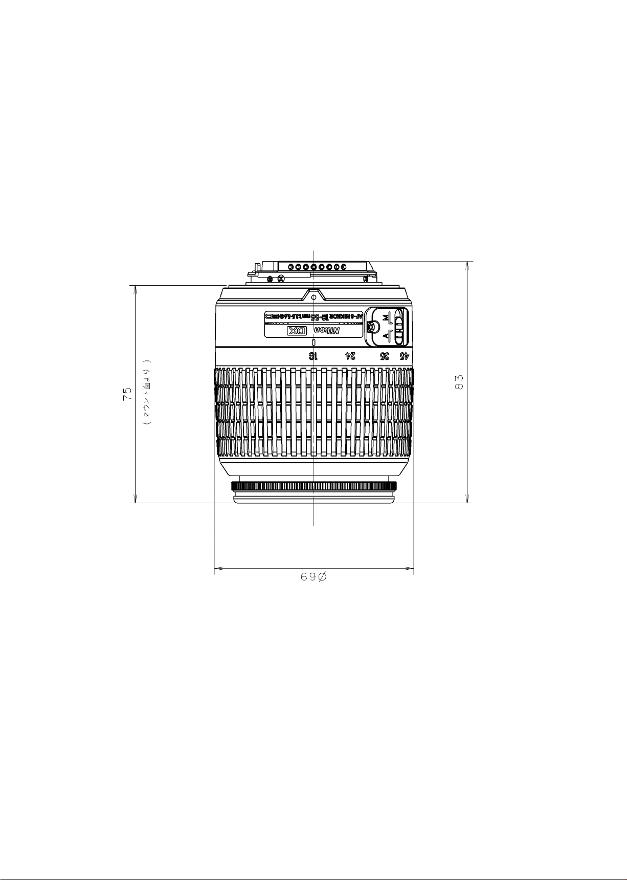
Dimensions: Approx. 69mm dia. x 74mm extension from the camera’s lens-mount ange
Weight: Approx. 210g (7.4 oz)
・Specications and designs are subject to change without any notice or obligation on the part
Page 3
JAA79201-R.3669.A
- D1・ AF-S 18-55/3.5-5.6G -
#68
#113
Disassembly / Assembly / Adjustment
1. Disassembly
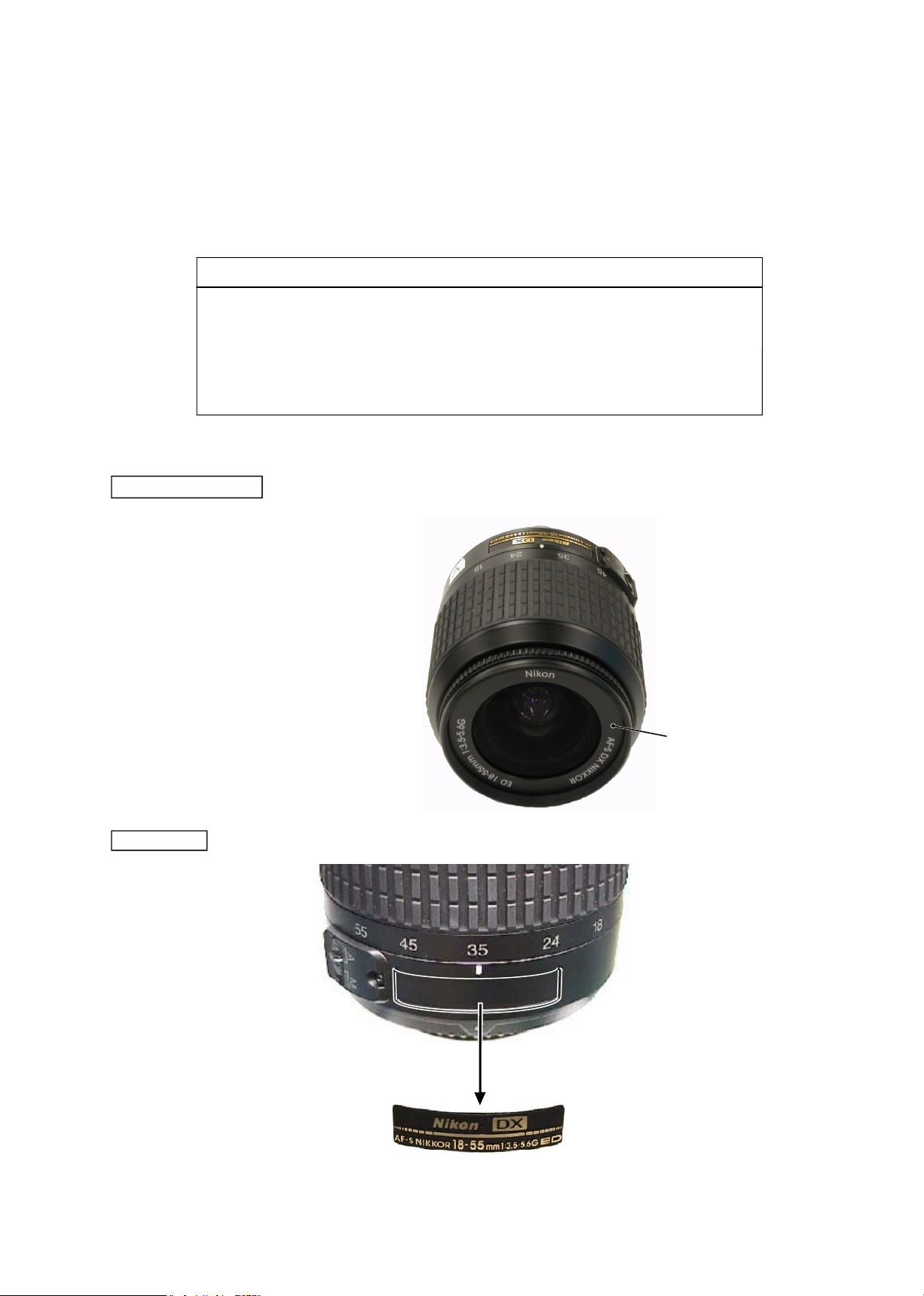
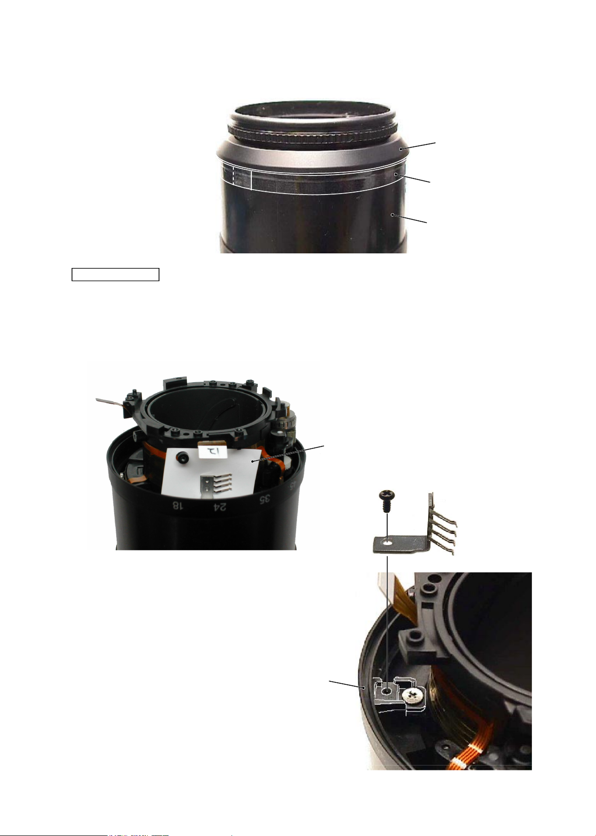
Name plate
Company name ring
Note: Detaching the name plate (#68) is NOT necessary EXCEPT replacing it.
・
The company name ring (#113)
is attached with the both-sided
adhesive tape.
Note:
①
When disassembling, make sure to memorize the processing state of wires and FPC
.
②
Because prototypes are used for "Disassembly/(Re)assembly/Adjustment", they may differ from the actual
products in forms, etc.
③
Because pictures are processed by a special method, they may differ from the actual ones in texture.
・Lead-free solder is used for this product.
・For soldering work, the special solder and soldering iron are required.
・
Do NOT mix up lead-free solder with traditional solder.
・Use the special soldering iron respectively for lead-free solder and lead solder.
They cannot be used in common.
Points to notice for Lead-free solder products
Page 4
JAA79201-R.3669.A
- D2・ AF-S 18-55/3.5-5.6G -
#62
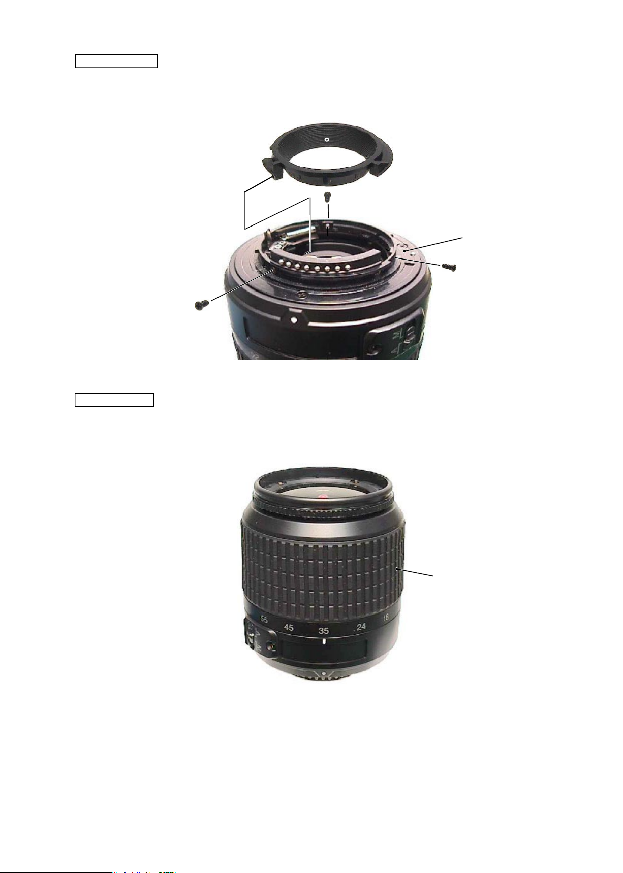
Rear cover ring
・
Take out 3 screws (#91) to remove the rear cover ring (#39).
#39
#91×3
#B27
Rubber ring
・
Remove the rubber ring (#62).
Page 5
JAA79201-R.3669.A
- D3・ AF-S 18-55/3.5-5.6G -
#103
#111×4
#B1
#100A
~
I×n
#52
#67×2
#B27
#B6
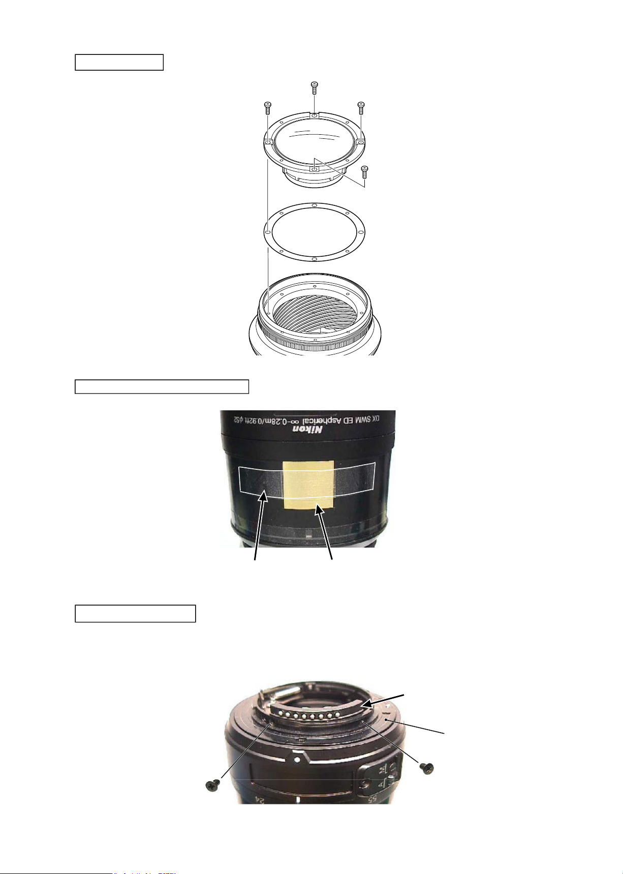
1st lens group
Distance brush hole-sealing plate
Polyester tape
・
Take out 2 screws (#67) of the contact unit (#B6) that is attached to the bayonet mount unit (#B27).
Removal of Contact unit
Page 6
JAA79201-R.3669.A
- D4・ AF-S 18-55/3.5-5.6G -
・
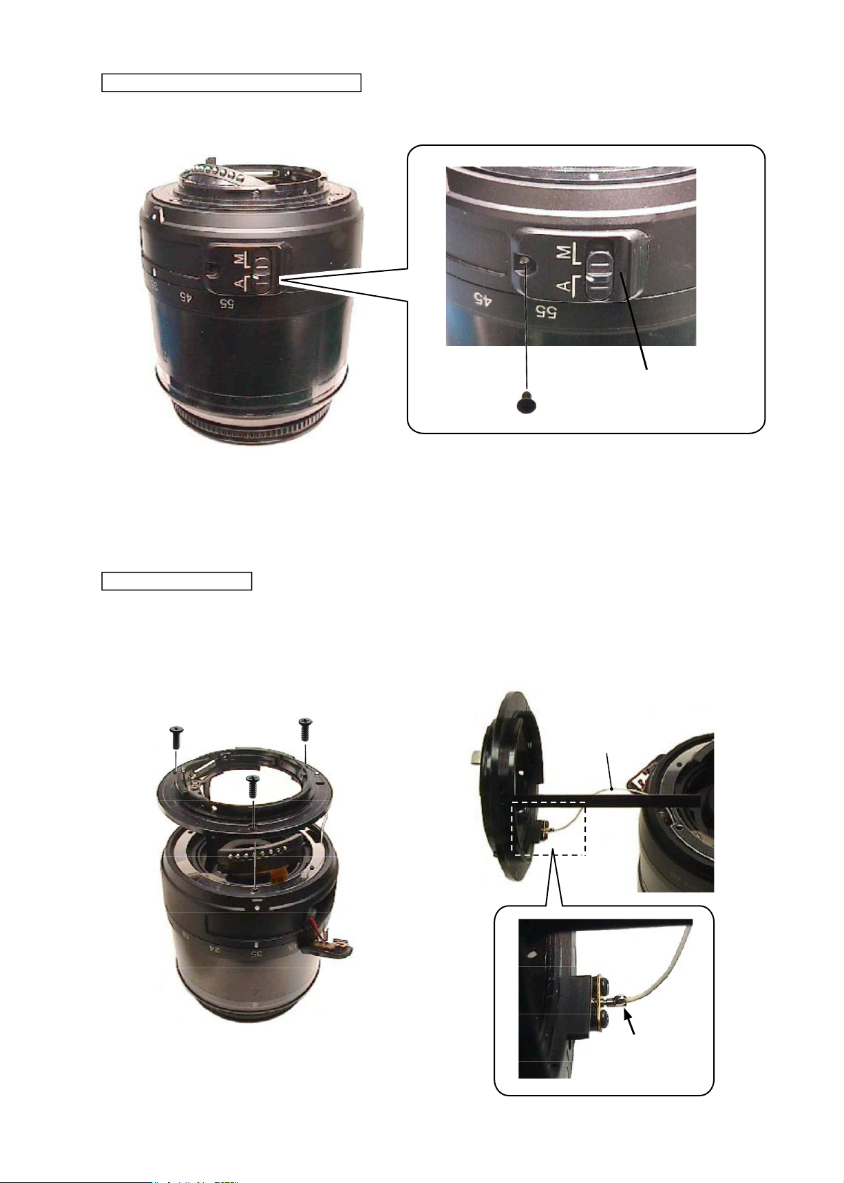
Take out the screw (#155) to remove the M/A change-SW unit(#B22).
#155
Bayonet mount unit
・
Take out 3 screws (#78) of the bayonet mount unit (#B27) to remove the lead wire (#1131).
#1131
Remove the solder.
#78×3
#B27
Removal of M/A change-SW unit
#B22
Page 7
JAA79201-R.3669.A
- D5・ AF-S 18-55/3.5-5.6G -
Washer
#101A~J×n
#1131
・
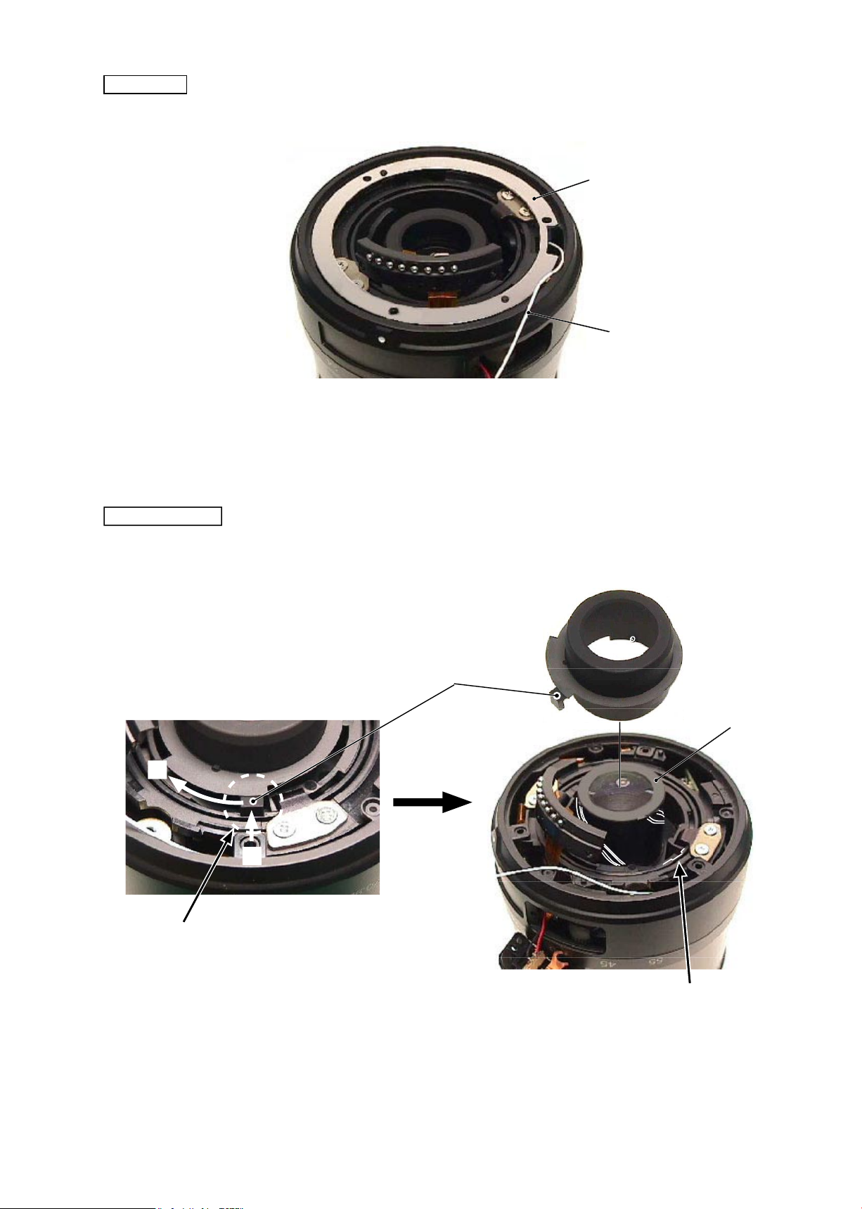
Remove the washers
(
#101A
~
J×n).
Flare cutter
・
Release the key part of the are cutter (#46) from the key-groove of the cam tube, then remove the are
cutter.
#46
Key part
Key-groove of Cam tube
#B24
Release the key part from the key-groove.
・
Set the zoom position to WIDE-end. While
pressing the pointed tip of the key inward,
remove the key by turning clockwise.
①
→
②
①
②
Page 8
JAA79201-R.3669.A
- D6・ AF-S 18-55/3.5-5.6G -
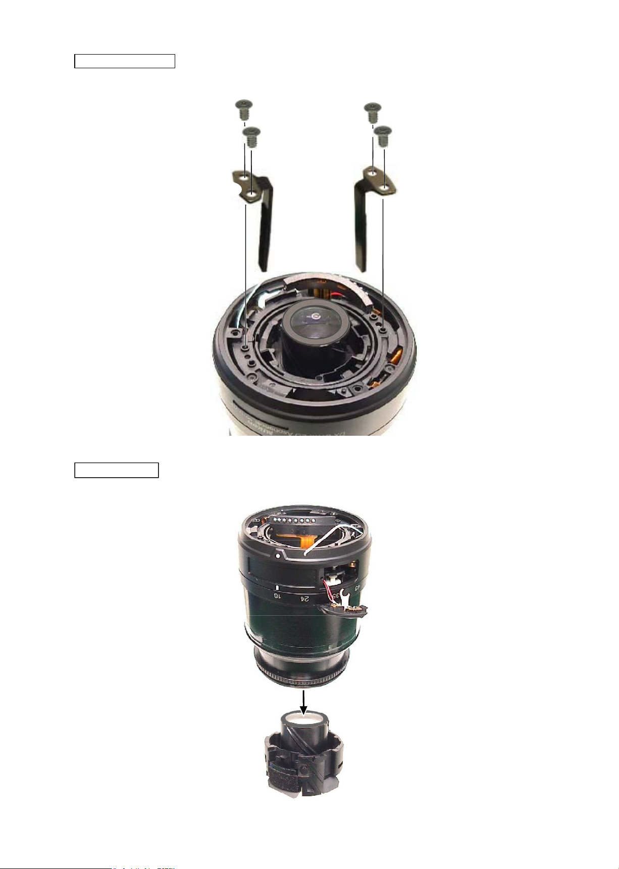
Straight key unit
#86×2
#B25A
#86×2
#B25B
2nd lens group
#B24
Page 9
JAA79201-R.3669.A
- D7・ AF-S 18-55/3.5-5.6G -
Rear xed tube
・
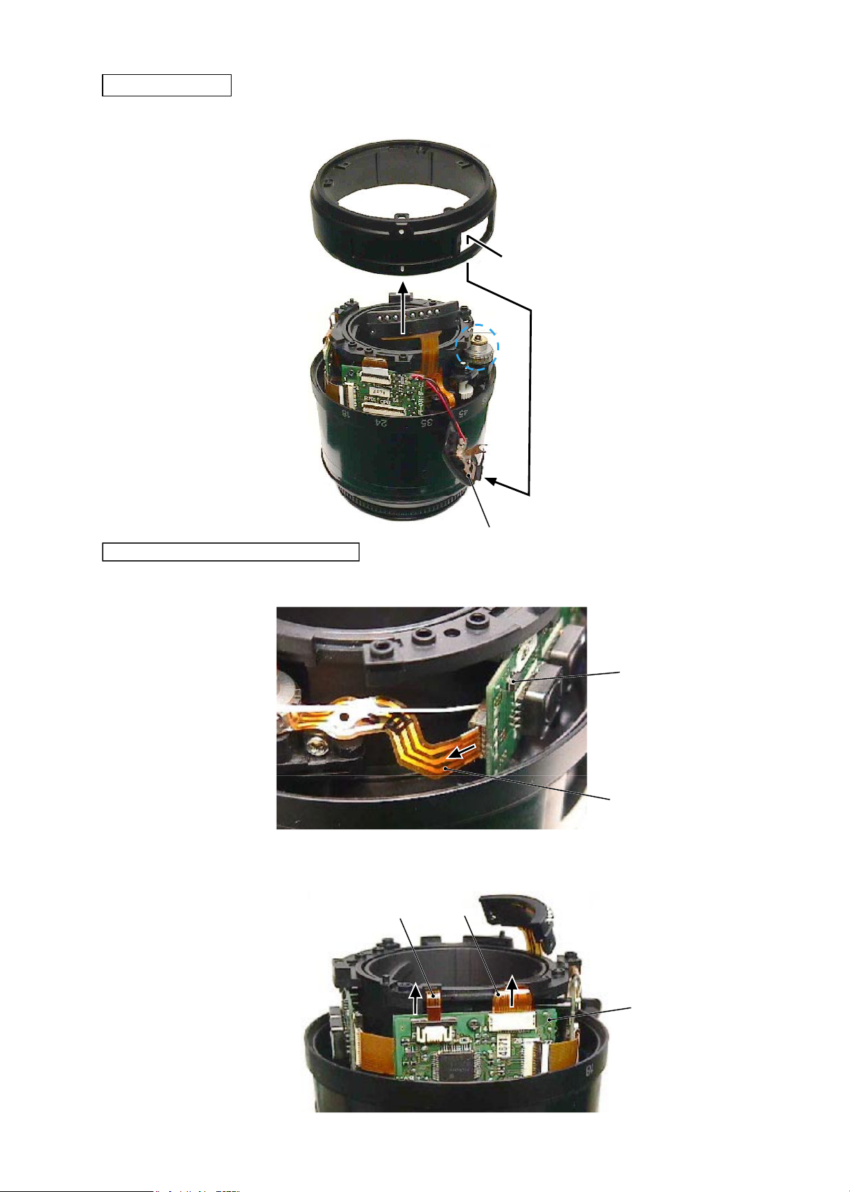
Set the M/A change-SW unit (#B22) to A mode. Detach it from the window of the rear xed tube (#57) and
remove the rear xed tube.
#B22
#57
Removal of FPC from Main-PCB unit
・
Remove the SWM unit (#B501) from the main-PCB unit (#B1001).
#B501
#B1001
・
Remove the contact unit (#B6) and MR unit (#B7) from the connector of the main-PCB unit (#B1001).
#B1001
#B7
#B6
Note: Do NOT touch "A" part directly
with hand.
A
Page 10
JAA79201-R.3669.A
- D8・ AF-S 18-55/3.5-5.6G -
・
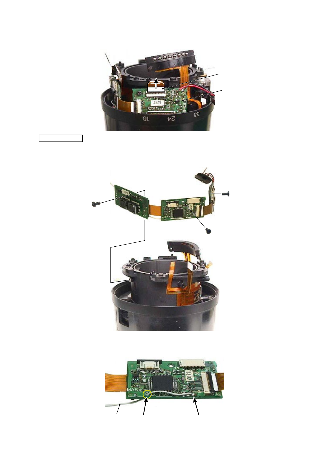
Remove the zoom/distance FPC from the connector of the main-PCB unit (#B1001).
#B1001
Zoom/distance FPC
・
Remove the main-PCB unit (#B1001).
#89
#89
#89
#B1001
Main PCB unit
・
Remove the lead wire (#1131) from the main-PCB unit (#B1001).
Hole
Remove the solder.
#1131
Page 11
JAA79201-R.3669.A
- D9・ AF-S 18-55/3.5-5.6G -
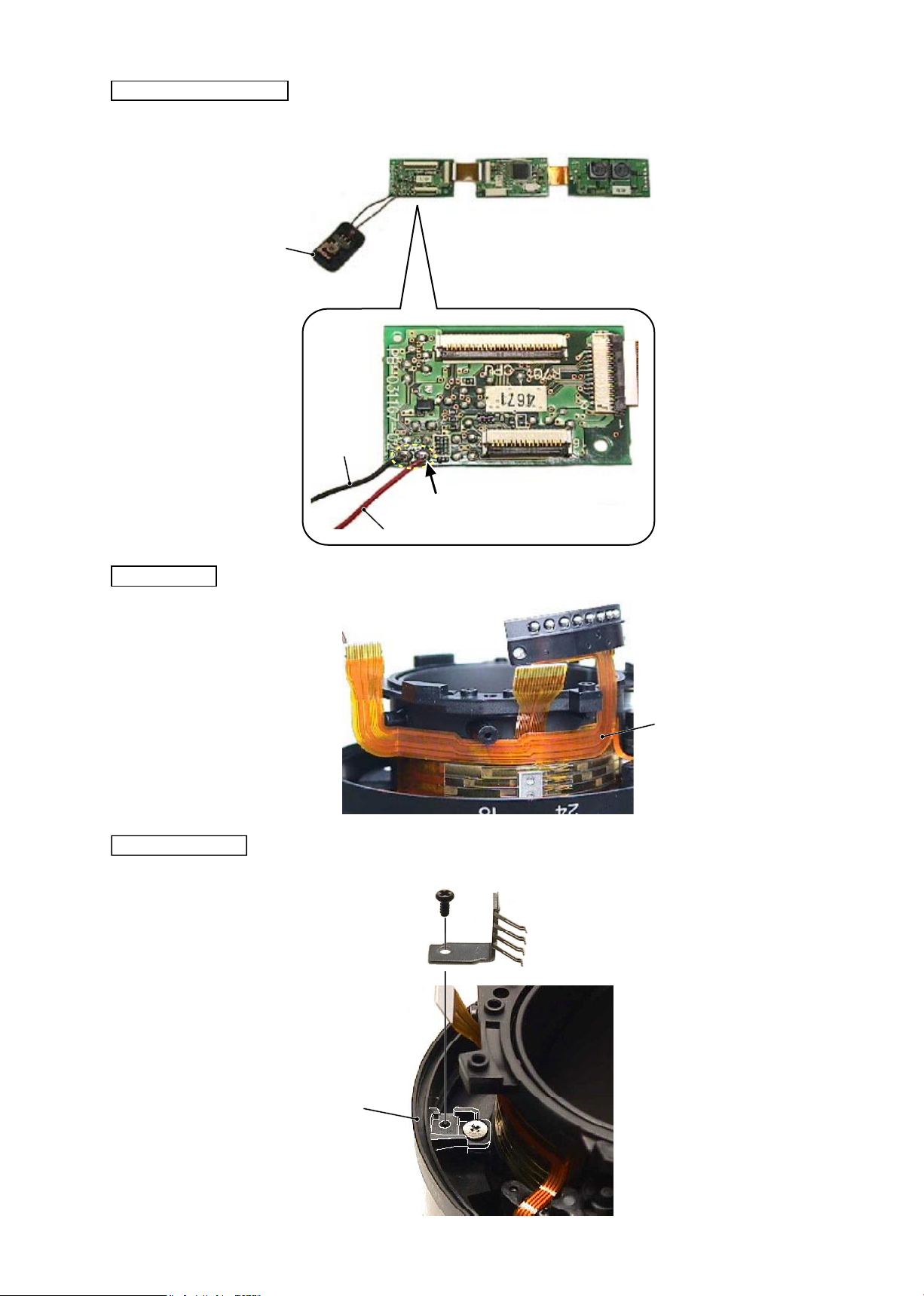
Contact unit
・
Remove the contact unit (#B6).
#B6
M/A change-SW unit
・
Remove 2 lead wires of the M/A change-SW unit (#B22) from the main PCB unit (#B1001).
#B22
Remove the solder.
#B1001
Black
Red
Zoom brush unit
#89
#B8
#52
Zoom brush unit
Page 12
JAA79201-R.3669.A
- D10 ・ AF-S 18-55/3.5-5.6G -
・
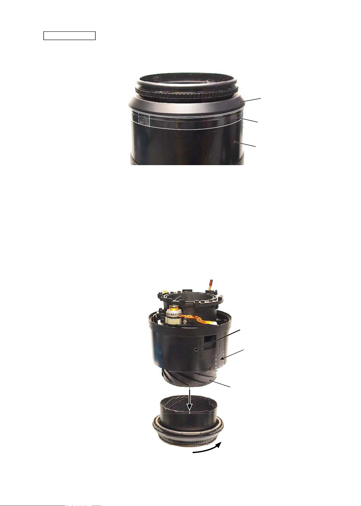
Remove the polyester tape (#77) from the zoom ring (#52).
#77
#52
Zoom cover ring
Filter ring unit
・
While releasing the engagements of 2 keys of the focus ring, turn the lter ring unit (#B20) in the direction of
the arrow to remove it.
#
B20
Helicoid ring
Key of focus ring
Zoom ring
Page 13
JAA79201-R.3669.A
- D11 ・ AF-S 18-55/3.5-5.6G -
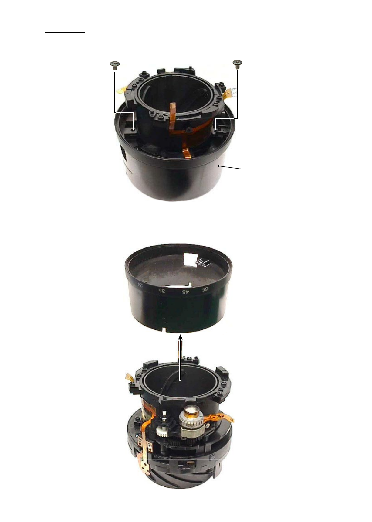
Zoom ring
#102×2
・
Take out 2 screws (#102) that attach the zoom ring (#52).
#52
・
Detach the zoom
ring (#52) from the xed tube unit.
#52
Fixed tube unit
Page 14
JAA79201-R.3669.A
- D12 ・ AF-S 18-55/3.5-5.6G -
#56
②
MR unit
・
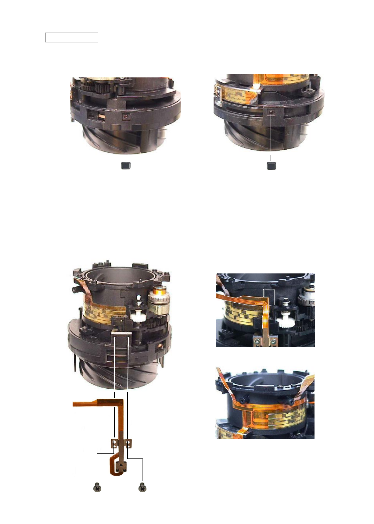
Remove the MR unit (#B7) from the xed tube.
#56
・
Remove 2 silicon rubbers (#56) from the square grooves of the xed tube.
・
Remove the FPC of the MR unit from the xed tube.
#72
#72
#B7
Fixed tube unit
①
Silicon rubber
Page 15
JAA79201-R.3669.A
- D13 ・ AF-S 18-55/3.5-5.6G -
Gear
③
SWM unit
#B501
Do NOT touch "A" part.
A
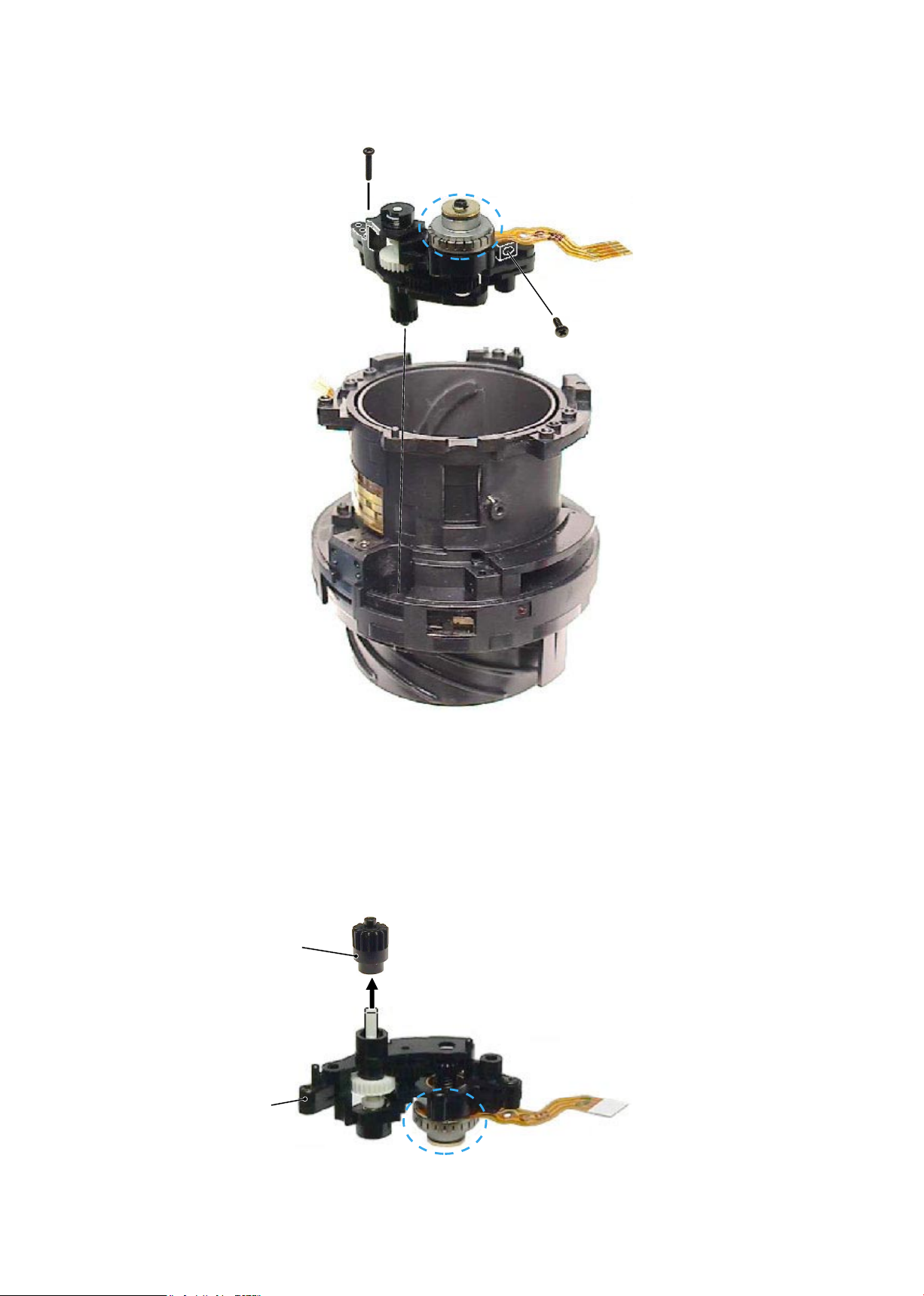
・
Remove the SWM unit (#B501) from the xed tube.
A
#132
#131
Fixed tube
#B501
④
Gear
Note: Do NOT touch "A" part directly with hand.
Page 16
JAA79201-R.3669.A
- A1・ AF-S 18-55/3.5-5.6G -
2. Assembly / Adjustment
Fixed tube unit
Helicoid ring
After assembling
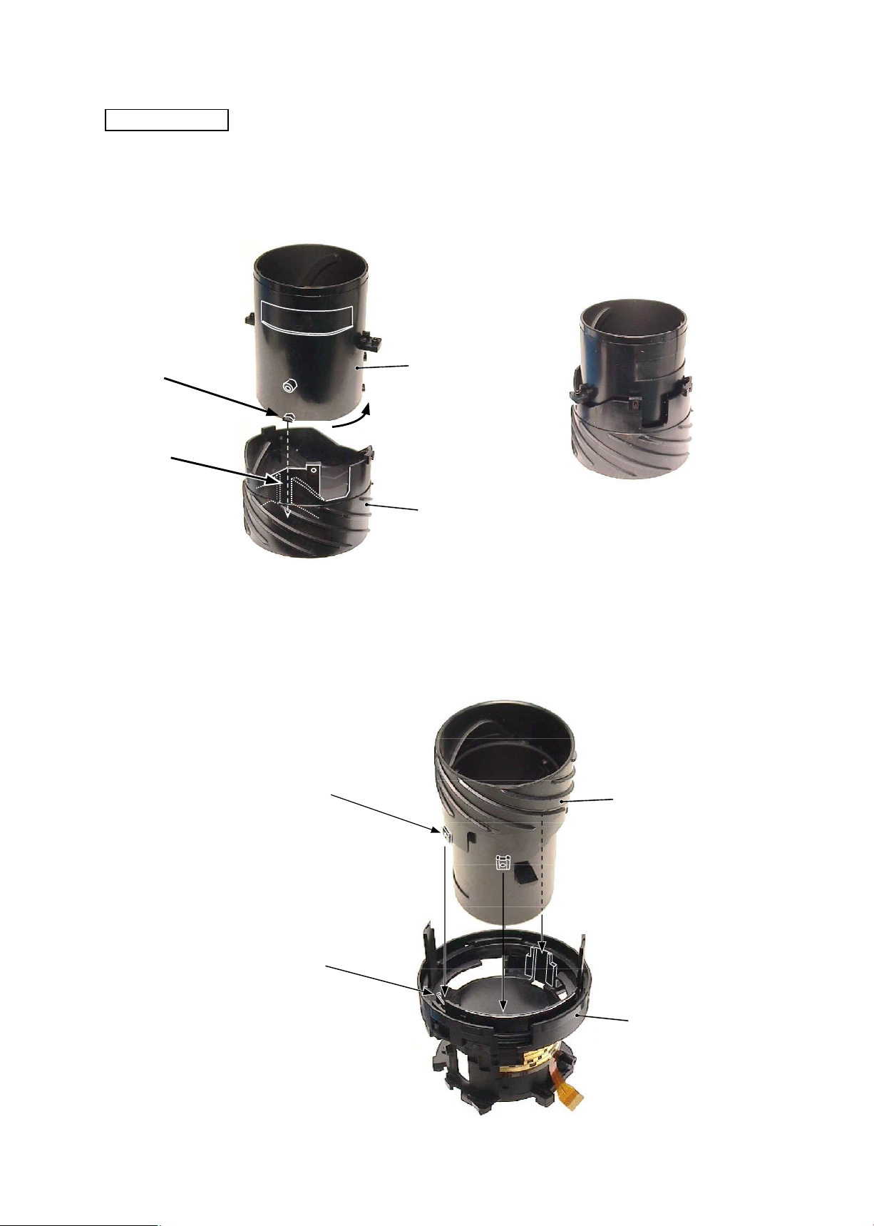
・
Align the cam ring (3 grooves between convex portions on the outer diameter surface) with the helicoid ring
(3 convex cams on the inner diameter surface) and assemble the rings by turning them.
Cam ring
①
Cam tube unit (Helicoid ring, Cam ring)
・
With the cam tube unit (3 outer convex portions) being at the full up WIDE position, assemble the xed tube
(3 inner grooves between cams).
Note:
The cam ring and helicoid ring are
NOT prepared as single part of RP.
②
Cam tube unit / Fixed tube
Cam tube unit
Fixed tube
Convex portion on
the outer diameter
surface
Outer convex portion
Groove between inner cams
Page 17
JAA79201-R.3669.A
- A2・ AF-S 18-55/3.5-5.6G -
#513
③
SWM unit
・
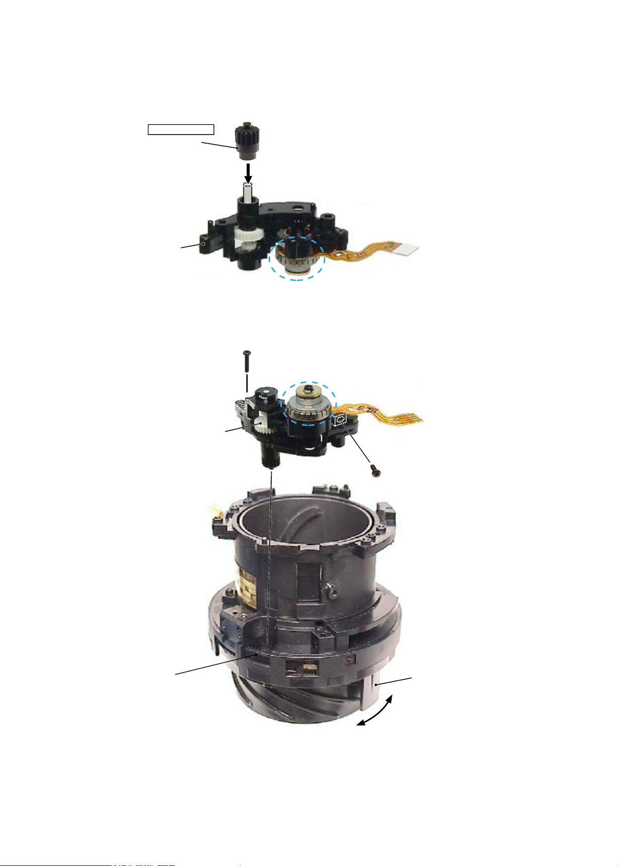
Assemble the gear (#513) into the SWM unit (#B501).
#B501
Do NOT touch "A" part.
A
・
Assemble the SWM unit into the xed tube.
A
・
Raise the clutch gear with tweezers, and check the engagement of the segment gear tube and the ear (#513)
by turning the MF ring.
・
Raise the clutch gear with tweezers, and check it moves back downwards smoothly.
#132
#131
Clutch gear
MF ring
Grease: MZ-800S
Note: Do NOT touch "A" part.
Segment gear tube
Page 18
JAA79201-R.3669.A
- A3・ AF-S 18-55/3.5-5.6G -
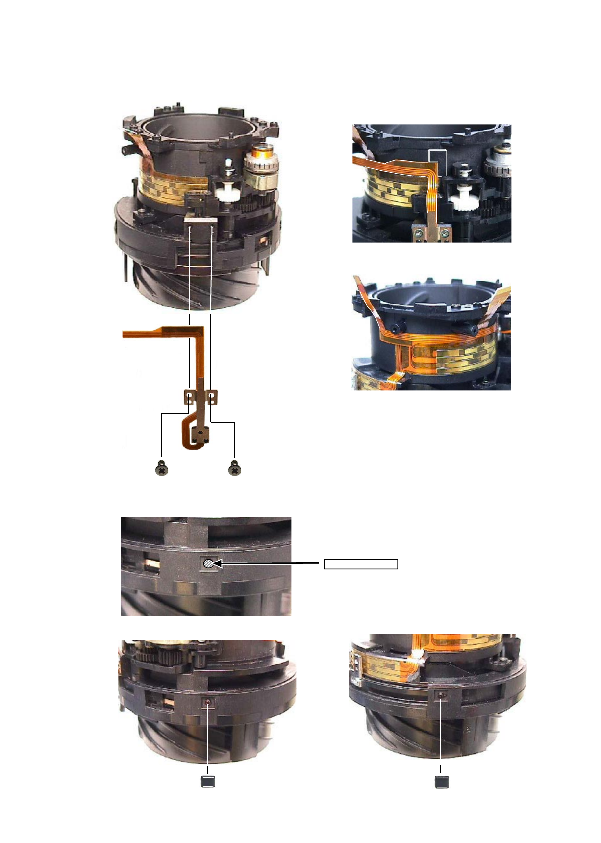
#56
④
MR unit
・
Assemble the MR unit (#B7) into the xed tube.
#56
・
Put the silicon rubbers (#56) into 2 square grooves of the xed tube, and press them (with ngers).
・
Attach the FPC of the MR unit on the xed tube,
and press it with ngers.
#72
#72
#B7
Square groove×2
Adhesive:
Screwlock
Page 19
JAA79201-R.3669.A
- A4・ AF-S 18-55/3.5-5.6G -
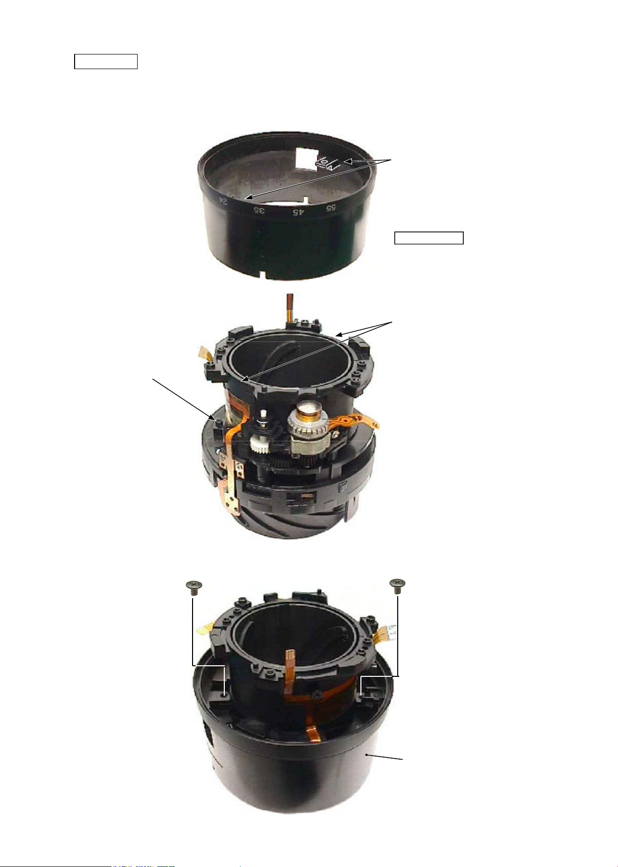
Zoom ring
#102×2
・
Align 2 notches of the xed tube with 2 convex portions of the zoom ring (#52) to assemble them. Then
turn the zoom ring, and t 2 convex portions of the cam ring into 2 holes of the zoom ring.
#52
・
Fix the zoom ring (#52) with 2 screws (#102), and check the smoothness of the zoom ring’s movement.
Fixed tube unit
#52
Apply to the sliding part of the
inner diameter surface.
Grease: MZ-800S
Convex portion
Notch
Convex portion of cam ring
Page 20
JAA79201-R.3669.A
- A5・ AF-S 18-55/3.5-5.6G -
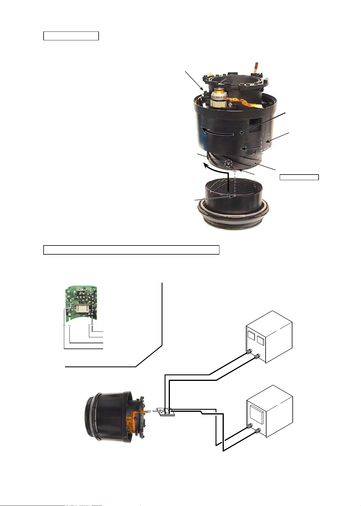
Filter ring unit
#
B20
①
Turn the zoom ring in the direction
of the arrow (TELE-side).
②
While lifting the clutch gear, turn
the key of the focus ring all the
way in the direction of the arrow.
③
Align the reference line of the lter
ring unit (#B20) with “A” part of
the helicoid ring, and turn the lter
ring until it clicks.
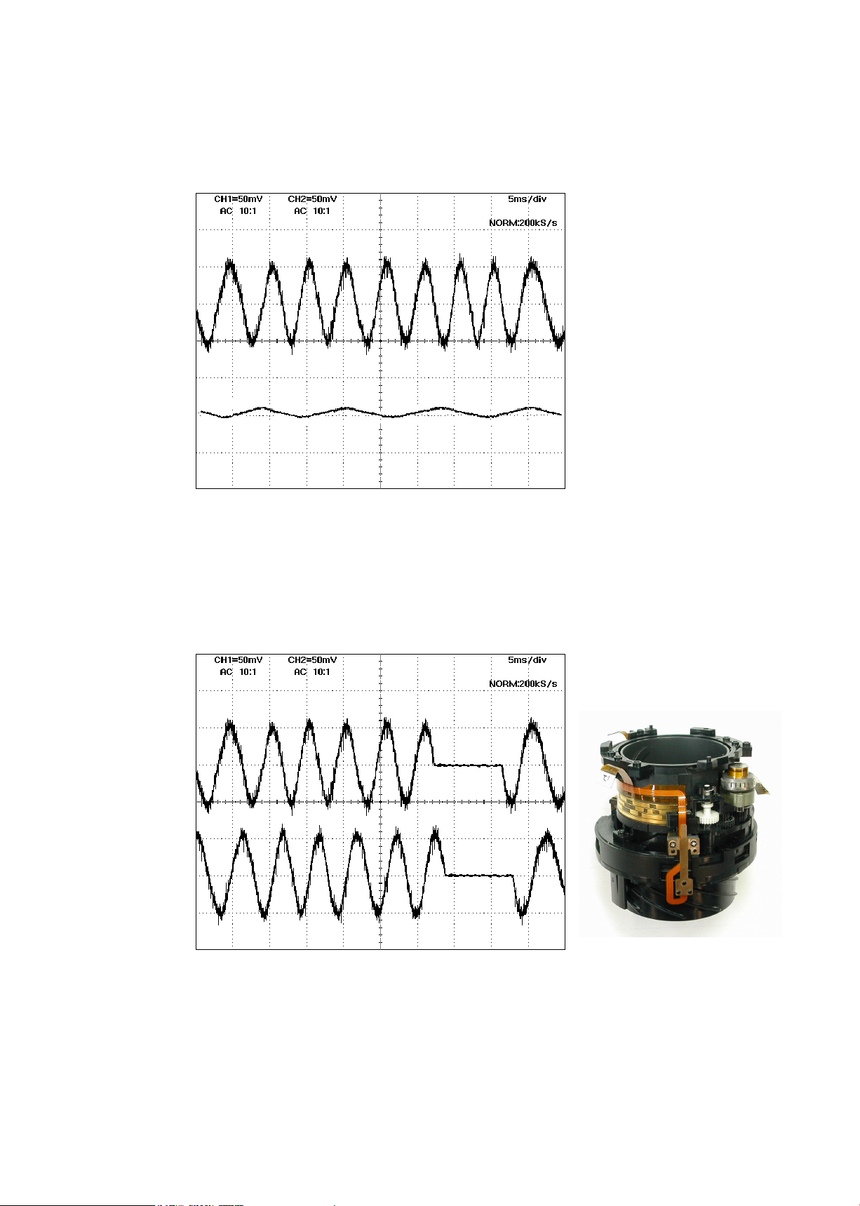
Inspection and adjustment of output waveform of MR encoder
Helicoid ring
Apply to the sliding part
of the outer diameter
surface.
Grease: MZ-800S
Oscilloscope
(2ch type)
Rated voltage power-supply
Set value
5.0 V
100 mA
(+)
(
GND
)
・
【
Attachment diagram
】
Self-made tool
Oscilloscope
(2ch)
Oscilloscope
(1ch)
Rated voltage power-supply
(+)
Rated voltage power-supply
(-)
Self-made tool that is created with
the main PCB of AF-S 24-85
SWM unit
A
Key of Focus ring
Zoom ring
Reference line
▽
-mark
Page 21
JAA79201-R.3669.A
- A6・ AF-S 18-55/3.5-5.6G -
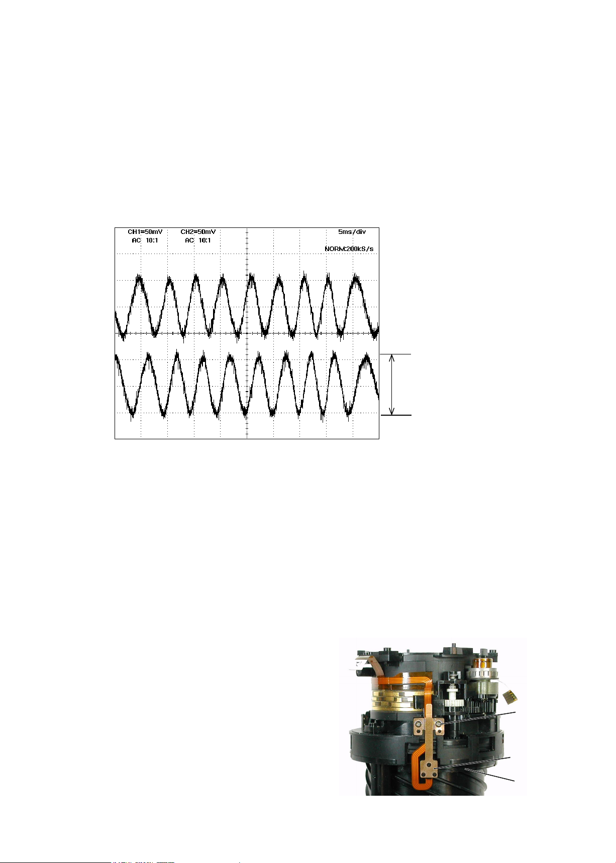
● Oscilloscope setting
V/Div (ch1) : 50 mV
V/Div (ch2) : 50 mV
Coupling : AC
Time/Div : 5 m Sec
Trigger Mode : NORMAL
Trigger Coupling : AC
・
How to inspect and adjust:
①
Conrm that the electric current and voltage of the connected rated voltage power-supply are set values, then
turn it ON.
②
Set the oscilloscope. While holding the white gear of the SWM unit with tweezers, etc, up towards the
bayonet side, turn the focus ring manually.
Note: The waveform varies according to the rotational speed of the focus ring. So change "Time/Div” setting
accordingly.
③
In case large waveform-noise (as shown in Fig. 1) is detected, use the FILTER function.
How to set FILTER function (e.g. DL1540 manufactured by YOKOGAWA
)
1. Press the FILTER button.
2. Select “Smooth” of the menu on screen and turn it ON.
Amplitude
CH1
CH2
Fig.1
⑥
In case the amplitude is small, disassemble up to the
stage of the zoom ring. Then if the deformation is
detected in the MR head, correct the deform of the
MR head. On the other hand, if such correction is
impossible or no deformation is detected, replace the
MR unit. (Fig.2)
Note: When adjustments are made, prevent the
magnetic surface and MR head from touching the
magnetized driver bit. Otherwise, the magnetic
data may be damaged.
MR head
Magnetic
surface
#79×2
Fig.2
Standard:
Amplitude of all pulses/
waveforms is 80mV or more.
Note:
Check the waveform by moving the
focus ring back and forth from the
innity-end to the close-end positions
entirely.
Page 22
JAA79201-R.3669.A
- A7・ AF-S 18-55/3.5-5.6G -
Fixed tube unit
Fig.1
CH1
CH2
Fig.2
CH1
CH2
<
Ref.
>
● As shown in Fig. 1,
if the amplitude of only either CH1 or CH2 is small, one of the 2 screws (#218) may be
loosened, so check for it. If this is not the case, the MR head may malfunction, so replace the MR holder
unit and make a readjustment.
●
As shown in Fig. 2,
if the amplitude partially drops between the innity and the close-distance, the
magnetic data of the tape may be damaged. So replace the main xed tube unit and make a readjustment.
Replacing only the magnetic surface is impossible.
⑦ Turn off the rated voltage power-supply.
Page 23
JAA79201-R.3669.A
- A8・ AF-S 18-55/3.5-5.6G -
・
While pressing the zoom aperture ring on the zoom ring (#52), attach the polyester tape (#77) to cover the
boundary line of the entire circumference of the 2 rings.
#77
#52
Zoom cover ring
Zoom brush unit
・
Assemble the zoom brush unit (#B8) into the zoom ring (#52).
Note: In order to prevent the brush from being bent when assembled, use the Z-brush
insertion sheet (J11316) and assemble the zoom brush unit (#B8).
#89
#B8
#52
Z brush insertion sheet
(J11316)
★
(6×30
)
TA-0012
★:
Newly prepared RJ tool
Page 24
JAA79201-R.3669.A
- A9・ AF-S 18-55/3.5-5.6G -
Contact unit
・
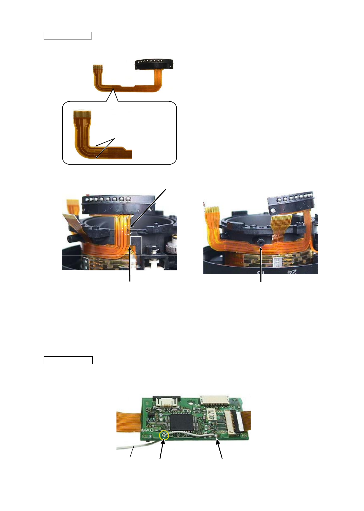
Valley fold the FPC of the contact unit (#B6) with
ngers to crease it. Then attach the contact unit to
the xed tube.
#B6
Align the FPC-mark with the edge of the xed tube.
Main PCB unit
・
After soldering the lead wire (#1131) on the main PCB unit (#B1001), pass the wire through the hole of the
PCB.
Hole
Solder
#1131
Make a valley fold from the 2
points to crease FPC.
Surface for positioning
Surface for positioning
Page 25
JAA79201-R.3669.A
- A10 ・ AF-S 18-55/3.5-5.6G -
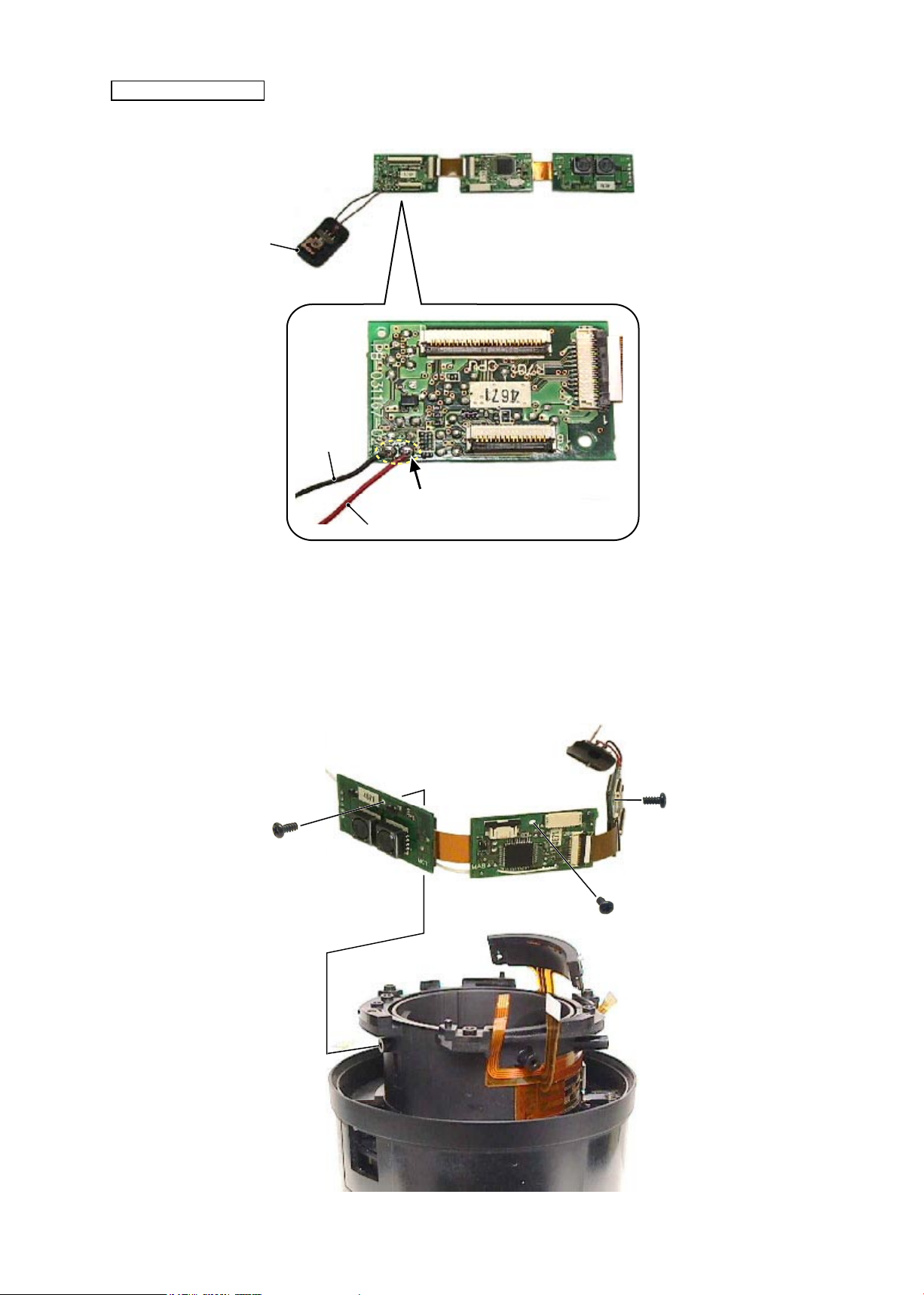
M/A change SW unit
・
Solder 2 wires of the M/A change SW unit (#B22) on the main PCB unit (#B1001).
・
Be sure to place the main PCB unit (#B1001) on the surface for positioning of the xed tube, then x it
with 3 screws (#89×3).
#B22
Solder
#89
#89
#89
#B1001
#B1001
Black
Red
Page 26
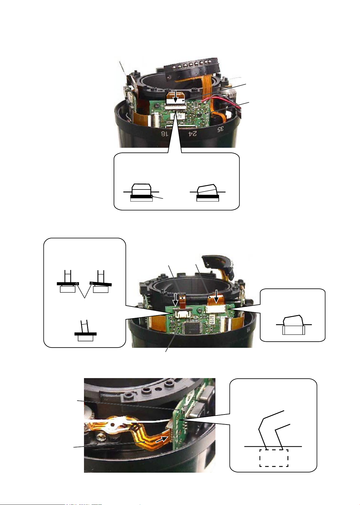
JAA79201-R.3669.A
- A11 ・ AF-S 18-55/3.5-5.6G -
・
Insert the zoom/distance FPC into the connector of the main PCB unit (#B1001) to connect it.
・
Insert the contact unit (#B6) and GMR unit (#B7) into the connector of the main PCB unit (#B1001) to
connect them.
・
Insert the SWM unit (#B501) into the connector of the main PCB unit (#B1001) to connect it.
Diagram of NG insertion:
No slack of lid No slanted insertion.
Lid
#B1001
#B501
Zoom/distance FPC
Diagram of NG insertion:
No slanted insertion.
#B1001
#B1001
#B7
#B6
Diagram of NG insertion:
No slanted insertion.
No slack of lid
Lid
Diagram of NG insertion:
No slanted insertion.
Page 27
JAA79201-R.3669.A
- A12 ・ AF-S 18-55/3.5-5.6G -
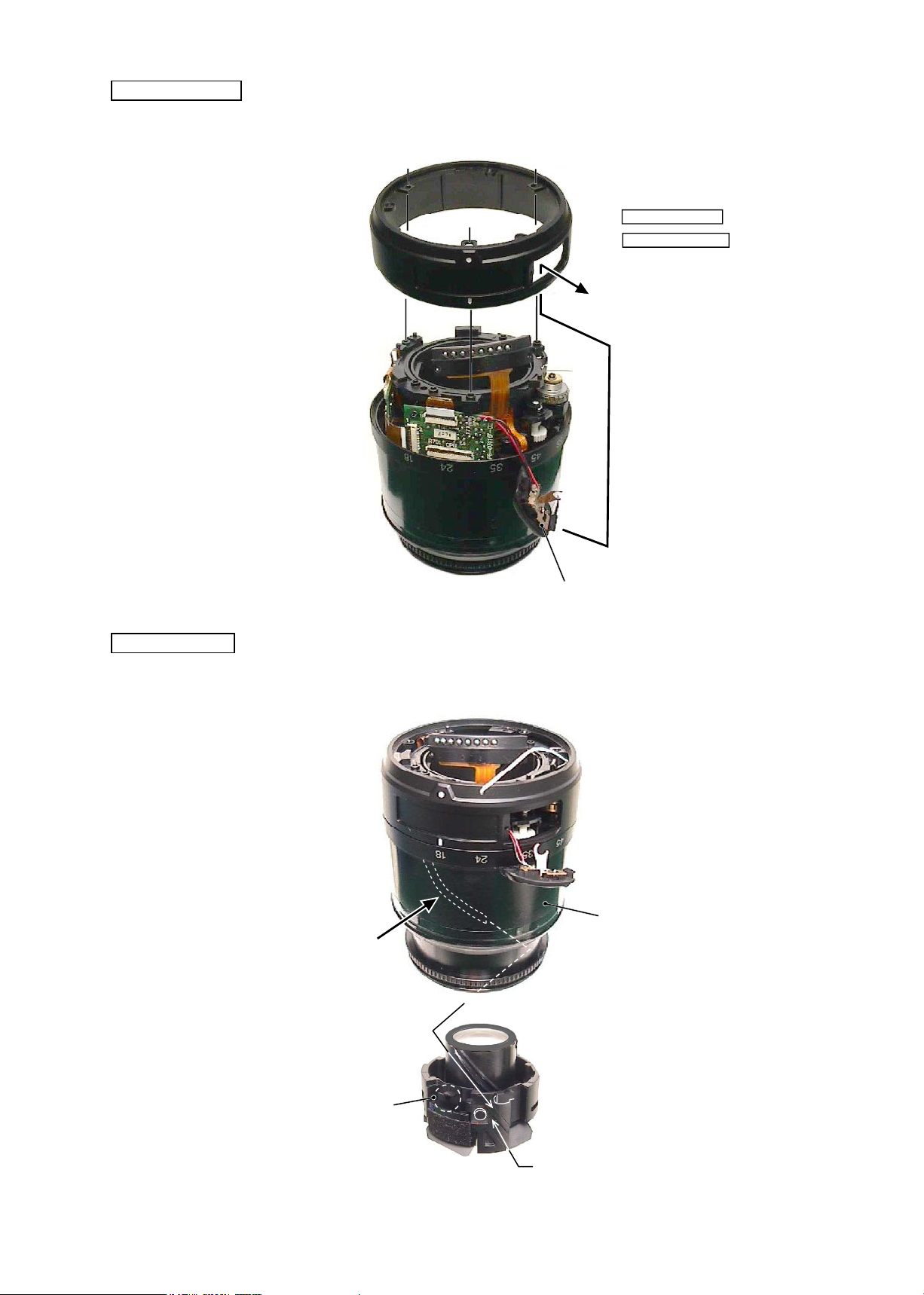
2nd lens group
Rear xed tube
・
Set the M/A change SW unit (#B22) to "A" mode. Pass this unit through the window of the rear xed tube
(#57) and assemble them.
#B22
#57
#B24
3 concave portions
3 convex portions of the inner
diameter surface
Lever of aperture actuating
plate
・
Set the zoom ring (#52) to WIDE side. Then assemble the 2nd lens group (#B24) into it by aligning convex
portions with the concave portions of #B24.
#52
Grease: OS-30MF
Apply to the overall sliding part.
Grease: MZ-800S
Page 28
JAA79201-R.3669.A
- A13 ・ AF-S 18-55/3.5-5.6G -
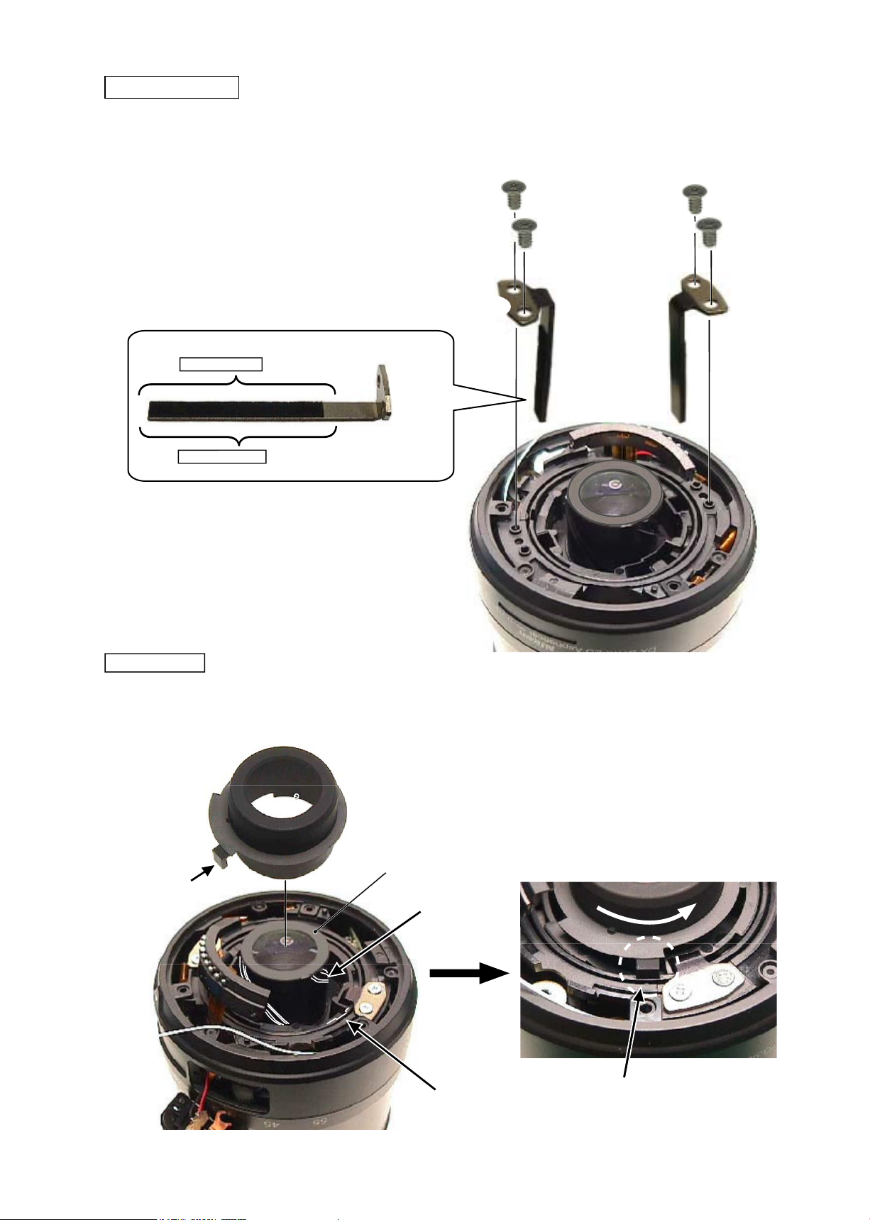
Straight key unit
・
After applying the grease to the straight key unit A (#B25A) and straight key unit B (#B25B), x 4 screws
(#86) by aligning setscrew holes and key grooves of the xed tube unit.
#86×2
#B25A
#86×2
#B25B
Flare cutter
#B25A
#B25B
・
Align 3 cams of the 2nd lens group (#B24) with 3 convex portions of the are cutter (#46) to assemble
them. Then put the key part into the key groove of the cam tube.
#46
Key part
Key groove of the cam tube
#B24
Put the key part into the key groove.
Grease: I-40
Grease: I-40
Cam
Page 29
JAA79201-R.3669.A
- A14 ・ AF-S 18-55/3.5-5.6G -
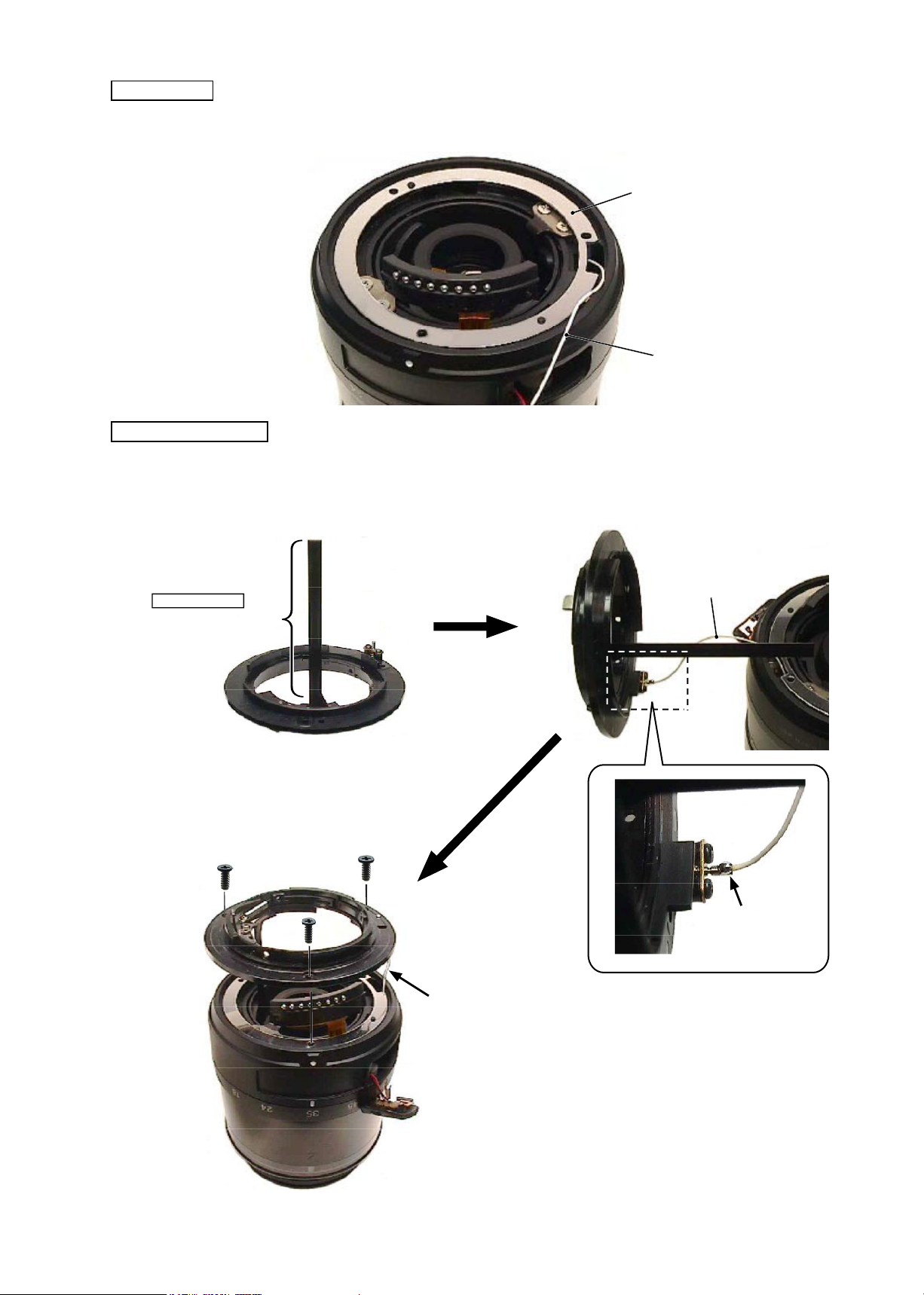
Washers
#101A~J×n
Bayonet mount unit
・
After applying the grease to the lever of the bayonet mount unit (#B27), solder the lead wire (#1131) and
x 3 screws (#78) to assemble.
#1131
・
Fix the washers
(
#101A
~
J×n).
#1131
#B27
Solder
#78×3
Put the lead wire into the hole.
Apply to the overall
contacting surface
Grease:G92KA
Page 30
JAA79201-R.3669.A
- A15 ・ AF-S 18-55/3.5-5.6G -
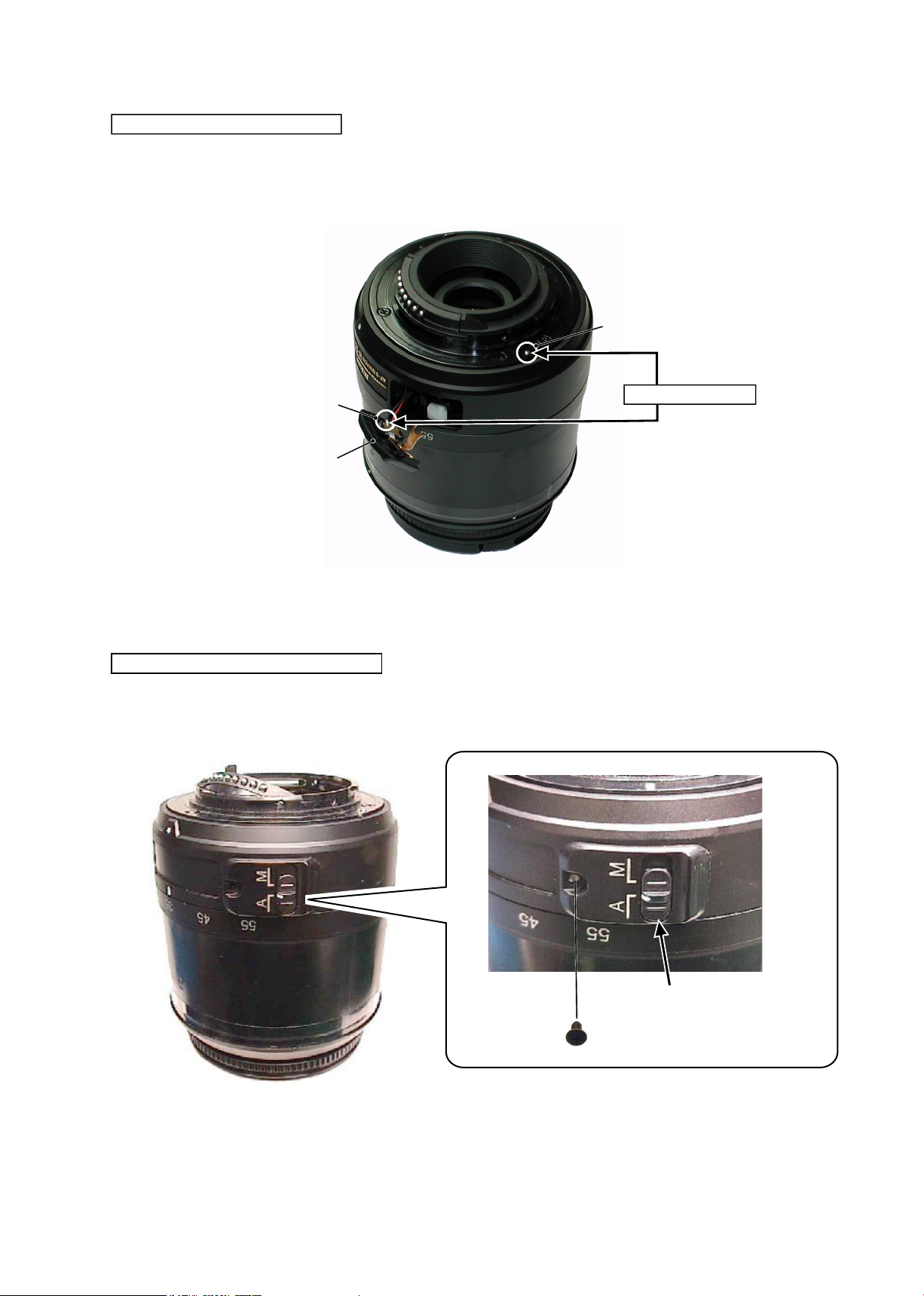
Attachment of M/A change SW unit
・
Attach the M/A change SW unit (#B22) with the screw (#155).
#155
Check if the M/A change SW
and focusing operation work
properly.
Ground line continuity check
・
Check (electric) continuity of the ground line from the GND pin of the bayonet mount to the M/A change
SW unit (#B22).
Ground line (black)
#B22
GND
Continuity tester
Page 31
JAA79201-R.3669.A
- A16 ・ AF-S 18-55/3.5-5.6G -
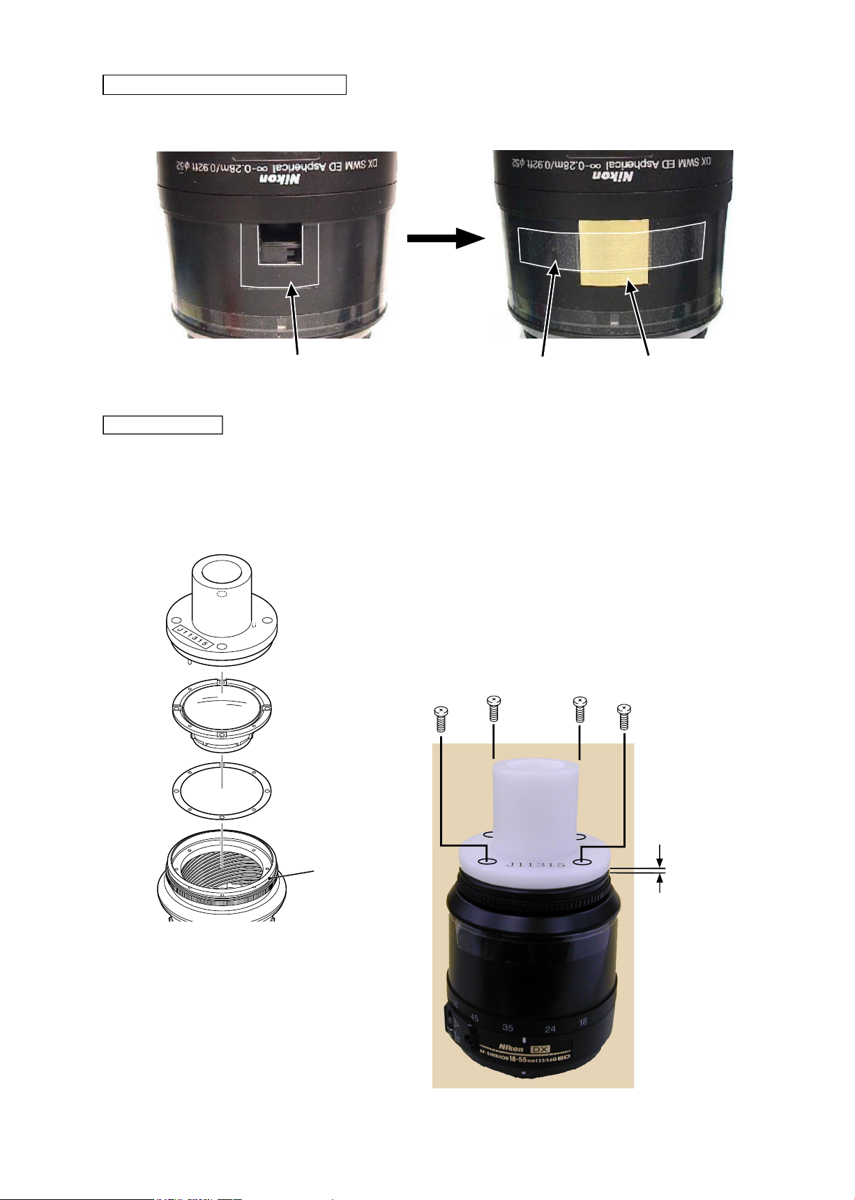
Distance brush hole-covering plate
・
Assemble the distance brush hole-covering plate (#103) into the zoom ring (#52), and attach the polyester
tape.
#103
Polyester tape
#52
1st lens group
・
Put the 1st lens group (#B1) and washers (#100A
~
I×n) by tting their holes into the pins of the 1st lens-
group assembling tool (J11315), and assemble them into the lter ring (#B20). Then x 4 screws (#111).
#111×4
#B1
#100A
~
I×n
(10×30
)
TA-0011
1st lens group assembling tool
(J11315)
★
★
: Newly prepared tool as RJ
#B20
Note: Gap should be
approx. 1 mm or less.
1mm or less
Page 32
JAA79201-R.3669.A
- A17 ・ AF-S 18-55/3.5-5.6G -
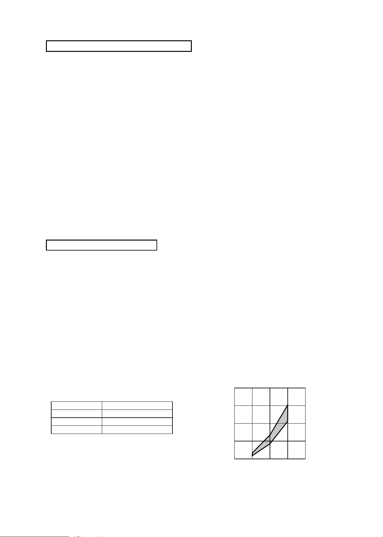
1. Turn the focus ring all the way to the innity-end.
2. Fix the aperture lever so that the aperture becomes full.
3. Read each value of WIDE and TELE sides.
4. Calculate as follows:
(A-B)
÷2.8=C A= Value at TELE side
B= Value at WIDE side
C= Adjustment amount (mm) of the washer (#100) of the 1st lens group
5. Adjust the washer (#100) by increasing/decreasing by the above value of C. If C is plus, increase the
thickness of it, while it is minus, decrease the thickness of it. (ref. Page A16)
Note:
When the washer (#100) is put, place a thin washer between thick washers.
1. Turn the focus ring all the way to the innity-end.
2. Fix the aperture lever so that the aperture becomes wide open.
3. Read the value of Wide or Tele side.
4. Remove the bayonet mount.
5. Adjust the washer (#101) by increasing/decreasing by the difference from the standard value. If the
difference is plus, increase the thickness of it, while it is minus, decrease the thickness of it. (ref. Page
A14
)
Focal length
(f)
Standard (mm)
18 mm
+
0.18
~+
0.33
35 mm
+
0.85
~+
1.35
55 mm
+
2.12
~+
3.04
0
18 35 55
( f )
( mm )
1.0
2.0
3.0
4.0
Adjustment (Division) of Focus movement (T, W)
Adjustment of F.F.D (Back focus)
Page 33
JAA79201-R.3669.A
- A18 ・ AF-S 18-55/3.5-5.6G -
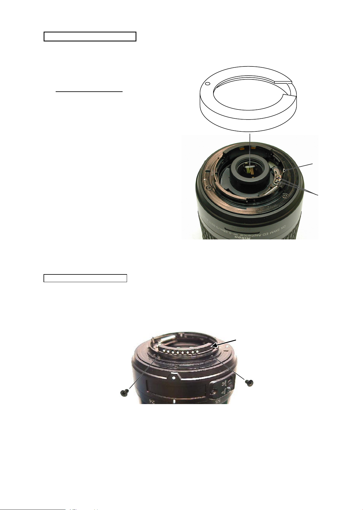
・
Fix the contact unit on the bayonet mount unit (#B27) with 2 screws (#67).
Attachment of Contact unit
#67×2
Contact unit
①
Mount the tool (J18004-1) and check the aper
-
ture diameter.
Standard: Full aperture
②
In case it is out of standard, adjust the position
of the aperture lever (#23) by loosing 2
screws (#93).
J18004-1
Aperture diameter adjustment
#93 × 2
#23
Page 34
JAA79201-R.3669.A
- A19・AF-S 18-55/3.5-5.6G -
AF-S 18-55 inspection and adjustment program (J18378)
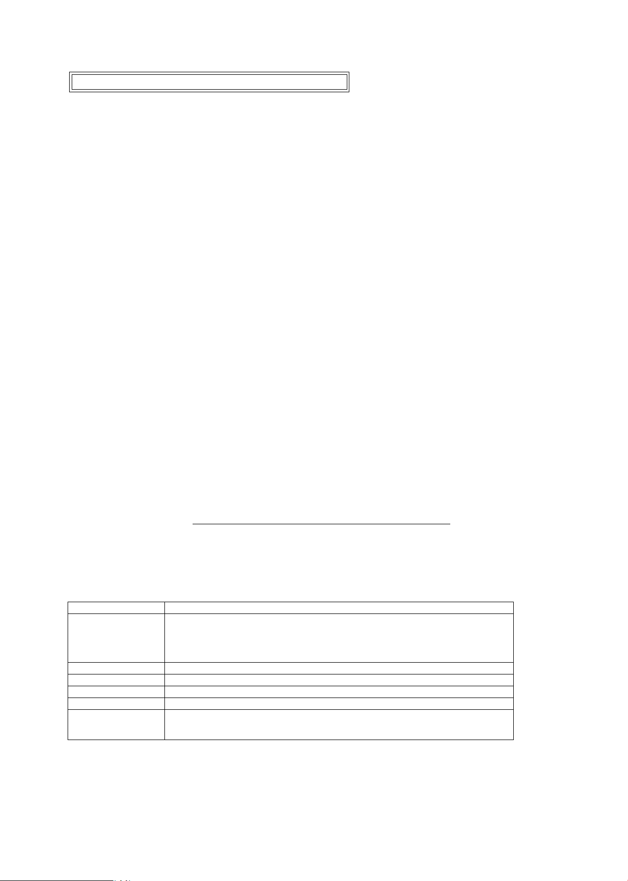
The below hardware requirements are necessary for installing the program on a computer.
Ensure them before installation.
PC IBM PC/AT compatible
OS Windows XP Home Edition, Windows XP Professional, Windows 2000,
Windows Millennium Edition (Me), Windows 98 Second Edition (SE),
Windows 98,
CPU Pentium Ⅱ 266MHz ~ Pentium Ⅳ 2GHz
RAM (Memory) 32MB or more
HD 6 MB-or-more free space is necessary when installation
Monitor resolution 800×600 or more pixels
Interface Serial interface
※ USB interface cannot be used.
As long as the above requirements are met, either desktop or notebook PC is available.
Preparation for inspection & adjustment of main PCB
● In case of replacing the main PCB, SWM unit or MR encoder unit, be sure to make the necessary
adjustments as follows:
1. Adjustments
・Adjust the MR duty
・Adjust the driving frequency and motor control (including Focus preset adjustment)
2. Equipment and tools to be required
・Single output rated voltage power supply: 1 unit ( 6.0V 3.0A)
・Oscilloscope: 1 unit For adjusting the MR duty, the driving frequency and motor control
・AF-I communication box (J15306-1): 1 unit
・AF-I communication adapter (J15307): 1 unit
● When the main PCB is replaced, be sure to perform “3. READING AND REWRITING OF EEPROM
DATA” then “3. WRITING OF THE FIXED VALUES”.
Page 35
JAA79201-R.3669.A
- A20・AF-S 18-55/3.5-5.6G -
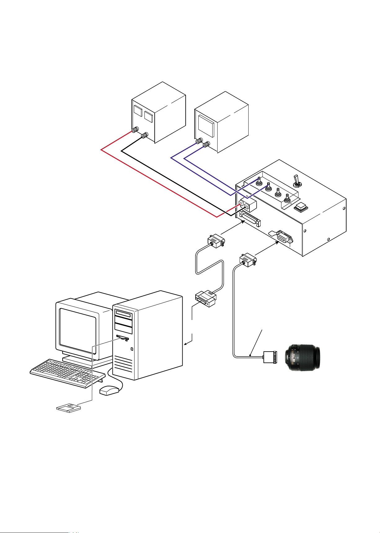
AF-S 18-55
Inspection and adjustment software (J18387)
AF-S lens
(+)
(-)
【System conguration】
When the RS232C terminal of the personal computer
is a 9-pin type, connect it by using the 25-pin/9-pin
conversion connector. RJ does not supply this
connector. Use products on the market.
Personal computer:
This system does not depend on the
CPU type of personal computer.
AF-I communication adapter
(J15307)
To RS232C
terminal
AF-I communication box
(J15306-1)
Oscilloscope
Power supply
(6V)
Page 36
JAA79201-R.3669.A
- A21・AF-S 18-55/3.5-5.6G -
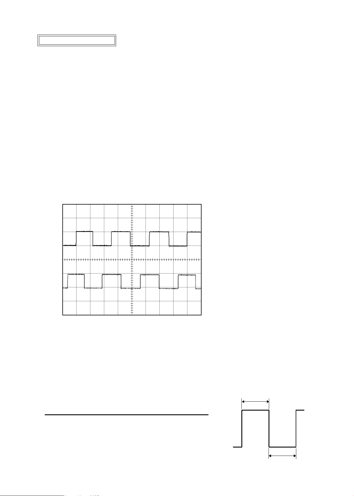
C H 1 = 5 V C H 2 = 5 V 5 m s / d i v
D C 1 0 : 1 D C 1 0 :1
NO R M 20 0 KS /s
H
L
Standard
H:L=
100
:150 ~ 150:
100(50%±10.0
%)
Adjustment of MR duty
●In case of replacing the main PCB, SWM unit and MR encoder unit, be sure to make adjustments.
●In case of replacing the main PCB, be sure to perform [READING AND REWRITING OF EEPROM
DATA.] then [3.WRITING THE FIXED VALUES.]
How to adjust
① Make sure that the electric current and voltage of the connected rated voltage power supply are set to the
set values, which are instructed on the PC screen. Then, turn the rated voltage power supply ON.
② Select "1. MR DUTY ADJUSTMENT" in the menu of the AF-S 18-55 inspection program.
③ The conrmation screen for writing the xed values in EEPROM appears. Select the appropriate item.
④ Following the instruction on the screen, rotate the MF ring slowly by hand in the direction from the innity
to the close distance position. Make sure that the waveform on the oscilloscope has duty 50% and stop the
MF ring at the close distance-end.
● Setting of oscilloscope
V/Div(CH1)
:
5V
V/Div(CH2)
:
5V
Coupling
:
DC
Time/Div
:
5 m Sec
Trigger Mode
:
NORMAL
Trigger Coupling
:
DC
Trigger Source
:CH1
Trigger Position
:
+4 div
Trigger Type
:
EDGE
Trigger Level
:
2.5 V
⑤ Following the instruction on the screen, rotate the MF ring slowly by hand in the direction from the close
distance to the innity position. Make sure that the waveform on the oscilloscope has duty 50% and stop
the MF ring at the innity-end.
Note
:In case the waveform from innity to close distance position or vice versa does not have duty 50%,
repeat "INSPECTION AND ADJUSTMENT OF THE MR ENCODER OUTPUT WAVEFORM" on
Page A5.
Page 37
JAA79201-R.3669.A
- A22・AF-S 18-55/3.5-5.6G -
⑤
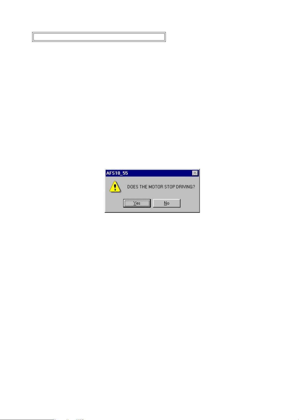
When the above Fig.1 is displayed, if the motor driving stops, select "Yes" to complete the adjustment.
In case the motor does not stop driving, select "No " to make adjustments again.
In case the motor does not stop driving even after the readjustments, adjust the MR duty again and repeat
"ADJUSTMENT FOR DRIVING FREQUENCY & MOTOR CONTROL".
If the adjustment is not successful in spite of the above, the SWM unit, x-tube unit, or MR head unit
may be defective.
Fig.1
Adjustment of Driving frequency and Motor control
● In case of replacing the main PCB, SWM unit and MR encoder unit, be sure to make adjustments.
① The method of connection of the rated voltage power supply and measuring tools is the same as
"ADJUSTMENT OF MR DUTY".
② Make sure that the electric current and voltage of the rated voltage power supply are set to the set values
on the PC screen.
③ Turn the rated voltage power supply ON.
④ Select "2. ADJUSTMENT FOR DRIVING FREQUENCY & MOTOR CONTROL" in the menu of the
AF-S DX18-55 inspection program. The lens automatically starts the driving of scanning.
Page 38

JAA79201-R.3669.A
- A23・AF-S 18-55/3.5-5.6G -
Inspection of Lens operations
Check the lens operations by using a personal computer after assembling.
○ Check by personal computer
● Check by the following considerations:
1.
MR encoder operations
・
Drive the scanning
of lens and check the total number of pulses.
・In case the MR head of the MR encoder and the magnetic tape are misaligned, the number of pulses
becomes out of standard.
2.
Lens-servo stop accuracy
・Check the number of overrun/underrun pulses (deviation of the stop position from the target position) per
the specied lens driving.
・In case the irregularity of mechanical operations does not take place in the focus ring driving unit, the
underrun tends to occur if it is heavy in the cam ring rotation of the MR encoder, while the overrun tends
to occur if it is light in its rotation of the MR encoder.
3.
Lens-servo time
・Check the servo time (from starting and stopping the servo) when driving the specied lens by using the
oscilloscope.
・In case the irregularity of mechanical operations does not take place in the focus ring driving unit, the
servo-time tends to be long if it is heavy in the cam ring rotation of the MR encoder, while the servo-time
tends to be short if it is light in its rotation of the MR encoder.
4.
Switches and lenses
・Check the ON/OFF operations of switches and the operating condition of the distance encoder.
● After inspections
1. When the MR encoder operations are not up to the standard:
Readjust the MR duty. (ref. Page A26.)
In case the pulse is not up to the standard, adjust the output waveform of the MR encoder again.
(ref. Page A5.)
In case the pulse meets the standard, replace the cam ring unit.
2. When the lens-servo stop accuracy is not up to the standard:
Check the output waveform of the MR encoder. If it is normal, replace the x-tube unit.
3. When the lens-servo time is not up to the standard:
Readjust the driving frequency and motor control.
In case the lens-servo time is not up to the standard even after the readjustment, replace the x-tube
unit.
4. When switches do not work properly:
Check the wiring state of the troubled switch or replace it.
Page 39
JAA79201-R.3669.A
- A24・AF-S 18-55/3.5-5.6G -
1
2
3
4
5
6
7
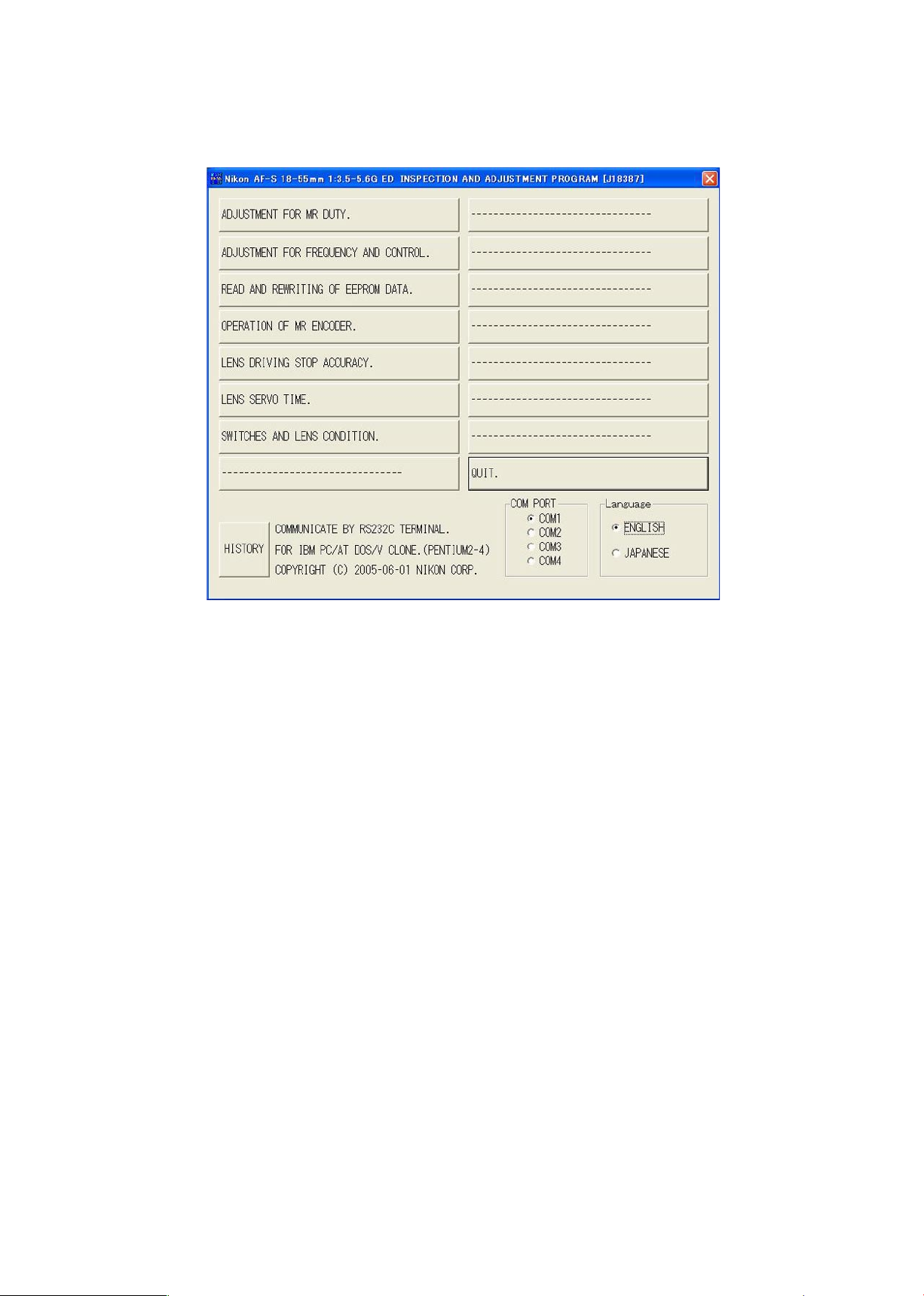
●AF-S DX18-55 inspection program
(1)
Menu screen
・Menu items
The items 1 and 2 are used for adjustments.
The item 3 is used for reading and writing EEPROM DATA.
The items 4~7 are used for inspections.
・Selection items
After selecting items screens appear, such as the lens selection, the
focal length selection, the voltage setting, the inspection mode start.
The screens depend on the items. Follow the instructionsof the personal computer.
・Initial driving
Drive scanning several times and stop at innity-end.
Page 40

JAA79201-R.3669.A
- A25・AF-S 18-55/3.5-5.6G -
<<<
EXECUTING
>>>
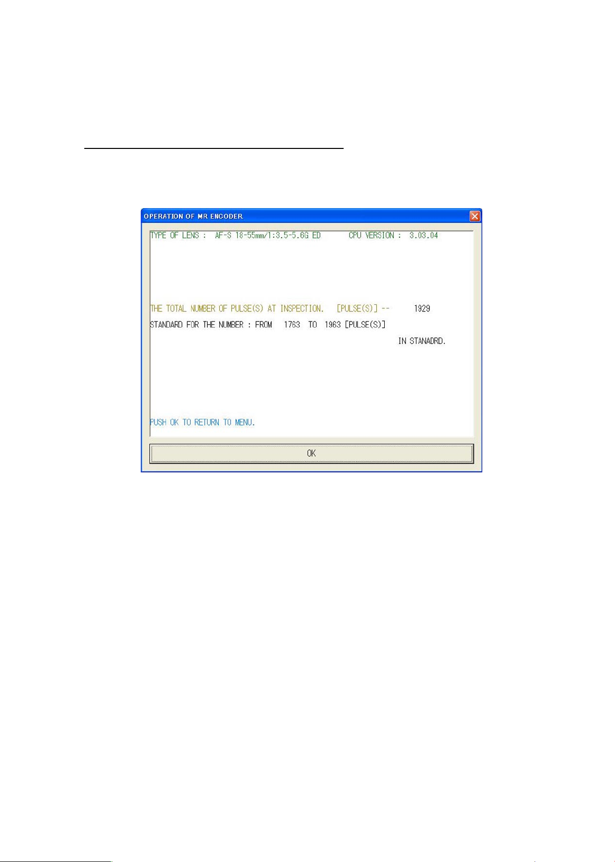
(2)Inspection of MR encoder operations
Caution:If the MF ring is rotated while the lens scanning is driven, the pulse shows an abnormal value.
Do NOT touch the MF ring during operations.
Make inspections at the 5 positions as below.
When the inspection ends, the result of the next page appears.
Page 41
JAA79201-R.3669.A
- A26・AF-S 18-55/3.5-5.6G -
The difference in pulse before and after the inspection must be within the standard.
<
Standard > Total pulses :
1863 ± 100 PULSE(S)
Page 42
JAA79201-R.3669.A
- A27・AF-S 18-55/3.5-5.6G -
①
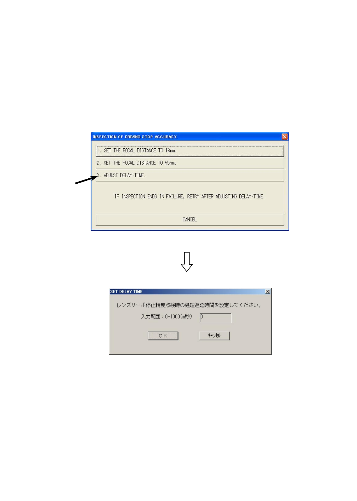
Make this inspection on both focal length 18mm (W) and 55mm (T).
②
If the lens stops while inspecting the lens-servo stop accuracy, select "3. ADJUST DELAY-TIME" of
the below Fig.2, and input a gure between 0-1000 for the delay time (msec: millisecond) which pre-
vents stopping the lens.
Fig.2
(3)
Inspection of lens-servo stop accuracy
Note:
The value of "ADUST DELAY-TIME" is set by the adjustment software. So, if the lens does not
stop during the inspection of "LENS DRIVING STOP ACCURACY", any value can be input without
problem.
However, the larger the value of "ADJUST DELAY-TIME" gets, the longer the inspection time becomes.
Page 43
JAA79201-R.3669.A
- A28・AF-S 18-55/3.5-5.6G -
①
④
⑤
②
③
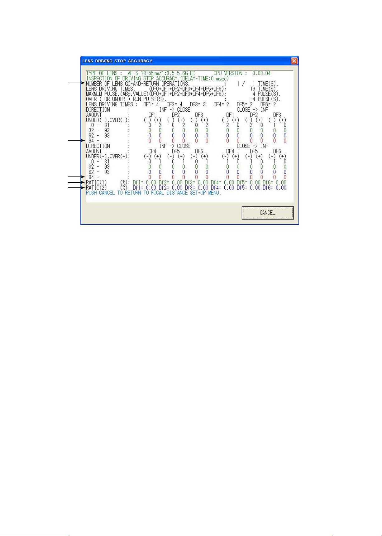
Caution:If the MF ring is rotated while the lens scanning is driven, the pulse shows an abnormal value. Do
NOT touch the MF ring during operations.
During the lens driving, the above screen is displayed.
The number of overrun/underrun pulses must be within the standards after the lens back-and forth driving
5-motion ("1/1TIME (S)." in [1] of the display).
Standard RATIO (1) is 40% or less for Df1~Df6.
② of the screen
[Occurrence ratio of (W) 32-93/(T) 7-18 pulses]
RATIO (2) is 20% or less for Df1~Df6.
③ of the screen
[Occurrence ratio of (W) 62-93/(T) 12-18 pulses]
Occurrence of (W) 94/(T) 19 or more pulses is zero for Df1~Df6.
④ and ⑤ of the screen
[Only one occurrence indicates defective.]
※ "Df1~Df6" shows the lens driving amount.
Page 44
JAA79201-R.3669.A
- A29・AF-S 18-55/3.5-5.6G -
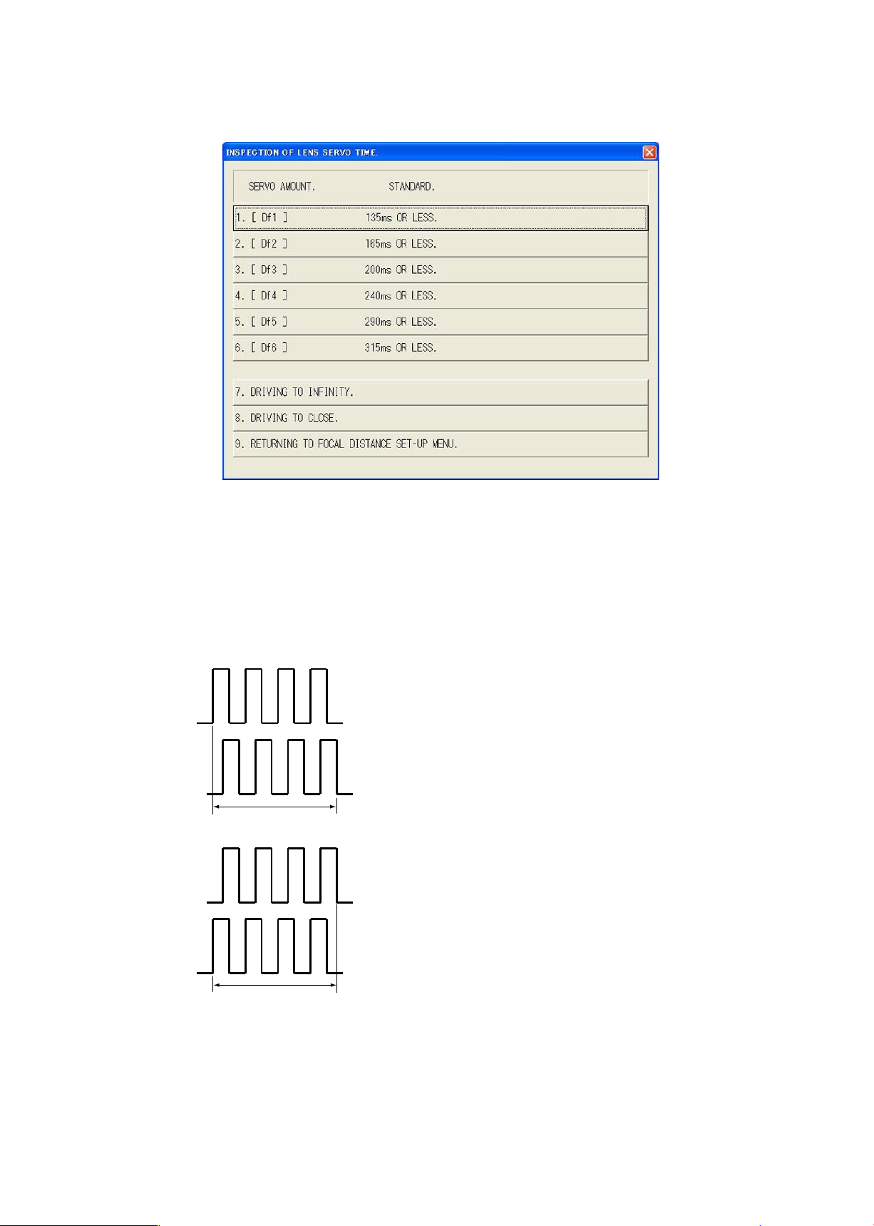
(4)
Inspection of lens-servo time
Make this inspection on both focal length 18mm (W) and 55mm (T).
Connect the probes of oscilloscope to E and H terminals of the AF-I communication box (J15306). Select the
servodriving amount respectively. Each lens-servo drive time must be within the standard.
Caution:If the MF ring is rotated during inspections, the waveform shows an abnormal value. Do NOT touch
the MF ring during inspections.
E terminal
H terminal
E terminal
H terminal
Servo driving time
Servo driving time
●Oscilloscope setting
V/Div
:
5V
Coupling
:
DC
Time/Div
:
20 m Sec
Trigger Mode
:
SGL (S)
Trigger Coupling
:
DC
Trigger Source
:
CH1
※ The waveforms of E and H terminals have the
forms for going up for start and going down for
start.
Page 45
JAA79201-R.3669.A
- A30・AF-S 18-55/3.5-5.6G -
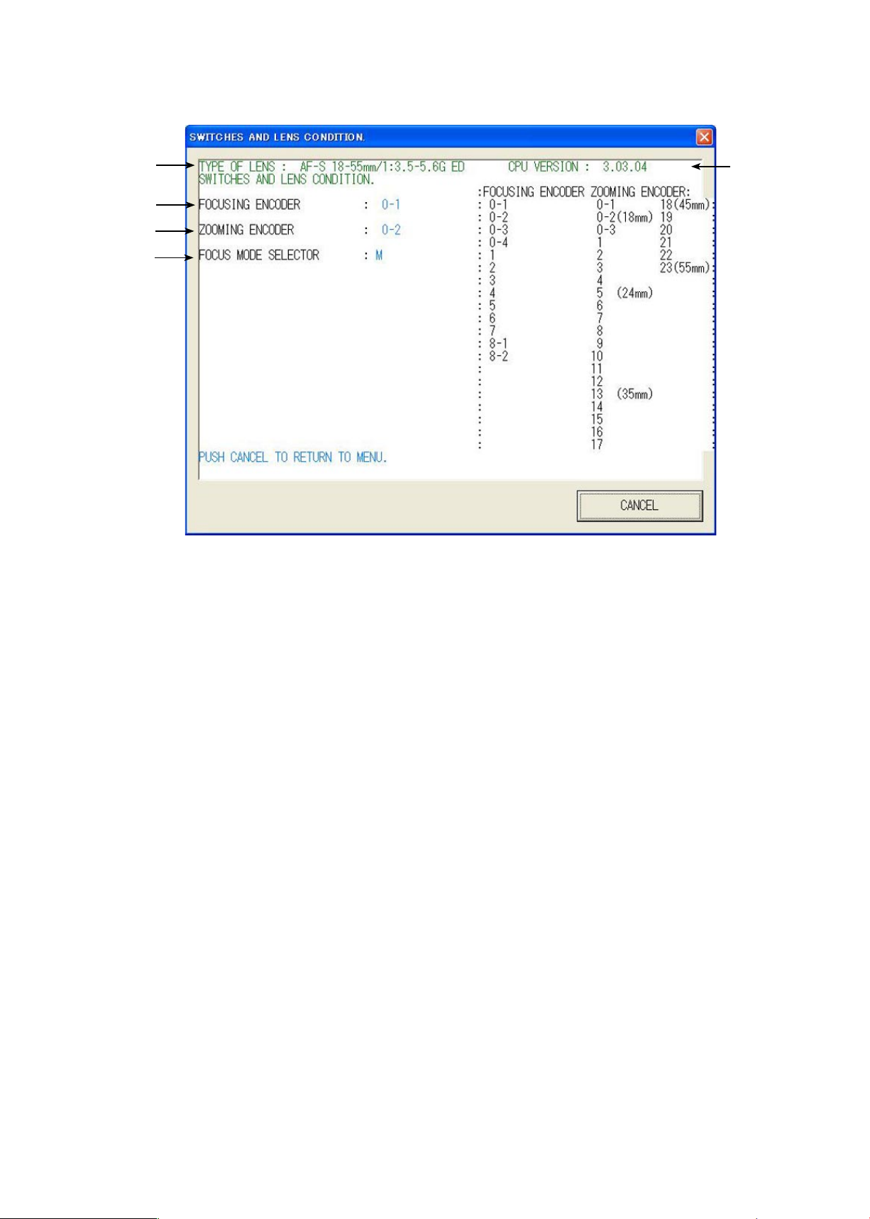
①
③
④
⑤
②
① Type of lens
② Version of CPU in the lens
③ Signals of the distance encoder
Value changes by turning the MF ring with “M” or M/A of the lens driving mode selector.
④
Position of the zoom encoder
(Value changes by turning the
zoom ring)
⑤ lens driving mode selector SW
(5)
Inspection of
switches and lens conditions
Page 46
JAA79201-R.3669.A
- A31・AF-S 18-55/3.5-5.6G -
Adjustment for MR duty
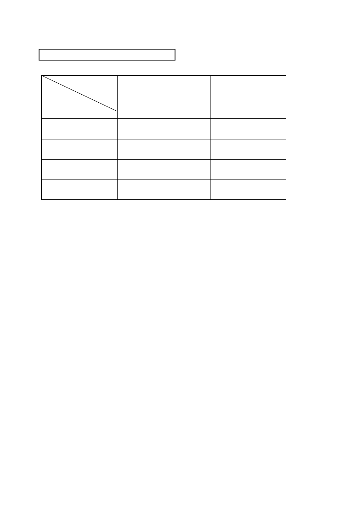
(Necessary to write xed value);
driving frequency; motor control
Inspection & adjustment for MR
encoder operations;
lens-servo stop accuracy;
lens-servo time; switches;
lens condition
Main PCB unit
○ ○
SWM unit
○ ○
MR head unit
○ ○
Fixed tube unit
○ ○
Necessary adjustment when replacing parts
Parts to be
replaced
Adjustments
Page 47
JAA79201-R.3669.A
- A32 ・ AF-S 18-55/3.5-5.6G -
Aberration compensation data writing adjustment
・
This adjustment uses the software which calculates the aberration compensation data according to the feature
of lens aberration and writes in EEPROM of the lens, in order to improve the accuracy of autofocus.
Note: This adjustment is necessary when the main PCB and/or each lens part (glass, lens chamber) is
replaced or when each lens part is disassembled. Be sure to make this adjustment after completing
inspecting and adjusting the main PCB.
(1) Preparation
・
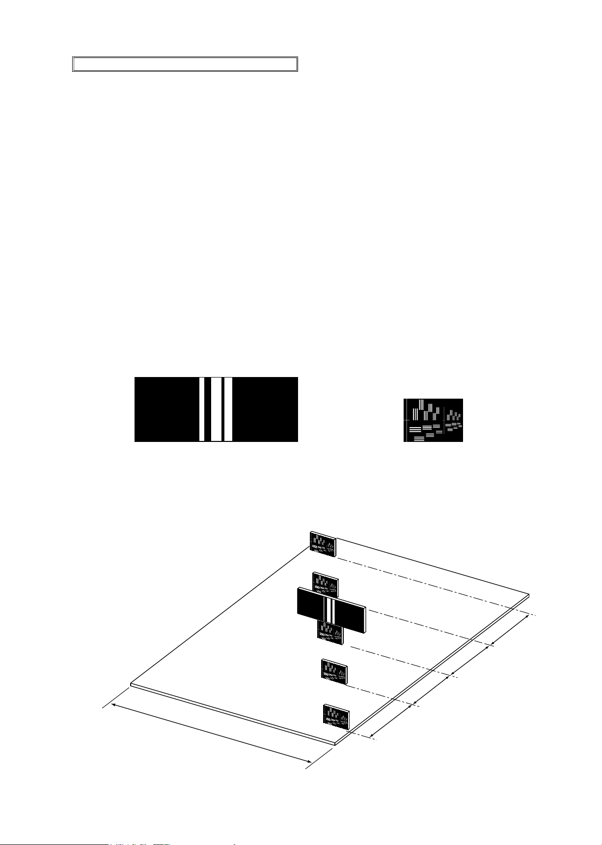
Test chart (Self-made tool: ref. Procedure for how to create it.)
・
Tripod
・
D100
・
Personal computer
・
USB cable(UC-E4
)
・
Adjustment software (LWM.exe:used for the lens optical alignment.)
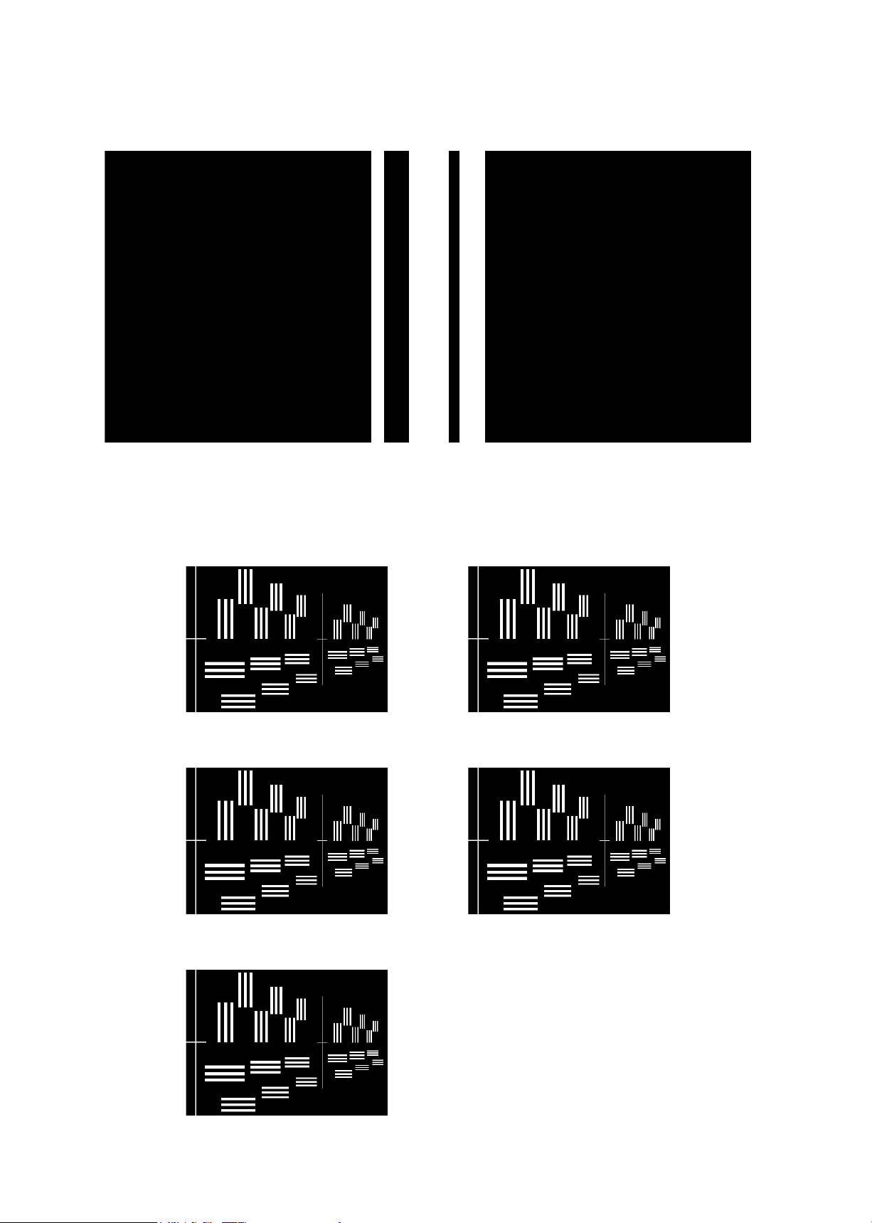
(2) Procedure for how to create Test chart
・
Photocopy the next page and cut out 1 target chart and 5 resolution charts.
(
Target chart
)
(
Resolution chart
)
・
As shown below, put each chart in position at the specied spacings.
Note: Only in the center, put the target chart on the central resolution chart.
300mm
45mm
45mm
45mm
45mm
(+100μm)
(-100μm)
(-50μm)
(0μm)
(+50μm)
Page 48
JAA79201-R.3669.A
- A33 ・ AF-S 18-55/3.5-5.6G -
(
Target chart
)
(
Resolution chart
)
Page 49
JAA79201-R.3669.A
- A34 ・ AF-S 18-55/3.5-5.6G -
(3) Writing aberration compensation data
① Prepare a camera (D100). Set the "Exposure mode" to "A" for full aperture and "Focus mode" to "S".
On the shooting menu, set the "Image quality mode" to "FINE", "Image size" to"L", "WB" to "Preset", and
"ISO" to "200".
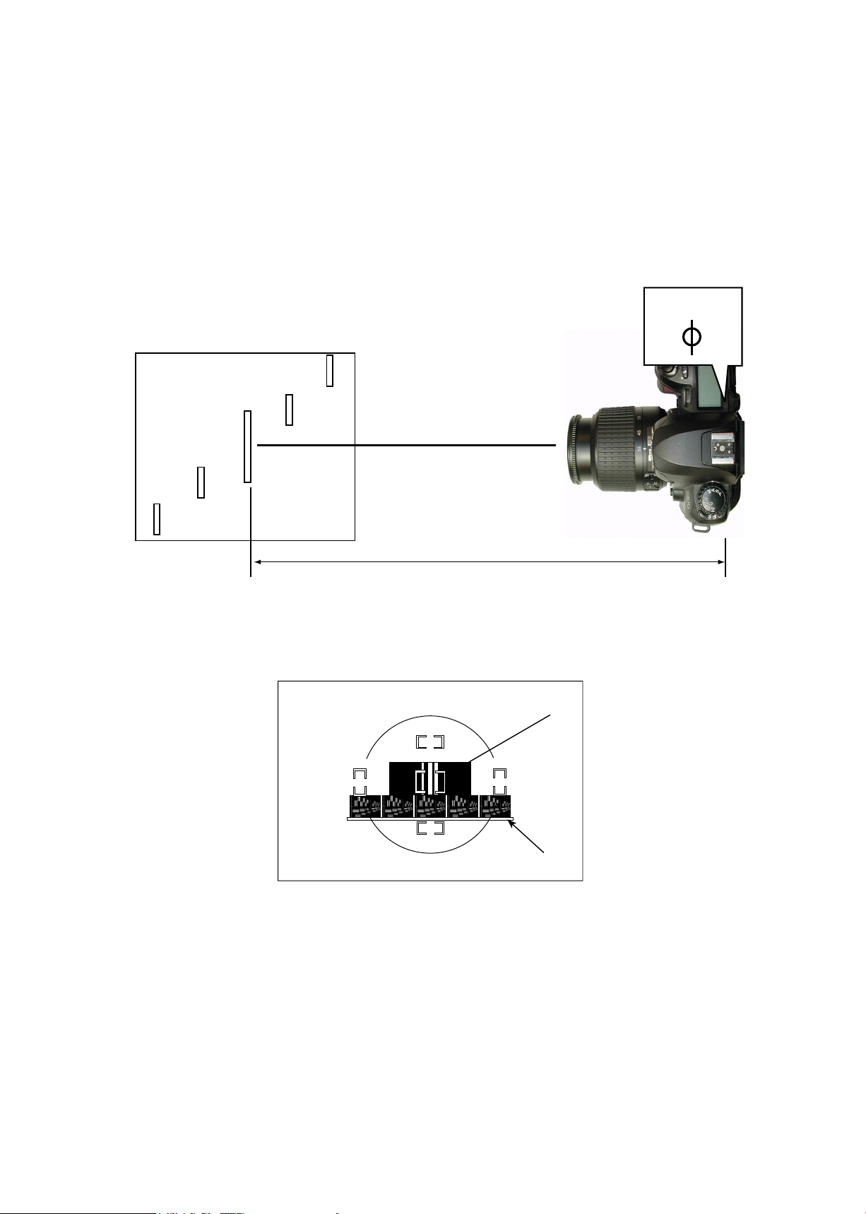
② Set up the camera (D100), in which the lens to be inspected is t, on the tripod
. Set the focal length to
55 mm, and the distance between the test chart and camera (CCD face) to 2 m 20±2 cm.
2 m 20±2 cm
(CCD-face position)
(
Test chart
)
③
As shown below, bring the target chart in the center of focus area within viewnder.
Target chart
(
Within viewnder
)
Resolution chart
④ Connect the PC and camera via USB cable.
(Camera setting: Mass storage)
⑤ Start the adjustment software (LWM.exe).
Page 50
JAA79201-R.3669.A
- A35 ・ AF-S 18-55/3.5-5.6G -
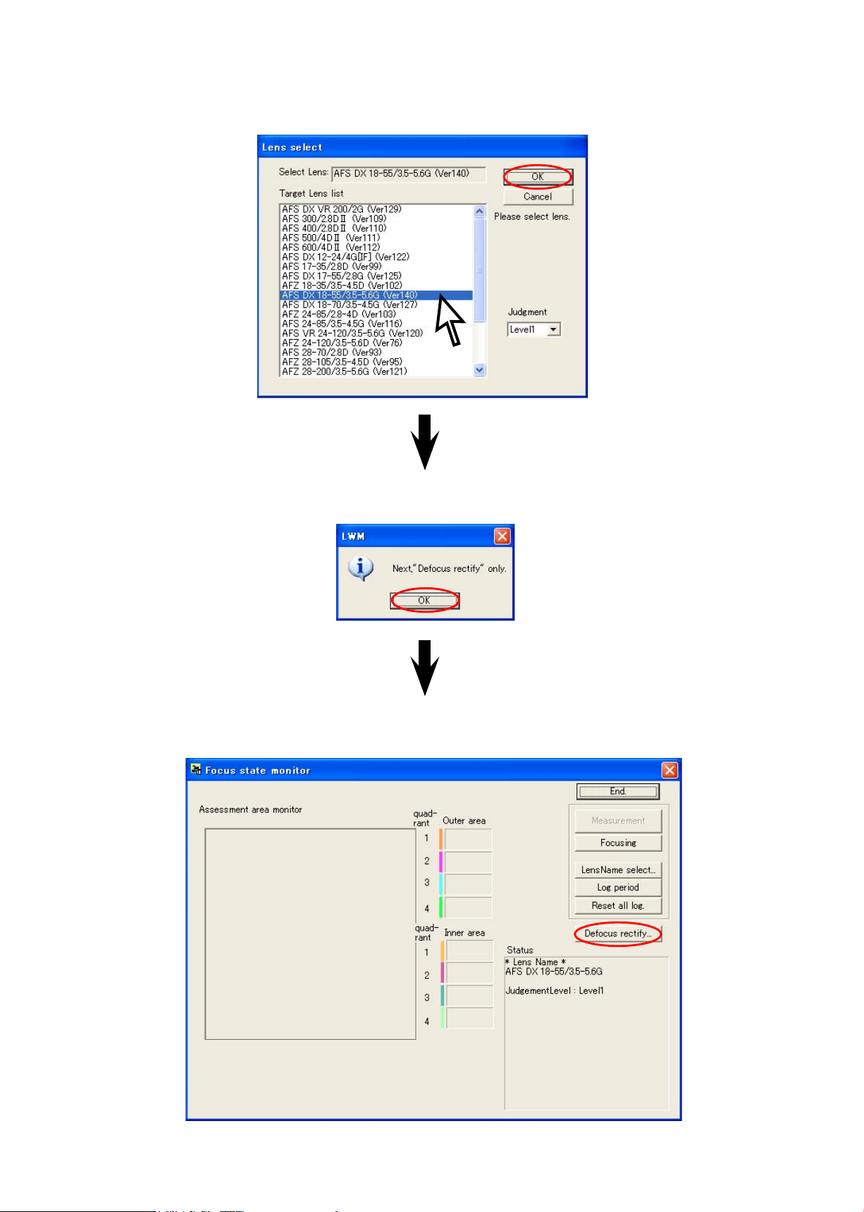
⑥
Select "AF-S DX18-55/3.5-5.6G" from "Target lens list", and click "OK" button.
⑧ Click the "Defocus rectify..." button.
⑦
When "Next, Defocus rectify only" window appears, click "OK" button.
Page 51
JAA79201-R.3669.A
- A36 ・ AF-S 18-55/3.5-5.6G -
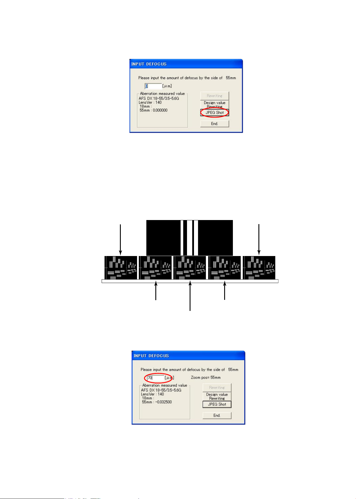
⑨ Click the "JPEG Shot" button.
⑩ The shutter is released after the AF operation. The shot image is automatically displayed on the PC screen.
Scale the image to 100% and check which chart is in focus of the 5 resolution charts.
Note: As for this lens, even if the aperture is fully open, the depth of eld is so deep that when looking for
the center of focus, compare 2 charts between which there are 2 or more charts.
(+
100μm
) (-
100μm
)
(+
50μm
) (-
50μm
)
(
0μm
)
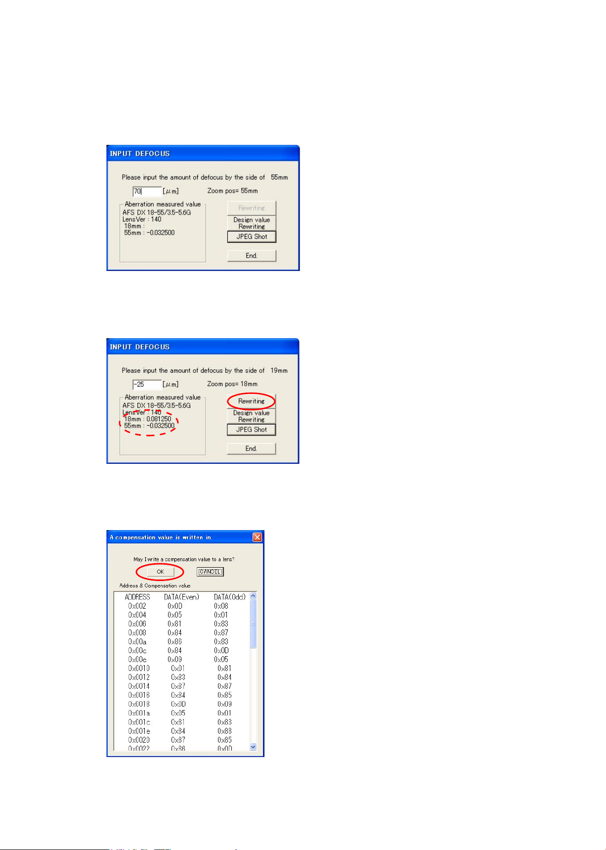
⑪ Input the value of the focused position into the entry eld.
e.g. The below is the case when "+70μm" of the front focus side is in focus.
Page 52
JAA79201-R.3669.A
- A37 ・ AF-S 18-55/3.5-5.6G -
⑭
Check that the values of all the focal lengths
are displayed within the dotted red circle. Then click on
"Rewriting".
⑮ When "
A compensation value is written in." is displayed, click "OK".
⑫
Set the focal length of the lens to 18 mm, and the distance between the test chart and
camera (CCD face)
to
72±2 cm.
⑬ Perform the operations from ⑨
to ⑪of the previous page.
Page 53
JAA79201-R.3669.A
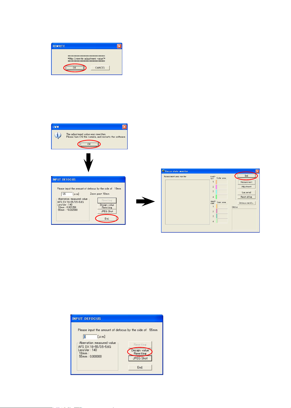
- A38 ・ AF-S 18-55/3.5-5.6G -
⑯ The reconrmation screen is displayed.
Click "OK".
⑰ An hourglass is displayed on the screen, and writing starts.
The below screen is displayed after a few seconds. Turn camera OFF and turn it ON again.
Click "OK", and the adjustment software restarts.
Note: Unless the camera is turned off once, the value that was written in EEPROM is not reected.
⑱
When the adjustment software restarts, perform the operations from ② to ⑬ again. Check that "0μm" of
the AF position is in focus.
(It is also possible, after Wide-side shooting of ⑫, to take the Tele-side shooting of ②.)
If "0μm" is not in focus, repeat the operations from ② to ⑱.
If it is not still in focus even after repetition, the written value in EEPROM may be abnormal. So click
"Design value Rewriting" to write the initial value, then proceed with the operations.
Page 54
JAA79201-R.3669.A
- A39 ・ AF-S DX18-55/3.5-5.6G -
Be sure to make an inspection and adjustment, when dissembling and repairing the lens-barrel.
1. Check the resolution
By shooting the high-denition resolution chart (J63079), conrm that the TV lines are within the standard.
Standard for the TV lines:
1400 or more TV lines in the center ; 1200 or more TV lines on the periphery /4 corners
at both WIDE (18mm) and TELE (55mm)
(ref. The unit of resolution is based on TV lines, which are total number of black-and-white strips
distinguishable on the TV screen.)
Device: D100 camera, ITE high resolution chart (J63079), icker-less uorescent (AAA)
(a) Camera settings: Shooting-mode: Aperture-Priority Auto (A), Aperture: Full, Image quality mode
(FINE), Image size (FULL), ISO (200), Image sharpening (None)
Reset other settings (e.g. compensation) and shoot pictures.
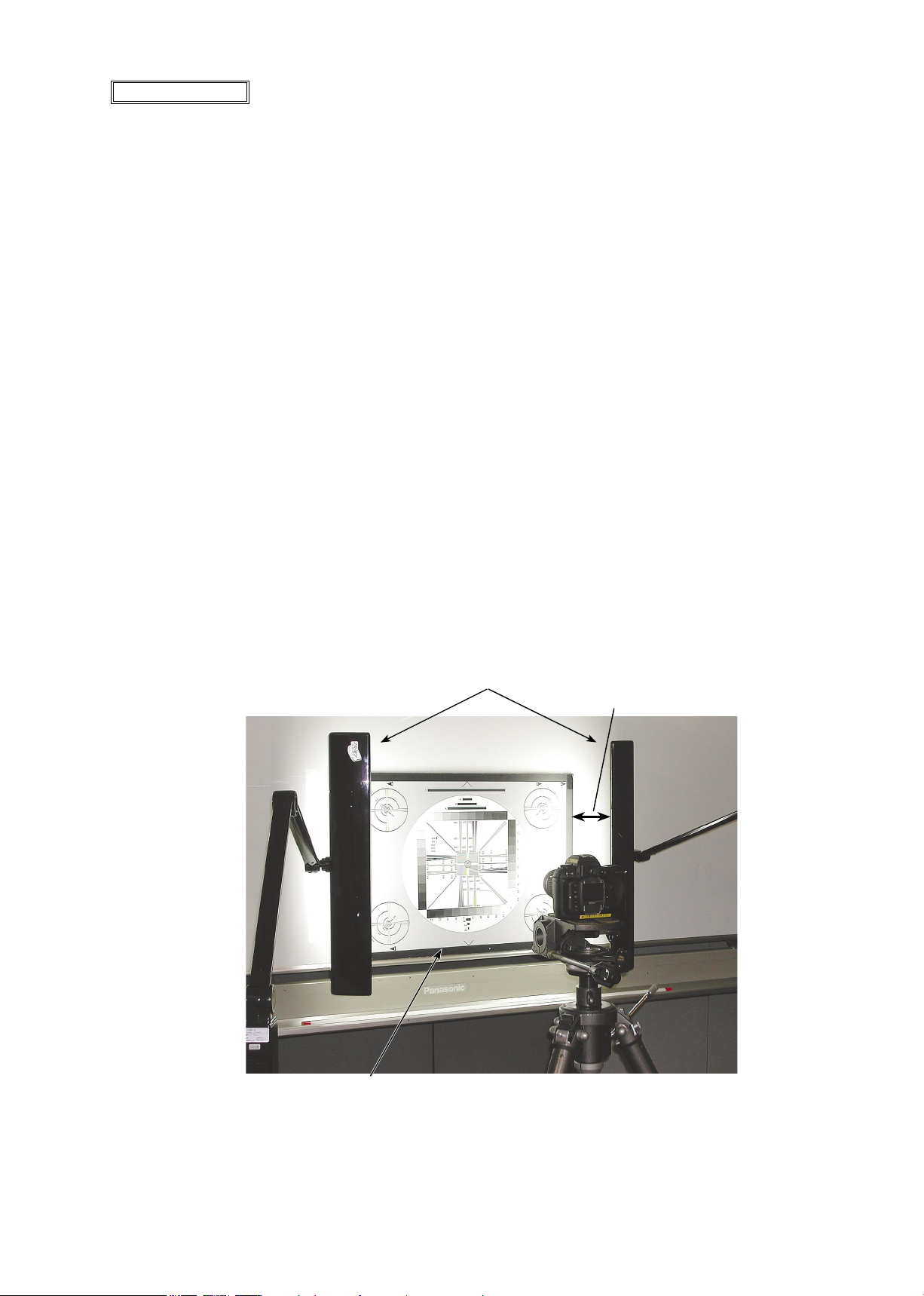
(b) To avoid light irregularity on the chart, for either 2 units of Z light (Z-309)(J19124) or 2 units of 15W
inverter-type uorescent stand, use uorescent lamp color-rendering AAA (J19124A). Set them so that
reected light does not directly come in shot images. (ref. Pic.1)
As for exposure, open the shot images via PHOTOSHOP, and make an exposure compensation so that
the value of RGV becomes 219±10 LSB, when the cursor comes to white parts of the images.
(ref. : Set the exposure compensation to about +1-step for becoming 219±10 LSB.)
Pic.1
Z light Z-309 (J19124)
high-denition resolution
chart (J63079)
30 cm or more
Lens alignment
Page 55
JAA79201-R.3669.A
- A40 ・ AF-S DX18-55/3.5-5.6G -
(c) Check the zoom position at WIDE and TELE.
The object distance: WIDE (approx.0.6m), and TELE (approx.1.5m). Set the chart fully screened in the
LCD of the camera and x it on a tripod.
Because horizontal-to-vertical/aspect ratio is different between the chart and the nder eld frame, align
with the vertical direction (ref. Pic.1)
(d) Open the shot image by Photoshop, and conrm it by the magnied display, e.g. 100%, etc.
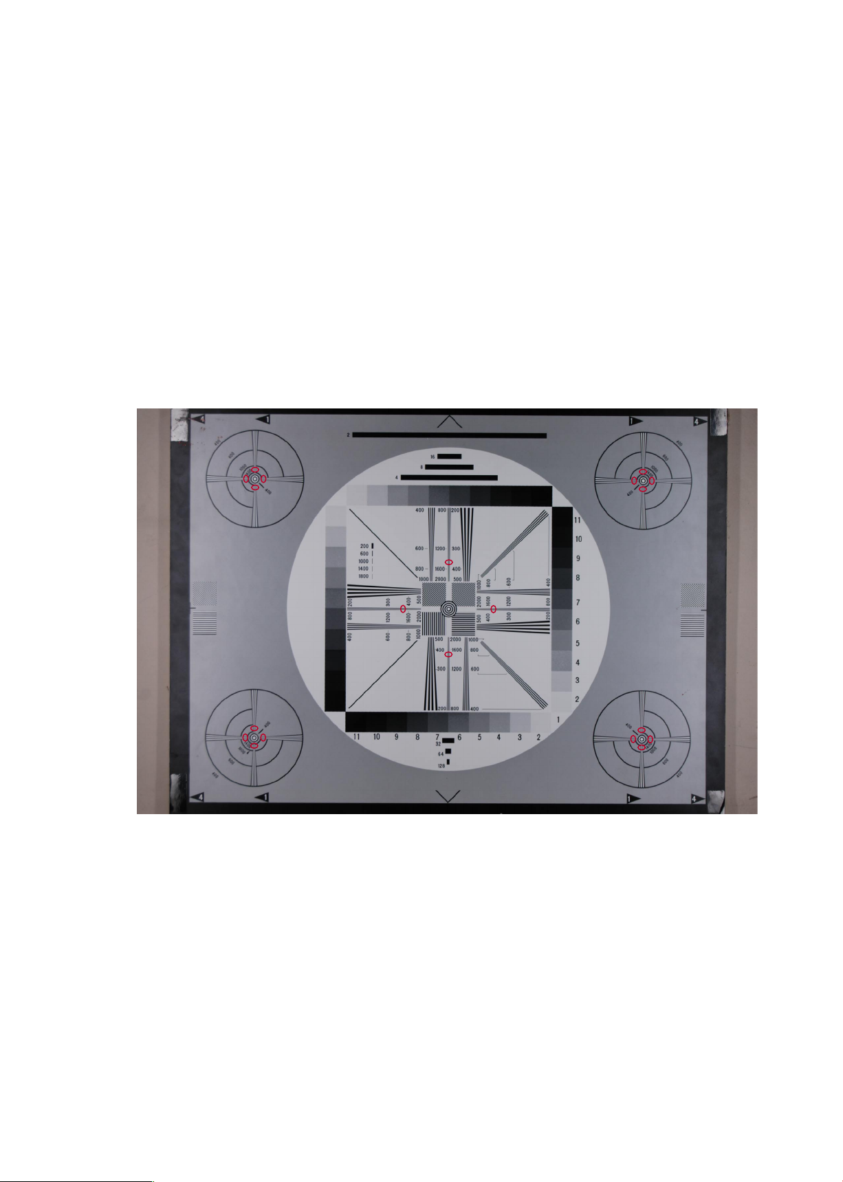
(e) Check if the resolution in the center and the 4 corners is identiable in black and white at the position
circled in red as below.
(Refer to the next page for sample of defective image.)
Pic.1
Page 56
JAA79201-R.3669.A
- A41 ・ AF-S DX18-55/3.5-5.6G -
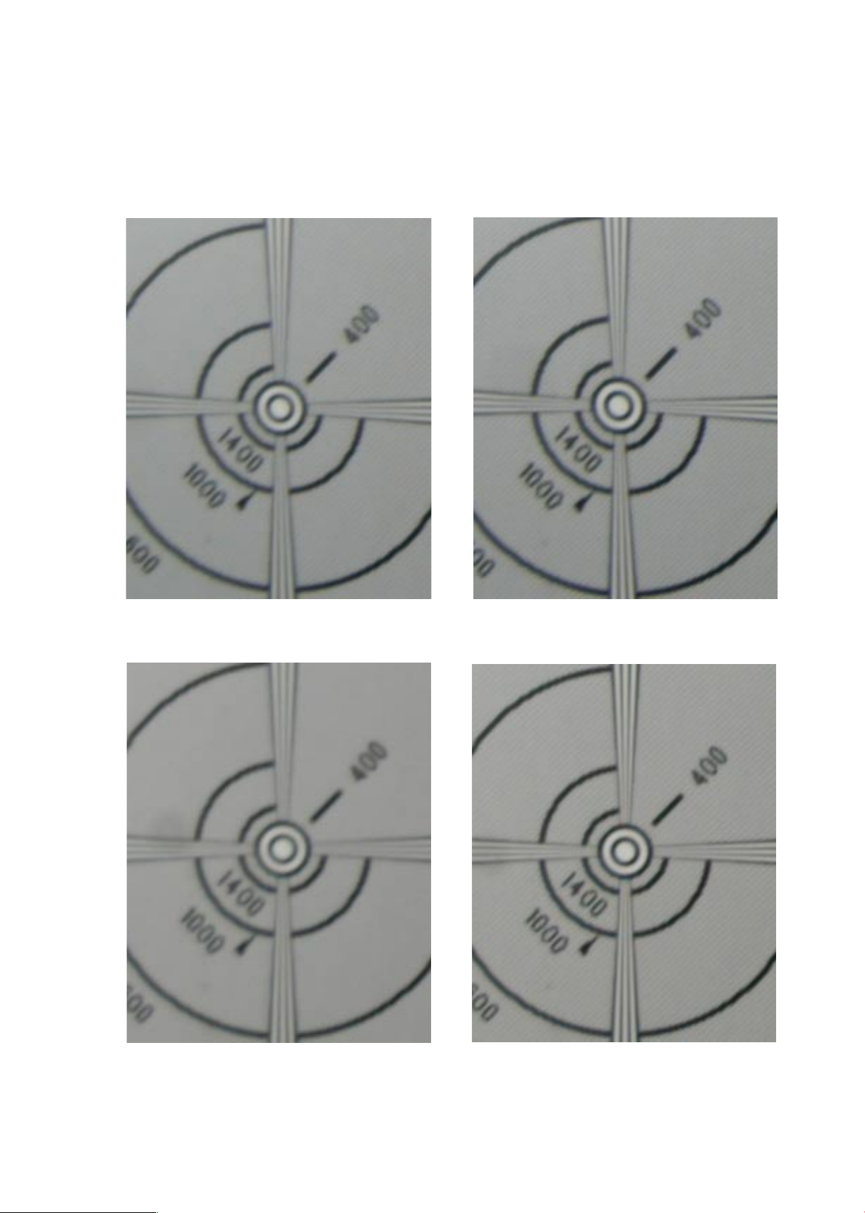
2. Sample image: for judging the chart (on the periphery)
Shoot pictures of the chart. In case TV lines of the center become less than 1400, or any of the periphery/4
corners shows the following image of defective samples (less than 1200 TV lines), make an adjustment on
the next page.
Note: For the judgment, the defective image sample should be prioritized over the number of TVlines.
Defective at WIDE side
NON-defective at WIDE side
Defective at TELE side
NON-defective at TELE side
Page 57
JAA79201-R.3669.A
- A42 ・ AF-S DX18-55/3.5-5.6G -
90°
180°
270°
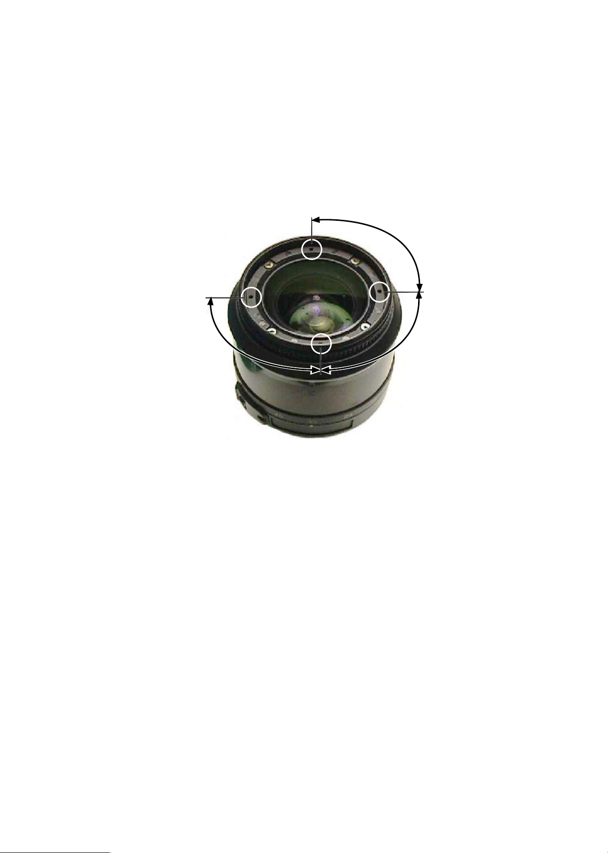
3. Adjustment
In case the result of the resolution inspection becomes out of standard, detach the 1st lens group. Then, turn the
1st lens group through 90° to assemble into the body by using the 1st lens group assembling tool (J11315).
To nd the best adjusted point, check the following: 90°→180°→270°. If all of these 3 points does not become
within standard, some defective parts caused by a damage such as shock should be considered. Therefore,
replace probable faulty parts (e.g. bayonet mount, 1st/2nd lens group, lter ring, xed tube unit, etc) and make
an inspection on resolution again.
Page 58
JAA79201-R.3669.A
- A43 ・ AF-S DX18-55/3.5-5.6G -
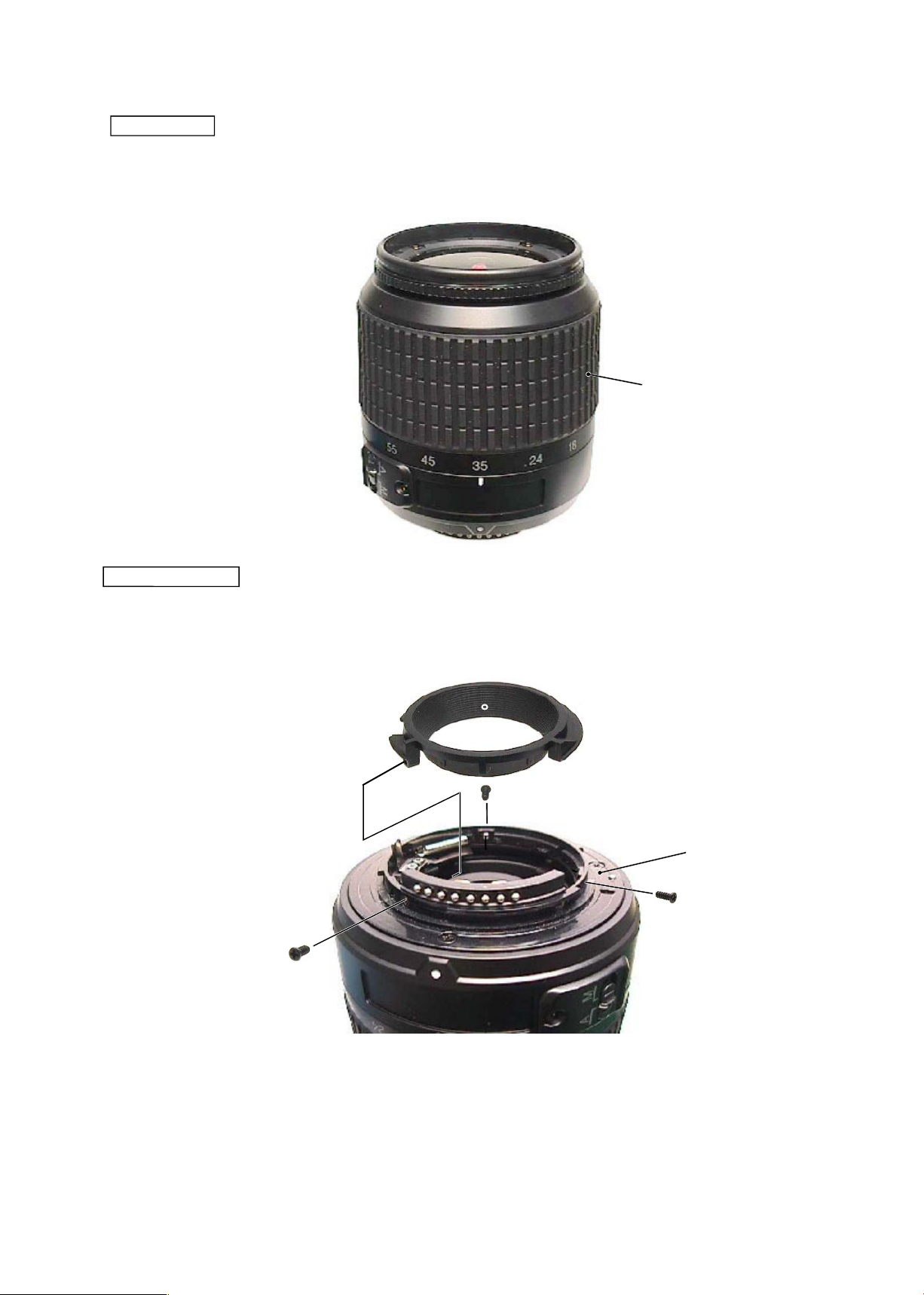
#62
#39
#91×3
#B27
Rubber ring
・
Assemble the rubber ring (#62).
Rear cover ring
・
Set the zoom to TELE side. Assemble the rear cover ring (#39) into the bayonet mount unit (#B27) and x
them with 3 screws (#91).
Page 59
JAA79201-R.3669.A
- A44 ・ AF-S DX18-55/3.5-5.6G -
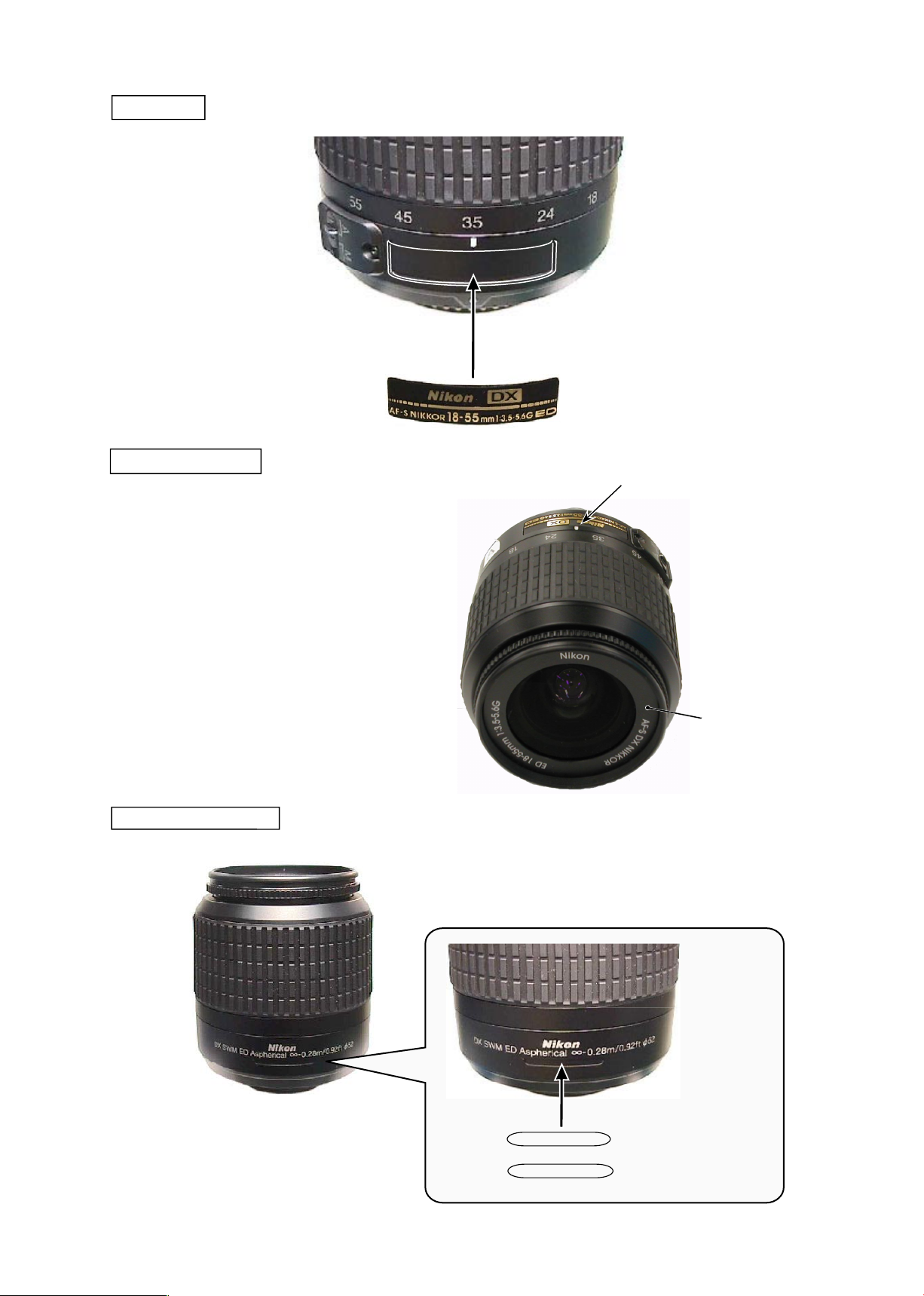
MADE IN THALAND
NIKON CORP JAPAN
#113
Name plate
#68
Company name ring
Index
・
When the focus ring is set to the innity-end,
attach the company name ring (#113) so that
the index position is aligned with "k" letter
of "Nikon" of the ring.
Country of origin seal
#134 (black)
#334 (silver)
#133 (black)
#333 (silver)
Page 60
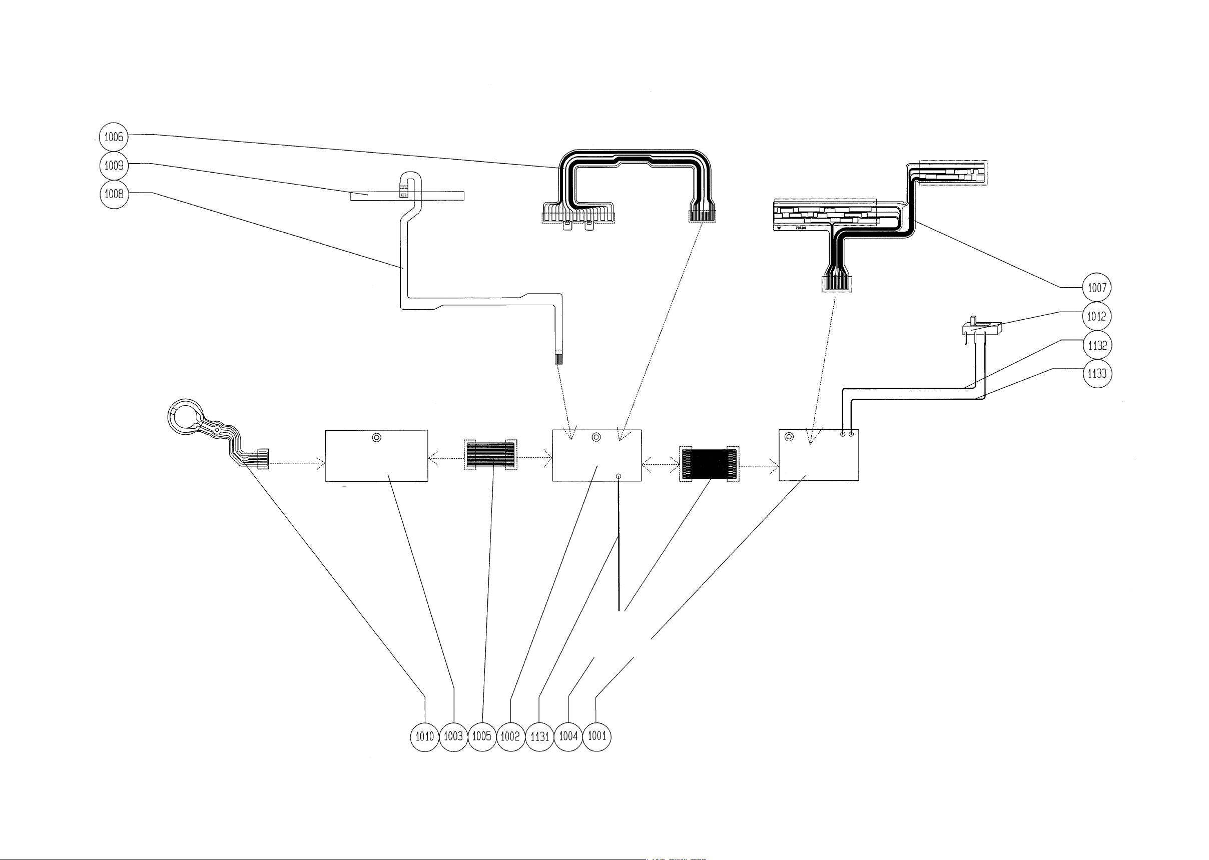
- E 1・AF-S DX 18-55/3.5-5.6G -
JAA7951-R.3669.A
鏡体 GND へ
To Lens unit
GND
実体配線図
WIRING DIAGRAM
白
White
CPU 基板
CPU PCB
C
N 接続(表面)
Connected with
CN (Face side)
モーター駆動基板
Motor drive PCB
C
N 接続(表面)
Connected with
CN (Face side)
C
N 接続(裏面)
Co n n ected w i th CN
(Reverse side)
C
N 接続(裏面)
Co n n ected w i th CN
(Reverse side)
赤 Red
黒 Black
はんだで接続
Connected with soldering
中継 FPC B
中継 FPC A
MA8A 基板
MA8A PCB
Connection FPC B
Connection FPC A
CN 接続(表面)
CN Connecting
(Face side)
MR センサー付き FPC
MR Sensor FPC
C
N 接続(表面)
Connected with
CN (Face side)
C
N 接続(表面)
Connected with
CN (Face side)
To the contacts
接点部材へ
接点FPC
Contact FPC
絶対距離 FPC
Absolute focal
distance FPC
ズーム FPC
Zoom FPC
MR Magnetic tape
MR 磁気テープ
SWM-FPC
(To unit SWM)
(SWM 部組へ)
C
N 接続(裏面)
Co n n ected w i th CN
(Reverse side)
M/A SW
M/A スイッチ
Page 61
JAA79251-R.3669.A
- F1
・ AF-S DX 18-55/3.5-5.6G
-
外観図 Sketch drawings
Page 62
JAA79251-R.3669.A
- F2
・ AF-S DX 18-55/3.5-5.6G
-
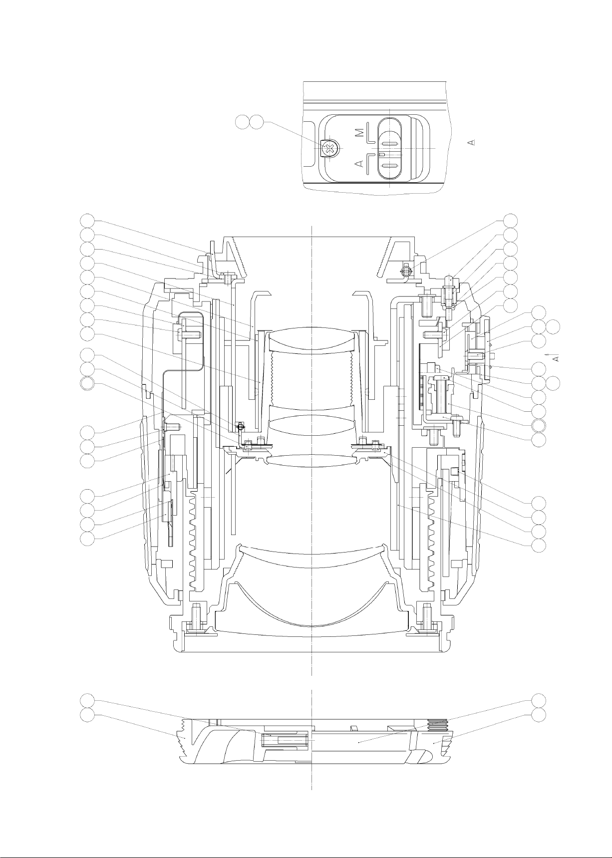
組立図 Structure of the Lens
181
183
142 59 47
95
29
501
132 131 152
352
153
154 151
1012
351
1003
89
89
123
122 121 84
23
93
99
5546148
1002
89
4571335
1003
7975
26
44
1009
41
182 184
355
155
Page 63
JAA79201-R.3669.A
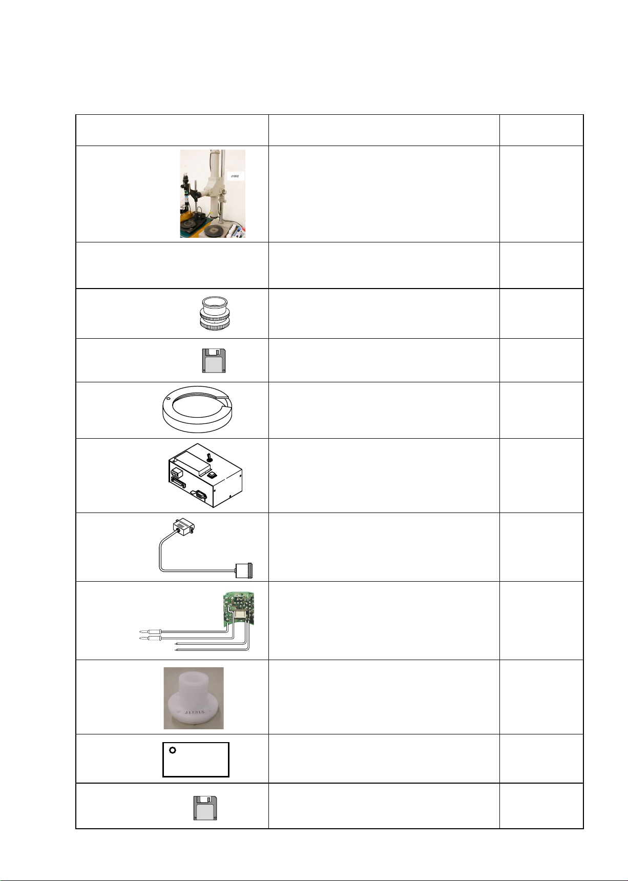
- T1 ・ AF-S DX18-55/3.5-5.6G -
RJ 番号
RJ No.
名称
NAME OF TOOL
備考
OTHERS
J19002
縦型焦点面検査器 LT-500S
BACK FOCUS COLLIMATER LT-500S
J9001-5N
安定化電源5A
DC REGULATED POWER SUPPLY 5A
J18028
F用レンズ受け台
LENS ADAPTER FOR FOCUS TESTER
J18387
AF-S DX 18-55 点検・調整ソフト
ADJ.FD FOR AF-S 300VR (IBM 3.5)
J18004-1 J18004用基準ゲージ
STANDARD GAUGE FOR J18004
J15306-1
AF-I通信ボックス
AF-I LENS COMMUNICATION BOX(CE)
J15307
AF-I通信アダプター
COMMUNICATION ADAPTER FOR AF-I
自作工具 自作工具
SELF-MADE TOOL
FOR AF-S24-85
J11315
1群組立工具
1ST LENS G ASSEMBLING TOOL
J11316
Z ブラシ挿入用シート
Z BRUSH INSERTION SHEET
J18379
調芯装置用調整ソフト(LWM)
ADJ.FD (LWM)FOR LENS ALIGNMENT
工具編
TOOLS
★:
NEW TOOL
★
★
★
Page 64
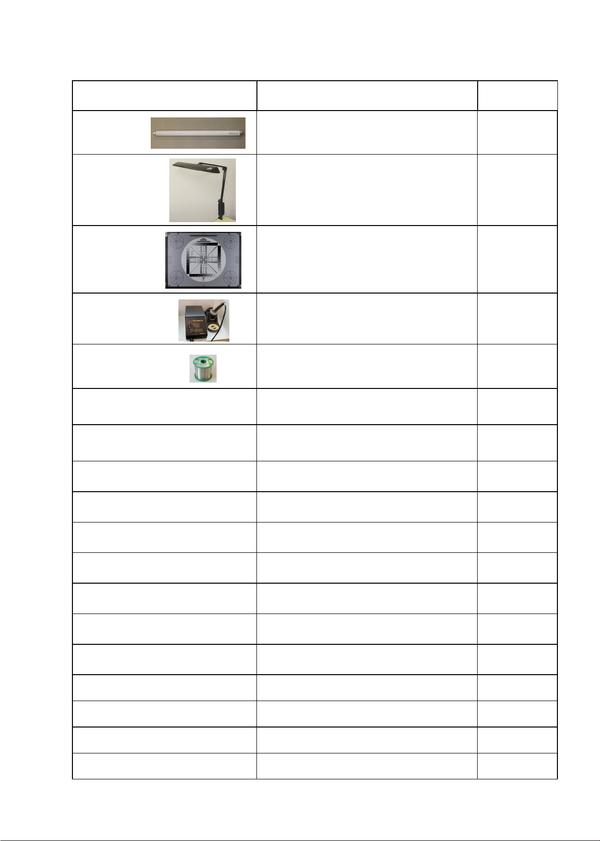
JAA79201-R.3669.A
- T2 ・ AF-S DX18-55/3.5-5.6G -
J19124A
蛍光ランプ FL15N-EDL(15W)
FLUORESCENT LAMP FL15N-EDL(15W)
J19124
Zライト Z-309
Z-LIGHT Z-309
J63079
ITE 高精細解像度チャート (4:3 反射型 )
ITE HIGH RESOLUTION CHART (4:3 REFLECT
TYPE)
工具設定なし
RJNo.is not
available
鉛フリーはんだコテ
LEAD FREE SOLDERING IRON
J5400
鉛フリー糸はんだ RMA02(M705) 0.5MMX500G
ECO SOLDER RMA02(M705) 0.5MMX500G
工具設定なし
RJNo.is not available
パーソナルコンピュータ
PERSONAL COMPUTER
工具設定なし
RJNo.is not available
オシロスコープ
OSCILLOSCOP
OS-30MF
ドライサ-フ OS-30MF
DRY SERF OS-30MF(OIL BARRIER)
I-40
AFレンズ用グリ-ス(I-40)
GREASE FOR AF LENS
EDB0011
ネシ゛ロック(赤)1401C
SCREW LOCK 1401C
工具設定なし
RJNo.is not available
アロンアルファ
QUICK DRY GLUE
汎用品
C-8008B
セメダイン (黒)
CEMEDAIN 8008(BLACK)
G92KA
フロイル G92KA
FLOIL G92KA
MZ-800S
ドライサ-フ MZ-800S
DRY SURF MZ-800S
RJ 番号
RJ No.
名称
NAME OF TOOL
備考
OTHERS
★:
NEW TOOL
Page 65
JAA79201-R.3669.A
- T3 ・ AF-S DX18-55/3.5-5.6G -
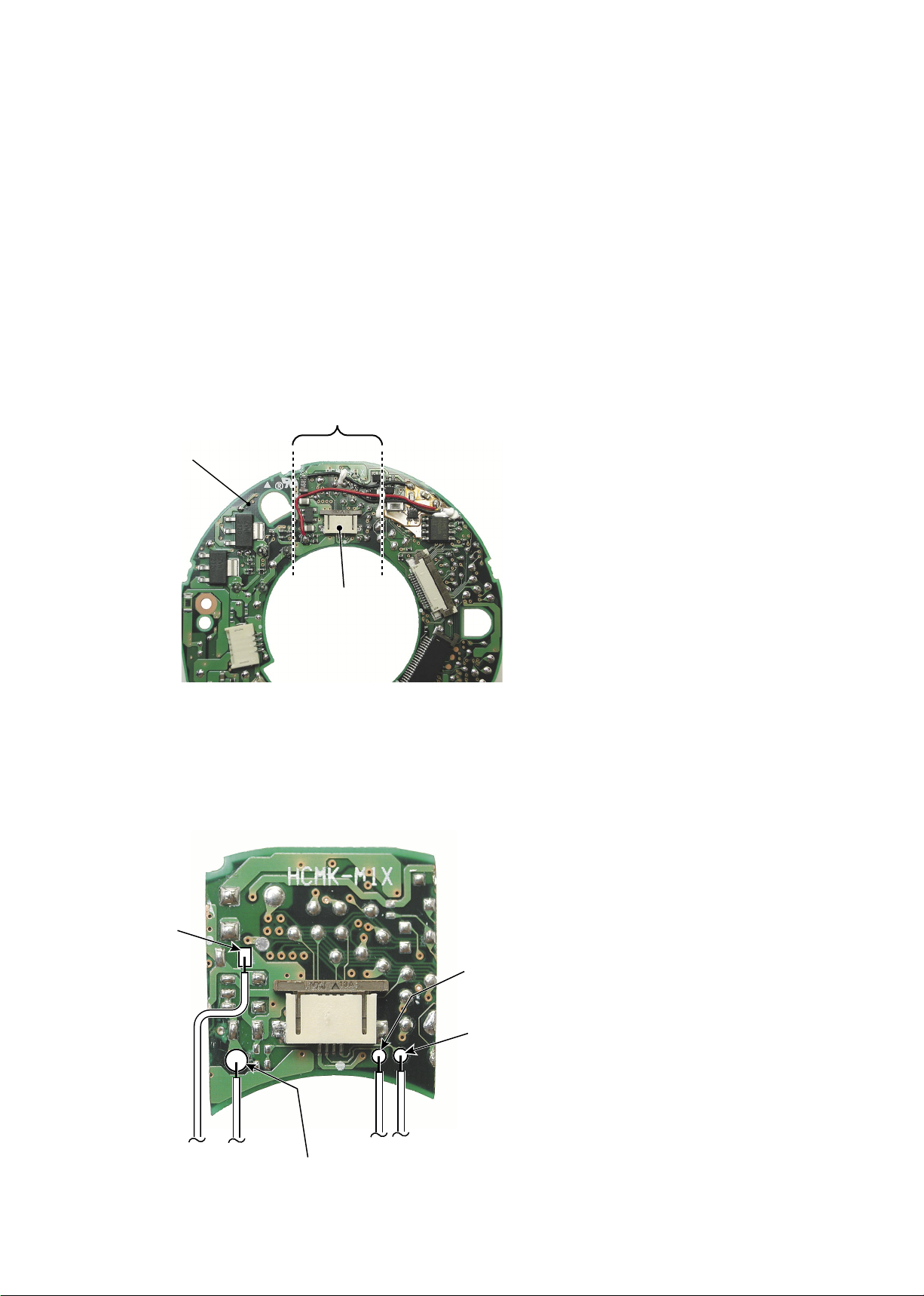
Making of self-made tool
Connector
Use this range.
Main PCB
GND
VCC(5.0V)
MR-A
MR-B
① Remove the elements (condenser, transistor,
IC, etc.) installed within the dotted line as
shown in the left from both sides of PCB.
Don’t remove the connector.
② Cut the PCB at the dotted line.
③ Solder the cords at 4 pattern places on the
PCB as shown in the left.
● It is necessary to make a self-made tool by using the RP main PCB of AF-S 24-85/3.5-4.5G. The self-made tool
will be used for "INSPECTION AND ADJUSTMENT FOR THE WAVEFORM OUTPUT FROM MR
ENCODER".
The making procedure is shown below. Make a self-made tool according to this procedure.
 Loading...