

Nieco 9015 Installation Manual

AUTOMATIC
FOOD SERVICE
EQUIPMENT
AUTOMATIC GAS BROILER
MODEL 9015
OWNERS MANUAL
IMPORTANT: RETAIN THIS MANUAL IN A SAFE PLACE
FOR FUTURE REFERENCE.
Broiler area must be kept free of combustible materials, and the flow of combustion and ventilation air
must not be obstructed. Operating personnel must not perform any maintenance or repair functions.
Contact your Nieco Authorized Dealer.
In a prominent location, post instructions to be followed in the event the user smells gas.This information shall be obtained by consulting your local gas supplier.
FOR Y OUR SAFETY:
Do not store or use gasoline or other flammable vapors or liquids in
the vicinity of this or any other appliance.
WARNING: Improper installation, adjustment, alteration, maintenance
can cause property damage, injury, or death. Read the installation,
operating and maintenance instructions thoroughly before installing
or servicing this equipment.

2
TABLE OF CONTENTS
A. General Information . . . . . . . . . . . . . . . . . . . . . . . . . . . . . . . . . . . . . . . . .3
A.1 Description . . . . . . . . . . . . . . . . . . . . . . . . . . . . . . . . . . . . . . . . . . .3
A.2 Warranty Information . . . . . . . . . . . . . . . . . . . . . . . . . . . . . . . . . . .3
A.3 Service/Technical Assistance . . . . . . . . . . . . . . . . . . . . . . . . . . . . .4
A.4 Safety Information . . . . . . . . . . . . . . . . . . . . . . . . . . . . . . . . . . . . .4
B. Machine Installation . . . . . . . . . . . . . . . . . . . . . . . . . . . . . . . . . . . . . . . . .6
B.1 Pre-Installation . . . . . . . . . . . . . . . . . . . . . . . . . . . . . . . . . . . . . . . .6
B.2 Mounting . . . . . . . . . . . . . . . . . . . . . . . . . . . . . . . . . . . . . . . . . . . .6
B.3 Leveling . . . . . . . . . . . . . . . . . . . . . . . . . . . . . . . . . . . . . . . . . . . . .6
B.4 Hood Requirements . . . . . . . . . . . . . . . . . . . . . . . . . . . . . . . . . . . .7
B.5 Clearance . . . . . . . . . . . . . . . . . . . . . . . . . . . . . . . . . . . . . . . . . . .7
B.6 Gas Connection . . . . . . . . . . . . . . . . . . . . . . . . . . . . . . . . . . . . . . .8
B.7 Flexible Gas Line Installation . . . . . . . . . . . . . . . . . . . . . . . . . . . . .8
B.8 Restraining Device . . . . . . . . . . . . . . . . . . . . . . . . . . . . . . . . . . . . .9
B.9 Electrical Connection . . . . . . . . . . . . . . . . . . . . . . . . . . . . . . . . . . .9
B.10Pre-Operation Check . . . . . . . . . . . . . . . . . . . . . . . . . . . . . . . . . . .9
C. Operation . . . . . . . . . . . . . . . . . . . . . . . . . . . . . . . . . . . . . . . . . . . . . . . . .10
C.1 Controls and Indicators . . . . . . . . . . . . . . . . . . . . . . . . . . . . . . . . .10
C.2 Step-by-Step Lighting Procedure . . . . . . . . . . . . . . . . . . . . . . . . .12
C.3 Shutdown Procedure . . . . . . . . . . . . . . . . . . . . . . . . . . . . . . . . . .14
C.4 Control Operation . . . . . . . . . . . . . . . . . . . . . . . . . . . . . . . . . . . . .15
D. Assembly/Disassembly and Cleaning . . . . . . . . . . . . . . . . . . . . . . . . . .20
E. Troubleshooting Guide . . . . . . . . . . . . . . . . . . . . . . . . . . . . . . . . . . . . . .41
F. Broil Chain Tension & Link Removal . . . . . . . . . . . . . . . . . . . . . . . . . . .43
G. Parts and Locations . . . . . . . . . . . . . . . . . . . . . . . . . . . . . . . . . . . . . . . .44
G.1 Main Chamber Removable Parts . . . . . . . . . . . . . . . . . . . . . . . . .44
G.2 Flex Chamber Removable Parts . . . . . . . . . . . . . . . . . . . . . . . . . .45
G.3 Feed End Components . . . . . . . . . . . . . . . . . . . . . . . . . . . . . . . . .46
G.4 Main Chamber Side Components . . . . . . . . . . . . . . . . . . . . . . . . .47
G.5 Flex Chamber Side Components . . . . . . . . . . . . . . . . . . . . . . . . .48
H. Wiring Diagram . . . . . . . . . . . . . . . . . . . . . . . . . . . . . . . . . . . . . . . . . . . .49
I. Specifications . . . . . . . . . . . . . . . . . . . . . . . . . . . . . . . . . . . . . . . . . . . . .50
J. Warranty Information . . . . . . . . . . . . . . . . . . . . . . . . . . . . . . . . . . . . . . .52
Nieco Corporation - Model 9015

3
A. GENERAL INFORMATION
A.1 Description
The Nieco®Model 9015 automatic broiler, utilizes dual broil chambers, high
release convection burners, electric elements, a new, simplified ignition system,
easy cleaning and a state-of-the-art computer control to help eliminate broiling
problems and provide the operator with even greater control over the broiling
environment.The 9015 is flow-through, with a heated holding area at the
discharge end.
This manual provides the safety, installation and operating procedures for the
Nieco Automatic Broiler Model 9015.We recommend that all information
contained in this manual be read prior to installing and operating the broiler.
A.2 Warranty Information
Please read the full text of the limited Warranty in this manual.
If the unit arrives damaged, contact the carrier immediately and file a damage claim with them. Save all
packing materials when filing a claim. Freight damage claims are the responsibility of the purchaser and
ARE NOT covered under warranty.
The warranty
does not extend to:
• Damages caused in shipment or damage as a result of improper use.
• Installation of electrical service.
• Normal maintenance as outlined in this manual.
• Malfunction resulting from improper maintenance not in accordance with the steps contained in
this manual and any applicable training.
• Damage caused by abuse or careless handling outside of the normal operating procedures
contained in this manual.
• Damage from moisture into electrical components.
• Damage from tampering with or removal of any safety device.
IMPORTANT!
Keep these instructions for future reference. If the unit changes ownership,
be sure this manual accompanies the equipment.
IMPORTANT
The Nieco Corporation reserves the right to change specifications and product design in
accordance with the general terms and conditions outlined in the BURGER KING®/Vendor
agreement. Such revisions do not entitle the buyer to corresponding changes, improvements,
additions or replacements for previously purchased equipment.
Nieco Corporation - Model 9015

4
A.3 Service/Technical Assistance
If you experience any problems with the installation or operation of your broiler, contact your local
Authorized Nieco Distributor.
Fill in the information bellow and have it handy when calling your authorized service agency for assistance.
The serial number is on the broiler rating plate on the side of the unit.
Purchased from:
Date of Purchase:
Model No.:
Serial No.:
For the name of your local Authorized Nieco Distributor, please call (800) 821-2141.
Use only genuine Nieco replacement parts in your broiler.Use of replacement parts other than those sup-
plied by Authorized Nieco Distributors and Service Agencies will void the warranty and may significantly
alter the performance of your broiler. Nieco and the Burger King Corporation have worked together to create a set of standards for broiler performance, food quality and food safety. The use of non-Nieco parts is
capable of affecting these criteria, and may affect broiler performance, parts longevity and food safety.Your
local Authorized Nieco Distributor and Service Agent has been factory trained and has a complete supply
of parts for your Nieco Automatic Broiler.
You may contact the factory direct at (707) 284-7100 if you have trouble locating your local Nieco
Distributor.
A.4 Important Safety Information
Throughout this manual, you will find the following safety words and symbols that signify important safety
issues with regards to operating or maintaining the equipment:
WARNING
GENERAL WARNING. Indicates
information important to the proper
operation of the equipment. Failure
to observe may result in damage to
the equipment and/or severe bodily
injury or death.
WARNING
ELECTRICAL WARNING. Indicates
information relating to possible
shock hazard. Failure to observe
may result in damage to the equipment and/or severe bodily injury or
death.
CA UTION
GENERAL CAUTION. Indicates
information important to the proper
operation of the equipment. Failure
to observe may result in damage to
the equipment.
WARNING
HOT SURFACE WARNING. Indicates
information important to the handling of equipment and parts.
Failure to observe caution could
result in personal injury.
Nieco Corporation - Model 9015

5
A.4 Important Safety Information (Continued.)
In addition to the warnings and cautions in this manual, use the following guidelines for safe operation of
your Nieco Automatic Broiler:
• Read and follow all instructions before using this equipment.
• Install or locate broiler only for its intended use as described in this manual.
• Do not operate this equipment if it has a damaged cord or plug, if it is not working properly or if it
has been otherwise damaged.
• This equipment should only be serviced by authorized personnel. Contact your local Nieco
Distributor for adjustment or repair.
• Use only genuine Nieco replacement parts for your broiler. Failure to do so will void the warranty
and may significantly alter the performance of your broiler. Nieco and the Burger King
Corporation have worked together to create a set of standards for broiler performance, food quality
and food safety. The use of non-Nieco parts is capable of affecting these criteria, and may affect
broiler performance, parts longevity and food safety.
The following warnings and cautions appear throughout the manual and should be carefully
observed:
• Turn the broiler off, close the main gas valve, and disconnect the plug before
performing any service, maintenance or cleaning on the broiler.
• Always allow the broiler to fully cool before performing any service, maintenance or
cleaning. Failure to wait for the broiler to cool fully may result in personal injury.
• The procedures in this manual may include reference to the use of chemical products.The
Nieco Corporation does not endorse the use of any particular cleaning/degreasing agent.
Use only those chemicals that are approved for use in the BURGER KING® SYSTEM.
• The broiler should be grounded according to local electrical codes to prevent the
possibility of electrical shock. It requires a grounded receptacle with separate electrical
lines, protected by fuses or circuit breakers of the proper rating.
• All electrical connections must be in accordance with local electrical codes and any other
applicable codes.
• The use of adequate ventilation (as rated in this manual) with this broiler is mandatory.
Failure to adequately ventilate this unit and provide safe operating distances (as specified
in this manual) is a fire safety hazard. Follow the instructions for emergency broiler
shutdown in the event of an emergency.
• No attempt should be made to operate this appliance in the event of a power failure.
WARNING ELECTRICAL SHOCK HAZARD. FAILURE TO FOLLOW THESE INSTRUCTIONS COULD
RESULT IN SERIOUS INJURY OR DEATH:
_
Electrical ground is required on this appliance.
_
Check with a qualified electrician if you are in doubt as to whether the appliance is properly
grounded.
_
Do not use water on or near the control box located on the underside of the broiler for risk
of serious injury or death due to electrical shock.
WARNING,HIGH TEMPERATURES WITH HOT SURFACES. FAILURE TO FOLLOW THESE PROCEDURES COULD RESULT IN SERIOUS INJURY:
_
Do not attempt to clean, disassemble or perform maintenance on this broiler until it is fully
cooled as per the instructions contained in this manual.
Nieco Corporation - Model 9015

6
Nieco Corporation - Model 9015
B. INSTALLATION
B.1 Pre-Installation
Uncrate the broiler and inspect for shipping damage. Remove the tape securing the machine par ts, and
install the parts in their proper location. Refer to the Parts and Location section of this manual. If there
are obvious or concealed damages to any part of the broiler, please contact your freight carrier.The factory warranty does not cover freight damage.
B.2 Mounting
Follow the mounting instructions if this function is not performed by the installer.
B.3 Leveling
The grease drain system is based on a gravity-flow design. Therefore, it is extremely important to level
the broiler during installation. Use levelling shims (P/N 11936).
ITEM P/N QTY DESCRIPTION
1 12631 2 Stand Leg Assembly
2 12632 1 Shear Plate
3 95099 4 Caster
4 10476 4 3/8”-16 X 7/8” Bolt
5 10477 4 3/8”-16 Lock Nut
6 10475 8 3/8”-16 X 2 3/4” Bolt
CA UTION
Prior to mating stand to broiler, and
with stand in operating location, verify
that stand is level within 1/8”. If not,
shim as required.
SHIM INSTALLATION:
1. Prior to mating stand to broiler and with stand in operating position, verify
that stand is level within an 1/8”inch.
2. If shimming is required, determine which caster(s) should be shimmed.
3. Elevate side of stand to be shimmed off of floor.
4. Remove caster(s) to be shimmed.
5. When installing shims, remove existing hardware, discard washers (ITEM 2),
and reuse nuts and bolts.
6. After adding shim(s) and securing caster(s), lower broiler.
7. Check to verify that broiler is now level.
ITEM P/N QTY DESCRIPTION
1 11936 AR Stand Shim
2 5599 REF 3/8” Washer
3 11888 REF 3/8X1 1/4” Bolt
4 10477 REF 3/8” Locknut
7
Nieco Corporation - Model 9015
B.4 Hood Requirements
This appliance must be installed under a ventilation hood of adequate size and the following minimum
capacity:
Model SCFM
9015 1050
Do not obstruct the flow of combustion and ventilation air. An adequate air supply must be available for
safe and proper operation.
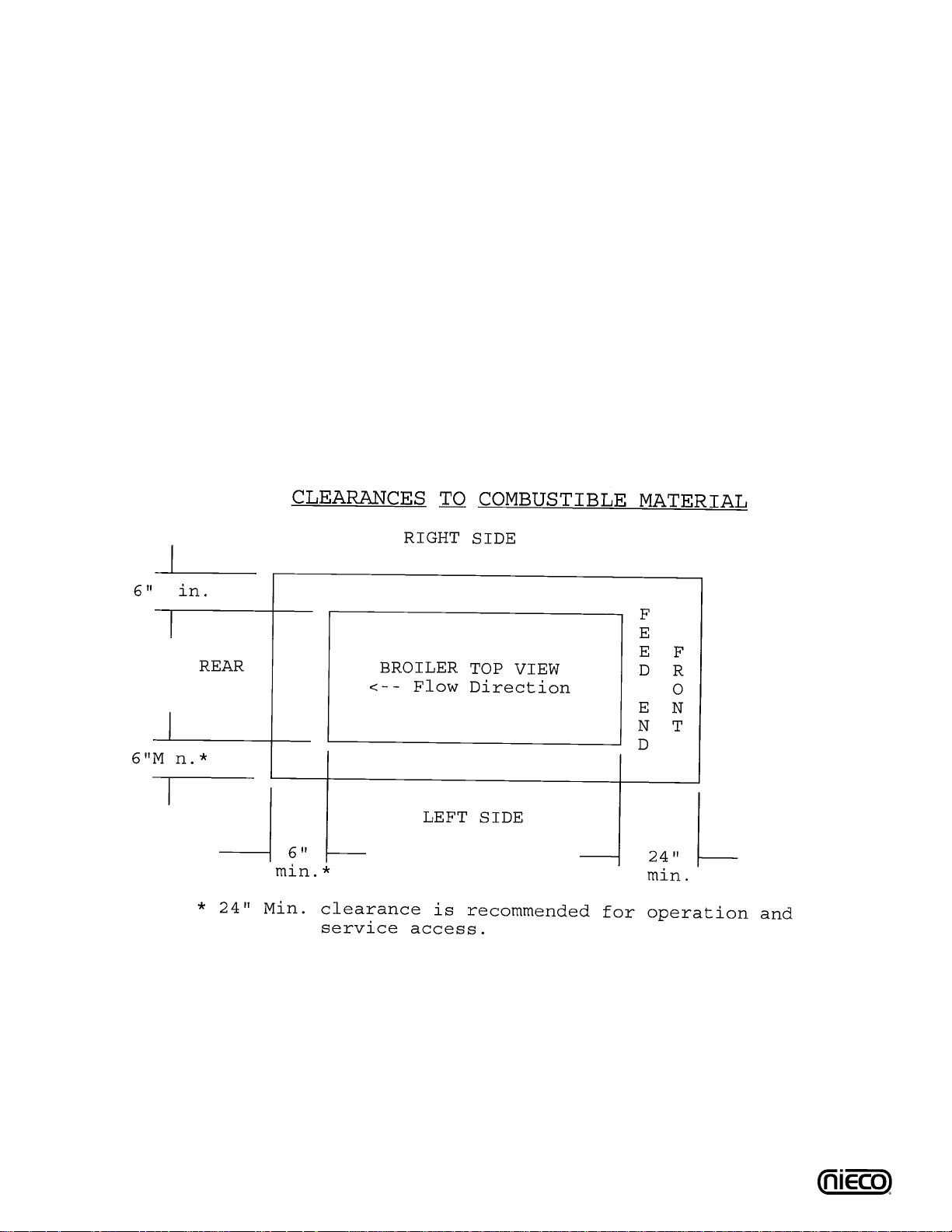
B.5 Clearance
For proper installation the minimum clearance from combustible and non-combustible construction must
be 6” (305 mm) from the back and 24” (610 mm) from the front of the machine. Keep appliance area
free from combustibles.
To facilitate disassembly and service of the unit a minimum of 24” (610 mm) should be allowed on the
control panel (feed end) of the broiler, as well as in front and back of the broiler.

8
B.6 Gas Connection- 3/4” N.P.T.
At rated input the gas supply should deliver a minimum pressure of at least 15 mbar (6" water column) at the broiler
connection for natural gas.Incoming gas supply pressure must not exceed 50 mbar (14" water column).
Note: The installation of this appliance must conform with local codes, or in the absence of local codes, with the
National Fuel Gas Code, ANSI Z223.1, Natural Gas Installation Code, CAN/CGA-B149.1 including:
1. The appliance and its individual shutoff valve must be disconnected from the gas supply
piping system during any pressure testing of that system at test pressures in excess of
1/2 psi (3.45 kPa).
2. The appliance must be isolated from the gas supply piping system by closing its
individual manual shutoff valve during any pressure testing of the gas supply piping
system at test pressures equal to or less than 1/2 psi (3.45 kPa).
By public initiative, the State of California has adopted legislation (Proposition 65) which requires manufacturers of many types of products, including gas appliances, to warn consumers of their products that contain chemicals or produce substances listed by the State of California to either cause cancer, birth defects
or other reproductive harm.
Nieco Corporation - Model 9015
For safety in the kitchen area, and to insure maximum
service life, it is vitally important to correctly install connectors. The connector shall comply with the Standard for
Connectors for Moveable Gas Appliances, ANSI Z21.69 or
CAN/CGA-6.16 and a quick disconnect device that complies with the Standard for Quick-Disconnect Devices for
use with gas fuel, ANSI Z21.41 or CAN1-6.9
In order to avoid sharp kinks or excessiv e bends that could
have a damaging effect on the connector, it may be necessary to attach pipe elbows in order to bring the connector
into its proper plane. For easy movement of the appliance,
the connector should be installed with a "lazy" loop for minimum tension.
Note: Gas appliances should be disconnected prior to
maximum movement. (Minimal movement is possible
to connect hose.)
B.7 Installing Gas Appliance Connectors and Flexible Gas Lines Correctly
WARNING
If not installed, operated and maintained in accordance with the manufacturers instructions, this
product could expose you to substances in fuel or from fuel combustion which can cause cancer,
birth defects or other reproductive harm.
9015 Equipment Side Gas
Connection
9015 Manual
Gas Valve
Correct Gas Line
Installation

9
Nieco Corporation - Model 9015
B.9 Electrical Connection
Power requirements are stated on the unit nameplate and must be connected accordingly.This appliance, when installed must be electrically grounded in accordance with local codes, or in the absence of
local codes, with the National Electrical Code, ANSI/NFPA 70, or the Canadian Electr ical Code, CSA
C22.2, as applicable.Before star ting broiler, tighten all electrical connections in control box. An electrical
wiring diagram can be found inside the control box.
Note: Disconnect power before servicing.
B.10 Pre-Operation Check
Be sure that all parts are installed in the proper location:
❏ Ventilation is turned on
❏ Broiler is plugged in
❏ Gas line is connected
B.8 Restraining Device Installation and Use
This high strength restrainer is to be used with all moveable (castered) appliances. It fully complies with
American Gas Association requirements. References: Z21.69, Z83.11, and Z21.41 with current revisions.
Installation is quick and positive.In Canada, device is in accordance with CAN 1-6.9-M70 Quick
Disconnect Devices for use with gas fuel, and CAN 1-6.10-88 metal connectors for gas appliances.
Correct length for any appliance is simply a matter of loosening two adjuster clips (1) and re-tightening.
(3" to 6" shorter than appliance connector is desired length.) Restrainer is made of heavy duty steel
cable, with a strong scissor hood (2) at one end, and an equally strong spring hook (3) at the other.
Cotter pin (4) is supplied to secure the installation. For proper attachment to the broiler, use the supplied
hardware to attach the device to the holes in the shear plate of the broiler stand.
NOTE: If disconnection of the restraint is necessary, reconnect the restraint after the appliance
has been returned to its originally installed position.
10
C. OPERATION
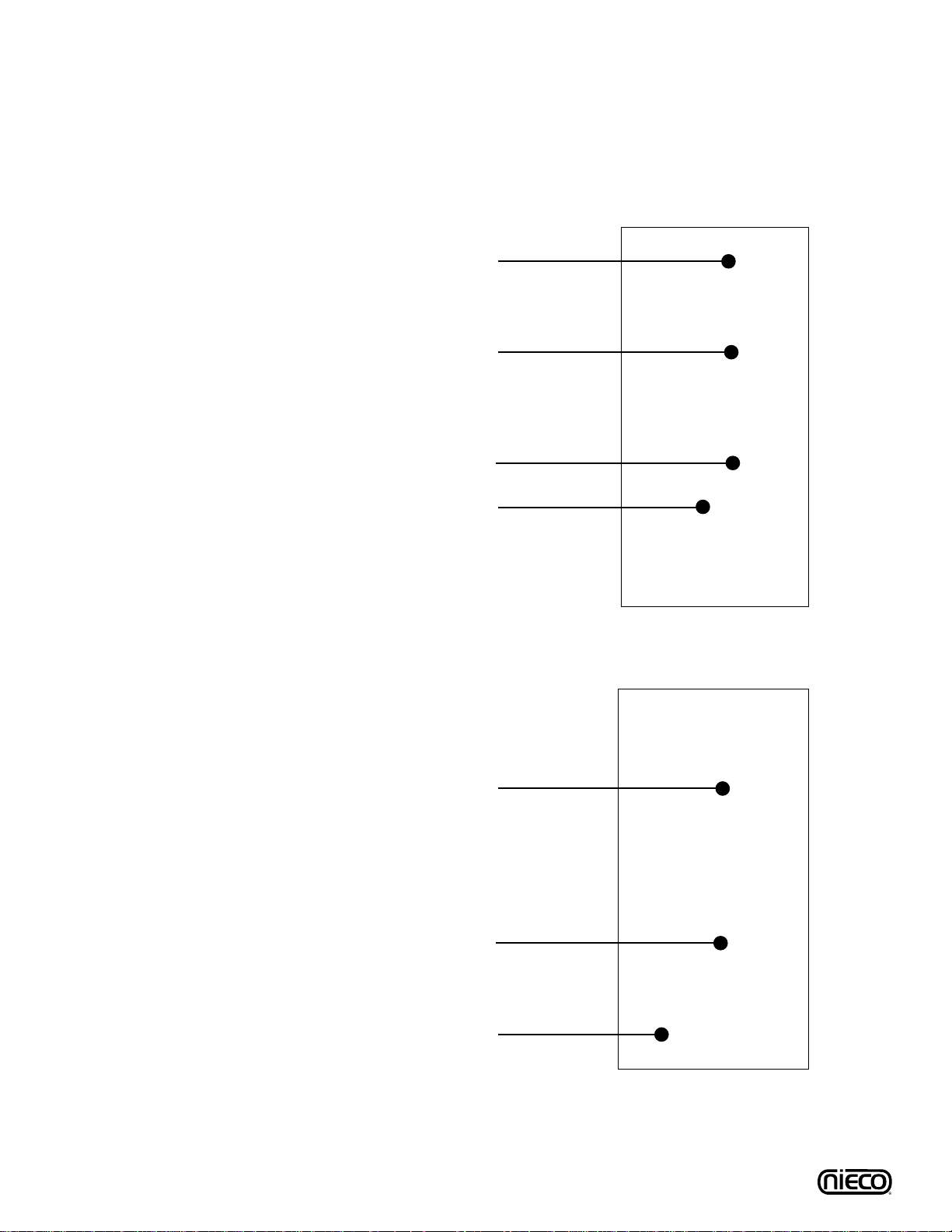
C.1 Controls and Indicators
ON THE FLEX CHAMBER SIDE
Red Pilot Button (P/N 12143)
Gas Pressure Gauge (P/N 2001)
Ignitor Reset Button (P/N 11025)
Main On/Off Switch (P/N 12364)
ON THE MAIN CHAMBER SIDE
Upper Red Pilot Button (P/N 12143)
Lower Red Pilot Button (P/N 12143)
Gas Pressure Gauge (P/N 2001)
Nieco Corporation - Model 9015

11
C.1 Controls and Indicators (Continued.)
(1) IR READY - Infra-red port for remote control programming (not currently used).
(2) LED DISPLAY
(3) LEFT MENU SELECTION BUTTON
(4) RIGHT MENU SELECTION ARROW
(5) UP PRODUCT SELECTION BUTTON - Press to change active product selected.
(6) DOWN PRODUCT SELECTION BUTTON- Press to change active product selected.
(7) SELECT BUTTON - Press to enter selection.
(8) HEAT BUTTON - Press to change top heat settings for Flex chamber (belt 2) ONLY.
(9) TIME BUTTON - Press to change cook time of active chain.
(1)
(2)
(4)
(9) (8)
(5)
(6)
(7)
(3)
Nieco Corporation - Model 9015
12
C.2 Lighting Procedures
1. Broiler is
centered under
hood and
plugged in
2. Gas valve is
open when
handle is in line
(parallel to) the
pipe
3. Turn ventilation
system on
PILOTS MUST BE LIT WITHIN 5 MINUTES; IF YOU EXCEED 5
MINUTES, PRESS THE RESET BUTTON NEXT TO THE ON/OFF
SWITCH AND REPEAT IGNITION PROCEDURES. IF REIGNITION FAILS, COMPLETELY SHUT OFF THE BROILER,WAIT 5
MINUTES AND REPEAT THE IGNITION PROCEDURES.
Reset Button
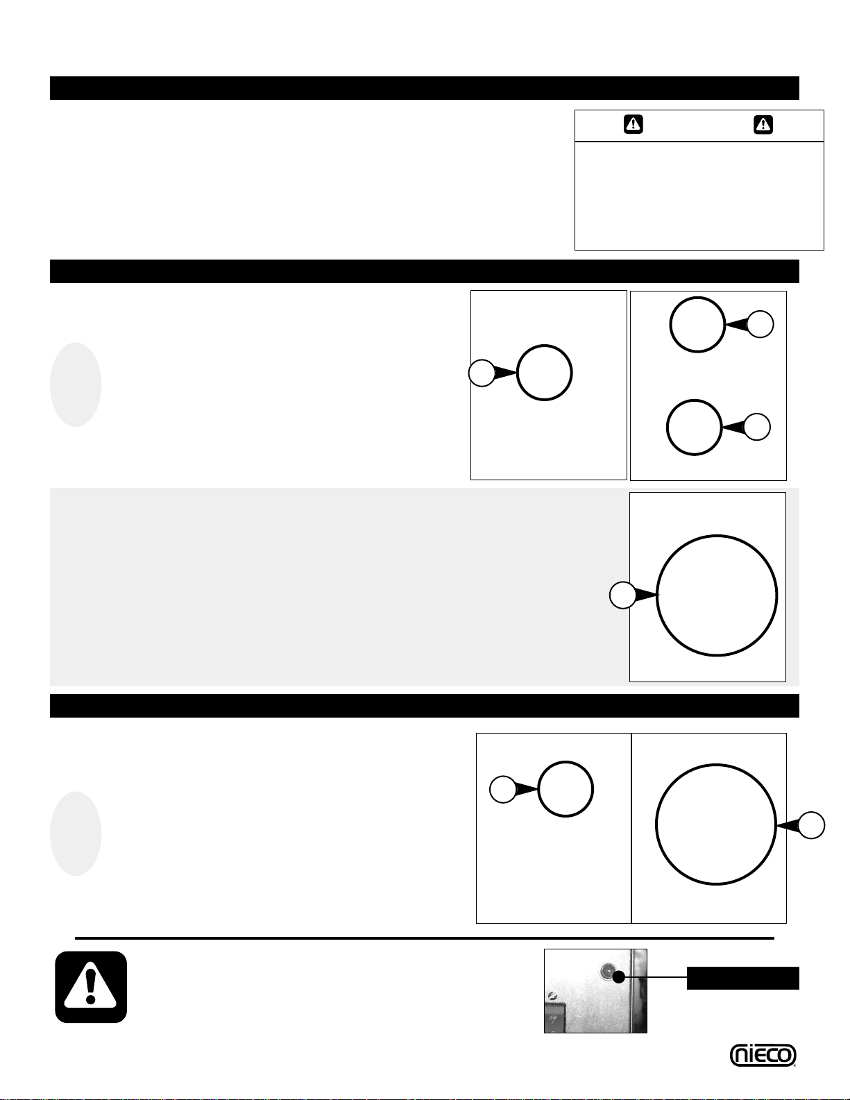
1
Turn the MAIN POWER SWITCH (a) on. Starting
with the MAIN CHAMBER RED PILOT BUTTONS,
press and hold the
LOWER BUTTON FIRST (b) for
30 seconds after the pilot has lit. Then press the
UPPER PILOT BUTTON (c) for 30 seconds after
the pilot has lit.
2
After releasing red pilot buttons; check GAS PRES-
SURE GAUGE (a) reading. Gauge should read 4.5”.
If not, follow troubleshooting tips in section E of this
manual.Verify that main chamber burners - upper
and lower - have lit.
3
Move to the FLEX CHAMBER RED PILOT
BUTTON (a), push and hold for 30 seconds after
the pilot has lit. Release, and verify that the burners
have lit, and that the
GAS PRESSURE GAUGE (b)
reads 4”.
a
WARNING
THE VENTILATION SYSTEM MUST
BE ON AT ALL TIMES DURING
BROILER OPERATION. OPERATING
BROILER WITHOUT PROPER
VENTILATION IS A SEVERE FIRE
HAZARD.
MAIN CHAMBER IGNITION
b
c
PRE-LIGHTING PREPARATION
FLEX CHAMBER IGNITION
a
a
b
Nieco Corporation - Model 9015
13
C.2 Lighting Procedures (Continued.)
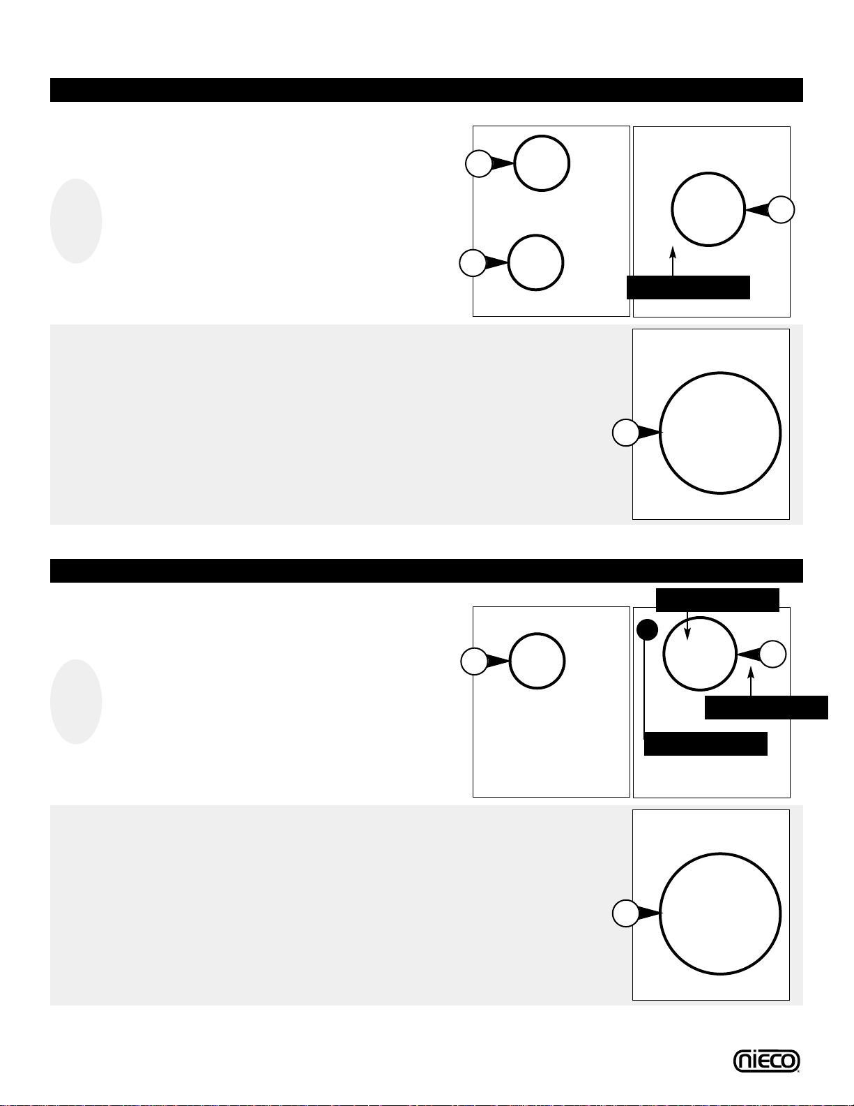
MANUAL IGNITION - MAIN CHAMBER
MANUAL IGNITION - FLEX CHAMBER
1
Remove the GREASE PAN (not pictured - see DIS-
ASSEMBLY). Press and hold the
PILOT BUTTON
(a) and place the long stemmed lighter or match on
the PILOT BURNER (b) located on the outboard
(manifold) side of the flex chamber. After pilot is lit,
hold pilot button for 30 seconds and release.
2
After releasing pilot button, verify that LOWER
BURNERS have lit and that the GAS PRESSURE
GAUGE
reads 4” (a).
a
b
a
LOWER BURNER
Nieco Corporation - Model 9015
LIGHTER/MATCH
PILOT
1
Press and hold the LOWER PILOT BUTTON (a).
Use match or long-stemmed lighter to light
PILOT
TUBES (b)
. Light the pilot closest to the feed end of
the broiler.After pilot has lit, hold pilot button for 30
seconds and release. Repeat for the
UPPER PILOT
BUTTON (c).
2
After releasing red pilot buttons; check GAS
PRESSURE GAUGE (a) reading. Gauge should read
4.5”. If not, follow troubleshooting tips in section E of
this manual.Verify that main chamber burners upper and lower - have lit.
a
b
a
c
LIGHTER/MATCH

14
1. Allow the broiler
to run free of
any product for
10 minutes.
This will burn
the chain clean.
2. Turn off the
Main Power
Switch (a).
3. Wait for 30
minutes for the
broiler to cool.
C.3 Shutdown Procedures
2. Close the MAIN
GAS V ALVE (b)
Valve is closed
when it is perpendicular to pipe
a
PLANNED SHUTDOWN
WARNING
Always leave the ventilation hood
on while the broiler is cooling.
Failure to do so is both a fire risk
and could result in damage to the
broiler.
EMERGENCY SHUTDOWN
1. Turn off the
MAIN POWER
SWITCH (a)
a
b
Your Nieco Automatic Broiler is designed to automatically stop gas flow to the broiler in the event of
power failure, gas pressure loss or any other related incident. No attempt to operate this appliance
should be made in the event of a power failure.
CA UTION
In a prominent location, post
instructions to be followed in the
event the user smells gas.This
information shall be obtained by
consulting your local gas supplier.
CA UTION
FOR YOUR SAFETY: Do not store
or use gasoline or other flammable
vapors or liquids in the vicinity of
this or any other appliance.
Nieco Corporation - Model 9015
CA UTION
FOR YOUR SAFETY: In the event of
a prolonged power failure, no
attempt should be made to operate
this appliance.
CA UTION
Allow the broiler to fully cool
BEFORE beginning disassembly
and cleaning. Failure to do so
could result in serious injury.

15
C.4 Control Operation
IMPORTANT: THIS BROILER IS SHIPPED WITH FACTORY PRESETS THAT MUST BE CHANGED.
If this is the initial start-up for your broiler, ALLcontrol settings must be made according to BURGER KING® specifications. Follow the
steps outlined for calibration, changing preset times and setting the fle x chamber element heat settings to properly set up this broiler.
Nieco Corporation - Model 9015
Turn Main Power Switch on. Light the broiler following the
lighting procedures. If you have not calibrated your broiler in
40 power-ons, approximately one month (SEE Pg. 19 POWER
ON SCREEN), the broiler will display PLEASE PRESS RESET
ATC.Press the Reset ATC button to begin a 45 minute calibration of the broiler.NOTE: This screen will only appear if your
broiler requires calibration. Otherwise, your broiler will go into
Fast Warm (SEE BELOW).
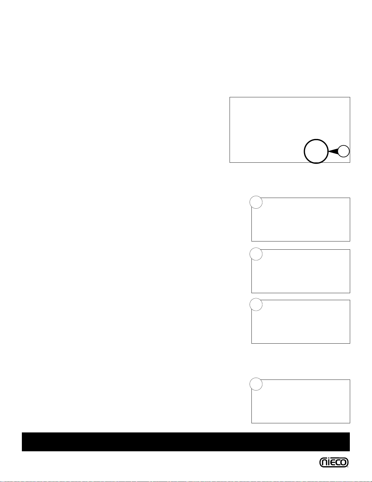
C.4.1 WARMING UP
The broiler will be in ‘Fast Warm’mode. This will quickly heat
the broiler to the Automatic Temperature Control set point.
Allow the broiler 45 minutes to get to proper cooking temperature. During the warm-up period the broil chains will move at
their slowest speed.
DO NOT COOK DURING WARM-UP!
If necessary, the broiler can automatically calibrate itself to a
new Automatic Temperature Control (ATC) set point. Press the
right hand Menu Selection button, which is pointing to “Reset
ATC” on the display.The broiler will be in calibration mode for
45 minutes.To stop the calibration process, press the arrow
below “cancel”.The set point will default to 600°F (315°C).The
set points will have to be manually set (SEE ADJUSTING ATC
SET POINT). During this time the conveyor will move at the
slowest possible speed.
DO NOT COOK DURING CALIBRATION!
C.4.2 CALIBRATION
After warm-up or calibration, the broiler will switch to Normal
Operation or Cooking mode. NOTE: The broiler now lets each
chamber come out of pre-heat after each chamber reaches
the set point. SHOWN: Flex chamber (B2) is not ready for
cooking. Once B2 has reached temperature, screen will show
product name and cook time.
DO NOT COOK ON A CHAMBER UNTIL IT COMES OUT
OF PRE-HEAT.
C.4.3 PRE-HEAT MODE
Cooking >>>>>>>>
B1 Whopper 02:00
B2 Pre Heating XXX
Menu

16
Nieco Corporation - Model 9015
After warming up or calibrating, the broiler will switch into
“Cooking” mode. The conveyors will adjust to their set speeds
and the broiler is ready for normal use. B1 is the large “Main”
or left chain; B2 is the small “Flex” or right chain.
C.4.4 NORMAL OPERATION
Cooking >>>>>>>>
B1 Whopper 02:00
B2 Chicken 04:30
Menu
The FLEX belt has eight preset products. Each of these can
be programmed for different cook times and heater settings.To
change the current product, first choose which belt to change.
Press the UP or DOWN ARROWS to switch between Belt 1
(Main) and Belt 2 (Flex).When the proper belt has been
selected, press the SELECT button, then use the UP ARROW
to scroll through the active product menu items.Using the
DOWN ARROW will scroll through all of the recipes.Press
SELECT to make the change.The broiler will return to
Cooking mode.
C.4.5 SELECTING PRODUCTS
Select >>>>>>>>
B1 Whopper 02:00
B2 Chicken 04:30
Menu
Press “Time” to change the belt speed for the active product.The control will go into “Edit” mode. Use the UP or DOWN ARROWS to change
the cook time. Increasing the cook time will increase the product temperature. Press “Save” or “SELECT” to lock in the change and return to
cook mode. Press “Exit” if no change is desired.
C.4.6 CHANGING COOK TIMES
To change the names of products in the memory, press the TIME and
HEAT buttons simultaneously. This will get you into edit mode. Starting
with the first letter, use the up or down arrows to scroll through the
alphabet to choose upper or lower case letters, symbols or numbers.
Press SELECT to move to the next space.When finished, press SAVE
to store the new names in memory. Press EXIT to return to cooking
mode without saving changes.
C.4.7 PROGRAMMING PRODUCT NAMES
Edit Belt 2 >>>>>
04:30 Hf 75%
Chicken Hb 85%
Save Exit
Cook
Time
IMPORTANT: Cook times and element settings shown are
starting points. Be sure to adjust the broiler so products are
cooked according to BURGER KING® specifications.
Edit Belt 2 >>>>>
04:30 Hf 70%
Chicken Hb 85%
GAS - HI
Save Exit
Cook
Time
17
Nieco Corporation - Model 9015
IF YOU HAVE ADDED OR ARE INSTALLING A CATALYST TO YOUR 9015, FOLLOW THESE
INSTRUCTIONS TO RE-CALIBRATE YOUR BROILER.
NOTE:These instructions require version 1.17 of the control operating
software for the Model 9015 (the software revision number can be found
on the first screen after turning the broiler on - picture a).
1. Turn the broiler ON and note which revision software is installed on the
broiler (see above).If your broiler does NOT have revision 1.17 of the
software, contact Nieco for information about upgrading.
2. After turning the broiler on, the PRE-HEAT FAST screen will appear.Press
the two arrows together to enter the TEMPERATURE MENU.
3. If necessary, use the UP/DOWN arrows to highlight the SETATCCATALYST
selection.The press the SELECT button to enter the ATCCATALYST MENU.
4. Use the DEFAULT soft key to toggle between the setback configurations to
adjust the setback temperature according to the B1 chamber configuration of
your broiler:
9015/9025 with perforated top 30ºF
9015 with a 24” X24” catalyst 10ºF
9015 with an 18” X 24” catalyst 15ºF
9025 with an 18” X24” catalyst 15ºF
NOTE: You may also use the UP/DOWN ARROWS to manually adjust the
setback temperature.Press the SAVE button to exit this menu.Turn the
broiler off.
5. Light the broiler, and press the RESET ATC button. This will start the broiler
into a 45-minute automatic calibration mode.
DO NOT ATTEMPT TO COOK
WHILE THE BROILER IS IN AUTOMATIC CALIBRATION MODE.
When the broiler is out of automatic calibration, the display will be in the
COOKING MENU (Normal operation).
a
2
3
4
5
IMPORTANT: After calibration is complete, be sure to adjust the broiler so products are
cooked according to BURGER KING® specifications.
C.4.8 CATALYST AUTO-CALIBRATION
C.4 Control Operation
 Loading...